JP2014535056A - Systems and methods for simultaneous multidirectional imaging for capturing tomographic data - Google Patents
Systems and methods for simultaneous multidirectional imaging for capturing tomographic data Download PDFInfo
- Publication number
- JP2014535056A JP2014535056A JP2014540233A JP2014540233A JP2014535056A JP 2014535056 A JP2014535056 A JP 2014535056A JP 2014540233 A JP2014540233 A JP 2014540233A JP 2014540233 A JP2014540233 A JP 2014540233A JP 2014535056 A JP2014535056 A JP 2014535056A
- Authority
- JP
- Japan
- Prior art keywords
- subject
- optical element
- light
- imaging device
- imaging system
- Prior art date
- Legal status (The legal status is an assumption and is not a legal conclusion. Google has not performed a legal analysis and makes no representation as to the accuracy of the status listed.)
- Pending
Links
- 238000003384 imaging method Methods 0.000 title claims abstract description 101
- 238000000034 method Methods 0.000 title claims abstract description 22
- 230000003287 optical effect Effects 0.000 claims abstract description 81
- 238000003325 tomography Methods 0.000 claims abstract description 17
- 238000005286 illumination Methods 0.000 claims description 26
- 230000033001 locomotion Effects 0.000 claims description 12
- 230000008859 change Effects 0.000 claims description 6
- 238000009543 diffuse optical tomography Methods 0.000 claims description 5
- 238000012634 optical imaging Methods 0.000 claims description 5
- 238000006073 displacement reaction Methods 0.000 claims description 4
- 230000029918 bioluminescence Effects 0.000 claims description 3
- 238000005415 bioluminescence Methods 0.000 claims description 3
- 230000001678 irradiating effect Effects 0.000 claims description 2
- 238000012545 processing Methods 0.000 claims description 2
- 238000013519 translation Methods 0.000 claims description 2
- 241001465754 Metazoa Species 0.000 description 9
- 210000000481 breast Anatomy 0.000 description 4
- 210000000038 chest Anatomy 0.000 description 4
- 238000005259 measurement Methods 0.000 description 4
- 230000000694 effects Effects 0.000 description 3
- 230000005540 biological transmission Effects 0.000 description 2
- 238000010276 construction Methods 0.000 description 2
- 210000002683 foot Anatomy 0.000 description 2
- 238000001727 in vivo Methods 0.000 description 2
- 238000012986 modification Methods 0.000 description 2
- 230000004048 modification Effects 0.000 description 2
- 230000005855 radiation Effects 0.000 description 2
- SNQQDAKCVSFSOV-UHFFFAOYSA-N O=NC[IH]CCC1CC=CC1 Chemical compound O=NC[IH]CCC1CC=CC1 SNQQDAKCVSFSOV-UHFFFAOYSA-N 0.000 description 1
- 238000010521 absorption reaction Methods 0.000 description 1
- 210000003484 anatomy Anatomy 0.000 description 1
- 238000010171 animal model Methods 0.000 description 1
- 210000003423 ankle Anatomy 0.000 description 1
- QVGXLLKOCUKJST-UHFFFAOYSA-N atomic oxygen Chemical compound [O] QVGXLLKOCUKJST-UHFFFAOYSA-N 0.000 description 1
- 230000002238 attenuated effect Effects 0.000 description 1
- 239000003181 biological factor Substances 0.000 description 1
- 239000000090 biomarker Substances 0.000 description 1
- 238000006243 chemical reaction Methods 0.000 description 1
- 230000006835 compression Effects 0.000 description 1
- 238000007906 compression Methods 0.000 description 1
- 238000013480 data collection Methods 0.000 description 1
- 238000003745 diagnosis Methods 0.000 description 1
- 239000000835 fiber Substances 0.000 description 1
- 230000004907 flux Effects 0.000 description 1
- 238000007689 inspection Methods 0.000 description 1
- 230000007246 mechanism Effects 0.000 description 1
- NJPPVKZQTLUDBO-UHFFFAOYSA-N novaluron Chemical compound C1=C(Cl)C(OC(F)(F)C(OC(F)(F)F)F)=CC=C1NC(=O)NC(=O)C1=C(F)C=CC=C1F NJPPVKZQTLUDBO-UHFFFAOYSA-N 0.000 description 1
- 239000013307 optical fiber Substances 0.000 description 1
- 229910052760 oxygen Inorganic materials 0.000 description 1
- 239000001301 oxygen Substances 0.000 description 1
- 230000000737 periodic effect Effects 0.000 description 1
- 238000001028 reflection method Methods 0.000 description 1
- 238000011160 research Methods 0.000 description 1
- 238000012827 research and development Methods 0.000 description 1
Images


Classifications
-
- A—HUMAN NECESSITIES
- A61—MEDICAL OR VETERINARY SCIENCE; HYGIENE
- A61B—DIAGNOSIS; SURGERY; IDENTIFICATION
- A61B5/00—Measuring for diagnostic purposes; Identification of persons
- A61B5/0059—Measuring for diagnostic purposes; Identification of persons using light, e.g. diagnosis by transillumination, diascopy, fluorescence
- A61B5/0073—Measuring for diagnostic purposes; Identification of persons using light, e.g. diagnosis by transillumination, diascopy, fluorescence by tomography, i.e. reconstruction of 3D images from 2D projections
-
- A—HUMAN NECESSITIES
- A61—MEDICAL OR VETERINARY SCIENCE; HYGIENE
- A61B—DIAGNOSIS; SURGERY; IDENTIFICATION
- A61B5/00—Measuring for diagnostic purposes; Identification of persons
- A61B5/0059—Measuring for diagnostic purposes; Identification of persons using light, e.g. diagnosis by transillumination, diascopy, fluorescence
- A61B5/0071—Measuring for diagnostic purposes; Identification of persons using light, e.g. diagnosis by transillumination, diascopy, fluorescence by measuring fluorescence emission
-
- A—HUMAN NECESSITIES
- A61—MEDICAL OR VETERINARY SCIENCE; HYGIENE
- A61B—DIAGNOSIS; SURGERY; IDENTIFICATION
- A61B5/00—Measuring for diagnostic purposes; Identification of persons
- A61B5/0059—Measuring for diagnostic purposes; Identification of persons using light, e.g. diagnosis by transillumination, diascopy, fluorescence
- A61B5/0077—Devices for viewing the surface of the body, e.g. camera, magnifying lens
-
- A—HUMAN NECESSITIES
- A61—MEDICAL OR VETERINARY SCIENCE; HYGIENE
- A61B—DIAGNOSIS; SURGERY; IDENTIFICATION
- A61B5/00—Measuring for diagnostic purposes; Identification of persons
- A61B5/0059—Measuring for diagnostic purposes; Identification of persons using light, e.g. diagnosis by transillumination, diascopy, fluorescence
- A61B5/0082—Measuring for diagnostic purposes; Identification of persons using light, e.g. diagnosis by transillumination, diascopy, fluorescence adapted for particular medical purposes
- A61B5/0091—Measuring for diagnostic purposes; Identification of persons using light, e.g. diagnosis by transillumination, diascopy, fluorescence adapted for particular medical purposes for mammography
Landscapes
- Health & Medical Sciences (AREA)
- Life Sciences & Earth Sciences (AREA)
- Biomedical Technology (AREA)
- Molecular Biology (AREA)
- Veterinary Medicine (AREA)
- Biophysics (AREA)
- Pathology (AREA)
- Engineering & Computer Science (AREA)
- Public Health (AREA)
- Heart & Thoracic Surgery (AREA)
- Medical Informatics (AREA)
- Physics & Mathematics (AREA)
- Surgery (AREA)
- Animal Behavior & Ethology (AREA)
- General Health & Medical Sciences (AREA)
- Nuclear Medicine, Radiotherapy & Molecular Imaging (AREA)
- Radiology & Medical Imaging (AREA)
- Investigating Or Analysing Materials By Optical Means (AREA)
- Investigating, Analyzing Materials By Fluorescence Or Luminescence (AREA)
Abstract
表面画像の光線を単一の撮像デバイスに導く能力を提供しつつ、被検体に戻る反射光を最小限にする光学システムによって、透過した光と後方散乱した表面光とがイメージングされるトモグラフィのイメージングに向けたデバイス、システム、および方法が説明される。一実施形態では、湾曲した反射器が部分的または完全に被検体を囲み、この反射器は、光を撮像カメラの方に反射するために傾いている。【選択図】図2Tomography imaging where transmitted light and backscattered surface light are imaged by an optical system that minimizes reflected light back to the subject while providing the ability to direct surface image rays to a single imaging device Devices, systems, and methods are described. In one embodiment, a curved reflector partially or completely surrounds the subject, and the reflector is tilted to reflect light toward the imaging camera. [Selection] Figure 2
Description
[連邦政府資金による研究開発の記載]
本発明は、国立癌研究所に認められたNCI−4R33CA118666に基づき、政府支援によってなされた。合衆国政府は、本発明における特定の権利を有する。
[Description of federal funded research and development]
This invention was made with government support based on NCI-4R33CA118666 approved by the National Cancer Institute. The United States government has certain rights in the invention.
拡散光トモグラフィ(DOT)では、被験体における発色団(または、用いられる場合には蛍光体)の3次元分布を求めるために、被験体の表面における光イメージングが用いられる。被験体には実験動物や人体の部位が含まれ得る。この3次元分布は、バイオマーカーと、酸素や特定の対象分子などの生理学的パラメータとの追跡を可能にし得る。この技術は非侵襲であり、有害な放射線を使用しない。 In diffuse optical tomography (DOT), optical imaging on the surface of a subject is used to determine a three-dimensional distribution of chromophores (or phosphors, if used) in the subject. Subjects can include experimental animals and human body parts. This three-dimensional distribution may allow tracking biomarkers and physiological parameters such as oxygen and specific target molecules. This technique is non-invasive and does not use harmful radiation.
拡散光トモグラフィ、蛍光トモグラフィ、および生物発光トモグラフィなどの光トモグラフィの技術は、生体内診断に向けた非侵襲の技術である。これらの光トモグラフィの技術は、生体内の生物学的因子における3次元の定量的な情報を提供し得るため、生物医学研究および医用診断に向けた重要なツールと考えられている。 Optical tomography techniques such as diffuse optical tomography, fluorescence tomography, and bioluminescence tomography are non-invasive techniques for in-vivo diagnostics. These optical tomography techniques are considered important tools for biomedical research and medical diagnosis because they can provide three-dimensional quantitative information on biological factors in vivo.
光トモグラフィの機器は、被験体を照射するための装置と、被験体の表面から放出された光子を測定するための機器とからなる。照明は、被験体における落射照明(epi−illumination)または透過照明(trans−illumination)を可能にし得る。コンピュータは、数値再構成アルゴリズムを用いて、測定データから3次元情報を生成する。いくつかのDOTシステムでは、表面から放出された光子の高解像度の像を取り込むためにCCDカメラが用いられる。これは、表面に接触するファイバーベースのシステムと異なり、より多くの測定点をもたらす。 Optical tomography equipment consists of a device for irradiating a subject and a device for measuring photons emitted from the surface of the subject. Illumination may allow epi-illumination or trans-illumination in the subject. The computer generates three-dimensional information from the measurement data using a numerical reconstruction algorithm. In some DOT systems, a CCD camera is used to capture high resolution images of photons emitted from the surface. This results in more measurement points, unlike fiber-based systems that contact the surface.
公知のデバイスは、落射照明と透過照明の両方を施された被験体の画像を取り込むために、落射照明と透過照明の両方に対する画像データを組み合わせるための処理と共に用いられている。このことを実現するためには、ある固定カメラと共に被験体を回転させること、いくつかの別の方向に向けられた複数のカメラを用いること、および、角錐または円錐のミラーを被験体の周囲に配置し、その被験体から反射した画像を取り込むように、あるカメラを向けることなどの手法が必要となる。特に、円錐ミラーの場合には、被験体の表面全体を同時に観察することができ、また平面ミラー方式に比べて、より多くの放出光子を検出することができる。 Known devices are used in conjunction with processing to combine image data for both epi-illumination and transmission illumination to capture an image of a subject that is both epi-illumination and transmission illumination. To accomplish this, rotate the subject with a fixed camera, use multiple cameras oriented in several different directions, and place a pyramid or cone mirror around the subject. A technique is required, such as pointing a camera to place and capture an image reflected from the subject. In particular, in the case of a conical mirror, the entire surface of the subject can be observed at the same time, and more emitted photons can be detected compared to the plane mirror method.
開示される主題における実施形態の目的および利点は、添付図面と共に考慮される際に以下の説明より明らかとなろう。 Objects and advantages of embodiments of the disclosed subject matter will become apparent from the following description when considered in conjunction with the accompanying drawings.
いくつかの実施形態では、被検体をさらに照射して、取り込まれる画像データに妨害を及ぼす、照射された被検体からの後方散乱を低減するために2つの連続的なミラーによる反射部分が配置される。一次反射器は、被検体から離れて配置されて被検体を少なくとも部分的に囲み、二次反射器は、一次反射器からの画像をカメラに向けて反射する。この実施形態では、2つの反射器を用いることによって、後方散乱が低減または排除されるように一次反射器の位置と向きを決めることが可能となる。 In some embodiments, a reflective portion with two consecutive mirrors is arranged to further illuminate the subject and reduce backscatter from the illuminated subject that interferes with captured image data. The The primary reflector is disposed away from the subject and at least partially surrounds the subject, and the secondary reflector reflects the image from the primary reflector toward the camera. In this embodiment, the use of two reflectors allows the primary reflector to be positioned and oriented so that backscattering is reduced or eliminated.
以下では、同一の参照番号が同一の要素を表している添付図面を参照して、いくつかの実施形態を詳しく説明する。これらの添付図面は、必ずしも一定の縮尺比で示されていない。特徴のいくつかは、該当する場合には、基本的な特徴の説明を妨げることのないように図示されていない場合がある。 In the following, some embodiments will be described in detail with reference to the accompanying drawings in which the same reference numerals represent the same elements. These accompanying drawings are not necessarily shown to scale. Some of the features may not be shown where applicable so as not to interfere with the description of the basic features.
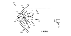
図1Aおよび図1Bは、従来技術による、光トモグラフィの画像を取り込むために用いられる円錐型反射デバイス100を示す。被験体106は、光学的に透明であってもよい台108に支持されている。低パワーレーザなどの照射ビーム104は、110の所で示されているように、円錐ミラー102による反射によって被験体106の表面の上の多くの箇所に導かれるが、ここでは一箇所における照射が図示されている。光は被験体106を通り抜けるが、112において示されているように内部で散乱する。透過光114は、円錐ミラー102によって反射し(116)、118の所で示されているように被験体を照射し得る。このことは、当然ながら多くの箇所で生じ、後方散乱光による被験体106の拡散照射をもたらす。図1Bに示されているように、最初の照射ビームは、ミラー102によって直接的に後方散乱するか(126)、または間接的に後方散乱して(130、132)、134、136などの様々な箇所で被験体106を照射する正反射光124をもたらし得る。図1Aに示されている透過光による後方照射は、概して重大な問題ではない。これは、照射光が被験体を通り抜ける際に散乱するとともに吸収によって減衰するためである。反射光による後方照射は、図1Bに示されているように一般に強力である。このため、一次、二次、または三次(等)の反射光が、被験体とミラーとの間を行ったり来たりし、かつ/または、被験体が測定データに著しい影響を及ぼし得る。
1A and 1B show a conical
図1Aおよび図1Bに示されているように、被験体106が高反射性の円錐ミラーの内側に置かれ、その円錐ミラーによってソース光が被験体の表面に照射されるため、再構成に負の影響のある、被験体の表面と円錐ミラーとの間の後方反射が生じる。このことは、データ計測と、再構成の結果とにおける正確さと精度とを低下させ得る。開示される主題は、この影響を低減し、光イメージングシステムと他の撮像手段(modality)との組み合わせに向けた柔軟性を提供するものである。本開示では、限定されないが、例として、小動物(たとえば、マウスまたはラット)、手、足、または、ヒトの胸部などの体の部位である被験体から非接触である多方向の光トモグラフィのデータを取得するためのイメージングシステムが説明される。
As shown in FIGS. 1A and 1B, the
図2に示されているように、イメージング方式は、いくつかの実施形態では2つの連続したミラーによる反射を用いる。被験体の近くにある第1のミラー204が、その被験体202の表面画像を第2のミラー206に反射し、第2のミラー206が、その画像をCCDカメラ210に反射することによって、反射したすべての画像が一枚の写真として得られる。このように、ビーム208で示されている、被験体202の表面からの最初の透過光または反射光(表面における様々な箇所において光が複数の方向に同時に発生または反射すると理解されたい)が第1のミラー(または、第1の複数のミラー)204によって第2のミラー206に反射し、それによって光212がカメラ210の方に導かれる。ミラー204および206は、たとえば環状の円錐部分でもよく、または、角錐状のものであってもよく、または、不連続性を有するか、もしくは不連続性を有していない部分的に円錐状のものでもあってもよく、または、複数の角度の光を反射し得る、完全もしくは部分的な一周構造からなるいかなる種類のものであってもよい。
As shown in FIG. 2, the imaging scheme uses reflection by two successive mirrors in some embodiments. A
コントローラ214は、レーザなどの照射光源209と、カメラ201および210とを制御することができる。コントローラ214は、カメラ201および210から画像データを受信することができる。カメラ210は、被験体202の表面におけるすべての画像を取り込むために用いられてもよい。カメラ210のCCDへの表面の投射は歪むことになるが、予測できる形で歪み、表面部分の3次元モデル(メッシュ)に対する、被験体202の表面部分ごとの、表面から放出する光子束の計算は、その系の形状がわかっているためにコントローラ214において非常に正確に行われ得る。カメラ201は、被験体202のモデリングに向けて、被験体202の精密な表面形状を取り込むために用いられてもよい。光源209は、被験体202の形状に応じて様々な位置に位置決めされ得る。光源209は、様々な方向を向く被験体202の部分を照射するために、回転または移動可能なガントリーに支持されていてもよい。また複数の光源209が、代替的または付加的に用いられてもよい。
The
図2の反射方式における配置は、被験体202の形状に応じて変更されてもよい。第1および第2のミラーの形状は、被験体の表面形状に応じて平面でもよく、または円錐でもよく、または平面と円錐の形状の組み合わせでもよい。たとえば、いくつかの実施形態では、図4に示されているとともに以下で説明される円錐ミラーのペアが用いられる。この円錐ミラーのペアは、小動物のイメージングに適し得る。平面ミラー方式は、図5Bに示されているとともに以下で説明されるように、手や足などの比較的平らな体の部位のイメージングに用いられ得る。また、たとえば胸部面をイメージングするために、図3に示されているとともに以下で説明される、平面ミラーと円錐ミラーの組み合わせが用いられてもよい。カメラ201は、いくつかの実施形態では、トモグラフィのデータを生成するために、さらなる表面光子放出データなどの他の役割を果たしてもよい。図2に関して説明されたコントローラ、複数のカメラ、および照射光源の特徴は、本明細書で説明される他の実施形態において提供されてもよい。
The arrangement in the reflection method of FIG. 2 may be changed according to the shape of the subject 202. The shape of the first and second mirrors may be a plane, or a cone, depending on the surface shape of the subject, or a combination of a plane and a cone shape. For example, in some embodiments, a pair of conical mirrors as shown in FIG. 4 and described below is used. This pair of conical mirrors may be suitable for small animal imaging. The planar mirror method can be used for imaging relatively flat body parts such as hands and feet, as shown in FIG. 5B and described below. Also, for example, to image the chest surface, a combination of a plane mirror and a conical mirror as shown in FIG. 3 and described below may be used. The
図3Aおよび図3Bは、平面および湾曲面を含む第1および第2の反射器面を有するイメージングデバイス300を示す。平面ミラー308および314は、一次反射器の一部を形成しており、その平面部分308には円錐部分306が隣接している。また二次反射器も、平面部分と湾曲部分とから構成されている。平面部分304は円錐部分312に隣接している。平面状の支持物310は、両胸部間の光のクロストークを抑えるために光吸収性であってもよい。一次反射器は、単体である中空の硬質構造体302に支えられることによって、その構造体302に支えられた反射面の剛性と正確な位置とを可能にしてもよい。構造体303の場合も同様である。二次反射器は、代替実施形態では、反射面、カメラ、および被験体の向きが適切な状態で、一次反射器によって囲まれた空間の外側に配置されていてもよい点に留意されたい。
3A and 3B illustrate an
イメージングデバイス300は、一方または両方の胸部を同時にイメージングするために用いられてもよい。対象となる胸部は、図の位置から見て装置300の後ろに位置決めされるとともに装置300と対向していてもよい。この向きは、被験体からの光がまず反射器306、314、および308に当たり、次に、図を見ている人の位置に対して装置300の左側にあるカメラに導かれるように反射器304、311、および312に当たる向きである。この装置300は、いくつかの実施形態では、図3Bに示されているように、胸部352が下方に突き出る開口部を有するとともに患者348を支えるベッド358の下方で、システム350によって水平の向きに位置決めされてもよい。反射器356は、カメラ354が水平方向に位置決めされることを可能にし得る。
The
図4では、装置400は、図3の装置より低いアスペクト比のイメージングデバイスである。単一の円錐部は一次反射面416を画定し、単一の円錐反射器414は二次反射器を画定している。被験体は、図を見ている人の位置から見て装置400の後ろに位置決めされ、カメラは、図を見ている人の位置から見て装置400の前に位置決めされる。スポーク418は、二次反射器414を支えることができ、一次反射器416および二次反射器414の両方は、表面の剛性と正確な位置とを可能にする中空構造体であってもよい硬質フレーム418に支えられていてもよい。スポーク418は、二次反射器を固定して保持するために張力がかけられていてもよく、二次反射器414の向きの調整を可能にしてもよい。また、これらのスポークは、二次反射器の向きを決める調整可能ねじなどの、シャーシ調整用の留め具を支える硬質構造体であってもよい。この装置400は、図5Aに示されているように小動物のイメージングシステムに用いられてもよく、または人体構造のイメージングに用いられてもよい。
In FIG. 4, the
図5Aを参照すると、小動物のイメージングシステムは、第1の円錐反射器514と、第2の円錐反射器516とを含み得る。動き制御装置は、(表面形状の取得用にカメラも含み得る)照射光源504と、小動物などの被験体512との相対的な移動を提供し得る。第1の動き軸は、カメラおよび/または照射光源504を位置決めするために支持アーム506を回転させるドライブ508を有し得る。第2のドライブ511は、被験体512を動かすために台515を位置決めし得る。被験体および/またはイメージング素子の相対的な移動を提供するための他の構成も可能であり、この図は単なる例を示すものである。円錐ミラーのペアとCCDカメラとによって小動物の表面の光子が計測され、回転ガントリーと、直線的に平行移動する台とからなる動き制御部を用いることによって、被験体の表面のあらゆる領域がピンポイントのレーザ光源によって照射され得る。
Referring to FIG. 5A, the small animal imaging system may include a first
図5Bを参照すると、イメージングデバイス531は、第1および第2の反射器を画定している平面反射器542および540を有している。これらの反射器の構成では、足首の部分536などの比較的平らな表面部分のイメージングに適した左右対称の配置が定められている。構造体534は光源を支持し、光源の平行移動または他の動きをもたらし得る。台は、(1つもしくは複数の)光源による照射、もしくは拡散透過光の受光を可能にする開口部または窓532を提供し得る。
Referring to FIG. 5B, the
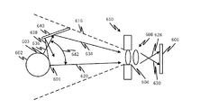
図6Aを参照すると、一般的なカメラの構成において、イメージングされている被験体602における任意の箇所601から発散している光線620が、カメラ610の光学部品608によって(矢印622によって示されているように)再度集束しており、それによって、それらの光線がCCDなどの感光面606における共通の点に注がれている。カメラ610は、被験体の他に、被験体602の周囲の領域の一部を取り込み得る視野616を有し得る。図6Bに示されているように、被験体における箇所601から離れた箇所603からの、光線620から大きい角度642だけ発散する光線636は、ミラー640などの光学素子を特定の向きと場所に配置することにより、経路634に沿ってカメラの方に向けることができ、それによってこの光線は感光面606の別の部分に導かれる(630)。また同時に、光学素子640の角度と位置は、光線638などの、被験体表面における実質的に任意の点からの光が依然として被験体602から離れた方に向けられるようになっている。
Referring to FIG. 6A, in a typical camera configuration, rays 620 emanating from any
図6Bの構成では、光学素子640がない場合にはカメラ610の取込み開口部604に入ることのない2つの光線の発散角が、両方の光線620および634がカメラの取込み開口部604の中に入るように小さくなっている。このことは、別の方向に向いている被験体602の複数の面が単一の撮像面にイメージングされることを可能にする。また、図6Bに示されている実施形態は、これまでの実施形態における利点のいくつかが、直列である複数の方向変更素子以外の光学素子によって一回の方向変更で実現され得るということを示している。
In the configuration of FIG. 6B, the divergence angles of two rays that do not enter the
図7Aを参照すると、小動物のイメージングシステムは、第1の円錐反射器714と第2の円錐反射器716とを有する、図4の装置400と同様に構成されたイメージング素子を含み得る。動き制御装置は、被験体の台715に対する照射光源704の相対的な変位をもたらし得る。被験体712は、透明であってもよい台715の上に示されている。被験体712は小動物でもよい。第2の照射光源703は、図7Aに直交しているとともに図7Bの面に平行な角度を通じてスキャンするラインスキャナでもよい。このラインスキャナは、被験体712に向けられたカメラ721に被験体712の形状をはっきりと示す走査線を作り出すために用いられてもよい。
Referring to FIG. 7A, a small animal imaging system may include an imaging element configured similar to the
ミラーのペア725は、図7Bに最も良く示されているように、たとえば90度から120度離れて、互いに対して傾いて位置決めされている。これらのミラー725は、被験体712の背面と側面をカメラ721に反映し、被験体712の表面モデルを作り出して、トモグラフィのデータ生成に適したメッシュの生成を可能にするために公知の技術を用いて処理され得るオーバーラップデータ(overlapping data)を提供する。ドライブ729は、照射光源704を被験体712の周りの任意の方向に位置決めするために回転リング728を回転させる。第2のリニアドライブ727は、ミラーのペア725と2つのカメラ721とからなるプラットフォーム726を表面スキャンに向けて位置決めする。このプラットフォーム726は、表面スキャンの後にリニアドライブ727によって横方向に動かされてもよい。また光源704は、トモグラフィのデータ収集に向けて光源の位置を選択するために、プラットフォーム726が動かされた後に回転ドライブ729によって連続的な回転位置に導かれてもよい。イメージング素子の相対的な移動を行うための他の構成も可能であり、図は単なる例を提供するものである。円錐ミラーのペア701とCCDカメラ712とによって、第1および第2のドライブのそれぞれの位置と照射光源704とによって生成される、点光源ごとの、小動物の表面全体からの光子が計測される。
The mirror pairs 725 are tilted and positioned relative to each other, for example 90 to 120 degrees apart, as best shown in FIG. 7B. These
説明されたシステムでは、被験体の表面全体が単一の円錐ミラー方式と同様に観測され得るが、これは、被験体がミラーペア構造体の外側に置かれ、不要な後方反射の影響が低減され得るためである。さらに、被験体の周りの空きスペースを利用することにより、CTまたはPETなどの他の撮像手段が、被験体の周りのミラー構造体によって妨げられることなく、この光イメージングシステムと組み合わされてもよい。 In the described system, the entire surface of the subject can be observed in the same way as a single cone mirror scheme, but this places the subject outside the mirror pair structure and reduces the effects of unwanted back reflections. To get. Furthermore, by utilizing the free space around the subject, other imaging means such as CT or PET may be combined with this optical imaging system without being disturbed by the mirror structure around the subject. .
開示された実施形態のいずれにおいても、光源は、DLPタイプのスキャナを用いてスキャンしてもよく、または、他の好適な任意の向き決め機構を用いてスキャンしてもよい。実施形態のいずれにおいても、被検体は、被検体および/または光源の相対的な移動を行うことによってスキャンされてもよい。実施形態のいずれにおいても、円筒形の光学面と平らな光学面とは、画像を生成し得る非円筒形の面、および平らでない面、ならびに3次元の湾曲部分に置き換えられてもよい。実施形態のいずれにおいても、表面形状は、多視点表面イメージング(multiple−vantage surface imaging)以外のレーザスキャン、または他の任意の手段によって取得されてもよい。開示された実施形態のいずれにおいても、ミラー以外の反射を実現するためにプリズムなどの屈折デバイスが用いられてもよい。実施形態のいずれにおいても、ミラーは、被検体における一部またはすべての表面を有効とするために、湾曲面以外の多数の切り子面を含み得る。 In any of the disclosed embodiments, the light source may be scanned using a DLP type scanner, or may be scanned using any other suitable orientation mechanism. In any of the embodiments, the subject may be scanned by performing relative movement of the subject and / or the light source. In any of the embodiments, the cylindrical and flat optical surfaces may be replaced with non-cylindrical surfaces that can produce images, and non-planar surfaces, and three-dimensional curved portions. In any of the embodiments, the surface shape may be obtained by laser scanning other than multiple-vantage surface imaging, or any other means. In any of the disclosed embodiments, refractive devices such as prisms may be used to achieve reflections other than mirrors. In any of the embodiments, the mirror may include a number of facets other than a curved surface in order to validate some or all surfaces on the subject.
開示された実施形態のいずれにおいても、開示されたイメージングデバイスは、トモグラフィの再構成に用いられる点照射とカメラによるイメージングの代わりに、表面モデルを作り出すために複数の画像を用いるか、またはレーザスキャンを用いるか、または任意の他の手段を用いることによる、表面の取得に用いられてもよい。 In any of the disclosed embodiments, the disclosed imaging device uses multiple images or lasers to create a surface model instead of point illumination and camera imaging used for tomographic reconstruction. It may be used for surface acquisition by using a scan or by using any other means.
いくつかの実施形態によれば、開示される主題にはイメージングシステムが含まれる。本システムは、被検体を保持するように構成された被検体支持物を有する。被検体自体はイメージングシステムの一部ではない。本システムは、第1の光学素子を有しており、この第1の光学素子は、上記支持物の上に位置決めされた被検体からの光を受光するとともに、受光した光を別の方向に向けることによってその光の方向を第2の光学素子に向けて変更するように構成および位置決めされている。光学素子は、光ファイバー、すなわち、電子信号への変換によってではなく、空気経路によって光を導くために、反射または屈折によってこのことを行う。このように方向を変更することは、たとえば、被検体における互いに反対側の位置からの光をイメージングデバイス(たとえばカメラ)の方へ反射することによって、被検体における複数の面のイメージングを効果的に可能にし、それにより、カメラによる被検体の複数の成分冗長のビュー、または部分的に成分冗長のビューが生み出される。反射波のコサイン圧縮に基づく入射角の広さと、忠実度における損失の低さとを可能にするため、光学素子には直列である複数の反射器が用いられてもよい。 According to some embodiments, the disclosed subject matter includes an imaging system. The system includes a subject support configured to hold a subject. The subject itself is not part of the imaging system. The system has a first optical element. The first optical element receives light from a subject positioned on the support and transmits the received light in another direction. And is configured and positioned to change the direction of the light toward the second optical element by directing. The optical element does this by reflection or refraction to direct the light through the air path rather than by conversion to an optical fiber, ie an electronic signal. Changing the direction in this way effectively images multiple surfaces on the subject, for example, by reflecting light from opposite positions on the subject toward the imaging device (eg, camera). Enabling, thereby producing multiple, or partially, component-redundant views of the subject by the camera. In order to allow a wide angle of incidence based on cosine compression of the reflected wave and low loss in fidelity, a plurality of reflectors in series may be used in the optical element.
また本システムは、上記被検体支持物の上に置かれた被検体が複数の側から照射され得るよう、様々な角度の光線を上記被検体支持物の方に導くように構成された照射光源を有し得る。この照射光源は、高速検査システムで使用されている、被検体の3次元モデルを生成するために用いられるレーザ・スポット・スキャンまたはレーザ・ライン・スキャンなどの表面スキャンに用いられてもよい。この照射光源、または別の照射光源は、光トモグラフィにおける用途に向け、周期的かつ多様に位置している被検体表面の放出源、または、被検体内部の深い所にある放出源を作り出すために用いられてもよい。また本システムは、たとえば被検体内部における光源(生物発光の光源)の分布をトモグラフィによって求めることに用いられる場合には、照射光源を使用せずに用いられてもよい。 In addition, the system includes an irradiation light source configured to guide light beams at various angles toward the subject support so that the subject placed on the subject support can be irradiated from a plurality of sides. Can have. This irradiation light source may be used for surface scanning such as laser spot scanning or laser line scanning used to generate a three-dimensional model of an object used in a high-speed inspection system. This illumination source, or another illumination source, is used to create periodic and diversely located subject surface emitters or emitters deep within the subject for use in optical tomography May be used. Further, the present system may be used without using an irradiation light source, for example, when it is used for obtaining a distribution of a light source (bioluminescent light source) in a subject by tomography.
最終的には、上記のいくつかの実施形態の特徴のうちの1つは、光学素子が、被検体に戻る光の反射を避ける方向に光を導くということである。たとえば、被検体表面に向けられたレーザスポットなどの光源によって表面の放出源が生成される場合には、その表面から大量の光が反射する。光学素子のいずれの部分も反射器を有しており、また反射器のいずれの部分も、レーザスポットから拡散反射された光線を反射し得る場合、このことは、被検体に、より多くの照射をもたらすことになる。このことは、検査されている被検体の内部特性をイメージングするために用いられる光トモグラフィの信号を劣化させる可能性がある。生物発光トモグラフィの場合と同様に、被検体の外に透過した光であっても、光学素子から表面などに「再び戻るように反射する」場合がある。したがって、光学素子のうちの第1の光学素子は、被検体支持物の上の被検体からの光の鏡面反射光または屈折光が上記被検体支持物の上の被検体から離れる方に導かれ、それにより、上記被検体の表面から放出された光子による、被検体における二次照射が防止され得るように上記被検体支持物に対して位置決めされ得る。第2の素子は、反射光を撮像カメラの視野の中に導くことを可能にし得る。 Ultimately, one of the features of some of the embodiments described above is that the optical element directs light in a direction that avoids reflection of light back to the subject. For example, when a surface emission source is generated by a light source such as a laser spot directed at the subject surface, a large amount of light is reflected from the surface. If any part of the optical element has a reflector, and any part of the reflector can reflect the light diffusely reflected from the laser spot, this means more radiation to the subject. Will bring. This can degrade the optical tomography signal used to image the internal characteristics of the subject being examined. Similar to the case of bioluminescence tomography, even light transmitted outside the subject may be “reflected to return again” from the optical element to the surface or the like. Therefore, the first optical element of the optical elements is guided in a direction in which the specular reflection light or the refracted light from the subject on the subject support is separated from the subject on the subject support. Thereby, it can be positioned with respect to the object support so that secondary irradiation in the object due to photons emitted from the surface of the object can be prevented. The second element may allow the reflected light to be guided into the field of view of the imaging camera.
第1の光学素子は、いくつかの実施形態では、被検体における複数の反対側の面からの光を受光するように構成されている。第2の素子は、カメラによる取り込みに向けて画像をそろえるために用いられる。第1および第2の光学素子の組は、平面ミラーおよび/または円錐ミラーの組み合わせを含み得る。被検体を部分的に囲うために、たとえば角錐または円錐の構成が用いられてもよい。 In some embodiments, the first optical element is configured to receive light from a plurality of opposite surfaces of the subject. The second element is used to align the images for capture by the camera. The first and second set of optical elements may include a combination of plane mirrors and / or conical mirrors. For example, a pyramid or cone configuration may be used to partially enclose the subject.
本システムは、一実施形態として、ユーザが自身のカメラを提供することを可能にするシステムの一部として、カメラを含んでいても含んでいなくてもよい。いくつかの実施形態では、カメラはシステムの一部として含まれている。他の実施形態では、カメラのないシステムがユーザによるカメラと共に用いられ、それにより、本システムはカメラなしで提供されるが、カメラ用の標準的な取り付け台や位置決め台を含んでいてもよい。この台は、上記の特徴を実現するためにカメラの視野を適切にそろえるよう、光学素子に対するカメラの位置決めを可能にし得る。 The system, as an embodiment, may or may not include a camera as part of a system that allows a user to provide their own camera. In some embodiments, the camera is included as part of the system. In other embodiments, a cameraless system is used with a camera by a user, whereby the system is provided without a camera, but may include a standard mounting or positioning platform for the camera. This platform may allow the camera to be positioned relative to the optical element so as to properly align the camera's field of view to achieve the above features.
イメージングシステムには、トモグラフィのデータ構築を可能にするコントローラおよび/またはコンピュータが提供され得る。また本システムは、発色団の分布における3次元ビューなどの、トモグラフィによる構築結果を提示するためのディスプレイを含み得る。 The imaging system may be provided with a controller and / or computer that allows tomographic data construction. The system may also include a display for presenting tomographic construction results, such as a three-dimensional view of the chromophore distribution.
このように、光トモグラフィに向けた光学的方法、デバイス、およびシステムが本開示に従って提供されることは明白である。本開示により、多くの代替形態、変形形態、および変更形態が可能である。開示された実施形態の特徴は、さらなる実施形態を生み出すために、本発明の範囲内において、組み合わせ、再構成、省略等がなされてもよい。さらに、いくつかの特徴は、場合によっては、有利となるように他の特徴を使用せずに用いられてもよい。このように、出願人らは、本発明の趣旨および範囲に含まれるすべての代替形態、変形形態、等価物、および変更形態の包含を意図している。
Thus, it will be apparent that optical methods, devices, and systems for optical tomography are provided in accordance with the present disclosure. Many alternatives, variations, and modifications are possible with the present disclosure. The features of the disclosed embodiments may be combined, reconfigured, omitted, etc. within the scope of the present invention to yield further embodiments. In addition, some features may be used without the use of other features in some cases. As such, applicants intend to embrace all alternatives, modifications, equivalents, and variations that fall within the spirit and scope of the present invention.
Claims (51)
前記被検体支持物の上に位置決めされた被検体からの光を受光するとともに、前記受光した光を別の方向に向けることによって前記受光した光の方向を第2の光学素子に向けて変更するように位置決めされた第1の光学素子と、
前記被検体支持物の上に置かれた被検体が複数の側から照射されるように様々な角度の光線を前記被検体支持物の方に導くように構成された照射光源と、
を備えるイメージングシステムであって、
前記第2の光学素子が、前記第1の光学素子から受光した光の方向をイメージングデバイスの方に変更するように配置され、
前記第1および前記第2の光学素子が鏡面反射または屈折を行い、
前記第1の光学素子が、前記被検体における複数の反対側の面からの前記光を受光するように構成され、
前記被検体支持物の上の被検体からの光の鏡面反射光または屈折光が前記被検体支持物の上の被検体から離れる方に導かれ、それによって、前記被検体の表面から放出される光子による被検体の二次照射が防止されるように、前記第1の光学素子が前記被検体支持物に対して位置決めされている、イメージングシステム。 Subject support;
While receiving light from a subject positioned on the subject support, the direction of the received light is changed toward the second optical element by directing the received light in another direction. A first optical element positioned as follows:
An illumination light source configured to guide light beams of various angles toward the subject support so that the subject placed on the subject support is illuminated from a plurality of sides;
An imaging system comprising:
The second optical element is arranged to change the direction of light received from the first optical element to an imaging device;
The first and second optical elements perform specular reflection or refraction;
The first optical element is configured to receive the light from a plurality of opposite surfaces of the subject;
Specular or refracted light from the subject on the subject support is guided away from the subject on the subject support, and is thereby emitted from the surface of the subject. An imaging system, wherein the first optical element is positioned with respect to the subject support so that secondary irradiation of the subject by photons is prevented.
前記被検体から離れた前記光線を光学素子を用いて導き、前記光線の一部の方向を変更するステップであって、それにより、前記光線が前記被検体の表面を再度照射することが防止される、ステップと
を含む、拡散光トモグラフィのデータを生成するための方法であって、
前記光線を導くステップが、前記光線の一部を、イメージングされることになる光が通る視野を有するイメージングデバイスに導くステップを含み、
前記光線を導くステップが、別の方向に向いている前記被検体の表面の部分の画像を取り込めるように前記光線の一部が前記視野の中に導かれるよう、前記光線の一部が前記被検体の表面を離れる際に発散する方向を変更するステップをさらに含む、方法。 The light beam emits a photon into the subject, the photon leaves the subject after being scattered or absorbed inside the subject, and the reflected light leaves the surface of the subject. Directing the light rays to the surface of the subject, whereby reflected or transmitted light rays leave the subject surface from respective locations in the subject; and
Guiding the light beam away from the subject using an optical element and changing the direction of a part of the light beam, thereby preventing the light beam from irradiating the surface of the subject again. A method for generating diffuse optical tomography data comprising the steps of:
Directing the light beam comprises directing a portion of the light beam to an imaging device having a field of view through which the light to be imaged passes;
A portion of the light beam is guided into the field of view such that the step of directing the light beam captures an image of a portion of the surface of the subject facing in another direction. Changing the direction of divergence upon leaving the surface of the specimen.
前記被検体支持物の上に位置決めされた被検体からの光を受光するとともに、受光した光を別の方向に向けることによって、前記受光した光の方向を、視野を有するイメージングデバイスに向けて変更するように位置決めされた第1の光学素子と、
前記被検体支持物の上に置かれた被検体が複数の側から照射されるように様々な角度の光線を前記被検体支持物の方に導くように構成された照射光源と
を備えるイメージングシステムであって、
前記被検体支持物の上の被検体からの光の鏡面反射光または屈折光が前記被検体支持物の上の被検体から離れる方に導かれ、それによって、前記被検体の表面から放出される光子による被検体の二次照射が防止されるように、前記第1の光学素子が前記被検体支持物に対して位置決めされ、
前記被検体支持物から離れる方に向けられた、前記第1の光学素子によって受光される第1の光線と第2の光線との間の角度を狭くするように前記第1の光学素子が構成され、それによって、前記第1および前記第2の光線が前記視野の中に導かれ得る、イメージングシステム。 Subject support;
Receiving light from a subject positioned on the subject support and directing the received light in a different direction to change the direction of the received light toward an imaging device having a field of view A first optical element positioned to
An imaging system comprising: an irradiation light source configured to guide light beams of various angles toward the object support so that the object placed on the object support is irradiated from a plurality of sides Because
Specular or refracted light from the subject on the subject support is guided away from the subject on the subject support, and is thereby emitted from the surface of the subject. The first optical element is positioned relative to the subject support so as to prevent secondary irradiation of the subject by photons;
The first optical element is configured to narrow the angle between the first light beam and the second light beam that are directed away from the object support and received by the first optical element. An imaging system in which the first and second rays can be guided into the field of view.
前記被検体支持物の上に位置決めされた被検体からの光を受光するとともに、受光した光を別の方向に向けることによって、前記受光した光の方向を、視野を有するイメージングデバイスに向けて変更するように位置決めされた第1の光学素子と
を備えるイメージングデバイスであって、
前記第1の光学素子によって受光される、前記被検体支持物の上の被検体からの反対方向に向けられた光が、前記被検体支持物の上の被検体から離れる方に周囲の空気を通じて完全に導かれ、それによって、前記被検体の表面から放出される光子による被検体の二次照射が防止されるようにして、前記第1の光学素子が前記被検体支持物に対して位置決めされ、
前記第1の光学素子が、前記第1の光学素子によって受光された前記光を、イメージングデバイスの視野を画定する領域に導くように構成されている、イメージングデバイス。 Subject support;
Receiving light from a subject positioned on the subject support and directing the received light in a different direction to change the direction of the received light toward an imaging device having a field of view An imaging device comprising: a first optical element positioned to:
The light received by the first optical element and directed in the opposite direction from the subject on the subject support passes through the surrounding air in a direction away from the subject on the subject support. The first optical element is positioned relative to the subject support such that it is completely guided thereby preventing secondary illumination of the subject by photons emitted from the surface of the subject. ,
An imaging device, wherein the first optical element is configured to direct the light received by the first optical element to a region that defines a field of view of the imaging device.
前記台の上に置かれた被検体の直線部分を照射するために前記台を横切るラインを投射するように構成されたラインスキャン用光源と、
前記台に置かれた被検体の表面をスキャンするためにラインスキャン用光源に対して前記台を移動する横方向移動システムと、
前記横方向移動システムに接続されているとともに、前記台の上に置かれた被検体の上に複数の点光源を作り出すように構成された第2の光源と、
前記台の上に置かれた被検体の画像を前記被検体の複数の面から受光するように位置決めされたトモグラフィ画像カメラ、および光イメージング装置と
を備えるイメージングシステム。 A pair of mirrors disposed in the vicinity of the table and facing the table and tilted away to reflect an image of the subject on the table toward the at least one first camera;
A light source for line scanning configured to project a line across the table to illuminate a linear portion of the subject placed on the table;
A lateral movement system that moves the table relative to a light source for line scanning to scan the surface of the subject placed on the table;
A second light source connected to the lateral movement system and configured to create a plurality of point light sources on a subject placed on the table;
An imaging system comprising: a tomographic image camera positioned so as to receive an image of a subject placed on the table from a plurality of surfaces of the subject; and an optical imaging device.
51. The imaging system of claim 50, wherein the translational displacement component is a linear drive that moves the platform.
Applications Claiming Priority (3)
| Application Number | Priority Date | Filing Date | Title |
|---|---|---|---|
| US201161557045P | 2011-11-08 | 2011-11-08 | |
| US61/557,045 | 2011-11-08 | ||
| PCT/US2012/064245 WO2013070982A1 (en) | 2011-11-08 | 2012-11-08 | Systems and methods for simultaneous multi-directional imaging for capturing tomographic data |
Publications (2)
| Publication Number | Publication Date |
|---|---|
| JP2014535056A true JP2014535056A (en) | 2014-12-25 |
| JP2014535056A5 JP2014535056A5 (en) | 2015-12-03 |
Family
ID=48290568
Family Applications (1)
| Application Number | Title | Priority Date | Filing Date |
|---|---|---|---|
| JP2014540233A Pending JP2014535056A (en) | 2011-11-08 | 2012-11-08 | Systems and methods for simultaneous multidirectional imaging for capturing tomographic data |
Country Status (5)
| Country | Link |
|---|---|
| US (1) | US20140330116A1 (en) |
| EP (1) | EP2775923A4 (en) |
| JP (1) | JP2014535056A (en) |
| KR (1) | KR20140098119A (en) |
| WO (1) | WO2013070982A1 (en) |
Families Citing this family (8)
| Publication number | Priority date | Publication date | Assignee | Title |
|---|---|---|---|---|
| US9495516B2 (en) | 2012-11-21 | 2016-11-15 | The Trustees Of Columbia University In The City Of New York | Systems, methods, and devices for image reconstruction using combined PDE-constrained and simplified spherical harmonics algorithm |
| KR101488115B1 (en) | 2013-12-30 | 2015-01-29 | 건양대학교산학협력단 | Compact computer tomography apparatus |
| CN105266815B (en) * | 2015-09-17 | 2017-12-29 | 苏州佳世达光电有限公司 | Electronic installation |
| TWI628428B (en) * | 2016-12-16 | 2018-07-01 | 由田新技股份有限公司 | A multi-angled defect capturing device and a multi-angled defect inspecting apparatus having the same |
| CN111344624B (en) * | 2017-10-18 | 2022-07-15 | 珀金埃尔默健康科学有限公司 | Fast, high dynamic range image acquisition with Charge Coupled Device (CCD) camera |
| US11950881B2 (en) | 2019-07-28 | 2024-04-09 | Holovsions LLC | Smart bra for optical scanning of breast tissue to detect abnormal tissue with selectively-expandable components to reduce air gaps |
| US11304456B2 (en) | 2019-07-28 | 2022-04-19 | Holovisions LLC | Smart bra with optical sensors to detect abnormal breast tissue |
| KR20240027491A (en) * | 2022-08-23 | 2024-03-04 | 주식회사 팀누비즈 | Three-dimensional intraoral scanner implementing stereo optical system using single camera |
Citations (10)
| Publication number | Priority date | Publication date | Assignee | Title |
|---|---|---|---|---|
| JPH04118618A (en) * | 1990-03-29 | 1992-04-20 | Shimadzu Corp | Optical scanner |
| JP2000206411A (en) * | 1999-01-19 | 2000-07-28 | Sharp Corp | Optical device, optical head and information reproducing device using them |
| JP2003084202A (en) * | 2001-09-11 | 2003-03-19 | Miyagi Prefecture | Ultraviolet-area fluorescent microscope, fluorescent material identifying method, and cleaning degree evaluating method |
| JP2004004549A (en) * | 2002-02-04 | 2004-01-08 | Carl-Zeiss-Stiftung Trading As Carl Zeiss | Stereoscopic examination system, stereoscopic image generating apparatus and its operation method |
| JP2006125940A (en) * | 2004-10-27 | 2006-05-18 | Nippon Hoso Kyokai <Nhk> | Photoluminescence quantum yield measurement method and device used therein |
| US20070244395A1 (en) * | 2006-01-03 | 2007-10-18 | Ge Wang | Systems and methods for multi-spectral bioluminescence tomography |
| JP2010091818A (en) * | 2008-10-08 | 2010-04-22 | Olympus Corp | Scanning optical system |
| US20100309566A1 (en) * | 2009-06-05 | 2010-12-09 | CVI Melles Griot, Inc. | Reflective axicon systems and methods |
| US20110096967A1 (en) * | 2008-05-15 | 2011-04-28 | Shimadzu Corporation | Biological Imaging Device |
| US20110226961A1 (en) * | 2010-03-18 | 2011-09-22 | Otsuka Electronics Co., Ltd. | Quantum efficiency measurement method, quantum efficiency measurement apparatus, and integrator |
Family Cites Families (4)
| Publication number | Priority date | Publication date | Assignee | Title |
|---|---|---|---|---|
| US7107116B2 (en) * | 1999-03-29 | 2006-09-12 | Genex Technologies, Inc. | Diffuse optical tomography system and method of use |
| US20080013820A1 (en) * | 2006-07-11 | 2008-01-17 | Microview Technology Ptd Ltd | Peripheral inspection system and method |
| US8014569B2 (en) * | 2006-10-30 | 2011-09-06 | The Regents Of The University Of California | Method and apparatus for performing qualitative and quantitative analysis of produce (fruit, vegetables) using spatially structured illumination |
| TWI479583B (en) * | 2008-04-04 | 2015-04-01 | Nanda Technologies Gmbh | Optical inspection system and method |
-
2012
- 2012-11-08 WO PCT/US2012/064245 patent/WO2013070982A1/en active Application Filing
- 2012-11-08 KR KR1020147015257A patent/KR20140098119A/en not_active Application Discontinuation
- 2012-11-08 US US14/356,932 patent/US20140330116A1/en not_active Abandoned
- 2012-11-08 JP JP2014540233A patent/JP2014535056A/en active Pending
- 2012-11-08 EP EP12847970.6A patent/EP2775923A4/en not_active Withdrawn
Patent Citations (12)
| Publication number | Priority date | Publication date | Assignee | Title |
|---|---|---|---|---|
| JPH04118618A (en) * | 1990-03-29 | 1992-04-20 | Shimadzu Corp | Optical scanner |
| JP2000206411A (en) * | 1999-01-19 | 2000-07-28 | Sharp Corp | Optical device, optical head and information reproducing device using them |
| JP2003084202A (en) * | 2001-09-11 | 2003-03-19 | Miyagi Prefecture | Ultraviolet-area fluorescent microscope, fluorescent material identifying method, and cleaning degree evaluating method |
| JP2004004549A (en) * | 2002-02-04 | 2004-01-08 | Carl-Zeiss-Stiftung Trading As Carl Zeiss | Stereoscopic examination system, stereoscopic image generating apparatus and its operation method |
| JP2006125940A (en) * | 2004-10-27 | 2006-05-18 | Nippon Hoso Kyokai <Nhk> | Photoluminescence quantum yield measurement method and device used therein |
| US20070244395A1 (en) * | 2006-01-03 | 2007-10-18 | Ge Wang | Systems and methods for multi-spectral bioluminescence tomography |
| US20110096967A1 (en) * | 2008-05-15 | 2011-04-28 | Shimadzu Corporation | Biological Imaging Device |
| JPWO2009139058A1 (en) * | 2008-05-15 | 2011-09-15 | 株式会社島津製作所 | Biological imaging device |
| JP2010091818A (en) * | 2008-10-08 | 2010-04-22 | Olympus Corp | Scanning optical system |
| US20100309566A1 (en) * | 2009-06-05 | 2010-12-09 | CVI Melles Griot, Inc. | Reflective axicon systems and methods |
| US20110226961A1 (en) * | 2010-03-18 | 2011-09-22 | Otsuka Electronics Co., Ltd. | Quantum efficiency measurement method, quantum efficiency measurement apparatus, and integrator |
| JP2011196735A (en) * | 2010-03-18 | 2011-10-06 | Otsuka Denshi Co Ltd | Quantum efficiency measurement method, quantum efficiency measurement apparatus and integrator |
Also Published As
| Publication number | Publication date |
|---|---|
| EP2775923A1 (en) | 2014-09-17 |
| EP2775923A4 (en) | 2015-07-15 |
| US20140330116A1 (en) | 2014-11-06 |
| KR20140098119A (en) | 2014-08-07 |
| WO2013070982A1 (en) | 2013-05-16 |
Similar Documents
| Publication | Publication Date | Title |
|---|---|---|
| JP2014535056A (en) | Systems and methods for simultaneous multidirectional imaging for capturing tomographic data | |
| US10130318B2 (en) | Integrated microtomography and optical imaging systems | |
| JP4672260B2 (en) | Imaging device | |
| JP6701307B2 (en) | Object information acquisition apparatus and method for controlling object information acquisition apparatus | |
| US9709733B2 (en) | Hand-held optical probe based imaging system with 3D tracking facilities | |
| US9635349B2 (en) | Second generation hand held optical imager | |
| JP6587385B2 (en) | Subject information acquisition apparatus and subject information acquisition method | |
| US6992762B2 (en) | Method and apparatus for time resolved optical imaging of biological tissues as part of animals | |
| JP2006505804A6 (en) | Method and apparatus for time-resolved optical imaging of biological tissue as part of an animal | |
| US10674918B2 (en) | Near-infrared (NIR) optical scanner | |
| JP7229705B2 (en) | Method for determining x-ray scan geometry and method for acquiring x-ray images | |
| EP1968431A2 (en) | Combined x-ray and optical tomographic imaging system | |
| CA3070269C (en) | Systems and methods for rapid wide field illumination scanning for in vivo small animal fluorescence tomographic imaging | |
| JP2015085200A (en) | Examination site information acquisition apparatus | |
| US6901131B2 (en) | Methods and apparatus for computed tomography imaging | |
| CN105361840A (en) | Photoacoustic endoscope system | |
| JP2013103021A (en) | Acoustic wave acquisition device and control method of the same | |
| US20040220479A1 (en) | Folded optics in a laser imaging apparatus with an ergonometric tabletop | |
| JP2006071472A (en) | Ct method and ct apparatus | |
| JP3505609B2 (en) | Optical CT imaging device | |
| CN115919265A (en) | Near-infrared blood vessel imaging method and device | |
| CN117582239A (en) | System and method for combining LiDAR-based techniques with computed tomography systems | |
| CN116839500A (en) | Imaging system for simultaneously extracting internal fluorescent molecular distribution and surface three-dimensional structure | |
| Lee et al. | A Fast full-body fluorescence/bioluminescence imaging system for small animals | |
| JP2006305300A (en) | Signal processing method and apparatus, and x-ray ct apparatus |
Legal Events
| Date | Code | Title | Description |
|---|---|---|---|
| A521 | Request for written amendment filed |
Free format text: JAPANESE INTERMEDIATE CODE: A523 Effective date: 20151013 |
|
| A621 | Written request for application examination |
Free format text: JAPANESE INTERMEDIATE CODE: A621 Effective date: 20151013 |
|
| A977 | Report on retrieval |
Free format text: JAPANESE INTERMEDIATE CODE: A971007 Effective date: 20160824 |
|
| A131 | Notification of reasons for refusal |
Free format text: JAPANESE INTERMEDIATE CODE: A131 Effective date: 20161004 |
|
| A02 | Decision of refusal |
Free format text: JAPANESE INTERMEDIATE CODE: A02 Effective date: 20170425 |