JP2014533591A - Product display and loading system - Google Patents
Product display and loading system Download PDFInfo
- Publication number
- JP2014533591A JP2014533591A JP2014543606A JP2014543606A JP2014533591A JP 2014533591 A JP2014533591 A JP 2014533591A JP 2014543606 A JP2014543606 A JP 2014543606A JP 2014543606 A JP2014543606 A JP 2014543606A JP 2014533591 A JP2014533591 A JP 2014533591A
- Authority
- JP
- Japan
- Prior art keywords
- product
- loading
- shelf member
- product display
- dispenser
- Prior art date
- Legal status (The legal status is an assumption and is not a legal conclusion. Google has not performed a legal analysis and makes no representation as to the accuracy of the status listed.)
- Pending
Links
Images


Classifications
-
- A—HUMAN NECESSITIES
- A47—FURNITURE; DOMESTIC ARTICLES OR APPLIANCES; COFFEE MILLS; SPICE MILLS; SUCTION CLEANERS IN GENERAL
- A47F—SPECIAL FURNITURE, FITTINGS, OR ACCESSORIES FOR SHOPS, STOREHOUSES, BARS, RESTAURANTS OR THE LIKE; PAYING COUNTERS
- A47F5/00—Show stands, hangers, or shelves characterised by their constructional features
- A47F5/0018—Display racks with shelves or receptables
- A47F5/0025—Display racks with shelves or receptables having separate display containers or trays on shelves or on racks
-
- A—HUMAN NECESSITIES
- A47—FURNITURE; DOMESTIC ARTICLES OR APPLIANCES; COFFEE MILLS; SPICE MILLS; SUCTION CLEANERS IN GENERAL
- A47F—SPECIAL FURNITURE, FITTINGS, OR ACCESSORIES FOR SHOPS, STOREHOUSES, BARS, RESTAURANTS OR THE LIKE; PAYING COUNTERS
- A47F1/00—Racks for dispensing merchandise; Containers for dispensing merchandise
- A47F1/04—Racks or containers with arrangements for dispensing articles, e.g. by means of gravity or springs
- A47F1/08—Racks or containers with arrangements for dispensing articles, e.g. by means of gravity or springs dispensing from bottom
- A47F1/087—Racks or containers with arrangements for dispensing articles, e.g. by means of gravity or springs dispensing from bottom the container having approximately horizontal tracks of the serpentine type
Landscapes
- Freezers Or Refrigerated Showcases (AREA)
- Details Of Rigid Or Semi-Rigid Containers (AREA)
- Vending Machines For Individual Products (AREA)
Abstract
製品陳列及び装填システム(10)は、前端及び後端を有する略水平棚部材(34)を含む棚組立体(12)と、棚部材上に設置された製品ディスペンサ(14)と、を含み、製品ディスペンサは、前端に隣接する装填面(20)を規定するために前端から間隔をあけられている。The product display and loading system (10) includes a shelf assembly (12) including a generally horizontal shelf member (34) having a front end and a rear end, and a product dispenser (14) installed on the shelf member, The product dispenser is spaced from the front end to define a loading surface (20) adjacent to the front end.
Description
(関連出願の参照)
本出願は、米国特許法第119条(e)の下で、2011年11月29日付けで出願された米国特許出願番号第13/306,126号の優先権を主張するもので、該出願は、その全体において参照することによって本明細書に組み込まれる。
(Refer to related applications)
This application claims priority from US Patent Application No. 13 / 306,126, filed November 29, 2011 under 35 USC 119 (e). Are hereby incorporated by reference in their entirety.
本出願は、店頭での陳列部、より具体的に、製品を消費者に対して陳列するためのシステム及び方法に関する。 This application relates to storefront displays, and more specifically to systems and methods for displaying products to consumers.
通常、製品は、多数の個々のまとまった製品を容器、例えばカートンまたはボックス内に収納することによってまとめて小売業者へ出荷される。例えば、缶詰食品は、24個の個々の缶を収容するボックスで小売業者へ出荷される。そして、通常、個々のまとまった製品を容器から取り出し、消費者が製品を取ることができる陳列部、例えば棚上で製品を見せることが小売業者の習慣である。 Typically, products are shipped together to retailers by storing a large number of individual products in containers, such as cartons or boxes. For example, canned food products are shipped to retailers in boxes containing 24 individual cans. And it is customary for retailers to usually take individual bundled products out of the container and show the products on a display, such as a shelf, where consumers can pick up the products.
作業効率を向上させるための取り組みとして、従来の梱包−出荷−開梱−陳列モデルとは異なるモデルが発展してきている。例として、(2011年4月12日付けで公開された)特許文献1は、支持構造体、製品陳列エリア及び開放ツールを有するディスペンサを含む製品分配システムを開示している。ディスペンサは、小売業者の棚上に設置されており、ディスペンサには、多数のまとまった製品を備える容器をディスペンサの支持構造体上に置くことによって製品が容易に装填される。容器が支持構造体上に置かれると、ディスペンサの開放ツールは、製品が重力を受けて容器からディスペンサの製品陳列エリアへ転がり落ちるように容器を開ける。 As an effort to improve work efficiency, a model different from the conventional packing-shipping-unpacking-display model has been developed. By way of example, US Pat. No. 6,057,031 (published April 12, 2011) discloses a product dispensing system that includes a dispenser having a support structure, a product display area, and an opening tool. The dispensers are installed on the retailer's shelves, and the dispensers are easily loaded with products by placing a container comprising a number of bundled products on the support structure of the dispenser. When the container is placed on the support structure, the dispenser opening tool opens the container so that the product is subjected to gravity and rolls down from the container to the product display area of the dispenser.
このように、製品分配システムは、製品陳列エリアを含み、消費者は、製品陳列エリアから製品を容易に取ることができる。1つの製品が製品陳列エリアから取り出されると、ディスペンサ内の別の製品が重力を受けて製品陳列エリアへ移動する。従って、消費者は、単一の製品分配システムから多数の製品を取ることができる。 In this manner, the product distribution system includes a product display area, and a consumer can easily take a product from the product display area. As one product is removed from the product display area, another product in the dispenser receives gravity and moves to the product display area. Thus, consumers can take multiple products from a single product distribution system.
さらに、多数の製品分配システムが単一の陳列部上に設置されてもよい。各製品分配システムには、異なる製品が装填され、それにより、消費者にさまざまな製品の選択を提供することができる。さらなる製品分配システムが、人気のある製品を分配するために使用され、それにより、人気のある製品の供給力を増大させることもできる。 In addition, multiple product distribution systems may be installed on a single display. Each product dispensing system is loaded with a different product, thereby providing the consumer with a variety of product choices. Additional product distribution systems can also be used to distribute popular products, thereby increasing the supply capacity of popular products.
結果として、消費者が1つ以上の製品分配システムから多数の製品を取って装填することができるのに便利な製品陳列及び装填システムに対する必要性がある。 As a result, there is a need for a product display and loading system that is convenient for a consumer to take and load multiple products from one or more product dispensing systems.
一側面では、開示される製品陳列及び装填システムは、前端及び後端を有する略水平棚部材を含む棚組立体と、棚部材上に設置された製品ディスペンサと、を含み、製品ディスペンサは、前端に隣接する装填面を規定するために前端から間隔をあけられていてもよい。 In one aspect, a disclosed product display and loading system includes a shelf assembly that includes a generally horizontal shelf member having a front end and a rear end, and a product dispenser installed on the shelf member, the product dispenser comprising a front end May be spaced from the front end to define a loading surface adjacent to.
別の側面では、開示される製品陳列及び装填システムは、前端及び後端を有する略水平棚部材を含む棚組立体と;水平棚部材上に設置された複数の製品ディスペンサであって、前端に隣接する装填面を規定するために前端から間隔をあけられている、製品ディスペンサと;棚組立体上に支持される複数の装填容器と;を含み、各装填容器が、装填容器が装填面上に設置されるときに前端と製品ディスペンサとの間に適合するサイズとされていてもよい。 In another aspect, a disclosed product display and loading system includes a shelf assembly including a generally horizontal shelf member having a front end and a rear end; and a plurality of product dispensers installed on the horizontal shelf member, the front end A product dispenser spaced from the front end to define an adjacent loading surface; and a plurality of loading containers supported on a shelf assembly, each loading container having a loading container on the loading surface May be sized to fit between the front end and the product dispenser when installed.
さらに別の側面では、製品陳列部から装填容器内に製品を装填するための方法が開示される。方法は、(1)前端及び後端を有する略水平棚部材を含む棚組立体を準備するステップと;(2)製品ディスペンサが、前端に隣接する装填面を規定するために水平棚部材の前端から間隔をあけられるように、水平棚部材上に製品ディスペンサを設置するステップであって、製品ディスペンサが製品を支持する、ステップと;(3)装填面上に装填容器を設置するステップと;(4)製品ディスペンサから装填容器へ製品を移すステップと;を含んでもよい。 In yet another aspect, a method for loading a product from a product display into a loading container is disclosed. The method includes: (1) providing a shelf assembly that includes a generally horizontal shelf member having a front end and a rear end; and (2) a product dispenser having a front end of the horizontal shelf member to define a loading surface adjacent to the front end. Placing a product dispenser on the horizontal shelf member such that the product dispenser supports the product; and (3) placing a loading container on the loading surface; 4) transferring the product from the product dispenser to the loading container.
開示される製品陳列及び装填システム並びに方法の他の側面が、以下の詳細な説明、添付の図面及び添付の特許請求の範囲から明らかになるであろう。 Other aspects of the disclosed product display and loading system and method will become apparent from the following detailed description, the accompanying drawings, and the appended claims.
図1を参照すると、全体として参照符号10で示される、開示される製品陳列及び装填システムの一態様は、棚組立体12及び1つ以上の製品ディスペンサ14を含んでいる。製品ディスペンサ14は、棚組立体12上に設置され、且つ製品ディスペンサ14には、製品16が装填されている。任意に、1つ以上の装填容器18が棚組立体12上に設置されてもよい。
With reference to FIG. 1, one aspect of the disclosed product display and loading system, indicated generally by the
従って、消費者は、製品ディスペンサ14から1つ以上の製品16を取ることができ、且つ取った製品16を1つ以上の装填容器18内に装填することができる。図6に示すように、製品ディスペンサ14から取った製品16を装填容器18に装填するプロセスを容易にするために、装填容器18は、装填プロセス中に棚組立体12の装填面20上に置かれ、それにより、消費者が装填プロセス中に両手を使用することを可能にする。
Thus, the consumer can take one or
結果として、開示される製品陳列及び装填システム10は、さまざまな製品16を消費者に見せることができ、且つ製品ディスペンサ14から製品16を取り且つ取った製品16を装填容器18内に装填するプロセスを容易にすることができる。
As a result, the disclosed product display and
図2及び図3に示すように、棚組立体12は、第1(右)側壁30、第2(左)側壁32、第1水平棚部材34、第2水平棚部材36、第3水平棚部材38及び第4水平棚部材40を含んでいる。
As shown in FIGS. 2 and 3, the
第1水平棚部材34は、右側壁30と左側壁32との間に横方向に延在し、且つ棚組立体12の第1棚42を規定している。第1棚42は、横幅W1(図2)、垂直高さH1(図2)及び棚の奥行D1(図3)を有している。
The first
第2水平棚部材36は、右側壁30と左側壁32との間に横方向に延在し、且つ棚組立体12の第2棚44を規定している。第2棚44は、横幅W2(図2)、垂直高さH2(図2)及び棚の奥行D2(図3)を有している。
The second
第2水平棚部材36は、前端19及び後端21を含み、且つ前端19に隣接する装填面20を規定している。図3に示すように、第2水平棚部材36は、棚組立体12の底部69が位置する支持面23から距離Eだけ高くされており、それにより、支持面23に対する所望の装填面高さに装填面20を提供する。例えば、距離Eは、約30インチから約48インチの間で変えることができ、それにより、消費者に対して便利な装填面高さに装填面20を提供する。具体的な例として、距離Eは、約36インチである。
The second
第3水平棚部材38は、右側壁30と左側壁32との間に横方向に延在し、且つ棚組立体12の第3棚46を規定している。第3棚46は、横幅W3(図2)、垂直高さH3(図2)及び棚の奥行D3(図3)を有している。
The third
第4水平棚部材40は、右側壁30と左側壁32との間に横方向に延在し、且つ棚組立体12の第4棚48を規定している。第4棚48は、横幅W4(図2)、垂直高さH4(図2)及び棚の奥行D4(図3)を有している。
The fourth
棚組立体12の4つの棚42,44,46,48を規定する4つの水平棚部材34,36,38,40が示されたが、当業者は、本開示の範囲から逸脱することなく、より少ないかまたはさらなる棚を有する棚組立体が使用されてもよいことを理解するはずである。
Although four
棚組立体12は、第1垂直棚部材50、第2垂直棚部材52及び第3垂直棚部材54をさらに含んでいる。垂直棚部材50,52,54は、右側壁30と左側壁32との間に設置され、且つ側壁30,32と略平行である。
The
第1垂直棚部材50は、第1水平棚部材34と第2水平棚部材36との間に垂直方向に延在している。第1垂直棚部材50は、棚組立体12の第2棚44の第1区画56を規定している。具体的に、第1区画56は、第1水平棚部材34、第2水平棚部材36、右側壁30及び第1垂直棚部材50によって規定されている。
The first
第2垂直棚部材52は、第1水平棚部材34と第2水平棚部材36との間に垂直方向に延在している。第2垂直棚部材52は、棚組立体12の第2棚44の第2区画58を規定している。具体的に、第2区画58は、第1水平棚部材34、第2水平棚部材36、第1垂直棚部材50及び第2垂直棚部材52によって規定されている。
The second vertical shelf member 52 extends in the vertical direction between the first
第3垂直棚部材54は、第1水平棚部材34と第2水平棚部材36との間に垂直方向に延在している。第3垂直棚部材54は、棚組立体12の第2棚44の第3区画60及び第4区画を規定している。具体的に、第3区画60は、第1水平棚部材34、第2水平棚部材36、第2垂直棚部材52及び第3垂直棚部材54によって規定されている。第4区画62は、第1水平棚部材34、第2水平棚部材36、第3垂直棚部材54及び左側壁32によって規定されている。
The third vertical shelf member 54 extends in the vertical direction between the first
棚組立体12の第2棚44内で4つの区画56,58,60,62を規定する3つの垂直棚部材50,52,54が示されたが、当業者は、本開示の範囲から逸脱することなく、より少ないかまたはさらなる区画が第2棚44に形成されてもよいこと、及び他の棚に区画を規定するために垂直棚部材が設けられてもよいことを理解するはずである。
Although three
棚組立体12は、バナー部材64をさらに含んでいる。バナー部材64は、棚組立体12の側壁30,32の間に横方向に延在し、且つしるし66、例えば広告の文章及び/または図でマークを付けられている。例えば、図2及び図3に示すように、バナー部材64は、棚組立体12の上端68に隣接して(すなわち、上端68で、または上端68の近くで)棚組立体12に接続され、これにより、バナー部材64及び関連するしるし66の見やすさを最大化させる。
The
この段階で、当業者は、棚組立体12が、木材、木質複合材料、金属、ポリマー材料及び適切な材料の組み合わせを含むさまざまな材料から形成されてもよいことを理解するはずである。水平棚部材34,36,38,40及び垂直棚部材50,52,54は、側壁30,32と一体であるか、または当技術分野で周知であるさまざまな手法(例えばファスナー)を用いて側壁30,32に接続されてもよい。
At this stage, those skilled in the art should understand that the
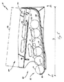
図4及び図5を参照すると、開示される製品陳列及び装填システム10の製品ディスペンサ14は、ディスペンサフレーム70及び製品容器72を含んでいる。製品容器72は、多数のまとまった製品16、例として缶(例えば缶詰食品)、瓶(例えば瓶詰めのソース)またはボトル(例えばボトル入りのソフトドリンク)などを収納している。製品容器72が、例えばディスペンサフレーム70に沿って製品容器72を動かすことによってディスペンサフレーム70上に装填されると、ディスペンサフレーム70は、製品容器72を自動的に開けて、製品容器72からディスペンサフレーム70へ製品16を解放する。
With reference to FIGS. 4 and 5, the
製品容器72をディスペンサフレーム70上に装填する前に製品容器72を手動で開けることを必要とする製品ディスペンサ14の使用も考えられる。
The use of a
製品容器72は、製品16を収納し且つ製品16をディスペンサフレーム70に解放して案内するためにディスペンサフレーム70と有利に相互作用できるのであればどのような容器であってもよい。例えば、製品容器72は、板紙カートンまたは段ボール箱である。任意に、製品容器72の少なくとも1つの主要面は、さまざまなしるし、例えば印刷された文章及び/または図でマークを付けられてもよい。
The
ディスペンサフレーム70は、長手方向長さL(図5)を有し、且つ第1(右)側壁74、第2(左)側壁76、下部支持デッキ78及び上部支持デッキ80を含んでいる。右側壁74は、左側壁76から横方向に間隔をあけられ、且つ左側壁76と略平行である。
The
下部支持デッキ78は、右側壁74と左側壁76との間に横方向に延在し、且つディスペンサフレーム70の前端84に向かって長手方向に延在する前端82と、ディスペンサフレーム70の後端88に向かって長手方向に延在する後端86と、を含んでいる。従って、下部支持デッキ78及び側壁74,76は、ディスペンサフレーム70の下部レベル部90を規定している。
The
下部支持デッキ78は、前端82から後端86へ傾斜しており、このため、下部支持デッキ78の後端86に隣接して置かれた製品16は、重力を受けて下部支持デッキ78の前端82へ転がり落ちる。製品16が下部支持デッキ78の前端82を越えて転がることを防ぐために、停止部92が、下部支持デッキ78の前端82に隣接して設置されている。例えば、停止部92は、下部支持デッキ78に(例えば一体的に)接続され、且つ下部支持デッキ78の前端82において上方への湾曲部を形成している。従って、停止部92は、下部支持デッキ78の前端82において製品16を集め、それにより、下部支持デッキ78の前端82において製品陳列エリア94を規定する。
The
上部支持デッキ80は、右側壁74と左側壁76との間に横方向に延在し、且つディスペンサフレーム70の前端84に向かって長手方向に延在する前端96と、ディスペンサフレーム70の後端88に向かって(ただし、後端88までではない)長手方向に延在する後端98と、を含んでいる。従って、上部支持デッキ80及び側壁74,76は、ディスペンサフレーム70の上部レベル部100を規定している。
The
上部支持デッキ80の後端98とディスペンサフレーム70の後端88との間の間隔102は、開口部104を規定しており、この開口部104は、製品16がディスペンサフレーム70の上部レベル部100から下部レベル部90へ移動することを可能にする落とし口(chute)として機能する。
The spacing 102 between the rear end 98 of the
上部支持デッキ80は、前端96から後端98へ下方に傾けられている。従って、上部支持デッキ80によって支持される製品16は、重力を受けて、上部支持デッキ80の後端98へ転がり落ち、開口部104を通って、ディスペンサフレーム70の下部レベル部90へ、そして最終的に製品陳列エリア94へ転がる。消費者は、製品陳列エリア94から製品16を取ることができる。
The
ディスペンサフレーム70は、開放ツール106をさらに含んでいる。開放ツール106は、製品容器72がディスペンサフレーム70の後端88に向かって上部支持デッキ80に沿って略水平に動かされるときに、製品容器72を切断するために設置されている。製品容器72を切断することによって、開放ツール106は、製品容器72に出口開口部を形成し、この出口開口部は、製品容器72がディスペンサフレーム70上に完全に装填されると、開口部104と整列される。製品容器72に形成される出口開口部により、最初に製品容器72に収納された製品16は、出口開口部を通って製品容器72を出て、ディスペンサフレーム70によって規定される開口部104を通過してディスペンサフレーム70の下部レベル部90へ下方に落下し、そして最終的に製品陳列エリア94へ移動する。
The
製品ディスペンサと、製品容器がディスペンサフレーム上に装填されると製品容器を自動的に開けるための開放ツールと、は2011年4月12日付けで公開された特許文献1でより詳細に説明されている。特許文献1の内容全体は、参照することによって本明細書に組み込まれる。 A product dispenser and an opening tool for automatically opening the product container when the product container is loaded onto the dispenser frame is described in more detail in US Pat. Yes. The entire contents of Patent Document 1 are incorporated herein by reference.
開示される製品陳列及び装填システム10の装填容器18は、少なくとも1つの製品16を受けて支持することができるのであれば、どのような容器であってもよい。従って、消費者は、製品陳列及び装填システム10の製品ディスペンサ14の製品陳列エリア94から1つ以上の製品16を取り、且つ取った製品16を装填容器18内に置くことができる。装填容器18は、製品16が製品陳列及び装填システム10から離れて運ばれるときに(例えば、製品16がレジ及び/または消費者の家に運ばれるときに)製品16を支持し続ける。
The
図6を参照すると、特別な一実施形態では、装填容器18は、内部体積120を規定するために底壁110及び底壁110に接続された側壁112,114,116,118を有するトレイとして構成されている。従って、底壁110及び側壁112,114,116,118は、運ぶ間、装填容器18の内部体積120内に製品16を保持する(図7)。
With reference to FIG. 6, in one particular embodiment, the
任意の一実施では、装填容器18は、装填容器18の側壁112,114,116,118の間に延在する1つ以上の仕切り(図示せず)を含んでいる。いくつかの飲料、例えばワインボトルがケース内に梱包される場合に一般的になされるように、仕切りは、内部体積120を2つ以上の区画(図示せず)に分割する。各区画は、単一の製品16をしっかりと受けるサイズとされ、それにより、運んでいる間の装填容器18内での製品16の動きを(排除するとまではいかなくても)最小化する。
In one optional implementation, the
別の任意の実施では、装填容器18は、輸送ハンドル(図示せず)を含んでいる。輸送ハンドルは、装填された装填容器18を製品陳列及び装填システム10から離れて輸送することを容易にする。
In another optional implementation, the
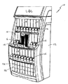
図7を参照すると、棚組立体12には、1つ以上の製品ディスペンサ14及び1つ以上の装填容器18が装填されている。製品ディスペンサ14は、棚組立体12にわたって隣り合う形態で配置されている。装填容器18は、棚組立体12の1つ以上の区画58,60内に積み重ねられて(例えば入れ子にして)設置されている。
Referring to FIG. 7, the
例えば、図2及び図7を参照すると、第1棚42は、第1棚42にわたって隣り合う形態で配置される複数の製品ディスペンサ14を収容するのに十分な横幅W1及び垂直高さH1を有している。9つの製品ディスペンサ14が第1棚42に示されているが、当業者は、第1棚42上の製品ディスペンサ14の数が、いくつかの考えられる要因の中で、第1棚42の横幅W1及び各製品ディスペンサ14の横幅に依存する可能性があることを理解するはずである。
For example, referring to FIGS. 2 and 7, the
第2棚44は、第1区画56内に隣り合う形態で配置される第1の量の製品ディスペンサ14と、第2区画58内に設置される第1の量の装填容器18と、第3区画60内に設置される第2の量の装填容器18と、第4区画62内に隣り合う形態で配置される第2の量の製品ディスペンサ14と、を収容するのに十分な横幅W2及び垂直高さH2を有している。
The
第2棚44の棚の奥行D2は、第2棚部材36上に設置される製品ディスペンサ14の長手方向長さL(図5)よりも著しく大きい。一例として、棚の奥行D2は、製品ディスペンサ14の長手方向長さLの少なくとも1.2倍である。別の例として、棚の奥行D2は、製品ディスペンサ14の長手方向長さLの少なくとも1.5倍である。さらに別の例として、棚の奥行D2は、製品ディスペンサ14の長手方向長さLの少なくとも2倍である。
Depth D 2 of the shelf of the
従って、第2棚44における著しくより大きい棚の奥行D2は、製品ディスペンサ14が第2棚部材36の前端19(図3)上に延在しないことを保証し、それにより、第2棚部材36の前端19において装填面20を規定し、且つ装填面20が妨げられずに装填容器18を支持することができることを保証する。
Therefore, the depth D 2 significantly greater than the shelf in the
第3棚46は、第3棚46にわたって隣り合う形態で配置される複数の製品ディスペンサ14を収容するのに十分な横幅W3及び垂直高さH3を有している。9つの製品ディスペンサ14が第3棚46に示されているが、当業者は、第3棚46上の製品ディスペンサ14の数が、いくつかの考えられる要因の中で、第3棚46の横幅W3及び各製品ディスペンサ14の横幅に依存する可能性があることを理解するはずである。
The
第4棚48は、第4棚48にわたって隣り合う形態で配置される複数の製品ディスペンサ14を収容するのに十分な横幅W4及び垂直高さH4を有している。しかしながら、図1及び図7に示すように、第4棚48は、代わりに、追加の製品容器72を格納するために使用されてもよい。従って、製品陳列及び装填システム10の製品ディスペンサ14が空になったときに、使用者(例えば商品在庫管理係)は、製品ディスペンサ14から空になった製品容器72を取り除いてそれを第4棚48から取った満たされた製品容器72と置き換える。
The
結果として、図7に示すように、消費者は、棚組立体12から装填容器18を選び、且つ棚組立体12の装填面20上に装填容器18を置く。その後、消費者は、棚組立体12上に支持された製品ディスペンサ14の製品陳列エリア94(図4)から製品16を取り、且つ取った製品16を棚組立体12の装填面20上に支持された装填容器18内に装填する。
As a result, as shown in FIG. 7, the consumer selects the
開示される製品陳列及び装填システムのさまざまな態様が示され且つ説明されたが、当業者は、本明細書を読むことで変更を想起するであろう。本出願は、上記変更を含み、且つ特許請求の範囲の権利範囲によってのみ限定される。 While various aspects of the disclosed product display and loading system have been shown and described, those skilled in the art will recognize modifications upon reading this specification. This application includes the above modifications and is limited only by the scope of the claims.
12 棚組立体、14 製品ディスペンサ、18 装填容器、19 前端、20 装填面、21 後端、30 第1側壁、32 第2側壁、34.38,40 第2水平棚部材、36 水平棚部材、50,52,54 垂直棚部材、56,58,60,62 第1区画,第2区画、64 バナー部材、66 しるし、69 底部、70 ディスペンサフレーム、72 製品容器、80 上部支持デッキ、94 製品陳列エリア、106 開放ツール、D2 棚の奥行、E 距離、L 長手方向長さ 12 shelf assembly, 14 product dispenser, 18 loading container, 19 front end, 20 loading surface, 21 rear end, 30 first side wall, 32 second side wall, 34.38, 40 second horizontal shelf member, 36 horizontal shelf member, 50, 52, 54 Vertical shelf member, 56, 58, 60, 62 First compartment, Second compartment, 64 Banner member, 66 Indicator, 69 Bottom, 70 Dispenser frame, 72 Product container, 80 Upper support deck, 94 Product display Area, 106 Opening tool, D 2 Depth of shelf, E distance, L Longitudinal length
Claims (20)
前記水平棚部材上に設置される製品ディスペンサであって、前記前端に隣接する装填面を規定するために前記前端から間隔をあけられている、製品ディスペンサと、
を備えることを特徴とする製品陳列及び装填システム。 A shelf assembly comprising a substantially horizontal shelf member having a front end and a rear end;
A product dispenser installed on the horizontal shelf member, the product dispenser being spaced from the front end to define a loading surface adjacent to the front end;
A product display and loading system comprising:
前記水平棚部材は、前記第1側壁と前記第2側壁との間に横方向に延在していることを特徴とする請求項1に記載の製品陳列及び装填システム。 The shelf assembly includes a first side wall spaced laterally from a second side wall,
The product display and loading system according to claim 1, wherein the horizontal shelf member extends laterally between the first side wall and the second side wall.
前記水平棚部材及び前記垂直棚部材は、第1区画及び第2区画を規定し、前記第1区画は、前記垂直棚部材によって前記第2区画から分離されていることを特徴とする請求項1に記載の製品陳列及び装填システム。 The shelf assembly further includes a substantially vertical shelf member,
The horizontal shelf member and the vertical shelf member define a first section and a second section, and the first section is separated from the second section by the vertical shelf member. The product display and loading system described in 1.
前記水平棚部材は、垂直方向において前記底部から所定距離間隔をあけられていることを特徴とする請求項1に記載の製品陳列及び装填システム。 The shelf assembly includes a bottom,
The product display and loading system according to claim 1, wherein the horizontal shelf member is spaced a predetermined distance from the bottom in the vertical direction.
前記棚の奥行は、前記長手方向長さの少なくとも1.2倍であることを特徴とする請求項1に記載の製品陳列及び装填システム。 The horizontal shelf member has a shelf depth, and the product dispenser has a longitudinal length;
The product display and loading system according to claim 1, wherein a depth of the shelf is at least 1.2 times the longitudinal length.
前記水平棚部材上に設置される複数の製品ディスペンサであって、前記前端に隣接する装填面を規定するために前記前端から間隔をあけられている、製品ディスペンサと、
前記棚組立体上に支持される複数の装填容器と、
を備える製品陳列及び装填システムであって、
前記複数の装填容器の各装填容器は、前記装填容器が前記装填面上に設置されるときに前記前端と前記複数の製品ディスペンサとの間に適合するサイズとされていることを特徴とする製品陳列及び装填システム。 A shelf assembly comprising a substantially horizontal shelf member having a front end and a rear end;
A plurality of product dispensers installed on the horizontal shelf member, wherein the product dispensers are spaced from the front end to define a loading surface adjacent to the front end;
A plurality of loading containers supported on the shelf assembly;
A product display and loading system comprising:
Each loading container of the plurality of loading containers is sized to fit between the front end and the plurality of product dispensers when the loading container is installed on the loading surface. Display and loading system.
前端及び後端を有する略水平棚部材を備える棚組立体を準備するステップと、
製品ディスペンサが、前記前端に隣接する装填面を規定するために前記水平棚部材の前記前端から間隔をあけられるように、前記水平棚部材上に前記製品ディスペンサを設置するステップであって、前記製品ディスペンサが前記製品を支持する、ステップと、
前記装填面上に前記装填容器を設置するステップと、
前記製品を前記製品ディスペンサから前記装填容器へ移すステップと、
を含むことを特徴とする方法。 A method for loading a product into a loading container from a product display, the method comprising:
Providing a shelf assembly comprising a generally horizontal shelf member having a front end and a rear end;
Installing the product dispenser on the horizontal shelf member such that the product dispenser is spaced from the front end of the horizontal shelf member to define a loading surface adjacent to the front end, A dispenser supports the product; and
Installing the loading container on the loading surface;
Transferring the product from the product dispenser to the loading container;
A method comprising the steps of:
Applications Claiming Priority (3)
| Application Number | Priority Date | Filing Date | Title |
|---|---|---|---|
| US13/306,126 | 2011-11-29 | ||
| US13/306,126 US20130134119A1 (en) | 2011-11-29 | 2011-11-29 | Product Display and Loading System |
| PCT/US2012/066578 WO2013081988A1 (en) | 2011-11-29 | 2012-11-27 | Product display and loading system |
Publications (2)
| Publication Number | Publication Date |
|---|---|
| JP2014533591A true JP2014533591A (en) | 2014-12-15 |
| JP2014533591A5 JP2014533591A5 (en) | 2016-01-21 |
Family
ID=47351985
Family Applications (1)
| Application Number | Title | Priority Date | Filing Date |
|---|---|---|---|
| JP2014543606A Pending JP2014533591A (en) | 2011-11-29 | 2012-11-27 | Product display and loading system |
Country Status (12)
| Country | Link |
|---|---|
| US (1) | US20130134119A1 (en) |
| EP (1) | EP2785218A1 (en) |
| JP (1) | JP2014533591A (en) |
| CN (1) | CN104105431A (en) |
| AU (1) | AU2012346202A1 (en) |
| BR (1) | BR112014007586A2 (en) |
| CA (1) | CA2856712A1 (en) |
| MX (1) | MX2014006436A (en) |
| RU (1) | RU2580999C1 (en) |
| TW (1) | TW201332493A (en) |
| WO (1) | WO2013081988A1 (en) |
| ZA (1) | ZA201403816B (en) |
Families Citing this family (13)
| Publication number | Priority date | Publication date | Assignee | Title |
|---|---|---|---|---|
| US9508211B2 (en) | 2010-07-01 | 2016-11-29 | The Coca-Cola Company | Merchandiser |
| US9576419B2 (en) | 2010-07-01 | 2017-02-21 | The Coca-Cola Company | Merchandiser |
| US20120217213A1 (en) * | 2011-02-25 | 2012-08-30 | Laurel Thomas | Product Dispenser and System Configured for Reduced Shelf Height |
| US20130221020A1 (en) * | 2012-02-24 | 2013-08-29 | Matthew E. Zacherle | Product Dispensing System with Staged Container Opening |
| US8955695B2 (en) * | 2013-03-14 | 2015-02-17 | Giraffx Design, LLC | Serpentine dispenser with cartridges |
| WO2014176330A1 (en) * | 2013-04-23 | 2014-10-30 | Minibar Systems | Controlled inventory refrigerated dispensing system |
| US9659426B2 (en) | 2013-08-29 | 2017-05-23 | Giraffx Design, LLC | Dispenser for rolling product and dispenser cartridges |
| CN106413483B (en) * | 2013-12-23 | 2020-06-30 | 可口可乐公司 | Vending machine with product dispensing chute mechanism |
| US10058195B2 (en) * | 2014-08-26 | 2018-08-28 | Menasha Corporation | Can dispenser |
| US9615674B2 (en) * | 2015-03-11 | 2017-04-11 | Trinity, Llc | Can dispenser and merchandiser |
| DE102015115088B3 (en) * | 2015-09-08 | 2016-11-24 | Wanzl Metallwarenfabrik Gmbh | output device |
| CN114269207A (en) * | 2019-06-26 | 2022-04-01 | 奎斯特诊断投资有限责任公司 | System and method for storing and dispensing immunoassays |
| USD980069S1 (en) | 2020-07-14 | 2023-03-07 | Ball Corporation | Metallic dispensing lid |
Citations (5)
| Publication number | Priority date | Publication date | Assignee | Title |
|---|---|---|---|---|
| JPH1014725A (en) * | 1996-06-28 | 1998-01-20 | Hirao Tanimizu | Take-in/take-out rack for canned beverage for showcase |
| JPH11187955A (en) * | 1997-12-26 | 1999-07-13 | Ace Denken:Kk | Article display device and article control method |
| JP2004191048A (en) * | 2004-02-20 | 2004-07-08 | Fukushima Industries Corp | Open showcase |
| JP2009227332A (en) * | 2008-03-19 | 2009-10-08 | E Kankyo Supply:Kk | Beverage fountain unit |
| US7922437B1 (en) * | 2009-11-23 | 2011-04-12 | Meadwestvaco Corporation | Display system, dispensing device and package for use therein |
Family Cites Families (30)
| Publication number | Priority date | Publication date | Assignee | Title |
|---|---|---|---|---|
| ES177246Y (en) * | 1968-10-11 | 1973-11-16 | J H. Laurent | SELF-SERVICE FOOD DISTRIBUTOR APPARATUS. |
| US3868021A (en) * | 1973-10-09 | 1975-02-25 | Wilhelm Heinrich | Separator panel holder for display shelves |
| US4136783A (en) * | 1977-02-28 | 1979-01-30 | Masashi Karashima | Showcase equipment |
| CA1113536A (en) * | 1980-05-12 | 1981-12-01 | Romanino Vona | Bulk food display bin |
| US4488652A (en) * | 1983-03-14 | 1984-12-18 | The Mead Corporation | Merchandising display connector means |
| JPS6392984U (en) * | 1986-12-05 | 1988-06-15 | ||
| US5439123A (en) * | 1993-08-03 | 1995-08-08 | Harbor Industries, Inc. | Display system |
| FR2709053B1 (en) * | 1993-08-16 | 1995-10-27 | Bernardin Didier | Display back wall and display integrating said wall. |
| US5529192A (en) * | 1994-03-31 | 1996-06-25 | Conen; Ella B. | Display fixture system |
| US5573124A (en) * | 1994-11-08 | 1996-11-12 | Frost; Michael J. | High density showroom storage and display rack |
| US5871108A (en) * | 1996-11-29 | 1999-02-16 | The Coca-Cola Company | Rear loading merchandise shelving arrangement |
| US5732834A (en) * | 1997-02-18 | 1998-03-31 | Felbro, Inc. | Front end merchandiser with check-out lane blocker |
| US6105796A (en) * | 1998-09-03 | 2000-08-22 | Eveready Battery Company, Inc. | Merchandising display lane blocker |
| US6427857B1 (en) * | 1999-03-26 | 2002-08-06 | The Mead Corporation | Expandable display apparatus and methods |
| US6520355B1 (en) * | 1999-03-26 | 2003-02-18 | L&P Property Management Company | Adjustable shelving/display system |
| US6659295B1 (en) * | 1999-03-26 | 2003-12-09 | L&P Property Management Company | Adjustable shelving/display system |
| US6267258B1 (en) * | 1999-05-07 | 2001-07-31 | Gilmour, Inc. | Gravity feed pull out shelf with rear storage area and associated method for displaying and storing a product |
| US6494328B1 (en) * | 2000-08-23 | 2002-12-17 | L&P Property Management Company | Modular gravity feed dispenser unit |
| WO2002041731A2 (en) * | 2000-11-21 | 2002-05-30 | L & P Property Management Company | Product display and dispensing system |
| US6405880B1 (en) * | 2001-07-02 | 2002-06-18 | Rtc Industries, Inc. | Rack merchandising system |
| US7131543B2 (en) * | 2003-01-22 | 2006-11-07 | New Dimensions Research Corporation | Display device |
| US7661545B2 (en) * | 2004-02-03 | 2010-02-16 | Rtc Industries, Inc. | Product securement and management system |
| US20060016774A1 (en) * | 2004-06-25 | 2006-01-26 | L&P Property Management Company | Gondola conversion apparatus and method |
| CA2568612C (en) * | 2006-10-11 | 2012-07-24 | Harbor Industries, Inc. | Display assembly with adjustable shelves |
| US7950536B2 (en) * | 2007-04-11 | 2011-05-31 | Target Brands, Inc. | System for displaying merchandise in front of backer material |
| CA126910S (en) * | 2008-01-31 | 2009-11-03 | Eveready Battery Inc | Merchandiser rack |
| US20100108625A1 (en) * | 2008-11-03 | 2010-05-06 | Meers Ryan C | Merchandising system |
| WO2011030320A1 (en) * | 2009-09-14 | 2011-03-17 | Eureka Diy Solutions (Proprietary) Limited | Modular display and dispensing arrangement |
| US20110062096A1 (en) * | 2009-09-15 | 2011-03-17 | Sparkowski Robert P | Sliding product reducer assembly |
| US9090390B2 (en) * | 2010-09-27 | 2015-07-28 | Meadwestvaco Corporation | Product dispensing system |
-
2011
- 2011-11-29 US US13/306,126 patent/US20130134119A1/en not_active Abandoned
-
2012
- 2012-11-27 WO PCT/US2012/066578 patent/WO2013081988A1/en active Application Filing
- 2012-11-27 CA CA2856712A patent/CA2856712A1/en not_active Abandoned
- 2012-11-27 BR BR112014007586A patent/BR112014007586A2/en not_active IP Right Cessation
- 2012-11-27 EP EP12799416.8A patent/EP2785218A1/en not_active Withdrawn
- 2012-11-27 AU AU2012346202A patent/AU2012346202A1/en not_active Abandoned
- 2012-11-27 CN CN201280058727.4A patent/CN104105431A/en active Pending
- 2012-11-27 MX MX2014006436A patent/MX2014006436A/en unknown
- 2012-11-27 RU RU2014126071/12A patent/RU2580999C1/en not_active IP Right Cessation
- 2012-11-27 JP JP2014543606A patent/JP2014533591A/en active Pending
- 2012-11-28 TW TW101144460A patent/TW201332493A/en unknown
-
2014
- 2014-05-23 ZA ZA2014/03816A patent/ZA201403816B/en unknown
Patent Citations (5)
| Publication number | Priority date | Publication date | Assignee | Title |
|---|---|---|---|---|
| JPH1014725A (en) * | 1996-06-28 | 1998-01-20 | Hirao Tanimizu | Take-in/take-out rack for canned beverage for showcase |
| JPH11187955A (en) * | 1997-12-26 | 1999-07-13 | Ace Denken:Kk | Article display device and article control method |
| JP2004191048A (en) * | 2004-02-20 | 2004-07-08 | Fukushima Industries Corp | Open showcase |
| JP2009227332A (en) * | 2008-03-19 | 2009-10-08 | E Kankyo Supply:Kk | Beverage fountain unit |
| US7922437B1 (en) * | 2009-11-23 | 2011-04-12 | Meadwestvaco Corporation | Display system, dispensing device and package for use therein |
Also Published As
| Publication number | Publication date |
|---|---|
| US20130134119A1 (en) | 2013-05-30 |
| ZA201403816B (en) | 2015-10-28 |
| WO2013081988A1 (en) | 2013-06-06 |
| BR112014007586A2 (en) | 2017-04-04 |
| TW201332493A (en) | 2013-08-16 |
| CN104105431A (en) | 2014-10-15 |
| AU2012346202A1 (en) | 2014-04-17 |
| RU2580999C1 (en) | 2016-04-10 |
| EP2785218A1 (en) | 2014-10-08 |
| CA2856712A1 (en) | 2013-06-06 |
| MX2014006436A (en) | 2014-07-11 |
Similar Documents
| Publication | Publication Date | Title |
|---|---|---|
| JP2014533591A (en) | Product display and loading system | |
| US8302809B1 (en) | Product dispensing system with increased product-to-dispenser contact | |
| US20060027639A1 (en) | Dispensing caddy | |
| US20110121011A1 (en) | Product Dispensing System With Anti-Theft Engagement | |
| KR20130103749A (en) | Product dispensing system | |
| KR20130139922A (en) | Product dispensing container, system and method with priming area | |
| US20130020341A1 (en) | Product Dispensing System with Multiple Dispensing Decks | |
| US20120285977A1 (en) | Product Dispensing System | |
| US8985346B2 (en) | Multi-deck product dispensing system with rear guide | |
| US20120217213A1 (en) | Product Dispenser and System Configured for Reduced Shelf Height | |
| KR20130044209A (en) | Devices for dispensing and displaying products and package assemblies for use with the same | |
| US20130264351A1 (en) | Product Dispensing System | |
| WO2011030320A1 (en) | Modular display and dispensing arrangement | |
| US9096345B2 (en) | Product dispensing system with reinforced weakening features | |
| US9731860B2 (en) | Tray with integrated support structures | |
| US8550261B2 (en) | Product dispensing system with flexing container | |
| US20140076922A1 (en) | Product Dispensing System with Increased Container and Dispenser Openings | |
| US20140001200A1 (en) | Product Dispenser and Shelf Assembly | |
| US20070199852A1 (en) | Product and method for dispensing and packaging items having complementary components | |
| US9591933B2 (en) | Display tray | |
| EA010195B1 (en) | Stacking feeder of increased capacity and product item dispensers for use thereof | |
| US20130240553A1 (en) | Product Dispenser and System with Pivoting Container Support Deck |
Legal Events
| Date | Code | Title | Description |
|---|---|---|---|
| A521 | Request for written amendment filed |
Free format text: JAPANESE INTERMEDIATE CODE: A523 Effective date: 20151125 |
|
| A621 | Written request for application examination |
Free format text: JAPANESE INTERMEDIATE CODE: A621 Effective date: 20151125 |
|
| A977 | Report on retrieval |
Free format text: JAPANESE INTERMEDIATE CODE: A971007 Effective date: 20161109 |
|
| A131 | Notification of reasons for refusal |
Free format text: JAPANESE INTERMEDIATE CODE: A131 Effective date: 20161121 |
|
| A02 | Decision of refusal |
Free format text: JAPANESE INTERMEDIATE CODE: A02 Effective date: 20170619 |