JP2014532824A - Hydrogen generator with diaphragm pump - Google Patents
Hydrogen generator with diaphragm pump Download PDFInfo
- Publication number
- JP2014532824A JP2014532824A JP2014537156A JP2014537156A JP2014532824A JP 2014532824 A JP2014532824 A JP 2014532824A JP 2014537156 A JP2014537156 A JP 2014537156A JP 2014537156 A JP2014537156 A JP 2014537156A JP 2014532824 A JP2014532824 A JP 2014532824A
- Authority
- JP
- Japan
- Prior art keywords
- pump
- hydrogen generator
- liquid
- diaphragm
- generator according
- Prior art date
- Legal status (The legal status is an assumption and is not a legal conclusion. Google has not performed a legal analysis and makes no representation as to the accuracy of the status listed.)
- Ceased
Links
Images


Classifications
-
- H—ELECTRICITY
- H01—ELECTRIC ELEMENTS
- H01M—PROCESSES OR MEANS, e.g. BATTERIES, FOR THE DIRECT CONVERSION OF CHEMICAL ENERGY INTO ELECTRICAL ENERGY
- H01M8/00—Fuel cells; Manufacture thereof
- H01M8/06—Combination of fuel cells with means for production of reactants or for treatment of residues
- H01M8/0606—Combination of fuel cells with means for production of reactants or for treatment of residues with means for production of gaseous reactants
-
- C—CHEMISTRY; METALLURGY
- C01—INORGANIC CHEMISTRY
- C01B—NON-METALLIC ELEMENTS; COMPOUNDS THEREOF; METALLOIDS OR COMPOUNDS THEREOF NOT COVERED BY SUBCLASS C01C
- C01B3/00—Hydrogen; Gaseous mixtures containing hydrogen; Separation of hydrogen from mixtures containing it; Purification of hydrogen
- C01B3/02—Production of hydrogen or of gaseous mixtures containing a substantial proportion of hydrogen
- C01B3/06—Production of hydrogen or of gaseous mixtures containing a substantial proportion of hydrogen by reaction of inorganic compounds containing electro-positively bound hydrogen, e.g. water, acids, bases, ammonia, with inorganic reducing agents
- C01B3/065—Production of hydrogen or of gaseous mixtures containing a substantial proportion of hydrogen by reaction of inorganic compounds containing electro-positively bound hydrogen, e.g. water, acids, bases, ammonia, with inorganic reducing agents from a hydride
-
- H—ELECTRICITY
- H01—ELECTRIC ELEMENTS
- H01M—PROCESSES OR MEANS, e.g. BATTERIES, FOR THE DIRECT CONVERSION OF CHEMICAL ENERGY INTO ELECTRICAL ENERGY
- H01M8/00—Fuel cells; Manufacture thereof
- H01M8/06—Combination of fuel cells with means for production of reactants or for treatment of residues
- H01M8/0606—Combination of fuel cells with means for production of reactants or for treatment of residues with means for production of gaseous reactants
- H01M8/065—Combination of fuel cells with means for production of reactants or for treatment of residues with means for production of gaseous reactants by dissolution of metals or alloys; by dehydriding metallic substances
-
- Y—GENERAL TAGGING OF NEW TECHNOLOGICAL DEVELOPMENTS; GENERAL TAGGING OF CROSS-SECTIONAL TECHNOLOGIES SPANNING OVER SEVERAL SECTIONS OF THE IPC; TECHNICAL SUBJECTS COVERED BY FORMER USPC CROSS-REFERENCE ART COLLECTIONS [XRACs] AND DIGESTS
- Y02—TECHNOLOGIES OR APPLICATIONS FOR MITIGATION OR ADAPTATION AGAINST CLIMATE CHANGE
- Y02E—REDUCTION OF GREENHOUSE GAS [GHG] EMISSIONS, RELATED TO ENERGY GENERATION, TRANSMISSION OR DISTRIBUTION
- Y02E60/00—Enabling technologies; Technologies with a potential or indirect contribution to GHG emissions mitigation
- Y02E60/30—Hydrogen technology
- Y02E60/36—Hydrogen production from non-carbon containing sources, e.g. by water electrolysis
-
- Y—GENERAL TAGGING OF NEW TECHNOLOGICAL DEVELOPMENTS; GENERAL TAGGING OF CROSS-SECTIONAL TECHNOLOGIES SPANNING OVER SEVERAL SECTIONS OF THE IPC; TECHNICAL SUBJECTS COVERED BY FORMER USPC CROSS-REFERENCE ART COLLECTIONS [XRACs] AND DIGESTS
- Y02—TECHNOLOGIES OR APPLICATIONS FOR MITIGATION OR ADAPTATION AGAINST CLIMATE CHANGE
- Y02E—REDUCTION OF GREENHOUSE GAS [GHG] EMISSIONS, RELATED TO ENERGY GENERATION, TRANSMISSION OR DISTRIBUTION
- Y02E60/00—Enabling technologies; Technologies with a potential or indirect contribution to GHG emissions mitigation
- Y02E60/30—Hydrogen technology
- Y02E60/50—Fuel cells
Landscapes
- Chemical & Material Sciences (AREA)
- Engineering & Computer Science (AREA)
- Chemical Kinetics & Catalysis (AREA)
- Life Sciences & Earth Sciences (AREA)
- Organic Chemistry (AREA)
- Manufacturing & Machinery (AREA)
- Sustainable Development (AREA)
- Sustainable Energy (AREA)
- Electrochemistry (AREA)
- General Chemical & Material Sciences (AREA)
- General Health & Medical Sciences (AREA)
- Combustion & Propulsion (AREA)
- Inorganic Chemistry (AREA)
- Health & Medical Sciences (AREA)
- Fuel Cell (AREA)
- Reciprocating Pumps (AREA)
Abstract
本発明は、液体をリザーバから反応エリアに圧送するためのポンプであって、液体は、水素ガスを産生するように反応する、ポンプと、水素発生器および燃料電池スタックを含む、燃料電池システムとを含む、水素発生器である。ポンプは、カム作動式プッシュロッドによって開放される機械作動式液体入口および出口弁を伴う、ダイヤフラムポンプであって、プッシュロッドは、ダイヤフラムによって、ポンプを通る液体流路から隔離される。液体リザーバと反応エリアとの間の液体流路内の全ての弁は、機械作動式弁である。The present invention is a pump for pumping liquid from a reservoir to a reaction area, wherein the liquid reacts to produce hydrogen gas, a fuel cell system including a hydrogen generator and a fuel cell stack. It is a hydrogen generator containing. The pump is a diaphragm pump with a mechanically actuated liquid inlet and outlet valve that is opened by a cam actuated push rod, the push rod being isolated from the liquid flow path through the pump by the diaphragm. All valves in the liquid flow path between the liquid reservoir and the reaction area are mechanically actuated valves.
Description
本発明は、液体反応物質を圧送するためのポンプを伴う、水素発生器と、水素発生器を含む、燃料電池システムとに関する。 The present invention relates to a hydrogen generator with a pump for pumping a liquid reactant and a fuel cell system including the hydrogen generator.
ポータブル電子デバイスのための電源としての燃料電池バッテリにおける関心は、高まりつつある。燃料電池は、正および負電極のための活性材料として、電池外からの材料を使用する、電気化学電池である。燃料電池は、電気を発生させるために使用される活性材料の全てを含有する必要がないため、燃料電池は、他のタイプのバッテリと比較して、産生される電気エネルギーの量に対して、小容積で作製されることができる。 Interest in fuel cell batteries as a power source for portable electronic devices is growing. A fuel cell is an electrochemical cell that uses materials from outside the cell as the active material for the positive and negative electrodes. Because fuel cells do not need to contain all of the active material used to generate electricity, fuel cells are compared to the amount of electrical energy produced compared to other types of batteries. Can be made in small volumes.
いくつかのタイプの燃料電池が存在し、それらは、種々の方法で分類され得る。例えば、燃料電池は、使用される電解質のタイプに従って、典型的には、5つのタイプ:プロトン交換膜燃料電池(PEMFC)、アルカリ燃料電池(AFC)、リン酸燃料電池(PAFC)、固体酸化物燃料電池(SOFC)、および溶融炭酸塩燃料電池(MCFC)のうちの1つにカテゴリ化されることができる。これらのタイプの燃料電池はそれぞれ、水素および酸素を使用する。水素は、負電極において酸化され、酸素は、正電極において還元される。イオンは、電気的に非伝導性のイオン浸透性セパレータを通過し、電子は、外部回路を通過して、電流を提供する。 There are several types of fuel cells, which can be classified in various ways. For example, fuel cells typically have five types, depending on the type of electrolyte used: proton exchange membrane fuel cell (PEMFC), alkaline fuel cell (AFC), phosphoric acid fuel cell (PAFC), solid oxide It can be categorized into one of a fuel cell (SOFC) and a molten carbonate fuel cell (MCFC). Each of these types of fuel cells uses hydrogen and oxygen. Hydrogen is oxidized at the negative electrode and oxygen is reduced at the positive electrode. Ions pass through an electrically non-conductive ion permeable separator and electrons pass through an external circuit to provide a current.
いくつかのタイプの水素燃料電池では、水素は、燃料電池の負電極側に供給される水素含有燃料から形成される。他のタイプの水素燃料電池では、水素ガスは、燃料電池外の源から燃料電池に供給される。 In some types of hydrogen fuel cells, hydrogen is formed from a hydrogen-containing fuel that is supplied to the negative electrode side of the fuel cell. In other types of hydrogen fuel cells, hydrogen gas is supplied to the fuel cell from a source outside the fuel cell.
燃料電池システムは、1つ以上の燃料電池(燃料電池スタック)と、ガスタンクまたはガス発生器等のガス源とを含む、燃料電池バッテリを含むことができる。ガスを燃料電池に供給する、ガス発生器は、燃料電池システムの一体部分であることができる、または燃料電池システムに可撤性に結合されることができる。可撤性ガス発生器は、反応物質を産生するガスが、消費されると、別のものと交換されることができる。可撤性ガス発生器は、使い捨て(1回限りの使用のために意図される)または詰め替え可能(複数回の使用のために意図される)であって、消費された反応物質材料を補充することができる。 The fuel cell system can include a fuel cell battery that includes one or more fuel cells (fuel cell stack) and a gas source, such as a gas tank or a gas generator. The gas generator that supplies gas to the fuel cell can be an integral part of the fuel cell system or can be removably coupled to the fuel cell system. The removable gas generator can be replaced with another once the gas producing the reactant is consumed. The removable gas generator is disposable (intended for one-time use) or refillable (intended for multiple use) and replenishes spent reactant material be able to.
可撤性ガス発生器は、燃料電池システムに容易に結合され、結合時にガス漏出を伴うことなく、ガス発生器から燃料電池システムの残部へのガス流路を生成することが望ましく、また、ガス発生器は、燃料電池システムの残部に結合されていないときも、ガス漏出がないことが望ましい。ガス発生器と燃料電池システムの残部との間の結合は、1つ以上の弁を含むことができる。弁は、手動で開放および閉鎖されることができる、弁動作は、制御システムによって制御されることができる、あるいは弁は、構成要素の結合を行なうまたは分離することによって動作される、アクチュエータによって、開放および閉鎖されることができる。後者の方法は、迅速な結合分断において使用されることができ、例えば、弁は、ガス発生器がシステムの残部に結合されると、開放され、ガス発生器が分断されると、閉鎖される。 The removable gas generator is easily coupled to the fuel cell system and desirably produces a gas flow path from the gas generator to the remainder of the fuel cell system without gas leakage when coupled. Desirably, the generator is free of gas leakage even when it is not coupled to the remainder of the fuel cell system. The coupling between the gas generator and the remainder of the fuel cell system can include one or more valves. The valve can be manually opened and closed, the valve operation can be controlled by a control system, or the valve can be operated by making or separating components, by an actuator, Can be opened and closed. The latter method can be used in rapid disconnection, for example, the valve is opened when the gas generator is connected to the rest of the system and closed when the gas generator is disconnected. .
ガス発生器は、種々のタイプの反応物質を使用して、ガスを産生することができる。あるタイプの水素発生器では、少なくとも1つの反応物質が、リザーバ内に液体として貯蔵され、液体は、リザーバから反応チャンバに移送され、そこで、所望のガスを産生するように反応する。重力流、液体への圧力の印加、毛細管作用による液体の吸い上げ、および機械的ポンプを用いた圧送を含む、種々の手段が、液体を移送するために使用されている。各方法は、利点および不利点を有する。 Gas generators can use various types of reactants to produce gas. In one type of hydrogen generator, at least one reactant is stored as a liquid in a reservoir, and the liquid is transferred from the reservoir to the reaction chamber where it reacts to produce the desired gas. Various means have been used to transfer liquids, including gravity flow, application of pressure to the liquid, pumping of liquid by capillary action, and pumping using a mechanical pump. Each method has advantages and disadvantages.
液体の圧送は、圧送が開始および停止されることができ、したがって、ガスが必要ベースで産生されるため、有利であり得る。ポンプもまた、制御された割合で液体を提供することができる。ガス発生器と併用されるポンプの選択の際、ポンプ材料および構成要素の圧送される液体との適合性、使用される環境に耐えるポンプの能力(例えば、温度および圧力)、ポンプのサイズ、圧送割合、割合制御(正確度および精度)、ポンプを動作させるために要求される動力の量およびタイプ、ガス発生器またはシステム内へのポンプの統合、ポンプのガスの産生を制御する方法との適合性、ポンプの信頼性、ならびに動作の間、ポンプによって産生される熱および雑音の量等、多くの要因が、考慮され得る。 Liquid pumping can be advantageous because pumping can be started and stopped, and thus gas is produced on a necessary basis. The pump can also provide liquid at a controlled rate. When selecting a pump for use with a gas generator, the compatibility of the pump material and components with the pumped liquid, the pump's ability to withstand the environment used (eg temperature and pressure), pump size, pumping Rate, rate control (accuracy and accuracy), amount and type of power required to operate the pump, integration of the pump into the gas generator or system, and compatibility with methods to control pump gas production Many factors can be considered, such as performance, pump reliability, and the amount of heat and noise produced by the pump during operation.
前述に照らして、本発明の目的は、ガス発生器内の液体反応物質を圧送するために好適なポンプと、ポンプを含む、燃料電池システム、特に、通信機器、ポータブルコンピュータ、およびビデオゲーム等のポータブル消費者電子デバイスに給電するために使用され得る燃料電池システムとを提供することである。 In light of the foregoing, it is an object of the present invention to provide a pump suitable for pumping a liquid reactant in a gas generator and a fuel cell system including the pump, particularly communication equipment, portable computers, video games, and the like. A fuel cell system that can be used to power portable consumer electronic devices.
前述の目的は、以下に説明されるポンプ、ポンプを含む、水素発生器、および水素発生器を含む、燃料電池システムによって、充足され、先行技術の前述の不利点も、それらによって、克服される。 The foregoing objects are met by a fuel cell system including a pump, including a pump, a hydrogen generator, and a hydrogen generator as described below, and the aforementioned disadvantages of the prior art are overcome thereby. .
故に、本発明の一側面は、筐体と、液体反応物質を含有し、筐体内に配置される、液体リザーバと、筐体内に配置される、反応エリアと、液体反応物質を液体リザーバから、液体流路を通して、反応エリアに圧送するように構成される、ポンプとを含み、液体は、反応エリア内で反応し、水素ガスを放出する、水素発生器である。ポンプは、ダイヤフラムポンプであって、ある容積を有する、ポンプチャンバと、ポンプチャンバの一部を画定する、第1のダイヤフラムと、入口弁がその中に配置される、ポンプチャンバへの液体入口経路であって、入口弁は、閉鎖位置において、第2のダイヤフラムに対して付勢される、液体入口経路と、出口弁がその中に配置される、ポンプチャンバからの液体出口経路であって、出口弁は、閉鎖位置において、第3のダイヤフラムに対して付勢される、液体出口経路と、回転可能シャフトを伴う、モータと、全て、回転可能シャフト上に配置される、第1のカム、第2のカムおよび第3のカムと、第1のカムと接触し、第1のカムと協働して、第1のダイヤフラムを可逆的に変位させ、ポンプチャンバ容積を減少させるように構成される、第1のプッシュロッドと、第2のカムと接触し、第2のカムと協働して、第2のダイヤフラムを可逆的に変位させ、入口弁を開放させるように構成される、第2のプッシュロッドと、第3のカムと接触し、第3のカムと協働し、第3のダイヤフラムを可逆的に変位させ、出口弁を開放させるように構成される、第3のプッシュロッドとを含む。液体リザーバと反応エリアとの間の液体流路内の全ての弁は、機械作動式弁である。 Thus, one aspect of the present invention provides a housing, a liquid reservoir containing the liquid reactant, disposed in the housing, a reaction area disposed in the housing, and the liquid reactant from the liquid reservoir. A liquid configured to pump through the liquid flow path to the reaction area, the liquid reacting in the reaction area and releasing hydrogen gas. The pump is a diaphragm pump having a volume, a pump chamber, a first diaphragm defining a portion of the pump chamber, and a liquid inlet path to the pump chamber in which an inlet valve is disposed An inlet valve is a liquid inlet path that is biased against the second diaphragm in the closed position and a liquid outlet path from the pump chamber in which the outlet valve is disposed; The outlet valve is biased against the third diaphragm in the closed position, a liquid outlet path, a motor with a rotatable shaft, and a first cam, all disposed on the rotatable shaft; The second cam and the third cam are configured to contact the first cam and cooperate with the first cam to reversibly displace the first diaphragm and reduce the pump chamber volume. A first push rod in contact with the second cam and configured to reversibly displace the second diaphragm and open the inlet valve in cooperation with the second cam, A third push rod configured to contact the second push rod and the third cam, cooperate with the third cam, reversibly displace the third diaphragm and open the outlet valve Including. All valves in the liquid flow path between the liquid reservoir and the reaction area are mechanically actuated valves.
実施形態は、以下の特徴のうちの1つ以上を含むことができる。
● 第1、第2、および第3のダイヤフラムは、単一ダイヤフラムシートの別個のエリアであって、ダイヤフラムシートは、架橋フッ素ポリマーを含むことができる。
● 入口および出口弁は、それぞれ、入口弁バネおよび出口弁バネによって、第2および第3のダイヤフラムに対して付勢される。
● ポンプは、ポンプ本体を含み、その中に、ポンプチャンバ、液体入口経路、および液体出口経路が、配置される。
● ポンプ本体内の空洞および第1のダイヤフラムによって画定される、最大ポンプチャンバ容積は、0.01cm3〜1cm3である。
● ポンプは、最大100サイクル/分で動作するように構成される。
● モータは、電気モータである。
● ポンプは、水素発生器筐体内に配置される。
● ポンプは、水素発生器筐体外に配置される。
● 液体は、水を含む、液体は、酸を含むことができる、液体は、塩基を含むことができる、または液体は、化学水素化物を含有することができる。
● 水素発生器は、反応エリア内に配置される、固体反応物質を有する。
● 水素発生器は、反応エリア内に配置される、触媒を有する。
● ポンプは、所定のポンプ位置を感知するためのセンサを含む。
Embodiments can include one or more of the following features.
The first, second, and third diaphragms are separate areas of a single diaphragm sheet, and the diaphragm sheet can include a cross-linked fluoropolymer.
The inlet and outlet valves are biased against the second and third diaphragms by the inlet valve spring and the outlet valve spring, respectively.
● The pump includes a pump body in which a pump chamber, a liquid inlet path, and a liquid outlet path are disposed.
● defined by cavity and the first diaphragm in the pump body, the maximum pump chamber volume is 0.01 cm 3 1 cm 3.
● The pump is configured to operate at a maximum of 100 cycles / minute.
● The motor is an electric motor.
● The pump is placed in the hydrogen generator housing.
● The pump is located outside the hydrogen generator housing.
• The liquid can contain water, the liquid can contain an acid, the liquid can contain a base, or the liquid can contain a chemical hydride.
● The hydrogen generator has a solid reactant that is placed in the reaction area.
● The hydrogen generator has a catalyst placed in the reaction area.
● The pump includes a sensor for sensing a predetermined pump position.
本発明の第2の側面は、ポンプおよび燃料電池スタックを含む、燃料電池システムである。ある実施形態では、ポンプの動作は、燃料電池スタックのために要求される水素放出割合に基づいて、制御されることができる。 The second aspect of the present invention is a fuel cell system including a pump and a fuel cell stack. In some embodiments, the operation of the pump can be controlled based on the hydrogen release rate required for the fuel cell stack.
本発明のこれらおよび他の特徴、利点、ならびに目的は、以下の明細書、請求項、および添付の図面を参照することによって、当業者によってさらに理解および認識されるであろう。 These and other features, advantages, and objects of the present invention will be further understood and appreciated by those skilled in the art by reference to the following specification, claims, and appended drawings.
本明細書で別様に規定されない限り、開示される特性および範囲は全て、室温(20〜25℃)で判定される。 Unless otherwise specified herein, all disclosed properties and ranges are determined at room temperature (20-25 ° C.).
「上部」、「下部」、「上方」、「下方」、「上側」、「下側」、「上」、「下」、「正面」、「背面」、「左」、「右」、およびその変形例等の空間的相対用語の使用は、別様に記載されない限り、図面に図示されるように、別の要素または特徴に対するある要素または特徴の関係を説明するための説明の容易さのために意図されるものである。 “Upper”, “Lower”, “Upper”, “Lower”, “Upper”, “Lower”, “Upper”, “Lower”, “Front”, “Back”, “Left”, “Right”, and The use of spatial relative terms such as variations thereof, unless otherwise stated, facilitates explanation to explain the relationship of one element or feature to another element or feature, as illustrated in the drawings. Is intended.
市販のポンプは、ガス発生器および燃料電池システムにおける使用のための所望の特徴が欠如していることが分かっている。以下に説明されるポンプは、選択される具体的材料に応じて、水、酸、および塩基水溶液、アルコール等の水素含有炭化水素、およびヒドラジン等の非水性液体を含む、種々のタイプのガス発生器のための種々の液体反応物質と適合性がある。ポンプは、広範囲にわたる割合で液体を圧送するように定寸されることができ、容易に始動および停止されることができ、かつポンプモータが旋回する方向に基づいて、いずれかの方向に液体を圧送することができる。ポンプは、選択される具体的材料に応じた温度に耐えることができる。ポンプは、静音で動作し、したがって、燃料電池システムによって給電されるデバイスのユーザの妨害にはならないであろう。ポンプはまた、単純設計および低コストを有する。 Commercially available pumps have been found to lack the desired features for use in gas generators and fuel cell systems. The pumps described below can generate various types of gas generation, including water, acid and base aqueous solutions, hydrogen-containing hydrocarbons such as alcohols, and non-aqueous liquids such as hydrazine, depending on the specific materials selected. Compatible with various liquid reactants for the vessel. The pump can be sized to pump liquid at a wide range of rates, can be easily started and stopped, and pumps liquid in either direction based on the direction in which the pump motor turns. Can be pumped. The pump can withstand temperatures depending on the specific material selected. The pump operates silently and therefore will not interfere with the user of the device powered by the fuel cell system. The pump also has a simple design and low cost.
本発明によるポンプは、機械作動式弁を伴う、モータ駆動式ダイヤフラムポンプである。機械作動式弁(圧力に応答して、開放および/または閉鎖しない弁)は、確動的に閉鎖される(例えば、バネによって)ため、有利であって、したがって、弁が閉鎖されると、内部または外部過圧によってさえ、いずれの方向にも液体の自由な流動は存在しない。実際、外部過圧(例えば、ガス発生器から)は、弁をさらにきつく閉鎖する傾向となるであろう。圧力応答逆止弁は、使用されないため、ポンプは、始動時に、より自吸可能となる。ポンプは、機械作動式弁を伴う、ダイヤフラムポンプであるため、管類がより急速に劣化し得る、蠕動ポンプにおけるように、ゴム管類を緊締し、液体の自由流動を防止する必要はない。機械作動式弁を伴う、ダイヤフラムポンプもまた、静音で動作する。 The pump according to the invention is a motor driven diaphragm pump with a mechanically actuated valve. Mechanically actuated valves (valves that do not open and / or close in response to pressure) are advantageous because they are positively closed (e.g., by a spring), so when the valve is closed, There is no free flow of liquid in either direction, even with internal or external overpressure. In fact, external overpressure (eg, from a gas generator) will tend to close the valve more tightly. Since the pressure responsive check valve is not used, the pump can be more self-priming when starting. Since the pump is a diaphragm pump with mechanically actuated valves, it is not necessary to tighten the rubber tubing and prevent free flow of liquid as in peristaltic pumps where the tubing can degrade more rapidly. Diaphragm pumps with mechanically actuated valves also operate silently.
ポンプチャンバは、ポンプが、所望の最大割合で液体を提供することを可能にするように定寸される。ポンプダイヤフラムおよび弁は、カム駆動式プッシュロッドによって変位される。弁を動作させるプッシュロッドは、ダイヤフラムをシールすることによって、弁から隔離され、したがって、プッシュロッドは、圧送される液体に接触せず、それによって、それらを液体から保護し、ポンプの有用寿命を延長させ、より多くの代替および/またはより安価な材料を実行可能にする。ポータブル消費者電子機器を給電する、燃料電池システムにおいて使用されるポンプの場合、1〜5cm3の液体/分を圧送可能なポンプが、所望され得る。60サイクル/分で動作するポンプの場合、これは、容積0.015〜0.085cm3を伴うポンプチャンバを要求するであろう。より大きなポンプを伴う燃料電池システムは、ユーザによって携行されるように意図される機器には、大き過ぎる場合がある。より小さいポンプを要求する燃料電池システムは、電子デバイスならびにポンプモータの両方を給電可能な燃料電池スタックを有していない場合がある。いくつかの実施形態では、ポンプは、最大動作速度約100サイクル/分を有することができる。 The pump chamber is sized to allow the pump to provide liquid at the desired maximum rate. The pump diaphragm and valve are displaced by a cam driven push rod. The push rod that operates the valve is isolated from the valve by sealing the diaphragm, so the push rod does not come into contact with the pumped liquid, thereby protecting them from the liquid and increasing the useful life of the pump. Extend and allow more alternative and / or less expensive materials to work. For pumps used in fuel cell systems that power portable consumer electronics, a pump capable of pumping 1-5 cm 3 of liquid / min may be desired. For a pump operating at 60 cycles / min, this would require a pump chamber with a volume of 0.015-0.085 cm 3 . A fuel cell system with a larger pump may be too large for equipment intended to be carried by the user. Fuel cell systems that require smaller pumps may not have a fuel cell stack that can power both the electronic device as well as the pump motor. In some embodiments, the pump can have a maximum operating speed of about 100 cycles / minute.
モータは、交流または直流のいずれかで動作する、電気モータであることができる。モータは、燃料電池システム内の燃料電池スタックまたは燃料電池システム内の別の電気電源、燃料電池システムによって給電される電子デバイス、あるいは燃料電池システムおよび電子デバイスの外部の電源によって給電されることができる。所望に応じて、モータおよびポンプは、可逆式であることができる。これは、液体の流動と、例えば、結果として生じるガスの発生とをより迅速に停止させるために有利であり得る。 The motor can be an electric motor that operates on either alternating current or direct current. The motor can be powered by a fuel cell stack within the fuel cell system or another electrical power source within the fuel cell system, an electronic device powered by the fuel cell system, or a power source external to the fuel cell system and the electronic device. . If desired, the motor and pump can be reversible. This can be advantageous to stop liquid flow and, for example, the resulting gas generation more quickly.
ポンプは、モータ、カムシャフト、および他の構成要素を支持する、フレームを含むことができる。モータは、3つのカムを含み、1つは、プッシュロッドを持ち上げ、ポンプダイヤフラムをポンプチャンバ内に変位させ、1つは、プッシュロッドを持ち上げ、シールダイヤフラムを変位させ、入口弁を開放させ、残りの1つは、プッシュロッドを持ち上げ、シールダイヤフラムを変位させ、出口弁を開放させる、カムシャフトを回転させる。ポンプダイヤフラムは、プッシュロッドを対応するカムに対して付勢し、他のプッシュロッドは、シールダイヤフラムおよび弁によって、その対応するカムに対して付勢され、各弁ダイヤフラムは、例えば、弁バネによって、その対応するシールダイヤフラムに対して付勢される。 The pump can include a frame that supports the motor, camshaft, and other components. The motor includes three cams, one lifts the push rod and displaces the pump diaphragm into the pump chamber, one lifts the push rod, displaces the seal diaphragm, opens the inlet valve, and the rest One rotates the camshaft, lifting the push rod, displacing the seal diaphragm and opening the outlet valve. The pump diaphragm biases the push rod against the corresponding cam, the other push rod is biased against its corresponding cam by the seal diaphragm and the valve, and each valve diaphragm is, for example, by a valve spring , Biased against its corresponding seal diaphragm.
ポンプは、それを通して、液体が、ポンプチャンバへ流動する、液体入口経路と、それを通して、液体が、ポンプチャンバから流動する、液体出口経路とを含む。入口弁は、入口弁が閉鎖位置にあるとき、液体入口経路が閉鎖されるように配置され、出口弁は、出口弁が閉鎖位置にあるとき、液体出口経路が閉鎖されるように配置される。 The pump includes a liquid inlet path through which liquid flows to the pump chamber and a liquid outlet path through which liquid flows from the pump chamber. The inlet valve is arranged so that the liquid inlet path is closed when the inlet valve is in the closed position, and the outlet valve is arranged so that the liquid outlet path is closed when the outlet valve is in the closed position .
一実施形態では、ポンプチャンバは、ポンプフレーム上に搭載されるポンプ本体内に配置されることができる。ポンプチャンバは、ポンプがサイクルの吸入部分にあるとき、液体で充填することができ、その中に、ポンプダイヤフラムが、サイクルの排出部分の間、ポンプチャンバから液体を押勢するように押動される、空洞であり得る。ポンプチャンバの容積は、空洞の壁およびポンプダイヤフラムによって画定される。ポンプ本体はまた、その中に、入口および出口弁が配置される、貫通孔と、それを通して、弁が開放されると、液体が流動することができる、貫通孔とポンプチャンバとの間の開口部とを含むことができる。 In one embodiment, the pump chamber can be disposed within a pump body that is mounted on a pump frame. The pump chamber can be filled with liquid when the pump is in the inhalation part of the cycle, during which the pump diaphragm is pushed to force liquid out of the pump chamber during the exhaust part of the cycle. It can be a cavity. The volume of the pump chamber is defined by the cavity wall and the pump diaphragm. The pump body also includes a through hole in which the inlet and outlet valves are disposed, and an opening between the through hole and the pump chamber through which liquid can flow when the valve is opened. Parts.
ポンプが静止または待機位置にあるとき、全3つのプッシュロッドは、下側位置にあって、ポンプダイヤフラムは、本質的に、ポンプチャンバの容積を最大限にするように後退され、入口および出口弁は、閉鎖され、液体入口および出口経路を通る液体の流動を防止する。待機位置から、ポンプは、サイクルの排出部分に入り、入口弁は、閉鎖し、ポンプダイヤフラムは、出口弁が開放するにつれて、ポンプチャンバ内に押動され、液体が、ポンプチャンバから、液体出口経路を通して、押勢されることを可能にする。液体が、ポンプチャンバから排出された後、ポンプは、サイクルの吸入部分に入り、出口弁は、閉鎖され、ポンプダイヤフラムは、ポンプチャンバ内に変位され、入口弁は、開放され、次いで、ポンプダイヤフラムは、ポンプチャンバから後退することが可能にされ、部分的真空を生成し、液体入口経路を通して、ポンプチャンバ内への液体の流動を促進する。サイクルの吸入部分の終了時、ポンプは、待機位置に戻り、次のサイクルの開始に備える。 When the pump is in the rest or standby position, all three push rods are in the lower position and the pump diaphragm is essentially retracted to maximize the volume of the pump chamber, and the inlet and outlet valves Is closed to prevent liquid flow through the liquid inlet and outlet paths. From the standby position, the pump enters the discharge part of the cycle, the inlet valve closes, the pump diaphragm is pushed into the pump chamber as the outlet valve opens, and liquid is drawn from the pump chamber to the liquid outlet path. Allows to be pushed through. After the liquid is drained from the pump chamber, the pump enters the suction portion of the cycle, the outlet valve is closed, the pump diaphragm is displaced into the pump chamber, the inlet valve is opened, and then the pump diaphragm Is allowed to retract from the pump chamber, creating a partial vacuum and facilitating the flow of liquid into the pump chamber through the liquid inlet path. At the end of the suction portion of the cycle, the pump returns to the standby position to prepare for the start of the next cycle.
ポンプダイヤフラムおよびシールダイヤフラムの周辺縁は、フレームとポンプ本体との間に圧入され、それらを定位置に保定し、液体シールを提供することができる。ダイヤフラムは、別個の構成要素であることができる、または単一ダイヤフラム構成要素の別個の区画であることができる。 The peripheral edges of the pump diaphragm and seal diaphragm can be press fit between the frame and the pump body to hold them in place and provide a liquid seal. The diaphragm can be a separate component or can be a separate compartment of a single diaphragm component.
ポンプは、液体リザーバと液体入口経路および液体出口経路と反応チャンバとの間に外部接続を提供する、コネクタを含むことができる。ポンプは、1つ以上の弁カバー、シール、締結具等の他の構成要素を含むことができる。 The pump can include a connector that provides an external connection between the liquid reservoir and the liquid inlet path and the liquid outlet path and the reaction chamber. The pump can include one or more valve covers, seals, fasteners, and other other components.
付加的特徴も、ポンプに追加されることができる。例えば、ポンプが、以下に説明されるように、待機位置であり得る、下死点等の特定の位置にあるとき、それを検出するために、センサが、追加されることができる。センサは、所望の位置にある、種々のポンプ特徴のいずれかを感知することができる。例えば、磁石が、カムシャフトに追加されることができ、したがって、センサは、所望の位置にあるとき、磁石を検出するであろう。センサは、いくつかの目的のために使用されることができる。例えば、センサは、ポンプが意図されたように移動していることを示すために使用されることができる、または制御システムの一部として使用され、ポンプを所望の位置(例えば、待機位置)で停止させることができる。 Additional features can also be added to the pump. For example, a sensor can be added to detect when the pump is in a particular position, such as bottom dead center, which can be in a standby position, as described below. The sensor can sense any of a variety of pump features at a desired location. For example, a magnet can be added to the camshaft, so the sensor will detect the magnet when in the desired position. The sensor can be used for several purposes. For example, the sensor can be used to indicate that the pump is moving as intended, or used as part of a control system, to place the pump in a desired position (eg, a standby position). Can be stopped.
一般に、できる限り、安価、軽量、かつ処理が容易な材料を使用することが望ましい。圧送される液体に接触する構成要素は、特に、何度もまたは長期間にわたって使用されることが意図されるポンプの場合、液体と適合性でなければならない。金属が使用されることができるが、プラスチックおよびエラストマーもまた、ポンプ構成要素の多くに好適であり得る(但し、金属は、比較的に高強度を要求する薄い部品に必要とされてもよい(例えば、弁バネおよび弁カバー))。例えば、水または水溶液を圧送するために、ポリエーテル・エーテル・ケトン(PEEK)およびポリエーテルイミド(PEI)(例えば、SABIC Americas, Inc.製ULTEM(R)PEI)等の耐熱および耐溶剤熱可塑性物質は、ポンプ本体に好適であり得、耐熱および耐溶剤エラストマー(例えば、末端シリコーン架橋基を伴うペルフルオロポリエーテル主鎖を有する、Shin−Etsu Chemical Co.製SIFEL(R)等の架橋フッ素ポリマーを含む、エラストマー)は、ダイヤフラムおよびシールに好適であり得、ポリテトラフルオロエチレン(PTFE)およびエチレンクロロトリフルオロエチレン(ECTFE)系ポリマー(例えば、Trelleborg Sealing Solutions製TURCITE(R)材料)およびベアリンググレードプラスチック(例えば、IGUS(R)製IGLIDE(R))等の低摩擦、高強度、耐熱ポリマーは、弁リフタ、カムシャフト、およびブッシングに好適であり得る。ステンレス鋼は、液体と接触する、弁バネおよび弁カバー等の金属構成要素に好ましい材料である。アルミニウムは、液体と接触しない部品(例えば、フレームおよびカムシャフト)に好適な金属である。 In general, it is desirable to use materials that are cheap, lightweight, and easy to process as much as possible. Components that come into contact with the liquid to be pumped must be compatible with the liquid, especially in the case of a pump that is intended to be used many times or over a long period of time. Metals can be used, but plastics and elastomers can also be suitable for many of the pump components (although metal may be required for thin parts that require relatively high strength ( For example, valve springs and valve covers)). For example, heat and solvent resistant thermoplastics such as polyether ether ketone (PEEK) and polyetherimide (PEI) (eg, ULTEM® PEI from SABIC Americas, Inc.) to pump water or aqueous solutions. The material may be suitable for a pump body, such as a heat- and solvent-resistant elastomer (eg, a cross-linked fluoropolymer such as SIFEL® having a perfluoropolyether backbone with terminal silicone cross-linking groups, such as Shin-Etsu Chemical Co. Elastomers, including, may be suitable for diaphragms and seals, such as polytetrafluoroethylene (PTFE) and ethylene chlorotrifluoroethylene (ECTFE) based polymers (e.g. T from Telleborg Sealing Solutions RCITE (R) material) and bearing grade plastic (e.g., IGUS (R) manufactured by IGLIDE (R)) low friction, such as, high strength, heat resistant polymer, a valve lifter may be suitable camshaft, and the bushing. Stainless steel is a preferred material for metal components such as valve springs and valve covers that come into contact with liquids. Aluminum is a suitable metal for parts that do not come into contact with liquids (eg, frames and camshafts).
図4は、ポンプの実施形態の分解図である。ネジ116(1つのみのネジが示される)を用いて、フレーム110に搭載されることができる、端部112を伴う、フレーム110を含む。モータ114は、ネジ116(1つのみのネジが示される)を用いて、フレーム110上に搭載されることができる。カムシャフト118は、シャフト120および軸受122とともに、モータ114およびフレーム端112に搭載されることができる。カムシャフト118は、カムシャフト118がモータ114によって回転されるにつれて、プッシュロッド126A、126B、および126Cを上昇させる、3つのカム124A、124B、および124Cを有する。ポンプダイヤフラム128Aおよび2つのシールダイヤフラム128Bおよび128Cは、フレーム110の上部とポンプ本体130の下部との間に配置される。ダイヤフラム128A、128B、および128Cは、別個の構成要素であることができる、または単一ダイヤフラムシート128内に形成されることができる。ダイヤフラム128A、128B、および128Cは、プッシュロッド126A、126B、および126Cをポンプ本体130内の液体から隔離する。ポンプ本体130は、ポンプチャンバ132(図1、2、および3)としての役割を果たす、その下部表面内の中心陥凹(図示せず)と、その中に、入口弁136および出口弁138が配置される、貫通孔134とを有する。貫通孔134はそれぞれ、弁座として、下端環状唇部を有し、弁136および138上のシール140は、弁136および138が閉鎖されると、弁座に対してシールする。弁136および138は、弁136および138の上部と弁カバー144の内側表面との間に配置され得る、バネ142によって、シールダイヤフラム128Bおよび128Cに対して付勢される。ポンプ本体130内の貫通孔134の周囲のOリング146は、ポンプ本体130と弁カバー144との間にシールを提供する。弁カバー144は、ネジ148(1つのみ示される)を用いて、ポンプ本体130に固着される。コネクタ150は、液体リザーバ(図示せず)とポンプチャンバ130への液体入口経路およびポンプチャンバ130からの液体出口経路とガス発生器(図示せず)との間のシール接続を提供する。
FIG. 4 is an exploded view of an embodiment of the pump. It includes a
図1、2、および3は、種々の位置におけるポンプを伴う、図4に示されるポンプの断面図である(図4に配向されるように背面から見て)。図1では、ポンプは、待機位置にある。待機位置では、プッシュロッド126A、126B、および126Cは全て、入口弁136および出口弁138が両方とも閉鎖され、ポンプチャンバ132の容積が、その最大となるように、完全下側位置にある。本位置では、ダイヤフラム128A、128B、および128Cは、機能低下を最大限にするために、弛緩状態またはそれに近い状態にあって、液体は、ポンプ内外に流動不可能である。ポンプは、待機位置から、サイクルの排出部分に移動する。図2では、ポンプは、サイクルの排出部分にある。サイクルの排出部分の間、プッシュロッド126Cおよびシールダイヤフラム128Cは、上昇され、出口弁138を開放し、ポンププッシュロッド126Aおよびポンプダイヤフラム128Aは、上昇され、ポンプチャンバ138から液体出口経路を通して液体を押勢する。図2では、ポンプは、サイクルの排出部分にあって、出口弁138は、開放し、ポンプダイヤフラム128Aは、上向きである。サイクルの排出部分の終了時、ポンプは、サイクルの吸入部分を開始する(図3)。サイクルの吸入部分の間、ポンプカム124Bは、プッシュロッド126Bおよびシールダイヤフラム128Bを上昇させ、入口弁136を開放し、液体が、液体入口経路を通して、ポンプチャンバ132に流動することを可能にする。ポンプカム124Aおよびポンプダイヤフラム128Aは、次いで、降下し、液体をポンプチャンバ132内に引き込む。図3に示されるように、入口弁136は、完全に開放し、ポンプダイヤフラム128Aは、下向きである。サイクルの吸入部分の終了時、ポンプは、再び、待機位置(図1)にある。ポンプダイヤフラム128Aは、その最低位置にあって、ポンプチャンバ132は、液体で充填され、入口弁136および出口弁138は両方とも、閉鎖される。
1, 2 and 3 are cross-sectional views of the pump shown in FIG. 4 with the pump in various positions (viewed from the back as oriented in FIG. 4). In FIG. 1, the pump is in the standby position. In the standby position, push
ポンプは、水素ガスを燃料電池スタックに提供する、水素発生器等のガス発生器内のリザーバから反応エリアに、液体を圧送するために使用されることができる。水素発生器および燃料電池スタックは、電力を電子デバイスに提供するために使用され得る、燃料電池システムの部品である。 The pump can be used to pump liquid from a reservoir in a gas generator, such as a hydrogen generator, that provides hydrogen gas to the fuel cell stack to the reaction area. Hydrogen generators and fuel cell stacks are parts of a fuel cell system that can be used to provide power to electronic devices.
水素発生器は、種々の反応物質および反応のタイプを使用することができる。少なくとも1つの反応物質は、水素含有化合物である。水素含有化合物は、金属水素化物(例えば、水素化ナトリウム、水素化リチウム、水素化リチウムアルミニウム)、遷移金属水素化物(例えば、水素化アルミニウム)、有機(生理食塩水またはイオン)水素化物(例えば、C6HsC(0)CH3)、ホウ化水素(例えば、ホウ化水素ナトリウム、アンモニアボラン)、ホウ酸塩(例えば、メタホウ酸ナトリウム)、アルコール(例えば、メタノール、エタノール)、有機酸(例えば、ギ酸)、および水等の水素化物を含む。少なくとも1つの反応物質は、液体である、または水素発生器内のリザーバに貯蔵される液体中に含有される。触媒は、反応エリア内の水素発生反応に触媒作用を及ぼすために使用されることができる。 The hydrogen generator can use a variety of reactants and reaction types. At least one reactant is a hydrogen-containing compound. Hydrogen-containing compounds include metal hydrides (eg, sodium hydride, lithium hydride, lithium aluminum hydride), transition metal hydrides (eg, aluminum hydride), organic (saline or ion) hydrides (eg, C 6 HsC (0) CH 3 ), borohydride (eg, sodium borohydride, ammonia borane), borate (eg, sodium metaborate), alcohol (eg, methanol, ethanol), organic acid (eg, Formic acid), and hydrides such as water. The at least one reactant is contained in a liquid that is liquid or stored in a reservoir in the hydrogen generator. The catalyst can be used to catalyze the hydrogen evolution reaction in the reaction area.
ポンプは、水素発生器筐体内または外に位置することができる。筐体内にある場合、筐体と燃料電池システムの残部との間で必要とされる接続がより少ないが、水素発生器が再使用可能(例えば、新しい反応物質を補充することによって)ではない場合、水素発生のコストは、増加する。使い捨て水素発生器の場合、概して、ポンプを水素発生器外に位置させることが望ましく、これによって、何回も使用されることができる。 The pump can be located inside or outside the hydrogen generator housing. When in the enclosure, less connections are required between the enclosure and the rest of the fuel cell system, but the hydrogen generator is not reusable (eg, by refilling with new reactants) The cost of hydrogen generation increases. In the case of a disposable hydrogen generator, it is generally desirable to place the pump outside the hydrogen generator, so that it can be used many times.
ポンプは、反応エリアへの液体の供給(および、水素発生の割合)を制御するために使用されることができる。例えば、ポンプは、持続的または断続的に動作されることができ、したがって、水素は、必要に応じてのみ、産生される。必要性は、1つ以上のデバイス特性(例えば、オン/オフ、動作モード、エネルギー消費の割合、内部バッテリ状態)、燃料電池特性(例えば、電圧、アンペア数、電力出力、水素ガス圧力、温度)、水素発生器特性(例えば、水素ガス圧力、温度)、またはそれらの組み合わせに基づいて、判定されることができる。制御システムは、これらの特性を監視し、ポンプの動作を制御するために(例えば、モータをオンおよびオフにすることによって、またはモータ速度を調節することによって)、デバイスおよび/または燃料電池システム内に含まれることができる。 The pump can be used to control the supply of liquid to the reaction area (and the rate of hydrogen generation). For example, the pump can be operated continuously or intermittently, so hydrogen is produced only as needed. Needs include one or more device characteristics (eg, on / off, operating mode, rate of energy consumption, internal battery status), fuel cell characteristics (eg, voltage, amperage, power output, hydrogen gas pressure, temperature). , Based on hydrogen generator characteristics (eg, hydrogen gas pressure, temperature), or combinations thereof. The control system monitors these characteristics and controls the operation of the pump (eg by turning the motor on and off or by adjusting the motor speed) within the device and / or fuel cell system. Can be included.
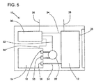
図5は、燃料電池システムの実施形態の概略図である。全構成要素が、不可欠であるわけではなく、燃料電池システムの構成要素は、必ずしも、図1に示されるように、配置されない(例えば、いくつかの構成要素は、燃料電池システムによって給電される装置内に位置してもよい)。燃料電池システム10は、燃料電池スタック12と、水素燃料をスタック12に提供するための可撤性水素発生器14とを含む。水素は、水素発生器14内の出口弁16を通って、かつスタック12への入口24を通って通過し、そこで、アノードによって、燃料として使用される。酸素等の別のガスは、入口26を通して、スタック12に流入し、そこで、カソードによって、酸化剤として使用される。スタック12は、電力出力28を通して、電気装置に提供される電気を産生する。水素発生器14内の反応物質は、水素を産生するように反応する。水素発生器14内の液体は、リザーバから反応エリアに移送され、そこで、水素が発生される。液体は、水素発生器筐体内または外に配置され得る、ポンプ22によって移送される。ポンプ22が、筐体内にある場合、必要とされる外部接続はより少ないが、ポンプ22が、外部ポンプである場合、使用済み水素発生器14が交換された後も使用され続けることができる。図5では、ポンプ22は、水素発生器14外に示される。液体は、出口弁18を通して、水素発生器14から、入口弁20を通して、水素発生器14内に逆圧送されることができる。燃料電池システム10は、ガス発生器14および/または燃料電池スタック12の動作を制御するために、随意の制御システムを含むことができる。制御システムの構成要素は、水素発生器14、燃料電池スタック12、燃料電池システムによって給電される装置、またはそれらの組み合わせ内に配置されることができる。制御システムは、コントローラ30を含むことができる。コントローラ30は、燃料電池システム10内に位置し得るが、図5に示されるように、燃料電池システム10内、または、例えば、電気装置内のいずれかの場所であることができる。コントローラ30は、通信ライン32を通して、ポンプ22と、通信ライン34を通して、スタック12と、通信ライン36を通して、水素発生器14と、および/または通信ライン38を通して、デバイスと通信することができる。電圧、電流、温度、圧力、および他のパラメータを監視するためのセンサは、それらの構成要素内に配置される、またはそれらと通信することができ、したがって、ガス発生は、それらのパラメータに基づいて、制御されることができる。
FIG. 5 is a schematic diagram of an embodiment of a fuel cell system. Not all components are essential and the components of the fuel cell system are not necessarily arranged as shown in FIG. 1 (eg, some components are powered by the fuel cell system) May be located within). The
(実施例1)
ポンプが、水および酸性水溶液を圧送するために、図4に示される実施形態に従って製造された。5ボルト直流モータおよび機械加工されたアルミニウムカムシャフトが、機械加工されたアルミニウムフレーム上に搭載された。機械加工されたTURCITE(R)プッシュロッドおよび成形されたSIFEL(R)ダイヤフラムシートが、使用された。ポンプ本体は、ULTEM(R)のブロックから機械加工された。弁バネは、316ステンレス鋼から作製され、弁カバーは、304ステンレス鋼であった。
Example 1
A pump was manufactured according to the embodiment shown in FIG. 4 to pump water and acidic aqueous solution. A 5-volt DC motor and a machined aluminum camshaft were mounted on a machined aluminum frame. Machined TURCITE® push rods and molded SIFEL® diaphragm sheets were used. The pump body was machined from a ULTEM® block. The valve spring was made from 316 stainless steel and the valve cover was 304 stainless steel.
ポンプ本体内のポンプチャンバの最大容積は、ポンプが待機位置にある状態で、0.06cm3であった。ポンプは、ポンプが66サイクル/分で動作時、0.04cm3/サイクルを送達可能であった。ポンプはまた、呼水のための液体をリザーバから引き込むために、3psi(211g/cm2)、および圧力を排出するために、8psi(562g/cm2)の吸引力を発生可能であった。 The maximum volume of the pump chamber in the pump body was 0.06 cm 3 with the pump in the standby position. The pump was capable of delivering 0.04 cm 3 / cycle when the pump was operating at 66 cycles / min. The pump also to draw liquid for priming the reservoir, 3psi (211g / cm 2) , and in order to discharge the pressure was capable of generating a suction force of 8psi (562g / cm 2).
(実施例2)
実施例1のポンプは、水素発生器と併用された。水素発生器は、筐体内に水を含有する液体リザーバを含んでいた。ポンプは、水素発生器外に位置し、リザーバから、筐体内の出口を通して、ポンプまで延在する、液体送給ラインと、ポンプから、筐体の入口を通して、水素化ホウ素ナトリウムおよび酸の固体混合物を含有する反応エリアまで延在する、液体供給ラインとを伴った。反応エリアに圧送された水は、酸の存在下、水素化ホウ素ナトリウムと反応し、水素ガスを産生した。水素ガスは、燃料として、水素−酸素燃料電池スタックに供給された。
(Example 2)
The pump of Example 1 was used in combination with a hydrogen generator. The hydrogen generator included a liquid reservoir containing water in the housing. The pump is located outside the hydrogen generator and extends from the reservoir, through an outlet in the enclosure, to the pump, and a solid mixture of sodium borohydride and acid from the pump through the enclosure inlet With a liquid supply line extending to the reaction area containing. The water pumped to the reaction area reacted with sodium borohydride in the presence of acid to produce hydrogen gas. Hydrogen gas was supplied to the hydrogen-oxygen fuel cell stack as fuel.
本発明によるポンプは、水素発生器のための液体を圧送するために好適であるが、また、他の用途において使用するためにも好適であり得る。 The pump according to the invention is suitable for pumping liquid for a hydrogen generator, but may also be suitable for use in other applications.
本明細書に引用される全ての参考文献は、その全体として、参照することによって本明細書に明示的に組み込まれる。参照することによって組み込まれる刊行物および特許または特許出願が、本明細書内に含有される開示に矛盾する限りにおいて、本明細書は、任意のそのような矛盾する資料に代わる、および/または優先するよう意図される。 All references cited herein are expressly incorporated herein by reference in their entirety. To the extent that the publications and patents or patent applications incorporated by reference contradict the disclosure contained herein, this specification shall be in lieu of any such conflicting material and / or priority. Intended to be.
種々の修正および改良が、開示される概念の精神から逸脱することなく、本発明に行なわれ得ることは、本発明を実践する者および当業者によって理解されるであろう。与えられる保護の範囲は、特許請求の範囲によりおよび法律によって許容される解釈の幅により判断されるものとする。 It will be understood by those skilled in the art and those skilled in the art that various modifications and improvements can be made to the present invention without departing from the spirit of the disclosed concept. The scope of protection afforded shall be determined by the claims and by the breadth of interpretation allowed by law.
Claims (19)
前記水素発生器は、
筐体と、
液体反応物質を含有し、前記筐体内に配置される液体リザーバと、
前記筐体内に配置される反応エリアと、
前記液体反応物質を前記液体リザーバから、液体流路を通して、前記反応エリアに圧送するように構成されるポンプと
を備え、
前記液体は、前記反応エリア内で反応し、水素ガスを放出可能であり、
前記ポンプは、ダイヤフラムポンプであり、
前記ポンプは、
ある容積を有するポンプチャンバと、
前記ポンプチャンバの一部を画定する第1のダイヤフラムと、
入口弁がその中に配置される、前記ポンプチャンバへの液体入口経路であって、前記入口弁は、閉鎖位置において、第2のダイヤフラムに対して付勢される、液体入口経路と、
出口弁がその中に配置される、前記ポンプチャンバからの液体出口経路であって、前記出口弁は、閉鎖位置において、第3のダイヤフラムに対して付勢される、液体出口経路と、
回転可能シャフトを有するモータと、
全てが前記回転可能シャフト上に配置される、第1のカム、第2のカム、および第3のカムと、
前記第1のカムと接触し、前記第1のカムと協働して、前記第1のダイヤフラムを可逆的に変位させ、前記ポンプチャンバ容積を減少させるように構成される第1のプッシュロッドと、
前記第2のカムと接触し、前記第2のカムと協働して、前記第2のダイヤフラムを可逆的に変位させ、前記入口弁を開放させるように構成される第2のプッシュロッドと、
前記第3のカムと接触し、前記第3のカムと協働して、前記第3のダイヤフラムを可逆的に変位させ、前記出口弁を開放させるように構成される第3のプッシュロッドと
を備え、
前記液体リザーバと前記反応エリアとの間の液体流路内の全ての弁は、機械作動式弁である、水素発生器。 A hydrogen generator,
The hydrogen generator is
A housing,
A liquid reservoir containing a liquid reactant and disposed within the housing;
A reaction area disposed within the housing;
A pump configured to pump the liquid reactant from the liquid reservoir through the liquid flow path to the reaction area;
The liquid reacts in the reaction area and is capable of releasing hydrogen gas;
The pump is a diaphragm pump;
The pump is
A pump chamber having a volume;
A first diaphragm defining a portion of the pump chamber;
A liquid inlet path to the pump chamber in which an inlet valve is disposed, wherein the inlet valve is biased against a second diaphragm in a closed position;
A liquid outlet path from the pump chamber in which an outlet valve is disposed, wherein the outlet valve is biased against a third diaphragm in a closed position;
A motor having a rotatable shaft;
A first cam, a second cam, and a third cam, all disposed on the rotatable shaft;
A first push rod configured to contact the first cam and cooperate with the first cam to reversibly displace the first diaphragm and reduce the pump chamber volume; ,
A second push rod configured to contact the second cam and cooperate with the second cam to reversibly displace the second diaphragm and open the inlet valve;
A third push rod configured to contact the third cam and cooperate with the third cam to reversibly displace the third diaphragm and open the outlet valve; Prepared,
The hydrogen generator, wherein all valves in the liquid flow path between the liquid reservoir and the reaction area are mechanically actuated valves.
Applications Claiming Priority (3)
| Application Number | Priority Date | Filing Date | Title |
|---|---|---|---|
| US13/278,594 US8545195B2 (en) | 2011-10-21 | 2011-10-21 | Hydrogen generator with pump |
| US13/278,594 | 2011-10-21 | ||
| PCT/US2012/060475 WO2013059220A1 (en) | 2011-10-21 | 2012-10-17 | Hydrogen generator with diaphragm pump |
Publications (2)
| Publication Number | Publication Date |
|---|---|
| JP2014532824A true JP2014532824A (en) | 2014-12-08 |
| JP2014532824A5 JP2014532824A5 (en) | 2015-12-03 |
Family
ID=47138177
Family Applications (1)
| Application Number | Title | Priority Date | Filing Date |
|---|---|---|---|
| JP2014537156A Ceased JP2014532824A (en) | 2011-10-21 | 2012-10-17 | Hydrogen generator with diaphragm pump |
Country Status (5)
| Country | Link |
|---|---|
| US (1) | US8545195B2 (en) |
| EP (1) | EP2769434B1 (en) |
| JP (1) | JP2014532824A (en) |
| CN (1) | CN104040774A (en) |
| WO (1) | WO2013059220A1 (en) |
Families Citing this family (7)
| Publication number | Priority date | Publication date | Assignee | Title |
|---|---|---|---|---|
| US20140193735A1 (en) * | 2013-01-04 | 2014-07-10 | Lilliputian Systems, Inc. | Low Vibration Linear Motor Systems |
| US9765713B2 (en) * | 2014-07-11 | 2017-09-19 | Huan-Hsin Kou | Hydrogen fuel assist device for an internal combustion engine system |
| CN106955805B (en) * | 2016-01-08 | 2020-04-28 | 深圳市华匠技术有限公司 | Diaphragm pump water gun |
| EP4039288A1 (en) * | 2016-03-18 | 2022-08-10 | DEKA Products Limited Partnership | Pressure control gaskets for operating pump cassette membranes |
| WO2019010324A1 (en) | 2017-07-06 | 2019-01-10 | Modular Medical, Inc. | Medical pump with flow control |
| US20220170452A1 (en) * | 2019-08-13 | 2022-06-02 | Hewlett-Packard Development Company, L.P. | Fluid ejection apparatus for discreet packet transfer of fluid |
| US20210170094A1 (en) * | 2019-12-06 | 2021-06-10 | Quasuras, Inc. | Training cartridge for medical pump systems |
Citations (3)
| Publication number | Priority date | Publication date | Assignee | Title |
|---|---|---|---|---|
| JPS63192447A (en) * | 1987-10-02 | 1988-08-09 | ミネソタ マイニング アンド マニュファクチュアリング カンパニー | Non-pulsating iv pump |
| JP2005273865A (en) * | 2004-03-26 | 2005-10-06 | Shimadzu Corp | Valve and liquid transfer pump employing it |
| JP2010517911A (en) * | 2007-02-02 | 2010-05-27 | ソシエテ ビック | Hydrogen gas generator |
Family Cites Families (20)
| Publication number | Priority date | Publication date | Assignee | Title |
|---|---|---|---|---|
| SE380445B (en) | 1973-11-23 | 1975-11-10 | Bjoerklund K B | PROCEDURE FOR INTERMITTENT DOSAGE OF SMALL VOLUMES AND DEVICE FOR PERFORMING THE PROCEDURE |
| US4236880A (en) * | 1979-03-09 | 1980-12-02 | Archibald Development Labs, Inc. | Nonpulsating IV pump and disposable pump chamber |
| US4613304A (en) | 1982-10-21 | 1986-09-23 | Meyer Stanley A | Gas electrical hydrogen generator |
| US6280867B1 (en) | 1997-12-05 | 2001-08-28 | Griff Consulting, Inc. | Apparatus for pumping a fluid in a fuel cell system |
| JP2002257050A (en) | 2001-03-02 | 2002-09-11 | Nikkiso Co Ltd | Diaphragm pump |
| CA2347646A1 (en) | 2001-05-07 | 2002-11-07 | Mohammed Mali | Hydrogen generation |
| US7691527B2 (en) | 2002-04-24 | 2010-04-06 | Petillo Phillip J | Method and apparatus for generating hydrogen |
| US7097813B2 (en) | 2002-06-21 | 2006-08-29 | Hewlett-Packard Development Company, L.P. | Hydrogen generating apparatus |
| JP2006114398A (en) | 2004-10-15 | 2006-04-27 | Mikuni Corp | Fuel cell system |
| US20090148321A1 (en) | 2004-11-30 | 2009-06-11 | Nidec Sankyo Corporation | Pump device and fuel cell |
| KR100725691B1 (en) | 2004-11-30 | 2007-06-07 | 니혼 덴산 산쿄 가부시키가이샤 | Pump apparatus using linear actuator |
| US20070011251A1 (en) | 2004-12-09 | 2007-01-11 | Mcnamara Kevin W | Fuel cartridge for fuel cell power systems and methods for power generation |
| US8187758B2 (en) | 2005-08-11 | 2012-05-29 | Ardica Technologies Inc. | Fuel cell apparatus with a split pump |
| JP2007239737A (en) | 2006-02-13 | 2007-09-20 | Nidec Sankyo Corp | Mixing pump device and fuel cell |
| US20070271844A1 (en) | 2006-04-12 | 2007-11-29 | Mohring Richard M | Hydrogen fuel cartridge and methods for hydrogen generation |
| JP2007287475A (en) | 2006-04-17 | 2007-11-01 | Nitto Denko Corp | Liquid quantitative discharge device and liquid quantitative discharge method |
| US8087906B2 (en) * | 2007-08-01 | 2012-01-03 | Carefusion 303, Inc. | Fluid pump with disposable component |
| US20090104481A1 (en) * | 2007-10-18 | 2009-04-23 | Mohring Richard M | Methods and devices for hydrogen generation |
| GB0910734D0 (en) * | 2009-06-22 | 2009-08-05 | 3M Innovative Properties Co | Method of bonding a fluoropolymer using a silane containing bonding promoter |
| WO2012058687A2 (en) | 2010-10-29 | 2012-05-03 | Ardica Technologies | Pump assembly for a fuel cell system |
-
2011
- 2011-10-21 US US13/278,594 patent/US8545195B2/en not_active Expired - Fee Related
-
2012
- 2012-10-17 CN CN201280062888.0A patent/CN104040774A/en active Pending
- 2012-10-17 WO PCT/US2012/060475 patent/WO2013059220A1/en active Application Filing
- 2012-10-17 JP JP2014537156A patent/JP2014532824A/en not_active Ceased
- 2012-10-17 EP EP12781225.3A patent/EP2769434B1/en not_active Not-in-force
Patent Citations (3)
| Publication number | Priority date | Publication date | Assignee | Title |
|---|---|---|---|---|
| JPS63192447A (en) * | 1987-10-02 | 1988-08-09 | ミネソタ マイニング アンド マニュファクチュアリング カンパニー | Non-pulsating iv pump |
| JP2005273865A (en) * | 2004-03-26 | 2005-10-06 | Shimadzu Corp | Valve and liquid transfer pump employing it |
| JP2010517911A (en) * | 2007-02-02 | 2010-05-27 | ソシエテ ビック | Hydrogen gas generator |
Also Published As
| Publication number | Publication date |
|---|---|
| US20130101910A1 (en) | 2013-04-25 |
| WO2013059220A1 (en) | 2013-04-25 |
| EP2769434A1 (en) | 2014-08-27 |
| CN104040774A (en) | 2014-09-10 |
| US8545195B2 (en) | 2013-10-01 |
| EP2769434B1 (en) | 2016-01-06 |
Similar Documents
| Publication | Publication Date | Title |
|---|---|---|
| EP2769434B1 (en) | Hydrogen generator with diaphragm pump | |
| EP1396471B1 (en) | Hydrogen generating apparatus | |
| TWI257731B (en) | Cartridge with fuel supply and membrane electrode assembly stack | |
| CN101138119A (en) | Fuel cell systems and related method | |
| WO2013011609A1 (en) | Direct oxidation fuel cell system | |
| CN103081195A (en) | Electrochemically actuated valve | |
| JP4149728B2 (en) | Fuel cell fuel supply cartridge and fuel cell comprising the cartridge | |
| JP5105756B2 (en) | Fuel cell | |
| JPWO2008143020A1 (en) | Polymer electrolyte fuel cell | |
| WO2010013711A1 (en) | Fuel cell system and electronic device | |
| JP2007317496A (en) | Fuel cell power generation system | |
| WO2008023634A1 (en) | Fuel cell | |
| JP2005203355A (en) | Fuel cell system and method of generating electric power in fuel cell system | |
| JP2009181861A (en) | Fuel cell | |
| JP4956589B2 (en) | Fuel cell | |
| JP5005253B2 (en) | Fuel cell system | |
| JPWO2008102424A1 (en) | Fuel cell | |
| WO2009139334A1 (en) | Fuel cartridge and fuel cell system | |
| JP2011113912A (en) | Fuel cell | |
| JP2009123443A (en) | Fuel cell | |
| CN1809941A (en) | Fuel cell cartridge for portable electronic device | |
| JP2010244919A (en) | Fuel cell system, and control method therefor | |
| JP2010102902A (en) | Fuel cell | |
| JP2004319388A (en) | Fuel container for fuel cell, fuel supply device, and fuel cell for portable apparatus | |
| JPWO2008023633A1 (en) | Fuel cell |
Legal Events
| Date | Code | Title | Description |
|---|---|---|---|
| A521 | Written amendment |
Free format text: JAPANESE INTERMEDIATE CODE: A523 Effective date: 20151016 |
|
| A621 | Written request for application examination |
Free format text: JAPANESE INTERMEDIATE CODE: A621 Effective date: 20151016 |
|
| A131 | Notification of reasons for refusal |
Free format text: JAPANESE INTERMEDIATE CODE: A131 Effective date: 20160719 |
|
| A977 | Report on retrieval |
Free format text: JAPANESE INTERMEDIATE CODE: A971007 Effective date: 20160721 |
|
| A521 | Written amendment |
Free format text: JAPANESE INTERMEDIATE CODE: A523 Effective date: 20160928 |
|
| A01 | Written decision to grant a patent or to grant a registration (utility model) |
Free format text: JAPANESE INTERMEDIATE CODE: A01 Effective date: 20170111 |
|
| A045 | Written measure of dismissal of application [lapsed due to lack of payment] |
Free format text: JAPANESE INTERMEDIATE CODE: A045 Effective date: 20170525 |