JP2014531743A5 - - Google Patents
Download PDFInfo
- Publication number
- JP2014531743A5 JP2014531743A5 JP2014527148A JP2014527148A JP2014531743A5 JP 2014531743 A5 JP2014531743 A5 JP 2014531743A5 JP 2014527148 A JP2014527148 A JP 2014527148A JP 2014527148 A JP2014527148 A JP 2014527148A JP 2014531743 A5 JP2014531743 A5 JP 2014531743A5
- Authority
- JP
- Japan
- Prior art keywords
- target
- sensors
- light beam
- amplified light
- mixture
- Prior art date
- Legal status (The legal status is an assumption and is not a legal conclusion. Google has not performed a legal analysis and makes no representation as to the accuracy of the status listed.)
- Granted
Links
- 239000000203 mixture Substances 0.000 claims description 9
- 239000000463 material Substances 0.000 claims description 6
- 210000002381 Plasma Anatomy 0.000 claims description 3
- 230000005670 electromagnetic radiation Effects 0.000 claims 4
- 230000003287 optical Effects 0.000 claims 4
- 238000003384 imaging method Methods 0.000 claims 3
- 239000012530 fluid Substances 0.000 claims 1
- 238000005070 sampling Methods 0.000 claims 1
Images


Description
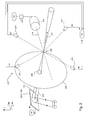
すなわち、RAy信号は、増幅光ビーム210の駆動軸線212のターゲット領域205からのオフセット(これは、主軸線211により表すことができる)を判断するのに使用することができる。例えば、図5Aに示すように、駆動軸線212は、エネルギセンサ271及び274により近く、従って、RAyは、変曲値705よりも大きく、それぞれエネルギセンサ271、274からのエネルギ信号E1及びE4が、それぞれエネルギセンサ272、273からのエネルギ信号E2及びE3よりも大きいことを示している。別の例として、図5Bに示すように、駆動軸線212は、エネルギセンサ272及び273により近く、従って、RAyは、変曲値705を下回り、従って、エネルギ信号E2及びE3がエネルギ信号エル及びE4よりも大きいことを示している。図5Cを参照すると、駆動軸線212は、エネルギセンサ273及び274からy方向に沿ってほぼ等距離にあり、かつエネルギセンサ271及び272からy方向に沿ってほぼ等距離にある。従って、RAyは、変曲値705に近づく。
That is, the RAy signal can be used to determine the offset of the amplified
エネルギセンサ271、272、273、274が、y方向に完全に位置合わせされ、かつ主軸線211に沿った信号が、等しいエネルギをエネルギセンサ271、272、273、274の各々に供給するように較正された場合に、RAyの変曲値705は0に近づくであろう。
The
例えば、ビーム送出システム内の要素は、y方向に沿って調節される時に、駆動軸線212とターゲット領域205との間の相対的なアラインメントを変える(これは、主軸線211により表される)。全エネルギEtotは、要素の特定の位置605に対して最大値に到達する。従って、ビーム送出システム内の要素の位置を調節することにより、ターゲット混合物と増幅光ビームの駆動軸線との間の相対的半径方向距離も調節され、それによってプラズマ状態のターゲット材料によって放出されるEUV放射線を増大させてより多くのEUV光を光源100から生成する。
For example, elements in the beam delivery system change the relative alignment between the
Claims (11)
前記パルスの増幅光ビームをターゲット領域に向けて誘導するビーム送出システムと、
ターゲット材料を含むターゲット混合物を前記ターゲット領域に供給するターゲット材料送出システムと、
前記ターゲット領域と交差する主軸線から異なる位置で半径方向に分離される2以上のセンサであって、前記パルスの増幅光ビームが前記ターゲット混合物と交差した時にプラズマ状態の前記ターゲット材料から放出された紫外電磁放射線のエネルギを検出する2以上のセンサと、
前記2以上のセンサからの出力を受け取り、検出した前記エネルギを解析して該解析に基づいて前記ターゲット混合物と前記ターゲット領域内の前記駆動軸線との間の相対的半径方向アラインメントを推定し、かつ前記ターゲット領域における前記ターゲット混合物に対する前記増幅光ビームの半径方向アラインメントを調節し、それによって前記ターゲット混合物と前記ターゲット領域内の前記駆動軸線との間の相対的半径方向距離を調節する信号を前記ビーム送出システムに出力するコントローラと、を備える装置。 A drive laser system for generating an amplified light beam of pulses traveling along a drive axis;
A beam delivery system for directing the amplified light beam of pulses toward a target area;
A target material delivery system for supplying a target mixture containing the target material to the target region;
Two or more sensors radially separated at different positions from a main axis intersecting the target region, wherein the amplified light beam of the pulse is emitted from the target material in a plasma state when intersecting the target mixture Two or more sensors for detecting the energy of ultraviolet electromagnetic radiation;
Receiving output from the two or more sensors, analyzing the detected energy and estimating a relative radial alignment between the target mixture and the drive axis in the target region based on the analysis; and Adjusting the radial alignment of the amplified light beam with respect to the target mixture in the target region, thereby adjusting the relative radial distance between the target mixture and the drive axis in the target region, A controller for outputting to a delivery system.
前記コントローラはまた、前記撮像デバイスからの出力を受け取り、かつ前記撮像デバイスから受け取った前記出力にも基づいて前記相対的半径方向アラインメントを推定する、請求項1に記載の装置。 An imaging device for capturing an optical image of the laser beam reflected back from the target mixture toward the drive laser system;
The apparatus of claim 1, wherein the controller also receives output from the imaging device and estimates the relative radial alignment based on the output received from the imaging device.
Applications Claiming Priority (5)
| Application Number | Priority Date | Filing Date | Title |
|---|---|---|---|
| US201161525561P | 2011-08-19 | 2011-08-19 | |
| US61/525,561 | 2011-08-19 | ||
| US13/249,504 US8993976B2 (en) | 2011-08-19 | 2011-09-30 | Energy sensors for light beam alignment |
| US13/249,504 | 2011-09-30 | ||
| PCT/US2012/046093 WO2013028272A1 (en) | 2011-08-19 | 2012-07-10 | Energy sensors for light beam alignment |
Publications (3)
| Publication Number | Publication Date |
|---|---|
| JP2014531743A JP2014531743A (en) | 2014-11-27 |
| JP2014531743A5 true JP2014531743A5 (en) | 2015-08-13 |
| JP5977828B2 JP5977828B2 (en) | 2016-08-24 |
Family
ID=47711970
Family Applications (1)
| Application Number | Title | Priority Date | Filing Date |
|---|---|---|---|
| JP2014527148A Active JP5977828B2 (en) | 2011-08-19 | 2012-07-10 | Energy sensor for optical beam alignment |
Country Status (7)
| Country | Link |
|---|---|
| US (1) | US8993976B2 (en) |
| EP (1) | EP2745650A4 (en) |
| JP (1) | JP5977828B2 (en) |
| KR (1) | KR101949839B1 (en) |
| CN (1) | CN103748967B (en) |
| TW (1) | TWI536869B (en) |
| WO (1) | WO2013028272A1 (en) |
Families Citing this family (27)
| Publication number | Priority date | Publication date | Assignee | Title |
|---|---|---|---|---|
| US9148941B2 (en) * | 2013-01-22 | 2015-09-29 | Asml Netherlands B.V. | Thermal monitor for an extreme ultraviolet light source |
| US9000405B2 (en) * | 2013-03-15 | 2015-04-07 | Asml Netherlands B.V. | Beam position control for an extreme ultraviolet light source |
| US9558858B2 (en) * | 2013-08-14 | 2017-01-31 | Kla-Tencor Corporation | System and method for imaging a sample with a laser sustained plasma illumination output |
| JP6220879B2 (en) | 2013-08-27 | 2017-10-25 | ギガフォトン株式会社 | Extreme ultraviolet light generation device and extreme ultraviolet light generation system |
| US9271381B2 (en) * | 2014-02-10 | 2016-02-23 | Asml Netherlands B.V. | Methods and apparatus for laser produced plasma EUV light source |
| WO2015172816A1 (en) * | 2014-05-13 | 2015-11-19 | Trumpf Laser- Und Systemtechnik Gmbh | Device for monitoring the orientation of a laser beam and euv radiation-generating device comprising same |
| WO2016139022A1 (en) * | 2015-03-03 | 2016-09-09 | Asml Netherlands B.V. | Radiation sensor apparatus |
| US9927292B2 (en) * | 2015-04-23 | 2018-03-27 | Asml Netherlands B.V. | Beam position sensor |
| WO2017056324A1 (en) | 2015-10-02 | 2017-04-06 | ギガフォトン株式会社 | Euv light generation system |
| WO2017077584A1 (en) | 2015-11-03 | 2017-05-11 | ギガフォトン株式会社 | Extreme uv light generator |
| US9536631B1 (en) * | 2015-11-19 | 2017-01-03 | Asml Netherlands B.V. | Systems and methods to avoid instability conditions in a source plasma chamber |
| WO2017090167A1 (en) * | 2015-11-26 | 2017-06-01 | ギガフォトン株式会社 | Extreme ultraviolet light generation device |
| WO2017130346A1 (en) * | 2016-01-28 | 2017-08-03 | ギガフォトン株式会社 | Extreme ultraviolet light generation device |
| WO2017154111A1 (en) * | 2016-03-08 | 2017-09-14 | ギガフォトン株式会社 | Extreme ultraviolet light generation device |
| WO2017163345A1 (en) * | 2016-03-23 | 2017-09-28 | ギガフォトン株式会社 | Extreme ultraviolet light generation apparatus, and method for controlling gravity center position of extreme ultraviolet light |
| US9778022B1 (en) | 2016-09-14 | 2017-10-03 | Asml Netherlands B.V. | Determining moving properties of a target in an extreme ultraviolet light source |
| US10149375B2 (en) | 2016-09-14 | 2018-12-04 | Asml Netherlands B.V. | Target trajectory metrology in an extreme ultraviolet light source |
| JP6775606B2 (en) * | 2017-01-12 | 2020-10-28 | ギガフォトン株式会社 | Extreme ultraviolet light generation system |
| WO2018131146A1 (en) * | 2017-01-13 | 2018-07-19 | ギガフォトン株式会社 | Extreme ultraviolet light generation system |
| CN110462522B (en) * | 2017-03-20 | 2021-10-08 | Asml荷兰有限公司 | Lithographic system, EUV radiation source, lithographic scanning apparatus and control system |
| WO2018179068A1 (en) * | 2017-03-27 | 2018-10-04 | ギガフォトン株式会社 | Euv light generation device, and method for controlling center of gravity position of euv light |
| NL2021836A (en) | 2017-10-26 | 2019-05-01 | Asml Netherlands Bv | System for monitoring a plasma |
| CN111955058A (en) * | 2018-04-03 | 2020-11-17 | Asml荷兰有限公司 | Spatial modulation of light beams |
| CN112771999A (en) * | 2018-09-25 | 2021-05-07 | Asml荷兰有限公司 | Laser system for target metrology and modification in EUV light sources |
| CN112930714A (en) * | 2018-10-26 | 2021-06-08 | Asml荷兰有限公司 | Monitoring light emission |
| TW202041103A (en) | 2019-01-30 | 2020-11-01 | 荷蘭商Asml荷蘭公司 | Determining moving properties of a target in an extreme ultraviolet light source |
| CN112629654A (en) * | 2020-12-11 | 2021-04-09 | 苏州瑞派宁科技有限公司 | Detection device, laser plasma light source and adjusting method thereof |
Family Cites Families (17)
| Publication number | Priority date | Publication date | Assignee | Title |
|---|---|---|---|---|
| US7598509B2 (en) | 2004-11-01 | 2009-10-06 | Cymer, Inc. | Laser produced plasma EUV light source |
| US7439530B2 (en) | 2005-06-29 | 2008-10-21 | Cymer, Inc. | LPP EUV light source drive laser system |
| DE10251435B3 (en) * | 2002-10-30 | 2004-05-27 | Xtreme Technologies Gmbh | Radiation source for extreme UV radiation for photolithographic exposure applications for semiconductor chip manufacture |
| US7217941B2 (en) * | 2003-04-08 | 2007-05-15 | Cymer, Inc. | Systems and methods for deflecting plasma-generated ions to prevent the ions from reaching an internal component of an EUV light source |
| US7217940B2 (en) * | 2003-04-08 | 2007-05-15 | Cymer, Inc. | Collector for EUV light source |
| JP4917014B2 (en) * | 2004-03-10 | 2012-04-18 | サイマー インコーポレイテッド | EUV light source |
| US7164144B2 (en) | 2004-03-10 | 2007-01-16 | Cymer Inc. | EUV light source |
| JP4683231B2 (en) * | 2004-06-24 | 2011-05-18 | 株式会社ニコン | EUV LIGHT SOURCE, EUV EXPOSURE APPARATUS, AND METHOD FOR MANUFACTURING SEMICONDUCTOR DEVICE |
| US8766212B2 (en) * | 2006-07-19 | 2014-07-01 | Asml Netherlands B.V. | Correction of spatial instability of an EUV source by laser beam steering |
| US7633070B2 (en) | 2006-12-18 | 2009-12-15 | Kla-Tencor Technologies Corporation | Substrate processing apparatus and method |
| NL1036803A (en) * | 2008-09-09 | 2010-03-15 | Asml Netherlands Bv | RADIATION SYSTEM AND LITHOGRAPHIC EQUIPMENT. |
| JP5553833B2 (en) * | 2008-09-11 | 2014-07-16 | エーエスエムエル ネザーランズ ビー.ブイ. | Radiation source and lithographic apparatus |
| US8138487B2 (en) | 2009-04-09 | 2012-03-20 | Cymer, Inc. | System, method and apparatus for droplet catcher for prevention of backsplash in a EUV generation chamber |
| JP5252586B2 (en) * | 2009-04-15 | 2013-07-31 | ウシオ電機株式会社 | Laser drive light source |
| JP5612579B2 (en) | 2009-07-29 | 2014-10-22 | ギガフォトン株式会社 | Extreme ultraviolet light source device, control method of extreme ultraviolet light source device, and recording medium recording the program |
| US8000212B2 (en) | 2009-12-15 | 2011-08-16 | Cymer, Inc. | Metrology for extreme ultraviolet light source |
| US8173985B2 (en) | 2009-12-15 | 2012-05-08 | Cymer, Inc. | Beam transport system for extreme ultraviolet light source |
-
2011
- 2011-09-30 US US13/249,504 patent/US8993976B2/en active Active
-
2012
- 2012-07-10 KR KR1020147007197A patent/KR101949839B1/en active IP Right Grant
- 2012-07-10 CN CN201280040305.4A patent/CN103748967B/en active Active
- 2012-07-10 WO PCT/US2012/046093 patent/WO2013028272A1/en active Application Filing
- 2012-07-10 EP EP12825084.2A patent/EP2745650A4/en not_active Withdrawn
- 2012-07-10 JP JP2014527148A patent/JP5977828B2/en active Active
- 2012-08-01 TW TW101127771A patent/TWI536869B/en active
Similar Documents
| Publication | Publication Date | Title |
|---|---|---|
| JP2014531743A5 (en) | ||
| JP5977828B2 (en) | Energy sensor for optical beam alignment | |
| US9201138B2 (en) | Photon detector with a paralyzable photon-sensitive element, in particular SPAD, and distance measuring device comprising said type of photon detector | |
| JP2012523694A5 (en) | ||
| KR102618012B1 (en) | Determining moving properties of a target in an extreme ultraviolet light source | |
| JP2013535824A5 (en) | ||
| US10681797B2 (en) | Target trajectory metrology in an extreme ultraviolet light source | |
| TWI788998B (en) | Target expansion rate control in an extreme ultraviolet light source | |
| TW202127151A (en) | Extreme ultraviolet (euv) optical source, apparatus for an euv light source and optical isolation method | |
| KR102214861B1 (en) | Beam position control for an extreme ultraviolet light source | |
| JP2016512383A5 (en) | ||
| JP6344845B2 (en) | Laser distance measuring device | |
| US8169598B2 (en) | Rangefinder | |
| WO2018228354A1 (en) | Parfocal control system for emitted laser and target detection light | |
| US11737199B2 (en) | Device and method for measuring the beam angle of a light beam guided by a beam guiding optical unit | |
| JP2017124413A (en) | Laser device and laser irradiation method | |
| IL165167A0 (en) | Laser range detection |