JP2014527426A - Seal container and method of using the seal container - Google Patents
Seal container and method of using the seal container Download PDFInfo
- Publication number
- JP2014527426A JP2014527426A JP2014521746A JP2014521746A JP2014527426A JP 2014527426 A JP2014527426 A JP 2014527426A JP 2014521746 A JP2014521746 A JP 2014521746A JP 2014521746 A JP2014521746 A JP 2014521746A JP 2014527426 A JP2014527426 A JP 2014527426A
- Authority
- JP
- Japan
- Prior art keywords
- container
- cover
- food
- liquid
- transfer device
- Prior art date
- Legal status (The legal status is an assumption and is not a legal conclusion. Google has not performed a legal analysis and makes no representation as to the accuracy of the status listed.)
- Pending
Links
Images


Classifications
-
- B—PERFORMING OPERATIONS; TRANSPORTING
- B65—CONVEYING; PACKING; STORING; HANDLING THIN OR FILAMENTARY MATERIAL
- B65D—CONTAINERS FOR STORAGE OR TRANSPORT OF ARTICLES OR MATERIALS, e.g. BAGS, BARRELS, BOTTLES, BOXES, CANS, CARTONS, CRATES, DRUMS, JARS, TANKS, HOPPERS, FORWARDING CONTAINERS; ACCESSORIES, CLOSURES, OR FITTINGS THEREFOR; PACKAGING ELEMENTS; PACKAGES
- B65D47/00—Closures with filling and discharging, or with discharging, devices
- B65D47/36—Closures with frangible parts adapted to be pierced, torn, or removed, to provide discharge openings
-
- A—HUMAN NECESSITIES
- A47—FURNITURE; DOMESTIC ARTICLES OR APPLIANCES; COFFEE MILLS; SPICE MILLS; SUCTION CLEANERS IN GENERAL
- A47J—KITCHEN EQUIPMENT; COFFEE MILLS; SPICE MILLS; APPARATUS FOR MAKING BEVERAGES
- A47J31/00—Apparatus for making beverages
- A47J31/40—Beverage-making apparatus with dispensing means for adding a measured quantity of ingredients, e.g. coffee, water, sugar, cocoa, milk, tea
- A47J31/407—Beverage-making apparatus with dispensing means for adding a measured quantity of ingredients, e.g. coffee, water, sugar, cocoa, milk, tea with ingredient-containing cartridges; Cartridge-perforating means
-
- B—PERFORMING OPERATIONS; TRANSPORTING
- B65—CONVEYING; PACKING; STORING; HANDLING THIN OR FILAMENTARY MATERIAL
- B65D—CONTAINERS FOR STORAGE OR TRANSPORT OF ARTICLES OR MATERIALS, e.g. BAGS, BARRELS, BOTTLES, BOXES, CANS, CARTONS, CRATES, DRUMS, JARS, TANKS, HOPPERS, FORWARDING CONTAINERS; ACCESSORIES, CLOSURES, OR FITTINGS THEREFOR; PACKAGING ELEMENTS; PACKAGES
- B65D79/00—Kinds or details of packages, not otherwise provided for
-
- B—PERFORMING OPERATIONS; TRANSPORTING
- B65—CONVEYING; PACKING; STORING; HANDLING THIN OR FILAMENTARY MATERIAL
- B65D—CONTAINERS FOR STORAGE OR TRANSPORT OF ARTICLES OR MATERIALS, e.g. BAGS, BARRELS, BOTTLES, BOXES, CANS, CARTONS, CRATES, DRUMS, JARS, TANKS, HOPPERS, FORWARDING CONTAINERS; ACCESSORIES, CLOSURES, OR FITTINGS THEREFOR; PACKAGING ELEMENTS; PACKAGES
- B65D85/00—Containers, packaging elements or packages, specially adapted for particular articles or materials
- B65D85/70—Containers, packaging elements or packages, specially adapted for particular articles or materials for materials not otherwise provided for
- B65D85/804—Disposable containers or packages with contents which are mixed, infused or dissolved in situ, i.e. without having been previously removed from the package
- B65D85/8043—Packages adapted to allow liquid to pass through the contents
-
- Y—GENERAL TAGGING OF NEW TECHNOLOGICAL DEVELOPMENTS; GENERAL TAGGING OF CROSS-SECTIONAL TECHNOLOGIES SPANNING OVER SEVERAL SECTIONS OF THE IPC; TECHNICAL SUBJECTS COVERED BY FORMER USPC CROSS-REFERENCE ART COLLECTIONS [XRACs] AND DIGESTS
- Y10—TECHNICAL SUBJECTS COVERED BY FORMER USPC
- Y10T—TECHNICAL SUBJECTS COVERED BY FORMER US CLASSIFICATION
- Y10T428/00—Stock material or miscellaneous articles
- Y10T428/31504—Composite [nonstructural laminate]
- Y10T428/3154—Of fluorinated addition polymer from unsaturated monomers
-
- Y—GENERAL TAGGING OF NEW TECHNOLOGICAL DEVELOPMENTS; GENERAL TAGGING OF CROSS-SECTIONAL TECHNOLOGIES SPANNING OVER SEVERAL SECTIONS OF THE IPC; TECHNICAL SUBJECTS COVERED BY FORMER USPC CROSS-REFERENCE ART COLLECTIONS [XRACs] AND DIGESTS
- Y10—TECHNICAL SUBJECTS COVERED BY FORMER USPC
- Y10T—TECHNICAL SUBJECTS COVERED BY FORMER US CLASSIFICATION
- Y10T428/00—Stock material or miscellaneous articles
- Y10T428/31504—Composite [nonstructural laminate]
- Y10T428/31652—Of asbestos
- Y10T428/31663—As siloxane, silicone or silane
-
- Y—GENERAL TAGGING OF NEW TECHNOLOGICAL DEVELOPMENTS; GENERAL TAGGING OF CROSS-SECTIONAL TECHNOLOGIES SPANNING OVER SEVERAL SECTIONS OF THE IPC; TECHNICAL SUBJECTS COVERED BY FORMER USPC CROSS-REFERENCE ART COLLECTIONS [XRACs] AND DIGESTS
- Y10—TECHNICAL SUBJECTS COVERED BY FORMER USPC
- Y10T—TECHNICAL SUBJECTS COVERED BY FORMER US CLASSIFICATION
- Y10T428/00—Stock material or miscellaneous articles
- Y10T428/31504—Composite [nonstructural laminate]
- Y10T428/31855—Of addition polymer from unsaturated monomers
- Y10T428/31909—Next to second addition polymer from unsaturated monomers
- Y10T428/31913—Monoolefin polymer
-
- Y—GENERAL TAGGING OF NEW TECHNOLOGICAL DEVELOPMENTS; GENERAL TAGGING OF CROSS-SECTIONAL TECHNOLOGIES SPANNING OVER SEVERAL SECTIONS OF THE IPC; TECHNICAL SUBJECTS COVERED BY FORMER USPC CROSS-REFERENCE ART COLLECTIONS [XRACs] AND DIGESTS
- Y10—TECHNICAL SUBJECTS COVERED BY FORMER USPC
- Y10T—TECHNICAL SUBJECTS COVERED BY FORMER US CLASSIFICATION
- Y10T428/00—Stock material or miscellaneous articles
- Y10T428/31504—Composite [nonstructural laminate]
- Y10T428/31855—Of addition polymer from unsaturated monomers
- Y10T428/31938—Polymer of monoethylenically unsaturated hydrocarbon
Abstract
ある容器が提供され、その容器は、(a)少なくとも1枚のエラストマー層を備えるカバーと、(b)容器内に収容された食物成分であって、液体食物成分又は固体食物成分であり、更には、固体食物成分は、液体と接触すると流体食品を生じるように構成されている食物成分とを備え、カバーは、液体食物成分又は流体食品を注入又は抽出するための少なくとも1つの液体移送装置によって穴開けされるように構成されており、更には、少なくとも1つの液体移送装置が容器から取除かれると、カバーは、液体、液体食物成分、流体食品、又はそれらの組合わせのいずれの漏れに対しても、カバー自体を再シールするように構成されている容器。また、プランジャとばねとを備える容器が提供される。上記の容器を使用する方法が提供される。A container is provided, the container comprising: (a) a cover comprising at least one elastomer layer; and (b) a food ingredient contained in the container, which is a liquid food ingredient or a solid food ingredient, The solid food component comprises a food component configured to produce a fluid food product upon contact with the liquid, and the cover is provided by at least one liquid transfer device for injecting or extracting the liquid food component or fluid food product Further, when the at least one liquid transfer device is removed from the container, the cover is configured to leak any liquid, liquid food ingredient, fluid food, or combinations thereof. Again, a container that is configured to reseal the cover itself. A container comprising a plunger and a spring is also provided. A method of using the container is provided.
Description
本開示は、流体が容器に注入されるときに流体食品を作るための、液体食物成分又は固体食物成分を収容したシール容器に関する。本開示はまた、液体移送装置を取除く際の液体食物成分又は液体食品の漏れを防止するためのカバーを備えたシール容器に関する。 The present disclosure relates to a sealed container containing a liquid food ingredient or a solid food ingredient for making a fluid food product when fluid is injected into the container. The present disclosure also relates to a sealed container with a cover for preventing leakage of liquid food ingredients or liquid food upon removal of the liquid transfer device.
挽いた焙煎コーヒー、茶、インスタントコーヒー、挽いたコーヒーとインスタントコーヒーとの混合物、チョコレートをベースにした製品、又は任意の他の脱水可食材料など、食品を調製するための材料を収容したシール容器が知られている。場合によっては、シール容器は、底部と、側壁と、その底部よりも大きな直径を有する円形縁部とを有する受皿と、その受皿の縁部の外周に溶接されたカバーとを有し、そのカバーは、酸素に対して低い透過性を有する柔軟材料からなり、その柔軟材料は、アルミニウム、アルミニウム/プラスチックの複合材、アルミニウム/プラスチック/紙の複合材、単層又は多層のプラスチックからなる群から選択されたものである。これらのシール容器は一般に、カバーに穿孔される形態で使用される。 Seals containing ingredients for preparing food, such as ground roasted coffee, tea, instant coffee, a mixture of ground and instant coffee, chocolate-based products, or any other dehydrated edible material Containers are known. In some cases, the sealed container includes a saucer having a bottom, a side wall, a circular edge having a larger diameter than the bottom, and a cover welded to the outer periphery of the edge of the saucer. Is made of a flexible material having low permeability to oxygen, and the flexible material is selected from the group consisting of aluminum, aluminum / plastic composite, aluminum / plastic / paper composite, single layer or multilayer plastic It has been done. These sealed containers are generally used in a form that is perforated in the cover.
いくつかのシール容器の内容物は、以下の方式で抽出される。容器が容器保持器の中に、そして抽出ケージの中に挿入される。この抽出ケージは、容器の頂部及び底部に穿孔する針を有する。流体、典型的には水が、頂部の針を通じて注入され、食品が、容器の底部の穿孔を通じて流出する。この種の抽出の最後に、次の容器を抽出システムに定置するために、容器を抽出システムから除去することが可能となる。容器が除去されると、穿孔、つまり穴が受皿の底部に存在し、この穴は、残留する液体食品及び固体食物成分を漏出させる。この漏れは、抽出機械の一部を汚損するため、問題を引き起こす。それに代わって、針又は他の何らかの液体移送装置が、カプセルのカバーに穿孔してもよく、また、液体が容器の中に注入されるとき、圧力が高まり、ラプチャーディスクを破壊し、液体、液体食物成分及び/又は流体食品の抽出が可能となる。 The contents of some sealed containers are extracted in the following manner. A container is inserted into the container holder and into the extraction cage. The extraction cage has needles that drill into the top and bottom of the container. A fluid, typically water, is injected through the top needle and the food product flows out through a perforation in the bottom of the container. At the end of this type of extraction, the container can be removed from the extraction system in order to place the next container in the extraction system. When the container is removed, a perforation, or hole, is present at the bottom of the pan, which leaks residual liquid food and solid food ingredients. This leakage causes problems because it fouls a portion of the extraction machine. Alternatively, a needle or some other liquid transfer device may pierce the capsule cover, and when liquid is injected into the container, the pressure increases, breaking the rupture disk, Extraction of food ingredients and / or fluid food is possible.
先に議論したシール容器に伴う漏れの問題を克服するために、あるシール容器が、底部の高さに受皿を有し、その底部に、容器が開封又は破裂されるときの固体食物成分の保持を確実にする手段が設けられる。これらの種類のシール容器において、固体食物成分の保持を確実にする手段は、織物、弁、及び発泡体からなる群から選択され、その手段は、カートリッジの底部に定置されるか、接着剤で接合されるか、あるいはシールされる。 In order to overcome the leakage problems associated with the sealed containers discussed above, a sealed container has a pan at the bottom level that retains solid food ingredients when the container is opened or ruptured. Means are provided to ensure In these types of sealed containers, the means for ensuring the retention of the solid food component is selected from the group consisting of fabrics, valves, and foams, which means can be placed at the bottom of the cartridge or adhesive. Bonded or sealed.
本開示は、あるシール容器を提供し、そのシール容器において、容器の内容物が依然として制御可能に解放されると同時に、カバーに穿孔され得る。 The present disclosure provides a sealed container in which the contents of the container can still be controllably released while being pierced into the cover.
いくつかの実施形態において、本明細書で開示する容器は、(a)少なくとも1つのエラストマー層を備えるカバーと、(b)容器内に収容された食物成分であって、液体食物成分又は固体食物成分であり、更には、その固体食物成分は、液体と接触すると流体食品を生じるように構成されている食物成分とを備え、カバーは、液体食物成分又は流体食品を注入又は抽出するための少なくとも1つの液体移送装置によって穴開けされるように構成されており、更には、その少なくとも1つの液体移送装置が容器から取除かれると、カバーは、カバー自体を再シールするか、あるいは、液体、液体食物成分、流体食品、又はそれらの組み合わせのいずれの漏れをも低減又は防止するように構成されている。本明細書で開示する容器は更に、(c)食物成分に隣接して容器に装着されたバリアであって、食物成分を容器内に保持するために、食物成分に対して実質的に不透過性であるバリアを更に備える。いくつかの実施形態において、バリアは、少なくとも1枚のエラストマー層を備える。いくつかの実施形態において、エラストマー層は、シリコーンゴム、合成ゴム、フルオロポリマーゴム、オレフィン系エラストマー、アクリルエラストマー、ポリエステルエラストマー、ポリウレタンエラストマー、及びそれらの組み合わせのうちの少なくとも1つから選択された材料を含む。 In some embodiments, a container disclosed herein comprises (a) a cover comprising at least one elastomer layer, and (b) a food ingredient contained in the container, the liquid food ingredient or solid food The solid food component further comprises a food component configured to produce a fluid food product upon contact with the liquid, and the cover is at least for injecting or extracting the liquid food component or the fluid food product Configured to be pierced by one liquid transfer device, and when the at least one liquid transfer device is removed from the container, the cover reseals the cover itself, or the liquid, It is configured to reduce or prevent any leakage of liquid food ingredients, fluid foods, or combinations thereof. The container disclosed herein is further (c) a barrier attached to the container adjacent to the food ingredient, substantially impervious to the food ingredient to retain the food ingredient in the container. A barrier that is sexual. In some embodiments, the barrier comprises at least one elastomer layer. In some embodiments, the elastomeric layer comprises a material selected from at least one of silicone rubber, synthetic rubber, fluoropolymer rubber, olefinic elastomer, acrylic elastomer, polyester elastomer, polyurethane elastomer, and combinations thereof. Including.
液体移送装置が、液体移送装置の所定の移動距離内でカバーに穴開けすることが必要となるので、エラストマー層を硬化層で補強することが望ましくなり得る。そのような層は、二軸延伸ポリエチレン若しくはポリプロピレンであっても、キャストフィルムであってもよい。また、不織布、ネット、又は金属箔が硬化層に用いられてもよい。 It may be desirable to reinforce the elastomeric layer with a hardened layer, as the liquid transfer device will need to pierce the cover within the predetermined travel distance of the liquid transfer device. Such a layer may be biaxially oriented polyethylene or polypropylene or a cast film. Moreover, a nonwoven fabric, a net | network, or metal foil may be used for a hardened layer.
本明細書で開示するバリアは、液体移送装置によって穴開けされるように構成され得る。いくつかの実施形態において、バリアは、流体食品を抽出するために穴開けされるように構成される。 The barriers disclosed herein can be configured to be pierced by a liquid transfer device. In some embodiments, the barrier is configured to be pierced to extract fluid food.
本明細書で開示する容器は、透明なカバーを有しても、透明でないカバーを有してもよい。カバーが酸素バリアを更に備える、先の請求項のいずれか一項に記載の容器である。本明細書で開示するカバーは、音波溶接を利用して容器に操作可能に取り付けられ得る。いくつかの実施形態において、本明細書で開示するカバーは、ヒートシーリングを利用して容器に操作可能に取り付けられる。いくつかの実施形態において、カバーは容器に接着剤で取り付けられる。いくつかの実施形態において、カバーは容器に機械的に取り付けられる。 The container disclosed herein may have a transparent cover or a non-transparent cover. A container according to any one of the preceding claims, wherein the cover further comprises an oxygen barrier. The cover disclosed herein can be operably attached to the container using sonic welding. In some embodiments, the cover disclosed herein is operably attached to the container using heat sealing. In some embodiments, the cover is attached to the container with an adhesive. In some embodiments, the cover is mechanically attached to the container.
本明細書で開示するカバーは、いくつかの実施形態においては500mm未満である厚さを有し得る。いくつかの実施形態において、カバーは弾力的な発泡体を含む。本明細書で開示するカバーは、少なくとも1つの液体移送装置がカバーを通じて容器から取除かれる際、流体、流体食品、及び/又は食物成分のうちの少なくとも1つをその少なくとも1つの液体移送装置から除去するために使用され得る。いくつかの実施形態において、カバーを通じてその少なくとも1つの液体移送装置が挿入される際、カバーは、その少なくとも1つの液体移送装置の外壁の周りにシールを形成する。 The cover disclosed herein may have a thickness that is less than 500 mm in some embodiments. In some embodiments, the cover includes a resilient foam. The cover disclosed herein removes at least one of a fluid, fluid food, and / or food component from the at least one liquid transfer device when the at least one liquid transfer device is removed from the container through the cover. Can be used to remove. In some embodiments, when the at least one liquid transfer device is inserted through the cover, the cover forms a seal around the outer wall of the at least one liquid transfer device.
別の態様において、本開示は容器を提供し、その容器は、(a)容器内に収容された食物成分であって、液体食物成分又は固体食物成分であり、更には、その固体食物成分は、液体と接触すると流体食品を生じるように構成されている食物成分と、(b)プランジャの第1の表面に操作可能に連結されたばねと、プランジャの第2の表面と接触する食物成分との間で容器内に移動可能に固定されたプランジャと、(c)食物成分が収容されている容器の一部分に穴開けするように構成された少なくとも1つの液体移送装置とを備え、ばねは、プランジャの第1の表面と、容器のうちの、食物成分と接触しない部分の内側表面との間で付勢される。 In another aspect, the present disclosure provides a container, wherein the container is (a) a food ingredient contained in the container, which is a liquid food ingredient or a solid food ingredient, and further wherein the solid food ingredient is A food component configured to produce a fluid food upon contact with the liquid; (b) a spring operably coupled to the first surface of the plunger; and a food component in contact with the second surface of the plunger. A plunger movably secured within the container between, and (c) at least one liquid transfer device configured to pierce a portion of the container containing the food component, the spring comprising the plunger And the inner surface of the portion of the container that does not come into contact with the food component.
別の態様において、本開示は、流体食品又は液体食物成分を調製するために、先の請求項のいずれか一項に記載の容器を使用する方法を提供する。 In another aspect, the present disclosure provides a method of using a container according to any one of the preceding claims to prepare a fluid food or liquid food ingredient.
別の態様において、本開示は、流体食品又は液体食物成分を分配するために、先の請求項のいずれか一項に記載の容器を使用する方法を提供する。 In another aspect, the present disclosure provides a method of using a container according to any one of the preceding claims to dispense a fluid food or liquid food ingredient.
本開示の上記の概要は、本発明の各実施形態を説明することを意図したものではない。また、本発明の1つ以上の実施形態の詳細を、以下の説明に記載する。本発明の他の特徴、目的、及び利点は、その説明から、また特許請求の範囲から明らかとなろう。 The above summary of the present disclosure is not intended to describe each embodiment of the present invention. The details of one or more embodiments of the invention are also set forth in the description below. Other features, objects, and advantages of the invention will be apparent from the description and from the claims.
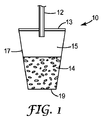
本明細書で開示する容器10は、円錐形、正方形、長方形など、いかなる形状をなしてもよい。図1に示す実施形態など、いくつかの実施形態において、本明細書で開示する容器10は、切頭円錐形の形状をなす側壁17と、底部19と、カバー13とを有している。側壁17は一般に、空気及び水に対して不浸透性である任意の材料を備える。例えば、高分子フィルム材料、アルミニウムシート材料などがカバーとして使用されてもよい。容器は、(注型、射出成形、押出しなどされた)プラスチック材料を含む任意の好適な材料から作製されてよい。任意選択により、任意の様式の食品用コーティングが、中に収容された食物成分14と接触する側壁の表面に使用されてよい。
The
カバー13は、容器10の用途に応じて様々な形態にて選択及び構成され得る。例えば、いくつかの実施形態において、カバーは、カバーに穴開けするのに必要な力の大きさを制御するために、特定の厚さをなしてよい。いくつかの実施形態において、カバー13は、カバー13の形状をある所望の大きさまで変形させるのに必要な流体力の大きさを制御するために、特定の厚さをなしてよい。いくつかの実施形態において、カバー13は、500マイクロメートル以下であっても、400マイクロメートル以下であっても、300マイクロメートル以下であっても、200マイクロメートル以下であっても、175マイクロメートル以下であっても、150マイクロメートル以下であっても、124マイクロメートル以下であっても、更には100マイクロメートル以下であってもよい。また、カバー13の外表面は、何らかの印刷された情報及び/又は絵画を含んでいてもよい。印刷された情報は例えば、指示であっても企業ブランドであってもよい。同様に、絵画は、飲用液を作る方法の絵画であっても企業ブランドであってもよい。
The
いくつかの実施形態において、カバー13は、少なくとも1枚のエラストマー層を備える。本開示において有用なエラストマー材料は、少なくとも中程度の弾性変形が可能である任意の材料である。本開示において有用なエラストマー材料は、カバー13のいかなる穿孔もそのような穿孔を生じさせるために使用された任意の装置の周りをシールするように選択される。
In some embodiments, the
本開示において有用なエラストマー材料はまた、カバー13のいかなる穿孔もそのような穿孔を生じさせるために使用された任意の装置を取除く際に再シールされるように選択される。本明細書において有用なエラストマー材料には、シリコーンゴム、合成ゴム、フルオロポリマーゴムなどが挙げられる。他のエラストマー材料には、A−B又はA−B−Aブロック共重合体として当業者に知られるものなど、エラストマーである天然又は合成ゴム共重合体が挙げられる。場合によっては有用となる他のエラストマー材料には、例えば、スチレン/イソプレン/スチレン(SIS)ブロック共重合体、弾性ポリウレタン、エチレン酢酸ビニルなどのエチレン共重合体、エチレン/プロピレン/ジエン三元重合体エラストマーのエチレン/プロピレンモノマー共重合体エラストマー、ポリエステルエラストマーが挙げられる。例示的な1つのエラストマーが、米国テキサス州ヒューストンのクレイトン・パフォーマンス・ポリマーズ社(Kraton Performance Polymers Inc.)から「クレイトン(KRATON)」の商標表記で販売されている合成ゴムである。これらの材料は、天然ゴムの多数の性質、例えば柔軟性とシール性をもたらすが、それに加えて、より高い耐熱性と耐薬品性を有する。これらの合成ゴムの化学的性質は、ポリスチレンブロック及びゴムブロックからなるスチレンブロック共重合体に基づき得る。ゴムブロックは通常、ポリブタジエン、ポリイソプレン又はそれらの水素化した等価物を含む。通常、これらの合成ゴム重合体は、その性質を最適化するために、ポリオレフィン、ポリスチレン、粘着付与樹脂又はパラフィン系オイルなどの他の材料を配合される。また、これらのエラストマーの熱的性質を改善するために、末端ブロック改質剤(End block modifiers)が加えられてもよい。
The elastomeric material useful in the present disclosure is also selected so that any perforations in the
本開示はまた、ゲルエラストマー、アクリルエラストマー、ポリエステルエラストマー及びポリウレタンエラストマーなど、他の種類のエラストマーを含む。これらの材料及び/又は商品名の例には、粘着付与SIS、n−ブチルアクリレート−メチルメタクリレート共重合体、熱可塑性ポリエステルエラストマー(デラウェア州ウィルミントンのイー・アイ・デュポン・ドゥ・ヌムール・アンド・カンパニー社(E.I. du Pont de Nemours and Company)から「ハイトレル(HYTREL)」の商標表記で商業的に入手可能なもの)、及び、テキサス州ウッドランズのハンツマン・コーポレーション社(Huntsman Corporation)から「IROGRAN」の商標表記で商業的に入手可能な熱可塑性ウレタンが挙げられる。理論に束縛されるものではないが、ゲルエラストマーは穴開けの後により速い流速を示し、したがって穿孔が密封され得る速度を向上し得る。また、エラストマー又は結果として得られるカバー(13)を電子ビームに暴露することも本開示の範囲に含まれる。理論に束縛されるものではないが、電子ビーム処理はエラストマーの架橋密度を更に向上させ得ると考えられる。また、エラストマー層は天然ゴムであってもよく、その天然ゴムは架橋結合部を含んでもよく、あるいは含まなくてもよい。 The present disclosure also includes other types of elastomers such as gel elastomers, acrylic elastomers, polyester elastomers and polyurethane elastomers. Examples of these materials and / or trade names include tackified SIS, n-butyl acrylate-methyl methacrylate copolymer, thermoplastic polyester elastomer (E.I. Dupont de Nemours & Co., Wilmington, Del.). Commercially available under the trademark “HYTREL” from EI du Pont de Nemours and Company) and “IROGRAN” from Huntsman Corporation of Woodlands, Texas And commercially available thermoplastic urethanes. Without being bound by theory, gel elastomers may exhibit a faster flow rate after drilling, thus improving the rate at which the perforations can be sealed. It is also within the scope of the present disclosure to expose the elastomer or resulting cover (13) to an electron beam. Without being bound by theory, it is believed that electron beam treatment can further improve the crosslink density of the elastomer. Further, the elastomer layer may be natural rubber, and the natural rubber may or may not include a cross-linked portion.
これらの種類又は特定のエラストマーのうちのいずれかの互いとの、あるいは改質用の非エラストマーとの配合もまた企図される。通常の充填剤、可塑剤、剛化補助剤、染料、顔料、プロセシング添加剤などをエラストマー層に組み込むことも本発明の範囲内に含まれる。いくつかの実施形態において、カバー13は更に、例えば、アルミニウム蒸着コーティング、ポリ塩化ビニリデン(PVDC)、エチレンビニルアルコール共重合体(EVOH)などの酸素バリアを含む。
Combinations of either of these types or specific elastomers with each other or with non-elastomers for modification are also contemplated. It is within the scope of the present invention to incorporate conventional fillers, plasticizers, stiffening aids, dyes, pigments, processing additives and the like into the elastomer layer. In some embodiments, the
いくつかの実施形態において、エラストマー層はまた、1種類の粘着付与剤又は粘着付与剤の組合わせを含む。理論に束縛されることを望むものではないが、粘着付与剤は、エラストマー層におけるエラストマー材料の流動性を高めて穿孔の再シール性を与え得る。典型的な粘着付与剤の例には、テキサス州ヒューストンのエクソンモービル・ケミカル・カンパニー社(ExxonMobil Chemical Company)から「ESCOREX 2203」の商標表記で商業的に入手可能なものが挙げられる。商業的に入手可能な粘着付与剤の例には、エクソンモービル・ケミカル・カンパニー社から「ESCOREZ」の商標表記で商業的に入手可能なものがある。 In some embodiments, the elastomeric layer also includes a single tackifier or combination of tackifiers. While not wishing to be bound by theory, tackifiers can increase the fluidity of the elastomeric material in the elastomeric layer and provide resealability of the perforations. Examples of typical tackifiers include those commercially available under the trademark designation “ESCOREX 2203” from ExxonMobil Chemical Company of Houston, Texas. An example of a commercially available tackifier is commercially available from ExxonMobil Chemical Company under the trademark designation “ESCOREZ”.
いくつかの実施形態において、カバー13は透明である。いくつかの実施形態において、カバー13は、例えば、特定の色又はパターンを中に有するなど、透明ではない。
In some embodiments, the
いくつかの実施形態において、カバー13は、側壁17と同じ材料を含む。底部19は、容器10が作製される用途に応じて、側壁17か又はカバー13と同じ材料から構成され得る。カバー13及び/又は底部19は、側壁17に一体的にあるいは操作可能に取り付けられる。操作可能に取り付ける例には、ヒートシールすること、音波溶接すること、接着剤によって取り付けること、機械的に取り付けることなどが挙げられる。接着剤で取り付けることに関して言えば、接着剤は、感圧性接着剤、硬化性ホットメルト接着剤、熱可塑性樹脂系接着剤、架橋重合体などであってもよい。機械的に取り付けることに関して言えば、カバー13は、クランプシーリング又はリングシーリング機構を利用して側壁17に取り付けられ、それによって容器10の外縁部をシールすることができ、容器10の外縁部においてカバー13は、クランプリングの下方でガスケットを使用するのと同様に、圧力シールを形成し得る。
In some embodiments, the
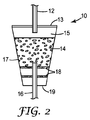
液体を受容するための容量15が設けられている一方で、食物成分14が容器10の一部分に収容されている。食物成分14は、液体であっても、固体であっても、それらの混合物であってもよい。液体を容器10の中及び/又は外に移動させるために、液体移送装置12がカバー13に挿入されてもよい。液体移送装置12は、針様の形態、チューブ、パイプ、又は同様のものを有する装置など、液体を送達することが可能な任意の装置であってよい。いくつかの実施形態において、液体移送装置12は、カバー13の穴開けを容易にするために、カバー13に穿孔する端部を先鋭化される。いくつかの実施形態において、カバー13は、液体移送装置12を受容するために、刻みを付けられるか、くぼみを付けられるか、あるいは機械的に改められる。
A
いくつかの実施形態において、容器10は、複数の液体移送装置によって、複数の箇所で穿孔されてもよい。例えば、図2において、第2の液体移送装置16が容器10の底部19に穿孔しているところが示されている。当業者には理解され得ることとして、液体移送装置12、16は、容器10の中及び外への液体の流れを容易にし得る。いくつかの実施形態において、食物成分14と底部19との間にフィルター材料18を設けることが望ましい。フィルター材料18は、紙、金属、合成物、及び同等のものを含む、任意の種類の織布若しくは不織布又は連続気泡発泡体のフィルター材料を含む。いくつかの実施形態において、フィルター材料18は、カバー13として選択された材料と類似した材料を含むバリアであってもよい。例えば、バリアは、カバー13に関連して開示したものと類似した、少なくとも1枚のエラストマー層を備えてもよい。
In some embodiments, the
いくつかの実施形態において、容器が、複数の液体移送装置によって概ね同じ箇所に穿孔されてもよい。例えば、図3において、第2の液体移送装置16と第3の液体移送装置20が共に容器10の底部19に穿孔しているところが示されている。当業者には理解され得ることとして、容器10が使用されている用途によっては、複数の箇所で容器10に穿孔するために、複数の液体移送装置が使用されてもよい。
In some embodiments, the container may be drilled at approximately the same location by multiple liquid transfer devices. For example, FIG. 3 shows that the second
いくつかの実施形態において、カバー13は、容器10内に設けられた液体食物成分又は液体食品の機械的な排出をもたらすように、エラストマー的に変形可能である。図4及び5に示すように、液外が、少なくとも1つの液体移送装置(図示のような第2の液体移送装置16など)を介して容器の中に注入され得る。当業者には理解され得ることとして、容器10の複数の箇所にて容器10に穿孔するために複数の液体移送装置が使用され得る。液体の注入は、液体食物成分のパッケージングの間、及び/又は液体食品の調製の間に行われ得る。いくつかの実施形態において、容器10は、任意選択によって、任意の種類の分離層を利用して、液体又は液体食物成分を受容する容量15から分離され得る食物成分14を有する。いくつかの実施形態において、食物成分14の容量15からの分離は、上部フィルター21を使用することによってもたらされる。任意選択により、フィルター材料18が食物成分14と底部19との間に使用され得る。上部フィルター19及びフィルター材料18は、紙、金属、合成物、及び同等のものを含む、任意の種類の織布若しくは不織布又は連続気泡発泡体のフィルター材料を含む。
In some embodiments, the
図6〜8は、側壁17とカバー13と底部19とを有する、本明細書で開示する容器10の別の実施形態の様々な位置を示しており、この側壁17、カバー13、及び底部19は、同じ材料を含んでも、異なる材料を含んでもよい。図6〜8において、容器10は、プランジャ26に操作可能に連結されたばね24を有しており、プランジャ26は、食物成分14と接触するか、あるいは食物成分14と隣接する。ばね24は、容器10内の食物成分、液体及び/又は流体食物成分の容量に応じて、伸張又は収縮され得る。いくつかの実施形態において、図7に示すように、ばね24は、少なくとも1つの液体移送装置16を通じて液体が注入されるとき、収縮位置にあり得る。ばね24は、一定の圧力量が液体に及ぼされる間、この収縮位置を維持し得る。ばね24及びプランジャ26は次いで、液体食物成分、液体及び/又は流体食品が容器10から吐出されるように、図8に示すように、ばねの再伸張によって機械的力を与えることができる。任意選択により、フィルター材料18は、食物成分14と底部19との間に使用され得る。当業者には理解され得ることとして、容器10の複数の箇所にて容器10に穿孔するために複数の液体移送装置が使用され得る。液体の注入は、液体食物成分のパッケージングの間、及び/又は液体食品の調製の間に行われ得る。
6-8 illustrate various positions of another embodiment of the
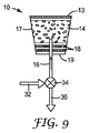
いくつかの実施形態において、容器10は、図9〜11に示すものなどの液体供給部32に操作可能に連結されてもよい。例示的な実施形態において、液体供給部32は、少なくとも1つの液体移送装置16を介して液体を容器10に入れるのに有用な方向制御弁34に液体を与える。制御弁34はまた、液体が容器10の中に流入するのを防止するためにも有用となり得る。制御弁34はまた、放出部36を介して液体、液体食品及び/又は流体食物成分を容器10から流出させるためにも有用となり得る。例えば、図9において、容器10は側壁17と、底部19と、カバー13とを有している。カバー13は、カバー13が弾性的に変形可能となるように、少なくとも1枚のエラストマー層を備えている。容器10はまた、食物成分14を収容している。容器10はまた、任意選択により、食物成分14と底部19との間にフィルター材料18を有してもよい。図9に示すように、方向制御弁34は「閉鎖」位置にあり、つまり、液体は、少なくとも1つの液体移送装置16を介して液体供給部32から容器10に流動することができない。
In some embodiments, the
図10は、方向制御弁34が「充填」位置にあり、少なくとも1つの液体移送装置16を介して液体を液体供給部32から容器10に流動させる実施形態を示している。カバー13は、容器10内の液体の体積が増加すると変形する。
FIG. 10 illustrates an embodiment in which the
図11は、方向制御弁34が「放出」位置にあり、少なくとも1つの液体移送装置16を介し、放出部36を通じて液体を容器10から流出させる一方で、更なる液体が液体供給部32から容器10に流入するのを防止する実施形態を示している。図11に従う実施形態は、カバー13がその元の形状を回復させるとき、容器10に収容された液体食物成分又は流体食品を少なくともある程度、機械的に排出するものである。図9〜11に示すように、液体が少なくとも1つの液体移送装置(図示のような第2の液体移送装置16など)を介して容器の中に注入され得る。当業者には理解され得ることとして、容器10の複数の箇所にて容器10に穿孔するために複数の液体移送装置が使用され得る。液体の注入は、液体食物成分のパッケージングの間、及び/又は液体食品の調製の間に行われ得る。
FIG. 11 shows that the
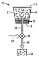
いくつかの実施形態において、容器10は、図12〜14に示すものなどの液体供給部32に操作可能に連結されてもよい。例示的な実施形態において、液体供給部32は、少なくとも1つの液体移送装置16を介して液体を容器10に入れるのに有用な方向制御弁34に液体を与える。制御弁34はまた、液体が容器10の中に流入するのを防止するためにも有用となり得る。制御弁34はまた、液体、液体食品及び/又は流体食物成分を、放出部36を介して容器10から流出させるためにも有用となり得る。図12において、容器10は、プランジャ26に操作可能に連結されたばね24を有しており、プランジャ26は、食物成分14と接触するか、あるいは隣接する。容器10はまた、任意選択により、食物成分14と底部19との間にフィルター材料18を有してもよい。図9に示すように、方向制御弁34は「閉鎖」位置にあり、つまり、液体は、少なくとも1つの液体移送装置16を介して液体供給部32から容器10に流動することができない。プランジャ26は依然として中立状態にあり、ばね24を依然として伸張位置に維持している。
In some embodiments, the
図13は、方向制御弁34が「充填」位置にあり、少なくとも1つの液体移送装置16を介して液体を液体供給部32から容器10に流動させる実施形態を示している。液体が容器10の中に流入するとき、プランジャ26がカバー13に向かって付勢され、ばね24を収縮位置へ移動させる。
FIG. 13 shows an embodiment in which the
図14は、方向制御弁34が「放出」位置にあり、少なくとも1つの液体移送装置16を介し、放出部36を通じて液体を容器10から流出させる一方で、更なる液体が液体供給部32から容器10に流入するのを防止する実施形態を示している。図11に従う実施形態は、ばね24が伸張位置へ移動し、プランジャ26がその元の中立位置を回復させるとき、容器10に収容された液体食物成分又は流体食品を少なくともある程度、機械的に排出するものである。図12〜14に示すように、液体が少なくとも1つの液体移送装置(図示のような第2の液体移送装置16など)を介して容器の中に注入され得る。当業者には理解され得ることとして、容器10の複数の箇所にて容器10に穿孔するために複数の液体移送装置が使用され得る。液体の注入は、液体食物成分のパッケージングの間、及び/又は液体食品の調製の間に行われ得る。
FIG. 14 shows that the
食物成分は任意の望ましい可食成分であってよい。いくつかの例として、挽いた焙煎コーヒー、茶、インスタントコーヒー、挽いたコーヒーとインスタントコーヒーとの混合物、チョコレートをベースにした製品、粉ミルクをベースにした製品、又は他の任意の脱水可食材料が挙げられ、知られている。食物成分はまた、水、フルーツジュース、野菜ジュースを含んだ液体であっても、風味付けされた液体であっても、飲料、炭酸飲料(アルコール及び非アルコールタイプの両方を含む)を含んだアルコールであってもよい。いくつかの実施形態において、食物成分と接触する液体は、温度において、約0℃〜約100℃、典型的には約50℃〜約90℃の範囲に及び得る。容器の中に注入される液体は、水(脱イオン水、水道水、蒸留水、炭酸水などを含む)であっても、牛乳(乳脂、全乳、2%の牛乳、1%の牛乳、脱脂乳などを含む)であっても、任意の他の好適な液体であってもよい。 The food ingredient may be any desirable edible ingredient. Some examples include ground roasted coffee, tea, instant coffee, a mixture of ground coffee and instant coffee, a chocolate based product, a powdered milk based product, or any other dehydrated edible material And are known. Food ingredients can also be liquids containing water, fruit juices, vegetable juices or flavored liquids, including beverages, carbonated drinks (including both alcoholic and non-alcoholic types) It may be. In some embodiments, the liquid in contact with the food ingredient can range in temperature from about 0 ° C. to about 100 ° C., typically from about 50 ° C. to about 90 ° C. Even if the liquid injected into the container is water (including deionized water, tap water, distilled water, carbonated water, etc.), milk (milk fat, whole milk, 2% milk, 1% milk, Or non-fat milk etc.) or any other suitable liquid.
本明細書で開示するカバー13は、エラストマー層に加えて各層を備えてもよい。例えば、非エラストマー層が、エラストマー層の上又は下に含められてもよい。それに代わって、エラストマー層は、2枚の他の非エラストマー高分子層の間に挟まれてもよい。そのような構造において、所望の程度の穴開け耐性並びにシール及び再シールする能力が、フィルムの性質を調節することによって左右され得る。プラスチック材料の例には、ポリエチレン、ポリプロピレン、ポリメチルメタクリレート、ポリエチレンテレフタレート、ポリアミド、エチレンビニルアルコール、及びそれらの組み合わせなどの熱可塑性樹脂が挙げられる。熱硬化性樹脂の例には、ビスフェノールAエポキシのジグリシジルエステル樹脂、ビスフェノールAジシアネートエステル、オルトフタル酸系不飽和ポリエステル、ビスフェノールAビニルエステルなどが挙げられる。3枚の層を有するカバー構造の例が、ポリプロピレン、合成ゴムエラストマー及びポリエチレンである。それに代わって、ある構造が、ポリオレフィン、合成ゴムエラストマー、及びポリエステルの3層を有してもよい。いくつかの実施形態において、ある3層構造が、ポリオレフィン、合成ゴムエラストマー、及び接着フィルム層を有する。接着層はまた、カバーを容器に接合してもよい。場合により、これらの例における合成ゴムエラストマーは、シリコーンエラストマーと置き換えられてもよい。これらの3層はそれぞれ、厚さにおいて20マイクロメートル〜500マイクロメートルの範囲に及ぶ。蒸着するバリアコーティングをある表面の全体に施すことも本発明の範囲に含まれる。
The
本開示において有用な多層フィルムは、コーティング、積層、共押出し、段階押出し(stepwise extruding)、キャストフィルム、インフレーションフィルムなど、任意の通常の技術で形成され得る。共押出しプロセスの例が、米国特許第3,557,265号及び同第3,479,425号に見出され得る。各層は通常、フィルムを形成する間に様々な材料を接触させる専用のフィードブロック又は専用のダイを通じて共押出しされる。エラストマーフィルムと非エラストマーフィルムの交互層が利用されてもよい。本開示において有用なフィルムは、3層〜10層などの、3層〜100層からならどの範囲でも異なるフィルムの組み合わせを有し得る。いくつかの実施形態において、多層フィルムは、間にエラストマーフィルム層を有する2枚のポリオレフィン層を備える。加えて、エラストマーフィルム層と非エラストマーフィルム層は、同じ厚さをなしても、異なる厚さをなしてもよい。カバーは継続的に製造され、次いで所望の形状及び寸法の最終的な所望のカバーに変換され得る。この変換は、打抜き、回転打抜き、レーザー切断、ウォータージェット切断などを含む任意の通常の方法を利用して達成され得る。加工条件は、所望の高分子特性を達成するように最適化される。これらの加工条件は、冷却及び/又は急冷温度を含む。 Multilayer films useful in the present disclosure can be formed by any conventional technique such as coating, lamination, coextrusion, stepwise extruding, cast film, blown film, and the like. Examples of coextrusion processes can be found in US Pat. Nos. 3,557,265 and 3,479,425. Each layer is typically coextruded through a dedicated feedblock or a dedicated die that contacts the various materials during film formation. Alternate layers of elastomeric and non-elastomeric films may be utilized. Films useful in the present disclosure may have different film combinations in any range from 3 to 100 layers, such as 3 to 10 layers. In some embodiments, the multilayer film comprises two polyolefin layers with an elastomeric film layer in between. In addition, the elastomeric film layer and the non-elastomeric film layer may have the same thickness or different thicknesses. The cover can be manufactured continuously and then converted into a final desired cover of the desired shape and dimensions. This conversion can be accomplished utilizing any conventional method including punching, rotary punching, laser cutting, water jet cutting, and the like. Processing conditions are optimized to achieve the desired polymer properties. These processing conditions include cooling and / or quenching temperatures.
いかなる理論にも束縛されることを望むものではないが、再シールするためには、エラストマーは穴開け後に自在に流動する必要がある。エラストマー層内のエラストマー材料が、過度に強固に保持されるか、あるいはフィルム構造内に拘束される場合、エラストマー材料は効果的に流動できず、したがって、再シールの速度が、いくつかの実施形態においては遅すぎて有効とならなくなる。この再シール特性を向上させるように、本明細書で開示したカバーを定式化する多数の方式が存在する。 While not wishing to be bound by any theory, in order to reseal, the elastomer must flow freely after drilling. If the elastomeric material in the elastomeric layer is held too tightly or constrained within the film structure, the elastomeric material cannot flow effectively and thus the speed of resealing may be reduced in some embodiments. Is too late to be effective. There are numerous ways to formulate the cover disclosed herein to improve this reseal property.
いくつかの実施形態において、多孔質材料が、エラストマー層の上部又は下部に置かれてもよい。典型的な多孔質材料の例には、スクリム、格子、スクリーン、発泡基板、不織布、パターン化基板などが挙げられる。多孔質材料の多孔度の大きさは、カバーに応じて最適化され得る。理論に束縛されるものではないが、エラストマー層内のエラストマー材料は、穿孔の再シールをもたらすように多孔質材料を通じて流動し得ると考えられる。同様に、多孔質材料は、カバー内のスペーサを設けるか、あるいはカバー内のスペーサとして働く。 In some embodiments, the porous material may be placed on top or bottom of the elastomeric layer. Examples of typical porous materials include scrims, lattices, screens, foam substrates, nonwovens, patterned substrates, and the like. The degree of porosity of the porous material can be optimized depending on the cover. Without being bound by theory, it is believed that the elastomeric material in the elastomeric layer can flow through the porous material to provide reseal of the perforations. Similarly, the porous material provides a spacer in the cover or acts as a spacer in the cover.
いくつかの実施形態において、再シールは、カバー自体に多孔性を与えることによって達成され得る。このことは、発泡技術、又は加工中にカバー内の各層のいずれかにガスを注入することなど、様々な技術によって達成され得る。いくつかの実施形態において、加工中、エラストマー層は、エラストマー層自体とその上又は下の層との間に多孔性又は空隙を有するように加えられる。例えば押出しの間、エラストマー層は、上部の蓋に不均一に加えられ、気泡又は空隙を生じる。 In some embodiments, resealing can be accomplished by imparting porosity to the cover itself. This can be accomplished by various techniques such as foaming techniques or injecting gas into any of the layers in the cover during processing. In some embodiments, during processing, the elastomeric layer is added to have porosity or voids between the elastomeric layer itself and the layers above or below it. For example, during extrusion, the elastomer layer is applied unevenly to the top lid, creating bubbles or voids.
いくつかの実施形態において、発泡性の微小球など、発泡性材料が使用され得る。発泡性の微小球には、ジョージア州ダルスのエカケミカルス社(Eka Chemicals Inc.)から「EXPANCEL」の商標表記で商業的に入手可能なものが挙げられる。発泡性の微小球を使用して作製された、ある例示的なカバーが、2層以上の多層フィルム構造を有し、その多層フィルム構造において、1枚の層又は複数の層が添加剤/充填剤を含み、その添加剤/充填剤は、発泡性の微小球などの膨張剤であってよい。この多層フィルムは、感圧性接着剤を使用することによって、カバーの頂面に接着されることができ、その感圧性接着剤は、多層フィルムの2つの外層のうちの一方にコーティングされる。いくつかの実施形態において、この多層フィルムは、本明細書で開示するカプセルカバーの頂部(領域)の一部分のみを被覆する多層フィルムパッチである。いくつかの実施形態において、この多層フィルムは、先に開示したカバーフィルムに積層され、そのカバーフィルムは、本明細書で開示するカプセルカバーの頂部(領域)全体を被覆する。 In some embodiments, foamable materials can be used, such as foamable microspheres. Effervescent microspheres include those commercially available under the trademark “EXPANCEL” from Eka Chemicals Inc. of Duluth, Ga. An exemplary cover made using expandable microspheres has a multilayer film structure with two or more layers, in which one or more layers are additive / filled. And the additive / filler may be a swelling agent such as foamable microspheres. The multilayer film can be adhered to the top surface of the cover by using a pressure sensitive adhesive, and the pressure sensitive adhesive is coated on one of the two outer layers of the multilayer film. In some embodiments, the multilayer film is a multilayer film patch that covers only a portion of the top (region) of the capsule cover disclosed herein. In some embodiments, the multilayer film is laminated to the previously disclosed cover film, which covers the entire top (area) of the capsule cover disclosed herein.
いくつかの実施形態において、エラストマー材料が流動できるようにするために、エラストマー層とその上及び/又は下の層との間に中間層が存在する。この中間層は、エラストマー層と中間層との間に弱い又は低い接着力が存在するように選択される。カバーに穿孔された後、エラストマー層と中間層との間の接着力が低いことにより、エラストマー層は中間層から分離することが可能となり、それによって、エラストマー層内のエラストマー材料は、再シールのために穿孔を通じて流動することが可能となる。例えば、スチレンブロック共重合体のコア(「SEBS」と呼ばれるスチレン−エチレン/ブチレン−スチレン)を有するポリプロピレンスキンのエラストマー層が、本開示において中間層として有用となり得るエチレン酢酸ビニル(EVA)フィルムに対して、低い接着力を有するように定式化され得る。 In some embodiments, an intermediate layer is present between the elastomeric layer and the upper and / or lower layers to allow the elastomeric material to flow. This intermediate layer is selected such that there is a weak or low adhesion between the elastomeric layer and the intermediate layer. After being pierced into the cover, the low adhesion between the elastomeric layer and the intermediate layer allows the elastomeric layer to be separated from the intermediate layer, so that the elastomeric material in the elastomeric layer is resealed. Therefore, it becomes possible to flow through the perforations. For example, an elastomeric layer of polypropylene skin having a styrene block copolymer core (styrene-ethylene / butylene-styrene called “SEBS”) may be useful as an intermediate layer in this disclosure for an ethylene vinyl acetate (EVA) film. And can be formulated to have low adhesion.
いくつかの実施形態において、本明細書で開示するカバーは、メッシュ層とエラストマー層との組み合わせを有し、そのエラストマー層は粘着付与剤を有する。理論に束縛されるものではないが、メッシュ層は、エラストマー層内の粘着性を付与されたエラストマー材料が流動し穿孔を再シールすることを可能にする空間を与えると考えられる。 In some embodiments, the cover disclosed herein has a combination of a mesh layer and an elastomer layer, the elastomer layer having a tackifier. Without being bound by theory, it is believed that the mesh layer provides a space that allows the tackified elastomeric material within the elastomer layer to flow and reseal the perforations.
いくつかの実施形態において、本明細書で開示するカバーは、エラストマー層の組合わせを有し、そのエラストマー層は、注入された液体の温度で軟化する接着剤で貼り付けられる。理論に束縛されるものではないが、エラストマー材料の拘束がゆるみ、したがって、液体移送装置の周りで収縮して穿孔を再シールすることが可能になると考えられる。 In some embodiments, the cover disclosed herein has a combination of elastomeric layers that are affixed with an adhesive that softens at the temperature of the injected liquid. Without being bound by theory, it is believed that the elastomeric material is loosened and thus can shrink around the liquid transfer device to re-seal the perforations.
本発明の様々な修正形態及び変更形態が、本発明の範疇及び趣旨から逸脱することなく、当業者には明らかとなろう。 Various modifications and alterations of this invention will become apparent to those skilled in the art without departing from the scope and spirit of this invention.
Claims (20)
(b)前記容器内に収容された食物成分であって、液体食物成分又は固体食物成分であり、更には、前記固体食物成分は、液体と接触すると流体食品を生じるように構成されている食物成分とを備え、
前記カバーは、前記液体食物成分又は前記流体食品を注入又は抽出するための少なくとも1つの液体移送装置によって穴開けされるように構成されており、更には、前記少なくとも1つの液体移送装置が前記容器から取除かれると、前記カバーは、前記液体、液体食物成分、流体食品、又はそれらの組み合わせのいずれの漏れに対しても、カバー自体を再シールするように構成されている容器。 (A) a cover comprising at least one elastomer layer;
(B) a food component contained in the container, wherein the food component is a liquid food component or a solid food component, and the solid food component is configured to produce a fluid food when in contact with the liquid; With ingredients,
The cover is configured to be pierced by at least one liquid transfer device for injecting or extracting the liquid food component or the fluid food, and further, the at least one liquid transfer device is the container When removed from the container, the cover is configured to reseal the cover itself against leakage of any of the liquid, liquid food ingredients, fluid food, or combinations thereof.
(b)プランジャの第1の表面に操作可能に連結されたばねと、前記プランジャの第2の表面と接触する前記食物成分との間で前記容器内に移動可能に固定されたプランジャと、
(c)前記食物成分が収容されている前記容器の一部分に穴開けするように構成された少なくとも1つの液体移送装置とを備え、
前記ばねは、前記プランジャの前記第1の表面と、前記容器のうちの前記食物成分と接触しない部分の内側表面との間で付勢される容器。 (A) a food ingredient contained in the container, which is a liquid food ingredient or a solid food ingredient, and the solid food ingredient is configured to produce a fluid food when in contact with the liquid; Ingredients,
(B) a plunger operably coupled to the first surface of the plunger and a plunger movably secured within the container between the food component in contact with the second surface of the plunger;
(C) comprising at least one liquid transfer device configured to pierce a portion of the container in which the food ingredient is contained;
The spring is a container that is biased between the first surface of the plunger and an inner surface of a portion of the container that does not contact the food component.
Applications Claiming Priority (7)
| Application Number | Priority Date | Filing Date | Title |
|---|---|---|---|
| US201161509392P | 2011-07-19 | 2011-07-19 | |
| US61/509,392 | 2011-07-19 | ||
| US201161529446P | 2011-08-31 | 2011-08-31 | |
| US61/529,446 | 2011-08-31 | ||
| US201261608869P | 2012-03-09 | 2012-03-09 | |
| US61/608,869 | 2012-03-09 | ||
| PCT/US2012/047272 WO2013012971A2 (en) | 2011-07-19 | 2012-07-19 | Sealed container and methods of use therof |
Publications (2)
| Publication Number | Publication Date |
|---|---|
| JP2014527426A true JP2014527426A (en) | 2014-10-16 |
| JP2014527426A5 JP2014527426A5 (en) | 2015-09-10 |
Family
ID=47558714
Family Applications (1)
| Application Number | Title | Priority Date | Filing Date |
|---|---|---|---|
| JP2014521746A Pending JP2014527426A (en) | 2011-07-19 | 2012-07-19 | Seal container and method of using the seal container |
Country Status (6)
| Country | Link |
|---|---|
| US (1) | US20140220192A1 (en) |
| EP (1) | EP2734457A4 (en) |
| JP (1) | JP2014527426A (en) |
| CN (1) | CN103687794B (en) |
| BR (1) | BR112014001161A2 (en) |
| WO (1) | WO2013012971A2 (en) |
Cited By (1)
| Publication number | Priority date | Publication date | Assignee | Title |
|---|---|---|---|---|
| JP2016527946A (en) * | 2013-07-10 | 2016-09-15 | ネステク ソシエテ アノニム | Capsule for beverage preparation |
Families Citing this family (8)
| Publication number | Priority date | Publication date | Assignee | Title |
|---|---|---|---|---|
| AT514716B1 (en) * | 2013-09-02 | 2015-09-15 | Pro Aqua Diamantelektroden Produktion Gmbh & Co Kg | Disposable capsule and method of making a serving of beverage in a beverage vending machine |
| CA2945339C (en) * | 2013-12-16 | 2018-08-21 | 2266170 Ontario Inc. | Capsule with sensory attributes |
| CA2943295C (en) * | 2014-03-21 | 2022-06-28 | 2266170 Ontario Inc. | Capsule with steeping chamber |
| MX2017001938A (en) * | 2014-08-14 | 2017-06-21 | Nestec Sa | Pack for preparing infusion beverages. |
| BR112019008836A2 (en) | 2016-11-09 | 2019-07-09 | Pepsico Inc | carbonated beverage manufacturing sets, methods, and systems |
| CA3081772C (en) * | 2018-04-23 | 2020-10-20 | 2266170 Ontario Inc. | Capsules, beverage brewing systems and fabrics with optimum filtration characteristics |
| SG11202104934TA (en) * | 2018-12-04 | 2021-06-29 | Nestle Sa | A beverage pod |
| CN114789843B (en) * | 2022-04-24 | 2022-11-22 | 四川先通原子医药科技有限公司 | Container for radioactive particles and use thereof |
Citations (2)
| Publication number | Priority date | Publication date | Assignee | Title |
|---|---|---|---|---|
| WO2010066705A1 (en) * | 2008-12-09 | 2010-06-17 | Nestec S.A. | Capsule for preparing a beverage by centrifugation in a beverage preparation device and device adapted therefore |
| JP2010521263A (en) * | 2007-03-23 | 2010-06-24 | ネステク ソシエテ アノニム | Beverage material capsule with a perforated plate having a vacuum opening |
Family Cites Families (12)
| Publication number | Priority date | Publication date | Assignee | Title |
|---|---|---|---|---|
| JP2000262405A (en) * | 1999-03-18 | 2000-09-26 | Soc Prod Nestle Sa | Sealed cartridge for drink extraction |
| DE29917586U1 (en) * | 1999-10-06 | 2000-01-05 | Eugster Frismag Ag Romanshorn | Espresso machine with a brewing piston that can be moved in a brewing cylinder |
| PT1190959E (en) * | 2000-09-26 | 2004-06-30 | Nestle Sa | CLOSED PACKAGE FOR CONFECTIONING A DRINK INTENDED TO BE EXTRACTED UNDER PRESSURE |
| US20060280841A1 (en) * | 2000-12-22 | 2006-12-14 | Cai Edward Z | Drink cartridge and method of manufacturing the same |
| US20040256051A1 (en) * | 2003-06-13 | 2004-12-23 | Turvey Robert R. | Method of manufacturing container covers |
| EP1500357B1 (en) * | 2003-07-23 | 2006-02-22 | Monodor S.A. | Method for preparing a beverage from a capsule and apparatus adapted for performing such method |
| ES2313501T3 (en) * | 2006-06-06 | 2009-03-01 | Nestec S.A. | CAPSULE WITH REDUCED DRIP. |
| PL2141093T3 (en) * | 2006-08-04 | 2013-01-31 | Lavazza Luigi Spa | Sealed capsule for the preparation of a beverage, in particular espresso coffee |
| CN102238890B (en) * | 2008-12-03 | 2014-01-22 | 雀巢产品技术援助有限公司 | Capsule for the preparation of a beverage by centrifugation |
| EP2364930B1 (en) * | 2009-03-19 | 2018-12-05 | Nestec S.A. | Capsule for preparing coffee in a device comprising a cartridge holder with relief and recessed elements |
| AT508887B1 (en) * | 2009-09-28 | 2011-11-15 | Sunday Products Handels Gmbh & Co Kg | COFFEE CAPSULE |
| US8895090B2 (en) * | 2010-09-22 | 2014-11-25 | K-Fee System Gmbh | Portion capsule and method for producing the same |
-
2012
- 2012-07-19 WO PCT/US2012/047272 patent/WO2013012971A2/en active Application Filing
- 2012-07-19 EP EP20120814587 patent/EP2734457A4/en not_active Withdrawn
- 2012-07-19 JP JP2014521746A patent/JP2014527426A/en active Pending
- 2012-07-19 US US14/232,779 patent/US20140220192A1/en not_active Abandoned
- 2012-07-19 CN CN201280035365.7A patent/CN103687794B/en not_active Expired - Fee Related
- 2012-07-19 BR BR112014001161A patent/BR112014001161A2/en not_active IP Right Cessation
Patent Citations (2)
| Publication number | Priority date | Publication date | Assignee | Title |
|---|---|---|---|---|
| JP2010521263A (en) * | 2007-03-23 | 2010-06-24 | ネステク ソシエテ アノニム | Beverage material capsule with a perforated plate having a vacuum opening |
| WO2010066705A1 (en) * | 2008-12-09 | 2010-06-17 | Nestec S.A. | Capsule for preparing a beverage by centrifugation in a beverage preparation device and device adapted therefore |
Cited By (1)
| Publication number | Priority date | Publication date | Assignee | Title |
|---|---|---|---|---|
| JP2016527946A (en) * | 2013-07-10 | 2016-09-15 | ネステク ソシエテ アノニム | Capsule for beverage preparation |
Also Published As
| Publication number | Publication date |
|---|---|
| CN103687794A (en) | 2014-03-26 |
| WO2013012971A2 (en) | 2013-01-24 |
| EP2734457A4 (en) | 2015-04-22 |
| WO2013012971A3 (en) | 2013-05-02 |
| CN103687794B (en) | 2016-05-18 |
| EP2734457A2 (en) | 2014-05-28 |
| BR112014001161A2 (en) | 2017-02-21 |
| US20140220192A1 (en) | 2014-08-07 |
Similar Documents
| Publication | Publication Date | Title |
|---|---|---|
| JP2014527426A (en) | Seal container and method of using the seal container | |
| JP6014673B2 (en) | Capsules for use in beverage preparation machines | |
| JP6013494B2 (en) | Cartridges used for coffee and general soluble products | |
| JP6449931B2 (en) | Potion capsule and method for producing a beverage using the potion capsule | |
| AU2011361036B2 (en) | Capsule, device and method for preparing a beverage by extraction | |
| CN103732262B (en) | Device for evaporation of volatile substances | |
| JP5558565B2 (en) | System, method and capsule for preparing a beverage | |
| CN101869532B (en) | Peelable seal closure assembly | |
| JP2016524486A (en) | Beverage preparation system, capsule and method for producing a beverage | |
| JP2014505564A (en) | Beverage preparation container with improved pierceable foil and method for preparing a beverage | |
| RU2004124827A (en) | SEALED CAPSULE WITH OPENING | |
| JP2014511193A (en) | Capsules for preparing beverages by centrifugation and methods for preparing such capsules | |
| CN102803094A (en) | Heat and/or steam activated valve and method therefor | |
| CN109689533A (en) | It is used to prepare the capsule of infusion beverage and solvable beverage | |
| CN109195883B (en) | Capsule for making a beverage | |
| AU2006330753A1 (en) | Fluid-filled bag and overwrap assembly | |
| JP2019534213A (en) | Beverage preparation capsules | |
| EP3194301A1 (en) | Capsule for use with a beverage production machine | |
| JP2020510479A (en) | Beverage preparation capsule | |
| JP2005001744A (en) | Spout-having pouch | |
| JP2017071413A (en) | Pouring tool-attached bag, and package using the same | |
| JPH03285636A (en) | Package of seasoning for pickle | |
| AU2013267069A1 (en) | Fluid-filled bag and overwrap assembly |
Legal Events
| Date | Code | Title | Description |
|---|---|---|---|
| A521 | Written amendment |
Free format text: JAPANESE INTERMEDIATE CODE: A523 Effective date: 20150721 |
|
| A621 | Written request for application examination |
Free format text: JAPANESE INTERMEDIATE CODE: A621 Effective date: 20150721 |
|
| A977 | Report on retrieval |
Free format text: JAPANESE INTERMEDIATE CODE: A971007 Effective date: 20160523 |
|
| A131 | Notification of reasons for refusal |
Free format text: JAPANESE INTERMEDIATE CODE: A131 Effective date: 20160607 |
|
| A601 | Written request for extension of time |
Free format text: JAPANESE INTERMEDIATE CODE: A601 Effective date: 20160907 |
|
| A02 | Decision of refusal |
Free format text: JAPANESE INTERMEDIATE CODE: A02 Effective date: 20170214 |