JP2014526821A - Wireless communication system - Google Patents
Wireless communication system Download PDFInfo
- Publication number
- JP2014526821A JP2014526821A JP2014529069A JP2014529069A JP2014526821A JP 2014526821 A JP2014526821 A JP 2014526821A JP 2014529069 A JP2014529069 A JP 2014529069A JP 2014529069 A JP2014529069 A JP 2014529069A JP 2014526821 A JP2014526821 A JP 2014526821A
- Authority
- JP
- Japan
- Prior art keywords
- wireless
- receiver
- event data
- connection event
- transmitter
- Prior art date
- Legal status (The legal status is an assumption and is not a legal conclusion. Google has not performed a legal analysis and makes no representation as to the accuracy of the status listed.)
- Pending
Links
Images


Classifications
-
- H—ELECTRICITY
- H04—ELECTRIC COMMUNICATION TECHNIQUE
- H04W—WIRELESS COMMUNICATION NETWORKS
- H04W52/00—Power management, e.g. TPC [Transmission Power Control], power saving or power classes
- H04W52/02—Power saving arrangements
- H04W52/0209—Power saving arrangements in terminal devices
- H04W52/0212—Power saving arrangements in terminal devices managed by the network, e.g. network or access point is master and terminal is slave
- H04W52/0216—Power saving arrangements in terminal devices managed by the network, e.g. network or access point is master and terminal is slave using a pre-established activity schedule, e.g. traffic indication frame
-
- H—ELECTRICITY
- H04—ELECTRIC COMMUNICATION TECHNIQUE
- H04W—WIRELESS COMMUNICATION NETWORKS
- H04W52/00—Power management, e.g. TPC [Transmission Power Control], power saving or power classes
- H04W52/02—Power saving arrangements
- H04W52/0209—Power saving arrangements in terminal devices
- H04W52/0225—Power saving arrangements in terminal devices using monitoring of external events, e.g. the presence of a signal
- H04W52/0229—Power saving arrangements in terminal devices using monitoring of external events, e.g. the presence of a signal where the received signal is a wanted signal
-
- H—ELECTRICITY
- H04—ELECTRIC COMMUNICATION TECHNIQUE
- H04W—WIRELESS COMMUNICATION NETWORKS
- H04W52/00—Power management, e.g. TPC [Transmission Power Control], power saving or power classes
- H04W52/02—Power saving arrangements
- H04W52/0209—Power saving arrangements in terminal devices
- H04W52/0225—Power saving arrangements in terminal devices using monitoring of external events, e.g. the presence of a signal
- H04W52/0241—Power saving arrangements in terminal devices using monitoring of external events, e.g. the presence of a signal where no transmission is received, e.g. out of range of the transmitter
-
- H—ELECTRICITY
- H04—ELECTRIC COMMUNICATION TECHNIQUE
- H04W—WIRELESS COMMUNICATION NETWORKS
- H04W52/00—Power management, e.g. TPC [Transmission Power Control], power saving or power classes
- H04W52/02—Power saving arrangements
- H04W52/0209—Power saving arrangements in terminal devices
- H04W52/0261—Power saving arrangements in terminal devices managing power supply demand, e.g. depending on battery level
- H04W52/0274—Power saving arrangements in terminal devices managing power supply demand, e.g. depending on battery level by switching on or off the equipment or parts thereof
-
- H—ELECTRICITY
- H04—ELECTRIC COMMUNICATION TECHNIQUE
- H04W—WIRELESS COMMUNICATION NETWORKS
- H04W56/00—Synchronisation arrangements
- H04W56/001—Synchronization between nodes
- H04W56/0015—Synchronization between nodes one node acting as a reference for the others
-
- H—ELECTRICITY
- H04—ELECTRIC COMMUNICATION TECHNIQUE
- H04W—WIRELESS COMMUNICATION NETWORKS
- H04W56/00—Synchronisation arrangements
- H04W56/0055—Synchronisation arrangements determining timing error of reception due to propagation delay
- H04W56/0065—Synchronisation arrangements determining timing error of reception due to propagation delay using measurement of signal travel time
- H04W56/007—Open loop measurement
- H04W56/0075—Open loop measurement based on arrival time vs. expected arrival time
-
- H—ELECTRICITY
- H04—ELECTRIC COMMUNICATION TECHNIQUE
- H04W—WIRELESS COMMUNICATION NETWORKS
- H04W72/00—Local resource management
- H04W72/04—Wireless resource allocation
- H04W72/044—Wireless resource allocation based on the type of the allocated resource
- H04W72/0446—Resources in time domain, e.g. slots or frames
-
- Y—GENERAL TAGGING OF NEW TECHNOLOGICAL DEVELOPMENTS; GENERAL TAGGING OF CROSS-SECTIONAL TECHNOLOGIES SPANNING OVER SEVERAL SECTIONS OF THE IPC; TECHNICAL SUBJECTS COVERED BY FORMER USPC CROSS-REFERENCE ART COLLECTIONS [XRACs] AND DIGESTS
- Y02—TECHNOLOGIES OR APPLICATIONS FOR MITIGATION OR ADAPTATION AGAINST CLIMATE CHANGE
- Y02D—CLIMATE CHANGE MITIGATION TECHNOLOGIES IN INFORMATION AND COMMUNICATION TECHNOLOGIES [ICT], I.E. INFORMATION AND COMMUNICATION TECHNOLOGIES AIMING AT THE REDUCTION OF THEIR OWN ENERGY USE
- Y02D30/00—Reducing energy consumption in communication networks
- Y02D30/70—Reducing energy consumption in communication networks in wireless communication networks
Abstract
無線通信システムは、無線送信機(2)とその無線送信機から無線伝送を受信するように構成された無線受信機(12)とを備える。送信機(2)は、送信機クロック信号を用いて一連の接続イベントデータパケット(22a’、22b’、22c’)を所定のスケジュールに従って送信する。受信機(12)は、送信機(2)から連続した接続イベントデータパケットを受信する合間にスリープ状態に入り、その状態では、受信機が送信機からの無線伝送を受信して処理することはない。受信機は、受信機クロック信号を用いて、接続イベントデータパケットの一つ(22b’)を受信してから所定数の受信機クロックサイクルが経過したときを判断し、対応可能状態になる。この所定数の受信機クロックサイクルは、受信機(12)によって受信された接続イベントデータパケットのうち二つ(22a’、22b’)を受信する間に経過した受信機クロックサイクル(34a)の数から補正係数(38)を差し引いたものである。
【選択図】図3The wireless communication system includes a wireless transmitter (2) and a wireless receiver (12) configured to receive wireless transmissions from the wireless transmitter. The transmitter (2) transmits a series of connection event data packets (22a ′, 22b ′, 22c ′) according to a predetermined schedule using the transmitter clock signal. The receiver (12) enters a sleep state between receiving successive connection event data packets from the transmitter (2), in which the receiver receives and processes wireless transmissions from the transmitter. Absent. The receiver uses the receiver clock signal to determine when a predetermined number of receiver clock cycles have elapsed since the reception of one of the connection event data packets (22b ′), and becomes ready for handling. This predetermined number of receiver clock cycles is the number of receiver clock cycles (34a) that have elapsed while receiving two (22a ', 22b') of the connection event data packets received by the receiver (12). Is obtained by subtracting the correction coefficient (38).
[Selection] Figure 3
Description
本発明は、無線送信機及び無線受信機を含む無線通信システムに関する。 The present invention relates to a wireless communication system including a wireless transmitter and a wireless receiver.
無線温度センサや無線自転車速度計のようなある種の電池駆動式装置には、低消費電力化のために最適化された無線送信機および/または無線受信機が含まれる。それらが電力を節約する一つの方法は、より長い時間をかけてもっとゆっくりではなく、一気にデータを伝送(バースト伝送)することである。こうすることで、送信機および/または受信機は、データのバースト伝送の合間に低エネルギースリープ状態に入ることができ、その間は無線回路および処理ロジックの一部の電源を落とすことができる。送信機または受信機は、内部クロックを使用し、次のデータ伝送に間に合って起動するように配置すればよい。 Certain battery-powered devices, such as wireless temperature sensors and wireless bicycle speedometers, include wireless transmitters and / or wireless receivers that are optimized for low power consumption. One way they save power is to transmit data at a stretch (burst transmission) at a stretch rather than slower over a longer time. In this way, the transmitter and / or receiver can enter a low energy sleep state between burst transmissions of data, during which time some of the radio circuitry and processing logic can be powered down. The transmitter or receiver may be arranged to start in time for the next data transmission using the internal clock.
送信機と受信機がクロック同期している場合、それらは両方とも、各伝送にちょうど間に合うように起動すればよい。しかし、受信機のクロックが必ずしも送信機のクロックと同期していない場合は(例えば、一方が他方よりわずかに進んでいる場合は)、二つのクロックの間に不整合が生じてもよいように、受信機は、そうでない場合よりも早く起動させるように構成する必要がある。受信機が十分に早く送信機からの信号を受信開始しないと、送信の開始を逃してしまう恐れがある。 If the transmitter and receiver are clocked, they both need to be activated just in time for each transmission. However, if the receiver clock is not necessarily synchronized with the transmitter clock (eg if one is slightly ahead of the other), there may be a mismatch between the two clocks. The receiver needs to be configured to start up faster than otherwise. If the receiver does not start receiving a signal from the transmitter sufficiently early, the start of transmission may be missed.
非同期クロックの無線送信機と無線受信機を電力抑制しながら動作させるというようなアプローチの一つは、ブルートゥース低エネルギー(BLE)リンク層<ブルートゥースコア仕様バージョン4.0、第6巻、パートB、2010年6月30日公開‐http://www.bluetooth.org/Technical/Specifications/adopted.htm>に記載されている。
One approach to operating asynchronous clock radio transmitters and radio receivers with reduced power is the Bluetooth Low Energy (BLE) link layer <Bluetooth Score Specification Version 4.0,
そのようなアプローチでは、図2に例示したように、マスタ無線送信機(TX)は、データパケット22aを送信することによって、スレーブ無線受信機(RX)との接続イベントを開始する。マスタ機器は、連続する接続イベントの開始の間が一定間隔(connInterval)24a,24bの、連続する規則的間隔の接続イベント開始パケット22a,22b,22cを送信する。これらの間隔は、送信機器内のクロックを用いて測定される。
In such an approach, as illustrated in FIG. 2, the master radio transmitter (TX) initiates a connection event with the slave radio receiver (RX) by transmitting a
スレーブ受信機は、データパケットが交換されない、接続イベントの合間にはスリープ状態となってエネルギーを節約する。スレーブは、次の接続イベントの開始を受け取る予想時刻を、既知である、送信間の一定間隔に基づいて算出するための「基準点」として、接続イベント22a,22b,22cの開始時刻を使用する。これらの時刻は、内部クロックを用いて決定される。
The slave receiver goes to sleep between connection events where no data packets are exchanged to save energy. The slave uses the start time of the
図2において、受信機は、接続イベントの最初のデータパケット22bを受信した後に長さconnIntervalの間隔26bが経過したと判定すると、起動して、次の接続イベントの最初のデータパケット22cの予想到着時刻に先立つ一定の時間30前に、受信ウィンドウ28を開く。この受信ウィンドウ28は、スレーブクロックがマスタクロックよりも進んでいるかまたは遅れている可能性があるので、理想的に必要とされるよりも早めに開かれる。その分だけ早めに開く時間30(windowWidening)の量は、百万分率(ppm)で表された、(スリープ状態にある)マスタ装置の最悪ケースのクロック精度と(スリープ状態にある)スレーブ装置のクロック精度の和に、スレーブで受信された最後の基準点を受信してから経過した時間26bの量を乗じたものである。スレーブは、必要に応じて(すなわち、データパケットがまだ受信されていない場合)、到着予定時刻後に同量の時間32(windowWidening)分だけ受信ウィンドウ28を開き続けてもよい。従って、受信ウィンドウ28は、最大2×windowWideningの幅を有する可能性がある。
In FIG. 2, if the receiver determines that the
典型的な例では、マスタ装置のクロックは、±500ppmの最悪ケースの精度を有することが知られ、スレーブ装置のクロックは、±500ppmの精度を有することが知られている。規則的な接続間隔24a,24b,26a,26b(connInterval)を一秒間とするならば、受信ウィンドウ28は、最大2ミリ秒であると想定される。
In a typical example, the master device clock is known to have a worst case accuracy of ± 500 ppm and the slave device clock is known to have an accuracy of ± 500 ppm. If the
このアプローチは、受信機が受信ウィンドウ28のいずれかの側でスリープするようにすることで、受信機を常に稼動状態に置く場合と比較して大幅な省電力が行なえる。そうではあるが、本発明は、さらにより電力効率の良い無線受信機を提供することを目的とする。
This approach allows significant power savings by allowing the receiver to sleep on either side of the receive
第一の態様から見ると、本発明は、無線送信機と前記無線送信機から無線伝送を受信するように構成された無線受信機とを備える無線通信システムを提供するものであって、前記無線送信機は、送信機クロック信号を用いて一連の接続イベントデータパケットを所定のスケジュールに従って無線で送信するように構成され、前記無線受信機は、
前記無線送信機から連続した接続イベントデータパケットを受信する合間にスリープ状態に入り、そのスリープ状態では、前記無線受信機が前記無線送信機からの無線伝送を受信して処理することはないように構成され、かつ
受信機クロック信号を用いて、一つの前記接続イベントデータパケットを受信してから所定数の受信機クロックサイクルが経過したときを判断し、それに応えて、前記無線受信機が前記無線送信機からの無線伝送を受信して処理することができる対応可能状態になるように構成されるが、ここで前記所定数の受信機クロックサイクルは、前記無線受信機によって受信された二つの前記接続イベントデータパケットをそれぞれ受信する合間に受信機クロックサイクルが何回経過したかに依存する。
Viewed from a first aspect, the present invention provides a wireless communication system comprising a wireless transmitter and a wireless receiver configured to receive wireless transmission from the wireless transmitter, the wireless communication system comprising: The transmitter is configured to wirelessly transmit a series of connection event data packets according to a predetermined schedule using a transmitter clock signal, the wireless receiver comprising:
A sleep state is entered between successive reception of connection event data packets from the wireless transmitter so that the wireless receiver does not receive and process wireless transmissions from the wireless transmitter in that sleep state. A receiver clock signal is used to determine when a predetermined number of receiver clock cycles have elapsed since receiving one of the connection event data packets, and in response, the wireless receiver Configured to be ready to receive and process wireless transmissions from a transmitter, wherein the predetermined number of receiver clock cycles are two of the two received by the wireless receiver Depends on how many receiver clock cycles have elapsed between each connection event data packet reception.
別の態様から見ると、本発明は、無線送信機および無線受信機を作動させる方法を提供するものであって、この方法は、
前記無線送信機が、送信機クロック信号を用いて一連の接続イベントデータパケットを所定のスケジュールに従って無線で送信するステップと、
前記無線受信機が、前記無線送信機から連続した接続イベントデータパケットを受信する合間にスリープ状態に入り、そのスリープ状態では、前記無線受信機が前記無線送信機からの無線伝送を受信して処理することはないステップと、
前記無線受信機が、受信機クロック信号を用いて、一つの接続イベントデータパケットを受信してから所定数の受信機クロックサイクルが経過したときを判断し、それに応えて、前記無線受信機が前記無線送信機からの無線伝送を受信して処理することができる対応可能状態になることを含むが、ここで前記所定数の受信機クロックサイクルは、前記無線受信機によって受信された前記接続イベントデータパケットのうち二つをそれぞれ受信する合間に受信機クロックサイクルが何回経過したかに依存するステップと、を含む。
Viewed from another aspect, the present invention provides a method of operating a wireless transmitter and a wireless receiver, the method comprising:
The wireless transmitter wirelessly transmitting a series of connection event data packets using a transmitter clock signal according to a predetermined schedule;
The wireless receiver enters a sleep state between receiving successive connection event data packets from the wireless transmitter, in which the wireless receiver receives and processes wireless transmissions from the wireless transmitter. Steps that you never do,
The wireless receiver uses a receiver clock signal to determine when a predetermined number of receiver clock cycles have elapsed since receiving one connection event data packet, and in response, the wireless receiver Including being ready to receive and process wireless transmissions from a wireless transmitter, wherein the predetermined number of receiver clock cycles is the connection event data received by the wireless receiver Depending on how many receiver clock cycles have elapsed between receiving each of the two of the packets.
さらなる態様から見ると、本発明は、一連の接続イベントデータパケットを所定のスケジュールに従って無線で送信する無線送信機からの無線伝送を受信するのに適した無線受信機を提供するものであって、前記無線受信機は、
前記無線送信機から連続した接続イベントデータパケットを受信する合間にスリープ状態に入り、そのスリープ状態では、前記無線受信機が前記無線送信機からの無線伝送を受信して処理することはないように構成され、かつ
受信機クロック信号を用いて、一つの前記接続イベントデータパケットを受信してから所定数の受信機クロックサイクルが経過したときを判断し、それに応えて、前記無線受信機が前記無線送信機からの無線伝送を受信して処理することができる対応可能状態になるように構成されるが、ここで前記所定数の受信機クロックサイクルは、前記無線受信機によって受信された二つの前記接続イベントデータパケットをそれぞれ受信する合間に受信機クロックサイクルが何回経過したかに依存する。
Viewed from a further aspect, the present invention provides a wireless receiver suitable for receiving a wireless transmission from a wireless transmitter that wirelessly transmits a series of connection event data packets according to a predetermined schedule, The wireless receiver
A sleep state is entered between successive reception of connection event data packets from the wireless transmitter so that the wireless receiver does not receive and process wireless transmissions from the wireless transmitter in that sleep state. A receiver clock signal is used to determine when a predetermined number of receiver clock cycles have elapsed since receiving one of the connection event data packets, and in response, the wireless receiver Configured to be ready to receive and process wireless transmissions from a transmitter, wherein the predetermined number of receiver clock cycles are two of the two received by the wireless receiver Depends on how many receiver clock cycles have elapsed between each connection event data packet reception.
したがって、本発明によれば、無線受信機が接続イベントデータパケットの一つを受信してから、この受信機が対応可能状態になるまでの時間の長さは、以前に受信した接続イベントデータパケットの到着時刻に応じて調整することができることは、当業者であれば理解できるであろう。これらの到着時刻には、送信機のクロック周波数と受信機のクロック周波数の違いに関連する情報が含まれているため、当該無線受信機は、それらを用いて受信機のクロック信号と送信機のクロック信号との間で長い間に生じたずれを補正することができる。 Therefore, according to the present invention, the length of time from when the wireless receiver receives one of the connection event data packets to when the receiver becomes ready is determined by the connection event data packet previously received. Those skilled in the art will understand that the time can be adjusted according to the arrival time of Since these arrival times contain information related to the difference between the clock frequency of the transmitter and the clock frequency of the receiver, the wireless receiver uses them to determine the clock signal of the receiver and the transmitter's clock frequency. It is possible to correct a deviation that has occurred with the clock signal for a long time.
その結果、これによって、受信機は、そのような補正がなされなかった場合よりもはるかに短い長さの時間だけ対応可能状態であればよく、その理由は、次の接続イベントデータパケットの到着時刻に残っている不確かさとしては、電気的または磁気的な干渉に起因するもののような、すぐに変化するタイミング的なアーチファクトに限られるからである。具体的には、前述した従来技術のアプローチとは対照的に、受信ウィンドウには、長い間に、もしくは徐々に、クロック信号間の最悪ケースのずれが生じる余地がないからであり、その理由は、対応可能状態になる時間を変えることによってこのずれが補正されるからである。したがって、受信ウィンドウを大幅に短くすることができる。 As a result, this requires that the receiver be ready for a much shorter amount of time than if no such correction was made because the arrival time of the next connection event data packet This is because the remaining uncertainty is limited to quickly changing timing artifacts, such as those due to electrical or magnetic interference. Specifically, in contrast to the prior art approaches described above, the receive window has no room for long-term or gradual worst-case deviations between clock signals, because This is because this shift is corrected by changing the time in which the response is possible. Therefore, the reception window can be significantly shortened.
本発明の背後にある基本的な知見として、送信機と受信機のクロック信号における潜在的な誤差は、急速に変化する(短期的な)誤差と徐々に変化する(長期的な)誤差に分割されるということである。これら二種類の誤差を別々に処理することによって、より大きな電力効率を達成することができる。例えば、本発明を具現化する無線受信機を含む装置に(例えば、床に落とすなど)物理的な衝撃が発生した場合、この結果として、それ自体のクロック信号の出力周波数に即時的、短期的な変化がもたらされることがある。しかし、クロック周波数は、ショック後すぐに長期平均周波数に戻るであろう。電気的ノイズや周囲温度の急激な変化も、同様に短期的影響を及ぼすことがある。このような影響は、それを容易に予測することはできず、このような誤差が発生してもよいように十分に広い受信ウィンドウを有することが、最良の対策となる。 As a fundamental finding behind the present invention, the potential errors in the transmitter and receiver clock signals are divided into rapidly changing (short-term) errors and gradually changing (long-term) errors. It is to be done. By treating these two types of errors separately, greater power efficiency can be achieved. For example, if a physical shock occurs in a device including a wireless receiver embodying the present invention (eg, dropped on the floor), this results in immediate and short-term output frequency of its own clock signal. Changes may occur. However, the clock frequency will return to the long-term average frequency soon after the shock. Electrical noise and sudden changes in ambient temperature can have short-term effects as well. Such effects cannot be easily predicted, and it is best to have a reception window that is sufficiently wide so that such errors may occur.
対照的に、おそらく製造ばらつきに起因して、二台の水晶発振器の基本周波数間に違いがある場合は、それぞれの発振器に由来する二つのクロック信号は、互いに対して予測可能な状態でずれることを意味するといえる。相対的なタイミング誤差は、衝撃によるものと同じぐらい大きなものかもしれないが(例えば、20ppm)、その変化率は非常に低く、誤差が予測可能となる。水晶発振器の使用年数、および周囲温度の漸進的な変化のような他の要因もまた、比較的長い時間尺度で(例えば、秒もしくはミリ秒の単位ではなく、時間の単位で)、徐々に変化していくずれを引き起こすことがある。 In contrast, if there is a difference between the fundamental frequencies of two crystal oscillators, possibly due to manufacturing variability, the two clock signals from each oscillator will shift in a predictable manner relative to each other. Can be said to mean. Although the relative timing error may be as large as that due to shock (eg, 20 ppm), the rate of change is very low and the error is predictable. Other factors such as the age of the crystal oscillator and the gradual change in ambient temperature also change gradually over a relatively long time scale (eg, in units of time, not seconds or milliseconds). May cause a gap.
本目的のために、「徐々に変わる」もしくは「長期的な」誤差とは、急速に変わるもしくは短期的な誤差とは対照的に、連続するデータパケットの各合間には、その区間において、クロック信号が一ppm未満しか変化しない、何らかのクロック信号誤差であるとみなすことにする。間隔が不規則である場合には、最大間隔または中間値もしくは他の平均値による間隔をこの定義にあてはめてもよい。 For this purpose, a “gradually changing” or “long-term” error is in contrast to a rapidly changing or short-term error, between each successive data packet, in the interval Consider a clock signal error that changes the signal by less than 1 ppm. If the spacing is irregular, a maximum spacing or a median or other average spacing may be applied to this definition.
受信したデータパケットの到着時刻に関連する情報、例えば、直前に受信した二つの接続イベントパケットの間隔の大きさを使用してモデル化し、比較的安定した長期の誤差を補正することによって、本発明を具体化した受信機は、急速に変化する誤差に十分に対応することができるように受信可能状態になりさえすればよい。受信機は、それによって、受信可能状態で過ごすべき時間の量を減らし、スリープ状態の時間を増やすことができるので、エネルギーを節約することができる。 By using information related to the arrival time of the received data packet, for example, the size of the interval between the two connection event packets received immediately before, and correcting a relatively stable long-term error, the present invention It is only necessary that the receiver embodying the above is in a receivable state so that it can sufficiently cope with a rapidly changing error. The receiver can thereby save energy because it can reduce the amount of time to spend in the ready state and increase the sleep time.
二つの接続イベントデータパケットは、その受信機クロックサイクルの数がそれぞれのパケット受信に依存することになるが、受信した接続イベントデータパケットのどれであってもよい。しかしながら、好ましい実施形態では、それらは、連続して受信される接続イベントデータパケットである。特に、それらは、直前に受信した二つの接続イベントデータパケットであることが好ましい。このようにすれば、受信機が受信可能状態になるタイミングは、送信機による接続イベントデータパケットの伝送に関して、受信機が利用可能な最新の情報に基づくことができる。 The two connection event data packets may be any of the received connection event data packets, although the number of receiver clock cycles will depend on the reception of each packet. However, in a preferred embodiment, they are connection event data packets that are received sequentially. In particular, they are preferably the two connection event data packets received immediately before. In this way, the timing at which the receiver becomes ready for reception can be based on the latest information available to the receiver regarding the transmission of connection event data packets by the transmitter.
受信機は、メモリ(例えば、RAMまたはレジスタ)に格納された変数を、二つの接続イベントデータパケットをそれぞれ受信する間に経過した受信機クロックサイクルの数に関連する値で更新するように構成されるのが好ましい。この値は、クロックサイクル数であってもよい。この更新は、問題なく接続イベントデータパケットを受信し終わる毎に行われるのが好ましい。こうすれば、長期的なずれは、非常に少ないメモリ要件でモデル化することができ、すなわち、リソースが限られた無線受信機にとっては非常に望ましいことである。 The receiver is configured to update a variable stored in memory (eg, RAM or register) with a value related to the number of receiver clock cycles that have elapsed between receiving each of the two connection event data packets. It is preferable. This value may be the number of clock cycles. This update is preferably performed every time a connection event data packet is received without any problem. In this way, long-term deviations can be modeled with very low memory requirements, i.e., highly desirable for radio receivers with limited resources.
実施形態によっては、受信機クロックサイクルの所定数は、前記それぞれ受信する間に、すなわち二つの接続イベントパケットの合間に、経過した受信機クロックサイクル数の線形関数であってもよい。実施形態によっては、受信機クロックサイクル数は、前記それぞれ(またはそれらの複数かもしくはその一部分)受信する間に経過した受信機クロックサイクル数から補正係数を差し引いたものに等しくてもよい。すると、この補正係数によって、受信機が、次の接続イベントデータパケットの到着予定よりもどのぐらい早く受信ウィンドウを開けばよいのか効果的に決まる。補正係数は、最後の接続イベントデータパケットを受信してから経過した受信機クロックサイクル数と共に増えてもよく、すなわち、例えば、当該クロックサイクル数に基本値を乗じたものに等しくてもよい。こうすれば、仮に接続イベントデータパケットが一つ失われた場合に、受信機は、最後に接続イベントデータパケットを受信してからの時間に比べて短期的な複数の変動をそれぞれの長さに応じて補正するために、次の接続イベントデータパケットのための受信ウィンドウを拡大するであろう。 In some embodiments, the predetermined number of receiver clock cycles may be a linear function of the number of receiver clock cycles that have elapsed during each said reception, ie, between two connection event packets. In some embodiments, the number of receiver clock cycles may be equal to the number of receiver clock cycles that have elapsed during the respective reception (or a plurality or a portion thereof) minus a correction factor. This correction factor then effectively determines how soon the receiver should open the reception window before the next connection event data packet is scheduled to arrive. The correction factor may increase with the number of receiver clock cycles that have elapsed since the last connection event data packet was received, i.e., for example, equal to the number of clock cycles multiplied by a base value. In this way, if one connection event data packet is lost, the receiver will add multiple short-term variations to each length compared to the time since the last connection event data packet was received. To compensate accordingly, the receive window for the next connection event data packet will be expanded.
補正係数、または基本値は、特定の送信機とのすべての通信に対して、または送信機と接続している間は(ここで、「接続」とは、ブルートゥース低エネルギーリンク層に定義されているものであってもよい)、一定であってもよい。これは、送信機クロックと受信機クロックの既知の、または想定した短期誤差特性に関連付けされてもよい。あるいは、補正係数、または基本値は、変更されてもよく、すなわち、例えば、接続イベントデータパケットの予想受信時間と実受信時間との差分量のような、受信済み接続イベントデータパケットに関連するタイミング情報に応じて変更されてもよい。このようにして、短期的で急速に変化する誤差も受信機によってモデル化すれば、受信ウィンドウの継続時間をさらに削減できる可能性がある。いずれの場合も、無線受信機は、新たな通信セッションの最初の一つまたは二つの接続イベントデータパケットを受信するときは、その受信機が長期的なずれの補正を開始するための十分な情報を獲得するまで、相当広い受信ウィンドウを使用してもよい。 The correction factor, or base value, is defined for the Bluetooth low energy link layer for all communications with a particular transmitter or while connected to the transmitter (where “connection” May be constant). This may be related to the known or assumed short-term error characteristics of the transmitter and receiver clocks. Alternatively, the correction factor, or base value, may be changed, i.e. timing associated with a received connection event data packet, such as, for example, the amount of difference between the expected reception time and the actual reception time of the connection event data packet It may be changed according to information. In this way, if the short-term and rapidly changing errors are modeled by the receiver, the duration of the reception window may be further reduced. In either case, when the wireless receiver receives the first one or two connection event data packets of a new communication session, it has enough information for the receiver to start correcting the long-term deviation. A fairly wide reception window may be used until
受信機は、一定の補正係数の二倍に等しい、最大数の受信機クロックサイクルの間、受信可能状態に留まるように構成されてもよい。従って、各受信ウィンドウは、最大で補正係数の長さの二倍までとなることもある。受信機は、特定の基準が満たされる場合、例えば、受信ウィンドウの継続時間内に、データパケットが完全にまたは部分的に受信された場合、受信可能状態を早く終えるように構成してもよい。受信機は、一つの接続イベントデータパケットが受信ウィンドウの時間内に完全にまたは部分的に受信された場合、受信可能状態から通信状態に移ってもよい。受信機は、それが受信可能状態でも通信状態でもないときにはスリープ状態になるように構成してもよい。 The receiver may be configured to remain in a ready state for a maximum number of receiver clock cycles equal to twice a certain correction factor. Therefore, each reception window may be up to twice the length of the correction coefficient. The receiver may be configured to exit the ready state early if certain criteria are met, eg, if a data packet is received completely or partially within the duration of the receive window. The receiver may transition from the ready state to the communication state if one connection event data packet is received completely or partially within the time of the reception window. The receiver may be configured to enter a sleep state when it is not in a receivable state or in a communication state.
受信機のクロック信号は、受信機が、例えば外部発振器から受信してもよいし、または、受信機が、例えば水晶発振器や抵抗・コンデンサ発振器を用いて発生させてもよい。同様に、送信機のクロック信号は、送信機が(外から)受信してもよいし、送信機が(自ら)発生させてもよい。 The clock signal of the receiver may be received by the receiver from, for example, an external oscillator, or may be generated by the receiver using, for example, a crystal oscillator or a resistor / capacitor oscillator. Similarly, the transmitter clock signal may be received by the transmitter (from the outside) or may be generated by the transmitter (self).
受信機のクロック信号は、受信機がスリープ状態のときは受信可能状態または通信状態のときとは異なる特性を有していてもよい。具体的には、信号は、受信機がスリープ状態のときは第一クロック源から発生し、受信可能状態または通信状態のときは第二クロック源から発生してもよい。第一クロック源は、より低い電力しか消費しないかわりに、第二クロック源と比べて比較的精度が低くてもよい。例えば、第一クロック源は抵抗・コンデンサ発振器であり、一方、第二クロック源は水晶発振器であってもよい。 The clock signal of the receiver may have different characteristics when the receiver is in the sleep state than when it is in the reception enabled state or the communication state. Specifically, the signal may be generated from a first clock source when the receiver is in a sleep state, and may be generated from a second clock source when the receiver is in a receivable state or a communication state. The first clock source may consume less power but may be relatively less accurate than the second clock source. For example, the first clock source may be a resistor / capacitor oscillator, while the second clock source may be a crystal oscillator.
無線送信機は、定期的に一連の接続イベントデータパケットを送信するように構成されてもよい、すなわち、送信機は、接続イベントデータパケット間の間隔が一定数の送信機クロックサイクルであるように構成してもよい。しかし、より複雑な送信スケジュールが可能であり、例えば、可変数の送信機クロックサイクル後に接続イベントデータパケットを送信したり、あるいはスケジュールされた複数の接続イベントごとにデータパケットを体系的にスキップしたりしてもよい。 The wireless transmitter may be configured to periodically transmit a series of connection event data packets, i.e., the transmitter is such that the interval between connection event data packets is a fixed number of transmitter clock cycles. It may be configured. However, more complex transmission schedules are possible, such as sending connection event data packets after a variable number of transmitter clock cycles, or systematically skipping data packets for multiple scheduled connection events. May be.
送信機は、接続イベントデータパケットではない他のデータパケットを送信してもよい。これらは、一連のデータパケットのパケットが散在してもよい。例えば、接続イベントデータパケットのあとに他のデータパケットを双方向交信してもよく、それは、例えば、受信機が次の接続イベントデータパケットを待ってスリープ状態になる前に、通信状態になる。他のデータ・パケットは、接続イベントデータパケットに似ているかもしれないが、実施形態によっては、接続イベントデータパケットだけが、無線受信機をスリープ状態から起動させることができる。 The transmitter may transmit other data packets that are not connection event data packets. These may be interspersed with a series of data packet packets. For example, after a connection event data packet, another data packet may be bidirectionally communicated, for example, before the receiver waits for the next connection event data packet and goes to sleep. Other data packets may be similar to connection event data packets, but in some embodiments, only connection event data packets can wake up the wireless receiver from a sleep state.
各クロック信号のクロックサイクルは、水晶発振器のような発振器の基本振動であっても、またはそれらに由来するものであってもよい。例えば、それらは、基本発振器の周期の定数倍であってもよい。 The clock cycle of each clock signal may be or be derived from the fundamental oscillation of an oscillator such as a crystal oscillator. For example, they may be a constant multiple of the period of the basic oscillator.
データパケットを受信した後、ある数のクロックサイクルが経過するのはいつかを判定するには、データパケットの任意の部分を参照して行えばよい。実施形態によっては、データパケットの開始が受信機によって受信されたときを以って判定する。同様に、二つのデータパケットの間隔は、パケットの任意の部分で判定すればよいが、データパケットが可変長を有するかもしれないので、第一パケットの開始から第二パケットの開始までの長さとするのが好ましい。接続イベントデータパケットは、データ本体を必ずしも含む必要はない、すなわち、単にヘッダ情報から構成されてもよい。 To determine when a certain number of clock cycles have elapsed after receiving a data packet, any part of the data packet may be referenced. In some embodiments, the determination is based on when the start of the data packet is received by the receiver. Similarly, the interval between two data packets may be determined at any part of the packet, but since the data packet may have a variable length, the length from the start of the first packet to the start of the second packet It is preferable to do this. The connection event data packet does not necessarily include the data body, i.e., it may simply consist of header information.
本発明は、多くの態様から見ることができる。別の態様から見ると、本発明は、無線送信機と前記無線送信機から無線伝送を受信するように構成された無線受信機とを備える無線通信システムを提供するものであって、
前記無線送信機は、送信機クロック信号を用いて、連続したデータパケットの合間に一定数の送信機クロックサイクルが経過するようにしながら、無線で規則正しい一連の接続イベントデータパケットを送信するように構成され、
前記送信機クロック信号の周期は、前記一定数の送信機クロック・サイクルが継続するうちは、第一の所定最大百万分率(ppm)の誤差に至るまでの期間にわたって安定しており、
前記無線受信機は、前記無線送信機から連続した接続イベントデータパケットを受信する合間にスリープ状態になるように構成され、その状態では、前記無線受信機は前記無線送信機から無線伝送を受信して処理することは行わず、かつ
前記一定数の送信機クロック・サイクルが継続するうちは、第二の所定最大百万分率(ppm)の誤差に至るまでの期間にわたって安定している受信機クロック信号を用いて、受信可能状態になってそのまま留まるように構成され、その状態では、前記無線受信機は前記無線送信機から無線伝送を受信し処理することができ、その状態に留まる長さは、前記第一の所定最大百万分率(ppm)の誤差と前記第二の所定最大百万分率(ppm)の誤差の合計に、直前に受信した接続イベントデータパケットと次の接続イベントデータパケットの到着予定時刻との間の受信機クロックサイクル数を乗じたものの二倍よりも実質的に大きくない受信機クロックサイクル数である。
The present invention can be viewed from many aspects. Viewed from another aspect, the present invention provides a wireless communication system comprising a wireless transmitter and a wireless receiver configured to receive wireless transmissions from the wireless transmitter,
The wireless transmitter is configured to transmit a series of ordered connection event data packets wirelessly using a transmitter clock signal while a fixed number of transmitter clock cycles elapse between successive data packets. And
The period of the transmitter clock signal is stable over a period up to the first predetermined maximum parts per million (ppm) error as long as the fixed number of transmitter clock cycles continues;
The wireless receiver is configured to enter a sleep state between receiving successive connection event data packets from the wireless transmitter, in which state the wireless receiver receives a wireless transmission from the wireless transmitter. A receiver that is stable over a period of time until the second predetermined maximum parts per million (ppm) error is achieved as long as the fixed number of transmitter clock cycles continue. It is configured to remain in a receivable state using a clock signal, and in that state, the wireless receiver can receive and process a wireless transmission from the wireless transmitter, and the length to remain in that state. Is the sum of the error of the first predetermined maximum parts per million (ppm) and the error of the second predetermined maximum parts per million (ppm), and the connection event data packet received immediately before The number of receiver clock cycles not substantially larger than twice the number of receiver clock cycles multiplied by the estimated arrival time of the next connection event data packet.
別の態様から見ると、本発明は、無線送信機および無線受信機を作動させる方法を提供するものであって、この方法は、
前記無線送信機が、送信機クロック信号を用いて、連続したデータパケットの合間に一定数の送信機クロックサイクルが経過するようにしながら、無線で規則正しい一連の接続イベントデータパケットを送信し、ここで、前記送信機クロック信号の周期は、前記一定数の送信機クロック・サイクルが継続するうちは、第一の所定最大百万分率(ppm)の誤差に至るまでの期間にわたって安定しているステップと、
前記無線受信機が、前記無線送信機から連続した接続イベントデータパケットを受信する合間にスリープ状態になり、その状態では、前記無線受信機は前記無線送信機から無線伝送を受信して処理することは行わないステップと、
前記無線受信機が、前記一定数の送信機クロック・サイクルが継続するうちは、第二の所定最大百万分率(ppm)の誤差に至るまでの期間にわたって安定している受信機クロック信号を用いて、受信可能状態になってそのまま留まり、その状態では、前記無線受信機は前記無線送信機から無線伝送を受信し処理することができ、その状態に留まる長さは、前記第一の所定最大百万分率(ppm)の誤差と前記第二の所定最大百万分率(ppm)の誤差の合計に、直前に受信した接続イベントデータパケットと次の接続イベントデータパケットの到着予定時刻との間の受信機クロックサイクル数を乗じたものの二倍よりも実質的に大きくない受信機クロックサイクル数であるステップと、を含む。
Viewed from another aspect, the present invention provides a method of operating a wireless transmitter and a wireless receiver, the method comprising:
The wireless transmitter uses a transmitter clock signal to transmit a series of regular connection event data packets wirelessly, such that a certain number of transmitter clock cycles elapse between successive data packets, where The period of the transmitter clock signal is stable over a period up to the first predetermined maximum parts per million (ppm) error as long as the fixed number of transmitter clock cycles continues. When,
The wireless receiver goes to sleep between receiving successive connection event data packets from the wireless transmitter, in which state the wireless receiver receives and processes wireless transmissions from the wireless transmitter. Steps that do not
A receiver clock signal that is stable over a period of time until the radio receiver reaches a second predetermined maximum parts-per-million (ppm) error as long as the fixed number of transmitter clock cycles continues. The wireless receiver can receive and process the wireless transmission from the wireless transmitter, and the length of the state remaining in the state is the first predetermined length. The sum of the error of maximum parts per million (ppm) and the error of the second predetermined maximum parts per million (ppm) includes the arrival time of the connection event data packet received immediately before and the next connection event data packet. A receiver clock cycle number that is not substantially greater than twice the receiver clock cycle number between.
さらに別の態様から見ると、本発明は、送信機クロック信号を用いて、連続したデータパケットの合間に一定数の送信機クロックサイクルが経過するようにしながら、無線で規則正しい一連の接続イベントデータパケットを送信する無線送信機から、無線伝送を受信するのに適した無線受信機を提供するものであって、前記送信機クロック信号の周期は、前記一定数の送信機クロック・サイクルが継続するうちは、第一の所定最大百万分率(ppm)の誤差に至るまでの期間にわたって安定しており、
前記無線受信機は、前記無線送信機から連続した接続イベントデータパケットを受信する合間にスリープ状態になるように構成され、その状態では、前記無線受信機は前記無線送信機から無線伝送を受信して処理することは行わず、かつ
前記一定数の送信機クロック・サイクルが継続するうちは、第二の所定最大百万分率(ppm)の誤差に至るまでの期間にわたって安定している受信機クロック信号を用いて、受信可能状態になってそのまま留まるように構成され、その状態では、前記無線受信機は前記無線送信機から無線伝送を受信し処理することができ、その状態に留まる長さは、前記第一の所定最大百万分率(ppm)の誤差と前記第二の所定最大百万分率(ppm)の誤差の合計に、直前に受信した接続イベントデータパケットと次の接続イベントデータパケットの到着予定時刻との間の受信機クロックサイクル数を乗じたものの二倍よりも実質的に大きくない受信機クロックサイクル数である。
Viewed from another aspect, the present invention uses a transmitter clock signal to wirelessly order a series of connection event data packets wirelessly while allowing a certain number of transmitter clock cycles to elapse between successive data packets. A radio receiver suitable for receiving a radio transmission from a radio transmitter for transmitting the transmitter, wherein the period of the transmitter clock signal is such that the constant number of transmitter clock cycles continues. Is stable over a period up to the first predetermined maximum parts-per-million (ppm) error,
The wireless receiver is configured to enter a sleep state between receiving successive connection event data packets from the wireless transmitter, in which state the wireless receiver receives a wireless transmission from the wireless transmitter. A receiver that is stable over a period of time until the second predetermined maximum parts per million (ppm) error is achieved as long as the fixed number of transmitter clock cycles continue. It is configured to remain in a receivable state using a clock signal, and in that state, the wireless receiver can receive and process a wireless transmission from the wireless transmitter, and the length to remain in that state. Is the sum of the error of the first predetermined maximum parts per million (ppm) and the error of the second predetermined maximum parts per million (ppm), and the connection event data packet received immediately before The number of receiver clock cycles not substantially larger than twice the number of receiver clock cycles multiplied by the estimated arrival time of the next connection event data packet.
当業者であれば理解するであろうが、最悪のケースでも(送信機と受信機のクロック信号の短期誤差は、これに該当すると言える)、受信機は、受信可能状態で費やす時間をこのような短期誤差が生じても十分対応できる量に制限することによってエネルギーを節約するように構成することができる。したがって、この場合の受信ウィンドウは、クロック信号で発生する可能性のあるすべてのエラーに対応する場合よりも大幅に短くすることができる。本発明のこれらの態様の実施形態では、長期誤差は、広い受信ウィンドウを有することによってではなく、受信機が上述のいずれかの方法で受信可能状態になるときを決定することによって考慮されるのが好ましい。 As will be appreciated by those skilled in the art, even in the worst case (short-term error in the transmitter and receiver clock signals may be true), the receiver spends this time in the ready state. Even if a short-term error occurs, the energy can be saved by limiting the amount to a sufficient amount. Thus, the receive window in this case can be significantly shorter than if it corresponds to all errors that can occur in the clock signal. In embodiments of these aspects of the invention, long-term errors are not considered by having a wide reception window, but by determining when the receiver is ready to receive in any of the ways described above. Is preferred.
受信機は、次の接続イベントデータパケットの到着予定時刻よりも最大受信ウィンドウ継続期間の半分だけ早く受信可能状態になる(すなわち、受信ウィンドウを開く)ようにすればよい。 The receiver may be ready to receive (that is, open the reception window) earlier than the estimated arrival time of the next connection event data packet by half the maximum reception window duration.
最大百万分率(ppm)の誤差は、所定の統計的信頼度で決めればよい、すなわち、例えば、設定時間内により大きな誤差が生じることはないのは90%の信頼度、といったように。百万分率(ppm)の誤差は、時間制限なし、または所定の時間だけのものとして定義すればよい。 The maximum part-per-million (ppm) error may be determined by a predetermined statistical reliability, that is, for example, 90% reliability is that a larger error does not occur within the set time. An error in parts per million (ppm) may be defined as no time limit or only for a predetermined time.
これは必須ではないが、前述の態様のいずれにおいても、無線送信機は、送信機クロックの所定の最大誤差に関連する無線受信情報を送信するように構成されてもよい。その代わりに、受信ウィンドウの幅が、無線送信機の精度に関する概算値または推定値を用いて設定されてもよい。 Although this is not essential, in any of the foregoing aspects, the wireless transmitter may be configured to transmit wireless reception information associated with a predetermined maximum error in the transmitter clock. Alternatively, the width of the reception window may be set using an approximation or estimate for the accuracy of the wireless transmitter.
本明細書に記載の任意の実施形態または態様の特徴は、適切でありさえすれば、他の実施形態または態様のいずれにも使用することができる。 Features of any embodiment or aspect described herein can be used in any of the other embodiments or aspects as appropriate.
ほんの一例として、本発明の特定の好ましい実施形態について、添付図面を参照しながら説明することにする。
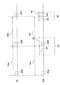
図1は、発振器6からクロック信号を受信し、アナログ無線送信回路8を制御するマイクロプロセッサ4を有するマスタ装置2を示している。マスタ装置2は、無線信号を送信するための無線アンテナ10も有している。
FIG. 1 shows a
同様に、発振器16からクロック信号を受信し、アナログ無線受信回路18を制御するマイクロプロセッサ14を有するスレーブ装置12もまた示されている。スレーブ装置12は、マスタ装置2から無線信号を受信するための無線アンテナ20を有している。
Similarly, a
なお、これらの構成要素は概略的に示されており、任意の適切な形態であってよい。実施形態によっては、マイクロプロセッサ4、14およびマスタ装置2またはスレーブ装置12のアナログ回路8、18は、ラジオ・オン・チップに一体化されてもよい。このようなチップは、アンテナ10、20および/または発振器6、16を備えてもよい。発振器6、16は、水晶発振器または抵抗・コンデンサ発振器または他の任意の適切な発振器であればよい。
These components are shown schematically and may be in any suitable form. In some embodiments, the
マスタ装置2が無線受信回路も備え、スレーブ装置12が無線送信回路も備えて、これら二台の間で双方向通信ができるようにしてもよい。
The
マスタ装置2とスレーブ装置12は、実質的にブルートゥース低エネルギー仕様に従って、無線データを交換するように構成されてもよい。
図3は、本発明の実施形態に係る、マスタ装置2からスレーブ装置12へのデータ伝送を概略的に示した図である。水平時間軸は、一定の縮尺ではない(特に、データパケットの合間のスリープ期間は、典型的には、受信ウィンドウより何倍も長いであろう)。
FIG. 3 is a diagram schematically showing data transmission from the
スレーブ装置12の受信ウィンドウのタイミングに直接関係しない、マスタ装置2とスレーブ装置12の構成要素は、ブルートゥース低エネルギー仕様に従ったものであればよい。
The constituent elements of the
例示したデータ交換において、マスタ装置2(TX)は、一連のデータパケット22a’、22b’、22c’を等間隔で送信し、それらは各接続イベント開始の目印としてもよい。他のデータパケット(図示せず)が、これらの接続イベントデータパケット22a’、22b’、22c’の一つのすぐあとで、マスタ装置2とスレーブ装置12との間でいずれかの方向に送信されてもよい。ある接続イベント内のデータ交換が停止すると、スレーブ装置12(RX)はスリープモードになり、その中の送信回路18の一部または全体および/またはマイクロプロセッサ論理回路16の一部の電源を落としてもよい。スレーブ装置12は、伝送中はより正確な発振器を使用し、スリープモード中のクロック信号にはより低電力で精度の低い発振器16を使用するように戻してもよい。
In the illustrated data exchange, the master device 2 (TX) transmits a series of
(潜在的に、送信回路8および/または受信回路18の内部遅延による)いかなる伝送遅延も無視、または調整するとして、データパケット22a’、22b’、22c’はそれぞれ、スレーブ装置12によって瞬時に受信されると考えられる。しかしながら、送信発振器6と受信発振器16は非同期であるため、スレーブ装置12で測定された、連続する接続イベントデータパケット22a’、22b’および22b’、22c’のそれぞれの間隔34a、34bの長さは、マスタ装置2で測定されたそれらの長さ24a’、24b’とは異なるかもしれない。マスタ装置2は、接続イベントデータパケットを等間隔で送信しようとするものの、実際には、それらの間隔は実時間に対して不正確であり、さらに、スレーブ装置12のクロック信号に対しては明らかに不正確である可能性がある。
The
セッションの最初の二つのパケットについては、スレーブ装置12は、慎重なアプローチで取り組み、パケット22b’の到着予定時刻前に比較的長い期間30’を開始する、比較的広い受信ウィンドウ28’を開いてもよい。そうすれば、パケットがすぐ受信されない場合でも、到着予定時刻の後に比較的長い最大期間32’にわたってウィンドウ28’を開いたままにしておくことができる。
For the first two packets of the session, the
しかしながら、その後のパケットについては、スレーブ装置12は、二つの直前に受信された接続イベントパケット22a’、22b’の間の実際の測定間隔34aを記録し、この測定値を用いて次のデータパケット22c’の到着予定時刻を決定することによって、マスタ装置2とスレーブ装置12のクロック信号の間で徐々に変化していくずれを補正する。二つの直前に受信されたデータパケット22a’、22b’の間隔34aのサイズは、継続的に更新される変数としてレジスタまたはメモリに保管してもよい。これは事実上、マスタとスレーブのクロック信号間の相対的なタイミング誤差を非常に低いメモリ要件で測定することになり、このことは低価格装置では特に好都合である。
However, for subsequent packets, the
これらの後続パケットについては、スレーブ装置12は、次のデータパケット22c’の到着予定時刻前の比較的短い期間38の間、受信可能状態になる、 すなわち受信ウィンドウ36を開けることができる。この期間38は、急速に変化するクロック誤差と徐々に変化するクロック誤差の両方に対処するのではなく、急速に変化するクロック誤差に対処するだけでよいので、図2の従来技術の実装における同等の期間30よりも小さくて済む。標準期間38は、一定の継続時間であっても、または可変であって、例えば、パケット損失率に応じて変えてもよい。受信ウィンドウ36は、パケットがデータパケット22c’の到着予定時刻までに受信されない場合でも、当該時刻のあと同じ期間40にわたって開いたままであってもよい。
With respect to these subsequent packets, the
データパケット22c’が、もしかして電波干渉かスレーブ装置12がマスタ装置2の圏外に移動したか 、またはおそらく極端に短期的な誤差のため、正しく受信されない場合、スレーブ装置12は、直前に受信した二つのデータパケット22a’、22b’ の間隔に対応する期間が再度経過した後に、さらにデータパケットが来るのを待ってもよいが、最後に正常受信した接続イベントデータパケットに対してモデル化された短期的な変動を状況に合わせて比例的に補正するために、この次のデータパケット用の受信ウィンドウ幅は増やしてもよい。この受信ウィンドウは、最後に受信したデータパケット22b’から経過した時間量に応じて直線的に大きさを増やしてもよい。データパケットがいくつか失われた後には、その接続が失われたとみなして、再同期化処理が開始されてもよい。
If the
本発明を用いて可能な節減の一例として、連続するデータパケット22a、22b、22cの間隔は一秒であるものとする。マスタクロック信号とスレーブクロック信号間の最大の相対的ずれは、通常、1000百万分率(ppm)であり、そのうち徐々に変化するずれは、通常、950ppmを占め、急速に変化する誤差は、通常、50ppmを占める。図2の従来技術のアプローチでは、受信ウィンドウ28は、各データパケットの予想到着時刻一ミリ秒前に開けられる。データパケットがほぼ予想時刻に到着すると仮定すると、結果的にスレーブ装置の受信回路が平均して毎秒一ミリ秒不必要に稼働状態となる。
As an example of the savings possible using the present invention, the interval between
対照的に、図3の本実施形態では、受信ウィンドウ36は、各データパケットの予想到着時刻50マイクロ秒前に開けられる。予想される時に、データパケットがほぼ予想時刻に到着すると仮定すると、結果的にスレーブ装置12の受信回路18は平均して毎秒50マイクロ秒しか不必要に稼働状態とならず、かなり省電力になる。
In contrast, in the present embodiment of FIG. 3, the receive
Claims (41)
前記無線送信機は、送信機クロック信号を用いて一連の接続イベントデータパケットを所定のスケジュールに従って無線で送信するように構成され、前記無線受信機は、
前記無線送信機から連続した接続イベントデータパケットを受信する合間にスリープ状態に入り、そのスリープ状態では、前記無線受信機が前記無線送信機からの無線伝送を受信して処理することはないように構成され、かつ
受信機クロック信号を用いて、一つの前記接続イベントデータパケットを受信してから所定数の受信機クロックサイクルが経過したときを判断し、それに応えて、前記無線受信機が前記無線送信機からの無線伝送を受信して処理することができる対応可能状態になるように構成されるが、ここで前記所定数の受信機クロックサイクルは、前記無線受信機によって受信された二つの前記接続イベントデータパケットをそれぞれ受信する間に経過した受信機クロックサイクル数から補正係数を差し引いたものである
ことを特徴とする無線通信システム。 A wireless communication system comprising a wireless transmitter and a wireless receiver configured to receive wireless transmission from the wireless transmitter,
The wireless transmitter is configured to wirelessly transmit a series of connection event data packets according to a predetermined schedule using a transmitter clock signal, and the wireless receiver includes:
A sleep state is entered between successive reception of connection event data packets from the wireless transmitter so that the wireless receiver does not receive and process wireless transmissions from the wireless transmitter in that sleep state. A receiver clock signal is used to determine when a predetermined number of receiver clock cycles have elapsed since receiving one of the connection event data packets, and in response, the wireless receiver Configured to be ready to receive and process wireless transmissions from a transmitter, wherein the predetermined number of receiver clock cycles are two of the two received by the wireless receiver Subtract the correction factor from the number of receiver clock cycles that have elapsed while receiving each connection event data packet Wireless communication system according to claim.
ことを特徴とする、請求項1に記載の無線通信システム。 The wireless communication system according to claim 1, wherein the two connection event data packets are connection event data packets received successively.
ことを特徴とする、請求項2に記載の無線通信システム。 The wireless communication system according to claim 2, wherein the two connection event data packets are the two connection event data packets received immediately before.
ことを特徴とする、請求項1乃至請求項3のいずれか一項に記載の無線通信システム。 The wireless receiver is configured to update a variable stored in memory with a value related to the number of receiver clock cycles that have elapsed between receiving each of the two connection event data packets. The wireless communication system according to any one of claims 1 to 3.
ことを特徴とする、請求項4に記載の無線通信システム。 The wireless communication system according to claim 4, wherein the wireless receiver is configured to update the variable every time a connection event data packet is received.
ことを特徴とする、請求項1乃至請求項5のいずれか一項に記載の無線通信システム。 The wireless communication system according to any one of claims 1 to 5, wherein the correction coefficient increases with the number of receiver clock cycles that have elapsed since the last connection event data packet was received.
ことを特徴とする、請求項1乃至請求項6のいずれか一項に記載の無線通信システム。 The correction coefficient is obtained by multiplying a predetermined basic value by the number of receiver clock cycles that have elapsed since the last connection event data packet was received. The wireless communication system according to one item.
ことを特徴とする、請求項1乃至請求項5のいずれか一項に記載の無線通信システム。 The wireless communication system according to any one of claims 1 to 5, wherein the correction coefficient is constant while connected to a transmitter.
ことを特徴とする、請求項1乃至請求項8のいずれか一項に記載の無線通信システム。 The wireless communication system according to any one of claims 1 to 8, wherein the correction coefficient depends on timing information related to a received connection event data packet.
ことを特徴とする、請求項1乃至請求項9のいずれか一項に記載の無線通信システム。 The wireless communication system according to any one of claims 1 to 9, wherein the correction coefficient depends on a difference between an expected reception time and an actual reception time of a connection event data packet.
ことを特徴とする、請求項1乃至請求項10のいずれか一項に記載の無線通信システム。 The wireless communication system according to any one of claims 1 to 10, wherein the wireless transmitter is configured to periodically transmit a series of connection event data packets.
前記無線送信機が、送信機クロック信号を用いて一連の接続イベントデータパケットを所定のスケジュールに従って無線で送信するステップと、
前記無線受信機が、前記無線送信機から連続した接続イベントデータパケットを受信する合間にスリープ状態に入り、そのスリープ状態では、前記無線受信機が前記無線送信機からの無線伝送を受信して処理することはないステップと、
前記無線受信機が、受信機クロック信号を用いて、一つの接続イベントデータパケットを受信してから所定数の受信機クロックサイクルが経過したときを判断し、それに応えて、前記無線受信機が前記無線送信機からの無線伝送を受信して処理することができる対応可能状態になることを含むが、ここで前記所定数の受信機クロックサイクルは、前記無線受信機によって受信された二つの前記接続イベントデータパケットをそれぞれ受信する間に経過した受信機クロックサイクル数から補正係数を差し引いたものであるステップと、を含む
ことを特徴とする方法。 A method for operating a wireless transmitter and a wireless receiver, comprising:
The wireless transmitter wirelessly transmitting a series of connection event data packets using a transmitter clock signal according to a predetermined schedule;
The wireless receiver enters a sleep state between receiving successive connection event data packets from the wireless transmitter, in which the wireless receiver receives and processes wireless transmissions from the wireless transmitter. Steps that you never do,
The wireless receiver uses a receiver clock signal to determine when a predetermined number of receiver clock cycles have elapsed since receiving one connection event data packet, and in response, the wireless receiver Including being ready to receive and process wireless transmissions from a wireless transmitter, wherein the predetermined number of receiver clock cycles are two of the connections received by the wireless receiver And a step of subtracting a correction factor from the number of receiver clock cycles that have elapsed between each reception of the event data packet.
ことを特徴とする、請求項12に記載の方法。 The method of claim 12, wherein the two connection event data packets are connection event data packets received in succession.
ことを特徴とする、請求項13に記載の方法。 The method of claim 13, wherein the two connection event data packets are two connection event data packets received immediately before.
ことを特徴とする、請求項12乃至請求項14のいずれか一項に記載の方法。 The wireless receiver further comprising updating a variable stored in a memory with a value related to the number of receiver clock cycles that have elapsed between receiving each of the two connection event data packets. 15. The method according to any one of claims 12 to 14, wherein:
ことを特徴とする、請求項15に記載の方法。 The method of claim 15, wherein the wireless receiver updates the variable every time it finishes receiving a connection event data packet.
ことを特徴とする、請求項12乃至請求項16のいずれか一項に記載の方法。 The method according to any one of claims 12 to 16, characterized in that the correction factor increases with the number of receiver clock cycles that have elapsed since the last connection event data packet was received.
ことを特徴とする、請求項12乃至請求項17のいずれか一項に記載の方法。 18. The correction coefficient according to claim 12, wherein the correction coefficient is a predetermined basic value multiplied by the number of receiver clock cycles that have elapsed since the last connection event data packet was received. The method according to one item.
ことを特徴とする、請求項12乃至請求項16のいずれか一項に記載の方法。 The method according to any one of claims 12 to 16, wherein the correction factor is constant while connected to a transmitter.
ことを特徴とする、請求項12乃至請求項19のいずれか一項に記載の方法。 The method according to any one of claims 12 to 19, wherein the correction factor depends on timing information associated with a received connection event data packet.
ことを特徴とする、請求項12乃至請求項20のいずれか一項に記載の方法。 The method according to any one of claims 12 to 20, wherein the correction factor depends on a difference between an expected reception time and an actual reception time of a connection event data packet.
ことを特徴とする、請求項12乃至請求項21のいずれか一項に記載の方法。 The method according to any one of claims 12 to 21, wherein the wireless transmitter periodically transmits a series of connection event data packets.
前記無線受信機は、
前記無線送信機から連続した接続イベントデータパケットを受信する合間にスリープ状態に入り、そのスリープ状態では、前記無線受信機が前記無線送信機からの無線伝送を受信して処理することはないように構成され、かつ
受信機クロック信号を用いて、一つの前記接続イベントデータパケットを受信してから所定数の受信機クロックサイクルが経過したときを判断し、それに応えて、前記無線受信機が前記無線送信機からの無線伝送を受信して処理することができる対応可能状態になるように構成されるが、ここで前記所定数の受信機クロックサイクルは、前記無線受信機によって受信された二つの前記接続イベントデータパケットをそれぞれ受信する合間に経過した受信機クロックサイクル数から補正係数を差し引いたものである
ことを特徴とする無線受信機。 A wireless receiver suitable for receiving a wireless transmission from a wireless transmitter that wirelessly transmits a series of connection event data packets according to a predetermined schedule,
The wireless receiver
A sleep state is entered between successive reception of connection event data packets from the wireless transmitter so that the wireless receiver does not receive and process wireless transmissions from the wireless transmitter in that sleep state. A receiver clock signal is used to determine when a predetermined number of receiver clock cycles have elapsed since receiving one of the connection event data packets, and in response, the wireless receiver Configured to be ready to receive and process wireless transmissions from a transmitter, wherein the predetermined number of receiver clock cycles are two of the two received by the wireless receiver This is the number of receiver clock cycles that have passed between each connection event data packet reception minus the correction factor. Radio receiver according to claim.
ことを特徴とする、請求項23に記載の無線受信機。 The wireless receiver according to claim 23, wherein the two connection event data packets are connection event data packets received successively.
ことを特徴とする、請求項24に記載の無線受信機。 The wireless receiver according to claim 24, wherein the two connection event data packets are two connection event data packets received immediately before.
ことを特徴とする、請求項23乃至請求項25のいずれか一項に記載の無線受信機。 The wireless receiver is configured to update a variable stored in memory with a value related to the number of receiver clock cycles that have elapsed between receiving each of the two connection event data packets. The wireless receiver according to any one of claims 23 to 25.
ことを特徴とする、請求項26に記載の無線受信機。 27. The wireless receiver according to claim 26, wherein the wireless receiver is configured to update the variable every time a connection event data packet is received.
ことを特徴とする、請求項23乃至請求項27のいずれか一項に記載の無線受信機。 The wireless receiver according to any one of claims 23 to 27, wherein the correction factor increases with the number of receiver clock cycles that have elapsed since the last connection event data packet was received.
ことを特徴とする、請求項23乃至請求項28のいずれか一項に記載の無線受信機。 The correction coefficient is obtained by multiplying a predetermined basic value by the number of receiver clock cycles that have elapsed since the last connection event data packet was received. The wireless receiver according to one item.
ことを特徴とする、請求項23乃至請求項27のいずれか一項に記載の無線受信機。 The wireless receiver according to any one of claims 23 to 27, wherein the correction coefficient is constant while connected to a transmitter.
ことを特徴とする、請求項23乃至請求項30のいずれか一項に記載の無線受信機。 The wireless receiver according to any one of claims 23 to 30, wherein the correction coefficient depends on timing information related to a received connection event data packet.
ことを特徴とする、請求項23乃至請求項31のいずれか一項に記載の無線受信機。 32. The wireless receiver according to claim 23, wherein the correction coefficient depends on a difference between an expected reception time and an actual reception time of a connection event data packet.
前記無線送信機は、送信機クロック信号を用いて、連続したデータパケットの合間に一定数の送信機クロックサイクルが経過するようにしながら、無線で規則正しい一連の接続イベントデータパケットを送信するように構成され、
前記送信機クロック信号の周期は、前記一定数の送信機クロック・サイクルが継続するうちは、第一の所定最大百万分率(ppm)の誤差に至るまでの期間にわたって安定しており、
前記無線受信機は、前記無線送信機から連続した接続イベントデータパケットを受信する合間にスリープ状態になるように構成され、その状態では、前記無線受信機は前記無線送信機から無線伝送を受信して処理することは行わず、かつ
前記一定数の送信機クロック・サイクルが継続するうちは、第二の所定最大百万分率(ppm)の誤差に至るまでの期間にわたって安定している受信機クロック信号を用いて、受信可能状態になってそのまま留まるように構成され、その状態では、前記無線受信機は前記無線送信機から無線伝送を受信し処理することができ、その状態に留まる長さは、前記第一の所定最大百万分率(ppm)の誤差と前記第二の所定最大百万分率(ppm)の誤差の合計に、直前に受信した接続イベントデータパケットと次の接続イベントデータパケットの到着予定時刻との間の受信機クロックサイクル数を乗じたものの二倍よりも実質的に大きくない受信機クロックサイクル数である
ことを特徴とする無線通信システム。 A wireless communication system comprising a wireless transmitter and a wireless receiver configured to receive wireless transmission from the wireless transmitter,
The wireless transmitter is configured to transmit a series of ordered connection event data packets wirelessly using a transmitter clock signal while a fixed number of transmitter clock cycles elapse between successive data packets. And
The period of the transmitter clock signal is stable over a period up to the first predetermined maximum parts per million (ppm) error as long as the fixed number of transmitter clock cycles continues;
The wireless receiver is configured to enter a sleep state between receiving successive connection event data packets from the wireless transmitter, in which state the wireless receiver receives a wireless transmission from the wireless transmitter. A receiver that is stable over a period of time until the second predetermined maximum parts per million (ppm) error is achieved as long as the fixed number of transmitter clock cycles continue. It is configured to remain in a receivable state using a clock signal, and in that state, the wireless receiver can receive and process a wireless transmission from the wireless transmitter, and the length to remain in that state. Is the sum of the error of the first predetermined maximum parts per million (ppm) and the error of the second predetermined maximum parts per million (ppm), and the connection event data packet received immediately before A wireless communication system, characterized in that the number of receiver clock cycles is not substantially greater than twice the number of receiver clock cycles multiplied by the estimated arrival time of the next connection event data packet.
ことを特徴とする、請求項33に記載の無線通信システム。 34. The radio of claim 33, wherein the radio receiver is configured to be ready for reception earlier than half the maximum reception window duration from the expected arrival time of the next connection event data packet. Communications system.
前記無線送信機が、送信機クロック信号を用いて、連続したデータパケットの合間に一定数の送信機クロックサイクルが経過するようにしながら、無線で規則正しい一連の接続イベントデータパケットを送信し、ここで、前記送信機クロック信号の周期は、前記一定数の送信機クロック・サイクルが継続するうちは、第一の所定最大百万分率(ppm)の誤差に至るまでの期間にわたって安定しているステップと、
前記無線受信機が、前記無線送信機から連続した接続イベントデータパケットを受信する合間にスリープ状態になり、その状態では、前記無線受信機は前記無線送信機から無線伝送を受信して処理することは行わないステップと、
前記無線受信機が、前記一定数の送信機クロック・サイクルが継続するうちは、第二の所定最大百万分率(ppm)の誤差に至るまでの期間にわたって安定している受信機クロック信号を用いて、受信可能状態になってそのまま留まり、その状態では、前記無線受信機は前記無線送信機から無線伝送を受信し処理することができ、その状態に留まる長さは、前記第一の所定最大百万分率(ppm)の誤差と前記第二の所定最大百万分率(ppm)の誤差の合計に、直前に受信した接続イベントデータパケットと次の接続イベントデータパケットの到着予定時刻との間の受信機クロックサイクル数を乗じたものの二倍よりも実質的に大きくない受信機クロックサイクル数であるステップと、を含む
ことを特徴とする方法。 A method for operating a wireless transmitter and a wireless receiver, comprising:
The wireless transmitter uses a transmitter clock signal to transmit a series of regular connection event data packets wirelessly, such that a certain number of transmitter clock cycles elapse between successive data packets, where The period of the transmitter clock signal is stable over a period up to the first predetermined maximum parts per million (ppm) error as long as the fixed number of transmitter clock cycles continues. When,
The wireless receiver goes to sleep between receiving successive connection event data packets from the wireless transmitter, in which state the wireless receiver receives and processes wireless transmissions from the wireless transmitter. Steps that do not
A receiver clock signal that is stable over a period of time until the radio receiver reaches a second predetermined maximum parts-per-million (ppm) error as long as the fixed number of transmitter clock cycles continues. The wireless receiver can receive and process the wireless transmission from the wireless transmitter, and the length of the state remaining in the state is the first predetermined length. The sum of the error of maximum parts per million (ppm) and the error of the second predetermined maximum parts per million (ppm) includes the arrival time of the connection event data packet received immediately before and the next connection event data packet. A receiver clock cycle number that is not substantially greater than twice the receiver clock cycle number between.
ことを特徴とする、請求項35に記載の方法。 36. The method according to claim 35, comprising the step of the wireless receiver being ready for reception by half of the maximum reception window duration from the estimated arrival time of the next connection event data packet.
前記送信機クロック信号の周期は、前記一定数の送信機クロック・サイクルが継続するうちは、第一の所定最大百万分率(ppm)の誤差に至るまでの期間にわたって安定しており、
前記無線受信機は、前記無線送信機から連続した接続イベントデータパケットを受信する合間にスリープ状態になるように構成され、その状態では、前記無線受信機は前記無線送信機から無線伝送を受信して処理することは行わず、かつ
前記一定数の送信機クロック・サイクルが継続するうちは、第二の所定最大百万分率(ppm)の誤差に至るまでの期間にわたって安定している受信機クロック信号を用いて、受信可能状態になってそのまま留まるように構成され、その状態では、前記無線受信機は前記無線送信機から無線伝送を受信し処理することができ、その状態に留まる長さは、前記第一の所定最大百万分率(ppm)の誤差と前記第二の所定最大百万分率(ppm)の誤差の合計に、直前に受信した接続イベントデータパケットと次の接続イベントデータパケットの到着予定時刻との間の受信機クロックサイクル数を乗じたものの二倍よりも実質的に大きくない受信機クロックサイクル数である
ことを特徴とする無線受信機。 Receives radio transmissions from radio transmitters that transmit a series of ordered connection event data packets over the air using a transmitter clock signal so that a fixed number of transmitter clock cycles elapse between successive data packets A wireless receiver suitable for
The period of the transmitter clock signal is stable over a period up to the first predetermined maximum parts per million (ppm) error as long as the fixed number of transmitter clock cycles continues;
The wireless receiver is configured to enter a sleep state between receiving successive connection event data packets from the wireless transmitter, in which state the wireless receiver receives a wireless transmission from the wireless transmitter. A receiver that is stable over a period of time until the second predetermined maximum parts per million (ppm) error is achieved as long as the fixed number of transmitter clock cycles continue. It is configured to remain in a receivable state using a clock signal, and in that state, the wireless receiver can receive and process a wireless transmission from the wireless transmitter, and the length to remain in that state. Is the sum of the error of the first predetermined maximum parts per million (ppm) and the error of the second predetermined maximum parts per million (ppm), and the connection event data packet received immediately before A wireless receiver characterized in that the number of receiver clock cycles is not substantially greater than twice the number of receiver clock cycles multiplied by the estimated arrival time of the next connection event data packet.
ことを特徴とする、請求項37に記載の無線受信機。 38. The wireless receiver according to claim 37, wherein the wireless receiver is configured to be ready for reception earlier than half the maximum reception window continuation period from the estimated arrival time of the next connection event data packet.
前記無線送信機は、送信機クロック信号を用いて一連の接続イベントデータパケットを所定のスケジュールに従って無線で送信するように構成され、
前記無線受信機は、
前記無線送信機から連続した接続イベントデータパケットを受信する合間にスリープ状態に入り、そのスリープ状態では、前記無線受信機が前記無線送信機からの無線伝送を受信して処理することはないように構成され、かつ
受信機クロック信号を用いて、一つの前記接続イベントデータパケットを受信してから所定数の受信機クロックサイクルが経過したときを判断し、それに応えて、前記無線受信機が前記無線送信機からの無線伝送を受信して処理することができる対応可能状態になるように構成されるが、ここで前記所定数の受信機クロックサイクルは、前記無線受信機によって受信された二つの前記接続イベントデータパケットをそれぞれ受信する合間に受信機クロックサイクルが何回経過したかに依存する
ことを特徴とする無線通信システム。 A wireless communication system comprising a wireless transmitter and a wireless receiver configured to receive wireless transmission from the wireless transmitter,
The wireless transmitter is configured to wirelessly transmit a series of connection event data packets according to a predetermined schedule using a transmitter clock signal;
The wireless receiver
A sleep state is entered between successive reception of connection event data packets from the wireless transmitter so that the wireless receiver does not receive and process wireless transmissions from the wireless transmitter in that sleep state. A receiver clock signal is used to determine when a predetermined number of receiver clock cycles have elapsed since receiving one of the connection event data packets, and in response, the wireless receiver Configured to be ready to receive and process wireless transmissions from a transmitter, wherein the predetermined number of receiver clock cycles are two of the two received by the wireless receiver Dependent on how many receiver clock cycles have elapsed between each connection event data packet reception Shin system.
前記無線送信機が、送信機クロック信号を用いて一連の接続イベントデータパケットを所定のスケジュールに従って無線で送信するステップと、
前記無線受信機が、前記無線送信機から連続した接続イベントデータパケットを受信する合間にスリープ状態に入り、そのスリープ状態では、前記無線受信機が前記無線送信機からの無線伝送を受信して処理することはないステップと、
前記無線受信機が、受信機クロック信号を用いて、一つの前記接続イベントデータパケットを受信してから所定数の受信機クロックサイクルが経過したときを判断し、それに応えて、前記無線受信機が前記無線送信機からの無線伝送を受信して処理することができる対応可能状態になることを含むが、ここで前記所定数の受信機クロックサイクルは、前記無線受信機によって受信された前記接続イベントデータパケットのうち二つをそれぞれ受信する合間に受信機クロックサイクルが何回経過したかに依存するステップと、を含む
ことを特徴とする方法。 A method for operating a wireless transmitter and a wireless receiver, comprising:
The wireless transmitter wirelessly transmitting a series of connection event data packets using a transmitter clock signal according to a predetermined schedule;
The wireless receiver enters a sleep state between receiving successive connection event data packets from the wireless transmitter, in which the wireless receiver receives and processes wireless transmissions from the wireless transmitter. Steps that you never do,
The wireless receiver uses a receiver clock signal to determine when a predetermined number of receiver clock cycles have elapsed since receiving one of the connection event data packets, and in response, the wireless receiver Including being ready to receive and process wireless transmissions from the wireless transmitter, wherein the predetermined number of receiver clock cycles includes the connection event received by the wireless receiver. Depending on how many receiver clock cycles have elapsed between receiving each of the two of the data packets.
前記無線受信機は、
前記無線送信機から連続した接続イベントデータパケットを受信する合間にスリープ状態に入り、そのスリープ状態では、前記無線受信機が前記無線送信機からの無線伝送を受信して処理することはないように構成され、かつ
受信機クロック信号を用いて、一つの前記接続イベントデータパケットを受信してから所定数の受信機クロックサイクルが経過したときを判断し、それに応えて、前記無線受信機が前記無線送信機からの無線伝送を受信して処理することができる対応可能状態になるように構成されるが、ここで前記所定数の受信機クロックサイクルは、前記無線受信機によって受信された二つの前記接続イベントデータパケットをそれぞれ受信する合間に受信機クロックサイクルが何回経過したかに依存する
ことを特徴とする無線受信機。 A wireless receiver suitable for receiving a wireless transmission from a wireless transmitter that wirelessly transmits a series of connection event data packets according to a predetermined schedule,
The wireless receiver
A sleep state is entered between successive reception of connection event data packets from the wireless transmitter so that the wireless receiver does not receive and process wireless transmissions from the wireless transmitter in that sleep state. A receiver clock signal is used to determine when a predetermined number of receiver clock cycles have elapsed since receiving one of the connection event data packets, and in response, the wireless receiver Configured to be ready to receive and process wireless transmissions from a transmitter, wherein the predetermined number of receiver clock cycles are two of the two received by the wireless receiver Dependent on how many receiver clock cycles have elapsed between each connection event data packet reception Shin machine.
Applications Claiming Priority (3)
| Application Number | Priority Date | Filing Date | Title |
|---|---|---|---|
| GB1115517.3 | 2011-09-08 | ||
| GB201115517A GB2490974B (en) | 2011-09-08 | 2011-09-08 | Radio communication system |
| PCT/GB2012/052207 WO2013034924A1 (en) | 2011-09-08 | 2012-09-07 | Radio communication system |
Publications (2)
| Publication Number | Publication Date |
|---|---|
| JP2014526821A true JP2014526821A (en) | 2014-10-06 |
| JP2014526821A5 JP2014526821A5 (en) | 2015-09-17 |
Family
ID=44908252
Family Applications (1)
| Application Number | Title | Priority Date | Filing Date |
|---|---|---|---|
| JP2014529069A Pending JP2014526821A (en) | 2011-09-08 | 2012-09-07 | Wireless communication system |
Country Status (8)
| Country | Link |
|---|---|
| US (2) | US9398534B2 (en) |
| EP (1) | EP2749087B1 (en) |
| JP (1) | JP2014526821A (en) |
| KR (1) | KR20140060570A (en) |
| CN (1) | CN103947262B (en) |
| GB (1) | GB2490974B (en) |
| TW (1) | TWI552553B (en) |
| WO (1) | WO2013034924A1 (en) |
Cited By (1)
| Publication number | Priority date | Publication date | Assignee | Title |
|---|---|---|---|---|
| CN105992132A (en) * | 2015-03-23 | 2016-10-05 | 卡西欧计算机株式会社 | Wireless communication device and wireless communication method |
Families Citing this family (18)
| Publication number | Priority date | Publication date | Assignee | Title |
|---|---|---|---|---|
| GB2490974B (en) * | 2011-09-08 | 2014-10-29 | Nordic Semiconductor Asa | Radio communication system |
| US10419907B2 (en) | 2012-02-22 | 2019-09-17 | Qualcomm Incorporated | Proximity application discovery and provisioning |
| US9544075B2 (en) | 2012-02-22 | 2017-01-10 | Qualcomm Incorporated | Platform for wireless identity transmitter and system using short range wireless broadcast |
| US10360593B2 (en) | 2012-04-24 | 2019-07-23 | Qualcomm Incorporated | Retail proximity marketing |
| KR102201616B1 (en) * | 2014-02-23 | 2021-01-12 | 삼성전자주식회사 | Method of Searching Device Between Electrical Devices |
| EP3138328B1 (en) | 2014-05-01 | 2021-04-21 | Nokia Technologies Oy | Method and apparatus for connecting to a node of a mesh network |
| US8990556B1 (en) | 2014-08-13 | 2015-03-24 | Gimbal, Inc. | Sharing beacons |
| CN104615016B (en) * | 2014-12-08 | 2017-06-30 | 广东欧珀移动通信有限公司 | A kind of method and device based on low-power consumption bluetooth technical controlling main frame |
| US9107152B1 (en) | 2015-03-11 | 2015-08-11 | Gimbal, Inc. | Beacon protocol advertising bi-directional communication availability window |
| US10098068B2 (en) * | 2016-02-12 | 2018-10-09 | Semiconductor Components Industries, Llc | Power optimization system and method for low power devices |
| TWI627860B (en) * | 2016-05-31 | 2018-06-21 | 晨星半導體股份有限公司 | Video processing device and method |
| US10045297B1 (en) * | 2017-01-24 | 2018-08-07 | Google Llc | Increased time in a suspended state during network transmissions |
| DE102018004815B4 (en) * | 2018-06-08 | 2019-12-24 | Diehl Metering Systems Gmbh | Method for operating a radio transmission system and arrangement of a radio transmission system |
| GB201912412D0 (en) | 2019-08-29 | 2019-10-16 | Forkbeard Tech As | Position determination |
| EP3849249B1 (en) * | 2020-01-09 | 2023-06-14 | Stichting IMEC Nederland | System and method for generating time reference in duty-cycled wireless communications |
| CN114980322A (en) * | 2021-02-26 | 2022-08-30 | 恩智浦有限公司 | Improved window widening |
| CN115913449A (en) * | 2021-08-03 | 2023-04-04 | 华为技术有限公司 | Data transmission method and device |
| CN115038153B (en) * | 2022-08-10 | 2022-12-13 | 广州安凯微电子股份有限公司 | Low-power-consumption Bluetooth chip sleep mode control method and system |
Citations (5)
| Publication number | Priority date | Publication date | Assignee | Title |
|---|---|---|---|---|
| JPH04213229A (en) * | 1990-12-07 | 1992-08-04 | Nippon Telegr & Teleph Corp <Ntt> | Intermittent reception circuit for radio calling receiver |
| JP2002209264A (en) * | 2001-01-11 | 2002-07-26 | Mitsubishi Electric Corp | Mobile terminal and its intermittent reception method |
| JP2008048027A (en) * | 2006-08-11 | 2008-02-28 | Osasi Technos Inc | Network system |
| JP2009219091A (en) * | 2008-03-13 | 2009-09-24 | Nippon Telegr & Teleph Corp <Ntt> | Intermittent receiving apparatus |
| WO2010014992A1 (en) * | 2008-08-01 | 2010-02-04 | Qualcomm Incorporated | Method and apparatus for receiving a transmission at a receiver |
Family Cites Families (21)
| Publication number | Priority date | Publication date | Assignee | Title |
|---|---|---|---|---|
| US5155479A (en) * | 1989-10-17 | 1992-10-13 | Seiko Corp. | Radio receiver with adaptive on-off control |
| GB9304638D0 (en) * | 1993-03-06 | 1993-04-21 | Ncr Int Inc | Wireless data communication system having power saving function |
| DE60033503T2 (en) * | 2000-06-09 | 2007-11-08 | Motorola, Inc., Schaumburg | Time synchronization for mobile radio systems |
| US7023884B2 (en) | 2000-12-19 | 2006-04-04 | Lucent Technologies Inc. | Clock offset estimation with bias correction |
| US7120390B2 (en) | 2001-03-21 | 2006-10-10 | Agere Systems Inc. | BLUETOOTH smart offset compensation |
| GB2379581B (en) * | 2001-09-11 | 2005-08-31 | Nec Technologies | Apparatus and method of compensation for signal time-of-arrival variation in a UMTS handset |
| JP2004008027A (en) * | 2002-06-04 | 2004-01-15 | Japan Science & Technology Corp | New peptide having camp-producing activity |
| US20040043797A1 (en) * | 2002-08-30 | 2004-03-04 | Shostak Robert E. | Method and apparatus for power conservation in a wireless communication system |
| EP1467584A1 (en) * | 2003-04-11 | 2004-10-13 | Telefonaktiebolaget LM Ericsson (publ) | Method and apparatus for wireless intersystem handover |
| US7457973B2 (en) * | 2003-06-20 | 2008-11-25 | Texas Instruments Incorporated | System and method for prioritizing data transmission and transmitting scheduled wake-up times to network stations based on downlink transmission duration |
| US7321788B2 (en) * | 2003-09-11 | 2008-01-22 | Honeywell International, Inc. | Synchronizing RF system |
| US7197341B2 (en) * | 2003-12-22 | 2007-03-27 | Interdigital Technology Corporation | Precise sleep timer using a low-cost and low-accuracy clock |
| US7496774B2 (en) * | 2004-06-04 | 2009-02-24 | Broadcom Corporation | Method and system for generating clocks for standby mode operation in a mobile communication device |
| US20060056322A1 (en) * | 2004-09-10 | 2006-03-16 | Simpson Floyd D | Method for updating a timer function in a mobile station in a wireless local area network |
| KR100637079B1 (en) * | 2005-02-17 | 2006-10-23 | 삼성전자주식회사 | The device which control adaptively turn-on time of the tranceiver and the method thereof |
| US7606602B2 (en) * | 2005-08-11 | 2009-10-20 | Toshiba America Research, Inc. | Reducing power consumption of Wi-Fi enabled mobile devices |
| CN101601264B (en) * | 2007-02-01 | 2014-08-20 | Nxp股份有限公司 | Control of awake time in mobile device |
| KR101179931B1 (en) | 2008-12-11 | 2012-09-07 | 한국전자통신연구원 | Apparatus and method for estimating timing offset in a wireless communication system |
| US20100303185A1 (en) * | 2009-06-02 | 2010-12-02 | Jacobus Cornelis Haartsen | Methods of Operating Wireless Communications Devices Including Detecting Times of Receipt of Packets and Related Devices |
| WO2012149319A1 (en) * | 2011-04-29 | 2012-11-01 | Research In Motion Limited | Receiving messages in connection with lte wakeup |
| GB2490974B (en) * | 2011-09-08 | 2014-10-29 | Nordic Semiconductor Asa | Radio communication system |
-
2011
- 2011-09-08 GB GB201115517A patent/GB2490974B/en not_active Expired - Fee Related
-
2012
- 2012-09-06 TW TW101132488A patent/TWI552553B/en not_active IP Right Cessation
- 2012-09-07 KR KR1020147009200A patent/KR20140060570A/en not_active Application Discontinuation
- 2012-09-07 US US14/342,765 patent/US9398534B2/en active Active
- 2012-09-07 JP JP2014529069A patent/JP2014526821A/en active Pending
- 2012-09-07 WO PCT/GB2012/052207 patent/WO2013034924A1/en active Application Filing
- 2012-09-07 CN CN201280043839.2A patent/CN103947262B/en active Active
- 2012-09-07 EP EP12758880.4A patent/EP2749087B1/en active Active
-
2016
- 2016-06-15 US US15/183,706 patent/US10064133B2/en active Active
Patent Citations (5)
| Publication number | Priority date | Publication date | Assignee | Title |
|---|---|---|---|---|
| JPH04213229A (en) * | 1990-12-07 | 1992-08-04 | Nippon Telegr & Teleph Corp <Ntt> | Intermittent reception circuit for radio calling receiver |
| JP2002209264A (en) * | 2001-01-11 | 2002-07-26 | Mitsubishi Electric Corp | Mobile terminal and its intermittent reception method |
| JP2008048027A (en) * | 2006-08-11 | 2008-02-28 | Osasi Technos Inc | Network system |
| JP2009219091A (en) * | 2008-03-13 | 2009-09-24 | Nippon Telegr & Teleph Corp <Ntt> | Intermittent receiving apparatus |
| WO2010014992A1 (en) * | 2008-08-01 | 2010-02-04 | Qualcomm Incorporated | Method and apparatus for receiving a transmission at a receiver |
Cited By (5)
| Publication number | Priority date | Publication date | Assignee | Title |
|---|---|---|---|---|
| CN105992132A (en) * | 2015-03-23 | 2016-10-05 | 卡西欧计算机株式会社 | Wireless communication device and wireless communication method |
| JP2016178581A (en) * | 2015-03-23 | 2016-10-06 | カシオ計算機株式会社 | Radio communication apparatus, radio communication method and program |
| US10271294B2 (en) | 2015-03-23 | 2019-04-23 | Casio Computer Co., Ltd. | Wireless communication device, wireless communication method, and storage medium |
| CN105992132B (en) * | 2015-03-23 | 2019-11-01 | 卡西欧计算机株式会社 | Wireless communication device, wireless communication system and wireless communications method |
| US10477501B2 (en) | 2015-03-23 | 2019-11-12 | Casio Computer Co., Ltd. | Wireless communication device, wireless communication method, and storage medium |
Also Published As
| Publication number | Publication date |
|---|---|
| GB2490974A (en) | 2012-11-21 |
| GB2490974B (en) | 2014-10-29 |
| US20150109978A1 (en) | 2015-04-23 |
| CN103947262B (en) | 2018-01-19 |
| US20160295508A1 (en) | 2016-10-06 |
| US10064133B2 (en) | 2018-08-28 |
| EP2749087B1 (en) | 2018-06-27 |
| CN103947262A (en) | 2014-07-23 |
| KR20140060570A (en) | 2014-05-20 |
| TWI552553B (en) | 2016-10-01 |
| EP2749087A1 (en) | 2014-07-02 |
| WO2013034924A1 (en) | 2013-03-14 |
| GB201115517D0 (en) | 2011-10-26 |
| US9398534B2 (en) | 2016-07-19 |
| TW201312977A (en) | 2013-03-16 |
Similar Documents
| Publication | Publication Date | Title |
|---|---|---|
| JP2014526821A (en) | Wireless communication system | |
| US10152111B2 (en) | Low power timing, configuring, and scheduling | |
| CN106131947B (en) | A kind of synchronous method of clock between Wireless Communication Equipment | |
| US8384590B2 (en) | System and method for time synchronization | |
| US8160045B1 (en) | Beacon miss prevention in power save modes using timing synchronization function | |
| EP2854458B1 (en) | Wireless sensor time synchronization | |
| EP3039914B1 (en) | Method and apparatuses for discontinuous reception cycle estimation by data packet monitoring | |
| US11777862B2 (en) | Method of receiver window widening and autodrift calculation using packet timestamping | |
| US8179925B2 (en) | Sink device for a wireless local area network | |
| WO2008145053A1 (en) | A network clock synchronization method of short range wireless communication network | |
| JP5128353B2 (en) | Wireless node system, wireless node, and wireless node synchronization method | |
| WO2019138102A1 (en) | Clock calibration | |
| JP2019115036A (en) | Transceiver device with real-time clock | |
| US11353916B2 (en) | Clock-error estimation for two-clock electronic device | |
| JP6727524B2 (en) | Wireless transceiver system | |
| US20220386239A1 (en) | Wireless communication device and wireless communication system | |
| US20240098668A1 (en) | Calibration of a low frequency oscillator using a high frequency oscillator as a reference clock | |
| US11844038B2 (en) | Synchronization of wireless network nodes for efficient communications | |
| US8902877B2 (en) | Method and system for reducing power consumption in wireless communications by adjusting communication intervals | |
| JP2019118017A (en) | Wireless terminal device and communication system | |
| CN112602031A (en) | Accurate timing between systems |
Legal Events
| Date | Code | Title | Description |
|---|---|---|---|
| A521 | Written amendment |
Free format text: JAPANESE INTERMEDIATE CODE: A523 Effective date: 20150731 |
|
| A621 | Written request for application examination |
Free format text: JAPANESE INTERMEDIATE CODE: A621 Effective date: 20150731 |
|
| RD02 | Notification of acceptance of power of attorney |
Free format text: JAPANESE INTERMEDIATE CODE: A7422 Effective date: 20151116 |
|
| A977 | Report on retrieval |
Free format text: JAPANESE INTERMEDIATE CODE: A971007 Effective date: 20160524 |
|
| A131 | Notification of reasons for refusal |
Free format text: JAPANESE INTERMEDIATE CODE: A131 Effective date: 20160531 |
|
| A601 | Written request for extension of time |
Free format text: JAPANESE INTERMEDIATE CODE: A601 Effective date: 20160830 |
|
| A521 | Written amendment |
Free format text: JAPANESE INTERMEDIATE CODE: A523 Effective date: 20161028 |
|
| A131 | Notification of reasons for refusal |
Free format text: JAPANESE INTERMEDIATE CODE: A131 Effective date: 20170321 |
|
| A601 | Written request for extension of time |
Free format text: JAPANESE INTERMEDIATE CODE: A601 Effective date: 20170619 |
|
| A521 | Written amendment |
Free format text: JAPANESE INTERMEDIATE CODE: A523 Effective date: 20170821 |
|
| A02 | Decision of refusal |
Free format text: JAPANESE INTERMEDIATE CODE: A02 Effective date: 20180220 |