JP2014526659A - Chain link - Google Patents
Chain link Download PDFInfo
- Publication number
- JP2014526659A JP2014526659A JP2014530126A JP2014530126A JP2014526659A JP 2014526659 A JP2014526659 A JP 2014526659A JP 2014530126 A JP2014530126 A JP 2014530126A JP 2014530126 A JP2014530126 A JP 2014530126A JP 2014526659 A JP2014526659 A JP 2014526659A
- Authority
- JP
- Japan
- Prior art keywords
- crosspiece
- chain link
- chain
- engagement
- pivot
- Prior art date
- Legal status (The legal status is an assumption and is not a legal conclusion. Google has not performed a legal analysis and makes no representation as to the accuracy of the status listed.)
- Pending
Links
Images


Classifications
-
- H—ELECTRICITY
- H02—GENERATION; CONVERSION OR DISTRIBUTION OF ELECTRIC POWER
- H02G—INSTALLATION OF ELECTRIC CABLES OR LINES, OR OF COMBINED OPTICAL AND ELECTRIC CABLES OR LINES
- H02G11/00—Arrangements of electric cables or lines between relatively-movable parts
- H02G11/006—Arrangements of electric cables or lines between relatively-movable parts using extensible carrier for the cable, e.g. self-coiling spring
-
- F—MECHANICAL ENGINEERING; LIGHTING; HEATING; WEAPONS; BLASTING
- F16—ENGINEERING ELEMENTS AND UNITS; GENERAL MEASURES FOR PRODUCING AND MAINTAINING EFFECTIVE FUNCTIONING OF MACHINES OR INSTALLATIONS; THERMAL INSULATION IN GENERAL
- F16G—BELTS, CABLES, OR ROPES, PREDOMINANTLY USED FOR DRIVING PURPOSES; CHAINS; FITTINGS PREDOMINANTLY USED THEREFOR
- F16G13/00—Chains
- F16G13/12—Hauling- or hoisting-chains so called ornamental chains
- F16G13/16—Hauling- or hoisting-chains so called ornamental chains with arrangements for holding electric cables, hoses, or the like
-
- F—MECHANICAL ENGINEERING; LIGHTING; HEATING; WEAPONS; BLASTING
- F16—ENGINEERING ELEMENTS AND UNITS; GENERAL MEASURES FOR PRODUCING AND MAINTAINING EFFECTIVE FUNCTIONING OF MACHINES OR INSTALLATIONS; THERMAL INSULATION IN GENERAL
- F16G—BELTS, CABLES, OR ROPES, PREDOMINANTLY USED FOR DRIVING PURPOSES; CHAINS; FITTINGS PREDOMINANTLY USED THEREFOR
- F16G3/00—Belt fastenings, e.g. for conveyor belts
- F16G3/02—Belt fastenings, e.g. for conveyor belts with series of eyes or the like, interposed and linked by a pin to form a hinge
- F16G3/04—Belt fastenings, e.g. for conveyor belts with series of eyes or the like, interposed and linked by a pin to form a hinge in which the ends of separate U-shaped or like eyes are attached to the belt by parts penetrating into it
-
- H—ELECTRICITY
- H02—GENERATION; CONVERSION OR DISTRIBUTION OF ELECTRIC POWER
- H02G—INSTALLATION OF ELECTRIC CABLES OR LINES, OR OF COMBINED OPTICAL AND ELECTRIC CABLES OR LINES
- H02G11/00—Arrangements of electric cables or lines between relatively-movable parts
-
- H—ELECTRICITY
- H02—GENERATION; CONVERSION OR DISTRIBUTION OF ELECTRIC POWER
- H02G—INSTALLATION OF ELECTRIC CABLES OR LINES, OR OF COMBINED OPTICAL AND ELECTRIC CABLES OR LINES
- H02G3/00—Installations of electric cables or lines or protective tubing therefor in or on buildings, equivalent structures or vehicles
- H02G3/02—Details
- H02G3/04—Protective tubing or conduits, e.g. cable ladders or cable troughs
- H02G3/0462—Tubings, i.e. having a closed section
- H02G3/0475—Tubings, i.e. having a closed section formed by a succession of articulated units
Abstract
本発明は、平行な二つのサイドフラップ(3)及び少なくとも一つの水平ウエブ(4)を有するエネルギーチェーン(2)のリンク(1)に関する。二つのサイドフラップ(3)及び少なくとも一つの水平ウエブ(4)は、位置決め、枢支、係合によって互いに連結される。それぞれにおいて接触面(6)と、接触面(6)を位置決めするための関連する受入口(7)とを備える二つの枢動グループ(5)は、位置決めされた状態の枢動グループ(5)がチェーンリンク(1)の長手方向の軸(9)と交差する枢動軸(8)を形成するように設けられる。さらに、それぞれにおいて、係止要素(11、28)と、係止要素(11、28)を受容するための関連する当接部(12、13)とによって形成される二つの係合グループ(10)が設けられる。本発明は、複数の異なる水平ウエブ(4)及びサイドフラップ(4)によって、簡易な方法で組み立て可能なチェーンリンク(1)を示し、水平ウエブ(4)とサイドフラップ(3)との間の結合を偶発的に外すことはできない。 The invention relates to a link (1) of an energy chain (2) having two parallel side flaps (3) and at least one horizontal web (4). The two side flaps (3) and the at least one horizontal web (4) are connected to each other by positioning, pivoting and engaging. The two pivot groups (5), each comprising a contact surface (6) and an associated receiving port (7) for positioning the contact surface (6), are positioned pivot groups (5). Are provided so as to form a pivot axis (8) intersecting the longitudinal axis (9) of the chain link (1). Furthermore, in each case two engagement groups (10, 10) formed by a locking element (11, 28) and an associated abutment (12, 13) for receiving the locking element (11, 28). ) Is provided. The present invention shows a chain link (1) that can be assembled in a simple manner by means of a plurality of different horizontal webs (4) and side flaps (4), between the horizontal web (4) and the side flaps (3). The bond cannot be accidentally removed.
Description
本発明の対象は、エネルギー伝導チェーンのチェーンリンクに関し、また、そのようなリンクを有するエネルギー伝導チェーンに関する。 The subject of the present invention relates to a chain link of an energy conducting chain and to an energy conducting chain having such a link.
エネルギー伝導チェーンは、局所的に固定した連結点と可動式の連結点との間で、導線、ケーブル、ホース等を案内するために使用される。エネルギー伝導チェーンは、複数のチェーンリンクにより形成される。チェーンリンクは、互いに関節式に連結される。チェーンリンクは、それぞれ二つのタブと、タブに連結可能或いは連結される少なくとも一つの横断桟とを備える。タブ及び横断桟は、各導線、ホース等が配置される案内経路を形成する。 Energy conducting chains are used to guide conductors, cables, hoses, etc. between locally fixed and movable connection points. The energy conducting chain is formed by a plurality of chain links. The chain links are articulated to each other. Each chain link includes two tabs and at least one cross bar that can be connected to or connected to the tabs. The tab and the crosspiece form a guide path in which each conductor, hose and the like are arranged.
枢動軸を中心にタブ上で枢動可能な少なくとも一つの横断桟を有するチェーンリンクは、技術水準から周知である。そのような横断桟は、反対側のタブに取り外し可能に連結できるスナップフックを反対側に有している。 Chain links having at least one cross bar that can be pivoted on a tab about a pivot axis are known from the state of the art. Such crosspieces have a snap hook on the opposite side that can be removably connected to the opposite tab.
また、挿入及び係合によって横断桟が両側で側面タブと連結可能であるチェーンリンクも、技術水準から周知である。一般に、そのようなチェーンリンクは、側面タブと横断桟を互いに分離できるようにする連結要素を提供する。 Also known from the state of the art are chain links in which the crosspieces can be connected to the side tabs on both sides by insertion and engagement. In general, such chain links provide a connecting element that allows the side tabs and crosspieces to be separated from one another.
既知のチェーンリンクにおいては、力の影響により、今のところ側面タブ及び横断桟が互いに非意図的に分離することが起こり得る。 In known chain links, it is possible for the side tabs and crosspieces to unintentionally separate from each other at the moment due to the influence of forces.
従って、本発明の課題は、技術水準に関して記載される問題を少なくとも部分的に緩和し、特に、側面タブと横断桟との間の連結が偶発的に取り外される虞がなく、同時に組み立てが容易なチェーンリンクを示すことである。 The object of the invention is therefore at least partly mitigating the problems described with respect to the state of the art, in particular without the risk of accidental removal of the connection between the side tabs and the crosspiece and at the same time being easy to assemble. It is to indicate a chain link.
これらの課題は、請求項1の特性によるチェーンリンクを用いることによって達成される。当該装置の更に有利な実施形態を各従属項に示す。各請求項に個々に列挙される特性は、技術的な意味を成す任意の所望の方法で組み合わせ可能であり、本発明のさらなる実施形態の異型を示しながら、記載から説明的な事実を付すことができる。
These objects are achieved by using a chain link according to the characteristics of
これらの課題は、特に、平行な二つの側面タブ及び少なくとも一つの横断桟(transverse crosspiece)を有するエネルギー伝導チェーンのチェーンリンクを用いて達成される。二つの側面タブ及び少なくとも一つの横断桟は、互いに、接触して設置、枢支、及び係合されることによって結合し、そこで、接触面と前記接触面を接触させるための対応する収容部とを備える二つの枢動グループと、二つの係合グループとが設けられ、前記二つの枢動グループは、それぞれにおいて、接触した状態で、前記チェーンリンクの長手方向の軸と交差する枢動軸を形成するようにし、前記二つの係合グループは、それぞれにおいて、係止要素と、係止要素を収容するための対応する対向軸受とによって形成される。 These objects are achieved in particular with a chain link of an energy conducting chain having two parallel side tabs and at least one transverse crosspiece. The two side tabs and the at least one crosspiece are connected to each other by being installed, pivoted, and engaged in contact with each other, wherein the contact surface and a corresponding receiving portion for contacting the contact surface; Two pivot groups, and two engagement groups, each having a pivot axis that intersects the longitudinal axis of the chain link in contact with each other. The two engagement groups are each formed by a locking element and a corresponding opposing bearing for receiving the locking element.
チェーンリンクの長手方向の軸とは、チェーンリンクが組み立てられた状態において、案内される導線が延在する方向を意味する。チェーンリンクは、それぞれの横断桟によって上方及び/又は下方に画定され、側面タブによって側面に対して画定される。特に、枢動グループの少なくとも一つの要素及び係合グループの一要素は、それぞれにおいて、横断桟上及び側面タブ上に構成される。枢動グループと係合グループの各要素は、特に上部及び/又は下部領域においては、各側面タブ上に構成される。枢動グループの各要素及び係合グループの各要素は、チェーンリンクの長手方向の軸の端部領域、特に角部領域において、横断桟上に構成される。好ましくは、二つの枢動グループの収容部は、それぞれにおいて側面タブに構成され、二つの接触面は、二つの端部領域に、好ましくは、横断桟の二つの角部領域に構成される。接触面及び収容部は、接触面が、収容部の中に及び/又は収容部の上に設置され、その後、横断桟が側面タブに向かって枢動できるように成形される。それにより、接触した状態において、二つの枢動グループは枢動軸を形成し、横断桟は該軸を中心に枢動可能である。このために、接触面及び収容部は、半円形に近い形状のプロファイル(profile)を有し、半円形に近い形状の各プロファイルは、接線方向に或いは角度を付けて直線部分内に移行できる。組み立てられた状態において、収容部は部分的に接触面を囲い、特に接触面を越えて上方に延在する。 The longitudinal axis of the chain link means the direction in which the guided wire extends in the assembled state of the chain link. The chain links are defined above and / or below by respective cross bars and to the sides by side tabs. In particular, at least one element of the pivot group and one element of the engagement group are configured on the crosspiece and on the side tabs, respectively. Each element of the pivot group and the engagement group is configured on each side tab, particularly in the upper and / or lower regions. Each element of the pivot group and each element of the engagement group is configured on the crosspiece in the end region of the longitudinal axis of the chain link, in particular in the corner region. Preferably, the receiving parts of the two pivot groups are each configured as a side tab and the two contact surfaces are configured in two end regions, preferably in the two corner regions of the crosspiece. The contact surface and the receiving part are shaped such that the contact surface is placed in and / or on the receiving part, after which the crosspiece can pivot towards the side tabs. Thereby, in contact, the two pivot groups form a pivot axis, and the crosspiece can pivot about the axis. For this reason, the contact surface and the receiving part have a profile that is nearly semicircular, and each profile that is nearly semicircular can be moved into the straight part in the tangential direction or at an angle. In the assembled state, the housing part partially surrounds the contact surface, and in particular extends upward beyond the contact surface.
横断桟を各側面タブと堅固に連結させるために、接触した横断桟は、係合グループの各要素が横断桟及び側面タブ上で互いに係合するまで、枢動軸を中心に枢動される。係合グループの各要素は、特に枢動グループの各要素と反対側の端部に、横断桟上に長手方向に配置される。係止要素及び対向軸受の係合により、横断桟と各側面タブとの間の押込嵌合(force-fit)及び/又は形状嵌合(shape-fit)連結が行われる。特に、係合グループは、係合連結の取り外しが二つの位置、特に二つの側面タブにおいて、反対方向の力の作用によってのみもたらされ得るように構成される。従って、係合連結は、二つの側面タブにおいて同時に取り外されなくてはならず、それによって横断桟が各側面タブから完全に取り外し可能となる。 In order to firmly connect the crosspiece with each side tab, the contacted crosspieces are pivoted about the pivot axis until the elements of the engagement group engage each other on the crosspiece and the side tabs. . The elements of the engagement group are arranged longitudinally on the crosspiece, in particular at the end opposite to the elements of the pivot group. The engagement of the locking element and the opposing bearing results in a force-fit and / or shape-fit connection between the crosspiece and each side tab. In particular, the engagement group is configured in such a way that the disengagement of the engagement connection can only be effected in two positions, in particular two side tabs, by the action of opposite forces. Thus, the engagement connection must be removed simultaneously on the two side tabs, so that the crosspiece can be completely removed from each side tab.
本発明によると、チェーンリンクは、横断桟が平行な二つの側面タブと接触して設置され、この接触ステップによって形成される枢動軸を中心に枢動することによって組み立てられ、そこで接触面及び収容部は接触したままとなり、それに続く係合によって互いに堅固に連結される。このように、特に、例えばチェーンリンクの長手方向の軸と交差する長さがそれぞれ異なる各横断桟を、同一の各側面タブに連結することも可能になる。このようにして、チェーンリンク用の一種のモジュールシステムが作られる。 According to the invention, the chain link is assembled by pivoting about a pivot axis formed by this contact step, where the crosspiece is installed in contact with two parallel side tabs, where the contact surface and The receptacles remain in contact and are firmly connected to each other by subsequent engagement. In this way, in particular, for example, it is possible to connect each crosspiece having a different length intersecting with the longitudinal axis of the chain link to the same side tab. In this way, a kind of module system for chain links is created.
本発明の有利な更なる成果によると、各枢動グループは、横断桟がチェーンリンクの長手方向の軸と交差して側面タブに向かって移動するのを防止する。このことは、特に、停止面が枢動グループの各要素内において横断桟及び/又は側面タブ上に形成され、横断桟及び側面タブがチェーンリンクの長手方向の軸と交差する方向にそれらの面と当接して位置付けられることで達成される。そのような横方向の動きを防止することは、接触した状態で既に達成されているため、接触自体は簡易化され、一方で、さらに枢動動作が案内される。なお、そのような横方向の動きは、組み立てられた状態においても抑制される。それにより、枢動グループは、横断桟と側面タブとの間の形状嵌合連結に寄与する。 According to an advantageous further effect of the invention, each pivot group prevents the crosspiece from moving towards the side tabs across the longitudinal axis of the chain link. This means in particular that stop surfaces are formed on the crosspieces and / or side tabs in each element of the pivot group, and that the crosspieces and side tabs are in the direction intersecting the longitudinal axis of the chain link. This is achieved by being positioned in contact with. Since preventing such lateral movement has already been achieved in contact, the contact itself is simplified, while further pivoting movements are guided. Note that such lateral movement is suppressed even in the assembled state. Thereby, the pivot group contributes to the shape fitting connection between the crosspiece and the side tab.
本発明の別の有利なさらなる成果によると、少なくとも一つの桟(crosspiece)は、チェーンリンクの内部に向かって横断桟上に構成され、凹みは、桟を係合して収容するために側面タブ内に形成される。桟は、特に、チェーンリンクの長手方向の軸と交差する方向に延在し、それによって横断桟の全幅に亘って延在できるが、端部領域内だけに構成することも可能である。桟は、横断桟上の導電線に向かって、横断桟の内側上に構成される。桟は、横断桟の特に端部領域に複数のアンダーカット(undercut)を有し、それによって桟は、側面タブ上の凹み内に係合できる。従って、凹みは、側面タブの上側及び/又は下側に構成され、桟に対応する形状である。桟及び凹みは、係合グループの係止要素又は対向軸受を形成できるが、横断桟が二つの位置において、即ち、二つの側面タブによる合計四つの位置において側面タブに係合するように、係合グループに累積する形で提供されるのが好ましい。 According to another advantageous further result of the invention, at least one crosspiece is configured on the crosspiece towards the interior of the chain link and the recess is a side tab for engaging and receiving the crosspiece Formed inside. The crosspieces can in particular extend in a direction intersecting the longitudinal axis of the chain link and thereby extend over the entire width of the crosspiece, but can also be configured only in the end region. The crosspiece is configured on the inside of the crosspiece toward the conductive wire on the crosspiece. The crosspiece has a plurality of undercuts, particularly in the end region of the crosspiece, so that the crosspiece can engage in a recess on the side tab. Accordingly, the recess is formed on the upper side and / or the lower side of the side tab and has a shape corresponding to the crosspiece. The crosspieces and recesses can form locking elements or opposing bearings in the engagement group, but the engagement is such that the crosspiece engages the side tabs in two positions, ie a total of four positions with two side tabs. It is preferably provided in a form that accumulates in a combined group.
プロファイルは、横断桟上に少なくとも一つの桟を取り付けるために、チェーンリンクの内側に向けて構成されることが特に好ましい。プロファイルは、物質的な嵌合によって横断桟に連結されず、横断桟と共に作業ステップで製造されない構成要素を意味し、すなわち、横断桟の製造後にのみ、横断桟に取り付けられる構成要素を意味する。該構成要素は、非連結状態においてプロファイルとして見なされ、連結された状態では、プロファイルは、チェーンリンクの内側に向かって桟を形成する。このことは、桟が横断桟と共に作業工程において製造される必要はなく、むしろその後に横断桟に連結できるという利点がある。桟は、端部領域にアンダーカットを有しているため、横断桟と同時に製造することは、多大な労力をかける場合のみ可能である。さらに、このように異なる桟は、異なる要件を考慮して使用することができる。従って、桟は、適応されるべき完全な横断桟なしに、案内される導線の要件に適応することができる。さらに桟は、案内される導線を互いに順に分離することができる分離横材(separating crosspiece)の取り付けに役立つ。 It is particularly preferred that the profile is configured towards the inside of the chain link in order to mount at least one beam on the cross beam. Profile means a component that is not connected to the crosspiece by material fitting and is not manufactured in the working step with the crosspiece, ie a component that is attached to the crosspiece only after the crosspiece is manufactured. The component is considered as a profile in the unconnected state, and in the connected state, the profile forms a crosspiece toward the inside of the chain link. This has the advantage that the crosspiece does not have to be manufactured in the working process together with the crosspiece, but rather can be connected to the crosspiece afterwards. Since the crosspiece has an undercut in the end region, it is possible to manufacture it simultaneously with the crosspiece only when a great deal of labor is applied. Furthermore, such different crosspieces can be used considering different requirements. Thus, the bars can adapt to the requirements of the conductors being guided without the complete crossing bars to be adapted. Furthermore, the crosspieces serve for the attachment of a separating crosspiece that can in turn isolate the guided wires from one another.
これに関連して、横断桟は、チェーンリンクの長手方向の軸を交差して延在する、プロファイルを係合収容するためのニッチを有することが好ましい。それに応じて、プロファイルは、ニッチ内に挿入されて係合できる部分を有する。プロファイルをニッチ内に挿入することによって、プロファイルは、横断桟にわずかな組み立てステップで連結され得る。各係合突起は、チェーンリンクの内側に向かって、ニッチに沿って両側に延在することがさらに好ましい。係合突起は、一つには、プロファイルがニッチ内に挿入されるときにプロファイルを案内し、二つには、係合保持(engaged hold)を支持する要素を形成する。これに関連して、係合凹みは、プロファイルに係合するばね要素を形成する。 In this connection, the crosspiece preferably has a niche for engaging and accommodating the profile extending across the longitudinal axis of the chain link. Accordingly, the profile has a portion that can be inserted and engaged within the niche. By inserting the profile into the niche, the profile can be coupled to the crosspiece with a few assembly steps. More preferably, each engagement protrusion extends to the inside of the chain link on both sides along the niche. The engaging projections, in part, guide the profile as it is inserted into the niche and, in part, form an element that supports an engaged hold. In this connection, the engagement recess forms a spring element that engages the profile.
従って、係合突起は、プロファイルを収容するための輪郭を有することがさらに好ましく、該輪郭はプロファイルの輪郭と相互作用して係合する。係合突起の輪郭及びプロファイルの輪郭は、特に特定の部分において、組み立てられた状態でチェーンリンクの長手方向の軸の方向に延在する。横断桟とプロファイルとの間の連結は、上述の各輪郭によってより確実となる。 Therefore, it is more preferable that the engaging protrusion has a contour for accommodating the profile, and the contour interacts with and engages with the contour of the profile. The contours of the engaging projections and the profile of the profile extend in the direction of the longitudinal axis of the chain link in the assembled state, especially in certain parts. The connection between the crosspiece and the profile is more assured by the aforementioned contours.
本発明の別の有利なさらなる成果によると、プロファイルは、係合グループの係止要素を形成し、特に、プロファイルは、両方の係合グループの係止要素を形成する。 According to another advantageous further result of the invention, the profile forms a locking element of the engagement group, in particular the profile forms a locking element of both engagement groups.
本発明のさらに別の有利な更なる成果によると、枢動グループは、凹部と、該凹部内に案内される対応する凸部とを有し、枢動軸と係合グループとの間に配置される。好ましくは、凸部は側面タブ上に配置され、凹部は、横断桟に構成される。凹部内に係合する凸部により、一つには、枢動動作が案内され、二つには、接触及び枢動中の二つの側面タブ間の距離が、係合グループの各要素を互いに係合できるように予め定められる。 According to yet another advantageous further result of the invention, the pivot group has a recess and a corresponding protrusion guided in the recess and is arranged between the pivot axis and the engagement group. Is done. Preferably, the convex part is arranged on the side tab, and the concave part is configured in the crosspiece. The projections that engage in the recesses guide one part of the pivoting movement, and secondly, the distance between the two side tabs in contact and pivoting causes each element of the engagement group to It is predetermined so that it can be engaged.
係止要素は係合横材を有するばね要素によって形成され、対向軸受は、係合横材を収容するための対応する係合凹部によって形成されることが特に好ましい。好ましくは、係合横材を有するばね要素は、横断桟上に配置され、係合凹部は、側面タブに構成される。ばね要素は、特に、横断桟と一体に連結された、長手方向の軸と交差して下方に延在する部分によって形成され、該部分は、長手方向の軸と交差して外側に弾性的に撓むことができる。これに関連して、係合横材は、チェーンリンクの方向に当該ばね要素から延在し、側面タブの外面上で対応する係合凹部内に係合する。側面タブと横断桟との間の係合連結は、外側にばね要素が撓むことによって取り外しできる。 It is particularly preferred that the locking element is formed by a spring element having an engaging cross member and the counter bearing is formed by a corresponding engaging recess for receiving the engaging cross member. Preferably, the spring element with the engaging cross member is arranged on the crosspiece and the engaging recess is configured in a side tab. The spring element is formed in particular by a part extending downwardly intersecting the longitudinal axis, which is connected integrally with the crosspiece, which part elastically outwards intersecting the longitudinal axis Can bend. In this connection, the engagement cross member extends from the spring element in the direction of the chain link and engages in a corresponding engagement recess on the outer surface of the side tab. The engagement connection between the side tab and the crosspiece can be removed by the outward deflection of the spring element.
本発明の別の有利なさらなる成果によると、係止要素は、チェーンリンクの長手方向に延在し、対向軸受は、垂直方向に形状嵌合することによって、連結した状態で係止要素を保持する。特に、係止要素は、枢動グループと反対側の端部において横断桟上に構成され、対向軸受は、それに応じて側面タブに構成される。 According to another advantageous further result of the invention, the locking element extends in the longitudinal direction of the chain link and the opposing bearings hold the locking element in a connected state by a shape fit in the vertical direction To do. In particular, the locking element is configured on the crosspiece at the end opposite the pivot group, and the opposing bearing is configured on the side tab accordingly.
本発明の別の態様によると、本発明による複数のチェーンリンクを備えるエネルギー伝導チェーンが提案される。エネルギー伝導チェーンは、特に局所的に固定した連結点と可動式の連結点との間に延在する。 According to another aspect of the present invention, an energy conducting chain comprising a plurality of chain links according to the present invention is proposed. The energy conducting chain extends in particular between a locally fixed connection point and a movable connection point.
以下では、実施例として各図面を用いて、技術環境だけでなく本発明についても説明する。各図面は、本発明の特に好ましい実施形態の異型を示しているが、本発明はそれらに制限されないことを指摘しておきたい。各図面は、概略的に示している。 In the following, not only the technical environment but also the present invention will be described using the drawings as examples. Although the drawings show variations of particularly preferred embodiments of the invention, it should be pointed out that the invention is not limited thereto. Each drawing is shown schematically.
図1において、複数のチェーンリンク1を有するエネルギー伝導チェーン2が示され、チェーンリンク1は、連結領域によって互いに関節式に連結される側面タブ3を有している。エネルギー伝導チェーンは、局所的に固定した連結点24を可動式連結点25と連結する。チェーンリンク1は、一般に、二つの側面タブ3及び少なくとも一つの横断桟(transverse crosspiece)4を有する。
In FIG. 1, an energy conducting chain 2 having a plurality of
図2は、斜視図における、本発明によるチェーンリンク1の一実施形態の側面タブ3を示す。側面タブ3は、長手方向の軸9に沿って延在し、長手方向の軸9の方向において、端部領域に連結領域23を有し、当該連結領域によって側面タブ3が他の側面タブ3と関節式に連結可能となる。図2においては、側面タブ3の外面26が見られる。側面タブ3は、上部側に、枢動グループ(pivot group)5の要素である収容部7を有する。さらに、凸部(elevation)19は上部に形成され、該凸部は、長手方向の軸9の方向に、枢動グループ5の要素と係合グループ(engagement group)10の要素との間に配置される。係合グループ10の要素は、対向軸受(counter-bearing)12であり、対向軸受12は係合凹部22の形で構成され、側面タブ3の外面26上に位置している。さらに側面タブ3は、内側に向かって、上部に凹み23を有する。
FIG. 2 shows a
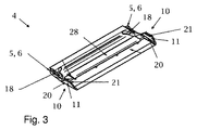
図3には、二つの側面タブ3と共にチェーンリンク1を形成し得る横断桟4が斜視図に示されている。横断桟4は、組み立てた状態においてチェーンリンク1の内側を形成し、案内される導線と対面する側の面が示されている。また、横断桟4は、枢動グループ5の要素と係合グループ10の要素も有する。枢動グループ5の要素は、接触面6によって形成され、それぞれにおいて、横断桟4の角部領域内に構成される。係合グループ10の各要素は、ばね要素20及び係合横材(engagement crosspiece)21を有する係止要素11によって形成される。凹部18は、横断桟4上の外側において、枢動グループ5と係合グループ10の要素との間に形成される。さらに、横断桟4は、その内側に、チェーンリンク1の長手方向の軸9と交差する方向に延在する桟(crosspiece)28を有する。
FIG. 3 shows a perspective view of a
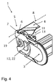
図4では、図2による側面タブ3及び図3による横断桟4を用いたチェーンリンク1の詳細を、組み立て中のある瞬間的なイメージにおいて斜視図で示している。ここで示される組み立て状態において、枢動グループ5の接触面6は、枢動グループ5の収容部7に接して設置された。それに応じて、他の接触面6(不図示)も、図示されていない側面タブ3の他の収容部7に接触するようになっていた。枢動軸8は、枢動グループ5の各要素と接触することによって構成される。続いて、横断桟4は、側面タブ3に向かって枢動軸8を中心に枢動し、そこで凸部19が凹部18内に係合し、枢動プロセスを案内する。枢動プロセスの終了時に、係止要素11及び対向軸受は、互いに係合することにより相互に作用する。さらに、桟28は、凹み13内に係合する。
In FIG. 4, the details of the
図5は、図4によって組み立てた状態を側面図で示し、下側の側面タブ4は既に組み立てられている。上側の側面タブ4は、接触面6によって収容部7に接触している。続く枢動プロセス中に、凸部19は凹部18内に係合し、それにより枢動プロセスが案内され、各側面タブ3の間の距離が設定される。枢動プロセスの終了時に、係合横材21は、係合凹部22によって形成された対向軸受12内に係合する。これに関連して、ばね要素20は、チェーンリンクの長手方向の軸9と交差する方向に、外側に向かって撓む。
FIG. 5 shows the assembled state according to FIG. 4 in a side view, with the
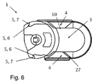
図6は、組み立てられたチェーンリンク1を側面図に概略的に示す。横断桟4及び側面タブ3は、枢動グループ5の各要素が互いに係合し、係合グループ10の各要素が互いに係合したという意味で、互いに連結された。開口スロット27は、側面タブ3と横断桟4との間に構成され、ばね要素20が外側に撓むという点で、係合グループ10の各要素の係合連結を解除するために使用できる。
FIG. 6 schematically shows the assembled
図7は、図6によって組み立てられたチェーンリンクの係合グループ10の領域における横断面の詳細を示す。横断桟4は桟28に連結され、桟28は、凹み13内に配置され、そこで特に係合により側面タブ3と連結される。さらに、係合グループ10の各要素が示されており、係合横材21を有するばね要素20は、横断桟4上に構成されている。係合横材21は、係合凹部22と係合している状態である。横断桟4を側面タブ3から外すために、ばね要素20は、係合横材21と共に外側に向かって撓むことができる。しかしながら、チェーンリンク1を完全に取り外すためには、ばね要素20を両方の側面タブにおいて同時に外側に撓ませる必要がある。
FIG. 7 shows a cross-sectional detail in the region of the
図8は、断面図における横断桟4と、プロファイル(profile)14を示す。横断桟4は、ニッチ15と、ニッチ15の縁部に上方に延在し、輪郭17を有する係合突起16とを有する。また、プロファイル14も輪郭17を有し、各係合突起16によってニッチ15内に差し込むことができ、そこで横断桟4と係合することにより連結される。連結された状態において、プロファイル14は、桟28を形成する。
FIG. 8 shows the
本発明により、複数の異なる横断桟4及び側面タブ3から簡易な方法で構築可能なチェーンリンク1が示され、ここでは、横断桟4と側面タブ3との間の連結を非意図的に外すことはできない。
According to the present invention, a
1 チェーンリンク
2 エネルギー案内チェーン
3 側面タブ
4 横断桟
5 枢動グループ
6 接触面
7 収容部
8 枢動軸
9 長手方向の軸
10 係合グループ
11 係止要素
12 対向軸受
13 凹み
14 プロファイル
15 ニッチ
16 係合突起
17 輪郭
18 凹部
19 凸部
20 ばね要素
21 係合横材
22 係合凹部
23 連結領域
24 固定した連結点
25 可動式連結点
26 外面
27 開口スロット
28 桟
DESCRIPTION OF
Claims (11)
接触面(6)と前記接触面(6)を接触させるための対応する収容部(7)とを備える二つの枢動グループ(5)と、二つの係合グループ(10)とが設けられ、前記枢動グループ(5)は、それぞれにおいて、接触した状態で前記チェーンリンク(1)の長手方向の軸(9)と交差する枢動軸(8)を形成するようにし、前記係合グループ(10)は、それぞれにおいて、係止要素(11、28)と、前記係止要素(11、28)を収容するための対応する対向軸受(12、13)とによって形成される、チェーンリンク。 A chain link (1) of an energy conducting chain (2) having two parallel side tabs (3) and at least one cross bar (4), said two side tabs (3) and said at least one The crosspieces (4) are connected to each other by being installed, pivoted and engaged,
Two pivot groups (5) comprising a contact surface (6) and a corresponding receiving part (7) for contacting said contact surface (6), and two engagement groups (10) are provided, The pivot groups (5) each form a pivot axis (8) intersecting the longitudinal axis (9) of the chain link (1) in contact with the engagement group ( 10) Chain links, each formed by a locking element (11, 28) and a corresponding counter bearing (12, 13) for receiving said locking element (11, 28).
Applications Claiming Priority (3)
| Application Number | Priority Date | Filing Date | Title |
|---|---|---|---|
| DE102011113378A DE102011113378A1 (en) | 2011-09-16 | 2011-09-16 | link |
| DE102011113378.3 | 2011-09-16 | ||
| PCT/EP2012/064950 WO2013037557A1 (en) | 2011-09-16 | 2012-07-31 | Chain link |
Publications (1)
| Publication Number | Publication Date |
|---|---|
| JP2014526659A true JP2014526659A (en) | 2014-10-06 |
Family
ID=46639479
Family Applications (1)
| Application Number | Title | Priority Date | Filing Date |
|---|---|---|---|
| JP2014530126A Pending JP2014526659A (en) | 2011-09-16 | 2012-07-31 | Chain link |
Country Status (7)
| Country | Link |
|---|---|
| US (1) | US9711959B2 (en) |
| EP (1) | EP2756207B1 (en) |
| JP (1) | JP2014526659A (en) |
| CN (1) | CN103930692B (en) |
| DE (1) | DE102011113378A1 (en) |
| IN (1) | IN2014CN02767A (en) |
| WO (1) | WO2013037557A1 (en) |
Families Citing this family (3)
| Publication number | Priority date | Publication date | Assignee | Title |
|---|---|---|---|---|
| DE202013101457U1 (en) | 2013-04-05 | 2013-04-19 | Igus Gmbh | Power supply chain |
| CN107906167A (en) * | 2017-12-22 | 2018-04-13 | 化州市新海水产有限公司 | A kind of connector |
| DE202019100434U1 (en) * | 2019-01-25 | 2019-06-03 | Igus Gmbh | Crossbar and chain link with crosspiece |
Citations (3)
| Publication number | Priority date | Publication date | Assignee | Title |
|---|---|---|---|---|
| JPH0379839A (en) * | 1990-08-10 | 1991-04-04 | Tsubakimoto Chain Co | Partition structure inside of cable drag chain |
| JP2007247716A (en) * | 2006-03-14 | 2007-09-27 | Tsubakimoto Chain Co | Cable protection and guide device |
| JP2009264480A (en) * | 2008-04-24 | 2009-11-12 | Tsubakimoto Chain Co | Cables protecting and guiding device |
Family Cites Families (9)
| Publication number | Priority date | Publication date | Assignee | Title |
|---|---|---|---|---|
| DE3522885A1 (en) * | 1985-06-26 | 1987-01-08 | Gebr Hennig Gmbh | Energy supply chain |
| DE102005061777A1 (en) * | 2005-12-23 | 2007-06-28 | Kabelschlepp Gmbh | Chain link for energy transmission chain, has transverse bar and clips arranged at distance to each other, where transverse bar is pin-jointed with one clip, and pin-joint is multi-axis pin-joint and ball-and-socket joint connection |
| JP4118306B2 (en) | 2006-03-28 | 2008-07-16 | 株式会社椿本チエイン | Cable protection guide device |
| JP4118308B2 (en) * | 2006-04-14 | 2008-07-16 | 株式会社椿本チエイン | Cable protection guide device |
| DE202006006638U1 (en) * | 2006-04-21 | 2006-06-22 | Igus Gmbh | Power supply chain |
| DE102006027246A1 (en) * | 2006-06-09 | 2007-12-20 | Flexatec Gmbh | Chain for guiding flexible energy pipes has chain links interconnected by articulated joints each with a box profile as well as plate-shaped side fish-plates and a rod-shaped transverse stay |
| DE202008008358U1 (en) | 2008-06-24 | 2008-08-21 | Kabelschlepp Gmbh | Chain link with swivel crossbar |
| DE102008060466A1 (en) * | 2008-12-05 | 2010-06-10 | Kabelschlepp Gmbh | Chain link for energy transmission chain for guiding cables and hoses between stationary and movable connection points, has transverse bar consisting of plastic that is guided by die in continuous manufacturing process of transverse bar |
| DE202009005650U1 (en) | 2009-04-17 | 2009-07-02 | Igus Gmbh | Power supply chain |
-
2011
- 2011-09-16 DE DE102011113378A patent/DE102011113378A1/en not_active Withdrawn
-
2012
- 2012-07-31 WO PCT/EP2012/064950 patent/WO2013037557A1/en active Application Filing
- 2012-07-31 IN IN2767CHN2014 patent/IN2014CN02767A/en unknown
- 2012-07-31 US US14/345,048 patent/US9711959B2/en active Active
- 2012-07-31 CN CN201280056072.7A patent/CN103930692B/en active Active
- 2012-07-31 EP EP12743953.7A patent/EP2756207B1/en active Active
- 2012-07-31 JP JP2014530126A patent/JP2014526659A/en active Pending
Patent Citations (3)
| Publication number | Priority date | Publication date | Assignee | Title |
|---|---|---|---|---|
| JPH0379839A (en) * | 1990-08-10 | 1991-04-04 | Tsubakimoto Chain Co | Partition structure inside of cable drag chain |
| JP2007247716A (en) * | 2006-03-14 | 2007-09-27 | Tsubakimoto Chain Co | Cable protection and guide device |
| JP2009264480A (en) * | 2008-04-24 | 2009-11-12 | Tsubakimoto Chain Co | Cables protecting and guiding device |
Also Published As
| Publication number | Publication date |
|---|---|
| EP2756207A1 (en) | 2014-07-23 |
| IN2014CN02767A (en) | 2015-07-03 |
| DE102011113378A1 (en) | 2013-03-21 |
| WO2013037557A1 (en) | 2013-03-21 |
| CN103930692A (en) | 2014-07-16 |
| US9711959B2 (en) | 2017-07-18 |
| EP2756207B1 (en) | 2016-01-20 |
| CN103930692B (en) | 2016-03-30 |
| US20150060609A1 (en) | 2015-03-05 |
Similar Documents
| Publication | Publication Date | Title |
|---|---|---|
| KR100933261B1 (en) | Connector, connector assembly and its connection method | |
| CN109643866B (en) | Holding frame for a plug connector and method for assembling same | |
| JP2006311785A (en) | Protector | |
| KR20140009559A (en) | Receptacle contact | |
| KR102001321B1 (en) | Holding frame and method for producing same | |
| US20100197177A1 (en) | Socket contact | |
| CN110537299B (en) | Holding frame for heavy-duty plug connectors | |
| CN102142666B (en) | Cable retainer | |
| KR20110031198A (en) | Socket contact | |
| US20170225631A1 (en) | Band clip | |
| JP2014526659A (en) | Chain link | |
| JP6247337B2 (en) | Contacts for electrical connectors | |
| JP6178182B2 (en) | Electrical junction box | |
| JP5915142B2 (en) | Electrical connector | |
| KR200467962Y1 (en) | Lever type connector assembly | |
| KR100890197B1 (en) | Circular cable chain | |
| JP2015198005A (en) | Connector and structure for fixing connector to wiring harness | |
| KR20150126378A (en) | Connection terminal and connector assembly | |
| JP2009152003A (en) | Electric wire cover | |
| JP6508914B2 (en) | Seal protection contact member with position fixing member | |
| KR101224724B1 (en) | Female connector terminal | |
| US10230190B2 (en) | Contact terminal assembled from at least two parts | |
| JP6029089B2 (en) | Electrical junction box | |
| KR101346703B1 (en) | Connector | |
| KR101828041B1 (en) | Junction box for optical cable |
Legal Events
| Date | Code | Title | Description |
|---|---|---|---|
| A621 | Written request for application examination |
Free format text: JAPANESE INTERMEDIATE CODE: A621 Effective date: 20140612 |
|
| A977 | Report on retrieval |
Free format text: JAPANESE INTERMEDIATE CODE: A971007 Effective date: 20150408 |
|
| A131 | Notification of reasons for refusal |
Free format text: JAPANESE INTERMEDIATE CODE: A131 Effective date: 20150414 |
|
| A601 | Written request for extension of time |
Free format text: JAPANESE INTERMEDIATE CODE: A601 Effective date: 20150707 |
|
| A521 | Written amendment |
Free format text: JAPANESE INTERMEDIATE CODE: A523 Effective date: 20150730 |
|
| A02 | Decision of refusal |
Free format text: JAPANESE INTERMEDIATE CODE: A02 Effective date: 20160105 |