JP2014518713A - Wireless ultrasonic personal health monitoring system - Google Patents
Wireless ultrasonic personal health monitoring system Download PDFInfo
- Publication number
- JP2014518713A JP2014518713A JP2014511335A JP2014511335A JP2014518713A JP 2014518713 A JP2014518713 A JP 2014518713A JP 2014511335 A JP2014511335 A JP 2014511335A JP 2014511335 A JP2014511335 A JP 2014511335A JP 2014518713 A JP2014518713 A JP 2014518713A
- Authority
- JP
- Japan
- Prior art keywords
- signal
- ecg
- computing devices
- output
- ultrasonic
- Prior art date
- Legal status (The legal status is an assumption and is not a legal conclusion. Google has not performed a legal analysis and makes no representation as to the accuracy of the status listed.)
- Pending
Links
Images


Classifications
-
- A—HUMAN NECESSITIES
- A61—MEDICAL OR VETERINARY SCIENCE; HYGIENE
- A61B—DIAGNOSIS; SURGERY; IDENTIFICATION
- A61B5/00—Measuring for diagnostic purposes; Identification of persons
- A61B5/68—Arrangements of detecting, measuring or recording means, e.g. sensors, in relation to patient
- A61B5/6887—Arrangements of detecting, measuring or recording means, e.g. sensors, in relation to patient mounted on external non-worn devices, e.g. non-medical devices
- A61B5/6898—Portable consumer electronic devices, e.g. music players, telephones, tablet computers
-
- A—HUMAN NECESSITIES
- A61—MEDICAL OR VETERINARY SCIENCE; HYGIENE
- A61B—DIAGNOSIS; SURGERY; IDENTIFICATION
- A61B5/00—Measuring for diagnostic purposes; Identification of persons
- A61B5/0002—Remote monitoring of patients using telemetry, e.g. transmission of vital signals via a communication network
- A61B5/0015—Remote monitoring of patients using telemetry, e.g. transmission of vital signals via a communication network characterised by features of the telemetry system
- A61B5/0022—Monitoring a patient using a global network, e.g. telephone networks, internet
-
- G—PHYSICS
- G16—INFORMATION AND COMMUNICATION TECHNOLOGY [ICT] SPECIALLY ADAPTED FOR SPECIFIC APPLICATION FIELDS
- G16H—HEALTHCARE INFORMATICS, i.e. INFORMATION AND COMMUNICATION TECHNOLOGY [ICT] SPECIALLY ADAPTED FOR THE HANDLING OR PROCESSING OF MEDICAL OR HEALTHCARE DATA
- G16H40/00—ICT specially adapted for the management or administration of healthcare resources or facilities; ICT specially adapted for the management or operation of medical equipment or devices
- G16H40/60—ICT specially adapted for the management or administration of healthcare resources or facilities; ICT specially adapted for the management or operation of medical equipment or devices for the operation of medical equipment or devices
- G16H40/63—ICT specially adapted for the management or administration of healthcare resources or facilities; ICT specially adapted for the management or operation of medical equipment or devices for the operation of medical equipment or devices for local operation
-
- G—PHYSICS
- G16—INFORMATION AND COMMUNICATION TECHNOLOGY [ICT] SPECIALLY ADAPTED FOR SPECIFIC APPLICATION FIELDS
- G16H—HEALTHCARE INFORMATICS, i.e. INFORMATION AND COMMUNICATION TECHNOLOGY [ICT] SPECIALLY ADAPTED FOR THE HANDLING OR PROCESSING OF MEDICAL OR HEALTHCARE DATA
- G16H40/00—ICT specially adapted for the management or administration of healthcare resources or facilities; ICT specially adapted for the management or operation of medical equipment or devices
- G16H40/60—ICT specially adapted for the management or administration of healthcare resources or facilities; ICT specially adapted for the management or operation of medical equipment or devices for the operation of medical equipment or devices
- G16H40/67—ICT specially adapted for the management or administration of healthcare resources or facilities; ICT specially adapted for the management or operation of medical equipment or devices for the operation of medical equipment or devices for remote operation
-
- H—ELECTRICITY
- H04—ELECTRIC COMMUNICATION TECHNIQUE
- H04B—TRANSMISSION
- H04B11/00—Transmission systems employing sonic, ultrasonic or infrasonic waves
-
- H—ELECTRICITY
- H04—ELECTRIC COMMUNICATION TECHNIQUE
- H04M—TELEPHONIC COMMUNICATION
- H04M1/00—Substation equipment, e.g. for use by subscribers
- H04M1/02—Constructional features of telephone sets
- H04M1/0202—Portable telephone sets, e.g. cordless phones, mobile phones or bar type handsets
- H04M1/0254—Portable telephone sets, e.g. cordless phones, mobile phones or bar type handsets comprising one or a plurality of mechanically detachable modules
-
- H—ELECTRICITY
- H04—ELECTRIC COMMUNICATION TECHNIQUE
- H04M—TELEPHONIC COMMUNICATION
- H04M1/00—Substation equipment, e.g. for use by subscribers
- H04M1/72—Mobile telephones; Cordless telephones, i.e. devices for establishing wireless links to base stations without route selection
- H04M1/724—User interfaces specially adapted for cordless or mobile telephones
- H04M1/72448—User interfaces specially adapted for cordless or mobile telephones with means for adapting the functionality of the device according to specific conditions
- H04M1/7246—User interfaces specially adapted for cordless or mobile telephones with means for adapting the functionality of the device according to specific conditions by connection of exchangeable housing parts
-
- A—HUMAN NECESSITIES
- A61—MEDICAL OR VETERINARY SCIENCE; HYGIENE
- A61B—DIAGNOSIS; SURGERY; IDENTIFICATION
- A61B5/00—Measuring for diagnostic purposes; Identification of persons
- A61B5/0002—Remote monitoring of patients using telemetry, e.g. transmission of vital signals via a communication network
- A61B5/0004—Remote monitoring of patients using telemetry, e.g. transmission of vital signals via a communication network characterised by the type of physiological signal transmitted
- A61B5/0006—ECG or EEG signals
-
- A—HUMAN NECESSITIES
- A61—MEDICAL OR VETERINARY SCIENCE; HYGIENE
- A61B—DIAGNOSIS; SURGERY; IDENTIFICATION
- A61B5/00—Measuring for diagnostic purposes; Identification of persons
- A61B5/0002—Remote monitoring of patients using telemetry, e.g. transmission of vital signals via a communication network
- A61B5/0015—Remote monitoring of patients using telemetry, e.g. transmission of vital signals via a communication network characterised by features of the telemetry system
-
- A—HUMAN NECESSITIES
- A61—MEDICAL OR VETERINARY SCIENCE; HYGIENE
- A61B—DIAGNOSIS; SURGERY; IDENTIFICATION
- A61B5/00—Measuring for diagnostic purposes; Identification of persons
- A61B5/0002—Remote monitoring of patients using telemetry, e.g. transmission of vital signals via a communication network
- A61B5/0026—Remote monitoring of patients using telemetry, e.g. transmission of vital signals via a communication network characterised by the transmission medium
-
- A—HUMAN NECESSITIES
- A61—MEDICAL OR VETERINARY SCIENCE; HYGIENE
- A61B—DIAGNOSIS; SURGERY; IDENTIFICATION
- A61B5/00—Measuring for diagnostic purposes; Identification of persons
- A61B5/02—Detecting, measuring or recording pulse, heart rate, blood pressure or blood flow; Combined pulse/heart-rate/blood pressure determination; Evaluating a cardiovascular condition not otherwise provided for, e.g. using combinations of techniques provided for in this group with electrocardiography or electroauscultation; Heart catheters for measuring blood pressure
- A61B5/0205—Simultaneously evaluating both cardiovascular conditions and different types of body conditions, e.g. heart and respiratory condition
-
- A—HUMAN NECESSITIES
- A61—MEDICAL OR VETERINARY SCIENCE; HYGIENE
- A61B—DIAGNOSIS; SURGERY; IDENTIFICATION
- A61B5/00—Measuring for diagnostic purposes; Identification of persons
- A61B5/24—Detecting, measuring or recording bioelectric or biomagnetic signals of the body or parts thereof
- A61B5/316—Modalities, i.e. specific diagnostic methods
- A61B5/318—Heart-related electrical modalities, e.g. electrocardiography [ECG]
- A61B5/332—Portable devices specially adapted therefor
-
- H—ELECTRICITY
- H04—ELECTRIC COMMUNICATION TECHNIQUE
- H04M—TELEPHONIC COMMUNICATION
- H04M2250/00—Details of telephonic subscriber devices
- H04M2250/12—Details of telephonic subscriber devices including a sensor for measuring a physical value, e.g. temperature or motion
Abstract
パーソナルモニタリングデバイスは、ユーザの皮膚に接触すると生理的信号を検知するように構成されるセンサアセンブリを有する。センサアセンブリは、検知された生理的信号を示す電気信号を生成する。センサアセンブリと統合されかつセンサアセンブリに電気接続された変換器アセンブリは、センサアセンブリによって生成される電気信号を、周波数変調非可聴超音波音信号に変換する。超音波信号は、アンダーサンプリングすることによって生成されるエイリアシングされた信号から復調される。 The personal monitoring device has a sensor assembly configured to detect a physiological signal upon contact with a user's skin. The sensor assembly generates an electrical signal that is indicative of the sensed physiological signal. A transducer assembly integrated with and electrically connected to the sensor assembly converts the electrical signal generated by the sensor assembly into a frequency modulated non-audible ultrasonic sound signal. The ultrasound signal is demodulated from the aliased signal generated by undersampling.
Description
現在特許請求され開示される本発明の概念は、一般に、パーソナル生理機能モニタリングデバイスおよび方法に関し、より詳細には、制限としてではないが、スマートフォンなどのコンピューティングデバイスを利用してECG、心拍数、および心臓不整脈モニタリングを提供するためのデバイス、システム、およびソフトウェアに関する。 The presently claimed and disclosed concepts generally relate to personal physiology monitoring devices and methods, and more particularly, but not as a limitation, using a computing device such as a smartphone to provide ECG, heart rate, And devices, systems, and software for providing cardiac arrhythmia monitoring.
従来技術は、ECGデータまたは同様なものが、監視されかつ/または患者から特定の医師のオフィスまたはヘルスサービスセンタへ送信される多数のシステムを含む。たとえば、米国特許第5,735,285号は、患者のECG信号を周波数変調オーディオ信号に変換する手持ち式デバイスの使用を開示しており、そのオーディオ信号は、次に、選択された手持ち式コンピュータデバイスまたは指定された医師のオフィスに電話システムを介してオーディオ入力することによって解析される。同様に、米国特許第6,264,614号は、心臓モニタを開示しており、その心臓モニタは、心拍動などの生物学的機能を検知し、可聴信号をコンピュータマイクロフォンに出力するために患者によって操作される。コンピュータは、可聴信号を処理し、ネットワークまたはインターネットを通じて、結果として得られるデータ信号を送出する。米国特許第6,685,633号は、患者が自分の胸部に接して保持しうる心臓モニタを開示する。デバイスは、心臓の拍動などの機能または状態に応答する可聴信号を、コンピュータに接続されたマイクロフォンに出力する。これらのオーディオ送信のそれぞれは、可聴音の送信に限定される。換言すれば、人間が聞き取れる周波数を超えるキャリア周波数、すなわち17kHzを超える周波数における周波数変調音送信は企図されてはいなかった。 The prior art includes numerous systems where ECG data or the like is monitored and / or transmitted from the patient to a particular physician office or health service center. For example, U.S. Pat. Analyzed by audio input through a telephone system to a doctor's office. Similarly, US Pat. No. 6,264,614 discloses a cardiac monitor that is operated by a patient to sense biological functions such as heartbeat and output an audible signal to a computer microphone. . The computer processes the audible signal and sends the resulting data signal over a network or the Internet. U.S. Pat. No. 6,685,633 discloses a cardiac monitor that a patient can hold against his chest. The device outputs an audible signal responsive to a function or condition, such as a heart beat, to a microphone connected to the computer. Each of these audio transmissions is limited to the transmission of audible sounds. In other words, frequency-modulated sound transmission at a carrier frequency exceeding the frequency that humans can hear, that is, a frequency exceeding 17 kHz has not been intended.
米国特許出願公開第2004/0220487号は、結合され振幅変調されるECG電極信号を検知するECG電極を有するシステムを開示する。複合信号は、コンピューティングデバイス内の音ポートに有線または無線で送信される。19kHz〜21kHzの通過帯域を有するデジタルバンドパスフィルタが考慮される。しかし、商業的に利用可能なコンピューティングデバイスを使用して、この周波数範囲における復調手段は考慮されていない。さらに、送信を行うための音波の使用は企図されていない。 US Patent Application Publication No. 2004/0220487 discloses a system having an ECG electrode that senses a combined and amplitude modulated ECG electrode signal. The composite signal is transmitted in a wired or wireless manner to a sound port in the computing device. A digital bandpass filter having a passband of 19 kHz to 21 kHz is considered. However, using commercially available computing devices, demodulation means in this frequency range are not considered. In addition, the use of sound waves to transmit is not contemplated.
米国特許出願公開第2010/0113950号は、ユーザの心臓信号を検出するためのいくつかの誘導線を含む心臓センサを有する電子デバイスを開示する。誘導線は、センサを視野から隠すために、電子デバイスハウジングの内部表面に結合される。検出された信号を使用して、電子デバイスは、ユーザを識別または認証しうる。 US Patent Application Publication No. 2010/0113950 discloses an electronic device having a heart sensor that includes a number of guide wires for detecting a user's heart signal. A guide wire is coupled to the inner surface of the electronic device housing to hide the sensor from view. Using the detected signal, the electronic device may identify or authenticate the user.
米国特許第6,820,057号は、ECGデータを取得し、記録し、送信するシステムを開示しており、ECG信号は、可聴範囲内のキャリアトーンを有する周波数変調オーディオトーンにおいてエンコードされる。しかし、約3kHzを超えるキャリア周波数が実際に考慮されず、可聴周波数を超えるキャリア周波数が考慮されず、より高いキャリア周波数における復調方法が考慮されていない。 US Pat. No. 6,820,057 discloses a system for acquiring, recording and transmitting ECG data, wherein the ECG signal is encoded in a frequency modulated audio tone having a carrier tone in the audible range. However, a carrier frequency exceeding about 3 kHz is not actually considered, a carrier frequency exceeding an audible frequency is not considered, and a demodulation method at a higher carrier frequency is not considered.
電話伝送信号および可聴音響信号を利用する従来技術の制限は、近傍における話または任意の他の騒々しい活動によって減じられ、したがって、心臓モニタリングデータ信号の完全性をおそらくは脅かす信号対雑音比を含む。さらに、可聴信号は、コンピュータおよび心臓モニタの近傍の誰にでも聞き取ることができ、ユーザならびに近傍の他の人にとってやっかいである可能性がある。他のアプリケーションは、スマートフォンなどの既存のコンピューティングデバイスと容易に適合する、信頼性があり費用がかからないパーソナルモニタリングデバイスを提供することができない。これらの問題が、リアルタイムの生理的データを送信するパーソナルモニタリングデバイスにおいて対処される場合、有利である。 Prior art limitations utilizing telephone transmission signals and audible acoustic signals are reduced by nearby talk or any other noisy activity, and thus include a signal-to-noise ratio that probably threatens the integrity of the cardiac monitoring data signal . In addition, the audible signal can be heard by anyone in the vicinity of the computer and the heart monitor and can be troublesome for the user and others in the vicinity. Other applications cannot provide a reliable and inexpensive personal monitoring device that is easily compatible with existing computing devices such as smartphones. It is advantageous if these issues are addressed in personal monitoring devices that transmit real-time physiological data.
ここに請求され開示される本発明の実施形態は、ユーザの皮膚に接触すると生理的信号を検知するように構成されるセンサアセンブリを有するパーソナルモニタリングデバイスを対象とする。センサアセンブリは、検知された生理的信号を示す電気信号を生成する。オーディオ送信機を含む変換器アセンブリは、センサアセンブリと統合されかつセンサアセンブリに電気接続される。変換器アセンブリは、センサアセンブリによって生成される電気信号を受信し、これらの信号を、オーディオ送信機を通してコンピューティングデバイス内のマイクロフォンに出力する。信号は、非可聴超音波周波数変調音信号として出力される。 Embodiments of the invention claimed and disclosed herein are directed to personal monitoring devices having a sensor assembly configured to sense a physiological signal upon contact with a user's skin. The sensor assembly generates an electrical signal that is indicative of the sensed physiological signal. A transducer assembly including an audio transmitter is integrated with and electrically connected to the sensor assembly. The transducer assembly receives the electrical signals generated by the sensor assembly and outputs these signals through an audio transmitter to a microphone in the computing device. The signal is output as a non-audible ultrasonic frequency modulated sound signal.
ここに請求され開示される本発明の概念のECGデバイスは、ユーザの皮膚に接触すると心臓関連信号を検知し、検知された心臓関連信号をECG電気信号に変換するように構成される電極アセンブリを含む。電極アセンブリと統合されかつ電極アセンブリに電気接続された変換器アセンブリは、前記アセンブリによって生成されるECG電気信号を受信し、ECG音信号をオーディオ送信機の範囲内でオーディオ送信機を通してコンピューティングデバイス内のマイクロフォンに出力するように構成される。変換器アセンブリは、ECG信号を、超音波FM音信号として出力するようにさらに構成される。 The ECG device of the inventive concept claimed and disclosed herein comprises an electrode assembly configured to detect a heart related signal upon contact with a user's skin and convert the detected heart related signal into an ECG electrical signal. Including. A transducer assembly integrated with and electrically connected to the electrode assembly receives the ECG electrical signal generated by the assembly and passes the ECG sound signal through the audio transmitter within the audio transmitter within the computing device. Configured to output to a microphone. The transducer assembly is further configured to output the ECG signal as an ultrasonic FM sound signal.
一実施形態では、ECGデバイスとして使用可能なスマートフォン保護ケースが提供される。ユーザの皮膚に接触すると心臓関連信号を検知し、検知された心臓関連信号をECG電気信号に変換するように構成される電極アセンブリが設けられる。電極アセンブリと統合されかつ電極アセンブリに電気接続された変換器アセンブリは、電極アセンブリによって生成されるECG電気信号を約18kHz〜約24kHzの範囲のキャリア周波数を有する超音波周波数変調ECG音信号に変換するように構成され、オーディオ送信機を通して、スマートフォン保護ケース内に配置されたスマートフォンによって受信されることが可能な信号強度で超音波周波数変調音信号を出力するようにさらに構成される。 In one embodiment, a smartphone protective case that can be used as an ECG device is provided. An electrode assembly is provided that is configured to detect a heart related signal upon contact with the user's skin and convert the detected heart related signal into an ECG electrical signal. A transducer assembly integrated with and electrically connected to the electrode assembly converts the ECG electrical signal generated by the electrode assembly into an ultrasonic frequency modulated ECG sound signal having a carrier frequency in the range of about 18 kHz to about 24 kHz. And configured to output an ultrasonic frequency modulated sound signal through the audio transmitter with a signal strength that can be received by a smartphone disposed in the smartphone protection case.
第2の実施形態では、医療データを生成し転送するためのシステムが提供される。システムは、ユーザの皮膚に接触すると心臓関連信号を検知し、検知された心臓関連信号をECG電気信号に変換するように構成される電極アセンブリを含む。オーディオ送信機を含む変換器アセンブリは、電極アセンブリと統合されかつ電極アセンブリに電気接続され、また、ECG電気信号を超音波FM音信号に変換するように構成される。超音波FM音信号は、オーディオ送信機を通してコンピューティングデバイス内のマイクロフォンに出力される。コンピューティングデバイスのアナログ-デジタル変換器(ADC)は、マイクロフォンからの信号をサンプリングし、信号をデジタルオーディオ信号に変換するように構成される。非一時的コンピュータ可読媒体上に記憶され、コンピューティングデバイスによって実行可能な復調ソフトウェアは、コンピューティングデバイスが、(1)デジタル化されたオーディオ信号をアンダーサンプリングし、デジタル化されたオーディオ信号を低周波帯域になるようエイリアシングし、(2)エイリアシングされたデジタルFMオーディオ信号を低周波帯域で復調して、ECG出力を生成するようにさせる。 In a second embodiment, a system for generating and transferring medical data is provided. The system includes an electrode assembly configured to detect a heart related signal upon contact with the user's skin and convert the detected heart related signal into an ECG electrical signal. A transducer assembly including an audio transmitter is integrated with and electrically connected to the electrode assembly and is configured to convert an ECG electrical signal to an ultrasonic FM sound signal. The ultrasonic FM sound signal is output to the microphone in the computing device through the audio transmitter. The analog-to-digital converter (ADC) of the computing device is configured to sample the signal from the microphone and convert the signal to a digital audio signal. Demodulation software stored on a non-transitory computer readable medium and executable by a computing device allows the computing device to (1) undersample the digitized audio signal and (2) The aliased digital FM audio signal is demodulated in a low frequency band to generate an ECG output.
別の実施形態では、1つまたは複数のコンピューティングデバイスによって実行されることが可能な命令のセットを記憶するための非一時的コンピュータ可読記憶媒体が提供され、命令のセットは、1つまたは複数のコンピューティングデバイスによって実行されると、1つまたは複数のコンピューティングデバイスが約18kHz〜約24kHzの範囲のキャリア周波数を有するデジタル化されたFMオーディオ信号を、少なくとも、(1)デジタル化されたFMオーディオ信号をアンダーサンプリングし、それにより、デジタル化されたFMオーディオ信号を低周波帯域になるようエイリアシングすること、および、(2)エイリアシングされたデジタルFMオーディオ信号を低周波帯域で復調して、ECG出力を生成することによって、復調するようにさせる。 In another embodiment, a non-transitory computer readable storage medium is provided for storing a set of instructions that can be executed by one or more computing devices, wherein the set of instructions is one or more. When executed by a computing device, at least one digitized FM audio signal having a carrier frequency in the range of about 18 kHz to about 24 kHz, at least (1) the digitized FM Undersampling the audio signal, thereby aliasing the digitized FM audio signal to the low frequency band, and (2) demodulating the aliased digital FM audio signal in the low frequency band to produce an ECG Produce demodulation by generating output.
ヘルスモニタリングのための方法が提供され、以下のステップを含む。ECGデバイスの電極アセンブリが、ユーザの皮膚に接触状態で設置される。電極アセンブリは、ユーザの心臓関連信号を検知し、検知された心臓関連信号をECG電気信号に変換するように構成される。オーディオ送信機を含む変換器アセンブリは、センサアセンブリと統合されかつセンサアセンブリに電気接続され、また、前記センサによって生成されるECG電気信号を受信し、オーディオ送信機を通してECG音信号を超音波FM音信号として出力するように構成される。超音波FM信号は、オーディオ送信機を通して出力され、オーディオ送信機の範囲内で、コンピューティングデバイス内のマイクロフォンで受信され、復調され、結果として得られるECG出力が記録される。任意選択で、ユーザは、ECG出力と同時に、話された音声メッセージを記録することができる。 A method for health monitoring is provided and includes the following steps. The electrode assembly of the ECG device is placed in contact with the user's skin. The electrode assembly is configured to sense a user's heart related signal and convert the sensed heart related signal into an ECG electrical signal. A transducer assembly including an audio transmitter is integrated with and electrically connected to the sensor assembly, receives an ECG electrical signal generated by the sensor, and converts the ECG sound signal through the audio transmitter into an ultrasonic FM sound. It is configured to output as a signal. The ultrasonic FM signal is output through an audio transmitter, received within a range of the audio transmitter, received by a microphone in the computing device, demodulated, and the resulting ECG output is recorded. Optionally, the user can record the spoken voice message simultaneously with the ECG output.
したがって、(1)当技術分野で知られている技術、(2)目下請求され開示される本発明の概念の先に参照された一般的な説明、および(3)以下に続く本発明の詳細な説明を利用して、目下請求され開示される本発明の概念の利点および新規性が、当業者に容易に明らかになるであろう。 Accordingly, (1) techniques known in the art, (2) a general description referenced above of the presently claimed and disclosed concepts of the invention, and (3) details of the invention that follow. The advantages and novelty of the inventive concept presently claimed and disclosed will be readily apparent to those skilled in the art using this description.
本発明の少なくとも1つの実施形態を詳細に説明する前に、本発明が、以下の説明で述べられる、構造の詳細、実験、例示的なデータ、および/またはコンポーネントの配置構成に、その適用を限定されないことが理解される。本発明は、他の実施形態が可能である、または、種々の方法で実施または実行されることが可能である。同様に、本明細書で使用される用語は、説明のためのものであり、制限的であるとみなされるべきでないことが理解される。 Before describing at least one embodiment of the present invention in detail, the present invention may be applied to structural details, experiments, exemplary data, and / or component arrangements as described in the following description. It is understood that it is not limited. The invention is capable of other embodiments or of being practiced or carried out in various ways. Similarly, it is understood that the terminology used herein is for the purpose of description and should not be considered limiting.
本開示の実施形態の以下の詳細な説明では、本開示のより完全な理解を可能にするために、多数の特定の詳細が述べられる。しかし、本開示内の概念が、これらの特定の詳細なしで実施されうることが当業者に明らかである。他の事例では、よく知られている特徴は、説明を不必要に複雑することを回避するために詳細に述べられていない。 In the following detailed description of embodiments of the present disclosure, numerous specific details are set forth in order to provide a more thorough understanding of the present disclosure. However, it will be apparent to one skilled in the art that the concepts within this disclosure may be practiced without these specific details. In other instances, well-known features have not been described in detail in order to avoid unnecessarily complicating the description.
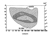
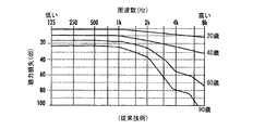
人間の聴覚範囲は、20Hz〜20kHzと言われることが多い。理想的な実験室条件下での子供の最大聴覚範囲は、実際には、12Hz程度の低い値と20Hz程度の高い値である。しかし、図1に示すように、閾値周波数、すなわち、検出可能な最小強度は、10kHzと20kHzとの間の痛覚閾値まで急速に上昇する。そのため、約16kHzを超える音は、聞き取るためにかなり強くなければならない。ほぼ誕生直後に、これらのより高い周波数についての閾値音レベルは増加する。図2に示すように、平均的な20歳は、8kHz範囲内で約10dBを喪失し、一方、年齢90で、平均的な人は、この周波数で100dBを超えて喪失した。
The human hearing range is often said to be 20Hz-20kHz. The child's maximum hearing range under ideal laboratory conditions is actually as low as 12Hz and as high as 20Hz. However, as shown in FIG. 1, the threshold frequency, ie the minimum detectable intensity, rapidly rises to a pain threshold between 10 kHz and 20 kHz. Therefore, sounds above about 16kHz must be fairly strong to hear. Almost immediately after birth, the threshold sound level for these higher frequencies increases. As shown in FIG. 2, the average 20-year-old lost approximately 10 dB in the 8 kHz range, while at
非常に高い周波数の音を使用する例示的な製品は、蚊アラームであり、意図的に困惑させる17.4kHzアラームを放出し、若い人々がぶらつくのを思いとどまらせるために使用される物議をかもすデバイスである。この周波数における成人の聴力損失のせいで、このアラームは、通常、年齢25歳未満の人々によって聞き取られるだけである。同様に、学生は、学校にいる間に自分の携帯電話上で15〜17kHzの「モスキート(mosquito)」リングトーンを使用することによって、成人の聴力損失を利用する。学生は、「モスキート」リングトーンを聞き取ることができ、一方、学生の成人教師は、聞き取ることができない。用語「超音波(ultrasonic)」は、通常、人間によって知覚される範囲を超えることを意味する。しかし、立証されるように、聴覚周波数の上限は、個人によって、また、一般に年齢と共に変化する。この上限の差のために、用語「超音波」は、「17kHz以上の音周波数(sound frequencies of 17 kHz or greater)」を指すように、本明細書でまたは特許請求の範囲で定義される。 An example product that uses very high frequency sounds is a mosquito alarm, a deliberately confusing 17.4kHz alarm that emits a controversial device used to discourage young people from wandering It is. Due to adult hearing loss at this frequency, this alarm is usually only heard by people under the age of 25 years. Similarly, students take advantage of adult hearing loss by using a 15-17 kHz “mosquito” ring tone on their mobile phone while at school. The student can hear the “mosquito” ring tone, while the student's adult teacher cannot. The term “ultrasonic” means beyond what is normally perceived by humans. However, as evidenced, the upper limit of the auditory frequency varies from individual to individual and generally with age. Because of this upper limit difference, the term “ultrasound” is defined herein or in the claims to refer to “sound frequencies of 17 kHz or greater”.
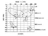
しかし、興味深いことには、約10kHzを超える周囲音または雑音はほんのわずかしか存在しない。図3を参照すると、ほとんどの日常の音は、約4kHz未満の周波数で起こる。そのため、超音波範囲内の信号の使用は、周りの人々にとって無音であるだけでなく、非常に望ましい信号対雑音比(SNR)を提供する。 Interestingly, however, there is very little ambient or noise above about 10 kHz. Referring to FIG. 3, most everyday sounds occur at frequencies below about 4 kHz. Thus, the use of signals within the ultrasound range is not only silent for the people around but also provides a very desirable signal-to-noise ratio (SNR).
音響エンジニアは、約20kHzを超える任意の周波数が、知覚される音に全く影響を及ぼさないと考えても差し支えなく、音響エンジニアは、この範囲を超える全てをフィルタリングする。20kHz未満であるが、依然として超音波範囲内にある音は、ほとんど問題なく、標準的なサンプリングプロシージャが、相応して確立された。アナログ信号をサンプリングすることは、無線信号であれ、可聴音信号であれ、fs/2>fであるようなサンプリング周波数fsを必要とし、ここで、fは正弦波周波数であることが一般に理解される。この理由で、音システムは、20kHz音上限について40kHzの計算されたナイキストシャノンのサンプリングレートより多少高く設定された44.1kHzの現在の標準的なサンプリングレートで音をサンプリングするように設計される。既存の復調プロシージャ、コンピュータ、電話、携帯電話、ステレオ音システムなどを使用する、超音波範囲内のFM狭帯域信号の実際の復調は、オリジナル信号の非常に不十分な再生をもたらすことになる。先に論じたように、これらの高い周波数において自然の「雑音(noise)」が非常に少ないことによって、超音波範囲内のキャリア信号が非常に低い信号対雑音比を有するため、これは不運である。 The acoustic engineer may think that any frequency above about 20 kHz has no effect on the perceived sound, and the acoustic engineer filters everything beyond this range. Sounds below 20 kHz, but still in the ultrasonic range, had little problem and a standard sampling procedure was established accordingly. Sampling an analog signal, whether wireless or audible, requires a sampling frequency f s such that f s / 2> f, where f is generally a sinusoidal frequency. Understood. For this reason, the sound system is designed to sample the sound at the current standard sampling rate of 44.1 kHz, set slightly higher than the calculated Nyquist Shannon sampling rate of 40 kHz for the 20 kHz sound limit. The actual demodulation of FM narrowband signals in the ultrasonic range, using existing demodulation procedures, computers, telephones, cell phones, stereo sound systems, etc. will result in very poor reproduction of the original signal. As discussed earlier, this is unfortunate because the carrier signal in the ultrasound range has a very low signal-to-noise ratio due to the very low natural "noise" at these high frequencies. is there.
本明細書で開示される本発明の概念は、生理的信号を測定し、これらの測定値を、従来の電話伝送法と比較してずっと改善された信号対雑音比を有する周波数変調超音波信号を使用して無線でかつ音もなく送信するためのパーソナルモニタリングデバイス、方法、およびシステムを対象とする。超音波信号を受信し、既存のコンピュータおよびスマートフォン技術を使用して優れた精度で復調する方法およびアルゴリズムもまた提供される。 The inventive concepts disclosed herein measure frequency-modulated ultrasound signals having a much improved signal-to-noise ratio compared to conventional telephone transmission methods by measuring physiological signals. Intended for personal monitoring devices, methods and systems for transmitting wirelessly and without sound. Methods and algorithms are also provided for receiving ultrasound signals and demodulating with good accuracy using existing computer and smartphone technology.
ここに請求され開示される本発明の概念は、パーソナルモニタリングデバイス10を提供し、その実施形態が、図4および図5に概略的に示される。モニタリングデバイス10の取得エレクトロニクス11は、ユーザの皮膚に接触すると生理的信号を検知するように構成されるセンサアセンブリ12を含む。センサアセンブリ12は、検知された生理的信号を示す電気信号を生成し、その信号は、センサアセンブリ12と統合された変換器アセンブリ14に入力される。変換器アセンブリ14は、センサアセンブリ12によって生成される電気信号を周波数変調超音波信号に変換し、その信号は、超音波送信機24によって出力される。一実施形態では、周波数変調超音波信号は、約18kHz〜約24kHzの範囲のキャリア周波数を有する。別の実施形態では、周波数変調超音波信号は、約20kHz〜約24kHzの範囲のキャリア周波数を有する。
The inventive concept as claimed and disclosed herein provides a
センサアセンブリ12は、ユーザが監視したいと欲する生理的信号を検出するように働く任意の適したセンサを含みうる。こうした生理的信号の非制限的な例は、呼吸、心拍動、心拍数、心電図(electrocardiogram)(ECG)、筋電図(electromyogram)(EMG)、眼電図(electrooculogram)(EOG)、パルスオキシメトリ、フォトプレチスモグラム(PPG)、および脳波(electroencephalogram)(EEG)を含むが、それに限定されない。 The sensor assembly 12 may include any suitable sensor that serves to detect a physiological signal that the user desires to monitor. Non-limiting examples of such physiological signals include breathing, heart rate, heart rate, electrocardiogram (ECG), electromyogram (EMG), electrooculogram (EOG), pulse oxy Includes but is not limited to metrics, photoplethysmogram (PPG), and electroencephalogram (EEG).
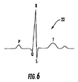
呼吸検出器は、従来のマイクロフォン補助聴診器12'でありうる。心拍動および心拍数は、同様に従来のマイクロフォン補助聴診器12'を使用して、または、心臓によって生成される電気信号を経時的に検知する電極アセンブリ18を使用することによって検出されうる。こうした電極18はまた、心電図検査(electrocardiography)(ECG)のために心臓の電気活動を経時的に検出するために使用されうる。ECGは、それぞれの心拍動中に心筋が脱分極するときに生成される皮膚上の小さな電気的変化の測定結果である。一対の電極18からの出力は誘導線20として知られている。心臓の両側に設置される2つの電極間の電圧の小さな上昇および降下が処理されて、図6に示す例示的なECGなどのグラフィカルなECG表現22が生成されうる。
The respiration detector can be a conventional microphone-assisted stethoscope 12 '. Heart rate and heart rate can be detected using a conventional microphone-assisted stethoscope 12 'as well, or by using an
筋電図検査(electromyography)(EMG)は、細胞が電気的にまたは神経学的に活性化されるときに筋肉細胞によって生成される電位を検出する。信号は、医療的異常を検出するために解析されうる。眼電図検査(electrooculography)(EOG)は、網膜の安静時電位を測定するための技法である。通常、一対の電極18は、眼の上と下、または、眼の左と右に設置され、電位差測定は、眼の位置についての尺度である。
Electromyography (EMG) detects the potential generated by muscle cells when the cells are activated electrically or neurologically. The signal can be analyzed to detect a medical anomaly. Electrooculography (EOG) is a technique for measuring the resting potential of the retina. Typically, a pair of
人のヘモグロビンの酸素化は、血液サンプルから直接測定するのではなく、パルスオキシメトリセンサを使用して無侵襲的方法で間接的に監視されうる。センサは、指先または耳たぶなどの人の身体の薄い部分上に設置され、赤波長と赤外線波長の両方を含む光が、一方の側から他方の側に通される。2つの波長のそれぞれの吸収の変化が測定され、その差が、人の血液の酸素飽和度および皮膚内の血液容積の変化を推定するために使用される。フォトプレチスモグラム(PPG)は、その後、パルスオキシメータセンサを使用して、または、単一光源を使用する光学センサによって得られうる。PPGは、血流および心拍数を測定するために使用されうる。脳波(EEG)は、頭皮に取付けられた電極を使用して監視され、脳活動によって生成される電圧を測定しうる。 Human hemoglobin oxygenation can be monitored indirectly in a non-invasive manner using pulse oximetry sensors rather than directly from blood samples. The sensor is placed on a thin part of a person's body, such as a fingertip or earlobe, and light containing both red and infrared wavelengths is passed from one side to the other. The change in absorption at each of the two wavelengths is measured and the difference is used to estimate the change in blood oxygen saturation and blood volume in the skin of the person. A photoplethysmogram (PPG) can then be obtained using a pulse oximeter sensor or by an optical sensor using a single light source. PPG can be used to measure blood flow and heart rate. An electroencephalogram (EEG) can be monitored using electrodes attached to the scalp to measure the voltage generated by brain activity.
変換器アセンブリ14は、センサアセンブリ12によって生成される電気信号を、コンピューティングデバイス16によって受信されうる周波数変調超音波信号に変換する。図5に示す実施形態では、変換器アセンブリ14は、変換器23、および、たとえば約18kHz〜約24kHzの範囲内のキャリア周波数を有する周波数変調超音波信号を出力するための超音波送信機24を含む。適した超音波送信機24の非制限的な例は、小型スピーカ、圧電ブザー、および同様なものを含むが、それに限定されない。超音波信号は、たとえば、スマートフォン30、携帯情報端末(PDA)、タブレットパーソナルコンピュータ、ポケットパーソナルコンピュータ、ノートブックコンピュータ、デスクトップコンピュータ、サーバコンピュータ、および同様なものなどのコンピューティングデバイス16内のマイクロフォン25によって受信されうる。
The
従来技術のデバイスは、取得ハードウェアとコンピューティングデバイスとの間で通信するために周波数変調生理的信号を使用してきた。その信号は、ECG信号を送信するために使用される従来の1.9kHz周波数などの可聴範囲内のキャリア周波数を有する。しかし、キャリアとして、約18kHz〜約24kHz、またさらに20kHz〜約24kHzの範囲内の周波数などの超音波周波数を使用することによって、パーソナルモニタリングデバイス10の取得エレクトロニクス11とスマートフォンなどのコンピューティングデバイス16との間の音響通信が、実質上無音であり、従来の1.9kHz FM ECG周波数に比べてずっと雑音に強いことが発見された。実際には、17kHz以上のキャリア周波数が、周囲および音声「雑音」に強い通信を提供すると超音波範囲内のオーディオ信号電力の測定が判定した。超音波キャリア周波数を使用することによって、「最も雑音の高い(noisiest)」環境においてさえ、取得エレクトロニクス11と、スマートフォン30、ノートブックコンピュータ、または同様なものなどのコンピューティングデバイス16との間の、雑音がないと共に無音の通信が生成される。
Prior art devices have used frequency modulated physiological signals to communicate between acquisition hardware and computing devices. The signal has a carrier frequency in the audible range, such as the conventional 1.9 kHz frequency used to transmit the ECG signal. However, by using an ultrasonic frequency such as a frequency in the range of about 18 kHz to about 24 kHz, and even 20 kHz to about 24 kHz as a carrier, the
たとえば、図7Aは、静かなオフィス環境における音のスペクトル写真を示す。見てわかるように、周囲雑音は、2kHzにおいて約35dbである。図7Bは、同じ静かなオフィス環境における超音波変調ECG信号のスペクトル写真を示す。19kHzにおける周囲雑音が、20dbに過ぎず(わずかな上昇はアーチファクトである)、標準的な2kHz信号と比較して19kHz超音波信号について少なくとも15dbの利益を与えることが留意されるべきである。これは、信号対雑音比(SNR)に関する著しい改善であり、街路、ショッピングモール、または騒々しい家庭などの騒々しい環境においてSNRを益々改善する。相乗的に、信号のボリュームは、超音波周波数において、「聞く人(listener)」がその信号を聞き取ることができないため、聞く人の存在を気にすることなくさらに増加されうる。 For example, FIG. 7A shows a sound spectrum photograph in a quiet office environment. As can be seen, the ambient noise is about 35db at 2kHz. FIG. 7B shows a spectrogram of an ultrasonically modulated ECG signal in the same quiet office environment. It should be noted that the ambient noise at 19 kHz is only 20 db (a slight rise is an artifact) and provides at least a 15 db benefit for the 19 kHz ultrasound signal compared to the standard 2 kHz signal. This is a significant improvement in signal-to-noise ratio (SNR), which improves SNR in noisy environments such as streets, shopping malls, or noisy homes. Synergistically, the volume of the signal can be further increased at the ultrasound frequency without worrying about the presence of the listener because the “listener” cannot hear the signal.
一実施形態では、パーソナルモニタリングデバイス10は、ECGデバイス10'であり、ユーザの皮膚に接触すると心臓関連信号を検知し、検知された心臓関連信号をECG電気信号に変換するように構成される電極アセンブリ18を含む。以降で詳細に論じるように、ECGデバイス10'は、超音波周波数変調ECG信号を、たとえばスマートフォン30などのコンピューティングデバイス16に送信する。コンピュータ16またはスマートフォン30上で実行されるソフトウェアは、オーディオをリアルタイムにデジタル化し処理し、周波数変調ECG信号が復調される。ECGは、心拍数を計算し、不整脈を識別するアルゴリズムを使用してさらに処理されうる。ECG、心拍数、および律動情報は、コンピュータ16またはスマートフォン30上に表示されうる、後で取出すためにローカルに記憶されうる、かつ/または、2G/3G/4G、WiFi、または他のインターネット接続を介してウェブサーバ52にリアルタイムに送信されうる。ECGデータの表示およびローカル処理に加えて、コンピュータ16またはスマートフォン30は、ウェブブラウザインタフェース(たとえばスマートフォン30の2G/3G/4GまたはWiFi接続性を使用して)を介して閲覧し、記憶し、さらに解析するために、セキュアウェブ接続を介して、ECG、心拍数、および律動データをリアルタイムに送信しうる。サーバソフトウェアは、記憶、さらなる処理、リアルタイム表示または回顧的表示、ならびに、PDF ECG律動ストリップ文書および/または他のレポートおよびリモートでまたはローカルで印刷するためのフォーマットの処方を実現する。
In one embodiment, the
別の実施形態では、ECGデバイス10'の変換器アセンブリ14は、電極アセンブリ18と統合されかつ電極アセンブリ18に電気接続され、また、電極アセンブリ18によって生成されるECG電気信号を、約18kHz〜約24kHzの範囲内のキャリア周波数を有する周波数変調ECG超音波信号に変換するように構成される。20kHz〜24kHz内のキャリア周波数を利用することが望ましいことがある。超音波範囲は、取得エレクトロニクス11と、スマートフォン30、ノートブック、および同様なものなどのコンピューティングデバイス16との間の雑音が低いと共に無音の通信を生成する。
In another embodiment, the
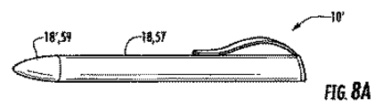
ECGデバイス10'は、その機能に一貫性がある任意の方法で構成されうる。すなわち、ECGデバイス10'は、ユーザのECGを得るための、手、胸部、または身体の他の部分上でユーザの皮膚に接触するために利用可能な電極、および、超音波を使用して受信デバイスにECGを送信するための手段を含むべきである。たとえば、手持ち式ECGデバイス10'は、下部表面上に2つの電極を有する図5の場合と同様のクレジットカードのように形作られうる、または、ECGデバイス10'は、保持者の手に接触する円筒表面57上に1つの電極18を有する図8Aの場合と同様のフラッシュライトまたはペンのように形作ることができ、他の電極18'は、使用時に、胸部、手、または他の身体部分に接触する端部59上にある。
The ECG device 10 'can be configured in any way that is consistent in its functionality. That is, the
別の構成では、ECGデバイス10'は、図8Bに示すようにスマートフォン保護ケース60として使用可能である。1つの例示的な構成は、iPhone(登録商標)または他のスマートフォン30用の「スリップオン(slip-on)」保護ケース60を利用し、保護ケース60は、統合されたECG電極アセンブリ18(ECGデータの単一誘導を生成するための2つ、3つ、または4つの電極)および取得エレクトロニクス11を含む。ECG電極は、ディスプレイスクリーン58の反対のケース60の側面62上に位置する。スマートフォン30は、そのECG適合保護ケース60内で両手で保持されうる(誘導I、左腕マイナス右腕を生成する)、または、人の胸部上に設置されて、修正胸部誘導を生成しうる。ECGは、取得エレクトロニクス11によって測定され、周波数変調超音波信号に変換される。適したキャリア周波数または中心周波数の非制限的な例は、約18kHz〜約24kHz、またはいくつかの実施形態では、約20kHz〜約24kHzを含む。周波数変調超音波信号は、小型スピーカ64または圧電ブザー66によって出力される。
In another configuration, the
別の構成では、図8Cに概略的に示すECGデバイス10'は、パッドとして使用可能である。パッド10'を使用するために、ユーザは、2つの電極18のそれぞれに手を置く。パッド10'ECGデバイスは、「ケース(case)」エレクトロニクスと同一であるが、スマートフォン30用の保護ケース60内に統合されるのではなく、自分自身のハウジング67内に存在する。1つの動作する例では、パッド10'は、手が置かれる電極として働く2つの別個の伝導性材料エリアを有するほぼA4ページサイズである。伝導性織物は、超音波を使用して受信デバイスにECGを送信する取得エレクトロニクス11「ポッド(pod)」に取付けるまたはクリップするための締結具61をパチンと嵌めるためにクリンプされた伝導性テールを有しうる。この実施形態は、ECGデータを取得し、PCまたは他のコンピューティングデバイスにECGデータを音響的に伝達して、ウェブアプリケーションおよび接続を介して復調し、処理し、記憶し、表示するデバイスの使用を可能にする。一方の側面にポッドを置くことは、パッドが、使用中に平らになり、保管のために折り畳まれて閉じることを可能にする。
In another configuration, the
ほとんどのコンピューティングデバイスおよび全てのスマートフォンは、メモリ56、ディスプレイスクリーン58、および、携帯アンテナ54を介して基地局またはウェブサーバ52に/から情報信号を送信/受信するための送受信機を含む。そのため、コンピューティングデバイスエレクトロニクスは、パーソナルモニタリングデバイス10からの情報をメモリ56に記憶し、かつ/または、当業者によって十分に理解されている無線通信技術を介してその情報を基地局52または特定の通信アドレスに送信するために使用されうる。
Most computing devices and all smartphones include a transceiver for transmitting / receiving information signals to / from a base station or
図9に概略的に示すさらに別の実施形態では、ECGデバイス10'は、フィットネス心拍数モニタのような胸部ストラップデバイス68として使用可能である。統合されたECG電極アセンブリ18および取得エレクトロニクス11「ポッド」を有する胸部ストラップ69は、周波数変調超音波ECG信号を生成し、その信号をスマートフォン30などのコンピューティングデバイス16に送出する。
In yet another embodiment schematically illustrated in FIG. 9, the
構成のうちの任意の構成では、スマートフォン30などのコンピューティングデバイス16は、その内蔵式マイクロフォン25およびCPUを利用して、ECGデータを、リアルタイムに、取得し、デジタル化し、復調し、処理し、次に表示する。同様に、コンピューティングデバイス16またはスマートフォン30は、リアルタイム心拍数測定値を計算し、心房細動などの心臓律動診断を下しうる。コンピューティングデバイス16またはスマートフォン30は、その2G、3G、4G、Bluetooth(登録商標)、およびWiFi接続性を利用して、ECGおよび他のデータをセキュアウェブサーバ52に送信して、リアルタイムに遠隔で表示し、記憶し、解析しうる。同様に、ECGデータは、後で検討するまたは送信するために、スマートフォン30上でローカルに記憶されうる。
In any of the configurations, a computing device 16 such as a
スマートフォン30上のソフトウェアはまた、GPSおよび加速度計などのスマートフォン30に内蔵された他のセンサからのデータおよび信号を組合せうる。このデータのさらなる処理は、速度、場所、距離、ステップ、歩調、体位、降下速度、およびエネルギー消費などのユーザに関連するさらなる情報を提供する。センサからの未処理信号および派生情報は、スマートフォン30上でローカルに表示され記憶されると共に、インターネット接続を通じてウェブサーバ52に送信されうる。ウェブサーバ52上のソフトウェアは、スマートフォン30から受信される信号および情報のリアルタイム表示または回顧的表示のためのウェブブラウザインタフェースを提供し、同様に、さらなる解析およびレポーティングを含む。
The software on the
ここで図10を参照すると、コンピュータ可読記憶媒体56は、命令72のセットを記憶し、命令72は、1つまたは複数のコンピューティングデバイス16によって実行されることが可能である。適したコンピューティングデバイス16の非制限的な例は、スマートフォン30、携帯情報端末(PDA)、タブレットパーソナルコンピュータ、ポケットパーソナルコンピュータ、ノートブックコンピュータ、デスクトップコンピュータ、およびサーバコンピュータを含む。命令72が実行されると、1つまたは複数のコンピューティングデバイス16は、超音波周波数変調ECG信号などのセンサ入力74をデジタル化し復調して、リアルタイム復調デジタルECGデータを生成するようにさせられる。命令72はまた、リアルタイム復調デジタルECGデータをコンピューティングデバイス16のディスプレイスクリーン58上に表示させうる。
Referring now to FIG. 10, the computer
FM復調のために使用される一般的な技法は、ゼロ交差検出に基づき、ゼロ交差間の時間間隔が、周波数を計算し、復調信号を再構成するために使用される。いくつかのアプリケーションでは、ゼロ交差間のオーディオサンプルの数を単に計数することが、周波数推定について十分な精度を提供することができる。精度は、サンプル間を補間することによって改善され、ゼロ交差点のよりよい推定値およびその後の周波数推定を提供する。ゼロ交差検出に基づくFM復調は、実装するのが簡単であり、FFTを使用する技法(高速フーリエ変換)などの他の技法と比較して計算をほとんど必要とせず、低電力可搬型コンピューティングデバイス上でのリアルタイムアプリケーションで使用するのに特に適する。 The general technique used for FM demodulation is based on zero crossing detection, and the time interval between zero crossings is used to calculate the frequency and reconstruct the demodulated signal. In some applications, simply counting the number of audio samples between zero crossings can provide sufficient accuracy for frequency estimation. The accuracy is improved by interpolating between samples, providing a better estimate of the zero crossing and subsequent frequency estimation. FM demodulation based on zero-crossing detection is easy to implement, requires little computation compared to other techniques such as FFT (Fast Fourier Transform), and is a low-power portable computing device Particularly suitable for use in real-time applications above.
しかし、FM狭帯域信号が、デジタル的にサンプリングされたオーディオのナイキスト周波数に近い場合、1サイクル当たりのサンプルが非常に少ないため、ゼロ交差推定の誤差が大きくなる。これは、超音波キャリア周波数についての典型的なゼロ交差復調技法の使用を厳しく制限する。本開示の実施形態は、正確な周波数推定によって、ゼロ交差技法の簡便性および効率を維持しながら、ナイキスト周波数に近いFM狭帯域信号を復調する方法を提供する。 However, if the FM narrowband signal is close to the Nyquist frequency of digitally sampled audio, there will be very few samples per cycle, leading to a large error in zero crossing estimation. This severely limits the use of typical zero crossing demodulation techniques for ultrasonic carrier frequencies. Embodiments of the present disclosure provide a method for demodulating an FM narrowband signal close to the Nyquist frequency while maintaining the simplicity and efficiency of the zero crossing technique with accurate frequency estimation.
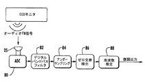
ここで図11を参照すると、ECG信号を示す超音波FM信号は、たとえば移動電話30または他のコンピューティングデバイス16内のマイクロフォン25によって受信され、アナログ信号に変換される。アナログ信号は、時間的に連続しており、アナログ-デジタル変換器80内でデジタル値のフローに変換され、FM復調器82内で復調され、スマートフォン30または他のコンピューティングデバイス16のディスプレイ58上で示される、または、記憶メモリ56内で保持される。一般にADCと呼ばれる実用的なアナログ-デジタル変換器80は瞬時変換を行うことができないため、入力値は、変換器が変換を実施する時間中、必ず一定に維持されなければならない。新しいデジタル値がアナログ信号からサンプリングされるレートは、ADCのサンプリングレートまたはサンプリング周波数と呼ばれる。移動電話および他のパーソナルコンピューティングデバイスは、通常、44kHzでオーディオを記録することに限定される。ANDROID(登録商標)およびiPHONE(登録商標)などの一部のスマートフォンは、48kHzでサンプリングできる。
Referring now to FIG. 11, an ultrasonic FM signal representing an ECG signal is received, for example, by the
デジタル化された超音波信号は、その後、FM信号の超音波キャリア周波数の近傍でバンドパスフィルタリングされて、信号対雑音比を改善し、通過帯域以外の好ましくないオーディオを低減しうる。図12に示すフィルタリング済みFM信号は、その後、オリジナルのオーディオのサンプリングレートの半分で「アンダーサンプリングされる(under-sampled)」。これは、FM信号のエイリアシングをもたらし、周波数スペクトルを低周波数帯域にシフトさせ反転させる。周波数スペクトルがアンダーサンプリング操作によって反転されるという結果は、復調出力が図13に示すように反転されることをもたらす。その反転は、最終の復調出力を単に変換することによって補正される。 The digitized ultrasound signal can then be bandpass filtered near the ultrasound carrier frequency of the FM signal to improve the signal-to-noise ratio and reduce unwanted audio outside the passband. The filtered FM signal shown in FIG. 12 is then “under-sampled” at half the original audio sampling rate. This results in aliasing of the FM signal and shifts and inverts the frequency spectrum to the lower frequency band. The result that the frequency spectrum is inverted by the undersampling operation results in the demodulated output being inverted as shown in FIG. The inversion is corrected by simply converting the final demodulated output.
低周波数のFM信号によって、1サイクル当たりのオーディオサンプルが多くなり、ゼロ交差推定などの復調プロセスが大幅に正確になる。たとえば、ゼロ交差検出器は、オーディオ信号が符号を変更する場合にゼロ交差を識別する。ゼロ交差点の精度は、ゼロ交差の両側でサンプル間を線形補間することによってさらに改善される。最後に、ゼロ交差間の期間は、周波数の推定値を計算し、復調信号を再構成するために使用される。上述した復調プロシージャはゼロ交差推定を利用するが、他の復調プロシージャが利用されうること、および、他の復調プロシージャの精度もまた、アンダーサンプリング操作から利益を受けることになることが理解される。 The low frequency FM signal increases the number of audio samples per cycle, making demodulation processes such as zero crossing estimation much more accurate. For example, a zero crossing detector identifies a zero crossing when the audio signal changes sign. Zero crossing accuracy is further improved by linearly interpolating between samples on either side of the zero crossing. Finally, the period between zero crossings is used to calculate an estimate of the frequency and reconstruct the demodulated signal. Although the demodulation procedure described above utilizes zero-crossing estimation, it is understood that other demodulation procedures can be used and that the accuracy of other demodulation procedures will also benefit from undersampling operations.
(実施例)
図14に示す1つの動作する例では、システムは、可搬型ECGモニタから移動電話30ならびにパーソナルコンピュータ16内のマイクロフォン25に送信される超音波FM ECG信号を使用した。これは、信号を受信するさらなるハードウェアを全く必要とすることなく、マイクロフォンを有するほとんどの移動電話およびコンピュータに適合する低コストの無線送信解決策を提供した。
(Example)
In one working example shown in FIG. 14, the system used an ultrasonic FM ECG signal transmitted from a portable ECG monitor to the
FM信号は、18kHzを超えるため、ほとんどの人々に聞きこえず、音楽またはスピーチを邪魔せず、オーディオ干渉を受けにくいことが望ましい。FM信号が、オーディオ干渉に対するその感受性をさらに低減するために狭い帯域幅を有することが同様に望ましい。この場合、ECGモニタは、200Hz/mVのECGによって変調され、±5mVの範囲を有する19kHzの超音波FMキャリアを使用した。これは、18kHzと20kHzとの間の超音波FM信号をもたらした。 Since FM signals exceed 18kHz, it is desirable that most people do not hear them, do not disturb music or speech, and are not susceptible to audio interference. It is also desirable for the FM signal to have a narrow bandwidth to further reduce its susceptibility to audio interference. In this case, the ECG monitor used a 19 kHz ultrasonic FM carrier modulated by a 200 Hz / mV ECG and having a range of ± 5 mV. This resulted in an ultrasonic FM signal between 18kHz and 20kHz.
最初に、オーディオFM信号は、マイクロフォン25によって受信され、移動電話30内のADC80によって44kHzでデジタル化された。オーディオは、その後、フィルタ82内で18kHzと20kHzとの間でバンドパスフィルタリングされて、通過帯域以外のオーディオ雑音が除去された。次のステージ84にて、オーディオは、1秒ごとのオーディオサンプルだけが使用される22kHzでアンダーサンプリングされた。こうしたアンダーサンプリング後に生成されるデジタル信号は、周波数スペクトルをシフトさせ、反転させるエイリアシングをもたらすため、周波数スペクトルが2kHz〜4kHz範囲にあるように見える。ゼロ交差検出器86は、その後、オーディオ信号が符号を変更する場所を識別する。ゼロ交差点は、その後、ゼロ交差の両側でサンプル間を線形補間することによって、周波数推定ステップ88においてより正確に計算される。この例では、周波数推定値は、3.33msごとに必要とされるだけであり、それについて、300Hzで出力信号が復調される。これは、ゼロ交差の数を計数し、最も近い固定数のサイクルにわたる期間を測定し、この期間中に、固定した300Hz出力を提供することによって達成される。復調出力は、その後、反転されて、周波数スペクトルがアンダーサンプリング操作によって反転されるのを補正される。最後に、300Hz復調ECGデータは、関心のECG帯域幅が40Hz未満であるため、40Hzローパスフィルタを通される。これは、周波数推定値および復調出力からの雑音をさらに低減する。FM復調器は、16ビット、300Hz ECGを出力する。
Initially, the audio FM signal was received by
センサ入力74はまた、さらなるセンサならびにユーザ入力74'からのリアルタイム情報を含みうる。たとえば、コンピューティングデバイス16がスマートフォン30である実施形態では、入力74は、復調デジタルECGデータに加えて、スマートフォン30内のGPSおよび/または加速度計からのリアルタイム情報を含みうる。ユーザ入力74'はまた、コンピューティングデバイス16のマイクロフォンを通して入力される話された音声メッセージを含みうる。命令72は、センサ入力74および/またはユーザ入力74'が、コンピューティングデバイス16の記憶メモリ56内に記録され維持されるようにさせうる。
一実施形態では、命令72のセットは、1つまたは複数のコンピューティングデバイス16によって実行されると、1つまたは複数のコンピューティングデバイス16が、周波数変調ECG超音波信号によって示される心拍数をリアルタイムに計算し表示するようにさらにさせうる。さらに、復調デジタルECGデータは、不整脈の発生を識別するために処理されうる。こうした設計では、記憶媒体70は、コンピューティングデバイス16が、不整脈の発生時に、ディスプレイスクリーン58上に警告を表示する、または、スピーカ76を通して可聴報知を発するようにさせる命令72を含みうる。
In one embodiment, when the set of
命令72は、コンピューティングデバイス16が、後で取出すために、1つまたは複数のコンピューティングデバイス16のメモリ56に復調デジタルECGデータを記憶するようにさせうる。命令72のセットは、1つまたは複数のコンピューティングデバイス16が、要求に応じて、記憶された復調デジタルECGデータを取出し、コンピューティングデバイス16上のインターネット接続を介してウェブサーバ52に送信するようにさらにさせうる。記録済みの話された音声メッセージは、復調デジタルECGデータと同時に記憶され、ウェブサーバ52に送信されうる。
他の実施形態では、命令72は、1つまたは複数のコンピューティングデバイス16が、復調デジタルECGデータおよび/または音声メッセージをウェブサーバ52にリアルタイムに送信するようにさせうる。
In other embodiments, the
スマートフォンソフトウェアのバージョンは、他のサードパーティソフトウェアアプリケーションと統合されうるソフトウェアライブラリとしてパッケージされる。これは、サードパーティアプリケーションが、それ自身のデータ取得、復調、および信号処理アルゴリズムを開発する必要なしで、心拍数および他の派生情報を得るためにECGデバイス10'を使用するための簡略化されかつ標準的な方法を提供する。 Smartphone software versions are packaged as software libraries that can be integrated with other third-party software applications. This is simplified for third party applications to use ECG device 10 'to obtain heart rate and other derived information without having to develop their own data acquisition, demodulation and signal processing algorithms. And provide a standard method.
ソフトウェアのバージョンはまた、PC上で実行され、復調、処理、記憶、およびウェブサーバ52に対する送信を含む。ソフトウェアは、オーディオ取得モジュール、復調モジュール、ECG解析モジュール、および加速度解析モジュールを含む。
The software version also runs on the PC and includes demodulation, processing, storage, and transmission to the
ADCからのオーディオサンプルは、任意選択で、デジタルバンドパスフィルタを通されて、変調範囲以外の好ましくない周波数を除去する。復調モジュールは、オーディオサンプルの周波数の約半分でのアンダーサンプリングを使用して周波数変調ECG超音波信号を復調して、スペクトルを低周波数範囲にシフトさせ、それに続いて、線形近似およびゼロ交差アルゴリズムが行われる。復調器は、異なる変調パラメータの選択が、特定のECGデバイスに適合することを可能にする。ゼロ交差および線形近似だけを使用する復調は、44kHzサンプリングによる6kHz以下、10kHzを超えるキャリア周波数の場合うまく働くが、線形近似による誤差は、スペクトルをシフトさせるためにアンダーサンプリングが使用されない場合大きくなる。 Audio samples from the ADC are optionally passed through a digital bandpass filter to remove unwanted frequencies outside the modulation range. The demodulation module demodulates the frequency modulated ECG ultrasound signal using undersampling at approximately half the frequency of the audio sample to shift the spectrum to a lower frequency range, followed by linear approximation and zero crossing algorithms. Done. The demodulator allows the selection of different modulation parameters to be adapted to a specific ECG device. Demodulation using only zero crossings and linear approximation works well for carrier frequencies below 6 kHz with 44 kHz sampling and above 10 kHz, but the error due to linear approximation is large when undersampling is not used to shift the spectrum.
アルゴリズムは、その後、到来するデータの符号を見る。符号が変化すると、アルゴリズムは、2点間に直線を引き、ゼロ値を補間する。アルゴリズムは、これを使用して、3.333ms間隔を超える平均周波数を決定し、300Hzの出力サンプリングレートでECGデータを提供する。 The algorithm then looks at the sign of the incoming data. When the sign changes, the algorithm draws a straight line between the two points and interpolates the zero value. The algorithm uses this to determine the average frequency over the 3.333 ms interval and provide ECG data at an output sampling rate of 300 Hz.
ECG解析モジュールは、ECGを処理して、拍動を検出し分類するアルゴリズムを含み、心拍数推定値を提供する。拍動-拍動心拍数は、拍動間の間隔から計算され、心拍数のより頑健な測定値が、RR間隔の中間値フィルタリングを使用して計算される。 The ECG analysis module includes an algorithm that processes the ECG to detect and classify beats and provides a heart rate estimate. Beat-to-beat heart rate is calculated from the interval between beats, and a more robust measure of heart rate is calculated using median filtering of the RR interval.
加速度解析モジュールは、スマートフォン30内の内蔵式3軸加速度計センサからの信号を処理して、人のエネルギー消費の推定値、ステップ、歩調、および体位を導出し、降下を検出するアルゴリズムを含む。
The acceleration analysis module includes an algorithm that processes signals from a built-in triaxial accelerometer sensor in the
上記説明から、目下開示され請求される本発明の概念が、目下開示され請求される本発明の概念に固有の目的および利点と同様に、本明細御書で述べる目的を果たし、本明細御書で述べる利点を得るようにうまく適合されることが明らかである。提示される実施形態は、本開示のために述べられたが、当業者の頭に容易に浮かぶことになり、また、目下開示され請求される本発明の概念の精神内で達成される多数の変更を行うことができることが理解されるであろう。 From the foregoing description, the presently disclosed and claimed subject matter serves the purposes described herein, as well as the objectives and advantages inherent in the presently disclosed and claimed subject matter. It is clear that it is well adapted to obtain the advantages described in. While the presented embodiments have been set forth for the purpose of this disclosure, they will readily come to mind of those skilled in the art and are numerous within the spirit of the inventive concept presently disclosed and claimed. It will be understood that changes can be made.
10 モニタリングデバイス
10' ECGデバイス
11 取得エレクトロニクス
12 センサアセンブリ
12' マイクロフォン補助聴診器
14 変換器アセンブリ
16 コンピューティングデバイス(コンピュータ)
18 電極アセンブリ(電極)
18' 電極
20 誘導線
24 超音波送信機
25 内蔵マイクロフォン
30 スマートフォン、移動電話
52 ウェブサーバ
54 携帯アンテナ
56 メモリ
57 円筒表面
58 ディスプレイスクリーン
59 端部
60 スマートフォン保護ケース
61 締結具
62 側面
64 小型スピーカ
66 圧電ブザー
67 ハウジング
68 胸部ストラップデバイス
70 コントローラ
72 命令
74 センサ入力
74' ユーザ入力
80 アナログ-デジタル変換器(ADC)
82 デジタルバンドパスフィルタ
84 アンダーサンプリング
86 ゼロ交差検出
88 周波数推定
10 Monitoring device
10 'ECG device
11 Acquired electronics
12 Sensor assembly
12 'microphone-assisted stethoscope
14 Transmitter assembly
16 Computing device (computer)
18 Electrode assembly (electrode)
18 'electrode
20 Guide wire
24 ultrasonic transmitter
25 Built-in microphone
30 Smartphones, mobile phones
52 Web server
54 Mobile antenna
56 memory
57 Cylindrical surface
58 display screen
59 Edge
60 Smartphone protective case
61 Fastener
62 Side
64 Small speaker
66 Piezoelectric buzzer
67 Housing
68 Chest strap device
70 controller
72 instructions
74 Sensor input
74 'User input
80 Analog-to-digital converter (ADC)
82 Digital bandpass filter
84 Undersampling
86 Zero crossing detection
88 Frequency estimation
Claims (34)
ユーザの皮膚に接触すると生理的信号を検知し、前記検知された生理的信号を示す電気信号を生成するように構成されるセンサアセンブリと、
オーディオ送信機を含む変換器アセンブリとを備え、前記変換器アセンブリは、前記センサアセンブリと統合されかつ前記センサアセンブリに電気接続され、また、前記センサによって生成される前記電気信号を受信し、前記信号を前記オーディオ送信機の範囲内で前記オーディオ送信機を通してコンピューティングデバイス内のマイクロフォンへ出力するように構成され、前記変換器アセンブリは、前記信号を、非可聴超音波周波数変調(FM)音信号として出力するようにさらに構成されるパーソナルモニタリングデバイス。 A personal monitoring device,
A sensor assembly configured to sense a physiological signal upon contact with a user's skin and generate an electrical signal indicative of the sensed physiological signal;
A transducer assembly including an audio transmitter, wherein the transducer assembly is integrated with and electrically connected to the sensor assembly and receives the electrical signal generated by the sensor; In the range of the audio transmitter and through the audio transmitter to a microphone in a computing device, the transducer assembly configured to output the signal as an inaudible ultrasonic frequency modulation (FM) sound signal. A personal monitoring device further configured to output.
ユーザの皮膚に接触すると心臓関連信号を検知し、前記検知された心臓関連信号をECG電気信号に変換するように構成される電極アセンブリと、
オーディオ送信機を含む変換器アセンブリとを備え、前記変換器アセンブリは、前記センサアセンブリと統合されかつ前記センサアセンブリに電気接続され、また、前記アセンブリによって生成される前記ECG電気信号を受信し、ECG音信号を前記オーディオ送信機の範囲内で前記オーディオ送信機を通してコンピューティングデバイス内のマイクロフォンに出力するように構成され、前記変換器アセンブリは、前記ECG信号を、超音波FM音信号として出力するようにさらに構成されるECGデバイス。 An ECG device,
An electrode assembly configured to detect a heart related signal upon contact with a user's skin and convert the detected heart related signal to an ECG electrical signal;
A transducer assembly including an audio transmitter, the transducer assembly being integrated with and electrically connected to the sensor assembly, and receiving the ECG electrical signal generated by the assembly; Configured to output a sound signal within the range of the audio transmitter through the audio transmitter to a microphone in a computing device, wherein the transducer assembly outputs the ECG signal as an ultrasonic FM sound signal. ECG device further configured to.
ユーザの皮膚に接触すると心臓関連信号を検知し、前記検知された心臓関連信号をECG電気信号に変換するように構成される電極アセンブリと、
前記電極アセンブリと統合されかつ前記電極アセンブリに電気接続された変換器アセンブリとを備え、前記変換器アセンブリは、前記電極アセンブリによって生成される前記ECG電気信号を約18kHz〜約24kHzの範囲のキャリア周波数を有する超音波FM音信号に変換するように構成され、オーディオ送信機を通して、前記スマートフォン保護ケース内に配置されたスマートフォンによって受信されることが可能な信号強度で前記超音波FM音信号を出力するようにさらに構成されるスマートフォン保護ケース。 A smartphone protective case that can be used as an ECG device,
An electrode assembly configured to detect a heart related signal upon contact with a user's skin and convert the detected heart related signal to an ECG electrical signal;
A transducer assembly integrated with and electrically connected to the electrode assembly, wherein the transducer assembly transmits the ECG electrical signal generated by the electrode assembly in a range of about 18 kHz to about 24 kHz. The ultrasonic FM sound signal is output at a signal intensity that can be received by a smartphone disposed in the smartphone protective case through an audio transmitter, and configured to convert the ultrasonic FM sound signal to Smartphone protective case further configured as.
ユーザの皮膚に接触すると心臓関連信号を検知し、前記検知された心臓関連信号をECG電気信号に変換するように構成される電極アセンブリと、
オーディオ送信機を含む変換器アセンブリであって、前記電極アセンブリと統合されかつ前記電極アセンブリに電気接続され、また、前記ECG電気信号を超音波FM音信号に変換し、前記超音波FM音信号を前記オーディオ送信機を通してコンピューティングデバイス内のマイクロフォンに出力するように構成され、前記コンピューティングデバイスのアナログ-デジタル変換器(ADC)は、前記マイクロフォンからの信号をサンプリングし、前記信号をデジタルオーディオ信号に変換するように構成される、変換器アセンブリと、
非一時的コンピュータ可読媒体上に記憶され、前記コンピューティングデバイスによって実行可能な復調ソフトウェアであって、それにより、前記前記コンピューティングデバイスが、(1)前記デジタルオーディオ信号をアンダーサンプリングし、前記デジタルオーディオ信号を低周波帯域になるようエイリアシングし、(2)前記エイリアシングされたデジタルオーディオ信号を前記低周波帯域で復調して、ECG出力を生成するようにさせる、復調ソフトウェアとを備えるシステム。 A system for generating and transferring medical data,
An electrode assembly configured to detect a heart related signal upon contact with a user's skin and convert the detected heart related signal to an ECG electrical signal;
A transducer assembly including an audio transmitter, integrated with and electrically connected to the electrode assembly, and converting the ECG electrical signal to an ultrasonic FM sound signal, Configured to output to a microphone in a computing device through the audio transmitter, the analog-to-digital converter (ADC) of the computing device samples the signal from the microphone and converts the signal into a digital audio signal A transducer assembly configured to convert; and
Demodulation software stored on a non-transitory computer readable medium and executable by the computing device, whereby the computing device (1) undersamples the digital audio signal and the digital audio And (2) demodulating software for demodulating the aliased digital audio signal in the low frequency band to generate an ECG output.
ユーザの皮膚に接触状態でECGデバイスの電極アセンブリを設置するステップであって、前記電極アセンブリは、心臓関連信号を検知し、前記検知された心臓関連信号をECG電気信号に変換するように構成される、設置するステップと、
前記ECG信号を超音波FM音信号として送信するために前記ECGデバイスの変換器アセンブリを利用するステップであって、前記変換器アセンブリは、オーディオ送信機を含み、前記変換器アセンブリは、前記センサアセンブリと統合されかつ前記センサアセンブリに電気接続され、また、前記アセンブリによって生成される前記ECG電気信号を受信し、前記オーディオ送信機を通してECG音信号を超音波FM音信号として出力するように構成される、利用するステップと、
前記オーディオ送信機の範囲内で、コンピューティングデバイス内のマイクロフォンで前記超音波FM音信号を受信し、前記超音波FM信号を復調し、結果として得られるECG出力を記録するステップと、
任意選択で、前記ECG出力と同時に、話された音声メッセージを記録するステップとを含む方法。 A health monitoring method,
Installing an electrode assembly of an ECG device in contact with a user's skin, wherein the electrode assembly is configured to detect a heart related signal and convert the detected heart related signal into an ECG electrical signal; Step to install,
Utilizing a transducer assembly of the ECG device to transmit the ECG signal as an ultrasonic FM sound signal, the transducer assembly including an audio transmitter, the transducer assembly comprising the sensor assembly. Integrated with and electrically connected to the sensor assembly, and configured to receive the ECG electrical signal generated by the assembly and output the ECG sound signal as an ultrasonic FM sound signal through the audio transmitter , The steps to use,
Within the range of the audio transmitter, receiving the ultrasonic FM sound signal with a microphone in a computing device, demodulating the ultrasonic FM signal, and recording the resulting ECG output;
Optionally recording the spoken voice message simultaneously with the ECG output.
Applications Claiming Priority (3)
| Application Number | Priority Date | Filing Date | Title |
|---|---|---|---|
| US13/108,738 US20110301439A1 (en) | 2010-06-08 | 2011-05-16 | Wireless, ultrasonic personal health monitoring system |
| US13/108,738 | 2011-05-16 | ||
| PCT/US2011/053708 WO2012158190A1 (en) | 2011-05-16 | 2011-09-28 | Wireless, ultrasonic personal health monitoring system |
Publications (2)
| Publication Number | Publication Date |
|---|---|
| JP2014518713A true JP2014518713A (en) | 2014-08-07 |
| JP2014518713A5 JP2014518713A5 (en) | 2014-11-13 |
Family
ID=47177241
Family Applications (1)
| Application Number | Title | Priority Date | Filing Date |
|---|---|---|---|
| JP2014511335A Pending JP2014518713A (en) | 2011-05-16 | 2011-09-28 | Wireless ultrasonic personal health monitoring system |
Country Status (6)
| Country | Link |
|---|---|
| US (1) | US20110301439A1 (en) |
| EP (1) | EP2710546A4 (en) |
| JP (1) | JP2014518713A (en) |
| CN (2) | CN102835953A (en) |
| TW (1) | TW201247170A (en) |
| WO (1) | WO2012158190A1 (en) |
Cited By (1)
| Publication number | Priority date | Publication date | Assignee | Title |
|---|---|---|---|---|
| JP2021518184A (en) * | 2018-03-16 | 2021-08-02 | アライヴコア・インコーポレーテッド | Mobile ECG sensor device |
Families Citing this family (137)
| Publication number | Priority date | Publication date | Assignee | Title |
|---|---|---|---|---|
| EP3827747A1 (en) | 2005-04-28 | 2021-06-02 | Otsuka Pharmaceutical Co., Ltd. | Pharma-informatics system |
| US8730031B2 (en) | 2005-04-28 | 2014-05-20 | Proteus Digital Health, Inc. | Communication system using an implantable device |
| US9198608B2 (en) | 2005-04-28 | 2015-12-01 | Proteus Digital Health, Inc. | Communication system incorporated in a container |
| US8547248B2 (en) | 2005-09-01 | 2013-10-01 | Proteus Digital Health, Inc. | Implantable zero-wire communications system |
| JP2009544338A (en) | 2006-05-02 | 2009-12-17 | プロテウス バイオメディカル インコーポレイテッド | Treatment regimen customized to the patient |
| KR101611240B1 (en) | 2006-10-25 | 2016-04-11 | 프로테우스 디지털 헬스, 인코포레이티드 | Controlled activation ingestible identifier |
| WO2008063626A2 (en) | 2006-11-20 | 2008-05-29 | Proteus Biomedical, Inc. | Active signal processing personal health signal receivers |
| MY165532A (en) | 2007-02-01 | 2018-04-02 | Proteus Digital Health Inc | Ingestible event marker systems |
| EP2111661B1 (en) | 2007-02-14 | 2017-04-12 | Proteus Digital Health, Inc. | In-body power source having high surface area electrode |
| WO2008112577A1 (en) | 2007-03-09 | 2008-09-18 | Proteus Biomedical, Inc. | In-body device having a multi-directional transmitter |
| US8540632B2 (en) | 2007-05-24 | 2013-09-24 | Proteus Digital Health, Inc. | Low profile antenna for in body device |
| EP4011289A1 (en) | 2007-09-25 | 2022-06-15 | Otsuka Pharmaceutical Co., Ltd. | In-body device with virtual dipole signal amplification |
| US20090135886A1 (en) | 2007-11-27 | 2009-05-28 | Proteus Biomedical, Inc. | Transbody communication systems employing communication channels |
| JP2011513865A (en) | 2008-03-05 | 2011-04-28 | プロテウス バイオメディカル インコーポレイテッド | Multi-mode communication ingestible event marker and system and method of using the same |
| WO2010005877A2 (en) | 2008-07-08 | 2010-01-14 | Proteus Biomedical, Inc. | Ingestible event marker data framework |
| SG172077A1 (en) | 2008-12-11 | 2011-07-28 | Proteus Biomedical Inc | Evaluation of gastrointestinal function using portable electroviscerography systems and methods of using the same |
| US9439566B2 (en) | 2008-12-15 | 2016-09-13 | Proteus Digital Health, Inc. | Re-wearable wireless device |
| TWI503101B (en) | 2008-12-15 | 2015-10-11 | Proteus Digital Health Inc | Body-associated receiver and method |
| US9659423B2 (en) | 2008-12-15 | 2017-05-23 | Proteus Digital Health, Inc. | Personal authentication apparatus system and method |
| WO2013012869A1 (en) | 2011-07-21 | 2013-01-24 | Proteus Digital Health, Inc. | Mobile communication device, system, and method |
| CN102341031A (en) | 2009-01-06 | 2012-02-01 | 普罗秋斯生物医学公司 | Ingestion-related biofeedback and personalized medical therapy method and system |
| US9144388B2 (en) | 2009-01-20 | 2015-09-29 | Alfred Salazar | Portable system and method for monitoring of a heart and other body functions |
| TWI517050B (en) | 2009-11-04 | 2016-01-11 | 普羅托斯數位健康公司 | System for supply chain management |
| AU2011210648B2 (en) | 2010-02-01 | 2014-10-16 | Otsuka Pharmaceutical Co., Ltd. | Data gathering system |
| TWI557672B (en) | 2010-05-19 | 2016-11-11 | 波提亞斯數位康健公司 | Computer system and computer-implemented method to track medication from manufacturer to a patient, apparatus and method for confirming delivery of medication to a patient, patient interface device |
| US8700137B2 (en) | 2012-08-30 | 2014-04-15 | Alivecor, Inc. | Cardiac performance monitoring system for use with mobile communications devices |
| US8509882B2 (en) | 2010-06-08 | 2013-08-13 | Alivecor, Inc. | Heart monitoring system usable with a smartphone or computer |
| US9351654B2 (en) | 2010-06-08 | 2016-05-31 | Alivecor, Inc. | Two electrode apparatus and methods for twelve lead ECG |
| US8301232B2 (en) * | 2010-06-08 | 2012-10-30 | Alivecor, Inc. | Wireless, ultrasonic personal health monitoring system |
| US20110301439A1 (en) * | 2010-06-08 | 2011-12-08 | AliveUSA LLC | Wireless, ultrasonic personal health monitoring system |
| US9439599B2 (en) | 2011-03-11 | 2016-09-13 | Proteus Digital Health, Inc. | Wearable personal body associated device with various physical configurations |
| US8560031B2 (en) | 2011-03-16 | 2013-10-15 | David B. Barnett | Extending socket for portable media player |
| WO2012142432A1 (en) | 2011-04-15 | 2012-10-18 | Mrn Partners Llp | Remote health monitoring system |
| AU2012255644A1 (en) | 2011-05-17 | 2013-11-28 | Lionsgate Technologies, Inc. | Systems and methods for determining physiological characteristics of a patient using pulse oximetry |
| US20120330178A1 (en) * | 2011-06-24 | 2012-12-27 | U.S. Government As Represented By The Secretary Of The Army | Method and apparatus for multimodal mobile screening to quantitatively detect brain function impairment |
| US9756874B2 (en) | 2011-07-11 | 2017-09-12 | Proteus Digital Health, Inc. | Masticable ingestible product and communication system therefor |
| WO2015112603A1 (en) | 2014-01-21 | 2015-07-30 | Proteus Digital Health, Inc. | Masticable ingestible product and communication system therefor |
| US9235683B2 (en) | 2011-11-09 | 2016-01-12 | Proteus Digital Health, Inc. | Apparatus, system, and method for managing adherence to a regimen |
| TWM432391U (en) * | 2012-01-04 | 2012-07-01 | Vicon Healthcare Int Inc | An improved device for collecting a physiological signal |
| CN103251403A (en) * | 2012-02-17 | 2013-08-21 | 钱军 | Portable electrocardio measuring system and manufacture method thereof |
| CN103251397A (en) * | 2012-02-17 | 2013-08-21 | 钱军 | Portable blood pressure measuring system and manufacture method thereof |
| US11452153B2 (en) | 2012-05-01 | 2022-09-20 | Lisnr, Inc. | Pairing and gateway connection using sonic tones |
| KR20150020319A (en) | 2012-05-01 | 2015-02-25 | 엘아이에스엔알, 인크. | Systems and methods for content delivery and management |
| WO2014028899A1 (en) * | 2012-08-16 | 2014-02-20 | Alivecor, Inc. | Ultrasonic transmission of signals |
| US20140073969A1 (en) * | 2012-09-12 | 2014-03-13 | Neurosky, Inc. | Mobile cardiac health monitoring |
| KR101306659B1 (en) * | 2012-09-28 | 2013-09-10 | 이충헌 | Health management system possible biomedical signal detection using aux |
| US20150294539A1 (en) * | 2012-10-31 | 2015-10-15 | Promotie Voor Speciale Evenementen - Belgium | Method for remotely controlling human perceivable output of a plurality of devices, system, transmitter, device, software product and human unperceivable acoustic signal for performing the method |
| US20140128754A1 (en) * | 2012-11-08 | 2014-05-08 | Aliphcom | Multimodal physiological sensing for wearable devices or mobile devices |
| WO2014074913A1 (en) | 2012-11-08 | 2014-05-15 | Alivecor, Inc. | Electrocardiogram signal detection |
| US9445768B2 (en) * | 2012-11-29 | 2016-09-20 | Neurosky, Inc. | Personal biosensor accessory attachment |
| JP2014116652A (en) * | 2012-12-06 | 2014-06-26 | Scalar Corp | Sensor device, sensor system, and program |
| US9042568B2 (en) * | 2012-12-11 | 2015-05-26 | Barry Poplaw | Portable smart stethoscope formed of smart mobile device and casing assembly |
| WO2014107700A1 (en) | 2013-01-07 | 2014-07-10 | Alivecor, Inc. | Methods and systems for electrode placement |
| US9254092B2 (en) | 2013-03-15 | 2016-02-09 | Alivecor, Inc. | Systems and methods for processing and analyzing medical data |
| JP6498177B2 (en) | 2013-03-15 | 2019-04-10 | プロテウス デジタル ヘルス, インコーポレイテッド | Identity authentication system and method |
| ES2692666T3 (en) * | 2013-04-16 | 2018-12-04 | Alivecor, Inc. | Two-lead electrode device and methods for twelve-lead ECG |
| JP6511439B2 (en) | 2013-06-04 | 2019-05-15 | プロテウス デジタル ヘルス, インコーポレイテッド | Systems, devices, and methods for data collection and outcome assessment |
| US9247911B2 (en) | 2013-07-10 | 2016-02-02 | Alivecor, Inc. | Devices and methods for real-time denoising of electrocardiograms |
| WO2015035251A1 (en) * | 2013-09-06 | 2015-03-12 | Alivecor, Inc. | Universal ecg electrode module for smartphone |
| MX356850B (en) | 2013-09-20 | 2018-06-15 | Proteus Digital Health Inc | Methods, devices and systems for receiving and decoding a signal in the presence of noise using slices and warping. |
| US9577864B2 (en) | 2013-09-24 | 2017-02-21 | Proteus Digital Health, Inc. | Method and apparatus for use with received electromagnetic signal at a frequency not known exactly in advance |
| US9414155B2 (en) * | 2013-10-15 | 2016-08-09 | Stratoscientific, Inc. | Acoustic collection system for handheld electronic devices |
| US10084880B2 (en) | 2013-11-04 | 2018-09-25 | Proteus Digital Health, Inc. | Social media networking based on physiologic information |
| US9420956B2 (en) | 2013-12-12 | 2016-08-23 | Alivecor, Inc. | Methods and systems for arrhythmia tracking and scoring |
| WO2016039900A1 (en) | 2014-09-12 | 2016-03-17 | Exxonmobil Upstream Research Comapny | Discrete wellbore devices, hydrocarbon wells including a downhole communication network and the discrete wellbore devices and systems and methods including the same |
| JP6882168B2 (en) | 2014-10-15 | 2021-06-02 | エルアイエスエヌアール・インコーポレーテッド | Inaudible signaling tone |
| CN104398253A (en) * | 2014-11-07 | 2015-03-11 | 吴嘉浚 | Wireless single-lead mobile electrocardiograph |
| US10408047B2 (en) | 2015-01-26 | 2019-09-10 | Exxonmobil Upstream Research Company | Real-time well surveillance using a wireless network and an in-wellbore tool |
| US10292607B2 (en) | 2015-03-26 | 2019-05-21 | Intel Corporation | Sensor data transmissions |
| KR102420009B1 (en) * | 2015-04-08 | 2022-07-12 | 삼성전자주식회사 | apparatus for measuring biological information |
| US9839363B2 (en) | 2015-05-13 | 2017-12-12 | Alivecor, Inc. | Discordance monitoring |
| GB2538510B (en) * | 2015-05-18 | 2019-10-16 | Humberto Jose Moran Cirkovic | Interoperating sensing devices and mobile devices |
| US9800703B2 (en) | 2015-11-23 | 2017-10-24 | TecTide Group, LLC | Handling apparatus for portable electronic devices |
| CN106923799A (en) * | 2015-12-30 | 2017-07-07 | 周国明 | A kind of mobile phone with health supervision and feedback treating function |
| KR102333027B1 (en) * | 2016-01-25 | 2021-12-01 | 삼성전자주식회사 | Portable device having exhalation sensing function |
| US10517531B2 (en) | 2016-02-08 | 2019-12-31 | Vardas Solutions LLC | Stress management using biofeedback |
| US10398350B2 (en) | 2016-02-08 | 2019-09-03 | Vardas Solutions LLC | Methods and systems for providing a breathing rate calibrated to a resonance breathing frequency |
| WO2017138921A1 (en) * | 2016-02-09 | 2017-08-17 | Sony Mobile Communications Inc. | Electromyography-enhanced body area network system and method |
| US11233582B2 (en) | 2016-03-25 | 2022-01-25 | Lisnr, Inc. | Local tone generation |
| USD794806S1 (en) | 2016-04-29 | 2017-08-15 | Infobionic, Inc. | Health monitoring device |
| USD794805S1 (en) | 2016-04-29 | 2017-08-15 | Infobionic, Inc. | Health monitoring device with a button |
| US9968274B2 (en) | 2016-04-29 | 2018-05-15 | Infobionic, Inc. | Systems and methods for processing ECG data |
| USD794807S1 (en) | 2016-04-29 | 2017-08-15 | Infobionic, Inc. | Health monitoring device with a display |
| CN109843149B (en) | 2016-07-22 | 2020-07-07 | 普罗秋斯数字健康公司 | Electromagnetic sensing and detection of ingestible event markers |
| WO2018023694A1 (en) * | 2016-08-05 | 2018-02-08 | 深圳市汇顶科技股份有限公司 | Signal transmission method and apparatus |
| US10054259B2 (en) | 2016-08-17 | 2018-08-21 | Popsockets Llc | Expanding socket accessory for mobile electronic device |
| US11828172B2 (en) | 2016-08-30 | 2023-11-28 | ExxonMobil Technology and Engineering Company | Communication networks, relay nodes for communication networks, and methods of transmitting data among a plurality of relay nodes |
| US10526888B2 (en) | 2016-08-30 | 2020-01-07 | Exxonmobil Upstream Research Company | Downhole multiphase flow sensing methods |
| US10697287B2 (en) | 2016-08-30 | 2020-06-30 | Exxonmobil Upstream Research Company | Plunger lift monitoring via a downhole wireless network field |
| US10344583B2 (en) | 2016-08-30 | 2019-07-09 | Exxonmobil Upstream Research Company | Acoustic housing for tubulars |
| US10590759B2 (en) | 2016-08-30 | 2020-03-17 | Exxonmobil Upstream Research Company | Zonal isolation devices including sensing and wireless telemetry and methods of utilizing the same |
| US10465505B2 (en) | 2016-08-30 | 2019-11-05 | Exxonmobil Upstream Research Company | Reservoir formation characterization using a downhole wireless network |
| US10415376B2 (en) | 2016-08-30 | 2019-09-17 | Exxonmobil Upstream Research Company | Dual transducer communications node for downhole acoustic wireless networks and method employing same |
| US10364669B2 (en) | 2016-08-30 | 2019-07-30 | Exxonmobil Upstream Research Company | Methods of acoustically communicating and wells that utilize the methods |
| KR20180027901A (en) * | 2016-09-07 | 2018-03-15 | 삼성전자주식회사 | Remote controller and method for controlling thereof |
| KR20180028703A (en) * | 2016-09-09 | 2018-03-19 | 삼성전자주식회사 | Display apparatus and method for setting remote controller using the display apparatus |
| WO2018089789A1 (en) | 2016-11-10 | 2018-05-17 | The Research Foundation For The State University Of New York | System, method and biomarkers for airway obstruction |
| CN106725415B (en) * | 2016-11-15 | 2019-10-18 | 广州视源电子科技股份有限公司 | The treating method and apparatus of electricity physiological signal |
| WO2019010108A1 (en) * | 2017-07-06 | 2019-01-10 | Nicholas-Alexander LLC | Systems and methods for providing a tone emitting device that communicates data |
| US11929789B2 (en) * | 2017-07-06 | 2024-03-12 | The Tone Knows, Inc. | Systems and methods for providing a tone emitting device that communicates data |
| WO2019060298A1 (en) | 2017-09-19 | 2019-03-28 | Neuroenhancement Lab, LLC | Method and apparatus for neuroenhancement |
| US11189295B2 (en) | 2017-09-28 | 2021-11-30 | Lisnr, Inc. | High bandwidth sonic tone generation |
| US10837276B2 (en) | 2017-10-13 | 2020-11-17 | Exxonmobil Upstream Research Company | Method and system for performing wireless ultrasonic communications along a drilling string |
| US10697288B2 (en) | 2017-10-13 | 2020-06-30 | Exxonmobil Upstream Research Company | Dual transducer communications node including piezo pre-tensioning for acoustic wireless networks and method employing same |
| WO2019074657A1 (en) | 2017-10-13 | 2019-04-18 | Exxonmobil Upstream Research Company | Method and system for performing operations using communications |
| WO2019074654A2 (en) | 2017-10-13 | 2019-04-18 | Exxonmobil Upstream Research Company | Method and system for performing hydrocarbon operations with mixed communication networks |
| US11035226B2 (en) | 2017-10-13 | 2021-06-15 | Exxomobil Upstream Research Company | Method and system for performing operations with communications |
| AU2018347465B2 (en) * | 2017-10-13 | 2021-10-07 | Exxonmobil Upstream Research Company | Method and system for performing communications using aliasing |
| US10690794B2 (en) | 2017-11-17 | 2020-06-23 | Exxonmobil Upstream Research Company | Method and system for performing operations using communications for a hydrocarbon system |
| MX2020007277A (en) | 2017-11-17 | 2020-08-17 | Exxonmobil Upstream Res Co | Method and system for performing wireless ultrasonic communications along tubular members. |
| US11717686B2 (en) | 2017-12-04 | 2023-08-08 | Neuroenhancement Lab, LLC | Method and apparatus for neuroenhancement to facilitate learning and performance |
| US10826623B2 (en) | 2017-12-19 | 2020-11-03 | Lisnr, Inc. | Phase shift keyed signaling tone |
| US10844708B2 (en) | 2017-12-20 | 2020-11-24 | Exxonmobil Upstream Research Company | Energy efficient method of retrieving wireless networked sensor data |
| WO2019133290A1 (en) | 2017-12-29 | 2019-07-04 | Exxonmobil Upstream Research Company | Methods and systems for monitoring and optimizing reservoir stimulation operations |
| US11156081B2 (en) | 2017-12-29 | 2021-10-26 | Exxonmobil Upstream Research Company | Methods and systems for operating and maintaining a downhole wireless network |
| WO2019133997A1 (en) | 2017-12-31 | 2019-07-04 | Neuroenhancement Lab, LLC | System and method for neuroenhancement to enhance emotional response |
| US11529523B2 (en) | 2018-01-04 | 2022-12-20 | Cardiac Pacemakers, Inc. | Handheld bridge device for providing a communication bridge between an implanted medical device and a smartphone |
| WO2019156966A1 (en) | 2018-02-08 | 2019-08-15 | Exxonmobil Upstream Research Company | Methods of network peer identification and self-organization using unique tonal signatures and wells that use the methods |
| US11268378B2 (en) | 2018-02-09 | 2022-03-08 | Exxonmobil Upstream Research Company | Downhole wireless communication node and sensor/tools interface |
| US11006831B2 (en) | 2018-03-05 | 2021-05-18 | Mothership Medical, Inc. | Wireless biological monitoring |
| US10832537B2 (en) * | 2018-04-04 | 2020-11-10 | Cirrus Logic, Inc. | Methods and apparatus for outputting a haptic signal to a haptic transducer |
| US11364361B2 (en) | 2018-04-20 | 2022-06-21 | Neuroenhancement Lab, LLC | System and method for inducing sleep by transplanting mental states |
| CN110477944A (en) * | 2018-05-15 | 2019-11-22 | 埃尔戈索尼有限公司 | Method and apparatus for converting body signal |
| EP3849410A4 (en) | 2018-09-14 | 2022-11-02 | Neuroenhancement Lab, LLC | System and method of improving sleep |
| US11952886B2 (en) | 2018-12-19 | 2024-04-09 | ExxonMobil Technology and Engineering Company | Method and system for monitoring sand production through acoustic wireless sensor network |
| US11293280B2 (en) | 2018-12-19 | 2022-04-05 | Exxonmobil Upstream Research Company | Method and system for monitoring post-stimulation operations through acoustic wireless sensor network |
| USD928771S1 (en) | 2019-01-07 | 2021-08-24 | Popsockets Llc | Grip and stand accessory for personal electronic device |
| US20200253507A1 (en) | 2019-02-13 | 2020-08-13 | Vardas Solutions LLC | Measuring user respiration at extremities |
| US11786694B2 (en) | 2019-05-24 | 2023-10-17 | NeuroLight, Inc. | Device, method, and app for facilitating sleep |
| US11471051B2 (en) * | 2019-05-31 | 2022-10-18 | Alivecor, Inc. | Ultraviolet cardiac monitoring and analysis |
| US20210169392A1 (en) | 2019-12-10 | 2021-06-10 | Alivecor, Inc. | Twelve-lead electrocardiogram using a three-electrode device |
| NL2024600B1 (en) | 2020-01-03 | 2021-09-06 | Koene Juul | Combined medical home device |
| DE102020106643A1 (en) * | 2020-03-11 | 2021-09-16 | Fresenius Medical Care Deutschland Gmbh | Medical device and method of communication for a medical device |
| US11881317B2 (en) * | 2020-05-30 | 2024-01-23 | Michael A. Ramalho | Systems and methods for using acoustic communications for contact tracing within administrative boundaries |
| US11923085B2 (en) * | 2020-05-30 | 2024-03-05 | Michael A. Ramalho | Systems and methods for using acoustic communications for contact tracing within administrative boundaries |
| US10991190B1 (en) | 2020-07-20 | 2021-04-27 | Abbott Laboratories | Digital pass verification systems and methods |
| US11707233B1 (en) | 2022-12-16 | 2023-07-25 | Wisear | Simultaneous sub-Nyquist acquisition of a plurality of bioelectric signals |
Citations (5)
| Publication number | Priority date | Publication date | Assignee | Title |
|---|---|---|---|---|
| US20050239493A1 (en) * | 2002-05-07 | 2005-10-27 | Izmail Batkin | Remote monitoring of cardiac electrical activity using a cell phone device |
| JP2006180899A (en) * | 2004-12-24 | 2006-07-13 | Sharp Corp | Life activity analysis device, life activity analysis method, program, and recording medium |
| JP2008532587A (en) * | 2005-02-22 | 2008-08-21 | ヘルス−スマート リミテッド | Method and system for physiological and psychological / physiological monitoring and use thereof |
| WO2009112976A1 (en) * | 2008-03-10 | 2009-09-17 | Koninklijke Philips Electronics N.V. | Cellphone handset with cover for an ecg monitoring system |
| JP2010166961A (en) * | 2009-01-20 | 2010-08-05 | Parama Tec:Kk | Electrocardiograph |
Family Cites Families (14)
| Publication number | Priority date | Publication date | Assignee | Title |
|---|---|---|---|---|
| WO1998024212A1 (en) | 1996-11-29 | 1998-06-04 | Micromedical Industries Limited | Telemedicine system |
| IL127569A0 (en) * | 1998-09-16 | 1999-10-28 | Comsense Technologies Ltd | Interactive toys |
| JP2002191562A (en) * | 2000-12-26 | 2002-07-09 | Matsushita Electric Ind Co Ltd | Health information terminal equipment |
| IL154745A0 (en) | 2003-03-04 | 2003-10-31 | Medit Medical Interactive Tech | Method and system for acoustic communication |
| US20040220488A1 (en) * | 2003-04-29 | 2004-11-04 | Andrey Vyshedskiy | Method and apparatus for physiological data acquisition via sound input port of computing device |
| CA2578653A1 (en) * | 2004-07-29 | 2006-02-09 | Kevin Ferguson | A human movement measurement system |
| EP1993437A4 (en) * | 2006-02-24 | 2014-05-14 | Hmicro Inc | A medical signal processing system with distributed wireless sensors |
| US20090010461A1 (en) * | 2007-07-02 | 2009-01-08 | Gunnar Klinghult | Headset assembly for a portable mobile communications device |
| EP3357419A1 (en) * | 2009-02-25 | 2018-08-08 | Valencell, Inc. | Light-guiding devices and monitoring devices incorporating same |
| TW201036590A (en) * | 2009-04-02 | 2010-10-16 | Univ Nat Yang Ming | A stick shaped analytical apparatus of heart rate variability |
| CN101991411A (en) * | 2009-08-24 | 2011-03-30 | 周常安 | Electrophysiology signal capturing device |
| US8301232B2 (en) * | 2010-06-08 | 2012-10-30 | Alivecor, Inc. | Wireless, ultrasonic personal health monitoring system |
| US20110301439A1 (en) * | 2010-06-08 | 2011-12-08 | AliveUSA LLC | Wireless, ultrasonic personal health monitoring system |
| US8509882B2 (en) * | 2010-06-08 | 2013-08-13 | Alivecor, Inc. | Heart monitoring system usable with a smartphone or computer |
-
2011
- 2011-05-16 US US13/108,738 patent/US20110301439A1/en not_active Abandoned
- 2011-09-28 EP EP11865699.0A patent/EP2710546A4/en not_active Withdrawn
- 2011-09-28 JP JP2014511335A patent/JP2014518713A/en active Pending
- 2011-09-28 WO PCT/US2011/053708 patent/WO2012158190A1/en active Application Filing
- 2011-12-12 TW TW100145810A patent/TW201247170A/en unknown
-
2012
- 2012-05-16 CN CN2012101523318A patent/CN102835953A/en active Pending
- 2012-05-16 CN CN2012202214088U patent/CN203153725U/en not_active Expired - Lifetime
Patent Citations (5)
| Publication number | Priority date | Publication date | Assignee | Title |
|---|---|---|---|---|
| US20050239493A1 (en) * | 2002-05-07 | 2005-10-27 | Izmail Batkin | Remote monitoring of cardiac electrical activity using a cell phone device |
| JP2006180899A (en) * | 2004-12-24 | 2006-07-13 | Sharp Corp | Life activity analysis device, life activity analysis method, program, and recording medium |
| JP2008532587A (en) * | 2005-02-22 | 2008-08-21 | ヘルス−スマート リミテッド | Method and system for physiological and psychological / physiological monitoring and use thereof |
| WO2009112976A1 (en) * | 2008-03-10 | 2009-09-17 | Koninklijke Philips Electronics N.V. | Cellphone handset with cover for an ecg monitoring system |
| JP2010166961A (en) * | 2009-01-20 | 2010-08-05 | Parama Tec:Kk | Electrocardiograph |
Cited By (2)
| Publication number | Priority date | Publication date | Assignee | Title |
|---|---|---|---|---|
| JP2021518184A (en) * | 2018-03-16 | 2021-08-02 | アライヴコア・インコーポレーテッド | Mobile ECG sensor device |
| JP7307088B2 (en) | 2018-03-16 | 2023-07-11 | アライヴコア・インコーポレーテッド | Mobile ECG sensor device |
Also Published As
| Publication number | Publication date |
|---|---|
| CN203153725U (en) | 2013-08-28 |
| WO2012158190A1 (en) | 2012-11-22 |
| CN102835953A (en) | 2012-12-26 |
| US20110301439A1 (en) | 2011-12-08 |
| EP2710546A4 (en) | 2014-12-24 |
| EP2710546A1 (en) | 2014-03-26 |
| TW201247170A (en) | 2012-12-01 |
Similar Documents
| Publication | Publication Date | Title |
|---|---|---|
| US8301232B2 (en) | Wireless, ultrasonic personal health monitoring system | |
| JP2014518713A (en) | Wireless ultrasonic personal health monitoring system | |
| US11382554B2 (en) | Heart monitoring system usable with a smartphone or computer | |
| US9492138B2 (en) | Mobile front-end system for comprehensive cardiac diagnosis | |
| US11583192B2 (en) | Sensor signal modulation | |
| US9320442B2 (en) | Biometric front-end recorder system | |
| US20240099634A1 (en) | Medical packaging with integrated electrocardiogram sensor | |
| CA3090916A1 (en) | Infrasound biosensor system and method | |
| JP2015512754A (en) | e-card ECG monitor | |
| EP3319522B1 (en) | A device for digitizing the sound of a stethoscope and sending it to an electronic instrument | |
| US20210236039A1 (en) | Mobile ecg game controller apparatus | |
| JP7307088B2 (en) | Mobile ECG sensor device | |
| TW201320960A (en) | Heart monitoring system usable with a smartphone or computer | |
| US20210212625A1 (en) | Integrated sport electrocardiography system | |
| EP3793445A1 (en) | System for digitizing the sound of a stethoscope and for sending it to an electronic instrument |
Legal Events
| Date | Code | Title | Description |
|---|---|---|---|
| A521 | Request for written amendment filed |
Free format text: JAPANESE INTERMEDIATE CODE: A523 Effective date: 20140926 |
|
| A621 | Written request for application examination |
Free format text: JAPANESE INTERMEDIATE CODE: A621 Effective date: 20140926 |
|
| A977 | Report on retrieval |
Free format text: JAPANESE INTERMEDIATE CODE: A971007 Effective date: 20150709 |
|
| A131 | Notification of reasons for refusal |
Free format text: JAPANESE INTERMEDIATE CODE: A131 Effective date: 20150831 |
|
| A601 | Written request for extension of time |
Free format text: JAPANESE INTERMEDIATE CODE: A601 Effective date: 20151130 |
|
| A601 | Written request for extension of time |
Free format text: JAPANESE INTERMEDIATE CODE: A601 Effective date: 20160104 |
|
| A601 | Written request for extension of time |
Free format text: JAPANESE INTERMEDIATE CODE: A601 Effective date: 20160125 |
|
| A521 | Request for written amendment filed |
Free format text: JAPANESE INTERMEDIATE CODE: A523 Effective date: 20160229 |
|
| A02 | Decision of refusal |
Free format text: JAPANESE INTERMEDIATE CODE: A02 Effective date: 20160801 |