JP2014518118A - Needle with optical fiber integrated into an elongated insert - Google Patents
Needle with optical fiber integrated into an elongated insert Download PDFInfo
- Publication number
- JP2014518118A JP2014518118A JP2014517989A JP2014517989A JP2014518118A JP 2014518118 A JP2014518118 A JP 2014518118A JP 2014517989 A JP2014517989 A JP 2014517989A JP 2014517989 A JP2014517989 A JP 2014517989A JP 2014518118 A JP2014518118 A JP 2014518118A
- Authority
- JP
- Japan
- Prior art keywords
- needle
- bevel
- insert
- angle
- open end
- Prior art date
- Legal status (The legal status is an assumption and is not a legal conclusion. Google has not performed a legal analysis and makes no representation as to the accuracy of the status listed.)
- Withdrawn
Links
Images


Classifications
-
- A—HUMAN NECESSITIES
- A61—MEDICAL OR VETERINARY SCIENCE; HYGIENE
- A61B—DIAGNOSIS; SURGERY; IDENTIFICATION
- A61B5/00—Measuring for diagnostic purposes; Identification of persons
- A61B5/0059—Measuring for diagnostic purposes; Identification of persons using light, e.g. diagnosis by transillumination, diascopy, fluorescence
- A61B5/0082—Measuring for diagnostic purposes; Identification of persons using light, e.g. diagnosis by transillumination, diascopy, fluorescence adapted for particular medical purposes
- A61B5/0084—Measuring for diagnostic purposes; Identification of persons using light, e.g. diagnosis by transillumination, diascopy, fluorescence adapted for particular medical purposes for introduction into the body, e.g. by catheters
-
- A—HUMAN NECESSITIES
- A61—MEDICAL OR VETERINARY SCIENCE; HYGIENE
- A61B—DIAGNOSIS; SURGERY; IDENTIFICATION
- A61B1/00—Instruments for performing medical examinations of the interior of cavities or tubes of the body by visual or photographical inspection, e.g. endoscopes; Illuminating arrangements therefor
- A61B1/00002—Operational features of endoscopes
- A61B1/00004—Operational features of endoscopes characterised by electronic signal processing
- A61B1/00009—Operational features of endoscopes characterised by electronic signal processing of image signals during a use of endoscope
- A61B1/000095—Operational features of endoscopes characterised by electronic signal processing of image signals during a use of endoscope for image enhancement
-
- A—HUMAN NECESSITIES
- A61—MEDICAL OR VETERINARY SCIENCE; HYGIENE
- A61B—DIAGNOSIS; SURGERY; IDENTIFICATION
- A61B1/00—Instruments for performing medical examinations of the interior of cavities or tubes of the body by visual or photographical inspection, e.g. endoscopes; Illuminating arrangements therefor
- A61B1/06—Instruments for performing medical examinations of the interior of cavities or tubes of the body by visual or photographical inspection, e.g. endoscopes; Illuminating arrangements therefor with illuminating arrangements
- A61B1/0646—Instruments for performing medical examinations of the interior of cavities or tubes of the body by visual or photographical inspection, e.g. endoscopes; Illuminating arrangements therefor with illuminating arrangements with illumination filters
-
- A—HUMAN NECESSITIES
- A61—MEDICAL OR VETERINARY SCIENCE; HYGIENE
- A61B—DIAGNOSIS; SURGERY; IDENTIFICATION
- A61B1/00—Instruments for performing medical examinations of the interior of cavities or tubes of the body by visual or photographical inspection, e.g. endoscopes; Illuminating arrangements therefor
- A61B1/06—Instruments for performing medical examinations of the interior of cavities or tubes of the body by visual or photographical inspection, e.g. endoscopes; Illuminating arrangements therefor with illuminating arrangements
- A61B1/0661—Endoscope light sources
- A61B1/0684—Endoscope light sources using light emitting diodes [LED]
-
- A—HUMAN NECESSITIES
- A61—MEDICAL OR VETERINARY SCIENCE; HYGIENE
- A61B—DIAGNOSIS; SURGERY; IDENTIFICATION
- A61B1/00—Instruments for performing medical examinations of the interior of cavities or tubes of the body by visual or photographical inspection, e.g. endoscopes; Illuminating arrangements therefor
- A61B1/06—Instruments for performing medical examinations of the interior of cavities or tubes of the body by visual or photographical inspection, e.g. endoscopes; Illuminating arrangements therefor with illuminating arrangements
- A61B1/07—Instruments for performing medical examinations of the interior of cavities or tubes of the body by visual or photographical inspection, e.g. endoscopes; Illuminating arrangements therefor with illuminating arrangements using light-conductive means, e.g. optical fibres
-
- A—HUMAN NECESSITIES
- A61—MEDICAL OR VETERINARY SCIENCE; HYGIENE
- A61B—DIAGNOSIS; SURGERY; IDENTIFICATION
- A61B10/00—Other methods or instruments for diagnosis, e.g. instruments for taking a cell sample, for biopsy, for vaccination diagnosis; Sex determination; Ovulation-period determination; Throat striking implements
- A61B10/02—Instruments for taking cell samples or for biopsy
- A61B10/0233—Pointed or sharp biopsy instruments
-
- A—HUMAN NECESSITIES
- A61—MEDICAL OR VETERINARY SCIENCE; HYGIENE
- A61B—DIAGNOSIS; SURGERY; IDENTIFICATION
- A61B5/00—Measuring for diagnostic purposes; Identification of persons
- A61B5/0059—Measuring for diagnostic purposes; Identification of persons using light, e.g. diagnosis by transillumination, diascopy, fluorescence
- A61B5/0071—Measuring for diagnostic purposes; Identification of persons using light, e.g. diagnosis by transillumination, diascopy, fluorescence by measuring fluorescence emission
-
- A—HUMAN NECESSITIES
- A61—MEDICAL OR VETERINARY SCIENCE; HYGIENE
- A61B—DIAGNOSIS; SURGERY; IDENTIFICATION
- A61B5/00—Measuring for diagnostic purposes; Identification of persons
- A61B5/0059—Measuring for diagnostic purposes; Identification of persons using light, e.g. diagnosis by transillumination, diascopy, fluorescence
- A61B5/0073—Measuring for diagnostic purposes; Identification of persons using light, e.g. diagnosis by transillumination, diascopy, fluorescence by tomography, i.e. reconstruction of 3D images from 2D projections
-
- A—HUMAN NECESSITIES
- A61—MEDICAL OR VETERINARY SCIENCE; HYGIENE
- A61B—DIAGNOSIS; SURGERY; IDENTIFICATION
- A61B5/00—Measuring for diagnostic purposes; Identification of persons
- A61B5/0059—Measuring for diagnostic purposes; Identification of persons using light, e.g. diagnosis by transillumination, diascopy, fluorescence
- A61B5/0075—Measuring for diagnostic purposes; Identification of persons using light, e.g. diagnosis by transillumination, diascopy, fluorescence by spectroscopy, i.e. measuring spectra, e.g. Raman spectroscopy, infrared absorption spectroscopy
-
- A—HUMAN NECESSITIES
- A61—MEDICAL OR VETERINARY SCIENCE; HYGIENE
- A61B—DIAGNOSIS; SURGERY; IDENTIFICATION
- A61B5/00—Measuring for diagnostic purposes; Identification of persons
- A61B5/68—Arrangements of detecting, measuring or recording means, e.g. sensors, in relation to patient
- A61B5/6846—Arrangements of detecting, measuring or recording means, e.g. sensors, in relation to patient specially adapted to be brought in contact with an internal body part, i.e. invasive
- A61B5/6847—Arrangements of detecting, measuring or recording means, e.g. sensors, in relation to patient specially adapted to be brought in contact with an internal body part, i.e. invasive mounted on an invasive device
- A61B5/6848—Needles
-
- F—MECHANICAL ENGINEERING; LIGHTING; HEATING; WEAPONS; BLASTING
- F04—POSITIVE - DISPLACEMENT MACHINES FOR LIQUIDS; PUMPS FOR LIQUIDS OR ELASTIC FLUIDS
- F04C—ROTARY-PISTON, OR OSCILLATING-PISTON, POSITIVE-DISPLACEMENT MACHINES FOR LIQUIDS; ROTARY-PISTON, OR OSCILLATING-PISTON, POSITIVE-DISPLACEMENT PUMPS
- F04C2270/00—Control; Monitoring or safety arrangements
- F04C2270/04—Force
- F04C2270/042—Force radial
- F04C2270/0421—Controlled or regulated
-
- Y—GENERAL TAGGING OF NEW TECHNOLOGICAL DEVELOPMENTS; GENERAL TAGGING OF CROSS-SECTIONAL TECHNOLOGIES SPANNING OVER SEVERAL SECTIONS OF THE IPC; TECHNICAL SUBJECTS COVERED BY FORMER USPC CROSS-REFERENCE ART COLLECTIONS [XRACs] AND DIGESTS
- Y10—TECHNICAL SUBJECTS COVERED BY FORMER USPC
- Y10T—TECHNICAL SUBJECTS COVERED BY FORMER US CLASSIFICATION
- Y10T29/00—Metal working
- Y10T29/49—Method of mechanical manufacture
- Y10T29/49826—Assembling or joining
Abstract
中にマルチルーメン挿入物を持つカニューレ又は中空シャフトを含む針が提案される。前記挿入物は、少なくとも2つのルーメンを有する。前記挿入物及び前記カニューレの両方が、斜角をつけられた端部を持つ。前記挿入物において、近位端においてコンソールに接続されることができる実質的に真っ直ぐ切断されたファイバが存在する。前記挿入物内の遠位ファイバ端部の少なくとも1つは、前記挿入物の外にファイバ口径の半分以上突き出すことができる。更に、前記挿入物のベベル角度は、前記カニューレのベベル角度とは異なり、カニューレ及び挿入物の組み合わせは、前記ファイバ端部が前記カニューレのベベル面を突き出さないようになっている。 A needle is proposed that includes a cannula or hollow shaft with a multi-lumen insert therein. The insert has at least two lumens. Both the insert and the cannula have beveled ends. In the insert, there is a substantially straight cut fiber that can be connected to the console at the proximal end. At least one of the distal fiber ends within the insert can protrude more than half of the fiber diameter out of the insert. Furthermore, the bevel angle of the insert is different from the bevel angle of the cannula, and the combination of cannula and insert prevents the fiber end from projecting the bevel surface of the cannula.
Description
本発明は、広くは、一体化されたファイバを持つ針に関する。特に、本発明は、組織が癌性であるか否かを診断するように拡散反射及び自己蛍光測定に基づく組織検査用の小口径針を含むシステムに関する。更に、本発明は、このような針を製造する方法に関する。 The present invention relates generally to needles with integrated fibers. In particular, the present invention relates to a system including a small diameter needle for histology based on diffuse reflectance and autofluorescence measurements to diagnose whether a tissue is cancerous. Furthermore, the invention relates to a method for manufacturing such a needle.
腫瘍学の分野において、正常組織から腫瘍組織を区別することができることは重要である。判断基準は、生検後又は外科的切除後に病理部において組織を検査することである。この現在のやり方の欠点は、生検をとる又は外科的切除を実行する処置中のリアルタイムフィードバックが失われることである。例えば生検針の場合にフィードバックを提供する方法は、前記針の先端において光学的測定を実行するようにファイバを組み込むことである。様々な光学的方法が、通常調査される技術として拡散反射分光(DRS)及び自己蛍光測定で使用されうる。複数のプローブが、これらの測定を実行するのに使用されるが、一般に、これらのプローブは、平滑断端面を持ち、したがって、前記針の直接的な一体化部分ではない。 In the field of oncology it is important to be able to distinguish tumor tissue from normal tissue. The criterion is to examine the tissue in the pathology section after biopsy or after surgical resection. The disadvantage of this current practice is that real-time feedback during the procedure of taking a biopsy or performing a surgical resection is lost. For example, a method of providing feedback in the case of a biopsy needle is to incorporate a fiber to perform an optical measurement at the needle tip. Various optical methods can be used in diffuse reflectance spectroscopy (DRS) and autofluorescence measurements as commonly investigated techniques. Although multiple probes are used to perform these measurements, in general, these probes have a blunt end surface and are therefore not a direct integral part of the needle.
米国特許US4566438において、針の先端においてDRS及び自己蛍光測定を実行することができる2つのファイバが組み込まれた鋭いファイバ光学探り針が、記載されている。しかしながら、前記探り針内のファイバは、斜角をつけられ、結果として、前記ファイバ内の光の大部分は、前記針の先端において全内部反射を受け、前記ファイバのクラッド材に到達し、前記ファイバを出る。バッファを通るこの移動は、前記クラッド材の大量の不所望な自己蛍光を引き起こし、組織自己蛍光の測定を妨げる。 In US Pat. No. 4,566,438 a sharp fiber optic probe incorporating two fibers capable of performing DRS and autofluorescence measurements at the tip of the needle is described. However, the fiber in the probe needle is beveled, so that most of the light in the fiber undergoes total internal reflection at the tip of the needle and reaches the cladding of the fiber, Exit the fiber. This movement through the buffer causes a large amount of undesired autofluorescence of the cladding material and prevents tissue autofluorescence measurements.
上述の欠点を少なくとも軽減することを試みて、以下の要件が、本発明の一実施例による針により満たされる。
‐針は鋭くなければならない。
‐前記針内にファイバを一体化することは、前記組織内への侵入特性を変更する必要はない。
‐蛍光に対する励起ファイバ端部と蛍光検出ファイバとの間の距離は、小さくなくてはならない。
‐プローブの自己蛍光は、前記組織において生成されたものと比較して小さくなくてはならない。
‐マルチルーメンの遮蔽効果は小さくなくてはならない。
‐前記ファイバ自体による自己蛍光は、測定された組織信号と比較して小さくなくてはならない。
‐前記針内のファイバは、カニューレのベベルを越えて延在してはならない。
‐前記針は、大量生産に適合すべきである。
‐前記針のコストは、ディスポーザブルにするために十分に低くなくてはならない。
‐吸収及び散乱に対して蛍光信号を補正するために、DRS測定は、1より多いファイバで行われなくてはならない。
In an attempt to at least alleviate the above drawbacks, the following requirements are met by a needle according to one embodiment of the present invention.
-The needle must be sharp.
-Integrating the fiber into the needle does not require changing the penetration characteristics into the tissue.
-The distance between the end of the excitation fiber for fluorescence and the fluorescence detection fiber must be small.
The probe autofluorescence must be small compared to that produced in the tissue.
-The multi-lumen shielding effect must be small.
The autofluorescence due to the fiber itself must be small compared to the measured tissue signal.
-The fiber in the needle must not extend beyond the bevel of the cannula.
-The needle should be suitable for mass production.
-The cost of the needle must be low enough to be disposable.
-In order to correct the fluorescence signal for absorption and scattering, the DRS measurement must be performed on more than one fiber.
本発明の目的は、上記の要件が満たされるように針内に光ファイバを埋め込むことでありうる。本発明の他の目的は、前記針を使用するシステムを提供することでありうる。本発明の更に他の目的は、このような針を製造する方法を提供することでありうる。 An object of the present invention may be to embed an optical fiber in the needle so that the above requirements are met. Another object of the present invention may be to provide a system using the needle. Yet another object of the present invention may be to provide a method of manufacturing such a needle.
これら及び他の目的は、独立請求項に記載の対象により達成されうる。本発明の他の実施例は、それぞれの従属請求項に記載される。 These and other objects can be achieved by the subject matter recited in the independent claims. Other embodiments of the invention are described in the respective dependent claims.
この問題を解決するために、中にマルチルーメン挿入物を持つカニューレ又は中空シャフトを含む針が、提案される。前記挿入物は、少なくとも2つのルーメンを有する。前記挿入物及び前記カニューレは、斜角をつけられた端部を持つ。前記挿入物において、近位端においてコンソールに接続されうる実質的に真っ直ぐ切断されたファイバ(すなわち、角度端面は、界面における全内部反射が起こりえないように小さい)が、存在する。前記挿入物における遠位ファイバ端の少なくとも1つは、前記挿入物の外にファイバ口径の半分以上突き出しうる。更に、前記挿入物のベベル角度は、前記カニューレのベベル角度とは異なり、カニューレ及び挿入物の組み合わせは、前記ファイバ端部が前記カニューレのベベル面を突き出さないようになっている。 To solve this problem, needles including cannulas or hollow shafts with multi-lumen inserts are proposed. The insert has at least two lumens. The insert and the cannula have beveled ends. In the insert, there is a substantially straight cut fiber (ie, the angle end face is small so that total internal reflection at the interface cannot occur) that can be connected to the console at the proximal end. At least one of the distal fiber ends in the insert may protrude more than half of the fiber diameter out of the insert. Furthermore, the bevel angle of the insert is different from the bevel angle of the cannula, and the combination of cannula and insert prevents the fiber end from projecting the bevel surface of the cannula.
一般に、本発明の一実施例による針は、中空シャフト、細長い挿入物及び光ファイバを有する。前記中空シャフトは、長手軸と、前記中空シャフトの遠位端部に形成され、前記長手軸に対して鋭角の第1の角度で形成された第1のベベルとを持つ。前記細長い挿入物は、前記細長い挿入物の遠位端部に形成され、前記長手軸に対して鋭角の第2の角度で形成された第2のベベルを持ち、前記第1の角度は、前記第2の角度より小さい。前記光ファイバは、前記細長い挿入物内に構成され、前記細長い挿入物は、前記中空シャフト内に構成及び固定され、前記第2のベベル及び前記ファイバの前面は、前記中空シャフト内に配置される。 In general, a needle according to one embodiment of the present invention has a hollow shaft, an elongated insert, and an optical fiber. The hollow shaft has a longitudinal axis and a first bevel formed at a distal end of the hollow shaft and formed at an acute first angle with respect to the longitudinal axis. The elongate insert is formed at a distal end of the elongate insert and has a second bevel formed at an acute second angle with respect to the longitudinal axis, the first angle being Less than the second angle. The optical fiber is configured within the elongated insert, the elongated insert is configured and secured within the hollow shaft, and the second bevel and the front surface of the fiber are disposed within the hollow shaft. .
前記針の先端、すなわち前記針のベベルは、一般に、前記組織内への容易な挿入を可能にするために傾斜されている。したがって、'ベベル'で、組織内への前記針の導入を可能にする幾何学的構造を意味される。通常、前記針のシャフトは、円形断面を含む。針シャフト、特に中空針のシャフトの遠位端は、前記シャフトの長手軸に対して傾いた楕円面が形成されるように切断される。更に、前記シャフトの長手軸と前記傾いた面、すなわち前記ベベルとの間の角度が規定される。前記ベベルは、前記針の最も遠位の端部において鋭い先端を形成する。更に、前記シャフトの外面と前記ベベルの傾いた面との間のエッジは、とがらせられうる。 The tip of the needle, i.e., the bevel of the needle, is generally angled to allow easy insertion into the tissue. Thus, by 'bevel' is meant a geometric structure that allows the introduction of the needle into tissue. Typically, the needle shaft includes a circular cross section. The distal end of the needle shaft, in particular the hollow needle shaft, is cut so as to form an elliptical surface inclined with respect to the longitudinal axis of the shaft. Furthermore, an angle is defined between the longitudinal axis of the shaft and the inclined surface, ie the bevel. The bevel forms a sharp tip at the most distal end of the needle. Furthermore, the edge between the outer surface of the shaft and the inclined surface of the bevel can be sharpened.
以下、幾何学的側面が、より良好な理解に対して規定される。まず、前記針は、長手主軸、通常は回転対象シャフトの中心軸を含む。更に、前記シャフトの先端部は、前記主軸に対して角度をなして切断される。前記ベベルの表面及び前記シャフトを見ることは、'上'から見ることを意味する。したがって、前記針の'下'は、'上'の反対である。前記ベベルの鋭い先端は、前記針の'前'に向けられる。結果として、'横'から見ることは、前記ベベルと前記主軸との間の角度を認識することが可能である。 In the following, geometric aspects are defined for better understanding. First, the needle includes a longitudinal main axis, usually the central axis of the rotation target shaft. Furthermore, the tip of the shaft is cut at an angle with respect to the main axis. Viewing the surface of the bevel and the shaft means viewing from the top. Thus, the “bottom” of the needle is the opposite of the “top”. The sharp tip of the bevel is pointed 'front' of the needle. As a result, looking from the side, it is possible to recognize the angle between the bevel and the main axis.
単語'ベベル'は、前記針の先端において同様の構造を含むこともでき、前記構造は、組織内に前記針を導入するのに有用である。例えば、前記ベベルは、凸面又は凹面であることができ、又は前記ベベルは、複数の小さな面の組み合わせであることができ、これらの面は、ステップ又はエッジにより互いに接続される。前記シャフトの断面が前記ベベルにより完全には切断されず、とがっていない、すなわち前記シャフトの長手軸に対して垂直に向けられた領域が残ることも可能でありうる。このような'とがっていない'端部は、丸みを帯びたエッジを含むことができ、又は丸みを帯びた最先端を形成することもできる。他の例として、鋭いエッジは、前記針の先端を形成するように対称的に又は非対称に構成された2以上の傾斜した面により形成されることができる。 The word 'bevel' can also include a similar structure at the tip of the needle, which is useful for introducing the needle into tissue. For example, the bevel can be convex or concave, or the bevel can be a combination of multiple small surfaces that are connected to each other by steps or edges. It may also be possible that the cross section of the shaft is not completely cut by the bevel and remains sharp, i.e. left in an area oriented perpendicular to the longitudinal axis of the shaft. Such 'not sharp' ends can include rounded edges or can form rounded cutting edges. As another example, a sharp edge can be formed by two or more inclined surfaces configured symmetrically or asymmetrically to form the tip of the needle.
前記ベベルは、前記針が鋭い先端を含むように、前記シャフトに対して鋭角を形成することができることに注意すべきである。 It should be noted that the bevel can form an acute angle with the shaft such that the needle includes a sharp tip.
他の実施例によると、いわゆる第2のベベル及び前記ファイバの前面は、前記中空シャフト内のいわゆる第1のベベルに隣接して配置される。 According to another embodiment, the so-called second bevel and the front face of the fiber are arranged adjacent to the so-called first bevel in the hollow shaft.
前記ファイバの前面は、前記長手軸に対して第3の角度で形成されることができ、前記第3の角度は、前記第2の角度より大きく、前記第3の角度は、前記長手軸に対しておおよそ直角であることができ、好ましくは、90度より数度小さく、すなわち80度ないし90度であることができる。 The front surface of the fiber may be formed at a third angle with respect to the longitudinal axis, the third angle being greater than the second angle, wherein the third angle is relative to the longitudinal axis. They can be approximately perpendicular to each other and are preferably a few degrees less than 90 degrees, ie 80 to 90 degrees.
前記第1のベベル及び前記第2のベベルは、本発明の一実施例によると、同じ方向に向けられる。 The first bevel and the second bevel are oriented in the same direction according to one embodiment of the present invention.
前記針の前記細長い挿入物は、前記中空シャフト内に着脱可能に固定されることができる。すなわち、前記挿入物は、前記組織内への前記針の挿入中に、前記中空シャフトの前記ベベルに対する適切な関係で前記ベベルと固定されることができ、前記挿入の後に、前記挿入物は、解放され、前記シャフトの外に引き戻されることができ、前記針は、物質の注入又は例えば液体の体外への吸引に対して使用されることができる。 The elongated insert of the needle can be removably secured within the hollow shaft. That is, the insert can be secured to the bevel in an appropriate relationship to the bevel of the hollow shaft during insertion of the needle into the tissue, and after the insertion, the insert is It can be released and pulled back out of the shaft, and the needle can be used for injecting substances or for example sucking liquids outside the body.
本発明の他の実施例によると、前記細長い挿入物は、両方とも前記細長い挿入物の前記第2のベベルにおける開口端を持つ2つのチャネルを有し、1つの開口端は、他方の開口端より近位に配置され、前記針は、前記チャネルの一方の中に各々配置された2つの光ファイバを有し、より近位に配置された開口端を持つチャネル内に配置された前記光ファイバは、前記開口端の外に突き出しうる。前記光ファイバは、前記光ファイバの口径の半分以上、前記チャネルの前記開口端の外に突き出しうる。接近したファイバの端面を持つファイバのこのような構成で、特に、蛍光測定は、増大された信号で可能である。 According to another embodiment of the invention, the elongate insert has two channels both having open ends in the second bevel of the elongate insert, one open end being the other open end. More proximally disposed, the needle has two optical fibers each disposed in one of the channels, and the optical fiber disposed in a channel having an open end disposed more proximally Can protrude out of the open end. The optical fiber can protrude out of the open end of the channel by more than half the aperture of the optical fiber. With such a configuration of fibers with close fiber end faces, in particular fluorescence measurements are possible with increased signals.
本発明の他の実施例によると、前記挿入物内の前記2つのチャネルの前記開口端は、前記細長い挿入物の口径より大きい互いからの距離に配置される。前記ファイバのこのような構成で、特に、拡散反射分光が、良好な結果で可能である。 According to another embodiment of the invention, the open ends of the two channels in the insert are arranged at a distance from each other that is larger than the diameter of the elongated insert. With such a configuration of the fiber, in particular, diffuse reflectance spectroscopy is possible with good results.
例えば、前記距離は、前記口径より1.1倍以上大きい。特に、前記距離は、前記口径より1.25倍以上大きい。好ましくは、前記距離は、前記口径より1.5倍以上大きい。換言すると、前記針の先端部における前記ファイバ端の間の距離は、可能な限り大きくなくてはならない。前記距離は、前記ファイバの一方の中心軸から前記ファイバの他方の中心軸まで測定されることに注意する。 For example, the distance is 1.1 times or more larger than the aperture. In particular, the distance is 1.25 times greater than the aperture. Preferably, the distance is 1.5 times or more larger than the aperture. In other words, the distance between the fiber ends at the tip of the needle should be as large as possible. Note that the distance is measured from one central axis of the fiber to the other central axis of the fiber.
他の態様によると、前記シャフト及び前記針の先端は、金属で作成されることができ、前記金属は、チタンのようにMRI適合であることができる。前記針先端は、セラミック材料で作成されることもできる。これは、依然として鋭い頑丈な針先端を可能にしながら様々な形状に成形可能であるという利点を持つ。他方で、ホルダ部分は、プラスチック射出成形により作成されることができる。前記細長い挿入物は、プラスチック材料で作成されることができ、金属コーティング又は低い自己蛍光を持つコーティングでコーティングされることができる。 According to another aspect, the shaft and the needle tip can be made of metal, and the metal can be MRI compatible, such as titanium. The needle tip can also be made of a ceramic material. This has the advantage that it can be molded into various shapes while still allowing a sharp and sturdy needle tip. On the other hand, the holder part can be made by plastic injection molding. The elongated insert can be made of a plastic material and can be coated with a metal coating or a coating with low autofluorescence.
本発明の他の実施例によると、前記針の前記中空シャフトは、前記ベベルの両側に形成されたファセットを更に含む。 According to another embodiment of the present invention, the hollow shaft of the needle further includes facets formed on both sides of the bevel.
'ファセット'は、小さく平らな面であることができる。通常、'ファセット'は、体の小さな領域を切り取り、これにより前記体の他の面に対するエッジを持つ面を達成することにより実現されることができる。ファセットの輪郭は、切断の角度により影響を受けうる。更に、ファセットの表面は、凸状又は凹状でありうる、すなわち、前記ファセットは、湾曲され、部分円筒形状を形成しうる。前記ファセットのエッジは、好ましくはとがらされてもよく、又は丸められ、とがっていなくてもよい。 A 'facet' can be a small flat surface. Usually, 'facets' can be realized by cutting a small area of the body, thereby achieving a surface with edges to other surfaces of the body. The facet contour can be affected by the angle of cutting. Furthermore, the surface of the facet can be convex or concave, i.e. the facet can be curved to form a partial cylindrical shape. The edges of the facets may preferably be sharpened or rounded and not sharp.
原理的に、組織を切断する又は組織を移動させることにより前記組織内に針又は器具を導入することが可能である。これに応じて、針又は器具のエッジは、鋭い又は鈍い。前記組織の切断及び移動又は圧迫の組み合わせも可能である。応用に従属して、前記針又は器具は、多かれ少なかれ切断及び/又は移動する。 In principle, it is possible to introduce a needle or instrument into the tissue by cutting the tissue or moving the tissue. Correspondingly, the needle or instrument edge is sharp or dull. A combination of cutting and moving or compressing the tissue is also possible. Depending on the application, the needle or instrument will cut and / or move more or less.
本発明の一実施例によると、前記細長い挿入物は、前記第2のベベルにおいて開口端を各々持つ3つのチャネルを有し、第1の開口端は、遠位に配置され、第2の開口端は、前記第1の開口端の近くに配置され、第3の開口端は、近位に配置され、前記針は、それぞれ、前記細長い挿入物の3つのチャネル内に構成された3つの光ファイバを有する。前記ファイバのこのような構成は、拡散反射分光及び蛍光測定の組み合わせを可能にする。 According to an embodiment of the present invention, the elongated insert has three channels each having an open end in the second bevel, the first open end being arranged distally and the second open An end is disposed near the first open end, a third open end is disposed proximally, and the needles are each configured with three lights configured in three channels of the elongate insert. With fiber. Such a configuration of the fiber allows a combination of diffuse reflectance spectroscopy and fluorescence measurements.
前記針の機能を更に強化するために、前記第1の開口端を持つ前記チャネルは、前記細長い挿入物の前記第2のベベルにおいて遠位に隣り合って配置されたチャネルの対として形成され、ファイバを持つ4つのチャネルは、前記針内に一体化される。最も遠位に構成されたチャネルの代わりに、前記第2の開口端を持つチャネルも、隣り合って配置されたチャネルの対でありうる。 In order to further enhance the function of the needle, the channel having the first open end is formed as a pair of channels disposed adjacently distally on the second bevel of the elongated insert; Four channels with fibers are integrated into the needle. Instead of the most distally configured channel, the channel with the second open end can also be a pair of adjacently arranged channels.
本発明の他の態様によると、組織検査に対するシステムは、光源と、光検出器と、前記検出器により提供された信号を処理する処理ユニットとを含むコンソールと一緒に上に記載された針を有し、前記光源及び光検出器の一方は、波長選択性を提供しうる。前記光源は、レーザ、発光ダイオード又はフィルタ光源の1つであることができ、前記コンソールは、ファイバスイッチ、ビームスプリッタ又は二色性ビーム結合器の1つを有しうる。 According to another aspect of the present invention, a system for tissue examination includes the needle described above together with a console that includes a light source, a light detector, and a processing unit that processes a signal provided by the detector. And one of the light source and the photodetector can provide wavelength selectivity. The light source can be one of a laser, a light emitting diode or a filter light source, and the console can have one of a fiber switch, a beam splitter or a dichroic beam combiner.
本発明の一実施例によると、前記システムは、拡散反射分光、蛍光分光、拡散光断層撮影、差分経路長分光、及びラマン分光からなるグループの少なくとも1つを実行するように構成される。 According to one embodiment of the invention, the system is configured to perform at least one of the group consisting of diffuse reflectance spectroscopy, fluorescence spectroscopy, diffuse optical tomography, differential path length spectroscopy, and Raman spectroscopy.
本発明の他の態様によると、上記の針を製造する方法は、中空シャフトを製造するステップであって、前記中空シャフトの長手軸に対して鋭角の第1の角度で第1のベベルを形成することを含むステップと、細長い挿入物を製造するステップであって、前記長手軸に対して鋭角の第2の角度を持つ第2のベベルを形成すること、及び光ファイバを収容する少なくとも1つのチャネルを形成することを含み、前記第2の角度が前記第1の角度より大きいステップと、それぞれのチャネルにおいて少なくとも1つのファイバを配置及び固定するステップと、前記第2のベベル及び前記少なくとも1つのファイバの前面が前記中空シャフト内に配置されるように、前記中空シャフト内に前記細長い挿入物を配置及び固定するステップとを有する。前記少なくとも1つのファイバは、ポケットが前記細長い挿入物の前記第2のベベルにおいて前記チャネルの開口端に形成されるように、前記少なくとも1つのチャネル内に配置されることができる。 According to another aspect of the present invention, the above method for manufacturing a needle is a step of manufacturing a hollow shaft, wherein the first bevel is formed at an acute first angle with respect to the longitudinal axis of the hollow shaft. At least one of: forming an elongated insert, forming a second bevel having an acute second angle with respect to the longitudinal axis; and receiving an optical fiber Forming a channel, wherein the second angle is greater than the first angle, placing and securing at least one fiber in each channel, the second bevel and the at least one Placing and securing the elongate insert in the hollow shaft such that the front surface of the fiber is disposed in the hollow shaft. The at least one fiber may be disposed within the at least one channel such that a pocket is formed at the open end of the channel at the second bevel of the elongated insert.
本発明は、本発明によるシステムの前記処理ユニットに対するコンピュータプログラムにも関することができる。前記コンピュータプログラムは、好ましくは、データプロセッサのワーキングメモリ内にロードされる。しかしながら、前記コンピュータプログラムは、ワールドワイドウェブのようなネットワーク上で与えられることができ、このようなネットワークからデータプロセッサのワーキングメモリにダウンロードされることができる。前記コンピュータプログラムは、光の放射を制御することができ、前記検出器のファイバの近位端において前記光検出器から来る信号を処理することができる。これらのデータは、モニタ上で視覚化されることができる。 The invention can also relate to a computer program for the processing unit of the system according to the invention. The computer program is preferably loaded into the working memory of the data processor. However, the computer program can be provided on a network such as the World Wide Web and can be downloaded from such a network to the working memory of the data processor. The computer program can control the emission of light and can process signals coming from the photodetector at the proximal end of the detector fiber. These data can be visualized on a monitor.
本発明の実施例は、異なる対象に関して記載されることに注意されたい。特に、いくつかの実施例は、方法ステップに関して記載されるのに対し、他の実施例は、装置又はシステムに関して記載される。しかしながら、当業者は、他に通知されない限り、1つのタイプの対象に属するフィーチャの組み合わせに加えて、異なる対象に属するフィーチャの間の如何なる組み合わせも本明細書で開示されると見なされると、上記の及び以下の記載から推測するだろう。 Note that embodiments of the invention are described with reference to different objects. In particular, some embodiments are described in terms of method steps, while other embodiments are described in terms of an apparatus or system. However, those skilled in the art will recognize that any combination between features belonging to one type of object, as well as features belonging to different objects, is considered to be disclosed herein, unless otherwise noted. And will be inferred from the following description.
本発明の上で規定された態様及び他の態様、フィーチャ及び利点は、以下に記載される実施例から得られることもでき、実施例を参照して説明される。本発明は、本発明が限定されない実施例に関して以下により詳細に記載される。 The aspects defined above and other aspects, features and advantages of the present invention can also be obtained from the examples described below and will be described with reference to the examples. The invention is described in more detail below with reference to non-limiting examples.
図面における図は、概略のみであり、正しい縮尺ではない。同様の要素が、適切であれば、異なる図において同じ参照符号を与えられることに注意する。 The figures in the drawings are only schematic and not to scale. Note that similar elements are given the same reference numbers in different figures, where appropriate.
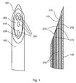
図1は、本発明の第1の実施例による針の遠位先端部を示す。前記針は、シャフト100及び細長い挿入物200を有する。シャフト100は、第1のベベル110を形成され、挿入物200は、第2のベベル210を形成され、両方のベベルが、同じ方向に向けられる。図1から見られるように、第1のベベル110は、第2のベベル210の角度とは異なる角度で形成される。
FIG. 1 shows the distal tip of a needle according to a first embodiment of the present invention. The needle has a
更に、シャフト100は、前記ベベルの側部に形成されたファセット120を持ち、前記ファセットは、前記先端の前及び横に向けられる。挿入物200は、ベベル210の面において開口端を持つチャネル220を含む。角度を付けられたベベルにより、チャネル220の開口端は、ポケット230の遠位端232及び近位端234を持つポケット230を与える。チャネル220内に、前面310を持つ光ファイバ300が、構成される。
Furthermore, the
図1の右図が、左図の中心線に沿った断面図であり、前記4つのチャネルの2つのみが前記断面図において可視であることに注意する。 Note that the right view of FIG. 1 is a cross-sectional view along the centerline of the left view, and only two of the four channels are visible in the cross-sectional view.
図2は、本発明による針の第2の実施例を示し、右図は、細長い挿入物200の遠位先端部のみを示し、左図は、前記挿入物の中心線に沿った断面図であるが、前記針のシャフト100と一緒に示す。この実施例において、チャネル220の対は、最も遠位に構成されたチャネルと前記挿入物の断面の真ん中との間のベベル210において形成される。これに応じて、光ファイバ300の先端は、第2のベベル210の面を越えて突き出している。光ファイバ300は、前記シャフトの第1のベベル110を越えて突き出さない。
FIG. 2 shows a second embodiment of the needle according to the invention, the right figure shows only the distal tip of the
更に、異なる角度が、図2に示される。前記針の長手軸とシャフト100の第1のベベル110との間に、鋭角である第1の角度'a'が形成される。前記長手軸と挿入物200の第2のベベル210との間に、第1の角度'a'より大きい鋭角である第2の角度'b'が形成される。更に、前記光ファイバの前面310は、好ましくは90度に近いが小さい第3の角度'c'を形成されることができる。
Further, different angles are shown in FIG. A first angle 'a' that is an acute angle is formed between the longitudinal axis of the needle and the
マルチルーメン挿入物を持つこのような針を製造するために、カニューレが使用される。前記挿入物は、典型的には、これらのルーメンに挿入されることができる前記ファイバの間の距離を規定する位置における明確に定義されたルーメンとともにプラスチック材料で作成される。前記ルーメンにおいて使用される前記ファイバは、典型的には、前記ファイバの端部における(部分)全内部反射が防がれるように真っ直ぐ又は穏やかな角度でのみ切断される。全内部反射が生じる場合、前記ファイバ端部において反射される光は、前記ファイバのクラッディングに行きつく。何の材料が前記ファイバを囲むかに依存して、この光の一部は、前記ファイバのコアに戻るように反射され、前記ファイバを離れることができる。拡散反射に対して、これは、大した問題ではないが、蛍光に対して、これは、大量の背景蛍光を引き起こす。これは、前記組織により生成される蛍光の検査を妨げる。 A cannula is used to produce such a needle with a multi-lumen insert. The insert is typically made of a plastic material with a well-defined lumen in a position that defines the distance between the fibers that can be inserted into these lumens. The fiber used in the lumen is typically cut only straight or at a gentle angle so that (partial) total internal reflection at the end of the fiber is prevented. When total internal reflection occurs, the light reflected at the end of the fiber reaches the cladding of the fiber. Depending on what material surrounds the fiber, a portion of this light is reflected back to the fiber core and can leave the fiber. For diffuse reflection this is not a big problem, but for fluorescence this causes a large amount of background fluorescence. This hinders examination of the fluorescence produced by the tissue.
前記遠位端における前記挿入物は、前記カニューレのベベルの角度より大きい角度で斜角をつけられる。このようにして、前記マルチルーメン内で前記ファイバをアセンブルする場合に、前記ファイバは、前記カニューレのベベルを越えて突き出すことなしに前記挿入物のベベルを越えていくらか突き出すことができる。これは、前記組織内の前記針の挿入特性に影響を与えないために重要である。 The insert at the distal end is beveled at an angle greater than the angle of the cannula bevel. In this way, when assembling the fiber within the multi-lumen, the fiber can protrude somewhat beyond the bevel of the insert without protruding beyond the bevel of the cannula. This is important because it does not affect the insertion characteristics of the needle in the tissue.
前記挿入物内で前記ファイバをアセンブルする最も単純な方法は、図1に描かれるように前記ポケットの始点に等しく前記ファイバ端部を配置することによる。拡散反射に対して、これは、可能なオプションであるが、蛍光に対して、これは好ましくない。蛍光検出に対して、光源と検出ファイバ端部との間の距離は、最適な信号を持つように小さくなくてはならない。これは、図3に示される測定から見られることができる。図3の真ん中に描かれるように、ファイバは、前記ベベル上にシフトして構成されたポケットA及びBに配置される。前記測定に対して、前記ファイバ端部は、前記ポケットにおいて、したがって前記ベベル面に対して、異なる位置にある。 The simplest way to assemble the fiber in the insert is by placing the fiber end equal to the start of the pocket as depicted in FIG. For diffuse reflection this is a possible option, but for fluorescence this is not preferred. For fluorescence detection, the distance between the light source and the end of the detection fiber must be small to have an optimal signal. This can be seen from the measurements shown in FIG. As depicted in the middle of FIG. 3, the fibers are placed in pockets A and B which are configured to be shifted on the bevel. For the measurement, the fiber end is in a different position in the pocket and thus relative to the bevel surface.
更なる観察は、前記2つのポケット、すなわちポケットA及びDが図4の場合のように互いに隣接して並べて構成される場合に行われることができる。前記ファイバが、前記ポケットの始点に実質的に等しい場合、前記ポケットの壁の遮蔽効果は、重大であり、より小さな信号を生じる。これは、図4の真ん中においてポケットAとDとの間のバーにより概略的に視覚化される。したがって、この場合、前記ファイバの間の距離は、両方が前記ポケットの始点を越えて同じ量を突き出す場合に変化しないが、前記信号は、前記ファイバが前記ポケットの側壁の低減効果のために、より多く突き出す場合に、より高くなる。したがって、蛍光の場合、前記ファイバ端部の少なくとも1つは、前記ポケットの始点を越えて突き出すべきである。有利には、前記ファイバ端部は、前記ポケットの始点を越えて前記ファイバの口径の半分以上突き出す。他の実施例において、前記ファイバ端部は、前記ポケットの始点を越えて前記ファイバの口径以上突き出す。 Further observations can be made when the two pockets, i.e. pockets A and D, are arranged side by side as in FIG. If the fiber is substantially equal to the starting point of the pocket, the shielding effect of the pocket wall is significant and produces a smaller signal. This is schematically visualized by a bar between pockets A and D in the middle of FIG. Thus, in this case, the distance between the fibers does not change if both protrude the same amount beyond the start of the pocket, but the signal is due to the reduction effect of the side walls of the pocket, The more it protrudes, the higher it becomes. Thus, in the case of fluorescence, at least one of the fiber ends should protrude beyond the starting point of the pocket. Advantageously, the fiber end protrudes more than half of the fiber diameter beyond the starting point of the pocket. In another embodiment, the fiber end protrudes beyond the starting point of the pocket beyond the aperture of the fiber.
前記挿入物は、大量生産で生産されることができる。真っ直ぐ切断されたファイバを生産することは、バッチにおいて行われることができる。前記マルチルーメン内にファイバをアセンブルすることは、良好に制御され、これらの針を大量生産に適合させることができる。更に、このアセンブル方法のため、幾分低いコストの針が保証されることができる。 The insert can be produced in mass production. Producing straight cut fibers can be done in batches. Assembling the fibers within the multi-lumen is well controlled and these needles can be adapted for mass production. Furthermore, because of this assembly method, a somewhat lower cost needle can be guaranteed.
図7は、本発明による針を製造する方法のステップを示すフローチャートである。前記方法に関して記されるステップは、主要なステップであり、これらの主要なステップは、複数のサブステップに分化又は分割されてもよいと理解されたい。更に、これらの主要なステップの間にサブステップが存在することもありうる。したがって、サブステップは、前記ステップが本発明による方法の原理の理解に対して重要である場合にのみ述べられる。 FIG. 7 is a flow chart showing the steps of the method for manufacturing a needle according to the present invention. It should be understood that the steps described with respect to the method are major steps, and these major steps may be differentiated or divided into multiple sub-steps. In addition, there may be substeps between these major steps. Thus, sub-steps are described only if said steps are important for understanding the principle of the method according to the invention.
ステップS1において、中空シャフトが製造され、このステップは、前記中空シャフトの長手軸に対して鋭角の第1の角度を持つ第1のベベルの形成を含む。 In step S1, a hollow shaft is manufactured, which includes forming a first bevel having a first angle that is acute with respect to the longitudinal axis of the hollow shaft.
ステップS2において、細長い挿入物が製造され、このステップは、前記長手軸に対して鋭角の第2の角度を持つ第2のベベルの形成と、光ファイバを収容する少なくとも1つのチャネルの形成とを含み、前記第2の角度は、前記第1の角度より大きい。 In step S2, an elongated insert is manufactured, which comprises forming a second bevel having a second angle that is acute with respect to the longitudinal axis, and forming at least one channel for receiving the optical fiber. The second angle is greater than the first angle.
ステップS3において、少なくとも1つのファイバが、チャネル内に配置及び固定される。前記少なくとも1つのファイバは、ポケットが前記細長い挿入物の前記第2のベベルにおいて前記チャネル開口端に形成されるように、前記少なくとも1つのチャネル内に配置されることができる。 In step S3, at least one fiber is placed and secured in the channel. The at least one fiber may be disposed in the at least one channel such that a pocket is formed at the channel open end at the second bevel of the elongated insert.
ステップS4において、前記細長い挿入物は、前記第2のベベル及び前記少なくとも1つのファイバの前面が前記中空シャフト内に配置される、すなわち、前記ファイバの前面が前記シャフトの前記第1のベベルの面を越えて突き出さないように、前記中空シャフト内に配置される。 In step S4, the elongate insert has the second bevel and the front surface of the at least one fiber disposed within the hollow shaft, ie, the front surface of the fiber is the surface of the first bevel of the shaft. It is arranged in the hollow shaft so as not to protrude beyond.
ステップS5において、前記細長い挿入物は、前記シャフトに対して着脱可能に固定される。好ましくは、これは、前記挿入物と前記針のホルダ部における前記シャフトとの間の解放可能接続により達成される。 In step S5, the elongated insert is detachably fixed to the shaft. Preferably this is achieved by a releasable connection between the insert and the shaft in the holder part of the needle.
図5に示されるように、ファイバ300を含む挿入物及びシャフト100を持つ前記針は、光学コンソールに接続されることができる。前記光学コンソールは、光がファイバ300の1つ又は複数を介して前記針の遠位端におけるベベル110に提供されることを可能にする光源410を含む。散乱光は、1つ又は複数のファイバ300により収集され、検出器420又は複数の検出器に向けてガイドされる。この"検出"ファイバにおいて測定される反射光の量は、探査される構造(例えば組織)の吸収及び散乱特性により決定される。データは、専用アルゴリズムを使用して処理ユニット400により処理されることができる。拡散反射測定に対して、前記光源又は前記検出器のいずれか又は両方の組み合わせは、波長選択性を提供しなくてはならない。例えば、光は、光源として機能する少なくとも1つのファイバを通して遠位端の外に結合されることができ、波長は、例えば500ないし1600nmでスイープされ、少なくとも1つの検出ファイバにより検出される光は、広帯域検出器に送られる。代わりに、広帯域光は、少なくとも1つの光源ファイバにより提供されることができ、少なくとも1つの検出ファイバにより検出される光は、波長選択検出器、例えば分光計に送られる。
As shown in FIG. 5, the insert with
拡散反射測定に関する詳細な議論に対して、R. Nachabe, B.H.W. Hendriks, A.E. Desjardins, M. van der Voort, M.B. van der Mark, and H.J.C.M. Sterenborg, "Estimation of lipid and water concentrations in scattering media with diffuse optical spectroscopy from 900 to 1600nm", J. Biomed. Opt. 15, 037015 (2010)を参照する。 R. Nachabe, BHW Hendriks, AE Desjardins, M. van der Voort, MB van der Mark, and HJCM Sterenborg, "Estimation of lipid and water concentrations in scattering media with diffuse optical spectroscopy from 900 to 1600 nm ", J. Biomed. Opt. 15, 037015 (2010).
蛍光測定に対して、前記コンソールは、1つ又は複数の検出ファイバを通して組織生成蛍光を検出しながら少なくとも1つの光源ファイバに励起光を提供することができなくてはならない。前記励起光源は、レーザ(例えば半導体レーザ)、発光ダイオード(LED)又はフィルタ水銀灯のようなフィルタ光源でありうる。一般に、前記励起光源により放射される波長は、検出されるべきである蛍光の波長の範囲より短い。前記励起光による前記検出器の起こりうるオーバロードを避けるために検出フィルタを使用して前記励起光をフィルタ除去することが好ましい。波長選択検出器、例えば分光計は、互いから区別される必要のある複数の蛍光エンティティが存在する場合に必要とされる。 For fluorescence measurements, the console must be able to provide excitation light to at least one light source fiber while detecting tissue-generated fluorescence through one or more detection fibers. The excitation light source may be a filter light source such as a laser (eg, a semiconductor laser), a light emitting diode (LED), or a filter mercury lamp. In general, the wavelength emitted by the excitation light source is shorter than the range of wavelengths of fluorescence that should be detected. Preferably, the excitation light is filtered out using a detection filter to avoid possible overload of the detector due to the excitation light. A wavelength selective detector, such as a spectrometer, is required when there are multiple fluorescent entities that need to be distinguished from each other.
蛍光測定が拡散反射測定と結合されるべきである場合、蛍光を測定するための励起光は、拡散反射に対する光と同じ光源ファイバに提供されることができる。これは、例えば、ファイバスイッチ、又はビームスプリッタ又は集束光学素子を持つ二色性ビーム結合器を使用することにより達成されることができる。代わりに、別のファイバが、蛍光励起光及び拡散反射測定に対する光を提供するのに使用されることができる。 If the fluorescence measurement is to be combined with a diffuse reflection measurement, the excitation light for measuring the fluorescence can be provided in the same light source fiber as the light for diffuse reflection. This can be achieved, for example, by using a fiber switch or a dichroic beam combiner with a beam splitter or focusing optics. Alternatively, separate fibers can be used to provide light for fluorescence excitation light and diffuse reflectance measurements.
拡散反射分光が、組織特性を抽出するように上に記載されているが、複数の光ファイバを使用することにより拡散光学断層撮影、差分経路長分光、ラマン分光のような他の光学的方法も、想定されることができる。更に、前記システムは、自己蛍光を見るだけの代わりに、造影剤が使用される場合に使用されることもできる。 Diffuse reflectance spectroscopy has been described above to extract tissue properties, but other optical methods such as diffuse optical tomography, differential path length spectroscopy, and Raman spectroscopy can be obtained by using multiple optical fibers. Can be envisioned. Furthermore, the system can also be used when contrast agents are used instead of just looking at autofluorescence.
本発明によると、以下のアルゴリズムが、異なる組織発色団、例えばヘモグロビン、酸化ヘモグロビン、水、脂肪等の散乱係数及び吸収係数のような光学的組織特性を得るのに使用されることができる。これらの特性は、正常な健康組織と病変(癌性)組織との間で異なる。 According to the present invention, the following algorithms can be used to obtain optical tissue properties such as scattering and absorption coefficients of different tissue chromophores, eg hemoglobin, oxyhemoglobin, water, fat etc. These properties differ between normal healthy tissue and diseased (cancerous) tissue.
可視及び近赤外範囲の吸収を支配する正常組織の主要な吸収成分は、血液(すなわちヘモグロビン)、水及び脂肪である。図6において、波長の関数としてこれらの発色団の吸収係数が、示されている。血液が可視範囲の吸収を支配し、水及び脂肪が近赤外範囲において支配することに注意する。 The main absorbing components of normal tissue that dominate absorption in the visible and near infrared range are blood (ie hemoglobin), water and fat. In FIG. 6, the absorption coefficients of these chromophores as a function of wavelength are shown. Note that blood dominates absorption in the visible range, and water and fat dominate in the near infrared range.
全吸収係数は、例えば血液、水及び脂肪の吸収係数(したがって各成分に対して体積分率で乗算された図6に示されたものの値)の線形結合である。散乱に対するべき法則を使用しながらこのモデルを測定結果にフィッティングすることにより(R. Nachabe, B.H.W. Hendriks, A.E. Desjardins, M. van der Voort, M.B. van der Mark, and H.J.C.M. Sterenborg, "Estimation of lipid and water concentrations in scattering media with diffuse optical spectroscopy from 900 to 1600nm", J. Biomed. Opt. 15, 037015 (2010)を参照)、我々は、血液、水及び脂肪の体積分率及び散乱係数を決定することができる。この方法を用いて、我々は、測定されたスペクトルを、異なる組織を区別するのに使用されることができる生理パラメータに変換することができる。 The total absorption coefficient is, for example, a linear combination of the absorption coefficients of blood, water and fat (thus the values of those shown in FIG. 6 multiplied by the volume fraction for each component). By fitting this model to the measurement results using the power law for scattering (R. Nachabe, BHW Hendriks, AE Desjardins, M. van der Voort, MB van der Mark, and HJCM Sterenborg, "Estimation of lipid and water concentration in scattering media with diffuse optical spectroscopy from 900 to 1600nm ", J. Biomed. Opt. 15, 037015 (2010)), we can determine the volume fraction and scattering coefficient of blood, water and fat. it can. Using this method, we can convert the measured spectrum into physiological parameters that can be used to distinguish different tissues.
スペクトルにおける差異を区別する他の方法は、主成分分析を使用することによる。この方法は、スペクトルにおける差異の分類を可能にし、組織間の区別を可能にする。スペクトルからフィーチャを抽出することも可能である。 Another way to distinguish differences in the spectrum is by using principal component analysis. This method allows for the classification of differences in the spectrum and allows differentiation between tissues. It is also possible to extract features from the spectrum.
前記測定された蛍光から固有蛍光を抽出する方法は、例えばZhang et al., Optics Letters 25 (2000) p1451において見つけられることができる。 A method for extracting intrinsic fluorescence from the measured fluorescence can be found, for example, in Zhang et al., Optics Letters 25 (2000) p1451.
本発明による針は、低背部痛介入のような最小侵襲針介入又は癌診断の分野における生検又は前記針の周りの組織特性が必要とされる場合に使用されることができる。 The needles according to the present invention can be used when minimally invasive needle interventions such as low back pain interventions or biopsies in the field of cancer diagnosis or tissue properties around the needles are required.
本発明は、図面及び先行する記載において詳細に図示及び説明されているが、このような図示及び説明は、限定的ではなく説明用又は典型であると見なされるべきであり、本発明は、開示された実施例に限定されない。開示された実施例に対する他の変形例は、図面、開示及び添付の請求項の検討から、請求された発明を実施する際に当業者により理解及び達成されることができる。 While the invention has been illustrated and described in detail in the drawings and foregoing description, such illustration and description are to be considered illustrative or exemplary and not restrictive; the invention is disclosed. It is not limited to the embodiment described. Other variations to the disclosed embodiments can be understood and achieved by those skilled in the art in practicing the claimed invention, from a study of the drawings, the disclosure, and the appended claims.
請求項において、単語"有する"は、他の要素又はステップを除外せず、不定冠詞"ある"は、複数を除外しない。単一のプロセッサ又は他のユニットが、請求項に記載された複数のアイテムの機能を満たしてもよい。特定の方策が相互に異なる従属請求項に記載されているという単なる事実は、これらの方策の組み合わせが有利に使用されることができないことを示さない。コンピュータプログラムは、他のハードウェアと一緒に又は一部として提供される光記憶媒体又は半導体媒体のような適切な媒体に記憶/分散されることができるか、インターネット又は他の有線若しくは無線電気通信システムを介する他の形式で分散されてもよい。請求項内の参照符号は、範囲を限定すると解釈されるべきではない。 In the claims, the word “comprising” does not exclude other elements or steps, and the indefinite article “a” does not exclude a plurality. A single processor or other unit may fulfill the functions of several items recited in the claims. The mere fact that certain measures are recited in mutually different dependent claims does not indicate that a combination of these measures cannot be used to advantage. The computer program can be stored / distributed on a suitable medium such as an optical storage medium or a semiconductor medium provided together with or as part of other hardware, the Internet or other wired or wireless telecommunications It may be distributed in other ways through the system. Any reference signs in the claims should not be construed as limiting the scope.
100:中空シャフト
110:第1のベベル
120:ホルダ部
130:コネクタ
200:細長い挿入物
210:第2のベベル
220:チャネル
230:ポケット
232:ポケットの遠位端
234:ポケットの近位端
300:光ファイバ
310:前面
400:処理ユニット
410:光源
420:光検出器
430:モニタ
100: hollow shaft 110: first bevel 120: holder part 130: connector 200: elongated insert 210: second bevel 220: channel 230: pocket 232:
Claims (15)
細長い挿入物であって、前記細長い挿入物の遠位端部に形成され、前記長手軸に対して鋭角の第2の角度を持つ第2のベベルを持ち、前記第1の角度が前記第2の角度より小さい前記細長い挿入物と、
前記細長い挿入物内に構成された光ファイバと、
を有する針において、
前記細長い挿入物が、前記中空シャフト内に構成及び固定され、前記第2のベベル及び前記ファイバの前面が、前記中空シャフト内に配置される、
針。 A hollow shaft having a longitudinal axis and a first bevel formed at a distal end of the hollow shaft and having a first acute angle with respect to the longitudinal axis;
An elongate insert having a second bevel formed at a distal end of the elongate insert and having an acute second angle with respect to the longitudinal axis, the first angle being the second Said elongated insert smaller than an angle of
An optical fiber configured within the elongated insert;
In a needle having
The elongated insert is configured and secured within the hollow shaft, and the second bevel and the front surface of the fiber are disposed within the hollow shaft.
needle.
請求項1ないし8の何れか一項に記載の針と、
光源、光検出器及び前記光検出器により提供される信号を処理する処理ユニットを含むコンソールと、
を有するシステム。 In the system for tissue examination,
A needle according to any one of claims 1 to 8,
A console comprising a light source, a light detector and a processing unit for processing a signal provided by the light detector;
Having a system.
中空シャフトを製造するステップであって、前記中空シャフトの長手軸に対して鋭角の第1の角度を持つ第1のベベルを形成することを含むステップと、
細長い挿入物を製造するステップであって、前記長手軸に対して鋭角の第2の角度を持つ第2のベベルを形成すること及び前記第2のベベルにおいて開口端を持つ少なくとも1つのチャネルを形成することを含み、前記第2の角度が前記第1の角度より大きいステップと、
それぞれのチャネルにおいて少なくとも1つの光ファイバを配置及び固定するステップと、
前記第2のベベル及び前記少なくとも1つの光ファイバの前面が前記中空シャフト内に配置されるように前記中空シャフト内に前記細長い挿入物を配置及び固定するステップと、
を有する方法。 A method for manufacturing the needle according to any one of claims 1 to 8,
Producing a hollow shaft comprising forming a first bevel having a first acute angle with respect to the longitudinal axis of the hollow shaft;
Manufacturing an elongated insert, forming a second bevel having an acute second angle with respect to the longitudinal axis and forming at least one channel having an open end at the second bevel; And wherein the second angle is greater than the first angle;
Placing and securing at least one optical fiber in each channel;
Placing and securing the elongate insert in the hollow shaft such that a front surface of the second bevel and the at least one optical fiber is disposed in the hollow shaft;
Having a method.
Applications Claiming Priority (3)
| Application Number | Priority Date | Filing Date | Title |
|---|---|---|---|
| EP11171667.6 | 2011-06-28 | ||
| EP11171667 | 2011-06-28 | ||
| PCT/IB2012/052978 WO2013001394A1 (en) | 2011-06-28 | 2012-06-13 | Needle with an optical fiber integrated in an elongated insert |
Publications (2)
| Publication Number | Publication Date |
|---|---|
| JP2014518118A true JP2014518118A (en) | 2014-07-28 |
| JP2014518118A5 JP2014518118A5 (en) | 2015-07-09 |
Family
ID=46508124
Family Applications (1)
| Application Number | Title | Priority Date | Filing Date |
|---|---|---|---|
| JP2014517989A Withdrawn JP2014518118A (en) | 2011-06-28 | 2012-06-13 | Needle with optical fiber integrated into an elongated insert |
Country Status (7)
| Country | Link |
|---|---|
| US (1) | US20140121538A1 (en) |
| EP (1) | EP2725965A1 (en) |
| JP (1) | JP2014518118A (en) |
| CN (1) | CN103648368A (en) |
| BR (1) | BR112013033225A2 (en) |
| RU (1) | RU2014102498A (en) |
| WO (1) | WO2013001394A1 (en) |
Cited By (1)
| Publication number | Priority date | Publication date | Assignee | Title |
|---|---|---|---|---|
| JP2014518390A (en) * | 2011-06-28 | 2014-07-28 | コーニンクレッカ フィリップス エヌ ヴェ | Apparatus for optical analysis of relevant tissue samples |
Families Citing this family (17)
| Publication number | Priority date | Publication date | Assignee | Title |
|---|---|---|---|---|
| GB201301280D0 (en) * | 2013-01-24 | 2013-03-06 | Univ St Andrews | Optical apparatus for use with a medical imager |
| WO2014132110A1 (en) * | 2013-02-27 | 2014-09-04 | Koninklijke Philips N.V. | Optical guided vacuum assisted biopsy device |
| US9854961B2 (en) | 2013-04-03 | 2018-01-02 | Koninklijke Philips N.V. | Photonic needle with optimal bevel angle |
| WO2014162242A1 (en) | 2013-04-03 | 2014-10-09 | Koninklijke Philips N.V. | Photonic needle |
| US10299826B2 (en) | 2013-12-18 | 2019-05-28 | Sensoptic Sa | Needle for invasive medical use and needle assembly |
| WO2015121147A1 (en) | 2014-02-14 | 2015-08-20 | Koninklijke Philips N.V. | Photonic device with smooth tip and improved light output |
| US10405838B2 (en) * | 2014-08-28 | 2019-09-10 | Koninklijke Philips N.V. | Side-looking lung biopsy device |
| TWI546071B (en) | 2015-09-24 | 2016-08-21 | 曾效參 | Optical Needle |
| TW201713060A (en) | 2015-09-24 | 2017-04-01 | 曾效參 | Lightguide assembly |
| JP6807918B2 (en) * | 2015-09-24 | 2021-01-06 | ベクトン・ディキンソン・アンド・カンパニーBecton, Dickinson And Company | 5 oblique needles of blood collection device |
| TWI595870B (en) | 2015-09-24 | 2017-08-21 | 曾效參 | Optical needle with lightguide groove and method for preparation thereof |
| JP6475367B2 (en) * | 2016-01-25 | 2019-02-27 | 富士フイルム株式会社 | Inserts and attachment members |
| US10393652B2 (en) * | 2016-01-26 | 2019-08-27 | Tubitak | Portable optical apparatus for diffuse reflectance spectroscopy |
| WO2018206598A1 (en) * | 2017-05-08 | 2018-11-15 | Danmarks Tekniske Universitet | A needle and a method of making a needle |
| JP6752373B2 (en) * | 2017-09-15 | 2020-09-09 | 富士フイルム株式会社 | Inserts, optical inserts and photoacoustic measuring devices |
| CN110522958A (en) * | 2019-09-30 | 2019-12-03 | 武汉中科科理光电技术有限公司 | Photo-electric intelligent syringe |
| FR3130542A1 (en) * | 2021-12-21 | 2023-06-23 | Bruno Anastasie | Medical instrument and system comprising such an instrument |
Family Cites Families (7)
| Publication number | Priority date | Publication date | Assignee | Title |
|---|---|---|---|---|
| US4566438A (en) | 1984-10-05 | 1986-01-28 | Liese Grover J | Fiber-optic stylet for needle tip localization |
| US5280788A (en) * | 1991-02-26 | 1994-01-25 | Massachusetts Institute Of Technology | Devices and methods for optical diagnosis of tissue |
| US6564087B1 (en) * | 1991-04-29 | 2003-05-13 | Massachusetts Institute Of Technology | Fiber optic needle probes for optical coherence tomography imaging |
| US5526112A (en) * | 1993-03-05 | 1996-06-11 | Sahagen; Armen N. | Probe for monitoring a fluid medium |
| ATE278352T1 (en) * | 1997-08-09 | 2004-10-15 | Roche Diagnostics Gmbh | ANALYZING DEVICE FOR IN-VIVO ANALYSIS IN A PATIENT'S BODY |
| US20110251494A1 (en) * | 2008-11-19 | 2011-10-13 | Koninklijke Philips Electronics N.V. | Needle with optical fibers |
| WO2010058302A1 (en) * | 2008-11-19 | 2010-05-27 | Koninklijke Philips Electronics N.V. | Needle with integrated fibers |
-
2012
- 2012-06-13 RU RU2014102498/14A patent/RU2014102498A/en not_active Application Discontinuation
- 2012-06-13 US US14/127,692 patent/US20140121538A1/en not_active Abandoned
- 2012-06-13 EP EP12735025.4A patent/EP2725965A1/en not_active Withdrawn
- 2012-06-13 CN CN201280031573.XA patent/CN103648368A/en active Pending
- 2012-06-13 JP JP2014517989A patent/JP2014518118A/en not_active Withdrawn
- 2012-06-13 BR BR112013033225A patent/BR112013033225A2/en not_active IP Right Cessation
- 2012-06-13 WO PCT/IB2012/052978 patent/WO2013001394A1/en active Application Filing
Cited By (1)
| Publication number | Priority date | Publication date | Assignee | Title |
|---|---|---|---|---|
| JP2014518390A (en) * | 2011-06-28 | 2014-07-28 | コーニンクレッカ フィリップス エヌ ヴェ | Apparatus for optical analysis of relevant tissue samples |
Also Published As
| Publication number | Publication date |
|---|---|
| BR112013033225A2 (en) | 2017-03-01 |
| WO2013001394A1 (en) | 2013-01-03 |
| CN103648368A (en) | 2014-03-19 |
| US20140121538A1 (en) | 2014-05-01 |
| RU2014102498A (en) | 2015-08-10 |
| EP2725965A1 (en) | 2014-05-07 |
Similar Documents
| Publication | Publication Date | Title |
|---|---|---|
| JP2014518118A (en) | Needle with optical fiber integrated into an elongated insert | |
| JP6076989B2 (en) | Medical probe with multi-fiber lumen | |
| JP6129179B2 (en) | Needle device having an optical fiber integrated in a movable insert | |
| US11406367B2 (en) | System with photonic biopsy device for obtaining pathological information | |
| EP2725967B1 (en) | An apparatus for optical analysis of an associated tissue sample | |
| RU2639037C2 (en) | Biopsy needle with large interfiber distance at tip | |
| JP2010511463A (en) | Method for obtaining optical properties of tissue | |
| US10405838B2 (en) | Side-looking lung biopsy device | |
| CN107635497B (en) | Optical tissue feedback device for electrosurgical devices | |
| WO2015121147A1 (en) | Photonic device with smooth tip and improved light output | |
| WO2015121115A1 (en) | Photonic device with smooth tip and improved light output |
Legal Events
| Date | Code | Title | Description |
|---|---|---|---|
| A521 | Request for written amendment filed |
Free format text: JAPANESE INTERMEDIATE CODE: A523 Effective date: 20150520 |
|
| A621 | Written request for application examination |
Free format text: JAPANESE INTERMEDIATE CODE: A621 Effective date: 20150520 |
|
| A761 | Written withdrawal of application |
Free format text: JAPANESE INTERMEDIATE CODE: A761 Effective date: 20160208 |