JP2014514097A - Medicinal module with automatic reservoir engagement and locking mechanism - Google Patents
Medicinal module with automatic reservoir engagement and locking mechanism Download PDFInfo
- Publication number
- JP2014514097A JP2014514097A JP2014505618A JP2014505618A JP2014514097A JP 2014514097 A JP2014514097 A JP 2014514097A JP 2014505618 A JP2014505618 A JP 2014505618A JP 2014505618 A JP2014505618 A JP 2014505618A JP 2014514097 A JP2014514097 A JP 2014514097A
- Authority
- JP
- Japan
- Prior art keywords
- module
- needle guard
- needle
- drug
- secondary packaging
- Prior art date
- Legal status (The legal status is an assumption and is not a legal conclusion. Google has not performed a legal analysis and makes no representation as to the accuracy of the status listed.)
- Pending
Links
Images


Classifications
-
- A—HUMAN NECESSITIES
- A61—MEDICAL OR VETERINARY SCIENCE; HYGIENE
- A61M—DEVICES FOR INTRODUCING MEDIA INTO, OR ONTO, THE BODY; DEVICES FOR TRANSDUCING BODY MEDIA OR FOR TAKING MEDIA FROM THE BODY; DEVICES FOR PRODUCING OR ENDING SLEEP OR STUPOR
- A61M5/00—Devices for bringing media into the body in a subcutaneous, intra-vascular or intramuscular way; Accessories therefor, e.g. filling or cleaning devices, arm-rests
- A61M5/178—Syringes
- A61M5/24—Ampoule syringes, i.e. syringes with needle for use in combination with replaceable ampoules or carpules, e.g. automatic
- A61M5/2448—Ampoule syringes, i.e. syringes with needle for use in combination with replaceable ampoules or carpules, e.g. automatic comprising means for injection of two or more media, e.g. by mixing
-
- A—HUMAN NECESSITIES
- A61—MEDICAL OR VETERINARY SCIENCE; HYGIENE
- A61M—DEVICES FOR INTRODUCING MEDIA INTO, OR ONTO, THE BODY; DEVICES FOR TRANSDUCING BODY MEDIA OR FOR TAKING MEDIA FROM THE BODY; DEVICES FOR PRODUCING OR ENDING SLEEP OR STUPOR
- A61M5/00—Devices for bringing media into the body in a subcutaneous, intra-vascular or intramuscular way; Accessories therefor, e.g. filling or cleaning devices, arm-rests
- A61M5/002—Packages specially adapted therefor, e.g. for syringes or needles, kits for diabetics
-
- A—HUMAN NECESSITIES
- A61—MEDICAL OR VETERINARY SCIENCE; HYGIENE
- A61M—DEVICES FOR INTRODUCING MEDIA INTO, OR ONTO, THE BODY; DEVICES FOR TRANSDUCING BODY MEDIA OR FOR TAKING MEDIA FROM THE BODY; DEVICES FOR PRODUCING OR ENDING SLEEP OR STUPOR
- A61M5/00—Devices for bringing media into the body in a subcutaneous, intra-vascular or intramuscular way; Accessories therefor, e.g. filling or cleaning devices, arm-rests
- A61M5/178—Syringes
- A61M5/31—Details
- A61M5/32—Needles; Details of needles pertaining to their connection with syringe or hub; Accessories for bringing the needle into, or holding the needle on, the body; Devices for protection of needles
- A61M5/3205—Apparatus for removing or disposing of used needles or syringes, e.g. containers; Means for protection against accidental injuries from used needles
- A61M5/321—Means for protection against accidental injuries by used needles
- A61M5/3243—Means for protection against accidental injuries by used needles being axially-extensible, e.g. protective sleeves coaxially slidable on the syringe barrel
- A61M5/326—Fully automatic sleeve extension, i.e. in which triggering of the sleeve does not require a deliberate action by the user
-
- A—HUMAN NECESSITIES
- A61—MEDICAL OR VETERINARY SCIENCE; HYGIENE
- A61M—DEVICES FOR INTRODUCING MEDIA INTO, OR ONTO, THE BODY; DEVICES FOR TRANSDUCING BODY MEDIA OR FOR TAKING MEDIA FROM THE BODY; DEVICES FOR PRODUCING OR ENDING SLEEP OR STUPOR
- A61M5/00—Devices for bringing media into the body in a subcutaneous, intra-vascular or intramuscular way; Accessories therefor, e.g. filling or cleaning devices, arm-rests
- A61M5/178—Syringes
- A61M5/31—Details
- A61M5/32—Needles; Details of needles pertaining to their connection with syringe or hub; Accessories for bringing the needle into, or holding the needle on, the body; Devices for protection of needles
- A61M5/3294—Needles; Details of needles pertaining to their connection with syringe or hub; Accessories for bringing the needle into, or holding the needle on, the body; Devices for protection of needles comprising means for injection of two or more media, e.g. by mixing
-
- A—HUMAN NECESSITIES
- A61—MEDICAL OR VETERINARY SCIENCE; HYGIENE
- A61M—DEVICES FOR INTRODUCING MEDIA INTO, OR ONTO, THE BODY; DEVICES FOR TRANSDUCING BODY MEDIA OR FOR TAKING MEDIA FROM THE BODY; DEVICES FOR PRODUCING OR ENDING SLEEP OR STUPOR
- A61M5/00—Devices for bringing media into the body in a subcutaneous, intra-vascular or intramuscular way; Accessories therefor, e.g. filling or cleaning devices, arm-rests
- A61M5/178—Syringes
- A61M2005/1787—Syringes for sequential delivery of fluids, e.g. first medicament and then flushing liquid
-
- A—HUMAN NECESSITIES
- A61—MEDICAL OR VETERINARY SCIENCE; HYGIENE
- A61M—DEVICES FOR INTRODUCING MEDIA INTO, OR ONTO, THE BODY; DEVICES FOR TRANSDUCING BODY MEDIA OR FOR TAKING MEDIA FROM THE BODY; DEVICES FOR PRODUCING OR ENDING SLEEP OR STUPOR
- A61M5/00—Devices for bringing media into the body in a subcutaneous, intra-vascular or intramuscular way; Accessories therefor, e.g. filling or cleaning devices, arm-rests
- A61M5/178—Syringes
- A61M5/20—Automatic syringes, e.g. with automatically actuated piston rod, with automatic needle injection, filling automatically
- A61M2005/2073—Automatic syringes, e.g. with automatically actuated piston rod, with automatic needle injection, filling automatically preventing premature release, e.g. by making use of a safety lock
-
- A—HUMAN NECESSITIES
- A61—MEDICAL OR VETERINARY SCIENCE; HYGIENE
- A61M—DEVICES FOR INTRODUCING MEDIA INTO, OR ONTO, THE BODY; DEVICES FOR TRANSDUCING BODY MEDIA OR FOR TAKING MEDIA FROM THE BODY; DEVICES FOR PRODUCING OR ENDING SLEEP OR STUPOR
- A61M5/00—Devices for bringing media into the body in a subcutaneous, intra-vascular or intramuscular way; Accessories therefor, e.g. filling or cleaning devices, arm-rests
- A61M5/178—Syringes
- A61M5/31—Details
- A61M5/32—Needles; Details of needles pertaining to their connection with syringe or hub; Accessories for bringing the needle into, or holding the needle on, the body; Devices for protection of needles
- A61M5/3205—Apparatus for removing or disposing of used needles or syringes, e.g. containers; Means for protection against accidental injuries from used needles
- A61M5/321—Means for protection against accidental injuries by used needles
- A61M5/3243—Means for protection against accidental injuries by used needles being axially-extensible, e.g. protective sleeves coaxially slidable on the syringe barrel
- A61M5/326—Fully automatic sleeve extension, i.e. in which triggering of the sleeve does not require a deliberate action by the user
- A61M2005/3267—Biased sleeves where the needle is uncovered by insertion of the needle into a patient's body
-
- A—HUMAN NECESSITIES
- A61—MEDICAL OR VETERINARY SCIENCE; HYGIENE
- A61M—DEVICES FOR INTRODUCING MEDIA INTO, OR ONTO, THE BODY; DEVICES FOR TRANSDUCING BODY MEDIA OR FOR TAKING MEDIA FROM THE BODY; DEVICES FOR PRODUCING OR ENDING SLEEP OR STUPOR
- A61M2205/00—General characteristics of the apparatus
- A61M2205/58—Means for facilitating use, e.g. by people with impaired vision
- A61M2205/581—Means for facilitating use, e.g. by people with impaired vision by audible feedback
-
- A—HUMAN NECESSITIES
- A61—MEDICAL OR VETERINARY SCIENCE; HYGIENE
- A61M—DEVICES FOR INTRODUCING MEDIA INTO, OR ONTO, THE BODY; DEVICES FOR TRANSDUCING BODY MEDIA OR FOR TAKING MEDIA FROM THE BODY; DEVICES FOR PRODUCING OR ENDING SLEEP OR STUPOR
- A61M2205/00—General characteristics of the apparatus
- A61M2205/58—Means for facilitating use, e.g. by people with impaired vision
- A61M2205/582—Means for facilitating use, e.g. by people with impaired vision by tactile feedback
-
- A—HUMAN NECESSITIES
- A61—MEDICAL OR VETERINARY SCIENCE; HYGIENE
- A61M—DEVICES FOR INTRODUCING MEDIA INTO, OR ONTO, THE BODY; DEVICES FOR TRANSDUCING BODY MEDIA OR FOR TAKING MEDIA FROM THE BODY; DEVICES FOR PRODUCING OR ENDING SLEEP OR STUPOR
- A61M2205/00—General characteristics of the apparatus
- A61M2205/58—Means for facilitating use, e.g. by people with impaired vision
- A61M2205/583—Means for facilitating use, e.g. by people with impaired vision by visual feedback
- A61M2205/584—Means for facilitating use, e.g. by people with impaired vision by visual feedback having a color code
-
- A—HUMAN NECESSITIES
- A61—MEDICAL OR VETERINARY SCIENCE; HYGIENE
- A61M—DEVICES FOR INTRODUCING MEDIA INTO, OR ONTO, THE BODY; DEVICES FOR TRANSDUCING BODY MEDIA OR FOR TAKING MEDIA FROM THE BODY; DEVICES FOR PRODUCING OR ENDING SLEEP OR STUPOR
- A61M5/00—Devices for bringing media into the body in a subcutaneous, intra-vascular or intramuscular way; Accessories therefor, e.g. filling or cleaning devices, arm-rests
- A61M5/178—Syringes
- A61M5/24—Ampoule syringes, i.e. syringes with needle for use in combination with replaceable ampoules or carpules, e.g. automatic
- A61M5/2455—Ampoule syringes, i.e. syringes with needle for use in combination with replaceable ampoules or carpules, e.g. automatic with sealing means to be broken or opened
- A61M5/2466—Ampoule syringes, i.e. syringes with needle for use in combination with replaceable ampoules or carpules, e.g. automatic with sealing means to be broken or opened by piercing without internal pressure increase
-
- A—HUMAN NECESSITIES
- A61—MEDICAL OR VETERINARY SCIENCE; HYGIENE
- A61M—DEVICES FOR INTRODUCING MEDIA INTO, OR ONTO, THE BODY; DEVICES FOR TRANSDUCING BODY MEDIA OR FOR TAKING MEDIA FROM THE BODY; DEVICES FOR PRODUCING OR ENDING SLEEP OR STUPOR
- A61M5/00—Devices for bringing media into the body in a subcutaneous, intra-vascular or intramuscular way; Accessories therefor, e.g. filling or cleaning devices, arm-rests
- A61M5/178—Syringes
- A61M5/31—Details
- A61M5/3146—Priming, e.g. purging, reducing backlash or clearance
-
- A—HUMAN NECESSITIES
- A61—MEDICAL OR VETERINARY SCIENCE; HYGIENE
- A61M—DEVICES FOR INTRODUCING MEDIA INTO, OR ONTO, THE BODY; DEVICES FOR TRANSDUCING BODY MEDIA OR FOR TAKING MEDIA FROM THE BODY; DEVICES FOR PRODUCING OR ENDING SLEEP OR STUPOR
- A61M5/00—Devices for bringing media into the body in a subcutaneous, intra-vascular or intramuscular way; Accessories therefor, e.g. filling or cleaning devices, arm-rests
- A61M5/178—Syringes
- A61M5/31—Details
- A61M5/315—Pistons; Piston-rods; Guiding, blocking or restricting the movement of the rod or piston; Appliances on the rod for facilitating dosing ; Dosing mechanisms
- A61M5/31533—Dosing mechanisms, i.e. setting a dose
-
- A—HUMAN NECESSITIES
- A61—MEDICAL OR VETERINARY SCIENCE; HYGIENE
- A61M—DEVICES FOR INTRODUCING MEDIA INTO, OR ONTO, THE BODY; DEVICES FOR TRANSDUCING BODY MEDIA OR FOR TAKING MEDIA FROM THE BODY; DEVICES FOR PRODUCING OR ENDING SLEEP OR STUPOR
- A61M5/00—Devices for bringing media into the body in a subcutaneous, intra-vascular or intramuscular way; Accessories therefor, e.g. filling or cleaning devices, arm-rests
- A61M5/178—Syringes
- A61M5/31—Details
- A61M5/32—Needles; Details of needles pertaining to their connection with syringe or hub; Accessories for bringing the needle into, or holding the needle on, the body; Devices for protection of needles
- A61M5/3205—Apparatus for removing or disposing of used needles or syringes, e.g. containers; Means for protection against accidental injuries from used needles
- A61M5/321—Means for protection against accidental injuries by used needles
- A61M5/3243—Means for protection against accidental injuries by used needles being axially-extensible, e.g. protective sleeves coaxially slidable on the syringe barrel
- A61M5/3271—Means for protection against accidental injuries by used needles being axially-extensible, e.g. protective sleeves coaxially slidable on the syringe barrel with guiding tracks for controlled sliding of needle protective sleeve from needle exposing to needle covering position
- A61M5/3272—Means for protection against accidental injuries by used needles being axially-extensible, e.g. protective sleeves coaxially slidable on the syringe barrel with guiding tracks for controlled sliding of needle protective sleeve from needle exposing to needle covering position having projections following labyrinth paths
Abstract
少なくとも二つの薬剤を一緒に送達するための注射システム用モジュールが開示され、ここで、一次薬剤を含有する一次送達デバイスは、二次薬剤の単回用量を含有するモジュールを受け入れ、そしてここで、両方の薬剤は中空針を通して送達される。モジュール(80)は、使用者が、二次薬剤を含有するリザーバを手動で係合することを要求しない。その代わりに、ニードルガード(82)が後退されるとき、付勢部材はリザーバ自動的に起動する。ニードルガードは注射前後の偶発的な針刺しを防ぎ、そして用量送達後にロックする。拘束機能は、トリガーロックされた位置において、ニードルガードがデバイスに対して動くことを防ぐためにモジュール上に存在する。 A module for an injection system for delivering at least two agents together is disclosed, wherein a primary delivery device containing a primary agent accepts a module containing a single dose of a secondary agent, and wherein Both drugs are delivered through a hollow needle. Module (80) does not require the user to manually engage the reservoir containing the secondary drug. Instead, when the needle guard (82) is retracted, the biasing member automatically activates the reservoir. The needle guard prevents accidental needle sticks before and after injection and locks after dose delivery. A restraining function is present on the module to prevent the needle guard from moving relative to the device in the trigger locked position.
Description
この発明は、単一用量設定機構及び単一投薬インターフェースのみを有するデバイスを使用して、別々のリザーバから少なくとも二つの薬物作用物質を送達する薬用デバイス及び方法に関する。この発明は、その中で薬用デバイスが保存されそして使用者に輸送される二次パッケージングにも関する。使用者によって開始される単一送達手順によって、第二の薬物作用物質の使用者が設定不可の用量、及び第一の薬物作用物質の可変設定用量が患者に送達されることになる。薬物作用物質は、各々が独立した(単一薬物化合物の)又はプレミックスされた(共製剤化多剤薬物化合物(co-formulated multiple drug compounds))薬物作用物質を含有する、二つ又はそれ以上のリザーバ、容器又はパッケージング中で利用され得る。ニードルガードの起動によって、一次薬剤の設定された用量及び二次薬剤の単一の固定された用量が注射されることを可能にするために、二次薬剤のリザーバが投薬導管と自動的に係合されることになる。このように、第二の薬物作用物質を投薬するためのモジュールを使用者が手動で選択し又は設定する必要がない薬用モジュールが提示される。薬用モジュール用の二次パッケージングは、ニードルガードの偶発的なトリガーを防ぐように設計される。 The present invention relates to a medicinal device and method for delivering at least two drug agents from separate reservoirs using a device having only a single dose setting mechanism and a single dosing interface. The invention also relates to secondary packaging in which medicinal devices are stored and transported to the user. A single delivery procedure initiated by the user will deliver a non-settable dose for the user of the second drug agent and a variable set dose of the first drug agent to the patient. Two or more drug agents, each containing independent (single drug compound) or premixed (co-formulated multiple drug compounds) drug agents In reservoirs, containers or packaging. Activation of the needle guard automatically engages the secondary drug reservoir with the dosing conduit to allow a set dose of the primary drug and a single fixed dose of the secondary drug to be injected. Will be combined. Thus, a medicated module is presented that does not require the user to manually select or set a module for dispensing the second drug agent. Secondary packaging for the medicated module is designed to prevent accidental triggering of the needle guard.
或る病状では、一つ又はそれより以上の異なる薬剤を用いて治療することが要求される。幾つかの薬物化合物は、最適な治療用量を送達するために、互いに対して特定の関係において送達される必要がある。この発明は、併用療法が望ましい場合、但し、限定するものではないが、安定性、不充分な治療性能及び毒性学のような理由で、単独配合においては不可能である場合に特に便益があるものである。 Certain medical conditions require treatment with one or more different drugs. Some drug compounds need to be delivered in a specific relationship to each other in order to deliver the optimal therapeutic dose. This invention is particularly beneficial when combination therapy is desired, but is not limited to such reasons that stability, inadequate therapeutic performance and toxicology are not possible in a single formulation. Is.
例えば、幾つかの場合において、糖尿病を、持続性インスリンを用いて及びプログルカゴン遺伝子の転写産物に由来するグルカゴン−様ペプチド−1(GLP−1)を用いて治療することは便益があるであろう。GLP−1は体内において見出され、そして腸のL細胞によって消化管ホルモンとして分泌される。GLP−1は、それ(及びその類似体)を糖尿病の有望な治療として広汎な研究対象とする幾つかの生理学的性質を有する。 For example, in some cases it is beneficial to treat diabetes with persistent insulin and with glucagon-like peptide-1 (GLP-1) derived from the transcript of the proglucagon gene. Let's go. GLP-1 is found in the body and is secreted as a gut hormone by intestinal L cells. GLP-1 has several physiological properties that make it (and its analogs) an extensive study subject as a promising treatment for diabetes.
二つの薬剤又は活性作用物質を同時に送達するとき、多くの潜在的問題がある。二つの活性作用物質は、調剤の長期間の寿命保存中に互いに相互作用し得る。従って、活性成分を別々に保存し、そして例えば、注射、無針注射、ポンプ又は吸入などの送達の時点でのみ、それらを組み合わせることは有利であり得る。しかしながら、二つの作用物質を組み合わせるためのプロセスは、使用者が信頼して、繰り返してそして安全に実行するために簡単でかつ便利であることが必要である。 There are many potential problems when delivering two drugs or active agents simultaneously. The two active agents can interact with each other during the long-term shelf life of the formulation. Thus, it may be advantageous to store the active ingredients separately and combine them only at the time of delivery, eg, injection, needleless injection, pump or inhalation. However, the process for combining the two agents needs to be simple and convenient for the user to perform reliably, repeatedly and safely.
更なる問題は、併用療法を構成している各活性薬物作用物質の量及び/又は割合が、各使用者に対して又はそれらの治療の異なる段階で変えられことが必要であり得るということである。例えば、一つ又はそれより以上の活性物質は、患者を「維持」用量に徐々に導くための用量調節期間を必要とし得る。更なる例は、一方の活性物質が調節できない固定された用量を必要とし、一方、他方が患者の症状又は体調に応じて変えられる場合であろう。この問題は、複数の活性作用物質のプレミックス製剤が、これらのプレミックス製剤が活性成分の固定された比率を有するであろうし、そして医療専門家又は使用者によってそれを変えられ得ないであろう故に、適切であり得ないことを意味する。 A further problem is that the amount and / or proportion of each active drug agent comprising the combination therapy may need to be changed for each user or at different stages of their treatment. is there. For example, one or more active agents may require a dose adjustment period to gradually lead the patient to a “maintenance” dose. A further example would be where one active substance requires a fixed dose that cannot be adjusted, while the other can vary depending on the patient's symptoms or physical condition. The problem is that pre-mix formulations of multiple active agents would have a fixed ratio of active ingredients, and these pre-mix formulations could not be changed by a medical professional or user. It means that it cannot be appropriate because of the deafness.
複数薬物化合物療法が要求される場合、追加の問題が生じる;何故なら、多くの使用者は、一つより多くの薬物送達システムを使用しなければならないこと又は要求される組合せ用量の正確な計算をしなければならないことに耐えられないからである。これは、手先が不器用であり又は計算が苦手な使用者にとって、特にその通りである。幾つかの状況において、薬物の投薬前に、デバイ及び/又は針カニューレのプライミング手順を実行することも必要である。同様に、一つの薬物化合物をバイパスし、そして単一の薬剤のみを別のリザーバから投薬することが必要であり得る。 Additional issues arise when multiple drug compound therapy is required; many users must use more than one drug delivery system or accurately calculate the required combination dose This is because I cannot stand the things I have to do. This is especially true for users who are clumsy at hand or poor at calculations. In some situations, it is also necessary to perform a Debye and / or needle cannula priming procedure prior to drug dosing. Similarly, it may be necessary to bypass one drug compound and dispense only a single drug from another reservoir.
単一送達手順中に組み合され、及び/又は患者に送達されるのみである二つ又はそれ以上の活性薬物作用物質のための別々の保存容器を供することによって、使用者が実施するのに簡単である、単一の注射又は送達工程において、二つ又はそれ以上の薬剤を送達することが可能になる。この構成は、一つ又は両方の薬剤の量を変えるための機会も提供する。例えば、一方の流体の量は、注射デバイスの性質を変える(例えば、使用者が変更可能な用量をダイヤルすること又はデバイスの「固定」用量を変える)ことによって変えられ得る。第二の流体の量は、第二の活性作用物質の異なる容積及び/又は濃度を含有している各々別形(variant)を有する、種々の二次薬物含有パッケージングを製造することによって変えられ得る。次いで、使用者又は医療専門家は、特別な治療計画に対して最も適切な二次パッケージ又は一連の若しくは一連の組合せの異なるパッケージを選択するであろう。 To be performed by the user by providing separate storage containers for two or more active drug agents that are combined and / or only delivered to the patient during a single delivery procedure. Two or more drugs can be delivered in a single injection or delivery process that is simple. This configuration also provides an opportunity to change the amount of one or both drugs. For example, the amount of one fluid can be changed by changing the nature of the injection device (eg, dialing a user-changeable dose or changing the “fixed” dose of the device). The amount of the second fluid can be varied by making various secondary drug-containing packaging, each having a different volume containing a different volume and / or concentration of the second active agent. obtain. The user or medical professional will then select the secondary package or series or series of different packages most appropriate for the particular treatment plan.
この構成により、ニードルガードの起動の際に、第二の薬剤のリザーバが第一の薬剤と流体連通状態になることを自動的にもたらす薬用モジュールも供される。これによって、プライミング工程を実行した後、使用者が薬用モジュールを手動で設定し又は調節する必要性が排除される。 This arrangement also provides a medicated module that automatically causes the second drug reservoir to be in fluid communication with the first drug upon activation of the needle guard. This eliminates the need for the user to manually set or adjust the medicated module after performing the priming process.
薬用モジュールが偶発的に起動されることを防ぐために、モジュールの二次パッケージングは、モジュールをロックされたモードに維持するための機構を含む。移送又は保存中のような、使用前に偶発的なトリガーが起こり得て、デバイスの操作性を傷つけるか又はそれを使用不可能にさえさせるかの何れかであり得る。偶発的なトリガー事例を引き起こし得る原因には、制限するものではないが、静的負荷(積み重ね、押しつぶし)、動的負荷(例えば、衝撃、振動)、パック及び/又はデバイスの反転又は温度変動の適用が挙げられる。 In order to prevent accidental activation of the medicated module, the secondary packaging of the module includes a mechanism for maintaining the module in a locked mode. An accidental trigger can occur before use, such as during transport or storage, which can either damage the operability of the device or even render it unusable. Causes that can cause accidental trigger cases include, but are not limited to, static loads (stack, crush), dynamic loads (eg, shock, vibration), pack and / or device inversion or temperature fluctuations Application is mentioned.
偶発的なトリガーが「一次パック」の完全性を損なう可能性を有する場合、患者は薬剤の潜在的に非殺菌の形態又は有害な形態にさえ曝され得る。 If an accidental trigger has the potential to compromise the integrity of the “primary pack”, the patient can be exposed to a potentially non-sterile or even harmful form of the drug.
我々の発明は薬用モジュールの偶発的なトリガーを防ぐことを求める。薬用モジュールをその殺菌パッケージングから取り除く行動によって、モジュールはロックされた状態からトリガー可能な状態を取ることになる。従って、我々の発明は、「トリガーロックされた」状態から「トリガー可能な」状態への移動が、標準の正しい使用手順の部分として、自動的に起こるように設計される。 Our invention seeks to prevent accidental triggering of medicated modules. The action of removing the medicinal module from its sterilization packaging will cause the module to go from a locked state to a triggerable state. Our invention is therefore designed such that the transition from the “trigger locked” state to the “triggerable” state occurs automatically as part of the standard correct use procedure.
これらの及び他の利点は、本発明の以下のより詳細な記述から明らかになるであろう。 These and other advantages will be apparent from the following more detailed description of the invention.
我々の発明によって、単一薬物送達システム内での複数の薬物化合物の複雑な組合せが可能となる。本発明によって、使用者が一つの単一用量設定機構及び単一投薬インターフェースを通して複数の薬物化合物を設定しそして投薬することが可能になる。この単一用量設定器は、薬剤の単一用量が単一投薬インターフェースを通して設定されそして投薬されるとき、個々の薬物化合物の事前に定義された組合せが送達されるようにデバイスの機構を制御する。 Our invention allows complex combinations of multiple drug compounds within a single drug delivery system. The present invention allows a user to set and dispense multiple drug compounds through a single single dose setting mechanism and single dose interface. This single dose setter controls the mechanism of the device so that a predefined combination of individual drug compounds is delivered when a single dose of drug is set and dispensed through a single dosing interface .
個々の薬剤化合物の間の治療関係を定義することによって、我々の送達デバイスは、患者/使用者がデバイスを使用する毎にいつも、正しい用量の組合せの計算及び設定をしなければならない場合、複数入力に伴う固有のリスクなしで、複数の薬物化合物デバイスから最適な治療組合せ用量を彼らが確実に受け取ることに役立つであろう。薬剤は、流れることができそして、その形を変える傾向にある力によって作用されたとき一定速度で形を変える液体又は粉末として本明細書において定義された流体であり得る。または、薬剤の一つは、別の流体薬剤を用いて運ばれ、可溶化され、さもなければ投薬される固体であり得る。 By defining the therapeutic relationship between individual drug compounds, our delivery device can be used in multiple cases where the patient / user must calculate and set the correct dose combination each time the device is used. It would help to ensure that they receive the optimal therapeutic combination dose from multiple drug compound devices without the inherent risks associated with input. An agent can be a fluid as defined herein as a liquid or powder that can flow and change shape at a constant rate when acted upon by forces that tend to change its shape. Alternatively, one of the drugs can be a solid that is carried, solubilized, or otherwise dispensed with another fluid drug.
特定の態様によれば、この発明は、単一入力及びそれに伴う事前に定義された治療プロファイルによって、使用者がデバイスを使用する度に、自らの処方された用量を計算することに対する必要性が排除されること、そして単一入力によって、組合せられた化合物の著しく容易な設定及び投薬が可能になることの故に、手先が不器用な又は計算が苦手な使用者に対する特別な便益のあるものである。 In accordance with certain aspects, the present invention has the need for calculating their prescribed dose each time a user uses the device, with a single input and a pre-defined treatment profile associated therewith. It is of special benefit to users who are clumsy or computationally unfriendly due to being eliminated and the single input allows for significantly easier setting and dosing of the combined compounds .
好ましい実施態様において、複数用量の、使用者が選択できるデバイス内に含有されたインスリンのような主、つまり一次薬物化合物は、二次薬剤の単一の用量を含有する、一回使用の、使用者が交換できるモジュール、及び単一の投薬インターフェースを用いて使用され得るであろう。一次デバイスに連結されるとき、二次化合物は、一次化合物の投薬の際に起動され/送達される。我々の発明は、二つの可能な薬物組合せとして、インスリン、インスリン類似体又はインスリン誘導体、及びGLP−1又はGLP−1類似体を特定的に述べているものの、鎮痛剤、ホルモン、β−アゴニスト又はコルチコステロイド又は上述の薬物の如何なる組合せなどの他の薬物又は薬物の組合せも、我々の発明と共に使用され得るであろう。 In a preferred embodiment, a multiple dose, primary, primary drug compound, such as insulin contained in a user selectable device, contains a single dose of a secondary agent, a single use, single use It could be used with modules that can be exchanged by a person and a single medication interface. When coupled to the primary device, the secondary compound is activated / delivered upon dispensing of the primary compound. Although our invention specifically describes insulin, insulin analogs or insulin derivatives, and GLP-1 or GLP-1 analogs as two possible drug combinations, analgesics, hormones, β-agonists or Other drugs or drug combinations could be used with our invention, such as corticosteroids or any combination of the drugs mentioned above.
我々の発明の目的に対する、用語「インスリン」はヒトインスリン又はヒトインスリン類似体若しくは誘導体を含むインスリン、インスリン類似体、インスリン誘導体、又はそれらの混合物を意味するものとする。インスリン類似体の例は、限定するものではないが、Gly(A21)、Arg(B31)、Arg(B32)ヒトインスリン;Lys(B3)、Glu(B29)ヒトインスリン;Lys(B28)、Pro(B29)ヒトインスリン;Asp(B28)ヒトインスリン;B28位置におけるプロリンがAsp、Lys、Leu、Val又はAlaによって置換される、及びB29位置のLysにProよって置換されるヒトインスリン;Ala(B26)ヒトインスリン;Des(B28−B30)ヒトインスリン;Des(B27)ヒトインスリン又はDes(B30)ヒトインスリンである。インスリン誘導体の例は、限定するものではないが、B29−N−ミリストイル−des(B30)ヒトインスリン;B29−N−パルミトイル−des(B30)ヒトインスリン;B29−N−ミリストイルヒトインスリン;B29−N−パルミトイル ヒトインスリン;B28−N−ミリストイルLysB28ProB29ヒトインスリン;B28−N−パルミトイル−LysB28ProB29ヒトインスリン;B30−N−ミリストイル−ThrB29LysB30ヒトインスリン;B30−N−パルミトイル−ThrB29LysB30ヒトインスリン;B29−N−(N−パルミトイル−γ−グルタミル)−des(B30)ヒトインスリン;B29−N−(N−リトコリル−γ−グルタミル)−des(B30)ヒトインスリン;B29−N−(ω−カルボキシヘプタデカノイル)−des(B30)ヒトインスリン、及びB29−N−(ω−カルボキシヘプタデカノイル)ヒトインスリンである。 For the purposes of our invention, the term “insulin” shall mean human insulin or insulin, including human insulin analogs or derivatives, insulin analogs, insulin derivatives, or mixtures thereof. Examples of insulin analogues include, but are not limited to, Gly (A21), Arg (B31), Arg (B32) human insulin; Lys (B3), Glu (B29) human insulin; Lys (B28), Pro ( B29) human insulin; Asp (B28) human insulin; human insulin in which the proline at position B28 is replaced by Asp, Lys, Leu, Val or Ala, and Lys at position B29 is replaced by Pro; Ala (B26) human Insulin; Des (B28-B30) human insulin; Des (B27) human insulin or Des (B30) human insulin. Examples of insulin derivatives include, but are not limited to, B29-N-myristoyl-des (B30) human insulin; B29-N-palmitoyl-des (B30) human insulin; B29-N-myristoyl human insulin; B29-N -Palmitoyl human insulin; B28-N-myristoyl LysB28ProB29 human insulin; B28-N-palmitoyl-LysB28ProB29 human insulin; B30-N-myristoyl-ThrB29LysB30 human insulin; B30-N-palmitoyl-ThrB29LysB30 human insulin; B29-N -Palmitoyl- [gamma] -glutamyl) -des (B30) human insulin; B29-N- (N-ritocryl- [gamma] -glutamyl) -des (B30) human insulin B29-N-a (.omega.-carboxyheptadecanoyl) -des (B30) human insulin, and B29-N- (ω- carboxyheptadecanoyl) human insulin.
本明細書において用語「GLP−1」は限定するものではないが、エキセナチド(エキセンジン−4(1−39)、H−His−Gly−Glu−Gly−Thr−Phe−Thr−Ser−Asp−Leu−Ser−Lys−Gln−Met−Glu−Glu−Glu−Ala−Val−Arg−Leu−Phe−Ile−Glu−Trp−Leu−Lys−Asn−Gly−Gly−Pro−Ser−Ser−Gly−Ala−Pro−Pro−Pro−Ser−NH2)のシーケンスを有するペプチド、エキセンジン−3、リラグリチド、又はAVE0010(H−His−Gly−Glu−Gly−Thr−Phe−Thr−Ser−Asp−Leu−Ser−Lys−Gln−Met−Glu−Glu−Glu−Ala−Val−Arg−Leu−Phe−Ile−Glu−Trp−Leu−Lys−Asn−Gly−Gly−Pro−Ser−Ser−Gly−Ala−Pro−Pro−Ser−Lys−Lys−Lys−Lys−Lys−Lys−NH2)を含むGLP−1、GLP類似体、それらの混合物を意味するものとする。
As used herein, the term “GLP-1” is not limiting, but exenatide (exendin-4 (1-39), H-His-Gly-Glu-Gly-Thr-Phe-Thr-Ser-Asp-Leu -Ser-Lys-Gln-Met-Glu-Glu-Glu-Ala-Val-Arg-Leu-Phe-Ile-Glu-Trp-Leu-Lys-Asn-Gly-Gly-Pro-Ser-Ser-Gly-Ala -Pro-Pro-Pro-Ser-
β−アゴニストの例としては、制限するものではないが、サルブタモール、レボサルブタモール、テルブタリン、ピルブテロール、プロカテロール、メタプロテレノール、フェノテロール、メシル酸ビトルテロール、サルメテロール、ホルモテロール、バムブテロール、クレンブテロール、インダカテロールがある。 Examples of β-agonists include, but are not limited to, salbutamol, levosalbutamol, terbutaline, pyrbuterol, procaterol, metaproterenol, fenoterol, bitolterol mesylate, salmeterol, formoterol, bambuterol, clenbuterol, indacaterol.
ホルモンは、例えば、ゴナドトロピン(ホリトロピン、ルトロピン、コリオンゴナドトロピン、メノトロピン)、ソマトロパイン (ソマトロピン)、デスモプレッシン、テルリプレッシン、ゴナドレリン、トリプトレリン、ロイプロレリン、ブセレリン、ナファレリン、ゴセレリンなどの脳下垂体ホルモン又は視床下部ホルモン又は規制活性ペプチド及びそれらの拮抗剤である。 Hormones include, for example, pituitary hormones or hypothalamic hormones such as gonadotropin (holitropin, lutropin, corion gonadotropin, menotropin), somatropine (somatropin), desmopressin, telluripressin, gonadorelin, triptorelin, leuprorelin, buserelin, nafarelin, goserelin. Or regulatory active peptides and their antagonists.
我々の発明の一つの実施態様において、近位端、遠位端及び外面を有する外部ハウジングを含む薬物送達デバイスに取り付け可能な薬用モジュールが供され、ここで近位端は、好ましくは、両頭針を保持しそして薬物送達デバイスに取り付けるように構成されたコネクタを保持するハブを有する。薬剤を含有する外部ハウジング内のバイパスハウジング中にリザーバがある。我々の発明の薬用モジュールアセンブリは、使用前後の偶然の針刺しのリスクを低減し得て、針恐怖症を患っている使用者の心配を低減し得て、並びに追加の薬剤が既に排出されたとき、使用者が引き続いてデバイスを使用することを防ぎ得るニードルガードを含む。 In one embodiment of our invention, a medicated module is provided that is attachable to a drug delivery device including an outer housing having a proximal end, a distal end and an outer surface, wherein the proximal end is preferably a double-ended needle. And a hub that holds a connector configured to attach to the drug delivery device. There is a reservoir in the bypass housing within the outer housing containing the drug. The medicated module assembly of our invention can reduce the risk of accidental needle sticks before and after use, can reduce the worry of users suffering from needle phobia, as well as when additional drugs have already been expelled , Including a needle guard that can prevent a user from subsequently using the device.
ニードルガードは、好ましくは、患者の皮膚上にかけられる圧力を低減する大きな表面積を供し、その結果、皮膚に対してかけられる力における明らかな低減を使用者が経験することを可能にするその遠位端でしっかりした平坦面を有するように構成される。好ましくは、この平坦面は、針と軸方向に整列された小さな針のパススルー穴を除いてガードの遠位端全体を覆う。このパススルー穴は、好ましくは、直径が針カニューレの外径の僅か10倍である。例えば、0.34ミリメータの針外径を用いると、パススルー穴直径Dは4ミリメータであり得る。好ましくは、パススルー穴サイズは、デバイスがプライミングされていることを使用者が見る(つまり、薬剤の一滴又はそれより多くの滴を見る)ために十分大きくあるべきであり、一方、指を用いて針を端部にまだ到達させ得る(つまり、使用前後に針刺し事故がある)ようそれほど大きくないものであるべきである。穴のサイズとカニューレの直径の間のこの違いによって、偶然の針刺し怪我を防ぐようサイズを十分小さく保持しながら、(透明な又は非透明なガードが使用されるかによらず)プライミングの後カニューレの端部上で使用者が液滴を見ることが可能になる許容誤差が可能になる。 The needle guard preferably provides a large surface area that reduces the pressure exerted on the patient's skin, thus allowing its user to experience a clear reduction in the force exerted against the skin. Constructed to have a solid flat surface at the edges. Preferably, the flat surface covers the entire distal end of the guard except for a small needle pass-through hole axially aligned with the needle. This pass-through hole is preferably only 10 times the diameter of the needle cannula. For example, using a needle outer diameter of 0.34 millimeters, the pass-through hole diameter D can be 4 millimeters. Preferably, the pass-through hole size should be large enough for the user to see that the device is primed (i.e. see one or more drops of the drug), while using the fingers It should not be so great that the needle can still reach the end (ie there is a needle stick accident before and after use). This difference between hole size and cannula diameter allows the cannula after priming (whether a transparent or non-transparent guard is used) while keeping the size small enough to prevent accidental needlestick injury A tolerance is allowed that allows the user to see the droplet on the edge of the.
更に、可動のニードルガードつまりシールドは、注射部位に抗して押し付けられそしてそこから除かれたとき、遠位方向及び近位方向の両方に軸方向に動くように構成される。ニードルアセンブリが患者から除去されるつまり引き抜かれるとき、ガードは使用後の伸ばされた位置に戻される。ガードの内面上の駆動歯は、更なる実質的な軸方向運動からガードを確実にロックするために、バイパスハウジングの外面上の軌道上の停止部を係合する。好ましくは、バイパスハウジングの外面上のロックアウトボスは、ガードが軸方向にロックされた条件に保持される場合でも、注射の完了時点で、薬用モジュールを如何なる更なる使用からも更にロックし、そして針及び/又はバイパス部材がシステム内を実質的に動くことができることを防ぐために、外部ハウジングの内部近位面上のロックアウト機能を係合するように構成される。「実質的な」動きによって、我々はシステムにおける「遊び」の典型的な量を意味するものではなく、代わりに、我々は、ガード及び/又は遠位針が、一旦、それがロックアウトされると、カニューレの遠位端を露出する距離を軸方向に動かないことを意味する。 Further, the movable needle guard or shield is configured to move axially in both the distal and proximal directions when pressed against and removed from the injection site. When the needle assembly is removed or withdrawn from the patient, the guard is returned to the extended position after use. Drive teeth on the inner surface of the guard engage a stop on the track on the outer surface of the bypass housing to ensure that the guard is locked from further substantial axial movement. Preferably, a lockout boss on the outer surface of the bypass housing further locks the medicated module from any further use upon completion of injection, even when the guard is held in an axially locked condition, and In order to prevent the needle and / or bypass member from moving substantially within the system, it is configured to engage a lockout feature on the inner proximal surface of the outer housing. By “substantial” movement we do not mean the typical amount of “play” in the system; instead, we have the guard and / or the distal needle locked out once Means that the distance exposing the distal end of the cannula does not move axially.
我々の発明の一つの目標は、モジュールの状態を、プライミング状態から組合せ用量送達状態に変えるために、薬用モジュールを使用者に手動で操作させる必要性を排除することである。手動で操作されるデバイスは時々それらがあり得るであろうほど直観的ではなく、そして偶然の誤用のリスクを生じる。我々の発明は、使用者へのデバイスの送達前に、モジュール内に保存されたエネルギを利用することによってこの問題を解決する。保存されたエネルギは、圧縮ばねのような付勢部材に由来し得る。この保存されたエネルギは、機構の起動によって、ひいてはプライミング用量から組合せ用量への状態変化を起動することによって、モジュールの通常の使用者操作中に放出される。本機構はこの起動を使用者に気付かせないこと、そしてその結果、モジュールの使用者の経験を、標準の市販品として入手できる、そして受け入れられた針又は安全針のもの(つまり、モジュールを開封する、薬物送達デバイスを取り付ける、薬物送達デバイスをプライミングする、モジュール中の設定された用量並びに単一用量を注射する)と非常に類似させることを目的とする。このようにして、モジュール機構は、類似の注射方法に対する既に受け入れられた慣習を真似ることによって、意図しない誤用のリスクを減じること、そして使用し易さを改善することを目的とする。 One goal of our invention is to eliminate the need for the user to manually operate the medicated module to change the module state from the priming state to the combined dose delivery state. Manually operated devices are sometimes not as intuitive as they could be and create the risk of accidental misuse. Our invention solves this problem by utilizing the energy stored in the module prior to delivery of the device to the user. The stored energy can come from a biasing member such as a compression spring. This stored energy is released during normal user operation of the module by activating the mechanism and thus activating a state change from the priming dose to the combined dose. The mechanism is not aware of this activation by the user, and as a result, the module user's experience is available as a standard commercial product and that of an accepted needle or safety needle (ie, opening the module). It is intended to be very similar to attaching a drug delivery device, priming a drug delivery device, injecting a set dose in a module as well as a single dose). In this way, the modular mechanism aims to reduce the risk of unintentional misuse and improve ease of use by mimicking already accepted practices for similar injection methods.
モジュール機構は、起動の目的でモジュール上の外部機能にアクセスすることを使用者に要求しないので、部材数、続いてモジュールサイズが低減/最適化され得る。これらの因子によって、一回使用、大量生産及び使い捨てのデバイス適用に対して機構が理想的になる。または、起動が単一エネルギ源によって駆動されるので、システムはリセット可能な自起動機構にそれ自身力を尽くす。以下に述べられる好ましい実施態様は一回使用(再設定不可の)タイプである。下方ハブは、好ましくは、ニードルガードに対して回転制約されるが、ニードルガード内の軸方向運動は自由である。ニードルガードは外部ハウジングに対して回転制約されるが、外部ハウジング内での、画成された拘束体の間で、軸方向には自由に動く。 Since the module mechanism does not require the user to access external functions on the module for activation purposes, the number of components and subsequently the module size can be reduced / optimized. These factors make the mechanism ideal for single use, mass production and disposable device applications. Or, since the activation is driven by a single energy source, the system itself powers a resettable self-activation mechanism. The preferred embodiment described below is of a single use (non-resettable) type. The lower hub is preferably rotationally constrained with respect to the needle guard, but is free to move axially within the needle guard. The needle guard is rotationally constrained with respect to the outer housing but moves freely in the axial direction between defined constraints within the outer housing.
使用者が皮膚に抗してニードルガードの遠位面を押すことによって、近位方向へのニードルガードの軸方向運動が引き起こされる。ガードのこの軸方向運動によって、バイパスハウジングの外面上に位置する、一つ又はそれより以上の経路を有する駆動軌道中をそれが走行する際の、ガード上の内側に向って面する駆動歯の係合及び動作を通して、バイパスハウジングの回転が引き起こされる。ニードルガードの十分な軸方向の走行の後、バイパスハウジングの回転によって、外部ハウジングの内側と下方ハブの近位端でスタンドオフが、バイパスハウジングの外面上に位置するポケットと並ぶようになる。ポケットとのスタンドオフの整列によって、バイパスハウジングが軸方向に近位方向に、そして更に外部ハウジング内に動くことが可能になる。両頭針カニューレを含有する下方ハブは更に、バイパスハウジング上へと軸方向に動く。これらの動きの両方は、付勢部材、好ましくは、モジュールの組立又は製造中に事前に圧縮されるばねの保存されたエネルギの緩和/放出のせいで生じ、そして起動機構の「トリガー」を構成する。外部本体の遠位端、及び薬用モジュールを突刺す下方ハブ中に位置する両頭針が、それをプライミング状態から組合せ用量投与へと動かすことをもたらすのは、バイパスハウジング上への下方ハブのこの軸方向運動、及び更に外部本体内へのバイパスハウジングの対応する動きである。 The user pushes the distal face of the needle guard against the skin, causing axial movement of the needle guard in the proximal direction. This axial movement of the guard causes the drive teeth facing inwardly on the guard as it travels in a drive track with one or more paths located on the outer surface of the bypass housing. Through engagement and movement, rotation of the bypass housing is caused. After sufficient axial travel of the needle guard, rotation of the bypass housing causes the standoffs to line up with pockets located on the outer surface of the bypass housing inside the outer housing and at the proximal end of the lower hub. Standoff alignment with the pocket allows the bypass housing to move axially proximally and further into the outer housing. The lower hub containing the double-ended needle cannula further moves axially onto the bypass housing. Both of these movements occur due to the relaxation / release of the stored energy of the biasing member, preferably a pre-compressed spring during module assembly or manufacture, and constitutes a “trigger” for the activation mechanism To do. It is this axis of the lower hub onto the bypass housing that causes the distal end of the outer body and the double-ended needle located in the lower hub to pierce the medicated module to move it from the primed state to the combined dose administration. Directional movement and corresponding movement of the bypass housing further into the outer body.
ニードルガードの更なる軸方向運動は、皮膚を突刺すために要求され、そしてニードルガードのこの後退によって付勢部材が一次的に再圧縮されて追加の保存されるエネルギを生み出す。「コミット」点で、駆動歯の近位の軸方向運動は、バイパスハウジングの更なる回転を通して、軌道中の逆止機能を通過する。通常の使用において、一旦、薬物が投与され、そして針が皮膚から除かれると、ニードルガードは、付勢部材の緩和下で、それがその保存されたエネルギを放出するので、遠位方向に軸方向に戻ることが可能になる。その戻り走行に沿った或る点で、駆動歯は、軌道の経路一つの中の更なる傾斜面と接触し、バイパスハウジングのまた更なる回転をもたらす。この点で、外部ハウジングのスタンドオフは、バイパスハウジングの外面上の傾斜機能と接触するようになる。この機能と、駆動歯とバイパスハウジング軌道の間の傾斜路の組合せによって、バイパスハウジングの停止面がニードルガードの駆動歯内へと更に付勢される結果となる。停止面機能は軸方向のロックポケットとして動作する。組み合わされた付勢力の動作は、ニードルガード上にかけられる近位方向の如何なる軸方向の負荷によっても、歯がこのポケット中に停止され、ニードルガードの更なる使用がロックアウトされ、又は針が暴露される結果になるであろうことを意味する。万一、使用者が流体を投薬することなく、但し「コミット」点が通過された後で、デバイスを皮膚から取り除くならば、ニードルガードは、前述の通り、伸ばされた位置に戻り、そしてロックアウトされるであろう。 Further axial movement of the needle guard is required to pierce the skin, and this retraction of the needle guard causes the biasing member to be primarily recompressed to produce additional stored energy. At the “commit” point, the proximal axial movement of the drive tooth passes through a check function in the track through further rotation of the bypass housing. In normal use, once the drug has been administered and the needle has been removed from the skin, the needle guard pivots distally as it releases its stored energy under the relaxation of the biasing member. It becomes possible to return in the direction. At some point along its return travel, the drive teeth come into contact with further ramps in one of the path of the track, leading to further rotation of the bypass housing. In this regard, the standoff of the outer housing comes into contact with the tilt function on the outer surface of the bypass housing. The combination of this function and the ramp between the drive teeth and the bypass housing track results in further biasing of the stop surface of the bypass housing into the drive teeth of the needle guard. The stop surface function acts as an axial lock pocket. The combined biasing force action is that any proximal axial load applied on the needle guard causes the teeth to stop in this pocket, locking out further use of the needle guard, or exposing the needle. Means that it will result in Should the user remove the device from the skin without dispensing fluid but after the “commit” point has passed, the needle guard will return to the extended position and lock as described above. Will be out.
我々の発明の一つの実施態様において、薬物送達デバイス、好ましくは、ペン型の注射デバイスに取り付け可能な薬用モジュールアセンブリが供され、ここで薬用モジュールアセンブリは近位端及び遠位端を有する外部ハウジングを含み、ここで近位端は、第一の両頭針カニューレ、及び薬物送達デバイスに取り付けられるように構成されたコネクタを保持する上方ハブを有する。ハブはハウジングから分離された部分又は、例えば、ハウジングの部分として成形される一体化されたものであり得る。コネクタは、ねじ、スナップ嵌込み、バヨネット、ルアーロック又はこれらの設計の組合せのような如何なるコネクタ設計でもあり得る。 In one embodiment of our invention, a medicated module assembly is provided that is attachable to a drug delivery device, preferably a pen-type injection device, wherein the medicated module assembly has an outer housing having a proximal end and a distal end. Wherein the proximal end has a first double-ended needle cannula and an upper hub that holds a connector configured to be attached to a drug delivery device. The hub may be a separate part from the housing or an integral part, for example molded as part of the housing. The connector can be any connector design such as a screw, snap fit, bayonet, luer lock, or a combination of these designs.
二つの針カニューレ、遠位カニューレ及び近位カニューレが使用され、両方のカニューレは、セプタム又はシールを突刺すために、そして皮膚を突刺すために、好ましくは、両頭である。遠位針は下方ハブ中に取り付けられ、そして近位針は上方ハブ中に取り付けられ、各々は、溶接、接着、摩擦嵌め込み、オーバー・モールディング及びその他の同様な又は類似のタイプの技術のような当業者に一般的に公知の技術を使用する。薬用モジュールアセンブリも、付勢部材、好ましくは、圧縮ばねを含有する。付勢部材は、好ましくは、事前に圧縮された状態にあり、そしてニードルガードの近位内面と下方ハブの遠位面の間に位置する。好ましい付勢部材はばねであるものの、付勢力を生み出す如何なるタイプの部材も上手くいくであろう。 Two needle cannulas, a distal cannula and a proximal cannula are used, both cannulas being preferably double-headed for piercing the septum or seal and for piercing the skin. The distal needle is mounted in the lower hub and the proximal needle is mounted in the upper hub, each such as welding, gluing, friction fitting, over molding and other similar or similar types of techniques Techniques generally known to those skilled in the art are used. The medicated module assembly also contains a biasing member, preferably a compression spring. The biasing member is preferably in a pre-compressed state and is located between the proximal inner surface of the needle guard and the distal surface of the lower hub. The preferred biasing member is a spring, but any type of member that produces a biasing force will work.
我々の発明の薬用モジュールアセンブリは、一旦、トリガーされると、(1)二次薬剤の単一用量を含有するリザーバの回りのバイパス中を、少量の一次薬剤が流れる使用前の状態、又はプライミング状態から(2)上方カニューレ及び下方カニューレの両方が、モジュール内の第二の薬剤の固定用量と流体連通状態にあり、そして一次薬剤の設定された用量が、リザーバ中の二次薬剤の設定できない単一用量と共に注射できる、使用の準備ができた、又は組合せ用量状態へと、そして最後に(3)ニードルガードが実質的な近位の動きを防がれるロックアウトされた状態へと自動的に状態を変える。外部ハウジングは、好ましくは、モジュールの種々の状態を示す窓又はインジケータを有する。インジケータは、ニードルガードの近位端の外面を通って突き出る、そしてモジュールが使用前の状態にあるか又は使用の準備ができた状態にあるかを使用者に視的に示すピップ(pip)、ノブ、ボタンなどであり得る。それは、例えば、色若しくは記号を示す視的インジケータ、又は触覚若しくは可聴のインジケータでもあり得る。好ましくは、使用者が気付き得る指示は、薬用モジュールアセンブリが注射を実行するために使用された後の、ガードの使用前のプライミング位置及びロックされた位置の両方を指示する。 The medicated module assembly of our invention, once triggered, (1) pre-use state, or priming, where a small amount of primary drug flows through a bypass around a reservoir containing a single dose of secondary drug (2) Both the upper cannula and the lower cannula are in fluid communication with a fixed dose of the second drug in the module, and the set dose of the primary drug is not settable for the secondary drug in the reservoir Automatically injectable with a single dose, ready for use or into a combined dose state, and finally (3) locked out to prevent needle guard from substantial proximal movement Change state to. The outer housing preferably has windows or indicators that indicate the various states of the module. The indicator protrudes through the outer surface of the proximal end of the needle guard and a pip that visually indicates to the user whether the module is in a pre-use state or ready for use; It can be a knob, button or the like. It can also be, for example, a visual indicator showing a color or symbol, or a tactile or audible indicator. Preferably, the instructions that the user can notice indicate both the priming position and the locked position before use of the guard after the medicated module assembly has been used to perform the injection.
バイパスハウジングの内部に、リザーバ中に薬剤の単一用量を含むカプセルを含有する空洞がある。ニードルガードが注射中に後退されるとき、バイパスハウジングは空洞内部に位置するカプセルと共に近位に動かされ、このようにして空洞容積が少なくなる。これによって用量送達中に、薬剤がリザーバから排出され得るように、カプセルのシールがその頂部及び底部で、針カニューレによって突き破られることが可能になる。第一の薬剤を含有する薬物送達デバイスに連結されるとき、そしてリザーバのシールを突刺すより前に、針カニューレは第一の薬剤、及びカニューレをバイパスする流体フロー経路とのみ流体連通状態にある。好ましくは、バイパスハウジングの内面上のチャンネルは流体フロー経路の部分であり、そして薬物送達デバイスのプライミング機能において使用される。 Inside the bypass housing is a cavity containing a capsule containing a single dose of drug in a reservoir. When the needle guard is retracted during the injection, the bypass housing is moved proximally with the capsule located inside the cavity, thus reducing the cavity volume. This allows the capsule seal to be pierced by the needle cannula at its top and bottom so that the drug can be drained from the reservoir during dose delivery. When connected to a drug delivery device containing a first drug and prior to piercing the reservoir seal, the needle cannula is in fluid communication only with the first drug and a fluid flow path that bypasses the cannula. . Preferably, the channel on the inner surface of the bypass housing is part of the fluid flow path and is used in the priming function of the drug delivery device.
述べられた通り、バイパスハウジングは、好ましくは、外面上に置かれた一つ又はそれ以上の軌道を有し、各々は第一、第二、第三及び第四の経路のセットを有する。ニードルガードの近位端の内面上に、一つ又はそれ以上の半径方向の突出部、つまり、駆動歯がある。ガードが最初に後退し始めるとき、これらの突出部は第一の経路中を走行し、バイパスハウジングが少し回転することになる。ガードが後退し続けそして次いで部分的に伸びるとき、突出部は第二及び第三の経路中を走行する。突出部は、ガードが、好ましくは、始動位置よりも少ししか伸ばされていない、その使用後の位置に完全に伸ばされるとき、第四の経路に、そしてロック位置内に動く。ガードは外部ハウジングによって、好ましくは、外部ハウジングの内面の遠位端に位置する一つ又はそれ以上の従動器又は種と協動状態にあるガードの外面中の一つ又はそれより以上のスプライン機能の使用によって回転制約される。バイパスハウジングは、突出部が軌道の第二の経路にあるとき、回転制約される。ガードが後退するとき、突出部が近位方向に軸方向に動かされるので、突出部は第二の軌道から第三の軌道に動き、アセンブリが可聴音及び/又は触覚フィードバックを発することになる。これは、遠位方向へのガードの伸長の際に、ロックするためにここでデバイスが起動されているであろうことを語っている。 As stated, the bypass housing preferably has one or more tracks placed on the outer surface, each having a set of first, second, third and fourth paths. There are one or more radial protrusions or drive teeth on the inner surface of the proximal end of the needle guard. When the guard first begins to retract, these protrusions travel in the first path and the bypass housing will rotate a little. As the guard continues to retract and then partially extends, the protrusion travels in the second and third paths. The protrusion moves into the fourth path and into the locked position when the guard is fully extended to its post-use position, which is preferably extended slightly beyond the starting position. One or more spline functions in the outer surface of the guard in cooperation with the outer housing, preferably one or more followers or seeds located at the distal end of the inner surface of the outer housing Rotation constrained by the use of The bypass housing is rotationally constrained when the protrusion is in the second path of the track. When the guard is retracted, the protrusion is moved axially in the proximal direction, so that the protrusion moves from the second trajectory to the third trajectory and the assembly emits audible sound and / or tactile feedback. This says that the device will now be activated to lock upon extension of the guard in the distal direction.
我々の発明の更なる態様は、一つの薬剤の固定用量及び一次薬剤の可変用量を別々のリザーバから投薬する、使用前又はプライミングのみの状態に設定された薬物送達デバイスへの薬用モジュールの第一の取り付け工程を含む方法に関する。使用者はプライミング薬剤のみを用いて、そして第二の薬剤をバイパスすることによって薬物送達デバイスをプライミングできる。プライミング後、使用者は注射を始め、そしてニードルガードは後退し始め、そしてモジュールは、二つの薬剤の組合せ送達を可能にする第二の状態に自動的に変わる。送達手順及び注射部位からの針の後退が完了した際に、ニードルガードの伸びによって、モジュールは第三の状態に自動的に変わる。 A further aspect of our invention is the first of a medicinal module to a drug delivery device configured to be pre-use or priming only, wherein a fixed dose of one drug and a variable dose of a primary drug are dispensed from separate reservoirs. It is related with the method including the attachment process of. The user can prime the drug delivery device with only the priming agent and by bypassing the second agent. After priming, the user begins an injection, the needle guard begins to retract, and the module automatically changes to a second state that allows for the combined delivery of the two drugs. Upon completion of the delivery procedure and needle retraction from the injection site, the extension of the needle guard automatically changes the module to the third state.
投薬中に、第二の薬剤の実質的に全量が、第一の薬剤の選択された又はダイヤルされた用量と同様、単一投与インターフェースを通して排出されている。カプセルは、好ましくは、二次薬剤の実質的に全ての単一用量が、注射中に一次薬剤によってカプセルから無理やり押し出されることを保証するために、フローディストリビュータを含有する。フローディストリビュータは別々の独立型の挿入物又はピンであり得るか、または、それは、例えば、溶接、接着などのような形態嵌合、力嵌合若しくは材料嵌合又はそれらの如何なる組合せのような設計原理を利用してワンピース部材をつくるために、カプセルと一体化し得る。ワンピース部材は、一つ又はそれ以上の薬剤流路、好ましくは、一つの流路を含み得る。フローディストリビュータは、一次及び二次薬剤に適合する如何なる材料からも構築され得る。好ましい材料は、複数用量薬剤カートリッジにおいて見出されるセプタム又はピストン(栓)を製造するために典型的に使用されるものであるが、薬物と適合する如何なる他の材料、例えば、以下に述べられるような、ガラス、プラスチック又は特定のポリマーも使用されるであろう。「実質的に全て」によって、我々は第二の薬剤の少なくとも約80パーセントが薬物送達デバイスから排出される、好ましくは、少なくとも約90パーセントが排出されることを意味する。第三の状態において、前述の通り、ロック機構を用いて第二の送達又は挿入を防ぐように、好ましくは、モジュールがロックされる。 During dosing, substantially the entire amount of the second drug is expelled through the single dose interface, as is the selected or dialed dose of the first drug. The capsule preferably contains a flow distributor to ensure that substantially all single dose of the secondary drug is forced out of the capsule by the primary drug during injection. The flow distributor can be a separate stand-alone insert or pin, or it can be a design such as a form fit, force fit or material fit or any combination thereof, such as welding, bonding, etc. To make a one-piece member using the principle, it can be integrated with the capsule. The one-piece member may include one or more drug channels, preferably one channel. The flow distributor can be constructed from any material that is compatible with the primary and secondary drugs. Preferred materials are those typically used to manufacture septums or pistons (plugs) found in multi-dose drug cartridges, but any other material compatible with the drug, such as those described below Glass, plastic or certain polymers may also be used. By “substantially all” we mean that at least about 80 percent of the second agent is expelled from the drug delivery device, preferably at least about 90 percent is expelled. In the third state, the module is preferably locked to prevent a second delivery or insertion using the locking mechanism as described above.
個別の単位としての又は混合された単位としての化合物の組合せが、一体針(integral
needle)を介して体内に送達され得る。これによって、使用者の見方からは、標準針を使用する現在利用可能な注射デバイスと非常にピッタリと一致する方法において達成されるであろう組合せ薬物注射システムが供されるであろう。
Combinations of compounds as individual units or as mixed units are combined into integral needles.
needle). This would provide a combined drug injection system that would be achieved from a user's point of view in a manner that is very consistent with currently available injection devices using standard needles.
我々の発明の薬用モジュールは、適切な適合インターフェースを有する如何なる薬物送達デバイスと共にも使用するよう設計され得る。しかしながら、適合しないデバイスへの不適切な薬用モジュールの取り付けを防ぐための専用化された/符号化された/独占的な機能の採用を通して、その使用を一つの独占的な一次薬物送達デバイス(又はデバイスのグループ)に限定するように、モジュールを設計することが好ましいものであり得る。幾つかの状況において、薬用モジュールが一つの薬物送達デバイスに独占的であることを保証し、一方、デバイスへの標準薬物投薬インターフェースの取り付けも許すことが便益であり得る。これによって、モジュールが取り付けられるとき、使用者が併用療法を送達することが可能になるであろうが、また限定するものではないが、一次化合物の用量分割又は注ぎ足しのような状況において、一次化合物を、標準薬物投薬インターフェースを通して独立して送達することも可能になるであろう。 The medicated module of our invention can be designed for use with any drug delivery device having a suitable conforming interface. However, through the adoption of dedicated / encoded / exclusive functions to prevent inappropriate attachment of medicinal modules to incompatible devices, its use is limited to one exclusive primary drug delivery device (or It may be preferable to design the module to be limited to a group of devices). In some situations, it may be beneficial to ensure that the medicated module is exclusive to a single drug delivery device while also allowing the attachment of a standard drug dispensing interface to the device. This will allow the user to deliver the combination therapy when the module is installed, but also in situations such as, but not limited to, dose splitting or addition of the primary compound. It would also be possible to deliver the compound independently through a standard drug dosing interface.
我々の発明の特別な便益は、薬用モジュールが、必要な時に、特に、特別な薬物に対して用量調節期間が必要な場合に、用量計画を適合させることが可能になることである。薬用モジュールは、用量調節を助けるために、供された薬用モジュールを特定の順序で使用するべく患者が指示され得るであろうように、限定するものではないが、機能の美的設計又はグラフィック、番号付けなどのような明らかな識別機能を有して、多くの用量調節レベルにおいて供され得るであろう。または、処方内科医は多くの「レベル1」用量調節薬用モジュールを患者に供し得て、そして次いでこれらが終わったとき、内科医は次に次のレベルを処方し得るであろう。この用量調節プログラムの鍵となる有利な点は、第一のデバイスが全体を通して一定に留まることである。
A special benefit of our invention is that the medicated module can adapt the dosage regime when needed, especially when a dose adjustment period is required for a particular drug. The medicated module is not limited to an aesthetic design or graphic of the function, number, so that the patient may be instructed to use the provided medicated modules in a particular order to assist in dose adjustment. It could be provided at many dose adjustment levels with an obvious discriminating function such as appending. Alternatively, the prescribing physician can provide the patient with a number of “
我々の発明の好ましい実施態様において、一次薬物送達デバイスは一度より多く使用され、従って多数回使用である:しかしながら、薬物送達デバイスは、一回使用の使い捨てのデバイスでもあり得る。そのようなデバイスは、一次薬物化合物の交換可能なリザーバを有し得るか又は有し得ないが、我々の発明は両方のシナリオに等しく適用可能である。既に標準の薬物送達デバイスを使用している患者に対して、一度限りの臨時薬物療法として処方され得るであろう種々の条件に対して一組の異なる薬用モジュールを有することも可能である。患者が前に使用された薬用モジュールの再使用を試みるとすれば、出願人の提示した概念は、針の保護/挿入の第一の事前に定義された走行/後退の後に起動されるロックされるニードルガードを含む。ロックされたニードルガードはこの状況に対して、そしてモジュールを二度目に使用できないことを患者に警告するであろう。視的警告(例えば、一旦、挿入及び/又は流体フローが起こった際、モジュール上の表示窓内の色及び/又は警告文/表示における変化)も使用され得る。加えて、触覚フィードバック(使用に従動する、モジュールハブの外面上の触覚機能の存在又は欠如)も同様に使用され得るであろう。 In a preferred embodiment of our invention, the primary drug delivery device is used more than once and is therefore used multiple times; however, the drug delivery device can also be a single use disposable device. Such a device may or may not have a replaceable reservoir of primary drug compound, but our invention is equally applicable to both scenarios. It is also possible to have a set of different medicated modules for different conditions that could be prescribed as a one-time ad hoc drug therapy for patients already using standard drug delivery devices. If the patient attempts to reuse a previously used medicated module, the applicant's proposed concept is locked after the first predefined run / retract of needle protection / insertion. Including a needle guard. A locked needle guard will alert the patient to this situation and that the module cannot be used a second time. Visual warnings (eg, changes in color and / or warning text / display within the display window on the module once insertion and / or fluid flow has occurred) may also be used. In addition, haptic feedback (the presence or absence of a haptic function on the outer surface of the module hub that follows the use) could be used as well.
我々の発明の更なる特長は、一つの注射針を介してそして一つの注射工程において両方の薬剤が送達されることである。これによって、二つの別々の注射を投与することと比べて使用者の工程を減じることに関して使用者に便利な利益が提供される。この便利な利益によって、特に、注射に不快感を有する患者又は手先が不器用であるか若しくは計算が苦手なものに対して、処方された治療への改善されたコンプライアンスももたらし得る。 A further feature of our invention is that both drugs are delivered via a single needle and in a single injection step. This provides a convenient benefit to the user with respect to reducing the user's process compared to administering two separate injections. This convenient benefit can also result in improved compliance with prescribed treatments, especially for patients who are uncomfortable with injections or who are clumsy or poor at calculations.
我々の発明は、別々の第一のパッケージング中の保存された二つの薬剤を送達する方法も包含する。これらの薬剤は両方共液体であり得るか、または一つ又はそれ以上の薬剤は粉末、懸濁液又はスラリであり得る。一つの実施態様において、薬用モジュールは、それが薬用モジュールを通して注射されるときに、第一の薬剤中に溶解されるか又は同伴されるかの何れかである粉末化された薬剤で満たされ得るであろう。 Our invention also encompasses a method of delivering two stored agents in separate first packaging. Both of these agents can be liquid, or one or more agents can be a powder, suspension or slurry. In one embodiment, the medicated module can be filled with a powdered drug that is either dissolved or entrained in the first drug when it is injected through the medicated module. Will.
更に、我々の発明は、薬用モジュールのようなモジュールを保存しそして輸送するための二次パッケージ又はパッケージングアクセサリにも向けられる。二次パッケージは、モジュールと相互作用する機能をパッケージング中に備えて、一方、モジュールはパッケージング内にあり、モジュールが「トリガーロックされた状態」にあるように、ニードルガードに対するデバイスの本体の動きを防ぐよう設計される。モジュールが二次パッケージングから取り除かれるとき、これらの機能はモジュールから除かれ、そしてそのようにしてモジュールを、それが使用のために準備されている、「トリガー可能」状態に移す。一つの例において、モジュールは二次パッケージングによって少なくとも部分的に覆われ得る。モジュールは初期状態又は「トリガーロックされた状態」、及び起動された状態又は「トリガー可能状態」を有し得る。モジュールはガード、並びにガードの動きを防ぐ第一の位置及びガードの動きを可能にする第二の位置を有する少なくとも一つの拘束エレメントを含み得る。カバーは、モジュールのエレメントが互いに対して動くことを制約するように、モジュールの外部と一致するために配置され得る。カバーの少なくとも一部の更なる例示的動きによって、拘束エレメントが第一の位置から第二の位置にもたらされ、それによってモジュールの状態が初期状態から起動された状態に変えられる。別の例において、カバーなどの二次パッケージングは、空洞部分及びそれに取り付けられたクロージャ部材を含んでなる容器の形態にあり、そしてそれらはその中にモジュールが初期に配置される囲いを一緒に形成する。モジュールに対するクロージャ部材の動きによって、拘束エレメントが第一の位置から第二の位置にもたらされ、それによってモジュールの状態が初期状態から起動された状態に変えられる。 Furthermore, our invention is also directed to secondary packages or packaging accessories for storing and transporting modules such as medicinal modules. The secondary package provides the ability to interact with the module during packaging, while the module is within the packaging and the body of the device relative to the needle guard so that the module is in a “trigger locked state”. Designed to prevent movement. When a module is removed from secondary packaging, these functions are removed from the module, and thus move the module to a “triggerable” state where it is ready for use. In one example, the module can be at least partially covered by secondary packaging. A module may have an initial state or “trigger locked state” and an activated state or “triggerable state”. The module may include a guard and at least one restraining element having a first position that prevents movement of the guard and a second position that allows movement of the guard. The cover may be arranged to match the exterior of the module so as to constrain movement of the module elements relative to each other. Further exemplary movement of at least a portion of the cover brings the restraining element from the first position to the second position, thereby changing the module state from the initial state to the activated state. In another example, the secondary packaging, such as a cover, is in the form of a container that includes a cavity portion and a closure member attached thereto, and together they enclose the enclosure in which the module is initially placed. Form. Movement of the closure member relative to the module brings the restraining element from the first position to the second position, thereby changing the state of the module from the initial state to the activated state.
そのような配置の一つの目的は、上述のエネルギを与えられた付勢部材のような、モジュール中に存在する保存されたエネルギが外部の干渉/影響から保護されること、そして使用者が意識的な使用のために、それをそのパッケージングから除去する時点まで、デバイスの偶発的トリガーの可能性、及びこの保存されたエネルギの放出を最小化すること保証することである。 One purpose of such an arrangement is that the stored energy present in the module, such as the energized biasing member described above, is protected from external interference / effects and the user is conscious. For potential use, ensure that the chance of accidental triggering of the device and the release of this stored energy is minimized until it is removed from its packaging.
本発明の種々の態様のこれらの並びに他の利点は、添付図面を適宜、参照して、以下の詳細な記述を読むことによって当業者に明らかになるであろう。 These as well as other advantages of various aspects of the present invention will become apparent to those of ordinary skill in the art by reading the following detailed description, with reference where appropriate to the accompanying drawings.
本明細書において図面を参照して例示的実施態様が述べられる: Exemplary embodiments are described herein with reference to the drawings:
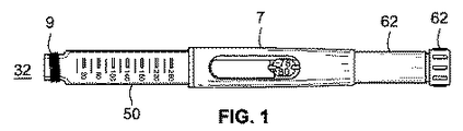
本発明は、薬用モジュール用のロック機構、及び薬用モジュール用の二次パッケージングを供する。薬用モジュールは、二次薬物化合物(薬剤)の固定された所定の用量、及び一次、つまり第一の薬物化合物の可変用量を、単一出力つまり薬物投薬インターフェースを通して投与する。使用者による第一の薬剤の用量設定によって、第二の薬剤の固定用量が自動的に定められ、それは、好ましくは、一体型フローディストリビュータを有するカプセル又はリザーバ中に含有される単一用量である。好ましい実施態様において、薬物投薬インターフェースは針カニューレ(中空針)である。図1は、薬用モジュール4(図2又は7を参照)が取り付け可能な薬物送達デバイス7の一例を図示する。薬用モジュールはカートリッジホルダ50の遠位端32上の連結手段9によって取り付けできる。各薬用モジュールは、好ましくは内蔵型で、そして、デバイス7の遠位端32で取り付け手段9に適合可能な取り付け手段8を有する、シールされかつ殺菌された使い捨てのモジュールとして供される。
The present invention provides a locking mechanism for a medicated module and a secondary packaging for the medicated module. The medicated module administers a fixed predetermined dose of the secondary drug compound (drug) and a variable dose of the primary, or first drug compound, through a single output or drug dosing interface. Setting a dose of the first drug by the user automatically determines a fixed dose of the second drug, which is preferably a single dose contained in a capsule or reservoir with an integrated flow distributor . In a preferred embodiment, the drug dispensing interface is a needle cannula (hollow needle). FIG. 1 illustrates an example of a
薬用モジュールを選択された薬物送達デバイスに取り付けるために、ねじ、スナップロック、スナップ嵌め込み、ルアーロック、バヨネット、スナップリング、キースロット及びそのような連結の組合せのような恒久的及び取り外し可能な連結手段の全てのタイプを含む如何なる公知の取り付け手段8も使用され得る。図2、4、及び7は、薬用モジュール4のハブ51上の対応する雌バヨネット型連結8に特定的に鍵がかけられる独特のバヨネット型連結としての取り付け手段9を図示する。図2、4、5、及び7において示された実施態様は、カプセル31内に、そして具体的にはリザーバ22中に完全に含有される単一用量としての第二の薬剤の便益を有し、従って第二の薬剤と薬用モジュール4の構築に使用される材料、特に、薬用モジュールの構築において使用されるハウジング10、バイパスハウジング52又は如何なる他の部材の間の材料の不適合性のリスクを最小化する。
Permanent and removable coupling means such as screws, snap locks, snap fits, luer locks, bayonets, snap rings, key slots and combinations of such couplings for attaching medicated modules to selected drug delivery devices Any known attachment means 8 including all types of can be used. 2, 4 and 7 illustrate the attachment means 9 as a unique bayonet-type connection that is specifically locked to the corresponding female bayonet-type connection 8 on the
投薬操作の最後にカプセル31中に残り得るであろう、再循環及び/又は滞留領域によって引き起こされる、第二の薬剤の残留容積を最小化するために、リザーバ22の統合部分としてフローディストリビュータ23を有することが好ましい(図5を参照)。二次薬剤の単一用量を含有するリザーバ22はセプタム6a及び6bを用いてシールできて、それはキーパ又はプラグ20a及び20bを用いてカプセルに固定される。好ましくは、キーパは針3及び5並びにバイパス46と流体連通状態にある流体チャンネルを有し、それは、好ましくは、バイパスハウジング52の内面の部分である。これと一緒に、流体経路によって、注射前の薬物送達デバイスのプライミングが可能になる。好ましくは、リザーバ、フローディストリビュータ、キーパ及びバイパスは、一次薬剤と適合する材料で作られ得る。適合する構築材料の例としては、限定するものではないが、COC(エチレン及びノルボルネンに基づく非晶性ポリマ、環状オレフィン共重合体とも称される、エチレン共重合体、環状オレフィンポリマ、又はエチレン−ノルボルネン共重合体);LCP(アミド基によってリンクされた、線形に置換された芳香族環を含有する、そしてp−ヒドロキシ安息香酸及び関連単量体に基づく、部分的に結晶性の芳香族ポリエステルを更に含有し得るアラミド化学構造を有する液晶ポリマ、そしてまた高度に芳香族のポリエステル);PBT(ポリブチレンテレフタレート熱可塑性結晶性ポリマつまりポリエステル);COP(ノルボルネン又はノルボルネン誘導体の開環重合に基づく環状オレフィンポリマ);HDPE(高密度ポリエチレン);及びSMMA(メチルメタクリレート及びスチレンに基づくスチレンメチルメタクリレート共重合体)が挙げられる。カプセル及び第一の薬剤カートリッジの両者と共に使用される針突刺し可能なセプタム、栓及び/又はシールは、TPE(熱可塑性エラストマー);LSR(液状シリコンゴム);LDPE(低密度ポリエチレン);及び/又は天然又は合成の医療グレードのゴムの如何なる種類のものも用いて製造され得る。
In order to minimize the residual volume of the second drug caused by the recirculation and / or residence area that could remain in the
フローディストリビュータ23の設計は、第二の薬剤の少なくとも約80パーセントが針3の遠位端を通してリザーバ22から排出されることを保証しなければならない。最も好ましくは、少なくとも約90パーセントが排出されるべきである。理想的には、カートリッジホルダ50内に含有される(示されていない)一次リザーバ中の第一の薬剤の変位によって、そしてカプセル31を通して、リザーバ22中に保存された第二の薬剤の単一用量が二つの薬剤の実質的な混合なしで変位されるであろう。
The design of the
薬用モジュール4の複数回使用デバイス7への取り付けによって、近位針5が、複数回使用デバイス7のカートリッジホルダ50中に位置する一次薬剤のカートリッジの遠位端をシールしている(示されていない)セプタムを突き刺すことになる。一旦、針5がカートリッジのセプタムを通過したら、第一の薬剤と針5の間に流体連結がなされる。この点で、システムは用量ダイヤルスリーブ62を用いて、少ない数の単位をダイヤルして出すこと(又は、単一用量選択のみが可能な場合、デバイスをぴんと立てる(coking)こと)によってプライミングできる。一旦、デバイス7がプライミングされると、次いで、ニードルガード42の起動によって、デバイス7上での用量ボタン13の起動を介して、薬剤の皮下注射によって薬剤の投薬が可能になる。我々の発明の用量ボタンは、用量ダイヤルスリーブ62によって設定された第一の薬剤の用量をデバイスの遠位端32に向かって動かすことになる如何なるトリガー機構でもあり得る。好ましい実施態様において、用量ボタンは、第一の薬剤の一次リザーバ中にピストンを係合させるスピンドルに操作可能に連結される。更なる実施態様において、スピンドルは、二つの明確なねじを含んでなる回転可能なピストンロッドである。
The attachment of the medicated module 4 to the
薬用モジュール4の一つの実施態様が図2及び7において図示される。これらの実施態様において、薬用モジュール4はリザーバ22、二つのキーパ20a及び20b並びに二つのシール6a及び6bを含んでなるカプセル31を含有する。リザーバ22は二次薬剤の固定された単一用量を含有する。幾つかの場合において、この第二の薬剤は、薬物送達デバイス7中の一次薬物化合物と同じか又はそれとは異なり得る二つ又はそれより以上の薬物作用物質の混合物であり得る。好ましくは、カプセルは薬用モジュール内に恒久的に固定されるが、幾つかの場合において、空になったとき、カプセルが取り外され、そして新しいカプセルと交換され得るようにモジュールを設計することが好ましくあり得る。
One embodiment of the medicated module 4 is illustrated in FIGS. In these embodiments, the medicated module 4 contains a
図5及び7において示される実施態様において、カプセル31は、第二の薬剤に対して密封シールされそして殺菌されたリザーバ22を供する突刺し可能な膜つまりセプタム6a及び6bを用いてシールされる端部を有する。一次つまり近位の係合針5は、注射中にニードルガードが近位方向に動いているとき、モジュールのハウジング10の近位端に連結されたそしてカプセル31を係合するように構成されたハブ51中に固定され得る。出口、つまり、遠位針3は、好ましくは、下方ハブ53中に取り付けられ、そして初期により下方のキーパ20b内に突き出る。針3の近位端は、注射中に、ニードルガード42及びばね48によってかけられる力によってバイパスハウジング52が回転しそして近位に動かされるとき、より下方のセプタム6bを突刺す。
In the embodiment shown in FIGS. 5 and 7, the
送達デバイスに最初取り付けられるとき、薬用モジュール4は使用前位置つまり始動位置に設定される。好ましくは、インジケータ41は窓54を通して見えて、薬用モジュールの使用前状態を使用者に知らせる。インジケータは、好ましくは、外部本体中の開口部を通して見ることができるガード42の近位端の外面上の色付きストリップ又は帯である(図3を参照)。ニードルガード42は、アーム2とチャンネル1の係合によって外部ハウジング10の内面と摺動可能に係合される。保持スナップ56はガードがその完全に伸ばされた位置で外部ハウジングを係合解除することを防ぐ。ハウジング10はカプセル31を含有するバイパスハウジング52を保持する内部空洞21を部分的に画成する。ハウジング10の近位端の部分は、針5を保持する上方ハブ51を画成する。場合により、図7において図示された通り、ショルダキャップ25は外部ハウジング10の近位外面に追加され得る。このショルダキャップは、モジュール中に含有される薬剤のタイプ/強度を使用者に同定させるための表示部として役立つように構成され得る。表示部は触覚、文字、色、味又は臭いであり得る。
When initially attached to the delivery device, the medicated module 4 is set to a pre-use or start position. Preferably, the
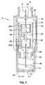
図7は、針3及び5がセプタム6a及び6bを突刺していない使用前つまり始動状態に設定された薬用モジュールの切取図つまり断面図を示す。この位置において、バイパスハウジング52はその最も伸ばされた位置にあり、そして針3及び5はカプセル31中に含有された薬剤と流体連通状態にない。カプセルはバイパスハウジング52によって支持される。カプセル31のこの中立的な又は吊られた状態において、一次薬剤は、デバイス7のカートリッジホルダ50中のカートリッジから針5を通してキーパ20a内に、そしてバイパス46を通してキーパ20b内に、そして最終的には針3を通して外に流れ得る。このフロー構成によって、使用者が薬物送達デバイス7上の用量ダイヤルスリーブ62及び用量ボタン13を用いて一次薬剤の小さい用量を投与することによってプライミング工程又は手順を実行することが可能になる。
FIG. 7 shows a cut-out or cross-sectional view of the medicated module set in a pre-use or start-up state where the
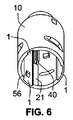
圧縮ばね48は、図7において図示された通り、ガード42を伸ばされた(保護された)位置へと付勢するために、バイパスハウジング52の遠位端とガード42の内部近位面の間に位置する。組立の際、ばね48は、下方ハブ53に抗して付勢力を近位に向けて供するためにわざと圧縮される。ばね48のこの事前圧縮が可能であるのは、下方スタンドオフポケット65と係合する下方ハブ53の上方スタンドオフポケット66及び脚17と係合する外部ハウジング(図6)の内面上に位置する、半径方向のスタンドオフ40によって、下方ハブ53及びバイパスハウジング52が軸方向に近位方向に動くことを防がれるためである。これらのスタンドオフ/脚及びポケットの組合せによって、前述の通りデバイスがトリガーされるまで、下方ハブ及び上方ハブの針が、カプセルの中心内に突刺すことが防がれる。
A
ガード42の近位内面は、バイパスハウジング52の外面に形成された一つ又はそれ以上の軌道13又は案内路中を走行する、一つ又はそれ以上の内側に向って突きでる機能、駆動歯、ピップ(pip)又は同様の構造12を有する。図3において示された通り、軌道13は、薬用モジュール4の単一使用の後、駆動歯12が更なる軸方向運動を阻止され、そしてガード(及びデバイス)が、針の遠位端がガード42によって完全にそして安全に覆われる、保護された位置に「ロックされる」ように、特定の幾何形状を有する四つの経路、19、14、15及び16として述べられ得る。
The proximal inner surface of the
我々の薬用モジュールアセンブリの一つの独特な特長は、アセンブリが使用されるときに与えられる使用者へのフィードバックである。特に、アセンブリは、注射部位からのガードの注射/除去の完了の際、ニードルガードが安全にロックアウトするであろうように、それらが一番目にデバイスをトリガーされたこと、そして二番目に「コミット」点に達したことを使用者に示すように、可聴の及び/又は触覚「クリック」を発することができるであろう。この可聴の及び/又は触覚機能は次のように働き得るであろう。述べられた通り、ニードルガード42は外部ハウジング10によって回転制約され、そしてバイパスハウジング52上の軌道13の経路19中に初期に存在する一つ又はそれ以上の駆動歯12を有する。ガードが近位に動かされるとき、ばね48は更に圧縮されて、下方ハブ53上で近位方向に追加の力をかけ、それは脚17と係合される下方スタンドオフポケット65によって初期に軸方向に制約される。同様に、バイパスハウジング52は、外部ハウジング10の内面上のスタンドオフ40と係合する上方スタンドオフポケット停止部132によって近位で動くことを制約される。駆動歯12は経路19中を走行し、バイパスハウジングを少しばかり回転させる。この回転によって上方スタンドオフ40は上方スタンドオフポケット停止部132から係合解除するであろうし、駆動歯が経路14に入ることが可能になり、そして脚17が下方スタンドオフポケットからブロック解除され、バイパスハウジングが近位に動くことが可能になって、それと共にカプセル31が運ばれ、ここでそれは次いで、針3及び5を係合し得る。ガードが近位方向に動き続けるので、駆動歯は経路14から転移点14aを通り経路15内に動き、バイパスハウジングの更なる回転を引き起こす。この回転が完了するとき、駆動歯は経路13に移り、可聴の「クリック」音、同様に触覚を使用者に潜在的に発する。この転移通過点15a(及び軌道上のそのすぐ下の対応する点)を通る移動は「コミット」点を構成し、そしてそのように、注射部位からデバイスが除去される際にそれが伸びるとき、一旦それはニードルガード42に到達すると「ロックアウト」するであろう。
One unique feature of our medicated module assembly is the user feedback given when the assembly is used. In particular, the assembly was first triggered on the device so that the needle guard would safely lock out upon completion of injection / removal of the guard from the injection site, and secondly “ An audible and / or tactile “click” could be issued to indicate to the user that the “commit” point has been reached. This audible and / or tactile function could work as follows. As stated, the
述べられた通り、ガード42の遠位端は、追加の安全手段を供し、そして我々のニードルアセンブリを用いた注射中に、ガードによって注射部位上にかけられた圧力を減じる平坦面33を有する。平坦面33は実質的に針3へのアクセスを覆うため、使用者は、アセンブリがロックされた位置に置かれた後、針の遠位先端へのアクセスを得ることを防がれる。好ましくは、平坦面における針パススルー穴21の直径Dは針カニューレ3の外径のそれの10倍よりも決して大きくない。
As stated, the distal end of the
ニードルガード42の外部近位面は、好ましくは、少なくとも二つの異なる色付きストリップ又は帯であるインジケータ41を好ましくは有し、その各々は外部ハウジング10中の開口部又は窓54を通して連続して見ることができる。一方の色はモジュールの使用前又はプライミングされた状態にあることを表し得るであろうし、そして他方の色はモジュールが完了した又はロックされた状態を表し得るであろうし、そして別の色は、使用者がトリガー点より後だが「コミット」点より前で、注射を停止する場合の、トリガー又は「コミット」点を通した転移を示すために使用され得るであろう。例えば、緑色は使用前位置であり得て、そして赤色の帯びはモジュールが使用されそしてロックされていることを示すために使用され得るであろうし、そして橙色はデバイスがトリガーされたがロックアウトされていないことを示し得るであろう。または、この視的情報/フィードバックを供するために、グラフィック、記号、又は文字が色の代わりに使用され得るであろう。または、これらの色はバイパス空洞の回転を用いて表示され得て、そしてバイパスハウジング上にプリントされ得るか又はその内に埋め込まれるであろう。それらは、ニードルガードが透明材料で作られることを保証することによって、開口部を通して見ることができるであろう。
The outer proximal surface of the
図8は、方向矢印39によって図示される通りの、一つ又はそれ以上の軌道13における駆動歯12の走行を図示する。駆動歯12は位置Aで始まり、そして、それが転移点14aを通過して動き、そして位置Bに到達するまで、ニードルガードの軸方向運動を通してバイパスハウジングを回転付勢する。一旦、駆動歯が位置Bに達すると、バイパスハウジング及び下方ニードルハブは近位に動き、カプセル31が係合針3及び5を係合することになり、そして駆動歯は位置Cに対して動き(これはデバイスのトリガーと称される)そしてニードルガードの駆動歯が位置Cである効果的な位置をもたらすのは、保存されたエネルギの放出下で近位に動くバイパスハウジング/下方ハブである。ニードルガードが、保存されたエネルギの放出の動作下では動かないこと、そしてトリガーの点で、ニードルガードから離れて相対的に動くのは針ハブ及びバイパスハウジングだけであること、従って駆動歯は位置Bから位置Cに動くことを述べるのは重要である。ニードルガードが後退し続けるので、駆動歯12は位置Dに経路14中を近位で動き、ここでそれは歯12が経路16内へと転移点15a(コミット点)を通過するまで、バイパスハウジング52上に回転的付勢をかけ、それを再び回転させることになる。次いで駆動歯は、位置Eに達するまで近位で動く。この点で、ニードルガード42は完全に後退されそして針の完全に利用可能な挿入可能長さが露出される。一旦、使用者がガードを皮膚との接触から除去すると、ガードは、ガードの内部近位面上にばね48によってかけられる遠位付勢力の結果として伸び始める。トリガー/突刺しばね並びに、一旦、トリガー後に伸ばされたら、ニードルガードのばねの両方として動作するために、保存されたエネルギばねを利用することはこの設計の独特な態様である。それは、それが両方の役割を果たすことができるような場所にばねを置くことによって、これらの別々の機能に対して二つの別々のばねを使用する必要性を無効にする。初期に、例えば、薬用モジュールの組立又は製造中に、付勢部材は圧縮されて、トリガーのための準備として、下方ハブ/バイパスハウジング上に力をかける。一旦、トリガーされると、それは近位に伸び、その際、ニードルガードがそれに抗して後退するとき、それは次いで遠位端から圧縮され得る。この第二の圧縮によってニードルガードを、それが注射部位から外されるとき、伸ばされたそしてロックされた位置へと押し戻す力が供される。ガードがその完全に伸ばされた使用後の位置へと、好ましくは、始動位置よりも少なく伸ばされて動くので、駆動歯12は、それが転移点16aに達するまで経路15中を遠位に動き、ここでそれは次いで、歯12が経路16に入りそして位置Fに達するまで更に再び回転するためにバイパスハウジング52を回転付勢する。バイパスハウジング52のこの最後の回転によってロックアウトボス70がロックアウト機能71を係合することになる。これによって、バイパスハウジングの如何なる更なる回転又は軸方向運動も防がれる。ニードルガードは、前に定義された通り、駆動歯と軸停止部16bの係合によって、更なる実質的な軸方向運動を防がれる。上述の要求される機能を果たすために多数の歯配置及び/又はプロファイル、例えば、簡単な同じ歯プロファイル又はより複雑な複数の角のあるプロファイル、が使用され得るであろうことは、我々の発明の範囲内である。特別なプロファイルは、バイパスハウジングの要求されるコミット点及び回転に依存する。外部ハウジングに対するバイパスハウジングとしての、バイパスハウジングに対する下方ニードルハブの類似の軸方向/回転方向のロックが、針のトリガー後及びロックアウト後の動きを防ぐために統合され得るであろうことも、我々の発明の範囲内である。
FIG. 8 illustrates the travel of the
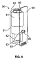
図9は、トリガーロックされた位置における二次パッケージング90内の、図2及び7において図示された薬用モジュール4のような例示的モジュール80の斜視図である。
FIG. 9 is a perspective view of an
この実施態様において、モジュール80は、図2及び7の薬用モジュール4に対して述べられたものと同じ部材の少なくとも幾つかを含み得る。モジュール80はデバイス81、ニードルガード82、及びくぼみ又は穴83を含む。穴83は、好ましくは、デバイス81及びニードルガード82の両者を通して伸びる。
In this embodiment, the
二次パッケージング90は、内面92を有する本体91、外面93、及び蓋94を含む。一つの実施態様において、ペグ95は蓋94の内面92から伸びるが、ペグは、パッケージングからの、デバイスの容易な取り外しを可能にするパッケージング内のどこにでも取り付けられ得るであろう。
モジュール80がパッケージング90内に置かれた後、蓋94は閉じられ、そしてパッケージング90のペグ95はモジュールの穴83内に入る。図9は穴83内に完全に挿入されたペグ95を示す。ペグ95が穴83内にある一方、ペグ95はデバイス81及びニードルガード82の両方を通して伸びて、デバイス81に対するニードルガード82の軸方向運動を阻止し、そして防ぐ。これによって、ペグ95が、ロックされた、トリガー不可能な位置に薬用モジュール80を維持することが可能になる。
After the
図10は、図9の二次パッケージング内のモジュールの側面図である。この図において、蓋94はモジュール80から離れて開けられる。蓋94が引っ張って開けられるとき、ペグ95は穴83から出て、ニードルガード82がデバイス81に対して軸方向に動くことを防いでいたブロックを取り除く。このようにして、ニードルガード82はここで動くことが可能であり、そしてモジュール80はトリガー可能な位置にある。
10 is a side view of the module in the secondary packaging of FIG. In this figure, the
図9〜10において図示されたシステムは、ペグ95がモジュール80内に挿入されるときは何時でも、モジュールがもう一度トリガーロックされた位置にあるように再使用可能であり得る。
The system illustrated in FIGS. 9-10 may be reusable so that whenever the
図11は、図2及び7において図示された薬用モジュール4のような、トリガーロックされた位置にある例示的モジュール100の斜視図である。
FIG. 11 is a perspective view of an
この実施態様において、モジュール100は、図2及び7の薬用モジュール4に対して述べられたものと同じ部材の少なくとも幾つかを含み得る。モジュール100はデバイス101、ニードルガード102、及び一対のスリット103を含む。スリット103は、好ましくは、デバイス101及びニードルガード102の両者を通して伸びる。
In this embodiment, the
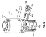
グレナダピンのようなピン104は、例えば、図11において示された通り、スリット103内に挿入される。ピン104は、好ましくは、グリップ部分105及び一対の伸長部106を含む(図12において示される)。伸長部106がモジュール100内に挿入されるように、ピン104がスリット103内に完全に挿入されるとき、その伸長部はニードルガード102がデバイス101に対して軸方向に動くことを阻止する。これはトリガーロックされた位置である。
A
ピン104が矢印107によって示された方向に引かれる際に、伸長部106はスリット103から除かれる。一旦、伸長部106がモジュール100から完全に除かれると、ニードルガード102はデバイス101に対して動くことができる。このように、図12はトリガー可能な位置におけるモジュールを示す。
The
図11〜12において図示されたシステムは、ピン105がモジュール100内に挿入されるときは何時でも、モジュールがもう一度トリガーロックされた位置にあるように再使用可能であり得る。
The system illustrated in FIGS. 11-12 may be reusable so that whenever the
図13は、二次パッケージング115内の例示的モジュール110の側面図である。図13において見られ得る通り、二次パッケージング115は外部モジュール100機能に実質的に一致するように輪郭をとられ、ニードルガード112及びデバイス111が互いに対して動くことを防ぐ。これはトリガーロックされた位置である。
FIG. 13 is a side view of the
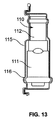
二次パッケージング115は、(図14において示された通り)開かれたときに、モジュール110が除かれることを可能にする蓋116を含む。一旦、モジュール110が二次パッケージング115から除かれると、それはトリガーされ得て、そしてニードルガード112及びデバイス111は互いに対して動くことができる。
The
図13〜14において図示されたシステムは、モジュール110が閉じられた二次パッケージング115内にあるときは何時でも、モジュールがもう一度トリガーロックされた位置にあるように再使用可能であり得る。
The system illustrated in FIGS. 13-14 can be reusable so that whenever the
図15は例示的モジュール120の斜視図である。モジュール120はデバイス121、ニードルガード122、及び二次ガード123を含む。二次ガード123は、第一の端部124及び、二次ガードがガードの遠位外面に抗して軸方向に押されるような時間まで、デバイス本体に対するニードルガードの軸方向の走行を防ぐ一対の伸長部126を含み、それによって、デバイスは「トリガー可能な」状態にあり、各伸長部は、図16の断面において示される通り、フック形状の第二の端部127を有する。伸長部は、好ましくは、第一の端部124から実質的に直交して伸びる。第一の端部124は、針が通過することを可能にするために、部材の中央に穴を有する円筒部材であるよう形付けられ得る。
FIG. 15 is a perspective view of an
それがトリガー可能な位置にあるようにモジュールを起動するために、第一の端部124は使用者の皮膚に抗して押される。二次ガード123は二次パッケージング中の機能によって外側に向かって保持され、そのようにして、デバイスがパッケージングから除かれるまで、それが軸方向に動くことができないよう保証する。皮膚などの注射部位に抗してモジュールを押すことによって、伸長部が起動され、それによってニードルガードを解除する。
In order to activate the module so that it is in a triggerable position, the
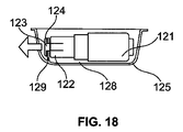
この代替構成において、図17は図15の薬用モジュール120を図示し、ここで、モジュール120は二次パッケージング125とインターフェースで連結する。二次パッケージング125は内面128を有する本体を含む。フランジ129は内面128から本質的に直交して伸びる。モジュール120が二次パッケージング125内に位置するとき、フランジ129は第一の端部124とニードルガード122の端部の間に位置する。このように、フランジ129は二次ガード123の第一の端部124がニードルガード122に向かって戻るように動くことを防ぎ、そのようにして薬用モジュールがトリガーロックされた位置にあるよう維持する。この配置において、第一の端部124は内側に向かって跳ねるよう付勢され、そしてフランジ129は端部が内側に向かって跳ねることを防ぐ。従って、デバイスがパッケージングから除かれ、そして端部124がフランジ129から係合解除するとき、端部124は内側に向かって自動的に跳ね、そしてデバイスをトリガー可能にする。このように、デバイスは二次パッケージング中に安全に維持され、そしてそれをこのパッケージングから除く動作を通して自動的に「備えのある(armed)」状態に留める。
In this alternative configuration, FIG. 17 illustrates the medicated
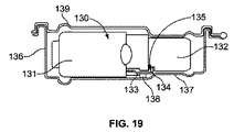
図19は、図2及び7において図示された薬用モジュール4のような、二次パッケージング136内の例示的モジュール130の側面図である。モジュール130はデバイス131、ニードルガード132、及びばねラッチ133を含む。ばねラッチはデバイス131に取り付けられ得て、そしてニードルガード132中のくぼみ135内に嵌入するフック部材134を含み得る。
FIG. 19 is a side view of an
図19において、モジュール130は二次パッケージング136内のトリガーロックされた位置にある。二次パッケージング136は内面137、内面137から伸びている伸長部138、及び蓋139を含む。この位置において、二次パッケージングの内部からの伸長部138はばねラッチ133を押し付け、ばねラッチ133を圧縮する。圧縮された状態において、ばねラッチ133のフック部材134はニードルガード132のくぼみ135内に嵌入する。ばねラッチ133がくぼみ135中にあるとき、ニードルガード132はデバイス130に対して動くことができない。ばねラッチ133はニードルガード133をトリガーロックされた位置に維持する。
In FIG. 19,
図20は、トリガー可能な位置における図19のモジュール130の側面図である。蓋139が開かれ、そしてモジュール130がパッケージング136から除かれるとき、ばねラッチ133はもはや圧縮されず、そして伸長部138によってくぼみ135内のしかるべき位置に留められる。ばねラッチ133はその緩和された位置内に動き、ラッチ133はくぼみ135から動き出す。モジュール130はここでトリガー可能な位置にあり、そしてニードルガード132は伸長部131に対して動くことができる。
20 is a side view of
図21は、図2及び7において図示された薬用モジュール4などの、二次パッケージング145内の例示的モジュール140の断面図である。モジュール140はデバイス141、ニードルガード142、及び双安定ばね143を含む。二次パッケージング145は内面147を有する円筒状本体146、及び内面147に沿った栓又は伸長部148を含む。伸長部148はパッケージング145の内面147に対して凸である。飛び出したとき、ばね143は、図21において見られ得る通り、本体146中の開口部149を通過する。ニードルガード142が軸方向の負荷を受ける場合、ばね143は、バネエレメント143内に噛む(図21における小さな三角形として現れる)開口部の端部とぶつかるであろう。ばね143が戻されるとき、それは本体開口部149から十分に離れ、そして、ニードルガード142が軸方向に動かされるとき、妨害しない。
FIG. 21 is a cross-sectional view of an
モジュール140が図21において示されたトリガーロックされた位置にあるとき、双安定ばね143はモジュール140から離れて外側に向かって押される。この位置において、ばね143はデバイス141をトリガーするであろうニードルガード142の相対的動きを防ぐ。
When the
モジュール140及び二次パッケージング145の断面図である図22において、モジュール140はパッケージング145から部分的に引き出される。モジュール140がパッケージング145から引き出される際に、双安定ばね143は隆起148に亘って動く。圧力隆起148はばね143上に作用してばね143をゆがませ、ばね143を反転させることになり、そしてばね143はここで図22において示された反転された位置において安定になる。ばね143がもはや、デバイス141にかんして動くニードルガード142の邪魔にならないので、モジュール140はここでトリガー可能な位置にある。
In FIG. 22, which is a cross-sectional view of
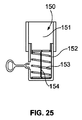
図23〜25は、図2及び7において図示された薬用モジュール4のような例示的モジュール150の断面図である。モジュール150はデバイス151、ニードルガード152、圧縮バネ153、及び拘束体154を含む。ニードルガード152は開口部155を含む。モジュール150がトリガーロックされた位置にあるとき、図23において示された通り、ハンドル157及びクレンチング部材158を有するピン156は開口部155中に存在する。拘束体154は、ばね153の少なくとも一部を横切って軸方向に伸びるワイヤーであり得る。
23-25 are cross-sectional views of an
図23において、ハンドル157はモジュール150の外部にあり、一方、クレンチング部材はモジュール150の内部上にある。図23において示された通り、ピン156のクレンチング部材158は拘束体154の二つ折りされた又は折り畳まれた部分を保持する。拘束体154の二つ折りされた部分は、長さがより短い拘束体154をもたらし、それによってばね153は圧縮された状態に保持される。圧縮された状態にあるばね153は偶発的なトリガーを防ぐことを助ける。
In FIG. 23, the
図24及び25はピン156の除去プロセスを図示する。最初に、図24において示された通り、ハンドル157がモジュール150から引き離される際に、ピンのクレンチング部材158は拘束体154上のそのグリップを放出する。拘束体154の二つ折りされた部分は真直ぐ伸び始める。
24 and 25 illustrate the process of removing the
図25において、ピン156はモジュール150から除かれ、そして拘束体154は真直ぐである。拘束体154が二つ折りされた部分を持たずに真直ぐであるとき、拘束体154は増加した長さを有し、そしてばね153は、より短い長さの拘束部材によってそれがもはや圧縮状態に保持されない故に、自由に動く。図25は、このように、ばねの動きによってニードルガード152がデバイス151に対して動くことが可能であるので、トリガー可能な位置を示す。
In FIG. 25, the
図26〜28は、図23〜25の拘束体を有するモジュールの例示的代替実施態様を図示する。図26はパッケージング165内の複数のモジュール160を図示する。モジュールはデバイス161及びニードルガード162を含む。パッケージング165は電源165、複数のポート166、及び複数の電線167を含む。薬用モジュール160はポート166の各々の内に挿入される。各電線167の第一の端部は電源165に取り付けられ、そして各電線167の第二の端部はポート166の一つの中に存在する薬用モジュールに取り付けられる。好ましくは、二つの電線167は各モジュールに取り付けられる。電線167の第二の端部の各々はニードルガード162の底面に取り付けられる。
26-28 illustrate an exemplary alternative embodiment of a module having the restraint of FIGS. 23-25. FIG. 26 illustrates a plurality of
図27において示された通り、ニードルガード162内に圧縮ばね163、一対のヒューズ線164及び一対の電流送信器169がある。各ヒューズ線164は一方の端部で電流送信器169に取り付けられ、そして他方の端部でばね163の一部に取り付けられる。ヒューズ線164は圧縮された状態でばね163を保持して、ばね163がかなりの距離を動くことを許さない。ヒューズ線164はこのように、図23〜25を参照して論じられた拘束体154に類似して、ばね163を横切って軸方向に達するように位置する。各ヒューズ線164はばね163が動くことを完全に防ぎ得る。図28は薬用モジュールを図示し、そしてニードルガード162の底面上の電流送信器169を示す。
As shown in FIG. 27, there is a
電源165においてパワーが生み出され、そしてそのパワーは電流送信器169を介してニードルガード162内のヒューズ線164に電線167を通して電流として伝えられる。ヒューズ線164は融解するのに十分な電流を受け取る。ヒューズ線164が融解するとき、それらはもはや圧縮ばね163を抑止しなくなり、そしてばね163は自由に緩和して薬用モジュール160内のハブのようなエレメントが動くことを可能にする。
Power is generated at
ヒューズ線164は、安定でかつ予測可能な特性を供給するために、亜鉛、銅、銀、アルミニウム又は合金で作られ得る。ヒューズは、理想的には、その定格電流を無期限に運び、そして少しの過剰電流で迅速に融解するであろう。または、デバイスがパッケージングから除かれるとき、例えば、除くために回転されるとき、接触がなされ得て(そして回路が完了され得る)。そのような構成の一つの利点は、それが電気排出(electrical drain)を低減することを助けるであろうことである。
The
図29〜31は、図2及び7において図示されたモジュール4のようなモジュール170及び二次パッケージング175を図示する。図30において示された通り、モジュール170はデバイス171及びニードルガード172を含む。デバイス171の近位端に穴173がある。デバイス171は、その遠位端で複数のスロット174も含む。
FIGS. 29-31 illustrate a
図30において示された通り、二次パッケージング175は、パッケージング175の内面から伸びる複数のペグ176、蓋177、及び蓋177を含む。蓋177は取り外し可能であり、そしてその周囲に沿って弱くされた領域を含み得る。蓋177は二次パッケージング175の部分として成形され得る。
As shown in FIG. 30, the
図29は二次パッケージング175内のモジュール170の部分断面図である。一次デバイス179は挿入されて蓋177を破いており、穴178を生み出し、そしてデバイス穴173内に動く。第一のデバイス179は、デバイス171内の対応する溝内にねじ込むねじのような取り付け手段を含み得る。第一のデバイスは、例えば、図1において図示された薬物送達デバイスのような薬物送達デバイスであり得る。
FIG. 29 is a partial cross-sectional view of the
図30は二次パッケージング175内のモジュール170の斜視図である。図30において示された通り、一次デバイス179はモジュール170に張り付けられる。ペグ176はスロット174内に挿入され、デバイス171に対するニードルガード172の動きを制約する。
FIG. 30 is a perspective view of the
図31は、二次パッケージング175から引き出されたモジュール170の斜視図である。モジュール170は、一旦、それが取り付け手段を介して薬用モジュール170に連結されると、一次デバイス179を引くことによって、好ましくは、除かれる。蓋177は、一次デバイスが二次パッケージング175から引かれるので、薬用モジュール170及び一次デバイス179に取り付けられた状態に留まる。スロット174は、モジュール170が二次パッケージングから引き出されるとき、それがペグ176から引き出され得るように構成される。これによって、ニードルガード及び本体の相対的な動きが可能になり、そのようにしてトリガー可能状態に導かれる。
FIG. 31 is a perspective view of the
図32は、二次パッケージング185内の、図2及び7において図示された薬用モジュール4のようなモジュール180の部分断面図である。薬用モジュール180はデバイス181、ニードルガード182、及びクリップリング183を含む。
32 is a partial cross-sectional view of a
図34において示された通り、クリップリング183は、リングの外周に沿って複数のカットアウト184、及びリング183の内周に沿って複数のラグ186を含む。
As shown in FIG. 34, the
図33は、図32のニードルガード182を示す。図33において示された通り、溝187はニードルガード182の外面周囲の少なくとも部分に沿って存在する。
FIG. 33 shows the
取り付けリング183をニードルガード182に取り付けるために、ラグ186は溝187と係合する。リング183は、製造プロセス中に、ニードルガード182上に組立てられ得る。リング183の外周又は周辺上の複数のカットアウト184は二次パッケージング185内にカチッと閉まる。一つの配置において、これは不可逆的連結である。つまり、一旦、リング183が二次パッケージング185内にカチッと閉められると、それは取り外すことができない。従って、唯一の可能な動作は二次パッケージング185をリング183から取り外すことであり、ここで、ラグ186を溝187から取り外すために要求される力は、カットアウト184を二次パッケージング中のノッチから取り外すために要求される力よりも弱い。
In order to attach the
モジュール180は二次パッケージング185内にある一方で、ニードルガード182の周辺を超えて伸びるリング183はデバイス本体181に抗して詰め込まれ、デバイス本体181に対するニードルガード182のかなりの動きを防ぐ。これはトリガーロックされた位置である。
While the
使用者がモジュール180を、使用前に二次パッケージング185から取り除くとき、リング183はパッケージング185に取り付けられた状態に留まる。リング183が取り除かれると、ニードルガード182がデバイス181に対して動くことができるため、モジュール180は生かされそしてトリガー可能な位置にある。
When the user removes
図35は、図2及び7において図示された薬用モジュール4のようなモジュール190の斜視図である。モジュール190はデバイス本体191、ニードルガード192、及び引き裂き又は剥離ストリップ193を含む。剥離ストリップ193はデバイス本体191に適用され、そしてデバイス本体191に対するニードルガード192の動きを防ぐ機能を含む。例えば、ストリップ193の内面はペグ、ピン、スライダーエレメントなどを含み得るであろう。これらの機能は、二つの部材が互いに対して動くことを防ぐために、そしてそれによって、偶発的なトリガーを防ぐために、デバイス本体191及びニードルガード192の両者内の対応するオリフィス内に嵌入し得るであろう。
FIG. 35 is a perspective view of a
使用者は、矢印194を用いて示された方向にストリップ193を剥離する。代替実施態様において、使用者は、もし、シュリンク包装された又は半剛直な開封明示ストリップが使用される場合、ストリップ193を引き裂き得る。ストリップ193を除去することによって、ブロック機能が除かれそしてモジュールが起動されることが可能になる。
The user peels the
図36は、二次パッケージング205内の、図2及び7において図示された薬用モジュール4のようなモジュール200の断面図である。モジュール200はデバイス本体201及びニードルガード202を含む。デバイス本体201はデバイスの外周に沿ってねじ203を含む。ニードルガード202はデバイスの外周に沿ってねじ204を含む。デバイス本体ネジ203はニードルガードねじ山204とは異なるピッチを有し得る。ピッチにおけるこの違いは、事前負荷部材を張力状態にするよう作用し得る。例えば、或る部分を他の部分よりも少し速く二次パッケージング内に捲き取ることによって、二つの部材は効果的に「吊りあげられて(jacked)」分離され、そして互いから引き離される。これは、それらが同じ部材、二次パッケージング、と係合される故に成され得る。もし、ピッチにおける違いが大き過ぎると、デバイスがパッケージング内に完全に捲かれ得る前に、ねじは動かなくなる(lock up)であろう。
FIG. 36 is a cross-sectional view of a
二次パッケージングは、デバイスねじ山203に対応する第一のねじ溝206、及びニードルガードねじ山204に対応する第二のねじ溝207を含む。
The secondary packaging includes a
モジュール200が二次パッケージング205内に位置するとき、溝はそれらの対応するねじと整列され、そして二次パッケージング205は、薬用モジュール200が二次パッケージング205内にしっかりと固定されるように、ねじが溝の長さを十分に走行するまで、回され又は回転される。これはトリガーロックされた位置であり、そしてモジュールはねじの両方の組とねじで係合され、そしてねじ山は、軸方向の負荷の下でオーバーホール(overhaul)しないように十分浅くあり得る。
When the
図37は、図36の二次パッケージング205内のモジュール200の斜視図である。矢印208は、二次パッケージング205をモジュール200から取り外すために使用者がパッケージング205を捩じるべき方向を使用者に示すために、パッケージング205の外面上に印刷され得る。グリップ209は二次パッケージング205の外面上にも存在し得る。
FIG. 37 is a perspective view of the
図38は二次パッケージング215の部分断面図である。その内部で、二次パッケージング215の底面は成形シャットオフ217を有する二次パッケージング215である。隆起したラグ216は、(図39の断面図において示された通り)二次パッケージング215内に位置するとき、ニードルガードの遠位面における対応する開口部を有するモジュール200が、開口部を隆起したラグ216に亘って嵌入させることによって軸方向に嵌合できるように、底面上に位置する。一旦、モジュール210の開口部がラグ216に亘って位置すると、モジュール210はラグ216に亘ってしかるべき位置に回転される。これによって、開口部はラグ216と係合され、そしてモジュール200のガードがモジュール210のデバイス部分に対して動くことができないことが保証される
FIG. 38 is a partial cross-sectional view of the
図40は代替の二次パッケージング225の部分断面図である。二次パッケージング225の内壁面に、バヨネットポケット227を有する溝226がある。溝226は、(図41の断面図において示された通り)二次パッケージング225内に位置するとき、溝226内にラグを通過させることによって、ニードルガード上の対応するくぼみラグを有する薬用モジュール220が所定の場所内に回転できるように、壁面上に位置する。一旦、薬用モジュール220が226を通ってしかるべき場所軸方向に滑り落ちたら、モジュール200のニードルガードは回転されて、ラグをバヨネットポケット227中に係合させる。この状態において、ニードルガード220は、デバイスの本体が二次パッケージングにおける棚上に座する故に、モジュール200のデバイス部分に対して動くことができない。この棚は本体がガード上へと下に動くことを停止させ、一方、ラグ/ポケット配置は、ニードルガードが本体内に上に動くことを停止させる。これらは、相対的な動き及びトリガーに繋がるであろう二つのシナリオである。バヨネットポケット227はパッケージング225内のモジュール220のニードルガードの軸方向運動を防ぐ。
FIG. 40 is a partial cross-sectional view of an alternative
図42は、二次パッケージング235内のモジュール230の例示的実施態様の斜視図である。二次パッケージングは第一の開口部237及び第二の開口部238を含む。図43は二次パッケージング235から除かれた図42のモジュール230の斜視図である。
FIG. 42 is a perspective view of an exemplary embodiment of
図44は、図42において示された位置における二次パッケージング235内のモジュールの断面図である。
44 is a cross-sectional view of the module in the
二次パッケージング235からモジュール230を除くために、モジュール230は、モジュール230の先端239が第一の開口部237を画成する端部の下方にあるように、最初に、図45における矢印238によって示される方向に押し下げられるか又は圧縮される。一旦、十分に圧縮されると、モジュール230は、モジュールが第二の開口部238と整列されるように傾けられ得る。次いで、圧縮力が放出され、そしてモジュール230は第二の開口部238を通して伸びる。モジュール230はここで、図45におけるその位置から除かれ得て、そしてトリガー可能な位置に置いて使用され得る。付勢部材は、移動中などに、デバイスをトリガーするために十分遠くまで走行することなく、それが如何なる衝撃/ショックも吸収できるように、保存状態において過剰に伸ばされている。本質的に、この配置において、付勢部材は、ショック吸収剤のタイプとして使用されるが、追加のばね伸長部を収容するためにデバイスの拡大を必要とする。
To remove the
上述の如何なる実施態様においても、好ましくは、薬用モジュールは、滅菌性を保持するためにシールされる、独立型で別々のデバイスとして薬物メーカーによって供される。モジュールの滅菌シールは、好ましくは、薬用モジュールが使用者によって前進されそして薬物送達デバイスに取り付けられるとき、例えば、切断、引き裂き又は剥離によって自動的に開かれるように設計される。注射デバイスの端部上の角のある面のような機能又はモジュール内部の機能はシールのこの開封を助け得る。 In any of the above-described embodiments, preferably the medicated module is provided by the drug manufacturer as a stand-alone and separate device that is sealed to maintain sterility. The sterilization seal of the module is preferably designed to automatically open when the medicated module is advanced by the user and attached to the drug delivery device, for example by cutting, tearing or peeling. Functions such as a cornered surface on the end of the injection device or functions inside the module can help this opening of the seal.
我々の発明の薬用モジュールは、複数回使用の注射デバイス、好ましくは、図1において図示されたものに類似した、ペン型の複数用量注射デバイスと一体になって設計されそして操作されるべきである。注射デバイスは再使用可能又は使い捨てのデバイスであり得るであろう。使い捨てのデバイスとは、薬剤を事前装填された状態でメーカーから得られ、そして初期の薬剤が消費された後、新しい薬剤が再装填され得ない注射デバイスを意味する。デバイスは固定された用量又は設定可能な用量の、そして好ましくは、複数用量デバイスであり得るが、幾つかの場合、単一用量の使い捨てのデバイス使用することは便益であり得る。 The medicated module of our invention should be designed and operated integrally with a multi-use injection device, preferably a pen-type multi-dose injection device similar to that illustrated in FIG. . The injection device could be a reusable or disposable device. By disposable device is meant an injection device that is obtained from the manufacturer in a pre-loaded state of the drug and cannot be reloaded with a new drug after the initial drug has been consumed. The device may be a fixed or configurable dose, and preferably a multiple dose device, but in some cases it may be beneficial to use a single dose disposable device.
典型的な注射デバイスは、一次薬剤のカートリッジ又は他のリザーバを含む。このカートリッジは典型的には円筒状の形をしており、そして通常、ガラスで製造される。カートリッジはゴム栓を用いて一端でシールされ、そして他端でゴムセプタムによってシールされる。注射デバイスは複数の注射を送達するように設計される。送達機構は典型的に使用者の手動動作によって動かされるが、注射機構は、ばね、圧縮ガス又は電気エネルギのような他の手段によっても動かされ得る。好ましい実施態様において、送達機構は、ピストンをリザーバ中に係合するスピンドルを含む。更なる実施態様において、スピンドルは、二つの明確なねじを含んでなる回転できピストンロッドである。 A typical injection device includes a cartridge or other reservoir of primary medication. The cartridge is typically cylindrical in shape and is usually made of glass. The cartridge is sealed at one end with a rubber stopper and sealed at the other end with a rubber septum. The injection device is designed to deliver multiple injections. The delivery mechanism is typically moved by the user's manual action, but the injection mechanism can also be moved by other means such as a spring, compressed gas or electrical energy. In a preferred embodiment, the delivery mechanism includes a spindle that engages the piston in the reservoir. In a further embodiment, the spindle is a rotatable piston rod comprising two distinct screws.
本発明の例示的実施態様が述べられてきた。しかしながら、当業者は、請求の範囲によって定義された本発明の本当の範囲と精神から逸脱することなく、変更及び修正がこれらの実施態様になされ得ると理解するであろう。 Exemplary embodiments of the present invention have been described. However, one of ordinary skill in the art appreciates that changes and modifications can be made to these embodiments without departing from the true scope and spirit of the invention as defined by the claims.
1 チャンネル
2 係合アーム
3 遠位針
4 薬用モジュール
5 近位針
6a 頂部セプタム/膜/シール
6b 底部セプタム/膜/シール
7 薬物送達デバイス
8 取り付け手段/コネクタ
9 連結手段/取り付け手段
10 ハウジング
12 駆動歯
13 軌道
14 経路
14a 転移点
15 経路
15a 転移点
16 経路
16a 転移点
16b 軸方向停止部
17 脚
19 経路
20a, 20b キーパ
21 穴
22 リザーバ
23 フローディストリビュータ
25 ショルダキャップ
31 カプセル
32 デバイスの遠位端
33 平坦面
39 経路/方向矢印
40 半径方向スタンドオフ
42 ガード
46 バイパス
48 ばね/付勢部材
50 カートリッジホルダ
51 上方ハブ
52 バイパスハウジング
53 下方ハブ
54 窓
56 保持スナップ
62 用量設定器/用量ダイヤルスリーブ
65 下方スタンドオフポケット
66 上方スタンドオフポケット
70 ロックアウトボス
71 ロックアウト機能
132 上方スタンドオフポケット停止部
80 薬用モジュール
81 デバイス
82 ニードルガード
83 穴
90 二次パッケージング
91 本体
92 内面
93 外面
94 蓋
95 ペグ
100 薬用モジュール
101 デバイス
102 ニードルガード
103 スリット
104 ピン
105 グリップ部分
106 伸長部
107 矢印
110 薬用モジュール
111 デバイス
112 ニードルガード
115 二次パッケージング
116 蓋
120 薬用モジュール
121 デバイス
122 ニードルガード
123 二次ガード
124 第一の端部
126 伸長部
127 第二の端部
128 内面
129 フランジ
130 薬用モジュール
131 デバイス
132 ニードルガード
133 ばねラッチ
134 フック部材
135 くぼみ
136 二次パッケージング
137 内面
138 伸長部
139 蓋
140 モジュール
141 デバイス
142 ニードルガード
143 双安定ばね
145 二次パッケージング
146 本体
147 内面
148 伸長部
150 薬用モジュール
151 デバイス
152 ニードルガード
153 圧縮ばね
154 拘束体
155 開口部
156 ピン
157 ハンドル
158 クレンチング部材
160 薬用モジュール
161 デバイス
162 ニードルガード
163 圧縮ばね
164 ヒューズ線
165 パッケージング
166 ポート
167 電線
168 電源
169 電流送信器
170 薬用モジュール
171 デバイス
172 ニードルガード
173 穴
174 スロット
175 二次パッケージング
176 ペグ
177 蓋
178 穴
179 一次デバイス
180 薬用モジュール
181 デバイス
182 ニードルガード
183 クリップリング
184 カットアウト
185 二次パッケージング
186 ラグ
187 溝
190 薬用モジュール
191 デバイス
192 ニードルガード
193 ストリップ
194 矢印
200 薬用モジュール
201 デバイス
202 ニードルガード
203 デバイスねじ山
204 ニードルガードねじ山
205 二次パッケージング
206 第一の溝
207 第二の溝
208 矢印
209 グリップ
210 薬用モジュール
215 二次パッケージング
216 隆起したラグ
217 成形シャットオフ
220 薬用モジュール
225 二次パッケージング
226 ラグ
227 バヨネットポケット
230 薬用モジュール
235 二次パッケージング
236 ばね
237 第一の開口部
238 第二の開口部
1 channel 2 engagement arm 3 distal needle 4 medicinal module 5 proximal needle 6a top septum / membrane / seal 6b bottom septum / membrane / seal 7 drug delivery device 8 attachment means / connector 9 connection means / attachment means 10 housing 12 drive Tooth 13 Orbit 14 Path 14a Transition point 15 Path 15a Transition point 16 Path 16a Transition point 16b Axial stop 17 Leg 19 Path 20a, 20b Keeper 21 Hole 22 Reservoir 23 Flow distributor 25 Shoulder cap 31 Capsule 32 Distal end 33 of device Flat surface 39 Path / direction arrow 40 Radial standoff 42 Guard 46 Bypass 48 Spring / biasing member 50 Cartridge holder 51 Upper hub 52 Bypass housing 53 Lower hub 54 Window 56 Retaining snap 62 Dose setter / dose dial sleeve 65 lower standoff pocket 66 upper standoff pocket 70 lockout boss 71 lockout function 132 upper standoff pocket stop 80 medicinal module 81 device 82 needle guard 83 hole 90 secondary packaging 91 main body 92 inner surface 93 outer surface 94 lid 95 peg 100 medicated module 101 device 102 needle guard 103 slit 104 pin 105 grip portion 106 extension 107 arrow 110 medicated module 111 device 112 needle guard 115 secondary packaging 116 lid 120 medicated module 121 device 122 needle guard 123 secondary guard 124 first End portion 126 extension portion 127 second end portion 128 inner surface 129 flange 130 medicated module 131 device 132 needle gir 133 Spring latch 134 Hook member 135 Recess 136 Secondary packaging 137 Inner surface 138 Elongation 139 Lid 140 Module 141 Device 142 Needle guard 143 Bistable spring 145 Secondary packaging 146 Main body 147 Inner surface 148 Elongation 150 Medicinal module 151 Device 152 Needle guard 153 Compression spring 154 Restraint 155 Opening 156 Pin 157 Handle 158 Clenching member 160 Medicinal module 161 Device 162 Needle guard 163 Compression spring 164 Fuse wire 165 Packaging 166 Port 167 Wire 168 Power source 169 Current transmitter 170 Medicinal module 171 Device 172 Needle guard 173 Hole 174 Slot 175 Secondary packaging 176 Peg 177 Lid 178 Hole 179 Primary device 180 Medicinal module 181 Device 182 Needle guard 183 Clip ring 184 Cutout 185 Secondary packaging 186 Lug 187 Groove 190 Medicinal module 191 Device 192 Needle guard 193 Strip 194 Arrow 200 Medicinal module 201 Device 202 Needle guard 203 Device thread 204 Needle guard thread 205 Secondary packaging 206 First groove 207 Second groove 208 Arrow 209 Grip 210 Medicinal module 215 Secondary packaging 216 Raised lug 217 Molded shutoff 220 Medicinal module 225 Secondary packaging 226 Lug 227 Bayonet pocket 230 Medicinal module 235 Secondary packaging 236 Spring 237 First opening 38 second opening
Claims (13)
−内面、近位端及び遠位端を有するデバイス、ここで、近位端は、針カニューレ(3;5)を保持する上方ハブ(51)及び薬物送達デバイス(7)に取り付けるように構成されるコネクタ(8)を有する;
−外面を有し、そしてハウジングの内面上の上方半径方向スタンドオフ(40)と摺動可能に係合されるハウジング(52);
−ニードルガード(42;82;102;112;122;132;142;152;162;172;182;192;202);
−ハウジング(52)の外面と摺動可能に係合され、そしてニードルガードの内面と摺動可能に係合される下方ハブ(53);及び
ニードルガード(42;82;102;112;122;132;142;152;162;172;182;192;202)及び拘束エレメント(176)の挿入のためのデバイスの両方を通る少なくとも一つの開口部;
を含み
ここで、挿入された拘束エレメントは、ニードルガードがデバイスに対して回転することを防ぎ、ここで、拘束エレメントは、モジュールを含有する二次パッケージング(90;115;136;145;175;185;205;215;225;235)上に位置するペグ(176)である;上記モジュール。 A module (4; 100; 110; 120; 130; 150; 160; 170; 180; 190; 200; 210; 220; 230) attachable to the drug delivery device (7),
A device having an inner surface, a proximal end and a distal end, wherein the proximal end is configured to attach to an upper hub (51) holding a needle cannula (3; 5) and a drug delivery device (7) Having a connector (8);
A housing (52) having an outer surface and slidably engaged with an upper radial standoff (40) on the inner surface of the housing;
Needle guard (42; 82; 102; 112; 122; 132; 142; 152; 162; 172; 182; 192; 202);
A lower hub (53) slidably engaged with the outer surface of the housing (52) and slidably engaged with the inner surface of the needle guard; and the needle guard (42; 82; 102; 112; 122; 132; 142; 152; 162; 172; 182; 192; 202) and at least one opening through both the device for insertion of the restraining element (176);
Wherein the inserted restraining element prevents the needle guard from rotating relative to the device, wherein the restraining element is a secondary packaging (90; 115; 136; 145; 175) containing the module. 185; 205; 215; 225; 235) a peg (176) located on;
−内面、近位端及び遠位端を有するデバイス、ここで、近位端は、第一の両頭針カニューレを保持する上方ハブ(51)及び薬物送達デバイスに取り付けるように構成されるコネクタ(8)を有する;
−外面を有し、そしてハウジングの内面上の上方半径方向スタンドオフ(40)と摺動可能に係合されるハウジング(52);
−少なくとも一つの雌部材及び付勢部材を備えたニードルガード(42;82;102;112;122;132;142;152;162;172;182;192;202);
−ハウジングの外面と摺動可能に係合され、そしてニードルガードの内面と摺動可能に係合される下方ハブ(53);及び
−拘束エレメント(176)、ここで、拘束エレメントは、ニードルガードがデバイスに対して動くことを防ぐために、雌部材と嵌合する;を含んでなる、上記モジュール。 A module (4; 100; 110; 120; 130; 150; 160; 170; 180; 190; 200; 210; 220; 230) attachable to the drug delivery device (7),
A device having an inner surface, a proximal end and a distal end, wherein the proximal end is configured to attach to an upper hub (51) holding a first double-ended needle cannula and a drug delivery device (8 )
A housing (52) having an outer surface and slidably engaged with an upper radial standoff (40) on the inner surface of the housing;
A needle guard comprising at least one female member and a biasing member (42; 82; 102; 112; 122; 132; 142; 152; 162; 172; 182; 192; 202);
A lower hub (53) slidably engaged with the outer surface of the housing and slidably engaged with the inner surface of the needle guard; and-a restraining element (176), wherein the restraining element is a needle guard Engaging the female member to prevent movement of the device relative to the device.
130;150;160;170;180;190;200;210;220;230)であって、
モジュールのエレメントが互いに対して動くことを拘束するように、モジュールの外側に合う二次パッケージング(90;115;136;145;175;185;205;215;225;235)を含んでなる、上記モジュール。 Module (4; 100; 110; 120) attachable to the drug delivery device (7)
130; 150; 160; 170; 180; 190; 200; 210; 220; 230),
Secondary packaging (90; 115; 136; 145; 175; 185; 205; 215; 225; 235) that fits outside the module to constrain movement of the elements of the module relative to each other; Module above.
デバイス本体;及び
少なくとも一つの拘束エレメントを備えたニードルガード(42;82;102;112;122;132;142;152;162;172;182;192;202);を含んでなり、
ここで、拘束エレメントは、デバイス本体がニードルガードに対して動くことを拘束するように、二次パッケージング(90;115;136;145;175;185;205;215;225;235)と相互作用する、上記モジュール。 A module (4; 100; 110; 120; 130; 150; 160; 170; 180; 190; 200; 210; 220; 230) attachable to the drug delivery device (7),
A device body; and a needle guard (42; 82; 102; 112; 122; 132; 142; 152; 162; 172; 182; 192; 202) comprising at least one restraining element;
Here, the restraining element interacts with the secondary packaging (90; 115; 136; 145; 175; 185; 205; 215; 225; 235) to restrain movement of the device body relative to the needle guard. The above module that works.
空洞部分(91;137)、及びそれに取り付けられるクロージャ部材(94;139)を含んでなる容器の形態をしており、そして、それらがその中にモジュールが初期に配置される囲いを一緒に形成し、
ここで、モジュールに対するクロージャ部材(94;139)の動きが、拘束エレメント(133;176)を第一の位置から第二の位置にもたらし、それによって、モジュールの状態を初期状態から起動された状態に変える、上記アセンブリ。 13. Assembly according to claims 1-12, wherein the covers (94, 105, 115, 125, 136, 146, 156, 165, 175, 193, 205, 235) are:
Taken together in the form of a container comprising a hollow portion (91; 137) and a closure member (94; 139) attached thereto, and they together form an enclosure in which the module is initially placed And
Here, the movement of the closure member (94; 139) relative to the module brings the restraining element (133; 176) from the first position to the second position, whereby the state of the module is activated from the initial state. Turn into the above assembly.
Applications Claiming Priority (3)
| Application Number | Priority Date | Filing Date | Title |
|---|---|---|---|
| EP11163364.0 | 2011-04-21 | ||
| EP11163364 | 2011-04-21 | ||
| PCT/EP2012/057150 WO2012143434A2 (en) | 2011-04-21 | 2012-04-19 | Medicated module with automatic reservoir engagement and lock mechanism |
Publications (2)
| Publication Number | Publication Date |
|---|---|
| JP2014514097A true JP2014514097A (en) | 2014-06-19 |
| JP2014514097A5 JP2014514097A5 (en) | 2015-06-11 |
Family
ID=44501758
Family Applications (1)
| Application Number | Title | Priority Date | Filing Date |
|---|---|---|---|
| JP2014505618A Pending JP2014514097A (en) | 2011-04-21 | 2012-04-19 | Medicinal module with automatic reservoir engagement and locking mechanism |
Country Status (5)
| Country | Link |
|---|---|
| US (1) | US20140058333A1 (en) |
| EP (1) | EP2699283A2 (en) |
| JP (1) | JP2014514097A (en) |
| CA (1) | CA2832957A1 (en) |
| WO (1) | WO2012143434A2 (en) |
Cited By (1)
| Publication number | Priority date | Publication date | Assignee | Title |
|---|---|---|---|---|
| EP3768357A4 (en) * | 2018-03-22 | 2022-01-05 | BDRtech LLC | Auto-injection device |
Families Citing this family (17)
| Publication number | Priority date | Publication date | Assignee | Title |
|---|---|---|---|---|
| USD823459S1 (en) * | 2009-12-15 | 2018-07-17 | Shl Group Ab | Medical injector |
| JP2016198120A (en) * | 2013-09-26 | 2016-12-01 | テルモ株式会社 | Liquid administration instrument |
| JP2016202193A (en) * | 2013-10-04 | 2016-12-08 | テルモ株式会社 | Liquid administration tool |
| EP3065810B1 (en) * | 2013-11-06 | 2020-01-01 | Becton, Dickinson and Company Ltd. | Medical connector having locking engagement |
| CN111228117B (en) * | 2014-04-21 | 2024-01-12 | 贝克顿迪金森有限公司 | Fluid transfer device and package therefor |
| USD777908S1 (en) * | 2014-08-27 | 2017-01-31 | Merck Sharp & Dohme Corp. | Medical injector pen |
| AU2015332557B2 (en) * | 2014-10-14 | 2020-05-14 | Amgen Inc. | Drug injection device with visual and audio indicators |
| JP6810031B2 (en) | 2014-10-29 | 2021-01-06 | ウォックハート リミテッドWockhardt Limited | Drug delivery device for delivering two or more independently user-selectable multiple doses of drug with a user-operable variable dose locking mechanism |
| KR102105750B1 (en) | 2015-07-03 | 2020-04-29 | 에스에이치엘 메디컬 아게 | Drug delivery device |
| CH713378A2 (en) | 2017-01-19 | 2018-07-31 | Tecpharma Licensing Ag | Cannula insertion mechanism for a patch device. |
| CN110494179B (en) | 2017-04-10 | 2022-07-22 | 恩贝克塔公司 | Safety pen type needle variable indicator |
| US11219715B2 (en) * | 2017-12-07 | 2022-01-11 | Ivenix, Inc. | Injecting a supplemental fluid in a conduit to deliver a primary fluid |
| EP3501573A1 (en) * | 2017-12-21 | 2019-06-26 | TecPharma Licensing AG | Cannula insertion mechanism |
| EP3501577A1 (en) * | 2017-12-21 | 2019-06-26 | TecPharma Licensing AG | Cannula insertion mechanism |
| WO2019191104A1 (en) * | 2018-03-27 | 2019-10-03 | Quio Technologies Llc | Autoinjector with a linear actuator having a hollow drive shaft |
| FR3088625B1 (en) * | 2018-11-20 | 2020-12-18 | Stiplastics | SECURE DEVICE FOR COUNTING AND DISTRIBUTION OF OBJECTS |
| WO2023023293A2 (en) * | 2021-08-20 | 2023-02-23 | Eli Lilly And Company | Therapeutic agent delivery device |
Citations (12)
| Publication number | Priority date | Publication date | Assignee | Title |
|---|---|---|---|---|
| FR1257066A (en) * | 1960-02-13 | 1961-03-31 | Automatic auto-injector | |
| US4643721A (en) * | 1984-11-20 | 1987-02-17 | Poutrait-Morin | Multiple compartment ampule for automatic hypodermic syringes |
| US5133454A (en) * | 1990-12-06 | 1992-07-28 | Hammer Steven G | Intravenous catheter biohazard prevention packaging device |
| US5407070A (en) * | 1993-08-18 | 1995-04-18 | Bascos; Christine M. | One-time resealable package for needled medical devices |
| US20020004650A1 (en) * | 1996-02-27 | 2002-01-10 | Kuracina Thomas C. | Needle tip guard for percutaneous entry needles |
| JP2003534105A (en) * | 2000-05-31 | 2003-11-18 | ノボ ノルディスク アクティーゼルスカブ | Disposable pointed needle and insulin injection system having this disposable pointed needle |
| US20050015054A1 (en) * | 2003-07-16 | 2005-01-20 | Jen Chen Chen | Syringe needle protecting cover |
| JP2005530522A (en) * | 2002-03-20 | 2005-10-13 | アラダイム コーポレーション | casing |
| US20100185178A1 (en) * | 2009-01-20 | 2010-07-22 | Robert Sharp | Injection device |
| JP2010532689A (en) * | 2007-07-10 | 2010-10-14 | エルテーエス ローマン テラピー−ジステーメ アーゲー | Disposable syringe with at least one pull hook that can be forcibly disconnected |
| WO2010139672A1 (en) * | 2009-06-02 | 2010-12-09 | Sanofi-Aventis Deutschland Gmbh | Medicated module with bypass and needle guard |
| WO2011039231A1 (en) * | 2009-09-30 | 2011-04-07 | Sanofi-Aventis Deutschland Gmbh | Drug delivery device |
Family Cites Families (3)
| Publication number | Priority date | Publication date | Assignee | Title |
|---|---|---|---|---|
| FR2635009B2 (en) * | 1984-11-20 | 1990-11-09 | Poutrait Morin | DEVICE FOR RETAINING A HYPODERMIC SYRINGE BULB IN THE CASE |
| CA1315166C (en) * | 1988-10-05 | 1993-03-30 | John S. Parry | Injection devices |
| AR076718A1 (en) * | 2009-06-02 | 2011-06-29 | Sanofi Aventis Deutschland | MEDICINAL MODULE WITH USER SELECTION |
-
2012
- 2012-04-19 JP JP2014505618A patent/JP2014514097A/en active Pending
- 2012-04-19 CA CA2832957A patent/CA2832957A1/en not_active Abandoned
- 2012-04-19 WO PCT/EP2012/057150 patent/WO2012143434A2/en active Application Filing
- 2012-04-19 US US14/110,548 patent/US20140058333A1/en not_active Abandoned
- 2012-04-19 EP EP12716389.7A patent/EP2699283A2/en not_active Withdrawn
Patent Citations (12)
| Publication number | Priority date | Publication date | Assignee | Title |
|---|---|---|---|---|
| FR1257066A (en) * | 1960-02-13 | 1961-03-31 | Automatic auto-injector | |
| US4643721A (en) * | 1984-11-20 | 1987-02-17 | Poutrait-Morin | Multiple compartment ampule for automatic hypodermic syringes |
| US5133454A (en) * | 1990-12-06 | 1992-07-28 | Hammer Steven G | Intravenous catheter biohazard prevention packaging device |
| US5407070A (en) * | 1993-08-18 | 1995-04-18 | Bascos; Christine M. | One-time resealable package for needled medical devices |
| US20020004650A1 (en) * | 1996-02-27 | 2002-01-10 | Kuracina Thomas C. | Needle tip guard for percutaneous entry needles |
| JP2003534105A (en) * | 2000-05-31 | 2003-11-18 | ノボ ノルディスク アクティーゼルスカブ | Disposable pointed needle and insulin injection system having this disposable pointed needle |
| JP2005530522A (en) * | 2002-03-20 | 2005-10-13 | アラダイム コーポレーション | casing |
| US20050015054A1 (en) * | 2003-07-16 | 2005-01-20 | Jen Chen Chen | Syringe needle protecting cover |
| JP2010532689A (en) * | 2007-07-10 | 2010-10-14 | エルテーエス ローマン テラピー−ジステーメ アーゲー | Disposable syringe with at least one pull hook that can be forcibly disconnected |
| US20100185178A1 (en) * | 2009-01-20 | 2010-07-22 | Robert Sharp | Injection device |
| WO2010139672A1 (en) * | 2009-06-02 | 2010-12-09 | Sanofi-Aventis Deutschland Gmbh | Medicated module with bypass and needle guard |
| WO2011039231A1 (en) * | 2009-09-30 | 2011-04-07 | Sanofi-Aventis Deutschland Gmbh | Drug delivery device |
Cited By (1)
| Publication number | Priority date | Publication date | Assignee | Title |
|---|---|---|---|---|
| EP3768357A4 (en) * | 2018-03-22 | 2022-01-05 | BDRtech LLC | Auto-injection device |
Also Published As
| Publication number | Publication date |
|---|---|
| WO2012143434A3 (en) | 2013-03-28 |
| WO2012143434A2 (en) | 2012-10-26 |
| EP2699283A2 (en) | 2014-02-26 |
| US20140058333A1 (en) | 2014-02-27 |
| CA2832957A1 (en) | 2012-10-26 |
Similar Documents
| Publication | Publication Date | Title |
|---|---|---|
| AU2011231691B2 (en) | Medicated module with automatic reservoir engagement | |
| US9504791B2 (en) | Medicated module with user selection | |
| JP2014514097A (en) | Medicinal module with automatic reservoir engagement and locking mechanism | |
| US9072839B2 (en) | Automatic delivery device with triggering mechanism | |
| JP6005133B2 (en) | Medicinal module assembly with automatic trigger | |
| US9463285B2 (en) | Medicated module with lock feature | |
| US20140025015A1 (en) | Medicated Module with Automatic Reservoir Engagement and Trigger Lock Mechanism | |
| JP2013544158A (en) | Auto-medicinal module for use with a syringe delivery device | |
| WO2012143436A1 (en) | Medicated module with lock ring | |
| JP2014514101A (en) | Module assembly with lock strut | |
| EP2514450A1 (en) | Medicated module with automatic reservoir engagement and magnetic lock mechanism | |
| JP6173300B2 (en) | Drug reservoir for medicated module | |
| WO2012143439A1 (en) | Medicated module with automatic activation mechanism | |
| EP2457608A1 (en) | Medicated module and syringe |
Legal Events
| Date | Code | Title | Description |
|---|---|---|---|
| A521 | Request for written amendment filed |
Free format text: JAPANESE INTERMEDIATE CODE: A523 Effective date: 20150414 |
|
| A621 | Written request for application examination |
Free format text: JAPANESE INTERMEDIATE CODE: A621 Effective date: 20150414 |
|
| A977 | Report on retrieval |
Free format text: JAPANESE INTERMEDIATE CODE: A971007 Effective date: 20160119 |
|
| A131 | Notification of reasons for refusal |
Free format text: JAPANESE INTERMEDIATE CODE: A131 Effective date: 20160202 |
|
| A521 | Request for written amendment filed |
Free format text: JAPANESE INTERMEDIATE CODE: A523 Effective date: 20160428 |
|
| A131 | Notification of reasons for refusal |
Free format text: JAPANESE INTERMEDIATE CODE: A131 Effective date: 20160809 |
|
| A02 | Decision of refusal |
Free format text: JAPANESE INTERMEDIATE CODE: A02 Effective date: 20170307 |