JP2014513434A - Selection of polishing parameters to generate removal profile - Google Patents
Selection of polishing parameters to generate removal profile Download PDFInfo
- Publication number
- JP2014513434A JP2014513434A JP2014508469A JP2014508469A JP2014513434A JP 2014513434 A JP2014513434 A JP 2014513434A JP 2014508469 A JP2014508469 A JP 2014508469A JP 2014508469 A JP2014508469 A JP 2014508469A JP 2014513434 A JP2014513434 A JP 2014513434A
- Authority
- JP
- Japan
- Prior art keywords
- substrate
- profile
- pressure
- removal
- polishing
- Prior art date
- Legal status (The legal status is an assumption and is not a legal conclusion. Google has not performed a legal analysis and makes no representation as to the accuracy of the status listed.)
- Pending
Links
Images


Classifications
-
- B—PERFORMING OPERATIONS; TRANSPORTING
- B24—GRINDING; POLISHING
- B24B—MACHINES, DEVICES, OR PROCESSES FOR GRINDING OR POLISHING; DRESSING OR CONDITIONING OF ABRADING SURFACES; FEEDING OF GRINDING, POLISHING, OR LAPPING AGENTS
- B24B37/00—Lapping machines or devices; Accessories
- B24B37/005—Control means for lapping machines or devices
-
- B—PERFORMING OPERATIONS; TRANSPORTING
- B24—GRINDING; POLISHING
- B24B—MACHINES, DEVICES, OR PROCESSES FOR GRINDING OR POLISHING; DRESSING OR CONDITIONING OF ABRADING SURFACES; FEEDING OF GRINDING, POLISHING, OR LAPPING AGENTS
- B24B37/00—Lapping machines or devices; Accessories
- B24B37/04—Lapping machines or devices; Accessories designed for working plane surfaces
- B24B37/042—Lapping machines or devices; Accessories designed for working plane surfaces operating processes therefor
-
- G—PHYSICS
- G05—CONTROLLING; REGULATING
- G05B—CONTROL OR REGULATING SYSTEMS IN GENERAL; FUNCTIONAL ELEMENTS OF SUCH SYSTEMS; MONITORING OR TESTING ARRANGEMENTS FOR SUCH SYSTEMS OR ELEMENTS
- G05B19/00—Programme-control systems
- G05B19/02—Programme-control systems electric
- G05B19/18—Numerical control [NC], i.e. automatically operating machines, in particular machine tools, e.g. in a manufacturing environment, so as to execute positioning, movement or co-ordinated operations by means of programme data in numerical form
- G05B19/182—Numerical control [NC], i.e. automatically operating machines, in particular machine tools, e.g. in a manufacturing environment, so as to execute positioning, movement or co-ordinated operations by means of programme data in numerical form characterised by the machine tool function, e.g. thread cutting, cam making, tool direction control
-
- G—PHYSICS
- G05—CONTROLLING; REGULATING
- G05D—SYSTEMS FOR CONTROLLING OR REGULATING NON-ELECTRIC VARIABLES
- G05D16/00—Control of fluid pressure
- G05D16/20—Control of fluid pressure characterised by the use of electric means
-
- G—PHYSICS
- G05—CONTROLLING; REGULATING
- G05B—CONTROL OR REGULATING SYSTEMS IN GENERAL; FUNCTIONAL ELEMENTS OF SUCH SYSTEMS; MONITORING OR TESTING ARRANGEMENTS FOR SUCH SYSTEMS OR ELEMENTS
- G05B2219/00—Program-control systems
- G05B2219/30—Nc systems
- G05B2219/45—Nc applications
- G05B2219/45232—CMP chemical mechanical polishing of wafer
Abstract
化学機械研磨システムの複数の制御可能なパラメータに関する値が選択され、化学機械研磨システムが、個別に制御可能な圧力を基板に対して印加するために複数の区域を有するキャリアヘッドを含む。基板の前面での除去プロファイルの変動を制御可能なパラメータの変動に関係付けるデータが記憶され、そのデータは、基板の前面の複数の位置での除去量を含み、チャンバよりも多数の位置が存在する。ターゲット除去プロファイルと、基板の前面での除去プロファイルの変動をパラメータの変動に関係付けるデータから計算される予想除去プロファイルとの差を最小にするために、複数の制御可能なパラメータの各パラメータに関する値が決定される。複数の制御可能なパラメータの各パラメータに関する値が記憶される。 Values for a plurality of controllable parameters of the chemical mechanical polishing system are selected, and the chemical mechanical polishing system includes a carrier head having a plurality of zones for applying individually controllable pressures to the substrate. Data relating the variation of the removal profile at the front side of the substrate to the controllable parameter variation is stored, including the removal amount at multiple locations on the front side of the substrate, and there are more locations than the chamber To do. Values for each parameter of multiple controllable parameters to minimize the difference between the target removal profile and the expected removal profile calculated from data relating the variation of the removal profile at the front of the substrate to the parameter variation Is determined. A value for each parameter of the plurality of controllable parameters is stored.
Description
本開示は、化学機械研磨中のキャリアヘッドの制御に関する。 The present disclosure relates to control of a carrier head during chemical mechanical polishing.
集積回路は、典型的には、シリコンウエハ上への導電層、半導電層、または絶縁層の連続した堆積によって、基板上に形成される。1つの製造ステップは、非平面の表面の上に充填層を堆積し、充填層を平坦化することを含む。いくつかの用途に関して、充填層は、パターン形成された層の上面が露出されるまで平坦化される。例えば、パターン形成された絶縁層の上に導電充填層を堆積して、絶縁層のトレンチまたは孔を充填することができる。平坦化の後、絶縁層の隆起したパターンの間に残った導電層の部分が、基板上で薄膜回路間に導電経路を提供するビア、プラグ、およびラインを形成する。酸化物研磨など他の用途では、充填層は、所定の厚さが非平面の表面の上に残るまで平坦化される。さらに、基板表面の平坦化は、フォトリソグラフィに通常必要とされる。 Integrated circuits are typically formed on a substrate by sequential deposition of a conductive layer, semiconductive layer, or insulating layer on a silicon wafer. One manufacturing step includes depositing a filler layer over a non-planar surface and planarizing the filler layer. For some applications, the fill layer is planarized until the top surface of the patterned layer is exposed. For example, a conductive fill layer can be deposited over the patterned insulating layer to fill the trench or hole in the insulating layer. After planarization, the portions of the conductive layer that remain between the raised patterns of the insulating layer form vias, plugs, and lines that provide conductive paths between the thin film circuits on the substrate. In other applications, such as oxide polishing, the fill layer is planarized until a predetermined thickness remains on the non-planar surface. Furthermore, planarization of the substrate surface is usually required for photolithography.
化学機械研磨(CMP)は、1つの受け入れられている平坦化法である。この平坦化法は、典型的には、基板をキャリアまたは研磨ヘッドに取り付けることを必要とする。典型的には、基板の露出面は、回転する研磨パッドに接して配置される。キャリアヘッドは、制御可能な負荷を基板に提供して、基板を研磨パッドに押し当てる。典型的には、摩耗研磨スラリが、研磨パッドの表面に供給される。 Chemical mechanical polishing (CMP) is one accepted planarization method. This planarization method typically requires that the substrate be attached to a carrier or polishing head. Typically, the exposed surface of the substrate is placed in contact with a rotating polishing pad. The carrier head provides a controllable load to the substrate and presses the substrate against the polishing pad. Typically, an abrasive polishing slurry is supplied to the surface of the polishing pad.
CMPにおける問題は、基板層の均一な厚さを実現することである。スラリ分布、研磨パッド条件、研磨パッドと基板の相対速度、および研磨パッドと基板の相互作用の動力学のばらつきが、基板にわたる材料除去速度のばらつきを生じさせることがある。これらのばらつき、ならびに基板層の初期厚さのばらつきが、得られる基板層の厚さのばらつきを生じさせる。 The problem with CMP is to achieve a uniform thickness of the substrate layer. Variations in slurry distribution, polishing pad conditions, polishing pad to substrate relative kinetics, and polishing pad to substrate interaction kinetics can cause variations in material removal rates across the substrate. These variations, as well as variations in the initial thickness of the substrate layer, cause variations in the thickness of the resulting substrate layer.
いくつかのキャリアヘッドは、複数の独立して加圧可能なチャンバを含む。チャンバは、基板の異なる部分に対して、独立して制御可能な圧力を提供することができる。異なるチャンバに異なる圧力を提供することによって、基板の対応する部分に対する圧力、したがってそれらの対応する部分に対する研磨速度を選択して、基板層の不均一性を一部補償することができる。 Some carrier heads include a plurality of independently pressurizable chambers. The chamber can provide independently controllable pressure for different portions of the substrate. By providing different pressures in different chambers, the pressure on corresponding portions of the substrate, and thus the polishing rate for those corresponding portions, can be selected to partially compensate for substrate layer non-uniformities.
いくつかの制御システムは、チャンバによって覆われる基板の領域にわたって均一な圧力が印加されるという仮定の下で、キャリアヘッドのチャンバ内の圧力を調節して、ターゲット研磨速度プロファイルを実現する。例えば、ターゲット研磨速度プロファイルは、チャンバ当たりただ1つのターゲット値を含むことがあり、または、チャンバに関する1組の圧力を計算するアルゴリズムが、所与のチャンバに関する同一の値を、所与のチャンバの下のウエハ上の各点に関するターゲット値と比較することができる。 Some control systems adjust the pressure in the chamber of the carrier head to achieve the target polishing rate profile under the assumption that a uniform pressure is applied across the area of the substrate covered by the chamber. For example, the target polishing rate profile may include only one target value per chamber, or an algorithm that calculates a set of pressures for a chamber will produce the same value for a given chamber It can be compared with the target value for each point on the lower wafer.
しかし、実際の操作では、チャンバによって印加される圧力が、チャンバによって覆われる基板の領域にわたって不均一になることがある。さらに、1つのチャンバ内の圧力が、チャンバのすぐ下にはない基板の領域に対する圧力に影響を及ぼすことがあり、例えば、1つのチャンバ内の圧力が、他のチャンバによって覆われる領域に「溢れる」ことがある。チャンバに関する圧力を計算するコントローラは、この溢れおよび不均一性を見込むことができる。例えば、チャンバによって実際に生成される除去プロファイルを測定することができ、この除去プロファイルを、チャンバに関する圧力の組を計算するときに使用することができる。より一般的には、異なる値でのプロセスパラメータに関して除去プロファイルを生成することができ、ターゲットプロファイルを実現するためにプロセスパラメータに関する値を計算するときに、これらの除去プロファイルを使用することができる。 However, in actual operation, the pressure applied by the chamber may be non-uniform across the area of the substrate covered by the chamber. Furthermore, the pressure in one chamber can affect the pressure on a region of the substrate that is not directly below the chamber, for example, the pressure in one chamber “overflows” into the region covered by the other chamber. "Sometimes. A controller that calculates the pressure on the chamber can allow for this overflow and non-uniformity. For example, the removal profile actually generated by the chamber can be measured and this removal profile can be used when calculating a set of pressures for the chamber. More generally, removal profiles can be generated for process parameters at different values, and these removal profiles can be used when calculating values for process parameters to achieve a target profile.
一態様では、化学機械研磨システムの複数の制御可能なパラメータに関する値を選択する方法であって、化学機械研磨システムが、個別に制御可能な圧力を基板に対して印加するために複数の区域を有するキャリアヘッドを含む方法がある。基板の前面での除去プロファイルの変動を制御可能なパラメータの変動に関係付けるデータが記憶され、そのデータは、基板の前面の複数の位置での除去量を含み、チャンバよりも多数の位置が存在する。ターゲット除去プロファイルと、基板の前面での除去プロファイルの変動をパラメータの変動に関係付けるデータから計算される予想除去プロファイルとの差を最小にするために、複数の制御可能なパラメータの各パラメータに関する値が決定される。複数の制御可能なパラメータの各パラメータに関する値が記憶される。 In one aspect, a method for selecting values for a plurality of controllable parameters of a chemical mechanical polishing system, wherein the chemical mechanical polishing system defines a plurality of zones for applying individually controllable pressures to a substrate. There are methods that include a carrier head having. Data relating the variation of the removal profile at the front side of the substrate to the controllable parameter variation is stored, including the removal amount at multiple locations on the front side of the substrate, and there are more locations than the chamber To do. Values for each parameter of multiple controllable parameters to minimize the difference between the target removal profile and the expected removal profile calculated from data relating the variation of the removal profile at the front of the substrate to the parameter variation Is determined. A value for each parameter of the plurality of controllable parameters is stored.
いくつかの実装形態は、任意選択で、以下の特徴の1つまたは複数を含むことができる。複数の制御可能なパラメータは、複数の区域に圧力を印加するキャリアヘッド内の複数のチャンバに関する圧力を含むことができる。複数の制御可能なパラメータは、キャリアヘッドの保持リングに圧力を印加するキャリアヘッド内のチャンバに関する圧力を含むことができる。複数の区域を同心円状に配置することができ、複数の位置は、基板の中心からの半径方向距離でよい。複数の位置は、複数の区域の第1の区域の下にある第1の複数の位置と、複数の区域の第2の区域の下にある第2の複数の位置とを含むことができる。複数の制御可能なパラメータは、プラテン回転速度またはキャリアヘッド回転速度を含むことができる。位置は、前記基板にわたって規則的に間隔を空けることができる。パラメータよりも多数の位置が存在してもよい。データを記憶することは、複数の測定された除去プロファイルを記憶することを含むことができ、各測定された除去プロファイルは、基板上の複数の位置それぞれで基板の前面から除去された量を含むことができる。複数の除去プロファイルは、前記複数の制御可能なパラメータに関する1組のベースライン値の下で研磨された1つの基板に関するベースライン除去プロファイルを含むことができる。複数の除去プロファイルは、さらなる基板に関する複数の調節された除去プロファイルを含むことができ、各さらなる基板は、上記の1つの基板に関するベースライン値とは異なる調節された値に設定された、複数の制御可能なパラメータのうちのまさに1つで研磨することができる。複数の制御可能なパラメータのうちの上記の1つは、各さらなる基板ごとに異なっていてもよい。予想除去プロファイルを計算することは、
ERP=BRP+[K][P’]*BRP
を計算することを含むことができ、ここで、ERPは、予想除去プロファイルであり、BRPは、ベースライン除去プロファイルであり、[K]は、パラメータの総数Nに等しい数の列と、プロファイルが測定される基板表面上での半径方向位置の総数Mに等しい数の行とを有する定数の行列であり、[P’]は、調節された研磨システムパラメータの1列行列である。調節される研磨システムパラメータは、

でよく、ここで、Piは、計算すべき前記研磨パラメータの値であり、P0iは、研磨パラメータに関する前記ベースライン値である。行列[K]は、
と表現することができ、ここで、Mは、プロファイル測定値が取られる半径方向基板位置xの総数であり、Nは、パラメータの総数である。行列の定数は、
でよく、ここで、Kx,iは、第iのパラメータに関する、基板プロファイル位置xに対応する行列[K]の値であり、ARPx,iは、第iの調節されたパラメータに関する、半径方向位置xで除去された材料の量であり、BRPxは、前に計算されたベースライン除去プロファイルに従って半径方向位置xで除去された材料の量であり、PAiは、第iの調節された除去プロファイルを生成するために使用される第iのパラメータ値であり、P0iは、ベースライン除去プロファイルに関する第iのパラメータ値である。各パラメータに関する値を決定することは、少なくとも1つの値を繰り返し調節することと、データから予想除去プロファイルを計算することと、予想圧力プロファイルとターゲット圧力プロファイルの差を決定することとを含むことができる。各チャンバごとのチャンバ圧力に関する値を決定することは、最適化のニュートン法を含むことができる。ターゲット除去プロファイルは、第1の基板の研磨中にインシトゥで収集されたデータから生成することができ、第1の基板の研磨中に印加された少なくとも1つの圧力が、チャンバ圧力に関する値を適合させるように調節される。ターゲット除去プロファイルは、第1のプラテンでの第1の基板の研磨中にインシトゥで収集されたデータから生成することができ、第1の基板が、チャンバ圧力を使用して異なる第2のプラテンで研磨される。ターゲット除去プロファイルは、第1のプラテンでの第1の基板の研磨中にインシトゥで収集されたデータから生成することができ、異なる第2の基板が、チャンバ圧力を使用して第1のプラテンで研磨される。
Some implementations may optionally include one or more of the following features. The plurality of controllable parameters can include pressure for a plurality of chambers in the carrier head that apply pressure to the plurality of zones. The plurality of controllable parameters can include pressure with respect to a chamber in the carrier head that applies pressure to the retaining ring of the carrier head. Multiple areas can be arranged concentrically, and the multiple locations can be radial distances from the center of the substrate. The plurality of positions can include a first plurality of positions below a first area of the plurality of areas and a second plurality of positions below a second area of the plurality of areas. The plurality of controllable parameters can include a platen rotation speed or a carrier head rotation speed. The positions can be regularly spaced across the substrate. There may be more positions than parameters. Storing the data can include storing a plurality of measured removal profiles, each measured removal profile including an amount removed from the front surface of the substrate at each of a plurality of locations on the substrate. be able to. The plurality of removal profiles can include a baseline removal profile for a substrate polished under a set of baseline values for the plurality of controllable parameters. The plurality of removal profiles can include a plurality of adjusted removal profiles for additional substrates, each additional substrate having a plurality of adjusted values that are set to different adjusted values than the baseline value for the one substrate described above. Polishing can be done with just one of the controllable parameters. The above one of the plurality of controllable parameters may be different for each additional substrate. Calculating the expected removal profile is
ERP = BRP + [K] [P ′] * BRP
Where ERP is the expected removal profile, BRP is the baseline removal profile, [K] is a number of columns equal to the total number N of parameters, and the profile is A constant matrix having a number of rows equal to the total number M of radial positions on the substrate surface to be measured, and [P ′] is a one-column matrix of adjusted polishing system parameters. The polishing system parameters to be adjusted are
Where P i is the value of the polishing parameter to be calculated and P0 i is the baseline value for the polishing parameter. The matrix [K] is
Where M is the total number of radial substrate positions x at which profile measurements are taken and N is the total number of parameters. The matrix constant is
Where K x, i is the value of the matrix [K] corresponding to the substrate profile position x for the i th parameter, and ARP x, i is the radius for the i th adjusted parameter. Is the amount of material removed at directional position x, BRP x is the amount of material removed at radial position x according to the previously calculated baseline removal profile, and PA i is the i th adjusted Is the i th parameter value used to generate the removal profile, and P0 i is the i th parameter value for the baseline removal profile. Determining a value for each parameter may include repeatedly adjusting at least one value, calculating an expected removal profile from the data, and determining a difference between the expected pressure profile and the target pressure profile. it can. Determining a value for the chamber pressure for each chamber can include Newton's method of optimization. The target removal profile can be generated from data collected in situ during polishing of the first substrate, and at least one pressure applied during polishing of the first substrate adapts a value for the chamber pressure. Adjusted as follows. The target removal profile can be generated from data collected in situ during polishing of the first substrate on the first platen, where the first substrate is at a different second platen using chamber pressure. Polished. A target removal profile can be generated from data collected in situ during polishing of the first substrate on the first platen, and a different second substrate can be generated on the first platen using chamber pressure. Polished.
添付図面および以下の説明に、1つまたは複数の実装形態の詳細を記載する。他の態様、特徴、および利点は、本説明および図面、ならびに特許請求の範囲から明らかになろう。 The details of one or more implementations are set forth in the accompanying drawings and the description below. Other aspects, features, and advantages will be apparent from the description and drawings, and from the claims.
様々な図面における同様の参照番号および記号表示は、同様の要素を示す。 Like reference numbers and designations in the various drawings indicate like elements.
研磨システムは、基板の研磨速度に影響を及ぼす複数の制御可能なパラメータを有することができる。各パラメータが、研磨システムの関連のハードウェア構成要素の動作を制御し、これらのパラメータは、例えば制御システム内のソフトウェアによって設定することができる。制御可能なパラメータの例は、(基板または保持リングに下方向圧力を加えるチャンバ内の圧力を含めた)キャリアヘッド内のチャンバ内の圧力、キャリアヘッド回転速度、およびプラテン回転速度を含む。 The polishing system can have a plurality of controllable parameters that affect the polishing rate of the substrate. Each parameter controls the operation of the relevant hardware components of the polishing system, and these parameters can be set, for example, by software in the control system. Examples of controllable parameters include pressure in the chamber in the carrier head (including pressure in the chamber that applies downward pressure to the substrate or retaining ring), carrier head rotation speed, and platen rotation speed.
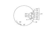
図1は、研磨装置100の一例を例示する。研磨装置100は、回転可能なディスク形状のプラテン120を含み、プラテン120上に、研磨パッド110が位置される。プラテンは、軸125の周りで回転するように動作可能である。例えば、モータ121が、駆動シャフト124をターンさせて、プラテン120を回転させることができる。研磨パッド110は、例えば接着剤の層によってプラテン120に取外し可能に固定することができる。研磨パッド110は、外側研磨層112と、より軟質のバッキング層114とを有する2層研磨パッドでよい。
FIG. 1 illustrates an example of a
研磨装置100は、複合型スラリ/リンスアーム130を含むことができる。研磨中、アーム130は、スラリなどの研磨液132を研磨パッド110上に定量供給するように動作可能である。ただ1つのスラリ/リンスアーム130が図示されているが、キャリアヘッド当たり1つまたは複数の専用スラリアームなど、追加のノズルを使用することができる。また、研磨装置は、研磨パッド110を一貫した摩耗状態で保つように研磨パッド110を摩耗するために、研磨パッドコンディショナを含むこともできる。
The polishing
さらに、研磨装置100は、キャリアヘッド140を含むことができる。キャリアヘッド140は、研磨パッド110に対して基板10を保持するように動作可能であることがある。ただ1つのキャリアヘッド140が図示されているが、追加のキャリアヘッドを使用することができ、いくつかの実装形態では、追加のキャリアヘッドが好ましいことがある。そのような実施形態では、キャリアヘッドに関連付けられる個別に設定される研磨パラメータ(例えば、チャンバ圧力、保持リング圧力、および/またはキャリアヘッド回転速度)を用いて、各キャリアヘッド140を個別に制御することができる。
Further, the polishing
キャリアヘッド140は、可撓性膜144の下に基板10を保定するために、保持リング142を含むことができる。また、キャリアヘッド140は、膜によって画定される複数の個別に制御可能な加圧可能なチャンバ、例えば3つのチャンバ146a〜146cを含むこともでき、これらのチャンバ146a〜146cは、可撓性膜144の上、したがって基板10の背面の上の関連の区域148a〜148c(図2参照)に、個別に制御された量の圧力を印加することができる。可撓性膜144は、高強度シリコーンゴムなど弾性材料から形成することができる。図2を参照すると、中央区域148aは、実質的に円形でよく、残りの区域148b〜148eは、中央区域148aの周りの同心環状区域でよい。分かりやすくするために、図1および図2では3つのチャンバのみが例示されているが、2つのチャンバ、または4つ以上のチャンバ、例えば5つのチャンバがあってもよい。
The
図1を参照すると、キャリアヘッド140は、支持構造150、例えばカルーセルから懸架され、駆動シャフト152によってキャリアヘッド回転モータ154に接続され、それにより、キャリアヘッドは軸155の周りで回転することができる。任意選択で、キャリアヘッド140は、例えば、カルーセル150にあるスライダ上で、またはカルーセル自体の回転振動によって側方に振動することができる。動作時、プラテンは、プラテンの中心軸125の周りで回転され、キャリアヘッドは、キャリアヘッドの中心軸155の周りで回転されて、研磨パッドの上面にわたって側方に並進される。
Referring to FIG. 1, the
ここでも、ただ1つのキャリアヘッド140が示されているが、研磨パッド110の表面領域を効率的に使用することができるように、さらなる基板を保持するためにより多くのキャリアヘッドを提供することができる。したがって、同時研磨プロセスのために基板を保持するように適合されたキャリアヘッドアセンブリの数は、少なくとも一部は、研磨パッド110の表面積に基づかせることができる。
Again, although only one
また、研磨装置は、インシトゥモニタシステム160を含み、インシトゥモニタシステム160からのデータをコントローラ190によって使用して、以下に論じるように、研磨速度を調節するかどうかを決定する、または研磨速度に関する調節を決定することができる。インシトゥモニタシステム160は、光学モニタシステム、例えば分光モニタシステムや渦流モニタシステムを含むことができる。
The polishing apparatus also includes an in
一実施形態では、モニタシステム160は、光学モニタシステムである。研磨パッドを通る光学アクセスが、アパーチャ(すなわち、パッドを貫通する孔)または固体窓118を含むことによって提供される。固体窓118は、例えば研磨パッドのアパーチャに埋まるプラグとして研磨パッド110に固定することができ、例えば、研磨パッドに成形される、または接着剤で固定されるが、いくつかの実装形態では、固体窓は、プラテン120上に支持されて、研磨パッドのアパーチャ内に突出することができる。
In one embodiment,
光学モニタシステム160は、光源162と、光検出器164と、回路166とを含むことができ、回路166は、遠隔コントローラ190、例えばコンピュータと、光源162および光検出器164との間で信号を送受信するためのものである。1つまたは複数の光ファイバを使用して、光源162から研磨パッドの光学アクセスに光を伝送することができ、かつ基板10から反射された光を検出器164に伝送することができる。例えば、二分岐光ファイバ170を使用して、光源162から基板10に光を伝送することができ、かつ検出器164に光を伝送して戻すことができる。二分岐光ファイバは、光学アクセスの近位に位置決めされた幹線(trunk)172と、それぞれ光源162および検出器164に接続された2つの分岐線(branch)174および176とを含む。
The
いくつかの実装形態では、プラテンの上面は、凹部128を含むことができ、凹部128内に、二分岐ファイバのトランク172の一端を保持する光学ヘッド168が嵌められる。光学ヘッド168は、トランク172の上部と固体窓118との間の垂直距離を調節するためのメカニズムを含むことができる。
In some implementations, the top surface of the platen can include a
回路166の出力は、デジタル電子信号でよく、このデジタル電子信号は、駆動シャフト124のロータリカプラ129、例えばスリップリングを通って、光学モニタシステム用のコントローラ190に進む。同様に、光源は、コントローラ190からロータリカプラ129を通って光学モニタシステム160に進むデジタル電子信号における制御コマンドに応答して、オンまたはオフに切り替えることができる。あるいは、回路166は、ワイヤレス信号によってコントローラ190と通信することができる。
The output of
光源162は、白色光を放出するように動作可能であることがある。一実装形態では、放出される白色光は、200〜800ナノメートルの波長を有する光を含む。適切な光源は、キセノンランプまたはキセノン水銀ランプである。
The
光検出器164は、分光器でよい。分光器は、電磁スペクトルの一部分にわたる光の強度を測定するための光学機器である。適切な分光器は、格子分光器である。分光器に関する典型的な出力は、波長(または周波数)の関数としての光の強度である。
The
上述したように、光源162および光検出器164は、計算デバイス、例えばコントローラ190に接続することができ、コントローラ190は、光源162および光検出器164の動作を制御し、光源162および光検出器164の信号を受信するように動作可能である。計算デバイスは、研磨装置の近くに位置されたマイクロプロセッサ、例えばプログラマブルコンピュータを含むことができる。制御に関して、計算デバイスは、例えば、光源の活性化をプラテン120の回転と同期させることができる。また、コントローラ190は、光学モニタシステム160からのデータに基づいてターゲット圧力プロファイルを生成し、ターゲット圧力プロファイルを記憶し、また、ターゲット圧力プロファイルを実現するためにキャリアヘッド内のチャンバに関する1組の圧力を計算することができる。
As described above, the
いくつかの実装形態では、インシトゥモニタシステム160の光源162および検出器164は、プラテン120内に設置され、プラテン120と共に回転する。この場合、プラテンの運動により、センサが各基板を横切ってスキャンする。特に、プラテン120が回転するとき、コントローラ190は、各基板10が光学アクセスの上を通る直前に始まり、通った直後に終わる一連のフラッシュを光源162に放出させることができる。あるいは、計算デバイスは、各基板10が光学アクセスの上を通る直前に始まり、通った直後に終わる光を光源162に連続的に放出させることができる。いずれにせよ、検出器からの信号を、サンプリング期間にわたって統合して、サンプリング周波数でのスペクトル測定値を生成することができる。
In some implementations, the
動作時、コントローラ190は、例えば、光源の特定のフラッシュまたは検出器の時間フレームに関して、光検出器によって受信された光のスペクトルを表す情報を搬送する信号を受信することができる。したがって、このスペクトルは、研磨中にインシトゥで測定されるスペクトルである。
In operation, the
図3に示されるように、検出器がプラテン内に設置される場合、サンプリング周波数でのスペクトル測定を行う光学モニタシステムは、プラテンの回転(矢印204によって示される)により、窓108が1つのキャリアヘッド(例えば、第1の基板10aを保持するキャリアヘッド)の下を通るときに、第1の基板10aを横切る弧内の位置201でスペクトル測定を行う。例えば、各点201a〜201kは、第1の基板10aのモニタシステムによるスペクトル測定の位置を表す(点の数は例示であり、サンプリング周波数に応じて、例示したよりも多数または少数の測定値を取ることができる)。図示されるように、プラテンの1回の回転にわたって、基板10a上の異なる半径からスペクトルが得られる。すなわち、いくつかのスペクトルは、基板10aの中心により近い位置から得られ、いくつかは、エッジにより近い。
As shown in FIG. 3, when the detector is installed in the platen, an optical monitoring system that performs spectral measurements at the sampling frequency is such that the rotation of the platen (indicated by arrow 204) causes the
図1を参照して上述したように、チャンバ146a〜146cの加圧は、研磨パッド110に対する基板10の下方向圧力を制御する。一般に、チャンバによって膜の関連の区域に印加される圧力の大半は、研磨パッドに接する基板の前面の対応する区域に加えられる。しかし、ある量の印加圧力は、基板の前面での区域の間に「溢れる」ことがある(図4参照)。さらに、チャンバによって関連の区域内に印加される圧力は、完全には均一でないことがある。図4は、いくつかの圧力分布曲線を示し、各圧力分布曲線は、キャリアヘッド内の特定のチャンバが加圧されていると仮定したときの、基板の中心からの距離の関数としての、基板の前面に印加される圧力の例示的なグラフである。図4を参照すると、この例では、圧力分布曲線200aによって示されるように、チャンバ146aによって提供される少なくともいくらかの圧力が、基板10の両方の区域148aおよび148bに印加される。同様に、圧力分布曲線200bによって示されるように、チャンバ146bによって提供される少なくともいくらかの圧力が、各区域148a〜148cに印加され、圧力分布曲線200cによって示されるように、チャンバ146cによって提供される少なくともいくらかの圧力が、区域148cおよび148bに印加される。さらに、基板10の区域148aの内部でさえ、チャンバ146aによって印加される圧力は、完全には均一でない。
As described above with reference to FIG. 1, the pressurization of the chambers 146 a-146 c controls the downward pressure of the
いかなる特定の理論にも拘束されないが、圧力の溢れおよび不均一性は、膜144の可撓性に起因することがあり得る。すなわち、圧力下で、膜144のいくつかの部分は、元々画定されていた区域を越えて伸長される、または伸張させられることがある。さらに、やはりいかなる特定の理論にも拘束されないが、圧力の溢れは、基板10の厚さに起因することがある。例えば、基板10は、背面(すなわち膜144に接触する基板表面)に印加される圧力が、前面(すなわち研磨パッドに接触する基板表面)に伝播するときに区域の境界を越えて半径方向に広がるほど十分に厚いことがある。
Without being bound by any particular theory, pressure overflow and non-uniformity can be attributed to the flexibility of the
一般に、研磨システムは、研磨後の基板が基板表面にわたってターゲット表面プロファイル、例えばターゲット厚さを有するように制御される。ターゲット表面プロファイルは、基板表面にわたって均一(例えば平面)であることも、不均一であることもある。ターゲット表面プロファイルは、研磨システムの製造業者が手動で設定することができ、研磨システムの操作者、例えば半導体施設の従業員が手動で設定することができ、または、半導体施設での他のツールの性能の測定に基づいてコンピュータソフトウェアによって自動的に生成して、例えば他のツールによる不均一な堆積または除去を補償することもできる。 In general, the polishing system is controlled such that the polished substrate has a target surface profile, eg, target thickness, across the substrate surface. The target surface profile may be uniform (eg, planar) or non-uniform across the substrate surface. The target surface profile can be set manually by the polishing system manufacturer, can be set manually by an operator of the polishing system, eg, a semiconductor facility employee, or other tools in the semiconductor facility It can also be automatically generated by computer software based on performance measurements to compensate for non-uniform deposition or removal, for example by other tools.
上述したように、研磨速度(すなわち、材料が基板10から除去される速度)は、いくつかの研磨システムパラメータ、例えば、チャンバ圧力、保持リング圧力、キャリアヘッド回転速度、プラテン回転速度などに応じて変えることができる。したがって、そのようなパラメータの組合せが、研磨後の基板10の表面プロファイルを決定することができる。
As described above, the polishing rate (ie, the rate at which material is removed from the substrate 10) depends on several polishing system parameters, such as chamber pressure, retaining ring pressure, carrier head rotation rate, platen rotation rate, etc. Can be changed. Therefore, such a combination of parameters can determine the surface profile of the
コントローラ190は、ターゲット除去プロファイルを記憶するように構成することができる。コントローラ190は、ターゲット除去プロファイルを使用して、研磨システム20に関するプロセスパラメータ、例えばキャリアヘッド140のチャンバ146a〜146c内の圧力を設定する。ターゲット除去プロファイルは、基板の前面にわたって除去されることが望まれる材料の量を表す。いくつかの実装形態では、ターゲット除去プロファイルは、例えば、(例えば研磨前に計測学ステーションで、またはインシトゥモニタシステムによって測定される)基板10の初期表面プロファイルに基づいて、コントローラ190、またはターゲット除去プロファイルをコントローラ190に転送する別のコンピュータシステムによって決定することができる。例えば、ターゲット除去プロファイルは、
TRP=ISP−TSP (1)
として計算することができ、ここで、TRPは、ターゲット除去プロファイルであり、ISPは、初期表面プロファイルであり、TSPは、ターゲット表面プロファイルである。あるいは、初期表面プロファイルが分かっていない場合には、初期表面プロファイルをデフォルト値に設定することができる。また、いくつかの状況では、研磨システムの操作者は、ターゲットプロファイルを実現することではなく、基板からターゲット量を除去することを望むことがある。さらに、いくつかの状況では、研磨システムの操作者は、ターゲット除去プロファイルを、例えば先験的な原理または以前の経験に基づいて単に設定することがある。この場合には、ユーザは、例えばユーザ入力によって、コントローラ190に対して、またはコントローラ190にターゲット除去プロファイルを転送する別のコンピュータシステムに対してターゲット除去プロファイルを生成することができる。
The
TRP = ISP-TSP (1)
Where TRP is the target removal profile, ISP is the initial surface profile, and TSP is the target surface profile. Alternatively, if the initial surface profile is not known, the initial surface profile can be set to a default value. Also, in some situations, an operator of the polishing system may desire to remove a target amount from the substrate rather than achieving a target profile. Further, in some situations, the operator of the polishing system may simply set the target removal profile, for example based on a priori principles or previous experience. In this case, the user can generate a target removal profile to the
コントローラ190は、プロセスパラメータに関する所与の1組の値に関して、予想除去プロファイル(すなわち、基板10の前面にわたって除去されると予想される材料の量)を生成して記憶する。
The
一般に、予想除去プロファイルがターゲット除去プロファイルに(正確な一致も含めて)良く近似するように、プロセスパラメータ、例えばキャリアヘッドのチャンバ内の圧力に関する値を選択することが有利である。例えば、予想除去プロファイルがターゲット除去プロファイルに良く近似する場合、実際の除去プロファイル、すなわち研磨時に基板から実際に除去される量も、ターゲット除去ファイルに良く近似するはずである。 In general, it is advantageous to select values for process parameters, such as pressure in the chamber of the carrier head, so that the expected removal profile closely approximates the target removal profile (including an exact match). For example, if the expected removal profile closely approximates the target removal profile, the actual removal profile, ie, the amount actually removed from the substrate during polishing, should also closely approximate the target removal file.
本明細書で述べる除去プロファイルは、基板表面から除去される材料の量として、または多義的に、材料除去速度として(例えば、研磨に費やされる実際の時間または予想時間で除去プロファイルを割ることによって)表現することができることに留意すべきである。さらに、計算のためにデータが一貫した単位に変換される限り、計算に使用されるデータを様々な異なる単位で記憶することができることも理解すべきである。 The removal profile described herein is as the amount of material removed from the substrate surface, or broadly as the material removal rate (eg, by dividing the removal profile by the actual or expected time spent polishing). It should be noted that it can be expressed. Furthermore, it should be understood that the data used for the calculation can be stored in a variety of different units, as long as the data is converted into a consistent unit for calculation.
いくつかの実装形態では、予想除去プロファイルは、研磨パラメータ、例えばチャンバ146a〜146cによって提供される圧力の線形関数として計算することができる。例えば、特定のチャンバ内での圧力の増加は、研磨パッドに対する基板の圧力の線形増加、したがって研磨速度の線形増加、したがって除去される量の線形増加が生じることがある。特に、基板上の複数の異なる点、例えば基板の中心から異なる半径方向距離にある点に関して、除去量は、研磨パラメータ、例えばチャンバ内の圧力の線形結合として計算することができる。
In some implementations, the expected removal profile can be calculated as a linear function of the polishing parameters, eg, the pressure provided by the
研磨パラメータと除去プロファイルの関係は、測定されたデータに基づいて決定することができる。例えば、テスト基板に関して除去プロファイルを測定することができ、各テスト基板が、研磨パラメータに関する異なる1組の値を使用して研磨される。特に、研磨パラメータに関する1組のベースライン値の下で1つの基板を研磨することができ、その基板から、ベースライン除去プロファイルが測定される。次いで、プロセスによって設定することができる各パラメータに関して、そのパラメータをベースライン値とは異なる調節された値に設定して(しかし他のパラメータはそれらのベースライン値に設定して)さらなる基板が研磨され、そのさらなる基板から、調節された除去プロファイルが測定される。 The relationship between the polishing parameter and the removal profile can be determined based on the measured data. For example, a removal profile can be measured for a test substrate, and each test substrate is polished using a different set of values for polishing parameters. In particular, a substrate can be polished under a set of baseline values for polishing parameters, from which a baseline removal profile is measured. Then, for each parameter that can be set by the process, set the parameter to an adjusted value that is different from the baseline value (but set the other parameters to their baseline value) and further substrate polishing From that additional substrate, the adjusted removal profile is measured.
いくつかの実装形態では、予想除去プロファイルは、
ERP=BRP+[K][P’]*BRP (2)
として計算することができ、ここで、ERPは、予想除去プロファイルであり、BRPは、ベースライン除去プロファイルであり、[K]は、パラメータの総数Nに等しい数の列と、プロファイルが測定される基板表面上での半径方向位置の総数Mに等しい数の行とを有する定数の行列であり、[P’]は、調節される研磨システムパラメータのベクトルである。位置の総数Mは、キャリアヘッド内のチャンバの数よりも大きくすることができ、また、制御可能なパラメータの総数Nよりも大きくすることができる。
In some implementations, the expected removal profile is
ERP = BRP + [K] [P ′] * BRP (2)
Where ERP is the expected removal profile, BRP is the baseline removal profile, [K] is a number of columns equal to the total number N of parameters, and the profile is measured A matrix of constants with a number of rows equal to the total number M of radial positions on the substrate surface, [P ′] is a vector of polishing system parameters to be adjusted. The total number M of positions can be greater than the number of chambers in the carrier head and can be greater than the total number N of controllable parameters.
ベースライン除去プロファイルは、1組のデフォルト研磨パラメータP01、P02、…、P0Nでテストウエハを研磨し、研磨後の(例えば計測学ステーションで)測定された表面プロファイルを初期表面プロファイルと比較することによって決定することができる。例えば、ベースライン除去プロファイルは、
BRP=ISP−BSP (3)
として計算することができ、ここで、BRPは、ベースライン除去プロファイルであり、ISPは、初期表面プロファイルであり、BSPは、ベースラインパラメータP01、P02、…、P0Nでテスト基板を研磨することにより実現されるベースライン表面プロファイルである。
A baseline removal profile is obtained by polishing a test wafer with a set of default polishing parameters P0 1 , P0 2 ,..., P0 N , and comparing the measured surface profile after polishing (eg, at a metrology station) with an initial surface profile. Can be determined. For example, the baseline removal profile is
BRP = ISP-BSP (3)
Where BRP is the baseline removal profile, ISP is the initial surface profile, and BSP is polishing the test substrate with the baseline parameters P0 1 , P0 2 ,..., P0 N It is a baseline surface profile realized by doing.
行列[K]の定数は、ベースライン除去プロファイルと、調節された除去プロファイルとに基づいて決定することができる。上述したように、調節された除去プロファイルは、各パラメータに関して、そのパラメータを修正しながら、1度に1基板ずつ、さらなる基板を研磨することによって生成することができる。例えば、調節された除去プロファイルは、以下の式に従って、各修正されたパラメータに関して計算することができる。
ARPi=ISP−ASPi (4)
ここで、ARPiは、第iの研磨パラメータの調節から得られる調節された除去プロファイルであり、ISPは、初期表面プロファイルであり、ASPiは、第iのパラメータを調節した結果として測定される調節された表面プロファイルである。特に、行列[K]の定数値は、
として計算することができ、ここで、Kx,iは、第iのパラメータに関する、基板プロファイル位置xに対応する行列[K]の値であり、ARPx,iは、第iの調節されたパラメータに関する、半径方向位置xで除去された材料の量であり、BRPxは、前に計算されたベースライン除去プロファイルに従って半径方向位置xで除去された材料の量であり、PAiは、第iの調節された除去プロファイルを生成するために使用される第iのパラメータ値であり、P0iは、ベースライン除去プロファイルに関する第iのパラメータ値である。したがって、行列[K]は、
と表現することができ、ここで、Mは、プロファイル測定値が取られる半径方向基板位置xの総数であり、Nは、パラメータの総数である。ベクトル[P’]、P1’、P2’、…、PN’の変数表現は、
![]()
によって定義され、ここで、Pi’は、第iのパラメータに対応するベクトル[P’]の値であり、P0iは、ベースライン除去プロファイルに関する第iのパラメータ値であり、Piは、可変の提案されるパラメータ値である。したがって、予想除去プロファイルは、
と表現することができ、ここで、ERPは、予想除去プロファイルであり、BRPは、ベースライン除去プロファイルであり、行列[K]およびベクトル[P’]に関する値は、式(5)および(7)を参照して上述したように計算される。
The matrix [K] constants can be determined based on the baseline removal profile and the adjusted removal profile. As described above, an adjusted removal profile can be generated for each parameter by polishing additional substrates, one substrate at a time, while modifying that parameter. For example, an adjusted removal profile can be calculated for each modified parameter according to the following equation:
ARP i = ISP-ASP i (4)
Where ARP i is the adjusted removal profile resulting from adjustment of the i th polishing parameter, ISP is the initial surface profile, and ASP i is measured as a result of adjusting the i th parameter. An adjusted surface profile. In particular, the constant value of the matrix [K] is
Where K x, i is the value of the matrix [K] corresponding to the substrate profile position x for the i th parameter, and ARP x, i is the i th adjusted Is the amount of material removed at radial location x with respect to the parameter, BRP x is the amount of material removed at radial location x according to the previously calculated baseline removal profile, and PA i is the first i is the i th parameter value used to generate the adjusted removal profile for i, and P0 i is the i th parameter value for the baseline removal profile. Therefore, the matrix [K] is
Where M is the total number of radial substrate positions x at which profile measurements are taken and N is the total number of parameters. Vector [P '], P 1' , P 2 ', ..., P N' is variable representation of,
![]()
Where P i ′ is the value of the vector [P ′] corresponding to the i th parameter,
Where ERP is the expected removal profile, BRP is the baseline removal profile, and the values for matrix [K] and vector [P ′] are given by equations (5) and (7 ) And calculated as described above.
いくつかの実装形態では、実験測定から生成される様々なプロファイル、例えばベース除去プロファイルおよび調節された除去プロファイルは、各区域の下の複数の位置、例えば各チャンバの下の複数の位置に関する測定された除去値を含む。同様に、計算された予想除去量は、各区域の下の複数の位置、例えば各チャンバの下の複数の位置での予想除去量に関する計算された値を含む。いくつかの実装形態では、プロファイル、例えば、ベース除去プロファイル、調節された除去プロファイル、および予想除去プロファイルは、基板上の20〜300の位置に関する値を含む。例えば、それらのプロファイルは、1mmの一定の間隔での基板上の位置に関する値を含むことができる。 In some implementations, various profiles generated from experimental measurements, e.g., base removal profile and adjusted removal profile, are measured for multiple locations under each area, e.g., multiple locations under each chamber. Includes removal values. Similarly, the calculated expected removal includes a calculated value for the expected removal at a plurality of locations under each area, eg, a plurality of locations under each chamber. In some implementations, the profiles, eg, base removal profile, adjusted removal profile, and expected removal profile include values for 20-300 locations on the substrate. For example, the profiles can include values for positions on the substrate at regular intervals of 1 mm.
いくつかの実装形態では、パラメータの適切な組合せは、予想除去プロファイルとターゲット除去プロファイルの差を最小にするそれぞれのパラメータを求めることによって決定することができる。すなわち、ERP−TRPの値が最小にされる。多くの場合に、ターゲット除去プロファイルに等しい予想除去プロファイルを提供する、したがってERP−TRP=0を与える1つまたは複数の異なるパラメータセットを数学的に決定することができる。他の場合には、以下の式を使用することによって、予想除去プロファイルとターゲット除去プロファイルの差の値を、許容範囲内の非ゼロ値に最小化することができる。
ここで、Δは、差の値であり、ERPxは、基板上の半径方向位置xでの予想除去プロファイルの変数値であり、TRPxは、半径方向位置xでのターゲット除去プロファイルの定数値である。Piの値は、ターゲット除去プロファイルを良く近似する予想除去プロファイルを求めるために計算することができる。
In some implementations, the appropriate combination of parameters can be determined by determining the respective parameters that minimize the difference between the expected removal profile and the target removal profile. That is, the value of ERP-TRP is minimized. In many cases, one or more different parameter sets can be determined mathematically that provide an expected removal profile equal to the target removal profile, thus giving ERP-TRP = 0. In other cases, the value of the difference between the expected removal profile and the target removal profile can be minimized to an acceptable non-zero value by using the following equation:
Where Δ is the difference value, ERP x is the variable value of the expected removal profile at radial position x on the substrate, and TRP x is the constant value of the target removal profile at radial position x. It is. The value of P i can be calculated to determine the expected removal profile to improve approximates the target removal profile.
いくつかの例では、反復プロセス(例えば、最適化のニュートン法)を、式(9)と共に使用して、パラメータ値の適当な組合せを決定し、推定圧力プロファイルとターゲット圧力プロファイルの最小の差を求める、例えばΔに関する最小値を求めることができる。例えば、市販のソルバ機能(例えば、Microsoft Excelソルバ機能、MATLABソルバ機能、および/またはWolfram Mathematicaソルバ機能など)を使用して、パラメータ値の適当な組合せを決定することができる。いくつかの場合には、パラメータ値の複数の適切な組合せが存在することがある。 In some examples, an iterative process (eg, Newton's method of optimization) is used with Equation (9) to determine the appropriate combination of parameter values and to determine the minimum difference between the estimated pressure profile and the target pressure profile. For example, a minimum value for Δ can be obtained. For example, commercially available solver functions (e.g., Microsoft Excel solver function, MATLAB Lab solver function, and / or Wolfram Mathematica solver function, etc.) can be used to determine the appropriate combination of parameter values. In some cases, there may be multiple suitable combinations of parameter values.
上述したようにパラメータ値の適当な組が決定されると、コントローラ190は、パラメータ値を記憶し、それに従って、研磨技法を実行して、ターゲット表面プロファイルを有する1つまたは複数の基板を提供するように構成することができる。
Once the appropriate set of parameter values is determined as described above, the
ほとんどの場合に、すべての他のパラメータ値が一定に保たれるときには、基板10上の特定の位置での研磨速度は、研磨パッド上で、基板のその位置で基板に印加される圧力と線形に変化することができる。
In most cases, when all other parameter values are kept constant, the polishing rate at a particular location on the
別の実装形態では、コントローラ190は、ターゲット圧力プロファイルを記憶するように構成することができる。コントローラ190は、ターゲット圧力プロファイルを使用して、キャリアヘッド140のチャンバ146a〜146c内の圧力を設定する。ターゲット圧力プロファイルは、研磨パッドに対して基板の前面によって印加すべき所望の圧力を表す。いくつかの実装形態では、ターゲット圧力プロファイルは、ターゲット表面プロファイルを実現するのに必要な研磨速度を生成するはずの圧力分布とみなすことができる。いくつかの実装形態では、ターゲット圧力プロファイルは、例えば、(例えば研磨前に計測学ステーションで、またはインシトゥモニタシステムによって測定される)基板10の初期表面プロファイル、および研磨速度と研磨圧力の既知の関係に基づいて、コントローラ190、またはターゲット圧力プロファイルをコントローラ190に転送する別のコンピュータシステムによって決定することができる。すなわち、ターゲット圧力プロファイルは、
TPP=m*(ISP−TSP) (10)
として計算することができ、ここで、TPPは、ターゲット圧力プロファイルであり、ISPは、初期表面プロファイルであり、TSPは、ターゲット表面プロファイルであり、mは、経験的に決定される定数である。あるいは、初期表面プロファイルが分かっていない場合には、初期表面プロファイルをデフォルト値に設定することができる。また、いくつかの状況では、研磨システムの操作者は、ターゲットプロファイルを実現することではなく、基板からターゲット量を除去することを望むことがある。この場合、ターゲット圧力プロファイルは、単に、除去するターゲット量の線形関数である。さらに、いくつかの状況では、研磨システムの操作者は、ターゲット研磨プロファイルを、例えば先験的な原理または以前の経験に基づいて単に設定することがある。この場合には、ユーザは、例えばユーザ入力によって、コントローラ190、またはコントローラ190に転送する別のコンピュータシステムに対してターゲット圧力プロファイルを生成することができる。
In another implementation, the
TPP = m * (ISP-TSP) (10)
Where TPP is the target pressure profile, ISP is the initial surface profile, TSP is the target surface profile, and m is a constant determined empirically. Alternatively, if the initial surface profile is not known, the initial surface profile can be set to a default value. Also, in some situations, an operator of the polishing system may desire to remove a target amount from the substrate rather than achieving a target profile. In this case, the target pressure profile is simply a linear function of the target amount to be removed. Further, in some situations, the operator of the polishing system may simply set the target polishing profile based on, for example, a priori principles or previous experience. In this case, the user can generate a target pressure profile for the
コントローラ190は、予想圧力プロファイル(すなわち、チャンバ146a〜146cが加圧されるときに予想される研磨パッド上の基板10の前面にわたる圧力分布)を生成および記憶することができる。いくつかの実装形態では、ターゲット圧力プロファイルは、チャンバ146a〜146cによって印加されると予想される圧力プロファイルによって近似することができる。一般に、ターゲット圧力プロファイルを予想圧力プロファイルと良く近似することが有利である。例えば、ターゲット圧力プロファイルを予想圧力プロファイルと良く近似することによって、研磨後のターゲット表面プロファイルの良い近似である基板10の実際の前面プロファイルが生じることがある。
The
いくつかの実装形態では、研磨パッドに対して基板によって印加される予想圧力は、チャンバ146a〜146cによって提供される圧力の線形関数として計算することができる。例えば、特定のチャンバ内での圧力の増加によって、研磨パッドに対する基板の圧力の線形増加、したがって研磨速度の線形増加が生じることがある。特に、基板上の複数の異なる点、例えば基板の中心から異なる半径方向距離にある点に関して、予想圧力は、チャンバ内の圧力の線形結合として計算することができる。例えば、推定圧力は、
![]()
として計算することができ、ここで、EPxは、位置xで印加される推定圧力であり、Piは、キャリアヘッド内のN個のチャンバのうちの第iのチャンバ内での圧力であり、Ai,xは定数である。上述したように、位置xは、基板の中心からの半径方向距離でよい。
In some implementations, the expected pressure applied by the substrate against the polishing pad can be calculated as a linear function of the pressure provided by the
![]()
Where EP x is the estimated pressure applied at position x and P i is the pressure in the i th chamber of the N chambers in the carrier head. , A i, x are constants. As described above, the position x may be a radial distance from the center of the substrate.
チャンバ圧力と印加圧力の関係、例えば定数Ai,xの値は、例えば、測定されたデータに基づいて決定することができる。いくつかの例では、圧力センサ(例えば、埋め込まれた1次元または2次元の圧力センサアレイを有する実質的に平面のシート)を、基板10の前面と、剛性支持体または研磨パッド110との間に挿入することができる。チャンバ146a〜146cの少なくとも1つが、ベースライン圧力(例えば、約0〜20psiの間)で加圧される。測定ツールによって提供される測定値は、ベースラインチャンバ圧力が印加されるときに基板の前面にわたって1つまたは複数の位置(例えば、約1〜100の間の位置)で基板10に加えられる下方向圧力を反映することができる。いくつかの実装形態では、測定値は、基板10の中心から半径方向距離で規則的にまたは不規則に間隔を空けた位置で記録される。個別に制御可能なチャンバよりも多くの測定値が存在する。いくつかの実装形態では、測定値は、特定のチャンバの下の位置で記録される。例えば、複数の測定値の第1の組を、チャンバ146aの下で記録することができ、複数の測定値の第2の組を、チャンバ146bの下で記録することができる。
The relationship between the chamber pressure and the applied pressure, for example, the value of the constant A i, x can be determined based on measured data, for example. In some examples, a pressure sensor (eg, a substantially planar sheet having an embedded one-dimensional or two-dimensional pressure sensor array) is placed between the front surface of the
いくつかの実装形態では、チャンバ146a〜146cは、1つずつ、ベースライン圧力まで加圧され、他のチャンバは加圧されない。この時点で、測定値が、基板10の前面にわたって記録される(いくつかの例では、チャンバは、1つずつ、異なるベースライン圧力まで加圧される)。次いで、記録された各チャンバに基づく圧力分布を組み合わせて、基板の前面の区域にわたる圧力の溢れを反映する総計の圧力分布を提供することができる(図4参照)。いくつかの実装形態では、各定数Ai,xの値は、単に、(圧力分布プロファイルからの)特定の点での測定された下方向圧力を、測定のためにチャンバに印加されたベースライン圧力で割ることによって計算することができる。
In some implementations, the
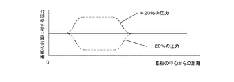
いくつかの例では、様々なチャンバ圧力それぞれの下での(上述したように記録される)各チャンバに関する複数の圧力分布を測定することができる。複数の圧力分布を併せて推定圧力プロファイルの計算に使用することができる。近似の精度を高めるために、各チャンバに関して、様々なチャンバ圧力それぞれで複数の圧力分布を記録することが有利であることがある。図5は、異なるチャンバ圧力で基板の前面にわたって測定される圧力分布を示す。図示されるように、圧力分布は、ベースラインチャンバ圧力の下で、ならびにベースラインよりも20%高いチャンバ圧力および20%低いチャンバ圧力の下で測定された。 In some examples, multiple pressure distributions for each chamber (recorded as described above) under each of the various chamber pressures can be measured. Multiple pressure distributions can be used together to calculate the estimated pressure profile. To increase the accuracy of the approximation, it may be advantageous to record multiple pressure distributions for each chamber at each of the various chamber pressures. FIG. 5 shows the pressure distribution measured across the front surface of the substrate at different chamber pressures. As shown, pressure distribution was measured under baseline chamber pressure and under 20% higher and 20% lower chamber pressure than baseline.
各チャンバに関する複数の圧力分布が提供されるとき、推定圧力は、
として計算することができ、ここで、EPxは、位置xで印加される推定圧力であり、Piは、キャリアヘッド内のN個のチャンバのうちの第iのチャンバ内での圧力であり、Ai,xおよびBi,xは定数である。ここでも、位置xは、基板の中心からの半径方向距離でよい。
When multiple pressure distributions for each chamber are provided, the estimated pressure is
Where EP x is the estimated pressure applied at position x and P i is the pressure in the i th chamber of the N chambers in the carrier head. , A i, x and B i, x are constants. Again, the position x may be a radial distance from the center of the substrate.
いくつかの実装形態では、定数Ai,xおよびBi,xの値は、各チャンバiに関して、以下の連立方程式を解くことによって計算することができる。
MPi,x,1=Ai,x*Pi,1+Bi,x (14)
MPi,x,2=Ai,x*Pi,2+Bi,x (15)
ここで、MPi,x,1およびMPi,x,2は、チャンバiがそれぞれ第1のチャンバ圧力P1および第2のチャンバ圧力P2で加圧されるときの、基板上の半径方向位置xでの測定された圧力である。
In some implementations, the values of the constants A i, x and B i, x can be calculated for each chamber i by solving the following simultaneous equations:
MP i, x, 1 = A i, x * P i, 1 + B i, x (14)
MP i, x, 2 = A i, x * P i, 2 + B i, x (15)
Here, MP i, x, 1 and MP i, x, 2 is when the chamber i is pressurized in the first chamber pressure P 1 and the second chamber pressure P 2, respectively, the radial direction of the substrate The measured pressure at position x.
いくつかの実装形態では、他のチャンバも加圧された状態での各チャンバに関する1つまたは複数の圧力分布が測定される。例えば、図6は、チャンバ146aおよび146cが加圧されるベースラインチャンバ圧力よりも20%高い圧力および20%低い圧力でチャンバ146bが加圧される圧力分布の集合を示す。図6は、例えば各チャンバからの均一な圧力を同じ圧力で例示するが、様々なチャンバは、(チャンバを加圧すべきではあるものの)同じ圧力である必要はなく、得られる基板の前面での圧力は、均一である必要はない。いかなる特定の理論にも拘束されないが、それぞれのチャンバを画定する膜材料が伸張または隆起する度合い(したがって圧力分布に対する影響)は、隣接するチャンバ内の圧力に依存することがある。したがって、典型的には動作時にチャンバが少なくとも一部加圧されるので、このようにして測定された圧力分布は、チャンバ圧力の変化による基板の前面での圧力の変動をより正確に反映することができる。
In some implementations, one or more pressure distributions for each chamber are measured with the other chambers also pressurized. For example, FIG. 6 shows a set of pressure distributions in which
所与のチャンバに関して、圧力分布は、1つ、2つ、または3つ以上のチャンバ圧力で測定することができる(3つ以上のチャンバ圧力の場合、推定圧力は、1組の個別の線分として処理することができ、または単一の線形関数をデータに当て嵌めることができる)。所与のチャンバに関して圧力分布が測定されるチャンバ圧力の数は、利用可能な計算資源、精度要件、またはデータ収集のための時間のバランスによって支配されることがある。 For a given chamber, the pressure distribution can be measured at one, two, three or more chamber pressures (for three or more chamber pressures, the estimated pressure is a set of individual line segments. Or a single linear function can be fitted to the data). The number of chamber pressures for which the pressure distribution is measured for a given chamber may be governed by available computing resources, accuracy requirements, or a balance of time for data collection.
いくつかの実装形態では、各チャンバに関する可変の個別の圧力分布について予想圧力プロファイルを記述する1つまたは複数の式は、ターゲット圧力プロファイルを良く近似するように、反復プロセス(例えば、最適化のニュートン法)によって最適化することができる。反復プロセスの第1のステップは、(1つまたは複数の)ベースラインチャンバ圧力で測定された圧力分布プロファイルをターゲット圧力プロファイルと比較することでよい。次いで、比較に基づいて、式の少なくとも1つの変数(例えば、チャンバの1つに基づく圧力分布)を調節することができ、調節された変数に基づいて予想圧力プロファイルを計算することができる。次いで、予想圧力プロファイルを、ターゲット圧力プロファイルと比較することができ、別の調節を行うことができる。反復調節および比較は、ターゲット圧力プロファイルを良く近似する予想圧力プロファイルが決定されるまで(すなわち、比較値のしきい値に達するまで)続けることができる。 In some implementations, one or more equations describing the expected pressure profile for a variable individual pressure distribution for each chamber may be an iterative process (e.g., an optimization Newton) to better approximate the target pressure profile. Method). The first step of the iterative process may be to compare the pressure distribution profile measured at baseline chamber (s) with the target pressure profile. Based on the comparison, at least one variable of the equation (eg, a pressure distribution based on one of the chambers) can then be adjusted, and an expected pressure profile can be calculated based on the adjusted variable. The expected pressure profile can then be compared to the target pressure profile and other adjustments can be made. Iterative adjustments and comparisons can continue until an expected pressure profile that closely approximates the target pressure profile is determined (ie, until a comparison value threshold is reached).
いくつかの例では、ターゲット圧力プロファイル(TPP)は、基板表面上のそれぞれの半径方向位置で複数のターゲット圧力に関して記述することができる。同様に、推定圧力プロファイル(EPP)は、基板表面上のそれぞれの半径方向位置での複数の予想圧力(すなわちEPx−上の式(12)および(13)参照)に関して記述することができる。上述したように、任意の位置での予想圧力を、チャンバ圧力の関数として計算することができる。したがって、ターゲット圧力プロファイルの適切な近似を提供するためのチャンバ圧力の組合せは、推定圧力プロファイルとターゲット圧力プロファイルの差を最小にするそれぞれのチャンバ圧力を求めることによって決定することができる。すなわち、EPP−TPPの値が最小にされる。 In some examples, a target pressure profile (TPP) can be described for multiple target pressures at each radial location on the substrate surface. Similarly, the estimated pressure profile (EPP) can be described in terms of multiple expected pressures at each radial location on the substrate surface (ie, EP x- see equations (12) and (13) above). As described above, the expected pressure at any location can be calculated as a function of chamber pressure. Thus, the combination of chamber pressures to provide an appropriate approximation of the target pressure profile can be determined by determining the respective chamber pressure that minimizes the difference between the estimated pressure profile and the target pressure profile. That is, the value of EPP-TPP is minimized.
例えば、例えば自乗または絶対値の和を使用して、推定圧力プロファイルとターゲット圧力プロファイルの差の値を計算することができ、この差を最小にするようにチャンバ圧力の値を計算することができる。例えば、これは、以下の式の1つを使用することによって行うことができる。
![]()
ここで、Δは、差の値であり、TPxは、基板上のM個の半径方向位置のうちの第xの半径方向位置で印加すべきターゲット圧力であり、Piは、キャリアヘッド内のN個のチャンバのうちの第iのチャンバ内の圧力であり、Ai,xおよびBi,xは、前に測定されたデータに基づいて決定される定数である。Piの値は、Δに関する最小値を求めるために計算することができる。
For example, the value of the difference between the estimated pressure profile and the target pressure profile can be calculated, for example using the square or the sum of absolute values, and the chamber pressure value can be calculated to minimize this difference. . For example, this can be done by using one of the following equations:
![]()
Where Δ is the difference value, TP x is the target pressure to be applied at the x th radial position of the M radial positions on the substrate, and P i is in the carrier head Of the N chambers, and A i, x and B i, x are constants determined based on previously measured data. The value of P i can be calculated to determine the minimum values for delta.
いくつかの例では、反復プロセス(例えば、最適化のニュートン法)を、式(16)または(17)と共に使用して、チャンバ圧力の適当な組合せを決定し、推定圧力プロファイルとターゲット圧力プロファイルの最小の差を求める、例えばΔに関する最小値を求めることができる。例えば、市販のソルバ機能を使用して、チャンバ圧力の適当な組合せを決定することができる。いくつかの場合には、チャンバ圧力の複数の適切な組合せが存在することがある。 In some examples, an iterative process (eg, Newton's method of optimization) is used in conjunction with equation (16) or (17) to determine the appropriate combination of chamber pressures and the estimated and target pressure profiles. A minimum difference can be determined, for example, a minimum value for Δ can be determined. For example, a commercially available solver function can be used to determine an appropriate combination of chamber pressures. In some cases, there may be multiple suitable combinations of chamber pressures.
許容範囲内の予想圧力プロファイルが決定されると、測定されたベースライン圧力分布に内挿および/または外挿技法を適用して(他の既知の数学的近似技法を使用することもできる)、各チャンバに関する対応するチャンバ圧力を決定することができる。単一のベースライン圧力からの圧力分布を使用するとき、ゼロスケール圧力分布を仮定することが必要であることがある(すなわち、チャンバが加圧されていないとき、印加される研磨圧力はほとんどないか、または全くない)。 Once the expected pressure profile within an acceptable range is determined, apply interpolation and / or extrapolation techniques to the measured baseline pressure distribution (other known mathematical approximation techniques can also be used) A corresponding chamber pressure for each chamber can be determined. When using a pressure distribution from a single baseline pressure, it may be necessary to assume a zero-scale pressure distribution (ie, there is little polishing pressure applied when the chamber is not pressurized) Or none at all).
図7および図8を参照すると、例示的なフローチャートが例示される。いくつかの場合には、図7に示されるプロセスステップは、研磨装置100の製造業者の1名または複数名の従業員が行うことができる。例えば、上述したように、各チャンバに関する1つまたは複数の圧力分布を製造業者が測定および記録することができる(ステップ702)。上述したように、これらの圧力分布を使用して、例えば定数Ai,xおよびBi,xを計算することによって、チャンバ圧力と、研磨パッドに対する基板の下方向圧力との関係を計算(または他の方法で決定)することができる(ステップ704)。この情報は、研磨装置100の製造業者が半導体施設に提供することができる。
With reference to FIGS. 7 and 8, an exemplary flowchart is illustrated. In some cases, the process steps shown in FIG. 7 can be performed by one or more employees of the manufacturer of the
いくつかの場合には、図8に示されるプロセスステップを、半導体施設の1名または複数名の従業員が行うことができる。例えば、集積回路を形成するための平坦化技法の一部として、基板に関する適当なターゲット表面プロファイルを半導体施設で決定することができる(ステップ802)。基板の初期表面プロファイルを測定することができる(ステップ804)。例えば、基板の表面プロファイルは、研磨前に計測学ステーションで測定することができ、または研磨中にインシトゥモニタシステムによって測定することができる。研磨速度と、研磨パッドに対する基板の下方向圧力との関係を決定することができる(ステップ806)。いくつかの場合には、この情報は、研磨装置または研磨パッドの供給業者によって提供されるデータから得ることができる。いくつかの他の場合には、この関係は、半導体施設で、例えば定数m(式(10)参照)を実験的に決定することによって、経験的に決定することができる。いくつかの実装形態では、上述したように、初期表面プロファイル、ターゲット表面プロファイル、および研磨速度と圧力との関係に基づいて、ターゲット圧力プロファイルを決定することができる(ステップ808)。次いで、上述したように、チャンバ圧力と、基板表面にわたる、研磨パッドに接する基板に対する下方向圧力との既知の関係に基づいて、ターゲット圧力プロファイル、したがってターゲット表面プロファイルを実現するためのチャンバ圧力の適切な組合せを決定することができる(ステップ810)。 In some cases, the process steps shown in FIG. 8 may be performed by one or more employees at a semiconductor facility. For example, as part of a planarization technique to form an integrated circuit, an appropriate target surface profile for the substrate can be determined at the semiconductor facility (step 802). An initial surface profile of the substrate can be measured (step 804). For example, the surface profile of the substrate can be measured at a metrology station prior to polishing, or can be measured by an in situ monitor system during polishing. A relationship between the polishing rate and the downward pressure of the substrate relative to the polishing pad can be determined (step 806). In some cases, this information can be obtained from data provided by the polishing equipment or polishing pad supplier. In some other cases, this relationship can be determined empirically at a semiconductor facility, for example by experimentally determining the constant m (see equation (10)). In some implementations, the target pressure profile can be determined based on the initial surface profile, the target surface profile, and the relationship between polishing rate and pressure, as described above (step 808). Then, as described above, based on the known relationship between the chamber pressure and the downward pressure across the substrate surface relative to the substrate in contact with the polishing pad, the target pressure profile, and therefore the appropriate chamber pressure to achieve the target surface profile Possible combinations can be determined (step 810).
本明細書で使用する際、用語「基板」は、例えば、製品基板(例えば、複数のメモリまたはプロセッサダイを含む)、テスト基板、裸の基板、および格子基板を含むことができる。基板は、集積回路製造の様々な段階にあることがあり、例えば、基板は、裸のウエハであることがあり、あるいは1つまたは複数の堆積されたおよび/またはパターン形成された層を含むこともある。用語「基板」は、円形ディスクおよび矩形シートを含むことができる。 As used herein, the term “substrate” can include, for example, product substrates (eg, including multiple memories or processor dies), test substrates, bare substrates, and lattice substrates. The substrate can be at various stages of integrated circuit fabrication, for example, the substrate can be a bare wafer or can include one or more deposited and / or patterned layers. There is also. The term “substrate” can include circular disks and rectangular sheets.
本明細書で述べる本発明の実施形態およびすべての機能動作を、本明細書で開示した構造的手段およびそれらの構造的均等物を含めた、デジタル電子回路、またはコンピュータソフトウェア、ファームウェア、もしくはハードウェア、またはそれらの組合せで実装することができる。本発明の実施形態は、1つのプログラマブル処理装置、1つのコンピュータ、または複数の処理装置もしくはコンピュータなど、データ処理装置によって実行するため、またはそのようなデータ処理装置の動作を制御するために、1つまたは複数のコンピュータプログラム製品として実装することができ、すなわち、機械可読の非一時的な記憶デバイスや伝播信号などの情報担体で有形に具現化された1つまたは複数のコンピュータプログラムとして実装することができる。コンピュータプログラム(プログラム、ソフトウェア、ソフトウェアアプリケーション、またはコードとしても知られている)は、コンパイルされた言語または解釈された言語を含めた任意の形態のプログラミング言語で書くことができ、スタンドアローンプログラムとして、またはモジュール、コンポーネント、サブルーチン、もしくは計算環境で使用するのに適した他のユニットとして、任意の形態で配備することができる。コンピュータプログラムは、必ずしもファイルに対応しない。プログラムは、他のプログラムまたはデータを保持するファイルの一部に記憶することができ、対象のプログラムに専用の単一のファイルに記憶することもでき、または複数の調整されたファイル(例えば、1つまたは複数のモジュール、サブルーチン、もしくはコードのいくつかの部分を記憶するファイル)に記憶することもできる。コンピュータプログラムは、1つのコンピュータで、または1つの場所にある複数のコンピュータで、または複数の場所にわたって分散されて通信ネットワークによって相互接続された複数のコンピュータで実行されるように配備することができる。 Embodiments of the invention and all functional operations described herein are described in terms of digital electronic circuitry, or computer software, firmware, or hardware, including the structural means disclosed herein and their structural equivalents. , Or a combination thereof. Embodiments of the present invention are for execution by a data processing device, such as a programmable processing device, a computer, or a plurality of processing devices or computers, or for controlling the operation of such a data processing device. Can be implemented as one or more computer program products, i.e. implemented as one or more computer programs tangibly embodied in an information carrier such as a machine-readable non-transitory storage device or a propagated signal Can do. A computer program (also known as a program, software, software application, or code) can be written in any form of programming language, including compiled or interpreted languages, and as a stand-alone program, Or it can be deployed in any form as a module, component, subroutine, or other unit suitable for use in a computing environment. A computer program does not necessarily correspond to a file. The program can be stored in a portion of a file that holds other programs or data, can be stored in a single file dedicated to the subject program, or multiple coordinated files (eg, 1 One or more modules, subroutines, or files that store several portions of code). A computer program can be deployed to be executed on one computer, on multiple computers at one location, or on multiple computers distributed across multiple locations and interconnected by a communication network.
本明細書で述べるプロセスおよび論理フローは、1つまたは複数のコンピュータプログラムを実行する1つまたは複数のプログラマブル処理装置によって実施することができ、入力データに対して処理を行って出力を生成することによっていくつかの機能を行う。また、プロセスおよび論理フローは、専用論理回路、例えばFPGA(フィールドプログラマブルゲートアレイ)やASIC(特定用途向け集積回路)によって行うこともでき、装置は、そのような専用論理回路として実装することもできる。 The processes and logic flows described herein can be implemented by one or more programmable processing devices that execute one or more computer programs, processing input data and generating output. By doing some functions. The process and logic flow can also be performed by a dedicated logic circuit, such as an FPGA (Field Programmable Gate Array) or ASIC (Application Specific Integrated Circuit), and the device can also be implemented as such a dedicated logic circuit. .
上述した研磨装置および方法は、様々な研磨システムに適用することができる。研磨パッドもしくはキャリアヘッドのいずれか、または両方が、研磨表面と基板の相対運動を提供するように移動することができる。例えば、プラテンは、回転するのではなく、軌道を描くことがある。研磨パッドは、プラテンに固定された円形(または何らかの他の形状の)パッドでよい。終点検出システムのいくつかの態様が、直線的研磨システムに適用可能であることがあり、その場合、例えば、研磨パッドは、直線的に移動する連続的なベルトまたはリールツーリールベルトである。研磨層は、標準の(例えば、フィラーを含む、またはフィラーを含まないポリウレタンからなる)研磨材料、軟質材料、または固定砥粒材料でよい。相対的な位置決めを表す用語を使用すると、研磨表面と基板は、操作中に、垂直向きまたは何らかの他の向きで保持することができることを理解すべきである。 The polishing apparatus and method described above can be applied to various polishing systems. Either the polishing pad or the carrier head, or both, can be moved to provide relative movement of the polishing surface and the substrate. For example, the platen may draw a trajectory rather than rotating. The polishing pad may be a circular (or some other shape) pad secured to the platen. Some aspects of the endpoint detection system may be applicable to a linear polishing system, where, for example, the polishing pad is a continuous belt or a reel-to-reel belt that moves linearly. The abrasive layer may be a standard abrasive material (eg, made of polyurethane with or without filler), a soft material, or a fixed abrasive material. Using terms describing relative positioning, it should be understood that the polishing surface and the substrate can be held in a vertical orientation or some other orientation during operation.
本発明の特定の実施形態を説明してきた。以下の特許請求の範囲内には、他の実施形態がある。例えば、特許請求の範囲に記載する処置は、異なる順序で行うことができ、それでも望ましい結果を実現する。 A particular embodiment of the present invention has been described. Other embodiments are within the scope of the following claims. For example, the actions recited in the claims can be performed in a different order and still achieve desirable results.
Claims (15)
前記基板の前面での除去プロファイルの変動を前記制御可能なパラメータの変動に関係付けるデータを記憶することと、前記データが、前記基板の前記前面の複数の位置での除去量を含み、チャンバよりも多数の位置が存在し、
ターゲット除去プロファイルと、前記基板の前面での除去プロファイルの変動を前記パラメータの変動に関係付ける前記データから計算される予想除去プロファイルとの差を最小にするために、前記複数の制御可能なパラメータの各パラメータに関する値を決定することと、
前記複数の制御可能なパラメータの各パラメータに関する値を記憶することと
を含む方法。 A method for selecting values for a plurality of controllable parameters of a chemical mechanical polishing system comprising a carrier head having a plurality of zones for applying individually controllable pressures to a substrate, comprising:
Storing data relating removal profile variations at the front side of the substrate to variations in the controllable parameter, the data including removal amounts at a plurality of locations on the front side of the substrate, from a chamber There are many positions,
In order to minimize the difference between the target removal profile and the expected removal profile calculated from the data relating variations in the removal profile at the front side of the substrate to variations in the parameter, the plurality of controllable parameters Determining a value for each parameter;
Storing a value for each parameter of the plurality of controllable parameters.
ERP=BRP+[K][P’]*BRP
を計算することを含み、ここで、ERPが、予想除去プロファイルであり、BRPが、ベースライン除去プロファイルであり、[K]が、パラメータの総数Nに等しい数の列と、プロファイルが測定される基板表面上での半径方向位置の総数Mに等しい数の行とを有する定数の行列であり、[P’]が、調節された研磨システムパラメータの1列行列である請求項11に記載の方法。 Calculating the expected removal profile;
ERP = BRP + [K] [P ′] * BRP
Where ERP is the expected removal profile, BRP is the baseline removal profile, [K] is a number of columns equal to the total number N of parameters, and the profile is measured. 12. The method of claim 11, wherein the matrix is a constant having a number of rows equal to the total number M of radial positions on the substrate surface, and [P ′] is a one-column matrix of adjusted polishing system parameters. .
を含み、ここで、Piが、計算すべき前記研磨パラメータの値であり、P0iが、前記研磨パラメータに関する前記ベースライン値である請求項12に記載の方法。 The adjusted polishing system parameter is
Includes, where, P i is the value of the to be calculated the polishing parameters, P0 i The method of claim 12 wherein the baseline value for the polishing parameters.
と表現することができ、ここで、Mが、プロファイル測定値が取られる半径方向基板位置xの総数であり、Nが、パラメータの総数であり、前記行列の定数が、
を含み、ここで、Kx,iが、第iのパラメータに関する、基板プロファイル位置xに対応する行列[K]の値であり、ARPx,iが、第iの調節されたパラメータに関する、半径方向位置xで除去された材料の量であり、BRPxが、前に計算されたベースライン除去プロファイルに従って半径方向位置xで除去された材料の量であり、PAiが、第iの調節された除去プロファイルを生成するために使用される第iのパラメータ値であり、P0iが、ベースライン除去プロファイルに関する第iのパラメータ値である請求項14に記載の方法。 The matrix [K] is
Where M is the total number of radial substrate positions x at which profile measurements are taken, N is the total number of parameters, and the matrix constant is
Where K x, i is the value of the matrix [K] corresponding to the substrate profile position x for the i th parameter, and ARP x, i is the radius for the i th adjusted parameter The amount of material removed at directional position x, BRP x is the amount of material removed at radial position x according to the previously calculated baseline removal profile, and PA i is the i th adjusted 15. The method of claim 14, wherein the i th parameter value used to generate the removed removal profile, and P0 i is the i th parameter value for the baseline removal profile.
Applications Claiming Priority (3)
| Application Number | Priority Date | Filing Date | Title |
|---|---|---|---|
| US13/098,257 US8774958B2 (en) | 2011-04-29 | 2011-04-29 | Selection of polishing parameters to generate removal profile |
| US13/098,257 | 2011-04-29 | ||
| PCT/US2012/034702 WO2012148859A2 (en) | 2011-04-29 | 2012-04-23 | Selection of polishing parameters to generate removal profile |
Publications (2)
| Publication Number | Publication Date |
|---|---|
| JP2014513434A true JP2014513434A (en) | 2014-05-29 |
| JP2014513434A5 JP2014513434A5 (en) | 2015-09-17 |
Family
ID=47068573
Family Applications (1)
| Application Number | Title | Priority Date | Filing Date |
|---|---|---|---|
| JP2014508469A Pending JP2014513434A (en) | 2011-04-29 | 2012-04-23 | Selection of polishing parameters to generate removal profile |
Country Status (5)
| Country | Link |
|---|---|
| US (3) | US8774958B2 (en) |
| JP (1) | JP2014513434A (en) |
| KR (2) | KR101831309B1 (en) |
| TW (2) | TWI668078B (en) |
| WO (1) | WO2012148859A2 (en) |
Cited By (3)
| Publication number | Priority date | Publication date | Assignee | Title |
|---|---|---|---|---|
| JP2014061587A (en) * | 2012-08-28 | 2014-04-10 | Ebara Corp | Elastic film, and substrate holding apparatus |
| KR20170028369A (en) * | 2014-06-27 | 2017-03-13 | 어플라이드 머티어리얼스, 인코포레이티드 | Configurable pressure design for multizone chemical mechanical planarization polishing head |
| JP2022517729A (en) * | 2018-12-26 | 2022-03-10 | アプライド マテリアルズ インコーポレイテッド | Preston matrix generator |
Families Citing this family (19)
| Publication number | Priority date | Publication date | Assignee | Title |
|---|---|---|---|---|
| US8774958B2 (en) | 2011-04-29 | 2014-07-08 | Applied Materials, Inc. | Selection of polishing parameters to generate removal profile |
| JP5900196B2 (en) * | 2012-07-05 | 2016-04-06 | 株式会社Sumco | Wafer single-side polishing method and wafer single-side polishing apparatus |
| AU2012385250B2 (en) * | 2012-07-10 | 2017-08-03 | Equinor Energy As | Anisotropy parameter estimation |
| US9248544B2 (en) * | 2012-07-18 | 2016-02-02 | Applied Materials, Inc. | Endpoint detection during polishing using integrated differential intensity |
| JP6266493B2 (en) * | 2014-03-20 | 2018-01-24 | 株式会社荏原製作所 | Polishing apparatus and polishing method |
| KR102323430B1 (en) * | 2014-03-31 | 2021-11-09 | 가부시키가이샤 에바라 세이사꾸쇼 | Polishing apparatus and polishing method |
| WO2018005039A1 (en) * | 2016-06-30 | 2018-01-04 | Applied Materials, Inc. | Chemical mechanical polishing automated recipe generation |
| TWI794293B (en) * | 2017-09-25 | 2023-03-01 | 美商應用材料股份有限公司 | Semiconductor fabrication using process control parameter matrix |
| TWI783037B (en) * | 2017-09-25 | 2022-11-11 | 美商應用材料股份有限公司 | Semiconductor fabrication using machine learning approach to generating process control parameters |
| JP7068831B2 (en) * | 2018-01-18 | 2022-05-17 | 株式会社荏原製作所 | Polishing equipment |
| WO2019176522A1 (en) * | 2018-03-12 | 2019-09-19 | 東京エレクトロン株式会社 | Substrate warpage correcting method, computer storage medium, and substrate warpage correction device |
| US20200055160A1 (en) * | 2018-08-14 | 2020-02-20 | Taiwan Semiconductor Manufacturing Co., Ltd. | Chemical mechanical polishing method and apparatus |
| EP3640972A1 (en) * | 2018-10-18 | 2020-04-22 | ASML Netherlands B.V. | System and method for facilitating chemical mechanical polishing |
| TW202042969A (en) * | 2019-02-28 | 2020-12-01 | 美商應用材料股份有限公司 | Controlling chemical mechanical polishing pad stiffness by adjusting wetting in the backing layer |
| US11282755B2 (en) | 2019-08-27 | 2022-03-22 | Applied Materials, Inc. | Asymmetry correction via oriented wafer loading |
| US20220283554A1 (en) * | 2021-03-05 | 2022-09-08 | Applied Materials, Inc. | Control of processing parameters for substrate polishing with substrate precession |
| US11919121B2 (en) | 2021-03-05 | 2024-03-05 | Applied Materials, Inc. | Control of processing parameters during substrate polishing using constrained cost function |
| CN113159121B (en) * | 2021-03-16 | 2022-07-19 | 华中科技大学 | Priori knowledge model-based robot polishing removal prediction method and device |
| US20220362903A1 (en) * | 2021-05-12 | 2022-11-17 | Taiwan Semiconductor Manufacturing Co., Ltd. | Multiple polishing heads with cross-zone pressure element distributions for cmp |
Citations (3)
| Publication number | Priority date | Publication date | Assignee | Title |
|---|---|---|---|---|
| JP2006043873A (en) * | 2004-07-09 | 2006-02-16 | Ebara Corp | Prediction method of polishing profile or polishing amount, polishing method and polishing device, program, and storage medium |
| JP2008503356A (en) * | 2004-06-21 | 2008-02-07 | 株式会社荏原製作所 | Polishing apparatus and polishing method |
| WO2008032753A1 (en) * | 2006-09-12 | 2008-03-20 | Ebara Corporation | Polishing apparatus and polishing method |
Family Cites Families (12)
| Publication number | Priority date | Publication date | Assignee | Title |
|---|---|---|---|---|
| US6439964B1 (en) * | 1999-10-12 | 2002-08-27 | Applied Materials, Inc. | Method of controlling a polishing machine |
| US6544103B1 (en) * | 2000-11-28 | 2003-04-08 | Speedfam-Ipec Corporation | Method to determine optimum geometry of a multizone carrier |
| US6540591B1 (en) * | 2001-04-18 | 2003-04-01 | Alexander J. Pasadyn | Method and apparatus for post-polish thickness and uniformity control |
| US7160739B2 (en) | 2001-06-19 | 2007-01-09 | Applied Materials, Inc. | Feedback control of a chemical mechanical polishing device providing manipulation of removal rate profiles |
| US7698012B2 (en) | 2001-06-19 | 2010-04-13 | Applied Materials, Inc. | Dynamic metrology schemes and sampling schemes for advanced process control in semiconductor processing |
| US6857947B2 (en) | 2002-01-17 | 2005-02-22 | Asm Nutool, Inc | Advanced chemical mechanical polishing system with smart endpoint detection |
| US20050070205A1 (en) | 2003-09-30 | 2005-03-31 | Speedfam-Ipec Corporation | Integrated pressure control system for workpiece carrier |
| US6932671B1 (en) * | 2004-05-05 | 2005-08-23 | Novellus Systems, Inc. | Method for controlling a chemical mechanical polishing (CMP) operation |
| US7150673B2 (en) * | 2004-07-09 | 2006-12-19 | Ebara Corporation | Method for estimating polishing profile or polishing amount, polishing method and polishing apparatus |
| US7115017B1 (en) | 2006-03-31 | 2006-10-03 | Novellus Systems, Inc. | Methods for controlling the pressures of adjustable pressure zones of a work piece carrier during chemical mechanical planarization |
| US7699688B2 (en) | 2006-11-22 | 2010-04-20 | Applied Materials, Inc. | Carrier ring for carrier head |
| US8774958B2 (en) | 2011-04-29 | 2014-07-08 | Applied Materials, Inc. | Selection of polishing parameters to generate removal profile |
-
2011
- 2011-04-29 US US13/098,257 patent/US8774958B2/en active Active
-
2012
- 2012-04-23 JP JP2014508469A patent/JP2014513434A/en active Pending
- 2012-04-23 WO PCT/US2012/034702 patent/WO2012148859A2/en active Application Filing
- 2012-04-23 KR KR1020137031787A patent/KR101831309B1/en active IP Right Grant
- 2012-04-23 KR KR1020177015865A patent/KR101834711B1/en active IP Right Grant
- 2012-04-24 TW TW106120666A patent/TWI668078B/en active
- 2012-04-24 TW TW101114548A patent/TWI637813B/en active
-
2014
- 2014-06-02 US US14/293,776 patent/US9213340B2/en active Active
-
2015
- 2015-12-14 US US14/968,546 patent/US10493590B2/en active Active
Patent Citations (3)
| Publication number | Priority date | Publication date | Assignee | Title |
|---|---|---|---|---|
| JP2008503356A (en) * | 2004-06-21 | 2008-02-07 | 株式会社荏原製作所 | Polishing apparatus and polishing method |
| JP2006043873A (en) * | 2004-07-09 | 2006-02-16 | Ebara Corp | Prediction method of polishing profile or polishing amount, polishing method and polishing device, program, and storage medium |
| WO2008032753A1 (en) * | 2006-09-12 | 2008-03-20 | Ebara Corporation | Polishing apparatus and polishing method |
Cited By (5)
| Publication number | Priority date | Publication date | Assignee | Title |
|---|---|---|---|---|
| JP2014061587A (en) * | 2012-08-28 | 2014-04-10 | Ebara Corp | Elastic film, and substrate holding apparatus |
| KR20170028369A (en) * | 2014-06-27 | 2017-03-13 | 어플라이드 머티어리얼스, 인코포레이티드 | Configurable pressure design for multizone chemical mechanical planarization polishing head |
| JP2017520922A (en) * | 2014-06-27 | 2017-07-27 | アプライド マテリアルズ インコーポレイテッドApplied Materials,Incorporated | Configurable pressure design for multi-zone chemical mechanical planarization polishing head |
| KR102309223B1 (en) | 2014-06-27 | 2021-10-06 | 어플라이드 머티어리얼스, 인코포레이티드 | Configurable pressure design for multizone chemical mechanical planarization polishing head |
| JP2022517729A (en) * | 2018-12-26 | 2022-03-10 | アプライド マテリアルズ インコーポレイテッド | Preston matrix generator |
Also Published As
| Publication number | Publication date |
|---|---|
| KR101831309B1 (en) | 2018-02-22 |
| KR20170071609A (en) | 2017-06-23 |
| WO2012148859A2 (en) | 2012-11-01 |
| US9213340B2 (en) | 2015-12-15 |
| US20160096251A1 (en) | 2016-04-07 |
| KR20140028045A (en) | 2014-03-07 |
| WO2012148859A3 (en) | 2013-03-21 |
| TWI637813B (en) | 2018-10-11 |
| US8774958B2 (en) | 2014-07-08 |
| TW201736043A (en) | 2017-10-16 |
| TWI668078B (en) | 2019-08-11 |
| TW201313392A (en) | 2013-04-01 |
| US20120277897A1 (en) | 2012-11-01 |
| US20140277670A1 (en) | 2014-09-18 |
| KR101834711B1 (en) | 2018-03-05 |
| US10493590B2 (en) | 2019-12-03 |
Similar Documents
| Publication | Publication Date | Title |
|---|---|---|
| JP2014513434A (en) | Selection of polishing parameters to generate removal profile | |
| US9607910B2 (en) | Limiting adjustment of polishing rates during substrate polishing | |
| KR102556340B1 (en) | Spectral monitoring using neural networks | |
| JP6562916B2 (en) | Adjustment of polishing rate during substrate polishing using prediction filter | |
| CN109844923B (en) | Real-time profile control for chemical mechanical polishing | |
| US20110282477A1 (en) | Endpoint control of multiple substrates with multiple zones on the same platen in chemical mechanical polishing | |
| KR20220116316A (en) | Abrasive carrier head with piezoelectric pressure control | |
| US9289875B2 (en) | Feed forward and feed-back techniques for in-situ process control | |
| JP2023538198A (en) | Control of process parameters during substrate polishing using cost functions or expected future parameter changes | |
| KR102108709B1 (en) | User-input functions for data sequences in polishing endpoint detection | |
| KR20210097813A (en) | Preston Matrix Generator | |
| CN111699074B (en) | Prusston matrix generator | |
| US20240139906A1 (en) | Control of carrier head sweep and platen shape |
Legal Events
| Date | Code | Title | Description |
|---|---|---|---|
| A521 | Request for written amendment filed |
Free format text: JAPANESE INTERMEDIATE CODE: A523 Effective date: 20150423 |
|
| A621 | Written request for application examination |
Free format text: JAPANESE INTERMEDIATE CODE: A621 Effective date: 20150423 |
|
| A521 | Request for written amendment filed |
Free format text: JAPANESE INTERMEDIATE CODE: A523 Effective date: 20150728 |
|
| A977 | Report on retrieval |
Free format text: JAPANESE INTERMEDIATE CODE: A971007 Effective date: 20160516 |
|
| A131 | Notification of reasons for refusal |
Free format text: JAPANESE INTERMEDIATE CODE: A131 Effective date: 20160524 |
|
| A521 | Request for written amendment filed |
Free format text: JAPANESE INTERMEDIATE CODE: A523 Effective date: 20160823 |
|
| A131 | Notification of reasons for refusal |
Free format text: JAPANESE INTERMEDIATE CODE: A131 Effective date: 20160920 |
|
| A02 | Decision of refusal |
Free format text: JAPANESE INTERMEDIATE CODE: A02 Effective date: 20170523 |