JP2014513402A - Closed proximity switch assembly - Google Patents
Closed proximity switch assembly Download PDFInfo
- Publication number
- JP2014513402A JP2014513402A JP2014508497A JP2014508497A JP2014513402A JP 2014513402 A JP2014513402 A JP 2014513402A JP 2014508497 A JP2014508497 A JP 2014508497A JP 2014508497 A JP2014508497 A JP 2014508497A JP 2014513402 A JP2014513402 A JP 2014513402A
- Authority
- JP
- Japan
- Prior art keywords
- proximity switch
- shaft
- enclosure
- switch assembly
- magnet
- Prior art date
- Legal status (The legal status is an assumption and is not a legal conclusion. Google has not performed a legal analysis and makes no representation as to the accuracy of the status listed.)
- Pending
Links
- 229910000938 samarium–cobalt magnet Inorganic materials 0.000 claims abstract description 8
- 230000013011 mating Effects 0.000 claims description 13
- 230000008878 coupling Effects 0.000 claims description 4
- 238000010168 coupling process Methods 0.000 claims description 4
- 238000005859 coupling reaction Methods 0.000 claims description 4
- KPLQYGBQNPPQGA-UHFFFAOYSA-N cobalt samarium Chemical compound [Co].[Sm] KPLQYGBQNPPQGA-UHFFFAOYSA-N 0.000 abstract 2
- 230000003993 interaction Effects 0.000 abstract 1
- 230000002093 peripheral effect Effects 0.000 description 26
- 239000000463 material Substances 0.000 description 7
- 238000000034 method Methods 0.000 description 5
- 230000005855 radiation Effects 0.000 description 5
- 238000004891 communication Methods 0.000 description 3
- 239000012530 fluid Substances 0.000 description 3
- 231100001261 hazardous Toxicity 0.000 description 3
- 229910052751 metal Inorganic materials 0.000 description 3
- 239000002184 metal Substances 0.000 description 3
- 229920001296 polysiloxane Polymers 0.000 description 3
- 239000000853 adhesive Substances 0.000 description 2
- 230000001070 adhesive effect Effects 0.000 description 2
- 239000002826 coolant Substances 0.000 description 2
- 229910001092 metal group alloy Inorganic materials 0.000 description 2
- 230000008569 process Effects 0.000 description 2
- 229910000619 316 stainless steel Inorganic materials 0.000 description 1
- 229920013632 Ryton Polymers 0.000 description 1
- 239000004736 Ryton® Substances 0.000 description 1
- 229910052782 aluminium Inorganic materials 0.000 description 1
- XAGFODPZIPBFFR-UHFFFAOYSA-N aluminium Chemical compound [Al] XAGFODPZIPBFFR-UHFFFAOYSA-N 0.000 description 1
- 238000005266 casting Methods 0.000 description 1
- 239000000919 ceramic Substances 0.000 description 1
- 230000008859 change Effects 0.000 description 1
- 239000000356 contaminant Substances 0.000 description 1
- 230000007797 corrosion Effects 0.000 description 1
- 238000005260 corrosion Methods 0.000 description 1
- 238000001514 detection method Methods 0.000 description 1
- 238000010586 diagram Methods 0.000 description 1
- 230000008030 elimination Effects 0.000 description 1
- 238000003379 elimination reaction Methods 0.000 description 1
- 238000004880 explosion Methods 0.000 description 1
- 230000004907 flux Effects 0.000 description 1
- 239000007789 gas Substances 0.000 description 1
- 238000001746 injection moulding Methods 0.000 description 1
- 239000012212 insulator Substances 0.000 description 1
- 238000005339 levitation Methods 0.000 description 1
- 238000003754 machining Methods 0.000 description 1
- 238000012986 modification Methods 0.000 description 1
- 230000004048 modification Effects 0.000 description 1
- 239000004033 plastic Substances 0.000 description 1
- 238000007789 sealing Methods 0.000 description 1
Images
Classifications
-
- H—ELECTRICITY
- H01—ELECTRIC ELEMENTS
- H01H—ELECTRIC SWITCHES; RELAYS; SELECTORS; EMERGENCY PROTECTIVE DEVICES
- H01H19/00—Switches operated by an operating part which is rotatable about a longitudinal axis thereof and which is acted upon directly by a solid body external to the switch, e.g. by a hand
- H01H19/02—Details
- H01H19/10—Movable parts; Contacts mounted thereon
- H01H19/14—Operating parts, e.g. turn knob
- H01H19/18—Operating parts, e.g. turn knob adapted for actuation at a limit or other predetermined position in the path of a body, the relative movement of switch and body being primarily for a purpose other than the actuation of the switch, e.g. door switch, limit switch, floor-levelling switch of a lift
-
- F—MECHANICAL ENGINEERING; LIGHTING; HEATING; WEAPONS; BLASTING
- F16—ENGINEERING ELEMENTS AND UNITS; GENERAL MEASURES FOR PRODUCING AND MAINTAINING EFFECTIVE FUNCTIONING OF MACHINES OR INSTALLATIONS; THERMAL INSULATION IN GENERAL
- F16K—VALVES; TAPS; COCKS; ACTUATING-FLOATS; DEVICES FOR VENTING OR AERATING
- F16K37/00—Special means in or on valves or other cut-off apparatus for indicating or recording operation thereof, or for enabling an alarm to be given
- F16K37/0025—Electrical or magnetic means
- F16K37/0033—Electrical or magnetic means using a permanent magnet, e.g. in combination with a reed relays
-
- H—ELECTRICITY
- H01—ELECTRIC ELEMENTS
- H01H—ELECTRIC SWITCHES; RELAYS; SELECTORS; EMERGENCY PROTECTIVE DEVICES
- H01H19/00—Switches operated by an operating part which is rotatable about a longitudinal axis thereof and which is acted upon directly by a solid body external to the switch, e.g. by a hand
- H01H19/02—Details
- H01H19/04—Cases; Covers
- H01H19/06—Dustproof, splashproof, drip-proof, waterproof, or flameproof casings
-
- H—ELECTRICITY
- H01—ELECTRIC ELEMENTS
- H01H—ELECTRIC SWITCHES; RELAYS; SELECTORS; EMERGENCY PROTECTIVE DEVICES
- H01H36/00—Switches actuated by change of magnetic field or of electric field, e.g. by change of relative position of magnet and switch, by shielding
-
- H—ELECTRICITY
- H01—ELECTRIC ELEMENTS
- H01H—ELECTRIC SWITCHES; RELAYS; SELECTORS; EMERGENCY PROTECTIVE DEVICES
- H01H36/00—Switches actuated by change of magnetic field or of electric field, e.g. by change of relative position of magnet and switch, by shielding
- H01H36/0073—Switches actuated by change of magnetic field or of electric field, e.g. by change of relative position of magnet and switch, by shielding actuated by relative movement between two magnets
Landscapes
- Engineering & Computer Science (AREA)
- General Engineering & Computer Science (AREA)
- Mechanical Engineering (AREA)
- Switches That Are Operated By Magnetic Or Electric Fields (AREA)
Abstract
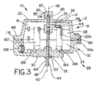
閉鎖近接スイッチ組立体は、内部容積を形成するために結合された、頂部エンクロージャおよび底部エンクロージャを含む。軸突起は頂部エンクロージャの頂面から上方に延び、閉鎖容積を有する内部孔部は、内部容積の一部を形成するために軸突起内に画定される。垂直軸の第1の端部は、軸が頂部エンクロージャおよび底部エンクロージャに対して回転するように、内部孔部の内部に回転可能に配置される。サマリウムコバルト・ターゲット磁石は軸に結合され、該ターゲット磁石は、ターゲット磁石を近接スイッチの頂部の所定の距離内部で回転させるとき、近接スイッチ内部のサマリウムコバルト・ドライバ磁石と相互作用する。該相互作用により、スイッチは第1の状態から第2の状態に、またはその逆に移動する。
【選択図】図3The closed proximity switch assembly includes a top enclosure and a bottom enclosure coupled to form an interior volume. An axial projection extends upward from the top surface of the top enclosure, and an internal bore having a closed volume is defined in the axial projection to form a portion of the internal volume. The first end of the vertical shaft is rotatably disposed within the interior bore such that the shaft rotates relative to the top and bottom enclosures. A samarium cobalt target magnet is coupled to the shaft, and the target magnet interacts with a samarium cobalt driver magnet inside the proximity switch when the target magnet is rotated within a predetermined distance at the top of the proximity switch. The interaction causes the switch to move from the first state to the second state or vice versa.
[Selection] Figure 3
Description
本開示は、一般にエンクロージャに関し、より詳細には、少なくとも1つの磁気近接スイッチによって検出される、少なくとも1つの磁性ターゲットを含む封止エンクロージャに関する。 The present disclosure relates generally to enclosures, and more particularly to sealed enclosures that include at least one magnetic target that is detected by at least one magnetic proximity switch.
磁気近接スイッチは、リミットスイッチとしても公知であり、一般に位置検出のために使用される。通常、磁気近接スイッチ組立体は、ターゲットおよびスイッチング回路を含む近接スイッチを含む。スイッチング回路は、近接スイッチの筐体内に包含される永久磁石により第1の位置に付勢される、レバーなどの要素を含んでもよい。レバーがこの第1の位置にあるとき、近接スイッチは第1の状態に維持され、たとえば、その状態で通常閉じた接点は共通接点と接触する。概して永久磁石を含むターゲットが、近接スイッチの所定の範囲内を通るとき、ターゲット磁石によって生成された磁束により、スイッチング回路のレバーがバイアスを第1の状態から第2の状態に変更し、たとえば、その状態で通常開いた接点が共通接点と接触する。 Magnetic proximity switches are also known as limit switches and are generally used for position detection. Typically, a magnetic proximity switch assembly includes a proximity switch that includes a target and a switching circuit. The switching circuit may include an element, such as a lever, that is biased to a first position by a permanent magnet contained within the proximity switch housing. When the lever is in this first position, the proximity switch is maintained in the first state, for example, a normally closed contact in that state contacts the common contact. When a target, generally including a permanent magnet, passes within a predetermined range of the proximity switch, the magnetic flux generated by the target magnet causes the lever of the switching circuit to change the bias from the first state to the second state, for example, In this state, the normally opened contact comes into contact with the common contact.
一部の応用では、1つまたは複数のターゲット磁石および1つまたは複数の近接スイッチは、近接スイッチを損傷から保護するために封止エンクロージャ内部に配置されてもよい。この構成は、一般に磁気近接スイッチ組立体が、核応用などの危険な環境に使用される場合である。こうした応用では、エンクロージャは、核施設で格納容器の事故またはLOCA(loss of coolant accident(冷却材流出事故))中に起きる高温および圧力に耐えることが意図される。通常、エンクロージャ内部に垂直に配置された軸は、ターゲット磁石が固定近接スイッチに対して軸とともに回転する際に、ターゲット磁石を支持する。通常、軸の頂部は、エンクロージャの頂部を通って延在する頂部開口部内部に配置された封止頂部軸受組立体に結合され、軸の底部は、エンクロージャの底部を通って延在する底部開口部内に受領される。底部開口部を通って延在する軸の底部は、通常、核応用のために使用される制御弁の回転ステムなどの弁要素に結合され、ステムの回転は、エンクロージャ内部に配置された近接スイッチの所定の範囲内でターゲット磁石を回転させる弁で検出されることが可能であり、それによって制御弁が特定の位置にあることが示される。別法として、制御弁の回転ステムは、ターゲット磁石を近接スイッチの所定の範囲外に移動させてもよく、それによって制御弁が特定の位置から移動したことが示される。 In some applications, one or more target magnets and one or more proximity switches may be placed inside a sealed enclosure to protect the proximity switches from damage. This configuration is generally the case when the magnetic proximity switch assembly is used in hazardous environments such as nuclear applications. In such applications, the enclosure is intended to withstand the high temperatures and pressures that occur during containment accidents or LOCA (Loss of Coolant Accidents) in nuclear facilities. Typically, a shaft disposed vertically within the enclosure supports the target magnet as the target magnet rotates with the shaft relative to the fixed proximity switch. Typically, the top of the shaft is coupled to a sealed top bearing assembly disposed within a top opening that extends through the top of the enclosure, and the bottom of the shaft is a bottom opening that extends through the bottom of the enclosure. Received in the department. The bottom of the shaft extending through the bottom opening is typically coupled to a valve element, such as a rotating stem of a control valve used for nuclear applications, and the rotation of the stem is a proximity switch located inside the enclosure Can be detected with a valve that rotates the target magnet within a predetermined range, thereby indicating that the control valve is in a particular position. Alternatively, the rotating stem of the control valve may move the target magnet outside a predetermined range of the proximity switch, thereby indicating that the control valve has moved from a particular position.
磁気近接スイッチ組立体が使用される危険な環境に起因して、エンクロージャは、高圧下での高温気体または他の汚染物質がエンクロージャの中に入ることができないように封止されなければならない。 Due to the hazardous environment in which the magnetic proximity switch assembly is used, the enclosure must be sealed so that hot gases or other contaminants under high pressure cannot enter the enclosure.
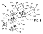
本発明の一例示的態様によれば、閉鎖近接スイッチ組立体は、ベース壁、およびベース壁から下方に延びる複数の側壁を有する頂部エンクロージャを含み、ベース壁および複数の側壁は第1の容積を少なくとも部分的に画定してもよい。軸突起はベース壁の頂面から上方に延びてもよく、内部孔部は、内部孔部が第1の容積の一部を形成するように、軸突起内部に画定されてもよい。内部孔部は閉鎖容積を画定してもよい。また近接スイッチ組立体は、ベース壁およびベース壁から上方に延びる複数の側壁を有する底部エンクロージャを含み、ベース壁および複数の側壁は、第2の容積を少なくとも部分的に画定する。軸開口部はベース壁内に画定されてもよく、軸開口部はベース壁を通って延在してもよい。頂部エンクロージャは、第1の容積および第2の容積が内部容積を画定するために協働するように、底部エンクロージャに結合されてもよい。そのように構成されると、軸開口部の長軸は、内部孔部の長軸と位置合わせされてもよい。また近接スイッチ組立体は、第1の端部、第1の端部と反対側の第2の端部、および第1の端部と第2の端部との間の第1の中間部を有する軸を含み、軸の第1の端部は、頂部エンクロージャの軸突起内に形成された内部孔部の内部に配置される。軸の第1の中間部は、底部エンクロージャ内に形成された軸開口部を通って延在してもよく、軸の第2の端部は、内部容積の外部に配置されてもよい。軸は、頂部エンクロージャおよび底部エンクロージャに対して回転可能である。加えて、近接スイッチ組立体は、軸の第2の中間部に回転不能に結合されたターゲット支持部を含み、第2の中間部は、軸の第1の中間部と第1の端部との間に配置される。ターゲット支持部は軸から離れて延在する半径方向部を含み、ターゲット磁石58は、ターゲット支持部の半径方向部に結合されてもよい。図3および8〜11Bに示されたように、近接スイッチ組立体は、内部容積の内部に配置され、軸が第1の軸位置内にあるとき、ターゲット磁石が少なくとも1つの近接スイッチの頂部からある距離を隔てて配置され、それによって近接スイッチが第1の状態になるように、底部エンクロージャに結合された、少なくとも1つの近接スイッチを含む。軸が第2の軸位置の中に回転されるとき、ターゲット磁石は、少なくとも1つの近接スイッチの頂部に隣接して配置され、それによって近接スイッチが第2の状態になる。第1の状態および第2の状態のそれぞれは、軸の第2の端部に結合された弁要素の一部に対応してもよい。
In accordance with an exemplary aspect of the present invention, a closed proximity switch assembly includes a base wall and a top enclosure having a plurality of sidewalls extending downwardly from the base wall, the base wall and the plurality of sidewalls having a first volume. It may be at least partially defined. The axial protrusion may extend upward from the top surface of the base wall, and the internal hole may be defined within the axial protrusion such that the internal hole forms part of the first volume. The internal bore may define a closed volume. The proximity switch assembly also includes a bottom enclosure having a base wall and a plurality of sidewalls extending upwardly from the base wall, the base wall and the plurality of sidewalls at least partially defining a second volume. The axial opening may be defined in the base wall and the axial opening may extend through the base wall. The top enclosure may be coupled to the bottom enclosure such that the first volume and the second volume cooperate to define an internal volume. When configured as such, the long axis of the shaft opening may be aligned with the long axis of the internal hole. The proximity switch assembly also includes a first end, a second end opposite the first end, and a first intermediate portion between the first end and the second end. A first end of the shaft is disposed within an interior bore formed in the shaft projection of the top enclosure. The first intermediate portion of the shaft may extend through a shaft opening formed in the bottom enclosure, and the second end of the shaft may be located outside the internal volume. The shaft is rotatable with respect to the top and bottom enclosures. In addition, the proximity switch assembly includes a target support that is non-rotatably coupled to the second intermediate portion of the shaft, the second intermediate portion including a first intermediate portion and a first end portion of the shaft. It is arranged between. The target support includes a radial portion extending away from the axis, and the
図3に示されたように、閉鎖近接スイッチ組立体10は、ベース壁14およびベース壁14から下方に延びる複数の側壁16を有する頂部エンクロージャ12を含み、ベース壁14および複数の側壁16は、第1の容積18を少なくとも部分的に画定してもよい。軸突起20はベース壁14の頂面22から上方に延びてもよく、内部孔部24は、内部孔部24が第1の容積18の一部を形成するように、軸突起20内部に画定されてもよい。内部孔部24は閉鎖容積を画定してもよい。また近接スイッチ組立体10は、ベース壁30およびベース壁30から上方に延びる複数の側壁32を有する底部エンクロージャ28を含み、ベース壁30および複数の側壁32は、第2の容積34を少なくとも部分的に画定する。軸開口部36はベース壁30内に画定されてもよく、軸開口部36はベース壁30を通って延在してもよい。頂部エンクロージャ12は、第1の容積18および第2の容積34が内部容積38を画定するために協働するように、底部エンクロージャ28に結合されてもよい。そのように構成されて、軸開口部36の長軸40は内部孔部24の長軸42と位置合わせされてもよい。また近接スイッチ組立体10は、第1の端部46、第1の端部46と反対側の第2の端部48、および第1の端部46と第2の端部48との間の第1の中間部50を含み、軸の第1の端部46は、頂部エンクロージャ12の軸突起20内に形成された内部孔部24の内部に配置される。軸44の第1の中間部50は、底部エンクロージャ内に形成された軸開口部36を通って延在してもよく、軸の第2の端部は、内部容積38の外部に配置されてもよい。軸44は、頂部エンクロージャ12および底部エンクロージャ28に対して回転可能である。加えて、近接スイッチ組立体10は、軸44の第2の中間部54に回転不能に結合されたターゲット支持部52を含み、第2の中間部54は、軸44の第1の中間部50と第1の端部46との間に配置される。ターゲット支持部52は、軸から離れて延在する半径方向部56を含み、ターゲット磁石58は、ターゲット支持部52の半径方向部56に結合されてもよい。図3および8〜11Bに示されたように、近接スイッチ組立体10は、内部容積38の内部に配置され、軸44が第1の軸位置61内にあるとき、ターゲット磁石58が少なくとも1つの近接スイッチ60の頂部64からある距離を隔てて配置され、それによって近接スイッチ60が第1の状態66になるように、底部エンクロージャ28に結合された、少なくとも1つの近接スイッチ60を含む。軸44が第2の軸位置63の中に回転されるとき、ターゲット磁石58は、少なくとも1つの近接スイッチ60の頂部64に隣接して配置され、それによって近接スイッチが第2の状態70になる。第1の状態66および第2の状態70のそれぞれは、軸44の第2の端部48に結合された弁要素の一部に対応してもよい。
As shown in FIG. 3, the closed proximity switch assembly 10 includes a
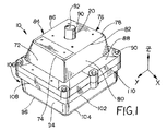
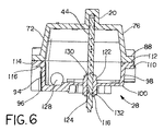
図1、2、3、および6に示されたように、閉鎖近接スイッチ組立体10は、ベース壁14を含み得る頂部エンクロージャ12を含んでもよい。頂部エンクロージャ12のベース壁14は長方形状でもよく、実質的に平面であってもよく、ベース壁14によって形成された平面は実質的に水平であってもよい。本明細書に使用される場合、用語「水平」は、図1に示された基準座標系のXY平面と実質的に同一平面上にある、または実質的に平行である方向を示す。用語「垂直」は、図1に示された基準座標系のXY平面に実質的に垂直である方向(すなわち、Z軸の方向)を示す。ベース壁14に水平に配置される代わりに、平面ベース壁14は、XY平面に対して斜めに配置されてもよい。加えて、図1に示された平面構成よりむしろ、ベース壁14は特定用途に適切なあらゆる形状を有してもよい。たとえば、ベース壁14は湾曲した断面形状を有してもよく、あるいは丸みを帯びた形状であってもよく、またはベース壁14は部分的に湾曲し/丸みを帯び、部分的に平面であってもよい。加えて、ベース壁14は、階段状表面を形成するために垂直にずれた(図示せず)2つ以上の平面部を含んでもよい。
As shown in FIGS. 1, 2, 3, and 6, the closed proximity switch assembly 10 may include a
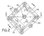
図1、2、3、および6を再度参照すると、頂部エンクロージャ12は、ベース壁14から下方に延びる複数の側壁16を含んでもよい。より具体的には、複数の下方に延びる側壁16は、ベース壁14の第1の外周縁部74から延びる第1の壁72を含んでもよい。第2の壁76は、ベース壁14の第2の外周縁部78から延びてもよく、第2の外周縁部78は、第1の外周縁部74から反対側に配置されてもよい。第3の壁80は、ベース壁14の第3の外周縁部82から延びてもよく、第3の外周縁部82は、第1の外周縁部74と第2の外周縁部78との間に延在してもよい。第4の壁84は、第3の外周縁部82と反対側にあるベース壁14の第4の外周縁部86から延びてもよく、第4の外周縁部86は、第1の外周縁部74と第2の外周縁部78との間に延在してもよい。複数の側壁16のそれぞれは、図1、2、3、および6に示されたように、ベース壁14から斜めに延びてもよい。しかし、任意のまたはすべての複数の側壁16は、ベース壁14から離れてあらゆる適切な手法で、または方向に、たとえば垂直に延びてもよい。複数の側壁16のそれぞれは図1〜3に平面として示されているが、任意のまたはすべての複数の側壁16は、丸みを帯びた、または部分的に平面もしくは部分的に丸みを帯びたなどの、あらゆる適切な形状を有してもよい。さらに、複数の側壁16は、図1、2、3、および6に示されたより多い(または少ない)壁を含んでもよい。上部フランジ88は、複数の側壁16のそれぞれの底部から水平に延びてもよく、上部フランジ88は、その中に配置された複数の嵌合開口部90aを有してもよく、嵌合開口部90aは、頂部エンクロージャ12を底部エンクロージャ28に結合させるボルトを受領するように適合される。構成されたように、ベース壁14および複数の下方に延びる側壁16は、第1の容積18を少なくとも部分的に画定してもよい。
Referring again to FIGS. 1, 2, 3, and 6, the
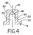
図1、3、4、および6に示されたように、頂部エンクロージャ12は、ベース壁14の頂面22から上方に延びる軸突起20を含んでもよい。軸突起20は、外表面90を含んでもよく、外表面90は、あらゆる適切な形状または形状の組合せを有してもよい。たとえば、外表面90は、外表面90が円筒形であるように、円形断面形状を有してもよい。別法として、外表面90は、たとえば、長円形または多角形の断面形状を有してもよい。また軸突起20は頂面92を有してもよく、頂面92は平面でもよい。しかし、頂部92は、たとえば、円錐形状もしくは半球形状などのあらゆる適切な形状または形状の組合せを有してもよい。内側側面94は、軸突起20の内部孔部24を部分的に画定してもよく、内部孔部24は、軸44が頂部エンクロージャ12に対して回転できる手法で、軸44の第1の端部46を受領するように適合されてもよい。内側側面94は、あらゆる適切な形状または形状の組合せを有してもよい。たとえば、内側側面94は、内側側面94が円筒形であるように、円形断面形状を有してもよい。円筒形の内側側面94は、長軸42を有してもよく、円筒形の内側側面94は、軸44の第1の端部46を受領するようにサイズ化されてもよい。軸突起20の内部孔部24は、さらに内側頂面96によって画定されてもよく、内側頂面96は、あらゆる適切な形状または形状の組合せを有してもよい。たとえば、内側頂面96は、円錐形、平面、または半球形であってもよい。構成されたように、内側側面94および内側頂面96は、第1の容積18の一部を形成する軸突起20内部の閉鎖容積(すなわち、内部孔部24)を少なくとも部分的に画定するように協働する。内部孔部24は、頂部エンクロージャ12の外部と流体連通しない閉鎖容積であるので、内部孔部24は、内部孔部24と頂部エンクロージャ12の外部との間に潜在的なリークパスを提供することなく、軸44の第1の端部46を受領するように適合されたブラインド孔を形成する。
As shown in FIGS. 1, 3, 4, and 6, the
図1、3、および6に示されたように、閉鎖近接スイッチ組立体10はまた、ベース壁30を含み得る底部エンクロージャ28を含んでもよい。底部エンクロージャ28のベース壁30は長方形状でもよく、かつ実質的に平面でもよく、ベース壁30によって形成された平面は、実質的に水平で頂部エンクロージャ12のベース壁14に平行であってもよい。ベース壁30に水平に配置される代わりに、平面ベース壁30は図1に示されたXY基準面に対して斜めに配置されてもよい。加えて、図1に示された平面構造より、むしろベース壁30は、特定用途に適したあらゆる形状を有してもよい。たとえば、ベース壁30は、湾曲した断面形状を有してもよく、あるいは丸みを帯びた形状であってもよく、またはベース壁30は部分的に湾曲し/丸みを帯び、部分的に平面であってもよい。加えて、ベース壁30は、階段状表面を形成するために垂直にずれた(図示せず)2つ以上の平面部を含んでもよい。
As shown in FIGS. 1, 3, and 6, the closed proximity switch assembly 10 may also include a
図1、3、および6を再度参照すると、底部エンクロージャ28は、ベース壁30から上方に延びる複数の側壁32を含んでもよい。より具体的には、複数の上方に延びる側壁32は、ベース壁30の第1の外周縁部96から延びる第1の壁94を含んでもよい。第2の壁98は、ベース壁30の第2の外周縁部100から延びてもよく、第2の外周縁部100は、第1の外周縁部96から反対側に配置されてもよい。第3の壁102は、ベース壁30の第3の外周縁部104から延びてもよく、第3の外周縁部104は、第1の外周縁部96と第2の外周縁部100との間に延在してもよい。第4の壁106は、第3の外周縁部104と反対側にあるベース壁30の第4の外周縁部108から延びてもよく、第4の外周縁部108は、第1の外周縁部96と第2の外周縁部100との間に延在してもよい。複数の側壁32のそれぞれは、図1、3、および6に示されたように、ベース壁30から斜めに離れて延びてもよい。しかし、任意のまたはすべての複数の側壁32は、ベース壁30から離れてあらゆる適切な手法で、または方向に、たとえば垂直に延びてもよい。複数の側壁32のそれぞれは図1、3、および6に平面として示されているが、任意のまたはすべての複数の側壁32は、丸みを帯びた、または部分的に平面もしくは部分的に丸みを帯びたなどの、あらゆる適切な形状を有してもよい。さらに、複数の側壁32は、図1、3、および6に示されたより多い(または少ない)壁を含んでもよい。構成されたように、ベース壁30および複数の下方に延びる側壁32は、第2の容積34を少なくとも部分的に画定してもよい。
Referring again to FIGS. 1, 3, and 6, the
図1、3、および6を再度参照すると、底部エンクロージャ28は、1つまたは複数の側部開口部128を含んでもよく、各側部開口部128はあらゆる適切な場所に形成されてもよい。たとえば、側部開口部128は、第4の壁106を通るような複数の側壁32の1つを通って延在してもよい。側部開口部128は、ねじ山を備えた外面を有する継手が側部開口部128と係合できるように、少なくとも部分的にねじ切られていてもよい内表面によって画定されてもよい。側部開口部128はあらゆる適切な形状を有してもよい。たとえば、側部開口部128は円形断面形状を有してもよい。側部開口部128は、1つまたは複数の近接スイッチ60を外部に配置されたハードウェアに連結させる、複数のワイヤを含むように適合された導管の長さの継手を受領するようにサイズ化されてもよい。
Referring again to FIGS. 1, 3, and 6, the
図1、3、および6を再度参照すると、底部エンクロージャ28は、ベース壁30を通って配置される軸開口部36を含んでもよい。軸開口部38は、軸44の第1の中間部50を受領するようにサイズ化されてもよい。軸開口部36がベース壁30を通って延在するので、第2の容積34は、軸44が軸開口部36を通って配置されない場合、底部エンクロージャ28の外部と流体連通する。軸開口部36は、ベース壁30から上方に延びる、上部ボス部122の内側表面120により部分的に画定されてもよい。加えて、軸開口部36はさらに、ベース壁30から下方に延びる、下部ボス部122の内側表面124により部分的に画定されてもよい。上部ボス部122の内側表面120および下部ボス部122の内側表面124のそれぞれは、軸開口部28が長軸40を有する円筒形の全体形状を有するように、円筒形であってもよい。頂部エンクロージャ12が以下に記載されるように底部エンクロージャに結合される場合、内部孔部24の長軸42は、軸開口部28の長軸40と軸方向に位置合わせされる。
Referring again to FIGS. 1, 3, and 6, the
図1、3、および6を再度参照すると、下部フランジ110は、複数の側壁32のそれぞれの頂部から水平に延びてもよく、下部フランジ110は、上部フランジ88の対応する係合表面114と係合する係合表面112を有してもよい。封止部116は、複数の側壁32のそれぞれの頂部に沿って延在する凹所内に配置されてもよく、封止部116は、頂部エンクロージャ12が底部エンクロージャ28に結合される場合、下部フランジ110の係合表面112と上部フランジ88の係合表面114との間にリークパスが生じないように適合される。封止部116は、放射線耐性の高温シリコーン材料から作成されてもよい。凹所内の封止部116の代わりに、あらゆる封止の配置を使用してもよい。たとえば、下部フランジ110の係合表面112と上部フランジ88の係合表面114との間にガスケットを配置してもよい。
Referring again to FIGS. 1, 3, and 6, the
頂部エンクロージャ12は、底部エンクロージャ28に当技術分野に公知のあらゆる手段で結合されてもよい。たとえば、下部フランジ110は、その中に配置された複数の嵌合開口部90bを有してもよく、嵌合開口部90bは、嵌合開口部90a、90bのそれぞれの対が頂部エンクロージャ12を底部エンクロージャ28に結合させるように適合されたボルト118を受領し得るように、上部フランジ88の嵌合開口部90aと同軸上に位置合わせされる。ボルト118はねじ山を備えた底部を有してもよく、ボルトのねじ山を備えた底部は、嵌合開口部90a、90bの一方または両方のねじ山を備えた内部と係合してもよい。記載されたように組み合わせられると、ベース壁30および複数の下方に延びる側壁32は、第2の容積34を少なくとも部分的に画定してもよく、頂部エンクロージャ12が底部エンクロージャ28に固定される場合、第1の容積18および第2の容積34は内部容積38を形成する。
The
頂部エンクロージャ12および底部エンクロージャ28は、あらゆる適切な材料から製造されてもよい。たとえば、頂部エンクロージャ12および底部エンクロージャ28は、アルミニウムまたは316ステンレス鋼などの、金属または金属合金から形成されてもよい。金属または金属合金エンクロージャ12、28は、鋳造または機械加工などのあらゆるプロセスまたはプロセスの組合せによって形成されてもよい。別法として、頂部エンクロージャ12および底部エンクロージャ28はプラスチックから作成されてもよく、エンクロージャ12、28は射出成形プロセスから形成されてもよい。
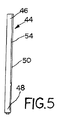
図3、5、および6に示されたように、閉鎖近接スイッチ組立体10はまた、頂部エンクロージャ12および底部エンクロージャ28に対して回転可能な、軸44を含んでもよい。軸は、第1の端部46および第1の端部46と反対側の第2の端部48を有する細長い形状を有してもよい。第1の端部46は円形断面形状を有してもよく、第1の端部46の円形断面形状の直径は、頂部エンクロージャ12の軸突起20の内部孔部24を画定する、内側側面94の円形断面形状の直径よりわずかに小さくてもよい。そのように構成されると、軸の第1の端部46は、閉鎖内部孔部24内部に回転可能に配置される。軸44は、軸44の第1の端部46と第2の端部48との間に配置された第1の中間部50を有してもよい。第1の中間部50は円形断面形状を有してもよく、第1の中間部50の円形断面形状の直径は、第1の中間部50が軸開口部28を通って延在し、軸開口部28内部に回転可能に配置されるように、軸開口部28の円形断面形状の直径よりわずかに小さい。そのように構成されると、軸の第2の端部48は、頂部エンクロージャ12および底部エンクロージャ28によって形成された内部容積38の外部に配置される。たとえば、軸44の第2の端部48は、底部エンクロージャ28のベース壁30から下方に突出する、下部ボス部126を超えて延びてもよい。軸44は、あらゆる適切な形状または形状の組合せを有してもよい。たとえば、軸44は、実質的に均一な断面形状を有する、実質的に円筒形状を有してもよい。
As shown in FIGS. 3, 5, and 6, the closed proximity switch assembly 10 may also include a
図3および6に示されたように、軸44は、軸44の第1の中間部50内に形成された溝内に配置された1対のスナップリング130により所望の位置に維持されてもよい。対のスナップリング130の一方は、上部ボス部122の遠位端に隣接してまたは接して配置されてもよく、対のスナップリング130の他方は、下部ボス部126の遠位端に隣接してまたは接して配置されてもよく、それによって底部エンクロージャ28に対して軸44が上方および/または下方にずれることを防止する。Oリングなどの封止部132は、軸44の第1の中間部50の周囲に延在する凹所内に配置されてもよい。封止部132は、軸44の第1の中間部50と内側表面120、124との間にリークパスが生じないために、軸開口部28を画定する内側表面120、124を封止して係合するように適合される。封止部132は、放射線耐性の高温シリコーン材料から作成されてもよい。
As shown in FIGS. 3 and 6,
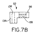
図3、7A、および7Bに示されたように、閉鎖近接スイッチ組立体10はまた、ターゲット支持部52を含んでもよい。ターゲット支持部52は、軸44の第2の中間部54に結合されたベース部134を含んでもよく、第2の中間部54は、軸44の第1の端部46と第1の中間部50との間に配置される。より具体的には、ベース部134は、ベース部134の頂部から底部に延在する開口部136を有してもよく、開口部136は、軸44の第2の中間部54を受領する。ベース部134は、ターゲット支持部52が軸44に沿って回転するように軸44に固定されてもよく、ベース部134を、たとえば、位置決めねじ、キーおよびスロット、または締りばめなどの、当技術分野に公知のあらゆる手段により、軸44に対して回転するのを防止してもよい。加えて、1つまたは複数のスナップリング(図示せず)は、ターゲット支持部52が下部にずれるのを防止するために、ベース部134の底部に隣接した軸44に結合されてもよい。ベース部134は、軸に恒久的に固定されてもよく、またはベース部134は、ベース部134を軸44に対して垂直に再配置できるように、解放可能に固定されてもよい。ベース部134はあらゆる適切な形状または形状の組合せを有する。たとえば、ベース部134は、円形もしくは卵形断面形状を有してもよく、またはベース部134は、正方形もしくは長方形の形状などの、多角形断面形状を有してもよい。ベース部134は、ターゲット支持部52が軸44とともに回転するとき、ベース部134が、1つまたは複数の近接スイッチ60などの内部容積の内部に含まれるいかなる要素にも接触しないように寸法化されてもよい。
As shown in FIGS. 3, 7A, and 7B, the closed proximity switch assembly 10 may also include a
図3、7A、および7Bを再度参照すると、ターゲット支持部52はまた、半径方向部56が軸44から離れて延在するように、ベース部134に結合された半径方向部56を含んでもよい。半径方向部56は、所与の用途に適切なあらゆる形状または形状の組合せを有してもよい。たとえば、半径方向部56は、ベース部134から延びる片持突出部であってもよく、半径方向部56は、長方形断面形状を有してもよい。ターゲット支持部52が使用される2つ以上の半径方向部56を含む場合、各半径方向部は、ベース部134から延びる片持突出部であってもよい。各半径方向部56はそれを通って延在するターゲット開口部138を含んでもよく、ターゲット開口部138の長軸は実質的に垂直であってもよい。ターゲット開口部138はターゲット磁石58を受領するようにサイズ化されてもよい。ターゲット磁石58は、特定用途に適切なあらゆる形状またはサイズを有してもよい。たとえば、ターゲット磁石58は円筒形状を有してもよく、円筒形の深さは、ターゲット磁石58がターゲット開口部138内部に垂直に調節され得るように、半径方向部56の垂直高さより小さくてもよい。ターゲット磁石58は、接着剤により、または磁力によるなどの、当技術分野に公知のあらゆる手段により、ターゲット開口部138内部に固定されてもよい。加えて、ターゲット開口部138は、ターゲット磁石58を担持するために、低減された厚さの底部を有するブラインド孔であってもよい。ターゲット開口部138およびその中に配置されたターゲット磁石58は、半径方向部56上のあらゆる適切な場所に配置されてもよい。たとえば、ターゲット開口部138は、半径方向部56が近接スイッチ60の上の位置まで回転するとき、ターゲット磁石58の少なくとも一部が、近接スイッチ60の頂部64の上または近接スイッチ60の頂部に隣接して配置されるように、半径方向部56上に配置されてもよい。しかし、ターゲット開口部138は、ターゲット磁石58を以下により詳細に記載される手法で近接スイッチ60によって検出できる、半径方向部56上のあらゆる場所に配置されてもよい。ターゲット磁石58は、サマリウムコバルト磁石などの特定用途に適切なあらゆるタイプの磁石であってよい。
Referring again to FIGS. 3, 7A, and 7B, the
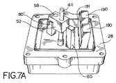
図3、7A、8、および9に示されたように、閉鎖近接スイッチ組立体10はまた、底部エンクロージャ28に結合された1つまたは複数の近接スイッチ60を含んでもよい。近接スイッチ60は、所与の用途に対してあらゆる適切な形状を有する筐体140を含んでもよい。たとえば、筐体140は、第1の平面側壁142および第1の側壁142に平行で、第1の側壁142からずれている第2の平面側壁144を含んでもよい。第3の平面側壁146は、第1の側壁142と、第1の側壁142の第1の外側縁に沿った第2の側壁144との間に垂直に延在してもよく、第4の平面側壁148は、第1の側壁142と、第1の側壁142の第2の外側縁に沿った第2の側壁144との間に垂直に延在してもよい。平面端壁148は、第1の側壁142、第2の側壁144、第3の側壁146、および第4の側壁148に垂直に交差してもよく、平面端壁148は、近接スイッチ60の頂部64を含んでもよい。開口端150は、筐体140の内部容積152にアクセスを提供してもよい。1対の取付フランジ154a、154bは、開口端150に隣接した筐体140に固定されても、または筐体140と一体形成されてもよく、取付フランジ154a、154bは、それぞれが近接スイッチ60の筐体140を、底部エンクロージャ28の適切な部分に固定するボルトを受領するように適合された開口部を有してもよい。
As shown in FIGS. 3, 7A, 8, and 9, the closed proximity switch assembly 10 may also include one or more proximity switches 60 coupled to the bottom enclosure.
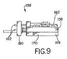
図8および9を参照すると、近接スイッチ60は、筐体140の内部容積152の内部に配置されたスイッチ組立体156を含んでもよい。スイッチ組立体はベース158を含んでもよく、該ベースはベースの第1の部分上に形成された支点160を含んでもよい。レバー162は、ヒンジピン164により支点160に枢動可能に結合されてもよい。ドライバ磁石166は、ベース156内に形成された空洞168内部に配置されてもよく、ドライバ磁石166は、実質的に長方形の断面形状を有してもよい。ドライバ磁石166は、ドライバ磁石166の長軸がベース156の長軸に平行であるように、細長いドライバ磁石166を空洞168の中に受領できるように、空洞168の高さ、幅、および奥行に厳密に対応する高さ、幅、および奥行を有してもよい。唇部170は、ドライバ磁石166を空洞168内部の所望の位置に維持するために、1対の対向して配置された外側縁に沿って延在してもよい。そのように構成されると、ドライバ磁石の長軸は、レバー162がヒンジピン164を中心に釣り合うとき、該レバーの長軸に平行であってもよい。ドライバ磁石166は、あらゆる適切な磁石材料または材料の組合せから作成されてもよい。たとえば、ドライバ磁石166はサマリウムコバルト磁石であってもよい。
With reference to FIGS. 8 and 9, the
またスイッチ組立体156は、端部キャップ180を通って外方に延在する複数のピン182を有する、端部キャップ180を含んでもよい。各ピン182は、以下により詳細に記載される手法で、スイッチ組立体156内で接触するために電気的に接続されてもよい。端部キャップ180は、スイッチ組立体156が筐体140内部に配置されている場合、複数のピン182のそれぞれが筐体140の長軸に実質的に平行であり、複数のピン182のそれぞれの遠位部が筐体140の開口端150の外に突出するように、ベース156の端部に固定されてもよい。また端部キャップ180は、端部キャップ180に堅固に結合され、筐体の長軸に平行に延在する、取付軸184を含んでもよい。
The
図8に示されたように、近接スイッチ60はまた、筐体140の内部容積152の内部に配置された遮蔽172を含んでもよい。遮蔽172は、第1の壁174、およびそれぞれが第1の壁174の対向する外側縁から延びる1対の平行な外側壁176、178を含んでもよく、その結果、壁174、176、178は、筐体140の内部容積152の内部にスイッチ組立体156を受領し、保護するためのチャネルを画定する。
As shown in FIG. 8, the
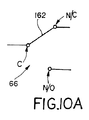
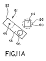
近接スイッチ60のスイッチ組立体156は、フォームCドライ接点などのドライ接点(すなわち、初めに電源に接続されない接点)を含んでもよい。たとえば、図11Aに示されたように、軸44が、その位置でターゲット磁石58が近接スイッチ60の頂部64の(破線領域196によって示された)所定の範囲の外側である第1の軸位置61内にあるとき、ドライバ磁石166は、その位置でレバー162が「通常閉じている」接点N/Cを共通接点C(図10Aに概略的に示されている)と電気的に結合する第1の位置において、レバー162を維持するのに適切な強度のレバー162(またはレバー162に結合された要素)上に磁力をもたらしてもよい。この場合、通常閉じている接点N/Cおよび共通接点Cのそれぞれは、端部キャップ180を通って延在する対応するピン182に電気的に結合されている。共通接点Cが通常閉じている接点N/Cに電気的に結合されているとき、近接スイッチ60は、第1の状態66である。
The
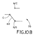
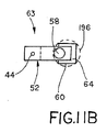
軸44は、第1の軸位置61から図11Bに示された第2の軸位置63に回転されてもよく、第2の軸位置63ではターゲット磁石58は、近接スイッチ60の頂部64の所定の範囲196内部にある。この第2の軸位置63において、レバー162(またはレバーに結合された要素)とターゲット磁石58との間の磁力は、レバー162(またはレバーに結合された要素)とドライバ磁石166との間の磁力より強くなる。ターゲット磁石58とレバー162(またはレバーに結合された要素)との間の力がより強くなることによって、レバー162がヒンジピン164を中心に第1の位置から、レバー162が「通常開いている」接点N/Oを共通接点Cと電気的に結合する第2の位置(図10に概略的に示されている)に枢動する。この場合、通常開いている接点N/Oは、端部キャップ180を通って延在する対応するピン182に電気的に結合されている。レバー162は第2の位置にある状態で、近接スイッチ60は第2の状態70にある。近接スイッチ60は、ターゲット磁石58が頂部64の所定の範囲内にある限り、第2の状態70に維持されてもよい。しかし、ターゲット磁石58が所定の範囲の外側に移動する場合は、近接スイッチ60は、バイアスを第2の状態70から第1の状態66に変更する。
The
上述のように、近接スイッチ60は、ターゲット磁石58が近接スイッチ60の頂部64の所定の範囲196内部にあるときは、バイアスを第1の状態66から第2の状態70に変更する。所定の範囲196は、ドライバ磁石166によって生成された磁場のサイズによって画定されてもよく、ターゲット磁石58は、ターゲット磁石58によって生成された磁場のあらゆる部分が、ドライバ磁石166によって生成された磁場のあらゆる部分と交差するとき、所定の範囲196内部にあってもよい。同様に、ターゲット磁石58は、ターゲット磁石58によって生成された磁場のいかなる部分も、ドライバ磁石166によって生成された磁場の一部と交差しないとき、所定の範囲196の外側にあってよい。所定の範囲196は様々なサイズおよび形状を有することができ、数個の要因は、たとえば、ドライバ磁石166ならびにターゲット磁石58の相対サイズ、厚さ、および/または強度などの、所定の範囲196のサイズおよび形状、ならびにドライバ磁石166およびターゲット磁石58を分離する垂直距離に寄与してもよいことを、当業者は理解するはずである。1つまたは複数のこれらの変数を変えることによって、所定の範囲196のサイズを所望のサイズに調節してもよい。たとえば、ターゲット磁石58は、ターゲット支持部52の上の点から軸44の長軸に沿って見た場合、ターゲット磁石58のあらゆる部分が近接スイッチ60の頂部64のあらゆる部分と交差するとき、所定の範囲196の内部にあってもよい。また、上述された単極双投構成の代わりに、たとえば双極双投構成などの他の構成も可能であることも、当業者は理解するはずである。
As described above, the
上に簡単に説明されたように、ドライバ磁石166およびターゲット磁石58の両方とも、サマリウムコバルト磁石であってもよい。サマリウムコバルト磁石は、従来の磁石に比べて面積比に対する比較的大きい強度を供給する。このような面積比に対する高い強度は、近接スイッチが上述のようにバイアスを変更する際に、接触圧を増加させ、ポジティブスナップをより多くするのを達成するのに役立つ。
As briefly described above, both the
近接スイッチ60は、あらゆる適切な手法で底部エンクロージャ28に結合されてもよい。たとえば、図3に示されたように、平面支持板186は、底部エンクロージャ28のベース壁30上に配置されてもよく、支持板186は、接着剤の使用または機械的結合によるなどの、当技術分野で公知のあらゆる手法によりベース壁30に結合されてもよい。支持板186は、取付軸184、および近接スイッチ60の筐体140を支持板186に固定するために、取付フランジ154a、154bの開口部を通って延在するボルトを受領するように適合された、予め形成された開口部188を有してもよい。開口部188は、たとえば、ターゲット磁石58を近接スイッチ60の頂部64に隣接して配置できる場所などの、支持板186内のあらゆる望ましい場所に配置されてもよい。
先に説明されたように、閉鎖近接スイッチ組立体10は、2つ以上の近接スイッチ60を含んでもよい。たとえば、図3に示されたように、第2の近接スイッチ60’も支持板186に取り付けられてもよく、第2の近接スイッチ60’は、上述の第1の近接スイッチ60と同一であってもよい。第2の近接スイッチ60’は、底部エンクロージャ28の支持板186(またはあらゆる他の部分)上のあらゆる所望の場所に配置されてもよい。たとえば、第1の近接スイッチ60は、筐体140の長軸が軸44の長軸と平行であり、筐体140の長軸が軸44の長軸から第1の距離だけずれるように配置されてもよい。第2の近接スイッチ60’は、筐体140’の長軸が軸44の長軸と平行であり、筐体140の長軸が軸44の長軸から実質的に第1の距離に等しい距離だけずれるように配置されてもよい。第1の近接スイッチ60および第2の近接スイッチ60’は、水平基準線が、軸44、第1の近接スイッチ60、および第2の近接スイッチ60’の長軸を通過し得るように、軸44を中心に対称に配置されてもよい。該別の方法では、軸44の長軸に沿って見た場合、軸44の長軸から第1の近接スイッチ60の長軸に延在する第1の水平線部分と、軸44の長軸から第2の近接スイッチ60’の長軸に延在する第2の水平線部分との間の角度は約180°である。
As previously described, the closed proximity switch assembly 10 may include more than one
3つの近接スイッチが使用される場合、3つの近接スイッチも軸44を中心に対称に配置されてもよい。たとえば、軸44の長軸から第1の近接スイッチ60の長軸に延在する第1の水平線部分と、軸44の長軸から第2の近接スイッチ60’の長軸に延在する第2の水平線部分との間の角度は約120°である。加えて、軸44の長軸から第2の近接スイッチ60’の長軸に延在する第2の水平線部分と、軸44の長軸から第3の近接スイッチ60’’の長軸に延在する第3の水平線部分との間の角度は約120°である。
If three proximity switches are used, the three proximity switches may also be arranged symmetrically about the
図7Aに示されたように、閉鎖近接スイッチ組立体10は、1つまたは複数の端子板190を含んでもよい。1つまたは複数の端子板190は、1つまたは複数の端子板190が、軸44を中心とするターゲット支持部52の回転を妨げないように、支持板186にあらゆる適切な場所で結合されてもよい。1つまたは複数の端子板190は、支持板186に直接結合されてもよく、または支持板186もしくは直立ブラケット191などの底部エンクロージャ28のあらゆる部分に固定された、結合要素に結合されてもよい。端子板190は、取付ファスナが通過し得る、管形状スタンドオフを使用するセラミック絶縁体ベースを有してもよい。この構造は、取付面と端子板190との間に空隙を提供し、それによって端子板190と取付面との間の熱伝導を低減する。
As shown in FIG. 7A, the closed proximity switch assembly 10 may include one or more
各端子板190は、近接スイッチ60のあらゆる複数のピン182に電気的に結合された1つまたは複数のワイヤ(図示せず)をそれぞれが受領するように適合されてもよい。また端子板190は、底部エンクロージャ28の側部開口部128を通って延在し得る1つまたは複数のワイヤを受領するように適合されてもよく、側部開口部128を通って延在するこれらのワイヤは、制御装置または診断装置などの1つまたは複数の外部装置に接続されるように適合されてもよい。端子板190は、近接スイッチ60のピン182に結合されたワイヤの1つを、当技術分野に公知の手法で側部開口部128を通って延在するワイヤに電気的に結合するように作動する。上述の構造の代わりに、または上述の構造に加えて、あらゆる構造または組合せまたはワイヤは、端子板190を通って相互接続されてもよい。たとえば、電力を提供するワイヤは、近接スイッチ60のピン182に電気的に結合されたワイヤに相互接続されてもよい。あらゆる適切な端子板190は、閉鎖近接スイッチ組立体10内に含まれてもよい。たとえば、端子板190は、放射線耐性の高温端子板であってもよい。このような端子板190は、ライトンまたは同様の材料から作成されてもよい。また端子板190は、腐食に耐性を有するために金属内部構成要素を含んでもよい。送信装置(図示せず)は、1つまたは複数の端子板190に結合されてもよく、このような送信装置は、制御弁の弁要素の位置を決定するために、1つまたは複数の近接スイッチ60の状態を示すために、制御装置などの1つまたは複数の外部装置と無線で通信してもよい。
Each
作動中、閉鎖近接スイッチ組立体10は、核応用のために使用される制御弁の回転ステムなどの、弁要素(図示せず)に結合されてもよい。閉鎖近接スイッチ組立体10は、襟部または他のタイプのアダプタによるなどの、当技術分野に公知のあらゆる手段により弁要素に結合されてもよい。加えて、底部エンクロージャ28は、たとえば、底部エンクロージャ28の底部表面上に配置された開口部194の中に延在するボルトにより、弁の一部に結合されてもよい。閉鎖近接スイッチ組立体10は、弁が第1の位置にあるとき、近接スイッチ60が第1の状態66にあるように、ターゲット磁石58が、近接スイッチ60の頂部64の所定の範囲外にある、第1の軸位置61に軸44があるように校正されてもよい。しかし、弁が第2の位置にあるとき、近接スイッチ60が第2の状態70に移動するように、ターゲット磁石58が近接スイッチ60の頂部64の所定の範囲内にある第2の軸位置63の中に軸44を回転させる。先に説明されたように、近接スイッチ60は、ターゲット磁石58が頂部64の所定の範囲内にある限り、第2の状態70に維持される。ターゲット磁石58が所定の範囲外に移動されると、近接スイッチ60は、バイアスを第2の状態70から第1の状態66に変更する。近接スイッチ60が第2の状態70にあるように、ターゲット磁石58が近接スイッチ60の頂部64の所定の範囲内にある第2の軸位置63に軸44を維持することができ、軸44を第1の軸位置61の中に回転させることができ、それによって、軸44に結合された制御要素が回転される、あるいはずらされると、近接スイッチが第1の状態66に移動されることが、当業者には理解されるはずである。この構成において、図10Aおよび10Bに示された通常開いている接点および通常閉じている接点は役割を交代するはずであることが、当業者には理解されるはずである。
In operation, the closed proximity switch assembly 10 may be coupled to a valve element (not shown), such as a rotating stem of a control valve used for nuclear applications. The closed proximity switch assembly 10 may be coupled to the valve element by any means known in the art, such as by a collar or other type of adapter. In addition, the
追加の近接スイッチ60が使用される場合、ターゲット磁石58(またはターゲット支持部52に結合された追加のターゲット磁石)は、上に説明されたように、追加の近接スイッチ60のバイアスを第1の状態66から第2の状態70に(およびその逆に)変更してもよい。端子板190に連結されたワイヤに接続された制御装置(または他の装置)は、制御弁の弁要素の位置を決定するために、1つまたは複数の近接スイッチ60の状態を示してもよい。
If an
頂部エンクロージャ12または底部エンクロージャ28の外側に配置された磁気インターロックインジケータ(図示せず)などの閉鎖近接スイッチ組立体10に、追加の特徴が組み込まれてもよい。磁気インターロックインジケータは、近接スイッチ60が第1の状態66であるか、または第2の状態70であるかを示してもよい。磁気インターロックインジケータは、頂部エンクロージャ12内のノブを使用する機械加工の棒設計を有してもよく、または磁気インターロックインジケータは、ターゲット磁石の磁気吸引によって駆動された摩擦のない磁気浮揚を含んでもよい。また閉鎖近接スイッチ組立体10は、取り付けられた電磁弁を含んでもよい。
Additional features may be incorporated into the closed proximity switch assembly 10 such as a magnetic interlock indicator (not shown) disposed outside the
上述の閉鎖近接スイッチ組立体10の実施形態は、核応用などの危険な環境に使用するための抑制された環境を提供する。より具体的には、閉鎖近接スイッチ組立体10は、核施設で格納容器の事故またはLOCA(loss of coolant accident(冷却材流出事故))中に起きる高温および圧力に耐えることを意図し、閉鎖近接スイッチ組立体10は、防爆性エンクロージャであってもよい。このレベルの保護は、軸突起20の内部孔部24が頂部エンクロージャ12の外部と流体連通しない閉鎖容積であるので、軸開口部(または他の侵入点)による、頂部エンクロージャ12を通る潜在的なリークパスの排除にある程度起因する。他のリークパスは、封止部116、132などの封止部によって防止され、これらは放射線耐性の高温シリコーン材料から作られてもよい。端子板190から(または1つもしくは複数の近接スイッチ60から直接)延びて底部エンクロージャ28の側部開口部128を通るワイヤは、潜在的なリークパスをさらに防止するために側部開口部に封止して結合され得る、放射線耐性導管(図示せず)によって保護されてもよい。
The embodiments of the closed proximity switch assembly 10 described above provide a constrained environment for use in hazardous environments such as nuclear applications. More specifically, the closure proximity switch assembly 10 is intended to withstand the high temperatures and pressures that occur during containment accidents or LOCA (Loss of Coolant Accident) at nuclear facilities, The switch assembly 10 may be an explosion proof enclosure. This level of protection is a closed volume in which the inner bore 24 of the
また上述の閉鎖近接スイッチ組立体10は、所望の用途のために変化され、それによって構成が修正されるべき際に、組立体全体の置換に関連した費用を削減するために、近接スイッチ60の数および配置が可能なモジュール設計、ならびに他の構成部品を提供する。加えて、核接続箱は、必ずしも閉鎖近接スイッチ組立体10を伴う必要がなく、閉鎖近接スイッチ組立体10は、従来のスイッチエンクロージャより必要な導管が少なく、この両方がさらに費用を削減し、導入に必要な労力が少ないことを当業者は理解するはずである。 The closed proximity switch assembly 10 described above may also be modified for the desired application, thereby reducing the cost associated with replacing the entire assembly when the configuration is to be modified. Provide modular designs that can be numbered and arranged, as well as other components. In addition, the nuclear junction box need not necessarily be accompanied by a closed proximity switch assembly 10, which requires fewer conduits than a conventional switch enclosure, both of which further reduce costs and introduce Those skilled in the art should understand that less effort is required.
様々な実施形態が上に説明されたが、本開示はそれに限定されることを意図しない。さらに変形形態を、本開示の実施形態に対して添付の特許請求の範囲内で行うことができる。 Although various embodiments have been described above, the present disclosure is not intended to be limited thereto. Further modifications may be made to the embodiments of the present disclosure within the scope of the appended claims.
Claims (14)
ベース壁および前記ベース壁から上方に延びる複数の側壁を有する底部エンクロージャであって、前記ベース壁および前記複数の側壁は、第2の容積を少なくとも部分的に画定し、軸開口部は前記ベース壁内に配置され、前記軸開口部は前記ベース壁を通って延在し、前記頂部エンクロージャは、前記第1の容積および前記第2の容積が内部容積を画定するために協働するように、また前記軸開口部の長軸が前記内部孔部の長軸と位置合わせするように、前記底部エンクロージャに結合される、底部エンクロージャと、
第1の端部、前記第1の端部と反対側の第2の端部、および前記第1の端部と前記第2の端部との間の第1の中間部を有する軸であって、前記軸の前記第1の端部は、前記頂部エンクロージャの前記軸突起内に形成された前記内部孔部の内部に配置され、前記軸の前記第1の中間部は、前記底部エンクロージャ内に形成された前記軸開口部を通って延在し、前記軸の前記第2の端部は、前記内部容積の外部に配置され、前記軸は、前記頂部エンクロージャおよび前記底部エンクロージャに対して回転可能である、軸と、
前記軸の第2の中間部に回転不能に結合されたターゲット支持部であって、前記第2の中間部は、前記第1の中間部と前記軸の前記第1の端部との間に配置され、前記ターゲット支持部は、前記軸から離れて延在する半径方向部を含む、ターゲット支持部と、
前記ターゲット支持部の前記半径方向部に結合されたターゲット磁石と、
前記軸が第1の軸位置内にあるとき、前記ターゲット磁石が少なくとも1つの近接スイッチの頂部からある距離を隔てて配置され、それによって前記近接スイッチが第1の状態になるように、また前記軸を第2の軸位置の中で回転させるとき、前記ターゲット磁石は、前記少なくとも1つの近接スイッチの前記頂部に隣接して配置され、それによって前記近接スイッチが第2の状態になるように、前記内部容積の内部に配置され、前記底部エンクロージャに結合された少なくとも1つの近接スイッチであって、前記第1の状態および前記第2の状態のそれぞれは、前記軸の前記第2の端部に結合された弁要素の一部に対応する、少なくとも1つの近接スイッチと、を備える閉鎖近接スイッチ組立体。 A top enclosure having a base wall and a plurality of side walls extending downwardly from the base wall, wherein the base wall and the plurality of side walls at least partially define a first volume, and an axial protrusion is disposed on the base wall; Extending upward from the top surface, an internal hole is defined within the axial projection such that the internal hole forms part of the first volume, and the internal hole defines a closed volume; A top enclosure;
A bottom enclosure having a base wall and a plurality of side walls extending upwardly from the base wall, wherein the base wall and the plurality of side walls at least partially define a second volume, and an axial opening is the base wall Disposed within, the axial opening extends through the base wall, and the top enclosure cooperates such that the first volume and the second volume define an internal volume. A bottom enclosure coupled to the bottom enclosure such that a major axis of the shaft opening is aligned with a major axis of the internal bore;
A shaft having a first end, a second end opposite to the first end, and a first intermediate portion between the first end and the second end. The first end of the shaft is disposed inside the inner hole formed in the shaft projection of the top enclosure, and the first intermediate portion of the shaft is disposed in the bottom enclosure. Extending through the shaft opening formed in the shaft, wherein the second end of the shaft is disposed outside the internal volume, the shaft rotating relative to the top enclosure and the bottom enclosure Possible, axis,
A target support portion non-rotatably coupled to a second intermediate portion of the shaft, wherein the second intermediate portion is between the first intermediate portion and the first end portion of the shaft. Disposed, and the target support includes a radial portion extending away from the axis;
A target magnet coupled to the radial portion of the target support;
When the axis is in a first axis position, the target magnet is arranged at a distance from the top of at least one proximity switch, so that the proximity switch is in a first state, and When rotating an axis in a second axial position, the target magnet is positioned adjacent to the top of the at least one proximity switch, thereby placing the proximity switch in a second state, At least one proximity switch disposed within the internal volume and coupled to the bottom enclosure, wherein each of the first state and the second state is at the second end of the shaft; A closed proximity switch assembly comprising at least one proximity switch corresponding to a portion of the combined valve elements.
Applications Claiming Priority (3)
| Application Number | Priority Date | Filing Date | Title |
|---|---|---|---|
| US201161480342P | 2011-04-28 | 2011-04-28 | |
| US61/480,342 | 2011-04-28 | ||
| PCT/US2012/034919 WO2012148970A1 (en) | 2011-04-28 | 2012-04-25 | Enclosed proximity switch assembly |
Publications (1)
| Publication Number | Publication Date |
|---|---|
| JP2014513402A true JP2014513402A (en) | 2014-05-29 |
Family
ID=46085691
Family Applications (1)
| Application Number | Title | Priority Date | Filing Date |
|---|---|---|---|
| JP2014508497A Pending JP2014513402A (en) | 2011-04-28 | 2012-04-25 | Closed proximity switch assembly |
Country Status (11)
| Country | Link |
|---|---|
| US (1) | US8593241B2 (en) |
| EP (1) | EP2702600B1 (en) |
| JP (1) | JP2014513402A (en) |
| KR (1) | KR101942116B1 (en) |
| CN (2) | CN102760610B (en) |
| AR (1) | AR090016A1 (en) |
| AU (1) | AU2012249869B2 (en) |
| BR (1) | BR112013027679A2 (en) |
| CA (1) | CA2834048A1 (en) |
| RU (1) | RU2013151661A (en) |
| WO (1) | WO2012148970A1 (en) |
Families Citing this family (10)
| Publication number | Priority date | Publication date | Assignee | Title |
|---|---|---|---|---|
| CN102760610B (en) * | 2011-04-28 | 2016-08-31 | 通用设备和制造公司 | The proximity switch assembly of encapsulation |
| CN203367140U (en) * | 2011-12-28 | 2013-12-25 | 通用设备和制造公司 | Object support and housing |
| US20140062579A1 (en) * | 2012-08-29 | 2014-03-06 | Bruce Rigsby | Apparatus for fluid control device monitoring |
| CN103062490B (en) * | 2013-01-25 | 2014-10-22 | 北京通宇泰克科技有限公司 | Angle type magnetic conducting ball valve switch |
| US9355800B2 (en) | 2013-09-13 | 2016-05-31 | Cooper Technologies Company | Magnetic control devices for enclosures |
| US9664536B2 (en) * | 2014-02-14 | 2017-05-30 | General Equipment And Manufacturing Company | Calibration mechanism for proximity switch |
| US10298229B2 (en) * | 2017-01-05 | 2019-05-21 | General Equipment And Manufacturing Company, Inc. | Switch adapter |
| US10666251B2 (en) * | 2018-02-14 | 2020-05-26 | General Equipment And Manufacturing Company, Inc. | Target magnet mechanism for proximity switch |
| CN108766803B (en) * | 2018-08-02 | 2024-10-11 | 上海飞力勋铖电气科技有限公司 | Waterproof travel switch with modularized structure |
| FR3104839B1 (en) * | 2019-12-16 | 2022-06-24 | Legrand France | Equipment including a removable finishing block |
Citations (4)
| Publication number | Priority date | Publication date | Assignee | Title |
|---|---|---|---|---|
| JPS4522457B1 (en) * | 1967-10-06 | 1970-07-29 | ||
| JPS62184722A (en) * | 1986-02-08 | 1987-08-13 | 中根 明夫 | Switch with delay operation function |
| JPH064941A (en) * | 1992-06-18 | 1994-01-14 | Hokuriku Electric Ind Co Ltd | Rotating electric parts |
| JPH0617969A (en) * | 1992-03-20 | 1994-01-25 | Bray Internatl Inc | Valve position monitoring device |
Family Cites Families (9)
| Publication number | Priority date | Publication date | Assignee | Title |
|---|---|---|---|---|
| US2803720A (en) * | 1954-04-20 | 1957-08-20 | Mason Charles Francis | High speed rotary switching apparatus |
| BE570551A (en) * | 1957-08-26 | |||
| DE1515681A1 (en) * | 1965-09-14 | 1969-11-20 | Platte & Co | Electrical snap switch |
| FR2166721A6 (en) * | 1972-01-05 | 1973-08-17 | Rhone Poulenc Sa | |
| US4225837A (en) * | 1978-12-28 | 1980-09-30 | General Equipment & Mfg. Co., Inc. | Armature for a proximity switch |
| US6650211B2 (en) * | 2001-05-25 | 2003-11-18 | Asco Controls, Lp | Valve position switch |
| JP4245190B2 (en) * | 2007-02-26 | 2009-03-25 | 株式会社巴技術研究所 | Valve opening detection device |
| ITBS20070124A1 (en) * | 2007-08-10 | 2009-02-11 | Soldo S R L Socio Unico | SIGNAL ACTUATOR DEVICE FOR SWITCHES AND ITS CONSTRUCTION METHOD |
| CN102760610B (en) * | 2011-04-28 | 2016-08-31 | 通用设备和制造公司 | The proximity switch assembly of encapsulation |
-
2011
- 2011-09-30 CN CN201110305657.5A patent/CN102760610B/en active Active
- 2011-09-30 CN CN2011203833502U patent/CN202259008U/en not_active Withdrawn - After Issue
-
2012
- 2012-04-25 BR BR112013027679A patent/BR112013027679A2/en not_active IP Right Cessation
- 2012-04-25 AU AU2012249869A patent/AU2012249869B2/en not_active Expired - Fee Related
- 2012-04-25 CA CA2834048A patent/CA2834048A1/en active Pending
- 2012-04-25 WO PCT/US2012/034919 patent/WO2012148970A1/en not_active Ceased
- 2012-04-25 EP EP12721376.7A patent/EP2702600B1/en active Active
- 2012-04-25 RU RU2013151661/07A patent/RU2013151661A/en not_active Application Discontinuation
- 2012-04-25 JP JP2014508497A patent/JP2014513402A/en active Pending
- 2012-04-25 KR KR1020137028079A patent/KR101942116B1/en active Active
- 2012-04-25 US US13/456,130 patent/US8593241B2/en active Active
- 2012-04-27 AR ARP120101528A patent/AR090016A1/en unknown
Patent Citations (4)
| Publication number | Priority date | Publication date | Assignee | Title |
|---|---|---|---|---|
| JPS4522457B1 (en) * | 1967-10-06 | 1970-07-29 | ||
| JPS62184722A (en) * | 1986-02-08 | 1987-08-13 | 中根 明夫 | Switch with delay operation function |
| JPH0617969A (en) * | 1992-03-20 | 1994-01-25 | Bray Internatl Inc | Valve position monitoring device |
| JPH064941A (en) * | 1992-06-18 | 1994-01-14 | Hokuriku Electric Ind Co Ltd | Rotating electric parts |
Also Published As
| Publication number | Publication date |
|---|---|
| AR090016A1 (en) | 2014-10-15 |
| KR20140018952A (en) | 2014-02-13 |
| KR101942116B1 (en) | 2019-01-24 |
| CN202259008U (en) | 2012-05-30 |
| AU2012249869B2 (en) | 2016-05-12 |
| EP2702600A1 (en) | 2014-03-05 |
| EP2702600B1 (en) | 2015-03-04 |
| RU2013151661A (en) | 2015-06-10 |
| CN102760610A (en) | 2012-10-31 |
| CA2834048A1 (en) | 2012-11-01 |
| US20130021123A1 (en) | 2013-01-24 |
| CN102760610B (en) | 2016-08-31 |
| US8593241B2 (en) | 2013-11-26 |
| WO2012148970A1 (en) | 2012-11-01 |
| AU2012249869A1 (en) | 2013-11-07 |
| BR112013027679A2 (en) | 2016-12-27 |
Similar Documents
| Publication | Publication Date | Title |
|---|---|---|
| JP2014513402A (en) | Closed proximity switch assembly | |
| US10948319B2 (en) | Electrical process control sensor assemblies | |
| US9202650B2 (en) | Quick disconnect connector assembly | |
| US10003333B2 (en) | Method of manufacturing an enclosed proximity switch assembly | |
| KR101831454B1 (en) | Flameproof motor | |
| KR102452822B1 (en) | switch adapter | |
| JPWO2012133702A1 (en) | Base station apparatus and lid mounting method | |
| CN222637158U (en) | DC contactor shell and DC contactor | |
| RO126891B1 (en) | Explosion-proof switch |
Legal Events
| Date | Code | Title | Description |
|---|---|---|---|
| A621 | Written request for application examination |
Free format text: JAPANESE INTERMEDIATE CODE: A621 Effective date: 20150402 |
|
| A977 | Report on retrieval |
Free format text: JAPANESE INTERMEDIATE CODE: A971007 Effective date: 20160126 |
|
| A131 | Notification of reasons for refusal |
Free format text: JAPANESE INTERMEDIATE CODE: A131 Effective date: 20160202 |
|
| A02 | Decision of refusal |
Free format text: JAPANESE INTERMEDIATE CODE: A02 Effective date: 20160906 |