JP2014512302A - 2-2 or 2-1 hybrid power device for ships - Google Patents
2-2 or 2-1 hybrid power device for ships Download PDFInfo
- Publication number
- JP2014512302A JP2014512302A JP2014503999A JP2014503999A JP2014512302A JP 2014512302 A JP2014512302 A JP 2014512302A JP 2014503999 A JP2014503999 A JP 2014503999A JP 2014503999 A JP2014503999 A JP 2014503999A JP 2014512302 A JP2014512302 A JP 2014512302A
- Authority
- JP
- Japan
- Prior art keywords
- power
- power transmission
- propulsion system
- propulsor
- input
- Prior art date
- Legal status (The legal status is an assumption and is not a legal conclusion. Google has not performed a legal analysis and makes no representation as to the accuracy of the status listed.)
- Pending
Links
Images


Classifications
-
- B—PERFORMING OPERATIONS; TRANSPORTING
- B63—SHIPS OR OTHER WATERBORNE VESSELS; RELATED EQUIPMENT
- B63H—MARINE PROPULSION OR STEERING
- B63H23/00—Transmitting power from propulsion power plant to propulsive elements
- B63H23/02—Transmitting power from propulsion power plant to propulsive elements with mechanical gearing
- B63H23/10—Transmitting power from propulsion power plant to propulsive elements with mechanical gearing for transmitting drive from more than one propulsion power unit
-
- B—PERFORMING OPERATIONS; TRANSPORTING
- B63—SHIPS OR OTHER WATERBORNE VESSELS; RELATED EQUIPMENT
- B63H—MARINE PROPULSION OR STEERING
- B63H21/00—Use of propulsion power plant or units on vessels
- B63H21/20—Use of propulsion power plant or units on vessels the vessels being powered by combinations of different types of propulsion units
-
- B—PERFORMING OPERATIONS; TRANSPORTING
- B63—SHIPS OR OTHER WATERBORNE VESSELS; RELATED EQUIPMENT
- B63H—MARINE PROPULSION OR STEERING
- B63H23/00—Transmitting power from propulsion power plant to propulsive elements
-
- B—PERFORMING OPERATIONS; TRANSPORTING
- B63—SHIPS OR OTHER WATERBORNE VESSELS; RELATED EQUIPMENT
- B63H—MARINE PROPULSION OR STEERING
- B63H21/00—Use of propulsion power plant or units on vessels
- B63H21/20—Use of propulsion power plant or units on vessels the vessels being powered by combinations of different types of propulsion units
- B63H2021/202—Use of propulsion power plant or units on vessels the vessels being powered by combinations of different types of propulsion units of hybrid electric type
- B63H2021/205—Use of propulsion power plant or units on vessels the vessels being powered by combinations of different types of propulsion units of hybrid electric type the second power unit being of the internal combustion engine type, or the like, e.g. a Diesel engine
-
- B—PERFORMING OPERATIONS; TRANSPORTING
- B63—SHIPS OR OTHER WATERBORNE VESSELS; RELATED EQUIPMENT
- B63H—MARINE PROPULSION OR STEERING
- B63H23/00—Transmitting power from propulsion power plant to propulsive elements
- B63H23/02—Transmitting power from propulsion power plant to propulsive elements with mechanical gearing
- B63H23/10—Transmitting power from propulsion power plant to propulsive elements with mechanical gearing for transmitting drive from more than one propulsion power unit
- B63H23/12—Transmitting power from propulsion power plant to propulsive elements with mechanical gearing for transmitting drive from more than one propulsion power unit allowing combined use of the propulsion power units
- B63H23/14—Transmitting power from propulsion power plant to propulsive elements with mechanical gearing for transmitting drive from more than one propulsion power unit allowing combined use of the propulsion power units with unidirectional drive or where reversal is immaterial
-
- B—PERFORMING OPERATIONS; TRANSPORTING
- B63—SHIPS OR OTHER WATERBORNE VESSELS; RELATED EQUIPMENT
- B63H—MARINE PROPULSION OR STEERING
- B63H23/00—Transmitting power from propulsion power plant to propulsive elements
- B63H23/02—Transmitting power from propulsion power plant to propulsive elements with mechanical gearing
- B63H23/10—Transmitting power from propulsion power plant to propulsive elements with mechanical gearing for transmitting drive from more than one propulsion power unit
- B63H23/18—Transmitting power from propulsion power plant to propulsive elements with mechanical gearing for transmitting drive from more than one propulsion power unit for alternative use of the propulsion power units
-
- B—PERFORMING OPERATIONS; TRANSPORTING
- B63—SHIPS OR OTHER WATERBORNE VESSELS; RELATED EQUIPMENT
- B63H—MARINE PROPULSION OR STEERING
- B63H23/00—Transmitting power from propulsion power plant to propulsive elements
- B63H23/30—Transmitting power from propulsion power plant to propulsive elements characterised by use of clutches
-
- B—PERFORMING OPERATIONS; TRANSPORTING
- B63—SHIPS OR OTHER WATERBORNE VESSELS; RELATED EQUIPMENT
- B63H—MARINE PROPULSION OR STEERING
- B63H5/00—Arrangements on vessels of propulsion elements directly acting on water
- B63H5/07—Arrangements on vessels of propulsion elements directly acting on water of propellers
- B63H5/08—Arrangements on vessels of propulsion elements directly acting on water of propellers of more than one propeller
-
- Y—GENERAL TAGGING OF NEW TECHNOLOGICAL DEVELOPMENTS; GENERAL TAGGING OF CROSS-SECTIONAL TECHNOLOGIES SPANNING OVER SEVERAL SECTIONS OF THE IPC; TECHNICAL SUBJECTS COVERED BY FORMER USPC CROSS-REFERENCE ART COLLECTIONS [XRACs] AND DIGESTS
- Y02—TECHNOLOGIES OR APPLICATIONS FOR MITIGATION OR ADAPTATION AGAINST CLIMATE CHANGE
- Y02T—CLIMATE CHANGE MITIGATION TECHNOLOGIES RELATED TO TRANSPORTATION
- Y02T70/00—Maritime or waterways transport
- Y02T70/50—Measures to reduce greenhouse gas emissions related to the propulsion system
- Y02T70/5218—Less carbon-intensive fuels, e.g. natural gas, biofuels
- Y02T70/5236—Renewable or hybrid-electric solutions
Abstract
【課題】少なくとも1つまたは複数の推進デバイスに動力を伝達するためデバイスを提供する。
【解決手段】プロペラを備えるサーフェスドライブのような単一のまたは2つのプロパルサーに、動力、たとえば、トルクを分配する、2つのハイブリッド原動機、すなわち、電気モータおよび内燃機関を有する船舶のためのハイブリッド動力デバイスが提供される。この原動機は、単独でまたは調和して動力を印加することができるが、いずれの場合も実質的に最適な推進効率を維持することができる。原動機の動力出力は、単一のプロパルサーを駆動するために動力出力を剛性することができるギヤボックスのような動力伝達デバイスと連通する、あるいは、2つのプロパルサーを駆動する動力分割実施形態を有することができる。さらに、複数のハイブリッド動力デバイスを他の実施形態に展開することができる。
【選択図】図3A device for transmitting power to at least one or more propulsion devices is provided.
A hybrid for a ship having two hybrid prime movers, namely an electric motor and an internal combustion engine, that distributes power, eg torque, to a single or two propulsers such as a surface drive with a propeller. A power device is provided. This prime mover can apply power alone or in harmony, but in any case can maintain substantially optimum propulsion efficiency. The power output of the prime mover communicates with a power transmission device such as a gearbox that can stiffen the power output to drive a single propulsor, or a power split embodiment that drives two propulsers. Can have. In addition, multiple hybrid power devices can be deployed in other embodiments.
[Selection] Figure 3
Description
本発明は、全般的には船舶用パワートレインに関し、より詳細には、ハイブリッド原動機から、船舶上の1つまたは複数の推進デバイスに動力を伝達するためのデバイスに関する。 The present invention relates generally to marine powertrains, and more particularly to devices for transmitting power from a hybrid prime mover to one or more propulsion devices on a marine vessel.
数多くの環境問題に照らして、主に排気物質および騒音を低減する形態で汚染を低減し、全体的な燃料効率を改善するために、内燃機関にのみ依拠するのではなく、電力を用いて動力供給することができるハイブリッド電気燃焼船舶が使用されている。その結果、そのようなハイブリッド船舶は、ますます普及してきた。現在までのところ、自動車産業において、この傾向の商業例が最も普及していることが分かっている。 In light of a number of environmental issues, power is powered using electricity rather than relying solely on internal combustion engines to reduce pollution and improve overall fuel efficiency, primarily in the form of reduced emissions and noise. Hybrid electric combustion ships that can be supplied are used. As a result, such hybrid ships have become increasingly popular. To date, it has been found that commercial examples of this trend are most prevalent in the automotive industry.
船舶において電力およびハイブリッド駆動技術を利用するために、いくつかの取り組みが行われてきた。ただし、最も普及した船舶における例は、船舶のうち最も大型のもののみにおけるカスタムハイブリッド電気燃焼システム中で実装されているが、これらの船舶のいずれも、推進効率に著しく影響を及ぼすことなしに、電気モータおよび内燃機関のような動力源のうちいずれかまたはそれら両方の制御された適用例を可能にする動力デバイスを組み込むものではない。 Several efforts have been made to utilize power and hybrid drive technology in ships. However, although the most popular ship example is implemented in a custom hybrid electric combustion system on only the largest of the ships, none of these ships has a significant impact on propulsion efficiency, It does not incorporate power devices that allow controlled applications of either or both power sources such as electric motors and internal combustion engines.
現在の船舶用パワートレインでは、騒音、大気汚染、低い燃焼効率および信頼性のような問題に対する解決策を提供することができないので、騒音および排気物質を減少させる形態で環境汚染を少なくし、改善された推進効率および燃焼効率を犠牲にすることなしに速度およびステルスの点で副原動機の利点を実現するグリーンソリューションが望まれてきた。次いで、速度および推進効率に影響を及ぼすことなしに、ユーザが、ある特定の状況では電気モータにのみ依拠し、他の状況では内燃機関にのみ依拠し、あるいは他の状況では両方の原動機に依拠することを可能にする、可撓性で効率的な船舶用のハイブリッド動力デバイスが必要とされる。 Current marine powertrains cannot provide solutions to problems such as noise, air pollution, low combustion efficiency and reliability, thus reducing and improving environmental pollution in a form that reduces noise and emissions There has been a desire for a green solution that realizes the benefits of a secondary prime mover in terms of speed and stealth without sacrificing the propulsion efficiency and combustion efficiency achieved. Then, without affecting the speed and propulsion efficiency, the user relies only on the electric motor in certain situations, only on the internal combustion engine in other situations, or on both prime movers in other situations. There is a need for a flexible and efficient marine hybrid power device that makes it possible to do so.
本発明は、2つのハイブリッド動力源から、サーフェスプロペラドライブ、従来のプロペラ設備、ウォータジェット、船外ドライブ、ポッドドライブなどのような少なくとも1つまたは複数の推進デバイスに動力を伝達するためデバイスを提供する。 The present invention provides a device for transmitting power from two hybrid power sources to at least one or more propulsion devices such as surface propeller drives, conventional propeller equipment, water jets, outboard drives, pod drives, etc. To do.
本発明の一態様によれば、船舶のための推進システムは、動力伝達デバイスと連通する第1の動力伝達エレメントを有する電気モータであって、それにより、第1のトルクが動力伝達デバイスの第1の入力部に伝達される、電気モータを含む。さらに、本システムは、動力伝達デバイスと連通する第2の動力伝達エレメントを有する内燃機関であって、それにより、第2のトルクが動力伝達デバイスの第2の入力部に伝達される、内燃機関を含む。また、動力入力エレメントを有する少なくとも1つのプロパルサーが設けられ、動力入力エレメントに印加されたトルクは、船舶を動かすための推進力を発生させる。動力伝達デバイスは、少なくとも1つのプロパルサーの動力入力エレメントと連通する少なくとも1つの出力部と、1)第1のトルクまたは第2のトルクが所与の時間に印加されたとき、少なくとも1つのプロパルサーの動力入力エレメントと連通する出力部の実質的に対応するトルクが存在し、2)第1の入力部に印加された第1のトルクと第2の入力部に印加された第2のトルクとが実質的に同じ毎分回転数であるとき、少なくとも1つのプロパルサーの動力入力エレメントと連通する出力部の実質的に対応する毎分回転数が生じるように構成された動力伝達アセンブリとをさらに備える。 According to one aspect of the present invention, a propulsion system for a ship is an electric motor having a first power transmission element in communication with a power transmission device, whereby a first torque is applied to the first power transmission device. 1 includes an electric motor transmitted to one input. The system further includes an internal combustion engine having a second power transmission element in communication with the power transmission device, whereby the second torque is transmitted to the second input of the power transmission device. including. Also, at least one propulsor having a power input element is provided, and the torque applied to the power input element generates a propulsive force for moving the ship. The power transmission device includes at least one output in communication with a power input element of at least one propulser, and 1) at least one profile when a first torque or a second torque is applied at a given time. There is a substantially corresponding torque in the output portion in communication with the power input element of the pulsar, and 2) a first torque applied to the first input portion and a second torque applied to the second input portion. And a power transmission assembly configured to produce a substantially corresponding rotational speed of an output portion in communication with a power input element of at least one propulsor when the rotational speeds are substantially the same. Further prepare.
本実施形態の別の態様では、プロパルサースラスターは、実質的に同じ毎分回転数で、第1の入力部に印加された第1のトルクと第2の入力部に印加された第2のトルクとの両方を用いてフルパワーで作動したときに、最適効率となるように構成される。 In another aspect of this embodiment, the propulsor thruster has a first torque applied to the first input and a second applied to the second input at substantially the same number of revolutions per minute. It is configured for optimum efficiency when operating at full power using both torque.
本実施形態の別の態様によれば、RPM均等化デバイスは、第1の入力部および第2の入力部が実質的に同じ毎分回転数で回転するように、電気モータの第1の動力伝達エレメントおよび内燃機関の第2の動力伝達エレメントからの動力伝達を制御するように構成される。 According to another aspect of this embodiment, the RPM equalization device provides the first power of the electric motor such that the first input and the second input rotate at substantially the same number of revolutions per minute. It is configured to control power transmission from the transmission element and the second power transmission element of the internal combustion engine.
本実施形態のさらなる態様では、自動モード選択エレメントは、いずれかの動力源を独立してまたは組み合わせて使用することができるように、電気モータおよび内燃機関からの動力の印加を制御するように構成される。 In a further aspect of this embodiment, the automatic mode selection element is configured to control the application of power from the electric motor and the internal combustion engine so that any power source can be used independently or in combination. Is done.
本発明のさらに別の態様では、内燃機関は、第2の入力部の毎分回転数を電気モータよりも高速にする動力出力を含む動力出力の範囲にわたって作動するように構成され、それにより、内燃機関がブースタとなる。 In yet another aspect of the present invention, the internal combustion engine is configured to operate over a range of power outputs that includes a power output that causes the second input to rotate at a higher speed per minute than the electric motor, thereby The internal combustion engine becomes a booster.
本実施形態の別の態様によれば、動力伝達デバイスは、船舶のトランサムに対して固定されたギヤボックスハウジングをさらに含むギヤボックスである。また、このギヤボックスは、ギヤボックスハウジング内に装着されたギヤトレインを含む動力伝達アセンブリであって、ギヤトレインが、第1の入力部および第2の入力部から動力を受容し、2つの動力伝達デバイスへの動力を実質的に2等分する、動力伝達アセンブリも含む。 According to another aspect of this embodiment, the power transmission device is a gearbox that further includes a gearbox housing secured to the transom of the ship. The gear box is a power transmission assembly including a gear train mounted in a gear box housing, and the gear train receives power from the first input portion and the second input portion and receives two powers. A power transmission assembly is also included that substantially bisects the power to the transmission device.
別の実施形態によれば、船舶を推進する方法は、複数の原動機を動作させることであって、1つの原動機が電気モータであり、1つの原動機が内燃機関である、原動機を動作させることを含む。本方法は、いずれかのまたは両方の原動機によって生成された動力を、ギヤボックスに収容されたギヤトレインの中に受容することと、動力を、1つまたは2つの動力成分のいずれかとして出力することとをさらに含む。次に、本方法は、1つまたは2つの動力成分を、対応する1つまたは2つのクラッチアセンブリの中に受容することと、1つまたは2つの動力成分を、クラッチアセンブリを通して、それに動作可能に接続された対応する1つまたは2つのプロパルサーに選択的に伝達し、それにより、船舶を推進することとを含む。 According to another embodiment, a method for propelling a ship is to operate a plurality of prime movers, where one prime mover is an electric motor and one prime mover is an internal combustion engine. Including. The method receives power generated by either or both prime movers in a gear train housed in a gearbox and outputs the power as either one or two power components. And further. The method then accepts one or two power components into the corresponding one or two clutch assemblies and enables one or two power components to operate through the clutch assembly. Selectively communicating to the corresponding one or two connected propulsers, thereby propelling the vessel.
唯一の原動機として電気モータを使用できるようにすることにより、ボートおよび他の船舶は、航路規制によって定められるように、排気物質による汚染を低減し、マリーナまたはその近くにあるとき、あるいは他の係留場所にあるときの騒音を低減することができるようになる。 By allowing the use of electric motors as the only prime mover, boats and other ships will reduce pollution due to exhaust emissions, as required by navigation regulations, and when moored or near a marina or other mooring Noise when in a place can be reduced.
さらに、様々な管轄区域では、ボートおよび他の船舶について、反アイドリング規則および規制が提案され、実施されていることを留意されたい。いくつかの管轄区域は、これらの管轄区域内の水路のある特定の部分について、内燃機関の使用を禁止する、または内燃機関の最大馬力定格を定める規則および規制を提案し、実施している。 Furthermore, it should be noted that anti-idling rules and regulations have been proposed and implemented for boats and other ships in various jurisdictions. Some jurisdictions have proposed and implemented rules and regulations that prohibit the use of internal combustion engines or establish maximum horsepower ratings for internal combustion engines for certain parts of the waterways within these jurisdictions.
さらに、船舶、特に軍事行動に関わるものは、探知されないように、できる限り静かに作動しなければならないことがある。いわゆるステルスモードにおいて電気モータのみを用いて静かに船舶に動力供給することが可能であることにより、敵部隊による探知を回避するのを助けることができ、したがって、生命および装備を確保することができる。 In addition, ships, especially those involved in military action, may need to operate as quietly as possible so that they are not detected. Being able to quietly power a ship using only an electric motor in so-called stealth mode can help avoid detection by enemy units, thus ensuring life and equipment .
また、船舶は、航跡がない水路の指定部分を横断するときに、航跡が生じないよういするために、より低速で動作するように要求されることがある。重要なことに、電気モータは、内燃機関よりも静かでクリーンであるだけではなく、より低速時に内燃機関よりも燃料効率がよい。 Ships may also be required to operate at lower speeds to avoid wakes when crossing a designated portion of a channel with no wakes. Importantly, electric motors are not only quieter and cleaner than internal combustion engines, but are also more fuel efficient than internal combustion engines at lower speeds.
代替的には、唯一の原動機として内燃機関を使用することが可能であることにより、電気モータの故障時、またはバッテリーが放電したときなどの電力の喪失時に、代替的な燃料源および代替的な原動機の使用が可能になる。この余剰性により、船舶がより信頼できるようになり、また、原動機またはそれに関連する燃料の喪失後でさえ船舶の航行を継続することができるようになる。さらに、内燃機関は、電気モータを回転させたときに電気を回生することによって、放電したバッテリーを再充電することができる。 Alternatively, it is possible to use an internal combustion engine as the only prime mover, so that an alternative fuel source and alternative in the event of an electric motor failure or loss of power, such as when the battery is discharged The prime mover can be used. This surplus makes the ship more reliable and allows it to continue navigating even after the loss of the prime mover or its associated fuel. Furthermore, the internal combustion engine can recharge the discharged battery by regenerating electricity when the electric motor is rotated.
最後に、両方の原動機、すなわち、内燃機関および電気モータを使用することが可能であることにより、最大速度を高めることができるようになり、それは、軍事用船舶、政府機関の船舶などの追跡または回避について特に重要である。さらに、両方の原動機を使用することにより、滑水船舶は、滑水状態を達成する際に、電気モータも内燃機関も単独で克服することができない高抵抗のハンプを克服することができるようになり得る。 Finally, the ability to use both prime movers, i.e. internal combustion engines and electric motors, will allow the maximum speed to be increased, which can be used to track military ships, government ships, etc. It is particularly important for avoidance. Furthermore, by using both prime movers, a watercraft can overcome the high resistance humps that neither an electric motor nor an internal combustion engine can overcome alone in achieving a water slide condition. Can be.
以下の説明および添付の図面とともに考察すると、本発明のこれらおよび他の態様ならびに目的がよりよく理解されよう。ただし、以下の説明は、本発明の好ましい実施形態を示しながら、例として与えられるものであり、限定するものではないことを理解されたい。本発明の趣旨から逸脱することなく、本発明の範囲内で多くの変更および修正を行うことができ、本発明はすべてのそのような修正を含むものである。 These and other aspects and objects of the invention will be better understood when considered in conjunction with the following description and the accompanying drawings. However, it should be understood that the following description is given by way of example and not limitation, illustrating a preferred embodiment of the present invention. Many changes and modifications may be made within the scope of the present invention without departing from the spirit thereof, and the invention includes all such modifications.
本発明の好適な例示的実施形態は、同様の参照番号が全体を通して同様の部分を示す添付の図面に示されている。 Preferred exemplary embodiments of the invention are illustrated in the accompanying drawings, in which like reference numerals designate like parts throughout.
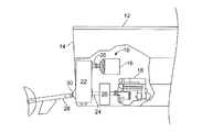
次に図面、特に図1を参照すると、単一の動力出力部30を有する好ましい実施形態のハイブリッド動力デバイス10を含み、トランサム14を有する船舶12の後方部分の切欠側面図が示されている。
Referring now to the drawings, and in particular to FIG. 1, a cutaway side view of a rear portion of a
ハイブリッド動力デバイス10は、2つの原動機、すなわち、電気モータ16ならびにディーゼルまたはガソリン動力エンジンとすることができる内燃機関18とを利用する。伝動装置20は、原動機18の後ろまたはその下流で原動機18に動作可能に接続される。伝動装置20は、好ましくは、ツインディスク,インク.(本社所在地:ウィスコンシン州ラシーンから入手可能なMGXシリーズ伝動装置(QuickShift(登録商標)伝動装置)またはMGシリーズ伝動装置であり、1つの好ましい実施形態では、二速伝動装置である。
The
原動機内燃機関18および伝動装置20は、たとえば、伝動出力シャフト24を経由して、ギヤボックス22に接続されている。さらに、原動機電気モータ16が、たとえば、伝動出力シャフト26を経由して、ギヤボックス22に接続されている。動力伝達デバイス、たとえば、ギヤボックス22は、原動機16、18から送達された動力を1つまたは複数の動力成分に変換する。この例示的な実施形態では、ドライブアセンブリ28について、動力出力シャフト30を介した単一の動力成分が存在する。水中型ドライブ、ウォータジェットなどを含む他のドライブも企図され、それらが十分に本発明の範囲に含まれることに留意すると、ドライブアセンブリ28は、好ましくは、船舶用サーフェスドライブ、たとえば、ツインディスク,インク.から入手可能なARNESON(登録商標)サーフェスドライブである。
The prime mover
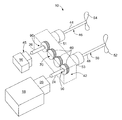
次に図2を参照すると、2つの動力出力部44、48を有する本発明のハイブリッド動力デバイス40の別の実施形態を含み、トランサム14を有する船舶12の後方部分の切欠頂面図が示されている。
Referring now to FIG. 2, there is shown a cutaway top view of the rear portion of a
ハイブリッド動力デバイス40は、2つの原動機、すなわち、電気モータ16と、ディーゼル、タービンまたはガソリン動力エンジンとすることができる内燃機関18とを利用する。伝動装置20は、原動機18の後ろまたはその下流で原動機18に動作可能に接続される。伝動装置20は、好ましくは、ツインディスク,インク.(本社所在地:ウィスコンシン州ラシーンから入手可能なMGXシリーズ伝動装置(QuickShift(登録商標)伝動装置)またはMGシリーズ伝動装置であり、1つの好ましい実施形態では、二速伝動装置である。
The
原動機内燃機関18は、出力部25を経由して伝動装置20に接続され、伝動装置20は、たとえば、伝動出力シャフト24を経由して、動力分割ギヤボックス42に接続される。さらに、原動機電気モータ16は、たとえば、出力シャフト26を経由して、動力分割ギヤボックス42に接続される。動力分割ギヤボックス42は、原動機16、18のいずれかまたは両方から送達された動力を、ドライブアセンブリ46のための動力出力シャフト44とドライブアセンブリ50のための動力出力シャフト48とを介した2つの出力動力成分に変換する。水中型ドライブ、ウォータジェットなどを含む他のドライブも企図され、それらが十分に本発明の範囲に含まれることに留意すると、ドライブアセンブリ46、50は、好ましくは、船舶用サーフェスドライブ、たとえば、ツインディスク,インク.から入手可能なARNESON(登録商標)サーフェスドライブである。
The prime mover
次に図2および図3を参照すると、動力分割ギヤボックス42を備えるハイブリッド動力デバイス40は、原動機16、18から動力を入力し、動力(またはその成分)を分割してそれをドライブアセンブリ46、50の対に分配する一方で、船舶12とドライブアセンブリ46、50との間にインターフェースを提供する。これに関して、ハイブリッド動力デバイス40により、原動機16、18の対を備える船舶12は、反対方向に回転するプロペラ52、54の対を利用することを可能にする(図3)。
Referring now to FIGS. 2 and 3, a
さらに図2および図3を参照すると、1つの実施形態では、原動機16は、250馬力の電気モータとすることができ、原動機18は、実質的に同じ馬力をもつディーゼル内燃機関とすることができ、動力伝達デバイス42は、高いRPMをもつ内燃機関に適応するように他の比、たとえば、2対1が企図されるが、参照により本明細書に明確に組み込まれる2009年6月4日付けで出願された米国特許出願第12/478,329号に開示されたもののような1対1比動力分割ギヤボックスとすることができる。電気モータ16は、たとえば、2対1比または3対1比によって、(図3に示すように)その出力シャフト26のRPMを低減するためのそれ自体のギヤボックス45を有してもよく、あるいは、電気モータ16は、(図2に示すように)ギヤボックス42に直接的に接続してもよい。同様に、内燃機関18は、それ自体のギヤボックス20を有することができる。
Still referring to FIGS. 2 and 3, in one embodiment,
原動機16、18のいずれかまたは両方をアクティブ化して、対応する出力部26、24とすることができる。原動機16、18のいずれかをアクティブ化した場合、船舶の速度は、たとえば、36ノットとなり得る。原動機16、18の両方をアクティブ化した場合、船舶の速度は、たとえば、50ノットとなり得る。両方の原動機をアクティブ化した場合、電気モータ16は、内燃機関18に対するブースタとして動作することができ、その場合、内燃機関ギヤボックス20は、電気モータに対して内燃機関のRPMをより高くするために、たとえば、ある速度における最大出力が1500RPMである2速ギヤボックスとすることができる。また、原動機16、18の両方をアクティブ化した場合、ハイブリッド動力デバイスは、両方の原動機が、動力伝達ギヤボックス42への動力入力に対して実質的に均等に寄与するように、あるいは、制御システムが、以下で説明するようにギヤボックス42への動力入力を(図1の実施形態では動力伝達デバイス22への動力入力についても同様に)均等化することができるように設計することができる。
Either or both of the
図3をより詳細に参照すると、原動機16、18のいずれかは、クラッチと、たとえば、ドライブ46、50にトルクをそれぞれ伝達するためのクラッチ51、53と動力伝達経路を機械的に係合することによって、ドライブ46、50にその動力を伝達することができる。代替的には、1つまたは複数のクラッチが、原動機16、18からギヤボックス42またはギヤボックス10への動力の伝達を制御することができる(図示せず)。さらに、各原動機16、18は、動力源、すなわち、電気モータ16のためのバッテリーパックおよび内燃機関18のための燃料タンク(図示せず)を有する。
Referring to FIG. 3 in more detail, either
次に図3Aを参照すると、制御システム15は、出力速度、出力パワー、出力負荷などのような様々な電気モータ16および内燃機関18の信号を監視することによって、ハイブリッド動力デバイス10のフレキシブルコントロールを行うことができる。所望の結果、たとえば、原動機16と原動機18との間の実質的に均等な動力分配、最適な動力、速度および/または燃焼効率を達成するために、電気モータ16および内燃機関18を、独立してまたは組み合わせて制御することができる。制御システム15は、制御インターフェースデバイスECU(engine control unit:エンジン制御ユニット)29、31を用いて原動機16、18を監視する、および/または制御することができる。制御信号およびステータス信号は、ハーネス27として示されるワイヤード接続を介して(代替的には、図示されていないワイヤレス接続を介して)、主制御ユニット23によって送受信することができる。また、制御システム15は、制御およびステータスをユーザに提供するユーザインターフェース33を有することができ、ユーザインターフェース33は、別個でも、あるいは、主制御ユニット23と一体化してもよい。
Referring now to FIG. 3A, the
図3Aを続けて参照すると、制御システム15は、接続解除デバイス19、21をそれぞれ使用して所望の結果を最適化するために、原動機16、18のいずれかのオンザフライの係合または係合解除を管理することができる。原動機16、18のいずれかまたは両方は、様々な手段によって、ギヤボックス42から物理的に接続解除可能とすることができる。たとえば、接続解除デバイスのいずれかまたは両方は、クラッチとすることができる。また、1つの原動機のみを使用する際の抗力を低減するために、シャフト26、24への動力接続の制御が望ましいことがあり、かかる制御は、いずれかの原動機のオンザフライ接続/接続解除をシームレスに管理するための制御システムの能力を補助することができる。これにより、原動機が故障した場合の非常用「リンプホーム」モードが可能になり得る。また、制御システム15は、たとえば、速度または効率を最適化する、選択された状況で手動制御を可能にするなど、他の所望の結果を達成するために、接続解除デバイス19、21を管理することができる。
With continued reference to FIG. 3A, the
制御システム15は、バスを用いて直接的または間接的に様々なセンサを監視することが可能なマイクロプロセッサベースのECUで構成することができ、次いで、たとえば、関連付けられたハーネス27を介して、所望の応答を達成するために両方の原動機ECU29、31と通信し、接続解除デバイスを制御する。センサは、所望の結果を達成するためのデータを取得するために必要とされるような、速度、温度、圧力などを含むことができる。
The
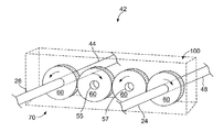
次に図2〜図4を参照すると、動力分割ギヤボックス42は、ギヤトレイン70、または動力分割ギヤボックス42の他の様々な構成要素を少なくとも部分的に収容している。ギヤボックスハウジング100は機械的に取り付けることができ、ドライブアセンブリ46、50とトランサム14との間のインターフェース構造を提供することができる。これは、トランサム14にギヤボックスハウジング100を取り付けることができ、ギヤボックスハウジング100にファイナルドライブアセンブリ46、50を取り付けることができるからである。ギヤボックスハウジング100は、ファイナルドライブアセンブリ46、50をトランサム14に接続するので、ファイナルドライブアセンブリ46、50を通じてトランサム14に送達された推進力ならびに動力分割ギヤボックス42およびドライブアセンブリ46、50の重量の印加も分散させる。
2 to 4, the power
次に、図4だけでなく図2および図3も参照すると、ギヤトレイン70は、入力部24、26を通じて受け取った動力を機械的に分割して、出力部44、48を通じて送達し、それにより、ドライブアセンブリ46、50を駆動することができる。ギヤトレイン70は、互いに噛合し、したがって、同時に回転する複数のギヤ60を含む。ギヤ60は、好ましくは、螺旋状に切られた歯を有しており、かつ、ギヤトレイン70のギヤ60は1つおきに同じ方向に回転し、直接隣接するギヤ60は反対方向に回転するように互いに径方向に並べられている。隣接する径方向に係合しているギヤ同士は反対方向に回転するので、直観的に、2つの中間のギヤ(または2の倍数個の複数のギヤ)によって互いに離間したギヤ60同士は反対方向に回転する。それに応じて、ギヤトレイン70は、ギヤトレイン70中のギヤ60のいずれか1つに動力を入力することができ、そして、2つの中間のギヤ60(または2の倍数個の複数のギヤ)によって互いに離間したギヤ60を通じて動力を送達することによって、出力部44、48を反対方向の回転させることができる。したがって、代替的には、反対方向に回転する出力部をギヤ55、57の中心に接続することができるが、これは好ましくはない。
Next, referring not only to FIG. 4 but also to FIGS. 2 and 3, the
入力部24、26および出力部44、48は、ギヤ60とば別の個別の異なる構成要素である必要はなく、むしろ、個々のギヤ60と一体化することができることが企図される。たとえば、入力部24は、出力シャフト44のスプライン様の端部を受けるギヤ60のうちの1つのスプライン様の内周面とすることができる。同様に、出力部44、48は、ドライブアセンブリ46、50に接続された出力シャフト44、48のスプライン様の端部を受容し駆動するギヤ60のうちの1つのスプライン様の内周面とすることができる。
It is contemplated that the
次に図5だけでなく図1も参照すると、ギヤトレイン70は、入力部24、26を通じて受け取った動力を機械的に伝達して、出力部30を通じて送達し、それにより、ドライブアセンブリ28を駆動することができる。ギヤトレイン70は、互いに噛合し、したがって同時に回転する複数のギヤ60を含む。ギヤ60は、好ましくは、螺旋状に切られた歯を有しており、かつ、ギヤトレイン70のギヤ60は1つおきに同じ方向に回転し、直接隣接するギヤ60は反対方向に回転するように互いに径方向に並べられている。図5には入力部が最も外側のギヤに接続された状態が示されているが、ギヤトレイン70は、ギヤトレイン70中のギヤ60のうちいずれか1つに動力を入力することができる。同様に、ギヤトレイン70は、中央のギヤ60から、図示された出力シャフト30または他のギヤのいずれかに出力部を送達することができる。
Referring now to FIG. 1 as well as FIG. 5, the
入力部24、26および出力部30は、ギヤ60とは別の個別の異なる構成要素である必要はなく、むしろ、個々のギヤ60と一体化することができることが企図される。たとえば、入力部24は、入力シャフト24のスプライン様の端部を受けるギヤ60のうちの1つのスプライン様の内周面とすることができる。同様に、出力部30は、ドライブアセンブリ28に接続された出力シャフト30のスプライン様の端部を受容し駆動するギヤ60のうちの1つのスプライン様の内周面とすることができる。
It is contemplated that the
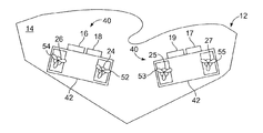
次に図6を参照すると、各々が動力分割ギヤボックス42を有するハイブリッド動力デバイス40の対を使用することによって、原動機16、18および17、19の2つの対を有する船舶12は、反対方向に回転するプロペラ52、54および53、55の2つの対を利用することができ、それにより、船舶12には、トランサム14の右舷側および左舷側の各々に反対方向に回転するプロペラを含む合計で4つのプロペラが組み込まれている。
Referring now to FIG. 6, by using a pair of
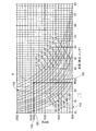
次に図7および図8、さらに図3を参照して、最適に効率的なプロパルサージオメトリにおける対応を示す、2つの速度のデュアルおよびシングル原動機係合を立証する例について説明する。図7を詳細に参照すると、約250HPの単一の原動機16または18が係合され、原動機の出力部が実質的に1500RPMで回転するように構成された実施形態では、効率が最適なプロペラ径は、図7を利用して、1)縦軸上の1500RPM点112および対応する1500RPM水平線114を特定し、2)馬力(HP)曲線と1500RPM水平線114との交差をロケーティングするかまたは近似し、3)横軸118上の対応する交差からインチ単位でプロペラ径を読み取るようにして判断することができる。たとえば、250HPの所与の原動機の場合、対応するHP曲線はなく、したがって、250HPよりも大きい最も近接した曲線と、250HPよりも小さい最も近接した曲線とをロケーティングする。したがって、図7を使用すると、200HP曲線120および300HP曲線122をロケーティングする。1500RPM水平線114との交差点、すなわち、点Aおよび点Bを通る曲線120および122を辿る。250HPはほぼ中間点なので、点Aと点Bとの間の線を二等分し、その点から垂直線124を引き、点Cで横軸118をと交差させる。最後に、横軸の点Cから、最適なプロペラ径(この場合では、約23.75インチ)を読み取る。したがって、1500RPMで作動する任意の250HP原動機は、プロペラの直径が約24インチである場合に、回転速度が最適となる。
Referring now to FIGS. 7 and 8, and further to FIG. 3, an example demonstrating dual speed dual and single prime mover engagement, showing the correspondence in optimally efficient propulser geometry, will be described. Referring to FIG. 7 in detail, in an embodiment where a single
次に図8をより詳細に参照すると、プロペラ径および馬力を仮定して、船舶の速度を判断することを実行することができる。たとえば、24インチ径のプロペラの場合、1)対応する24インチ曲線132を選択し、2)横軸上で1500RPMをロケーティングし、3)24インチ曲線132の交差(点Fとして示される)を通して垂直線136を引き、4)交差Fから縦軸まで水平線148を引いてノットを示し、5)、対応する船の速度を30ノットと読み取る。
Referring now to FIG. 8 in more detail, it can be performed assuming the propeller diameter and horsepower to determine the speed of the vessel. For example, for a 24 inch diameter propeller, 1) select the corresponding 24
同様に、係合した両方の原動機16、18を用いて船舶を作動させたとき、動力は、実質的に500HPに達する。再び図7を参照すると、プロパルサーのブレードは、その直径を示す垂直線124を有する。500HP曲線と直径124とは、点Cで交差する。点Cから縦軸に垂直線を引くと、約24インチのプロパルサーのブレード径は、約500HPで、1900RPMをもたらすことになることが分かる。速度を計算するために図8を再び参照すると、1900RPMを横軸上にロケーティングし、24インチ曲線との交差まで垂直線を引く。交差から縦軸まで水平線を引き、速度を約38ノットと判断することによって、速度を判断する。ブレード径が24インチであるプロパルサーは、それぞれ約30ノットおよび約38ノットの速度(1500RPMおよび1900RPMに対応する)での250馬力および500馬力で動作する場合に最も効率的である。
Similarly, when the ship is operated with both engaged
再び図3を参照すると、両方の原動機16、18が実質的に均等に寄与する別の実施形態にでは、内燃機関18および電気モータ16は、たとえば、1500RPMで回転するように、ギヤボックス42に噛み合うことができる。10トンの船舶の場合、50ノットを達成する推進効率は、プロペラ52、54を駆動したときには実質的に0.69であり、それには、プロペラが約23.5インチ×42インチでサイズ決定されることが必要である。重要なことに、プロペラを同じようにサイズ決定することは、たとえば、いずれかの原動機が36ノットのフルスピードで係合されている場合に最も効率的である。さらに重要なことに、原動機16、18から実質的に均等な動力を提供することによって、(プロペラまたはウォータジェットのいずれかについての)プロパルサーの出力部の最適なサイズ決定は、原動機の最高速度およびデュアル原動機の最高速度について同じになる。
Referring again to FIG. 3, in another embodiment in which both
さらに図3を参照すると、内燃機関原動機18は、低高ギヤを有するギヤボックス20を有することができるが、電気原動機16は、その実質的にフラットな動力曲線に起因して、ギヤボックスを有しないことがある。1つの実施形態では、内燃機関18は、ギヤボックスへの出力部24のRPMを約1500RPMまで高める1:1.25のギヤ比を有するギヤボックス20に約1500RPMの出力を提供していることがある。これは、2つの原動機16、18のうちのいずれかまたは1つのみが係合している場合に、36ノットの速度をもたらすことができる。23.524×42インチのプロペラサイズ(すなわち、42インチピッチの23.524インチ径のブレード)は、0.69効率で最適のままである。
Still referring to FIG. 3, the internal combustion engine
23.5×42のサイズは、50ノットで4%スリップになり、36ノットで16%スリップになる。この12%のスリップ差は、サーフェスプロペラおよび水中プロペラの両方、より低い速度、ならびにより高いスリップについての推進ノルムと一致している。どちらの場合もプロペラ効率が0.69であるという事実は、サーフェスプロペラのプロプライエタリなトンネルテストデータから来る。 The 23.5 × 42 size is 4% slip at 50 knots and 16% slip at 36 knots. This 12% slip difference is consistent with the propulsion norm for both surface and underwater propellers, lower speeds, and higher slips. The fact that in both cases the propeller efficiency is 0.69 comes from the proprietary tunnel test data of the surface propeller.
動力デバイス10は、必ずしも上述した実施形態に限定されるものではなく、他の実施形態を含み得る。これらの変更の範囲については、上記で論じている。その他の範囲は、添付の特許請求の範囲から明らかになるであろう。
The
とにかく、本発明の趣旨から逸脱することなく、本発明に対して多くの変更および修正を行い得ることを留意されたい。これらの変更の範囲については、上記で論じている。その他の範囲については、添付された発明の陳述から明らかになるであろう。 In any event, it should be noted that many changes and modifications may be made to the present invention without departing from the spirit of the invention. The scope of these changes is discussed above. Other areas will become apparent from the appended description of the invention.
Claims (20)
前記動力伝達デバイスと連通する第2の動力伝達エレメントを有し、それにより、第2のトルクを前記動力伝達デバイスの第2の入力部に伝達する、内燃機関と、
動力入力エレメントを有し、前記動力入力エレメントに印加されたトルクが、船舶を動かすための推進力を発生させる、少なくとも1つのプロパルサーと、
を備え、
前記動力伝達デバイスが、前記少なくとも1つのプロパルサーの前記動力入力エレメントと連通する少なくとも1つの出力部と、動力伝達アセンブリとをさらに備え、
前記動力伝達アセンブリが、
1)前記第1のトルクまたは前記第2のトルクが所与の時間に印加されたとき、前記少なくとも1つのプロパルサーの前記動力入力エレメントと連通する前記出力部の実質的に対応するトルクが存在するように構成され、かつ、
2)前記第1の入力部に印加された前記第1のトルクと前記第2の入力部に印加された前記第2のトルクとが実質的に同じ毎分回転数であるとき、前記少なくとも1つのプロパルサーの前記動力入力エレメントと連通する前記出力部の実質的に対応する毎分回転数が生じるように構成される、
船舶のための推進システム。 An electric motor having a first power transmission element in communication with the power transmission device, thereby transmitting a first torque to a first input of the power transmission device;
An internal combustion engine having a second power transmission element in communication with the power transmission device, thereby transmitting a second torque to a second input of the power transmission device;
At least one propulsor having a power input element, wherein the torque applied to the power input element generates a propulsive force to move the ship;
With
The power transmission device further comprises at least one output in communication with the power input element of the at least one propulsor; and a power transmission assembly;
The power transmission assembly comprises:
1) When the first torque or the second torque is applied at a given time, there is a substantially corresponding torque of the output that communicates with the power input element of the at least one propulsor And configured to
2) When the first torque applied to the first input unit and the second torque applied to the second input unit have substantially the same number of revolutions per minute, the at least 1 Configured to produce substantially corresponding revolutions per minute of the output of the propulsor in communication with the power input element;
Propulsion system for ships.
請求項1に記載の推進システム。 The at least one propulsor is a single propulsor and the at least one power transmission device has a single output;
The propulsion system according to claim 1.
請求項1の推進システム。 The at least one propulsor includes two propulsers, and the at least one power transmission device has two outputs;
The propulsion system of claim 1.
請求項1の推進システム。 Full power using both the first torque applied to the first input section and the second torque applied to the second input section at substantially the same number of revolutions per minute. Further comprising a propulsion thruster configured for optimum efficiency when activated;
The propulsion system of claim 1.
請求項4に記載の推進システム。 A propulsor thruster is further provided, wherein the thruster is configured for optimum efficiency when operated at half power using an independent torque applied to the first input portion or the second input portion. The
The propulsion system according to claim 4.
請求項1に記載の推進システム。 The first power transmission element of the electric motor and the second power transmission of the internal combustion engine so that the first input section and the second input section rotate at substantially the same number of revolutions per minute. An RPM equalization device configured to control power transmission from the element;
The propulsion system according to claim 1.
請求項1に記載の推進システム。 Further comprising a user controlled speed adjustment element configured to control the speed of the vessel;
The propulsion system according to claim 1.
請求項1に記載の推進システム。 Further comprising an automatic mode selection element configured to control application of power from the electric motor and the internal combustion engine so that any power source can be used independently or in combination.
The propulsion system according to claim 1.
請求項1に記載の推進システム。 The internal combustion engine is configured to operate over a range of power output including a power output that causes the second input unit to rotate at a higher speed per minute than the electric motor. Become,
The propulsion system according to claim 1.
請求項1に記載の推進システム。 The electric motor is configured to operate over a range of power outputs including a power output that causes the first input section to rotate at a higher speed per minute than the second input section; The electric motor becomes a booster,
The propulsion system according to claim 1.
請求項1に記載の推進システム。 The second power transmission element of the internal combustion engine includes a rotatable shaft and a two-speed gearbox that reduces the rotational speed of the second input unit.
The propulsion system according to claim 1.
請求項1に記載の推進システム。 The power transmission element driven by the internal combustion engine communicates with a generator that provides power to the ship or charges a stored power source;
The propulsion system according to claim 1.
請求項12に記載の推進システム。 The generator is the electric motor or a dedicated generator;
The propulsion system according to claim 12.
請求項1に記載の推進システム。 The one or more propulsers are selected from the group consisting of surface propeller drives, conventional propeller equipment, water jets, outboard drives, and pod drives;
The propulsion system according to claim 1.
請求項1に記載の推進システム。 The power transmission device is a gear box and the power transmission assembly comprises a gear;
The propulsion system according to claim 1.
前記船舶のトランサムに対して固定されたギヤボックスハウジングと、
前記ギヤボックスハウジング内に装着されたギヤトレインを備え、前記ギヤトレインが、前記第1の入力部および前記第2の入力部から動力を受容し、前記2つの動力伝達デバイスへの前記動力を実質的に2等分する、動力伝達アセンブリと、
をさらに備えるギヤボックスである、
請求項3に記載の推進システム。 The power transmission device is
A gear box housing fixed to the transom of the ship;
A gear train mounted in the gear box housing, wherein the gear train receives power from the first input portion and the second input portion, and substantially transmits the power to the two power transmission devices. A power transmission assembly that bisects
A gear box further comprising:
The propulsion system according to claim 3.
請求項16に記載の推進システム。 The gear train includes at least four gears that are substantially radially aligned with each other and meshing with their respective outer peripheral surfaces, whereby at least a first pair of the at least four gears is a first Rotating in a direction, at least a second pair of the at least four gears rotating in a second opposing direction
The propulsion system according to claim 16.
請求項17に記載の推進システム。 The at least one propulsor includes a first propulsor and a second propulsor, and the first propulsor is driven by one gear of the first pair of the at least four gears. The second propulsor is driven by one gear of a second pair of the at least four gears, whereby the outputs of the two power transmission devices rotate in opposite directions;
The propulsion system according to claim 17.
請求項1に記載の推進システム。 Further comprising at least one clutch, application of torque of the electric motor is controlled by the clutch, and application of torque of the internal combustion engine is controlled by the clutch;
The propulsion system according to claim 1.
いずれかのまたは両方の原動機によって生成された動力を、ギヤボックスに収容されたギヤトレインの中に受容することと、
前記動力を、1つまたは2つの動力成分のいずれかとして出力することと、
前記1つまたは2つの動力成分を、対応する1つまたは2つのクラッチアセンブリの中に受容することと、
前記1つまたは2つの動力成分を、前記クラッチアセンブリを通して、それに動作可能に接続された対応する1つまたは2つのプロパルサーに選択的に伝達し、それにより、船舶を推進することと、
を含む、
船舶を推進する方法。 Operating a plurality of prime movers, wherein one prime mover is an electric motor and one prime mover is an internal combustion engine;
Receiving power generated by one or both prime movers in a gear train housed in a gear box;
Outputting the power as either one or two power components;
Receiving said one or two power components in corresponding one or two clutch assemblies;
Selectively transmitting the one or two power components through the clutch assembly to corresponding one or two propulsers operatively connected thereto, thereby propelling the ship;
including,
How to propel a ship.
Applications Claiming Priority (3)
| Application Number | Priority Date | Filing Date | Title |
|---|---|---|---|
| US13/081,282 | 2011-04-06 | ||
| US13/081,282 US8795008B2 (en) | 2011-04-06 | 2011-04-06 | Two-into-two or one hybrid power device for a marine vehicle |
| PCT/US2012/032384 WO2013106022A2 (en) | 2011-04-06 | 2012-04-05 | Two-into-two or one hybrid power device for a marine vehicle |
Publications (2)
| Publication Number | Publication Date |
|---|---|
| JP2014512302A true JP2014512302A (en) | 2014-05-22 |
| JP2014512302A5 JP2014512302A5 (en) | 2015-05-21 |
Family
ID=46966455
Family Applications (1)
| Application Number | Title | Priority Date | Filing Date |
|---|---|---|---|
| JP2014503999A Pending JP2014512302A (en) | 2011-04-06 | 2012-04-05 | 2-2 or 2-1 hybrid power device for ships |
Country Status (6)
| Country | Link |
|---|---|
| US (1) | US8795008B2 (en) |
| EP (1) | EP2694363A4 (en) |
| JP (1) | JP2014512302A (en) |
| CN (1) | CN103582594A (en) |
| BR (1) | BR112013025801A2 (en) |
| WO (1) | WO2013106022A2 (en) |
Cited By (3)
| Publication number | Priority date | Publication date | Assignee | Title |
|---|---|---|---|---|
| KR101731364B1 (en) * | 2014-07-14 | 2017-04-28 | 조수동 | Screw of ship |
| US10507897B2 (en) | 2016-06-07 | 2019-12-17 | Yamaha Hatsudoki Kabushiki Kaisha | Vessel propulsion apparatus |
| WO2020054217A1 (en) * | 2018-09-13 | 2020-03-19 | ヤンマー株式会社 | Ship propulsion hybrid system |
Families Citing this family (19)
| Publication number | Priority date | Publication date | Assignee | Title |
|---|---|---|---|---|
| US9321516B1 (en) | 2013-01-31 | 2016-04-26 | Consortium de Recherche BRP—Universite de Sherbrooke S.E.N.C. | Hybrid propulsion system for a watercraft |
| CN103803048B (en) * | 2014-02-17 | 2016-04-20 | 陈卫文 | Cross-type two-stroke diesel low speed diesel engine deceleration propelling unit |
| NL2012904B1 (en) * | 2014-05-28 | 2016-06-08 | Ihc Holland Ie Bv | Gearbox for a dredging vessel. |
| CN105564623B (en) * | 2016-01-21 | 2017-11-07 | 北京工业大学 | Naval vessel bidirectional clutch axis system |
| CN105691578B (en) * | 2016-03-04 | 2018-04-03 | 北京工业大学 | The parallel double rolling key clutch axis system in naval vessel |
| CN105818953A (en) * | 2016-03-17 | 2016-08-03 | 哈尔滨博展科技有限公司 | Power system for double-fuel ship |
| JP6695216B2 (en) * | 2016-06-07 | 2020-05-20 | ヤマハ発動機株式会社 | Ship propulsion |
| IT201600072139A1 (en) * | 2016-07-11 | 2018-01-11 | Fpt Ind Spa | BOAT WITH HYBRID PROPULSION |
| CN108482622B (en) * | 2018-04-11 | 2019-08-30 | 钦州学院 | Autonomous underwater vehicle and its six propellers simultaneously advance mechanism |
| WO2020108749A1 (en) | 2018-11-28 | 2020-06-04 | Volvo Penta Corporation | Mounting arrangement for a propulsion unit |
| WO2020144759A1 (en) * | 2019-01-09 | 2020-07-16 | 株式会社Ihi原動機 | Hybrid propulsion ship operation method and hybrid propulsion ship |
| JP7293035B2 (en) * | 2019-08-09 | 2023-06-19 | 川崎重工業株式会社 | vessel |
| CN111994245A (en) * | 2020-09-01 | 2020-11-27 | 王晓明 | Sea surface low-resistance high-speed running system |
| JP7441776B2 (en) | 2020-11-18 | 2024-03-01 | 三菱造船株式会社 | Ships and how to navigate them |
| US20220326704A1 (en) * | 2021-03-31 | 2022-10-13 | Beta Air, Llc | Methods and systems for flight control configured for use in an electric aircraft |
| US11524767B2 (en) * | 2021-03-31 | 2022-12-13 | Beta Air, Llc | Methods and systems for flight control configured for use in an electric aircraft |
| FR3129363A1 (en) * | 2021-11-22 | 2023-05-26 | Bluenav | Motorization control system of a boat with hybrid motorization |
| CN114435569A (en) * | 2022-02-17 | 2022-05-06 | 武汉劳雷绿湾船舶科技有限公司 | Half-submerged oar advancing device of adjustable pitch |
| CN116353804A (en) * | 2023-04-28 | 2023-06-30 | 中国船舶科学研究中心 | Electric semi-submerged propeller propelling device and driving method thereof |
Citations (2)
| Publication number | Priority date | Publication date | Assignee | Title |
|---|---|---|---|---|
| JP2004345628A (en) * | 2004-03-26 | 2004-12-09 | Niigata Power Systems Co Ltd | Driving control method for vessel |
| WO2010141873A2 (en) * | 2009-06-04 | 2010-12-09 | Twin Disc, Inc. | Marine power splitting gearbox |
Family Cites Families (37)
| Publication number | Priority date | Publication date | Assignee | Title |
|---|---|---|---|---|
| US3225732A (en) | 1962-05-11 | 1965-12-28 | Carlsen Kurt | Reversible marine propulsion system |
| JPS4927832B1 (en) * | 1966-08-11 | 1974-07-20 | ||
| NO800935L (en) * | 1980-03-31 | 1981-10-01 | Moss Rosenberg Verft As | LNG SHIP PROGRAMMING MACHINE. |
| JPS6018495A (en) * | 1983-07-12 | 1985-01-30 | Mitsubishi Heavy Ind Ltd | Electrical propelling apparatus for emergency |
| US4790782A (en) * | 1988-02-26 | 1988-12-13 | Brunswick Corporation | Balanced marine surfacing drive |
| US4846741A (en) * | 1988-08-10 | 1989-07-11 | Betsinger Thomas R | Heel compensating steering arrangement for high speed boats |
| JP3253995B2 (en) * | 1991-11-19 | 2002-02-04 | 三菱重工業株式会社 | Marine propulsion device |
| US5327987A (en) | 1992-04-02 | 1994-07-12 | Abdelmalek Fawzy T | High efficiency hybrid car with gasoline engine, and electric battery powered motor |
| GB2275309B (en) | 1993-02-22 | 1997-10-29 | Yang Tai Her | Differential coupling and compounding system |
| NZ500627A (en) | 1997-04-18 | 2001-01-26 | Transp Energy Systems Pty Ltd | Hybrid propulsion system for road vehicles with three drive units coupled to power-splitting transmission |
| FR2789048B1 (en) * | 1999-02-01 | 2001-08-10 | Robert Edmond Lipp | CYCLOID PROPELLER WHOSE SHAPE AND ORIENTATION OF POLES ARE ELASTICALLY MODIFIED BY HYDRAULIC PUSH |
| CN1250733A (en) * | 1999-09-30 | 2000-04-19 | 交通部上海船舶运输科学研究所 | Method for controlling joint operating of diesel engine with single speed controller |
| CN2417124Y (en) * | 1999-12-30 | 2001-01-31 | 饶坚 | Controllable means for propulsion of ship with single engine and double paddle |
| JP4445089B2 (en) * | 2000-03-28 | 2010-04-07 | ヤンマー株式会社 | Ship propulsion device |
| CA2309759A1 (en) | 2000-05-26 | 2001-11-26 | Cke Technologies Inc. | Use of a continuously variable power split transmission in a hybrid vehicle |
| DE10061578A1 (en) | 2000-12-11 | 2002-06-27 | Siemens Ag | Hybrid propulsion for ships |
| DE10063338B4 (en) | 2000-12-19 | 2007-03-01 | Blohm + Voss Gmbh | Device for propelling a ship |
| US6361387B1 (en) * | 2001-01-19 | 2002-03-26 | Brunswick Corporation | Marine propulsion apparatus with dual driveshafts extending from a forward end of an engine |
| US6464608B2 (en) | 2001-02-08 | 2002-10-15 | New Venture Gear Inc. | Transfer case for hybrid vehicle |
| DE10111910A1 (en) | 2001-03-13 | 2002-09-19 | Man B&W Diesel A/S, Copenhagen Sv | Hybrid diesel mechanical and electrical drive system for safe and adaptable ship operation |
| JP4445167B2 (en) * | 2001-09-11 | 2010-04-07 | ヤンマー株式会社 | Ship power generation and propulsion equipment |
| US7520354B2 (en) | 2002-05-02 | 2009-04-21 | Oshkosh Truck Corporation | Hybrid vehicle with combustion engine/electric motor drive |
| US20050107198A1 (en) | 2003-11-19 | 2005-05-19 | Henryk Sowul | Hybrid powertrain |
| US7140461B2 (en) | 2003-11-26 | 2006-11-28 | Oshkosh Truck Corporation | Power splitting vehicle drive system |
| US7070469B2 (en) | 2004-09-15 | 2006-07-04 | James Stallings | Dual propeller surface drive propulsion system for boats |
| DE102004050757A1 (en) | 2004-10-16 | 2006-04-27 | Daimlerchrysler Ag | Set of gears and hybrid dual-clutch transmission |
| US7517264B2 (en) | 2004-10-27 | 2009-04-14 | Geared Up Systems, Inc. | Power boat drive system with multiple gearboxes |
| TWI330218B (en) | 2004-10-29 | 2010-09-11 | Tai Her Yang | Split serial-parallel hybrid dual-power drive system |
| US7424924B2 (en) | 2005-08-15 | 2008-09-16 | Ford Global Technologies, Llc | Hybrid electric vehicle powertrain with torque transfer case |
| DE102005057607B3 (en) | 2005-12-02 | 2007-04-05 | Hytrac Gmbh | Hybrid drive for vehicle e.g. passenger car, has planetary wheels with planetary gear having output shaft, and brake that is released in lateral course of switching process of coupling for generation of one of drive areas |
| JP2008062905A (en) | 2006-09-11 | 2008-03-21 | Yamaha Marine Co Ltd | Ship propeller and method of operating the same |
| DE102006045502A1 (en) | 2006-09-27 | 2008-04-03 | Jungheinrich Ag | Device for controlling a hybrid drive system for a motor vehicle, in particular an industrial truck |
| DE102006058947A1 (en) | 2006-12-14 | 2008-06-19 | Dr.Ing.H.C. F. Porsche Ag | Double clutch for a hybrid drive |
| AU2008257541C1 (en) | 2007-06-01 | 2014-08-28 | Siemens Aktiengesellschaft | Method and apparatus for operation of a marine vessel hybrid propulsion system |
| KR100969085B1 (en) | 2007-09-05 | 2010-07-09 | 현대자동차주식회사 | Power transmission device for hev |
| US9028285B2 (en) | 2008-08-29 | 2015-05-12 | Nt Consulting International Pty Limited | Hybrid marine drivetrain |
| FR2949750B1 (en) * | 2009-09-04 | 2011-10-07 | Converteam Technology Ltd | PROPULSION CHAIN |
-
2011
- 2011-04-06 US US13/081,282 patent/US8795008B2/en not_active Expired - Fee Related
-
2012
- 2012-04-05 BR BR112013025801A patent/BR112013025801A2/en not_active Application Discontinuation
- 2012-04-05 JP JP2014503999A patent/JP2014512302A/en active Pending
- 2012-04-05 CN CN201280026432.9A patent/CN103582594A/en active Pending
- 2012-04-05 WO PCT/US2012/032384 patent/WO2013106022A2/en active Application Filing
- 2012-04-05 EP EP12865026.4A patent/EP2694363A4/en not_active Withdrawn
Patent Citations (2)
| Publication number | Priority date | Publication date | Assignee | Title |
|---|---|---|---|---|
| JP2004345628A (en) * | 2004-03-26 | 2004-12-09 | Niigata Power Systems Co Ltd | Driving control method for vessel |
| WO2010141873A2 (en) * | 2009-06-04 | 2010-12-09 | Twin Disc, Inc. | Marine power splitting gearbox |
Cited By (3)
| Publication number | Priority date | Publication date | Assignee | Title |
|---|---|---|---|---|
| KR101731364B1 (en) * | 2014-07-14 | 2017-04-28 | 조수동 | Screw of ship |
| US10507897B2 (en) | 2016-06-07 | 2019-12-17 | Yamaha Hatsudoki Kabushiki Kaisha | Vessel propulsion apparatus |
| WO2020054217A1 (en) * | 2018-09-13 | 2020-03-19 | ヤンマー株式会社 | Ship propulsion hybrid system |
Also Published As
| Publication number | Publication date |
|---|---|
| WO2013106022A2 (en) | 2013-07-18 |
| WO2013106022A3 (en) | 2013-10-03 |
| CN103582594A (en) | 2014-02-12 |
| BR112013025801A2 (en) | 2016-12-20 |
| US20120258639A1 (en) | 2012-10-11 |
| EP2694363A2 (en) | 2014-02-12 |
| US8795008B2 (en) | 2014-08-05 |
| EP2694363A4 (en) | 2016-06-08 |
Similar Documents
| Publication | Publication Date | Title |
|---|---|---|
| JP2014512302A (en) | 2-2 or 2-1 hybrid power device for ships | |
| CN102307781B (en) | Hybrid marine power train system | |
| JP2014512302A5 (en) | ||
| US8066539B2 (en) | Marine propulsion system | |
| JP4445089B2 (en) | Ship propulsion device | |
| US8454402B1 (en) | Systems and methods for performing a shift in a transmission in marine propulsion systems | |
| US9586666B2 (en) | Parallel or redundant hybrid marine drive train for a propulsion unit | |
| US8016626B2 (en) | Marine propulsion system | |
| CN102448812B (en) | Marine power splitting gearbox | |
| JP2012162256A (en) | Dual speed transmission | |
| SE509725C2 (en) | Marine multi-speed propulsion system and automatic gearbox | |
| KR20150100778A (en) | A power train for an amphibian | |
| WO2020083494A1 (en) | Transmission device and propulsion system comprising the transmission device | |
| CA1065165A (en) | Marine gear drives | |
| EP3168134B1 (en) | A power transmission device and method for an outboard motor | |
| JP2003523868A (en) | Two-engine ship drive system | |
| US20230242232A1 (en) | Marine powertrain unit and method for powering a marine vessel | |
| JP5606272B2 (en) | Counter-rotating propeller type ship propulsion device | |
| US11292569B2 (en) | Power transmission device and method for an outboard motor |
Legal Events
| Date | Code | Title | Description |
|---|---|---|---|
| A521 | Request for written amendment filed |
Free format text: JAPANESE INTERMEDIATE CODE: A523 Effective date: 20150401 |
|
| A621 | Written request for application examination |
Free format text: JAPANESE INTERMEDIATE CODE: A621 Effective date: 20150401 |
|
| A977 | Report on retrieval |
Free format text: JAPANESE INTERMEDIATE CODE: A971007 Effective date: 20160324 |
|
| A131 | Notification of reasons for refusal |
Free format text: JAPANESE INTERMEDIATE CODE: A131 Effective date: 20160329 |
|
| A02 | Decision of refusal |
Free format text: JAPANESE INTERMEDIATE CODE: A02 Effective date: 20161025 |