JP2014509264A - Cutting insert for cutting - Google Patents
Cutting insert for cutting Download PDFInfo
- Publication number
- JP2014509264A JP2014509264A JP2013554744A JP2013554744A JP2014509264A JP 2014509264 A JP2014509264 A JP 2014509264A JP 2013554744 A JP2013554744 A JP 2013554744A JP 2013554744 A JP2013554744 A JP 2013554744A JP 2014509264 A JP2014509264 A JP 2014509264A
- Authority
- JP
- Japan
- Prior art keywords
- cutting
- cutting insert
- rake
- insert
- flank
- Prior art date
- Legal status (The legal status is an assumption and is not a legal conclusion. Google has not performed a legal analysis and makes no representation as to the accuracy of the status listed.)
- Pending
Links
Images


Classifications
-
- B—PERFORMING OPERATIONS; TRANSPORTING
- B23—MACHINE TOOLS; METAL-WORKING NOT OTHERWISE PROVIDED FOR
- B23C—MILLING
- B23C5/00—Milling-cutters
- B23C5/16—Milling-cutters characterised by physical features other than shape
- B23C5/20—Milling-cutters characterised by physical features other than shape with removable cutter bits or teeth or cutting inserts
- B23C5/202—Plate-like cutting inserts with special form
- B23C5/205—Plate-like cutting inserts with special form characterised by chip-breakers of special form
-
- B—PERFORMING OPERATIONS; TRANSPORTING
- B23—MACHINE TOOLS; METAL-WORKING NOT OTHERWISE PROVIDED FOR
- B23C—MILLING
- B23C2200/00—Details of milling cutting inserts
- B23C2200/04—Overall shape
- B23C2200/045—Round
-
- B—PERFORMING OPERATIONS; TRANSPORTING
- B23—MACHINE TOOLS; METAL-WORKING NOT OTHERWISE PROVIDED FOR
- B23C—MILLING
- B23C2200/00—Details of milling cutting inserts
- B23C2200/12—Side or flank surfaces
- B23C2200/128—Side or flank surfaces with one or more grooves
-
- B—PERFORMING OPERATIONS; TRANSPORTING
- B23—MACHINE TOOLS; METAL-WORKING NOT OTHERWISE PROVIDED FOR
- B23C—MILLING
- B23C2200/00—Details of milling cutting inserts
- B23C2200/20—Top or side views of the cutting edge
- B23C2200/203—Curved cutting edges
-
- B—PERFORMING OPERATIONS; TRANSPORTING
- B23—MACHINE TOOLS; METAL-WORKING NOT OTHERWISE PROVIDED FOR
- B23C—MILLING
- B23C2210/00—Details of milling cutters
- B23C2210/16—Fixation of inserts or cutting bits in the tool
- B23C2210/163—Indexing
-
- Y—GENERAL TAGGING OF NEW TECHNOLOGICAL DEVELOPMENTS; GENERAL TAGGING OF CROSS-SECTIONAL TECHNOLOGIES SPANNING OVER SEVERAL SECTIONS OF THE IPC; TECHNICAL SUBJECTS COVERED BY FORMER USPC CROSS-REFERENCE ART COLLECTIONS [XRACs] AND DIGESTS
- Y10—TECHNICAL SUBJECTS COVERED BY FORMER USPC
- Y10T—TECHNICAL SUBJECTS COVERED BY FORMER US CLASSIFICATION
- Y10T407/00—Cutters, for shaping
- Y10T407/19—Rotary cutting tool
- Y10T407/1906—Rotary cutting tool including holder [i.e., head] having seat for inserted tool
- Y10T407/1908—Face or end mill
- Y10T407/1924—Specified tool shape
-
- Y—GENERAL TAGGING OF NEW TECHNOLOGICAL DEVELOPMENTS; GENERAL TAGGING OF CROSS-SECTIONAL TECHNOLOGIES SPANNING OVER SEVERAL SECTIONS OF THE IPC; TECHNICAL SUBJECTS COVERED BY FORMER USPC CROSS-REFERENCE ART COLLECTIONS [XRACs] AND DIGESTS
- Y10—TECHNICAL SUBJECTS COVERED BY FORMER USPC
- Y10T—TECHNICAL SUBJECTS COVERED BY FORMER US CLASSIFICATION
- Y10T407/00—Cutters, for shaping
- Y10T407/23—Cutters, for shaping including tool having plural alternatively usable cutting edges
- Y10T407/235—Cutters, for shaping including tool having plural alternatively usable cutting edges with integral chip breaker, guide or deflector
Abstract
本発明は、ほぼ円筒状の基体と軸Aとを備えた切削加工用の切削インサートに関する。この切削インサートは側面の逃げ面1と、相対向するすくい面2,2’とを有し、これらの面の交差部に刃先3,3’が形成される。刃先3,3’は軸Aの方向にそれぞれ少なくとも2個の凸面状の曲線部分4,4’を有し、これらの部分は凹面状の曲線またはほぼ直線状の部分5,5’により互いに結合される。
【選択図】図1The present invention relates to a cutting insert for a cutting process provided with a substantially cylindrical base and an axis A. This cutting insert has a flank 1 on the side and rake faces 2 and 2 'facing each other, and cutting edges 3 and 3' are formed at the intersections of these faces. The cutting edges 3, 3 ′ each have at least two convex curved parts 4, 4 ′ in the direction of the axis A, which are connected to each other by concave curved parts or substantially linear parts 5, 5 ′. Is done.
[Selection] Figure 1
Description
本発明は、ほぼ円筒状の基体と、軸Aと、側方の逃げ面と、相対向するすくい面とを備え、これらの面の交差部に刃先が形成され、これらの刃先はすくい面の方向に見て円形であり、すくい面が直接刃先に接する環状範囲を有し、この環状範囲が中央範囲の窪みに移行する切削加工用の切削インサートに関する。 The present invention includes a substantially cylindrical base body, an axis A, a side clearance surface, and rake surfaces facing each other, and cutting edges are formed at intersections of these surfaces, and the cutting edges are formed on the rake surface. The present invention relates to a cutting insert for cutting work that is circular when viewed in the direction and has an annular range in which the rake face is in direct contact with the cutting edge, and the annular range moves to a depression in the central range.
基体の相対向する側に刃先が形成されたこの種の切削インサートは公知である。一方の側にのみ刃先を形成した切削インサートに比べてこの種の切削インサートは、一方の側の刃先の磨耗後に切削インサートを交換することができるので、全体として2倍多い刃先が利用できるという利点を有する。しかしこの種の切削インサートは片側のみが使用できる切削インサートと比べて、問題のない切削に必要な刃先の逃げ角が加工器具本体において切削インサートを半径方向および軸方向に著しく強く傾けなければ得られないという欠点があり、これに対し片側のみを使用する切削インサートでは必要な逃げ角は少なくとも大部分が切削インサートの基体の形状だけで実現可能である。 This type of cutting insert in which cutting edges are formed on opposite sides of the substrate is known. Compared to a cutting insert with a cutting edge only on one side, this type of cutting insert can replace the cutting insert after the wear of the cutting edge on one side, so the advantage is that twice as many cutting edges as a whole can be used Have However, this type of cutting insert can be obtained if the cutting edge clearance necessary for trouble-free cutting is not significantly inclined in the radial and axial directions in the machine tool body, compared to cutting inserts that can be used only on one side. On the other hand, in a cutting insert using only one side, the required clearance angle can be realized at least mostly by the shape of the base of the cutting insert.
両側で使用可能な切削インサートを強く傾けることの重大な欠点は極めて大きな負の作用角が形成されることであり、これにより片側で使用される切削インサートに比べてより固い刃の作用とはるかに大きい切削力が生じる。 A serious drawback of tilting the cutting inserts that can be used on both sides is that a very large working angle is formed, which results in a harder blade action and much more than cutting inserts used on one side A large cutting force is generated.
すくい面の平面図において円形の刃先を備えたほぼ円筒状の基体を有しそのうえ両面が使用可能な切削インサートはたとえば特許文献1に記載されている。
A cutting insert that has a substantially cylindrical base body with a circular cutting edge in a plan view of a rake face and that can be used on both sides is described in
この場合相対向するすくい面は側面図で見て正確に直線的でありかつ切削インサートの中心孔の軸に平行である逃げ面により互いに接続されている。すくい面は中心孔の周りに配置されかつ対称的に同じように配置されたセグメント状の多数の凹みまたは突起を備えた窪みを有する。これらのセグメント状の突起または凹みは加工器具本体の載置面への切削インサートのインデックスおよび正確な位置決めに用いられる。切削位置にある刃先部分が摩耗すると切削インサートは次の摩耗してない刃先部分が使用できる位置まで回転させられる。すくい面はセグメント状の凹みまたは突起に続いて環状の範囲を有し、この範囲は逃げ面との交差部に逃げ面の側面から見て直接互いに接している凹面状の多数の刃先部分を形成する。 In this case, the opposing rake faces are connected to one another by flank faces that are exactly straight when viewed from the side and are parallel to the axis of the central hole of the cutting insert. The rake face has a recess with a number of recesses or protrusions in the form of segments arranged around the central hole and symmetrically arranged in the same way. These segment-like protrusions or recesses are used for indexing and accurate positioning of the cutting insert on the mounting surface of the processing tool body. When the cutting edge portion at the cutting position is worn, the cutting insert is rotated to a position where the next non-wearing cutting edge portion can be used. The rake face has an annular area following the segmented recess or protrusion, which forms a number of concave cutting edges that are in direct contact with each other when viewed from the side of the flank face at the intersection with the flank face. To do.
この種の切削インサートの欠点は、加工器具本体における切削インサートの著しく傾いた装着位置に基づき凹面状の刃先部分により刃先部分の最初にだけ柔らかい切削作用が得られに過ぎず、この作用は刃先がさらに進むと劣化することにある。従って切削の際に全体として生じる切削力はこの種の切削インサートでは依然として極めて大きい。 The disadvantage of this type of cutting insert is that the concave cutting edge part only provides a soft cutting action only at the beginning of the cutting edge part based on the mounting position of the cutting insert that is significantly inclined in the processing tool body. It is to be deteriorated further. Therefore, the overall cutting force produced during cutting is still very high with this type of cutting insert.
特許文献2は同様にほぼ円筒状の基体を備え両側で使用可能な切削インサートを記載している。切削インサートはほぼ平坦な相対向する2つのすくい面を有し、これらのすくい面は若干凹面状に延びる逃げ面により互いに接続されている。逃げ面とすくい面の交差部には各すくい面の平面図から見て正確に円形な刃先が形成される。逃げ面の側面図から見てこの刃先は、切削インサートのすくい面を貫通する中心孔の軸に対し垂直方向に直線状に延びている。
この切削インサートでも、加工器具本体における切削インサートの著しく傾いた装着位置では刃先の経過により固い切削作用と著しく大きい切削力とに至るという欠点がある。 Even in this cutting insert, there is a drawback that a hard cutting action and a significantly large cutting force are caused by the progress of the blade edge at the mounting position of the cutting insert in the processing tool body which is significantly inclined.
それゆえ本発明の課題は、両側で使用可能であるにもかかわらず比較的柔らかい切削作用と切削の際に明らかに比較的小さい切削力を有するほぼ円筒状の基体を備えた切削インサートを提供することにある。 The object of the present invention is therefore to provide a cutting insert with a substantially cylindrical base body which has a relatively soft cutting action and a clearly relatively low cutting force during cutting, although it can be used on both sides. There is.
この課題は本発明によれば、刃先が軸Aの方向にそれぞれ少なくとも2つの凸面状の曲線部分を有し、これらの部分が凹面状の曲線またはほぼ直線状の部分により互いに結合されることにより達成される。 This object is achieved according to the invention in that the cutting edge has at least two convex curved parts in the direction of the axis A, and these parts are connected to each other by a concave curved or substantially linear part. Achieved.
この場合ほぼ直線状の部分とは、直線部分が両側の曲線状の移行部を介して凸面状の曲線部分と結合される部分と解釈される。 In this case, the substantially straight portion is interpreted as a portion where the straight portion is connected to the convex curved portion via the curved transition portions on both sides.
このような本発明による波形の刃先の経過により両側で使用できる切削インサートに必要な著しい半径方向および軸方向の装着角度にも拘わらず極めて柔らかい切削作用が得られ、これは片側だけが使用される切削インサートにおける作用特性に少なくとも匹敵するばかりかむしろこれを上回るものである。 Such a corrugated cutting edge according to the present invention provides a very soft cutting action despite the significant radial and axial mounting angles required for cutting inserts that can be used on both sides, which are used only on one side. It is at least comparable to the action characteristics of the cutting insert, but is more than this.
本発明の有利な実施態様では逃げ面は0°の逃げ角αを有する。このようにすれば刃先の最適な安定性が得られる。 In a preferred embodiment of the invention, the flank has a clearance angle α of 0 °. In this way, optimum stability of the cutting edge can be obtained.
別の実施態様では刃先に直接接する環状範囲は20°から30°のすくい角βを有する。 In another embodiment, the annular area directly in contact with the cutting edge has a rake angle β of 20 ° to 30 °.
これにより、装着位置における有効な切削角度が加工器具の適用範囲に対し良好な値を取り、切削形成および切削力を最適化することが達成される。 Thereby, it is achieved that the effective cutting angle at the mounting position takes a good value with respect to the application range of the processing tool, and the cutting formation and the cutting force are optimized.
また環状範囲が段を介して軸Aに対して垂直な中心範囲の平坦な窪みに移行するようにすれば特に有利である。 It is also particularly advantageous if the annular area shifts through a step to a flat recess in the central area perpendicular to the axis A.
このようにすれば加工器具本体の載置面上における切削インサートの最適な載置が達成される。中心範囲における平坦な窪みによりすくい面上に切削流れを妨げるような凹凸は存在しなくなる。 In this way, optimum placement of the cutting insert on the placement surface of the processing tool body is achieved. There are no irregularities on the rake face that obstruct the cutting flow due to the flat depression in the central area.
本発明の別の有利な実施態様では逃げ面は中央に切削インサートのインデックス用の少なくとも2つの半球状の凹みを有する。中央配置により切削インサートの両側に対して同時に切削インサートのインデックスが容易に達成される。半球の形により好適には加工器具本体のこれに対応する球部分と相まって切削インサートの容易なインデックスが可能になる。 In another advantageous embodiment of the invention, the flank has at least two hemispherical recesses for the index of the cutting insert in the middle. Due to the central arrangement, the index of the cutting insert is easily achieved simultaneously on both sides of the cutting insert. The shape of the hemisphere preferably allows easy indexing of the cutting insert in combination with the corresponding spherical part of the processing tool body.
この場合半球状の凹みの数を切削インサートの一方の側の凸面状曲線部分の数に相応させ、凸面状曲線部分と半球状の凹みとを、加工器具において切削インサートの向きを変える際に切削位置にある刃先の同じ位置決めが生じるように互いに配置すれば有利である。これは、相対向する2つのすくい面の刃先の経過が軸Aに対する横軸を中心に180°回転されることを意味する。 In this case, the number of hemispherical dents is made to correspond to the number of convex curved parts on one side of the cutting insert, and the convex curved parts and the hemispherical dents are cut when the orientation of the cutting insert is changed in the processing tool. It is advantageous if they are arranged together so that the same positioning of the cutting edges in position occurs. This means that the course of the cutting edges of the two rake faces facing each other is rotated by 180 ° about the horizontal axis with respect to the axis A.
また切削インサートの各すくい面に4個の凸面状の曲線状部分を形成すると有利である。この場合には使用可能な異なる刃先部分の数を出来るだけ多くすることと同時に加工にそれぞれ利用される刃先部分の長さを十分なものにすることとの最適な妥協が得られる。 It is also advantageous to form four convex curved sections on each rake face of the cutting insert. In this case, an optimum compromise is achieved with increasing the number of different cutting edge portions that can be used and at the same time making the lengths of the cutting edge portions used for machining sufficient.
切削インサートの固定に対しては、窪みが中央範囲において中心孔により貫通されると有利である。こうすれば切削インサートは簡単に締付けねじで加工器具本体に取り付けることができる。 For fixing the cutting insert, it is advantageous if the recess is penetrated by a central hole in the central region. In this way, the cutting insert can be easily attached to the processing tool body with the fastening screw.
本発明による切削インサートが使用されるフライス加工器具は少なくとも部分的に球状に形成されたインデックス部材を備えた本体を有すると有利である。 The milling tool in which the cutting insert according to the invention is used advantageously has a body with an index member which is at least partly spherical.
以下に本発明を図面に基づき詳細に説明する。 Hereinafter, the present invention will be described in detail with reference to the drawings.
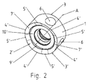
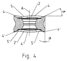
本発明による切削インサートは軸Aを備えたほぼ円筒状の基体を有する。円筒の外套面は切削インサートの逃げ面1を形成する。円筒の両蓋面はすくい面2,2’を形成する。逃げ面1とすくい面2,2’との交差部には刃先3,3’が形成される。刃先3,3’はすくい面2,2’の方向に見て正確な円形であるのに対し、逃げ面1に関して軸Aの方向に見ると全周に均等に分布されている4個の凸面状部分4,4’を有しており、これらはそれぞれ凹面状部分5,5’により互いに結合されている。逃げ面1はちょうど0°の逃げ角を有する。すくい面2,2’は刃先3,3’に直接接して25°のすくい角βを有する環状範囲7,7’を有する。この環状範囲7,7’は段9,9’を介して切削インサートの中央範囲にある平坦な窪み10,10’に移行する。
The cutting insert according to the invention has a substantially cylindrical substrate with an axis A. The outer surface of the cylinder forms the
逃げ面1の中央範囲には4個の半球状の凹み6が設けられ、これらは加工器具本体12における切削インサートのインデックスとして用いられる。相対向する刃先3,3’の4個の凸面状部分はこの場合、加工器具内において切削インサートが向きを変えられてもその都度刃先3,3’の同じ位置決めが保証されるように配置される。これは、相対向する両すくい面2,2’の刃先が軸Aに対する横軸を中心に180°互いに回転させられることにより達成される。
Four
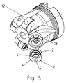
図5、図6、図7には本発明による4個の切削インサートを備えたフライス加工器具が示されている。 FIGS. 5, 6 and 7 show a milling tool with four cutting inserts according to the invention.
図5では1個の切削インサートが据付座から取り外されて示されており、少なくとも部分的に球状の表面を備えた本体12のインデックス部材13が見えている。インデックス部材13は切削インサートが締付けねじで固定されると切削インサートの半球状の凹みに食い込み、このインサートを加工器具本体の据付座に位置決めさせる。まさに切削位置にある刃先部分4,5が磨耗すると切削インサートは締付けねじを緩めて4分の1だけ回転させられ、次の磨耗してない刃先部分4,5が切削位置にくるようにされる。すくい面2の側の4個の刃先部分4,5のすべてが磨耗すると切削インサートは向きを変えられ、反対側のすくい面2’の4個の刃先部分4,5が順次使用位置にもたらされる。
In FIG. 5, one cutting insert is shown removed from the mounting seat, and the
図6には半径方向の設置角γが11°、図7には軸方向の設置角λが4°であることが示されており、この角度で各切削インサートが傾斜して加工器具本体に最適な切削に必要な切削インサートの逃げ位置を保証するように配置されていることが示されている。 FIG. 6 shows that the installation angle γ in the radial direction is 11 °, and FIG. 7 shows that the installation angle λ in the axial direction is 4 °. It is shown that it is arranged to ensure the clearance position of the cutting insert necessary for optimal cutting.
図7に示すように、切削インサートは加工器具本体において、刃先3の凸面状の曲線部分4がフライス加工器具の半径方向外側範囲に、刃先3の凹面状の曲線部分5がフライス加工器具の半径方向内側範囲にくるように配置されている。
As shown in FIG. 7, in the cutting tool body, the convex
1 逃げ面
2,2’ すくい面
3,3’ 刃先
4,4’ 凸面状曲線部分
5,5’ 凹面状曲線部分
6 半球状凹み
7,7’ 環状範囲
9,9’ 段
10,10’ 平坦状窪み
12 フライス加工器具本体
1
Claims (9)
Applications Claiming Priority (3)
| Application Number | Priority Date | Filing Date | Title |
|---|---|---|---|
| ATGM109/2011 | 2011-02-24 | ||
| ATGM109/2011U AT12527U1 (en) | 2011-02-24 | 2011-02-24 | CUTTING INSERT FOR DISCONTINUING MACHINING |
| PCT/AT2012/000041 WO2012113006A1 (en) | 2011-02-24 | 2012-02-23 | Cutting insert for machining |
Publications (2)
| Publication Number | Publication Date |
|---|---|
| JP2014509264A true JP2014509264A (en) | 2014-04-17 |
| JP2014509264A5 JP2014509264A5 (en) | 2015-01-15 |
Family
ID=46720003
Family Applications (1)
| Application Number | Title | Priority Date | Filing Date |
|---|---|---|---|
| JP2013554744A Pending JP2014509264A (en) | 2011-02-24 | 2012-02-23 | Cutting insert for cutting |
Country Status (9)
| Country | Link |
|---|---|
| US (1) | US10040138B2 (en) |
| EP (1) | EP2678128B1 (en) |
| JP (1) | JP2014509264A (en) |
| CN (1) | CN103402681B (en) |
| AT (1) | AT12527U1 (en) |
| ES (1) | ES2748033T3 (en) |
| IL (1) | IL228012B (en) |
| PL (1) | PL2678128T3 (en) |
| WO (1) | WO2012113006A1 (en) |
Cited By (1)
| Publication number | Priority date | Publication date | Assignee | Title |
|---|---|---|---|---|
| JPWO2014175322A1 (en) * | 2013-04-27 | 2017-02-23 | 京セラ株式会社 | Cutting insert, cutting tool, and method of manufacturing cut workpiece |
Families Citing this family (11)
| Publication number | Priority date | Publication date | Assignee | Title |
|---|---|---|---|---|
| SE536343C2 (en) | 2012-01-16 | 2013-09-03 | Sandvik Intellectual Property | Milling tools and double-sided indexable cutter |
| US9573203B2 (en) * | 2012-09-07 | 2017-02-21 | Sandvik Intellectual Property Ab | Milling tool as well as a milling insert therefor |
| WO2015159897A1 (en) * | 2014-04-15 | 2015-10-22 | 株式会社タンガロイ | Cutting insert, tool body, and replaceable cutting edge type rotary cutting tool |
| KR101529524B1 (en) * | 2014-08-18 | 2015-06-17 | 한국야금 주식회사 | Cutting insert and tool holder for mounting the same |
| US10183333B2 (en) * | 2016-02-03 | 2019-01-22 | Iscar, Ltd. | Circular cutting insert having non-circular peripheral edge |
| EP3351329B1 (en) * | 2017-01-18 | 2023-08-02 | Sandvik Intellectual Property AB | Indexable cutting insert for a milling tool |
| US10646927B2 (en) | 2018-02-19 | 2020-05-12 | Iscar, Ltd. | Round double-sided cutting insert having a peripheral surface provided with protruding indexing latches, insert holder therefor and cutting tool |
| EP3643439B1 (en) * | 2018-10-26 | 2022-07-13 | Seco Tools Ab | A cutting tool |
| CN113333799A (en) * | 2021-05-17 | 2021-09-03 | 贾中正 | High-efficiency cutting steel wheel rough turning circular blade with equally divided directional wavy cutting edge |
| CN114165977B (en) * | 2021-11-24 | 2024-02-06 | 安徽康佳同创电器有限公司 | Drawer with limiting structure |
| CN114226819A (en) * | 2022-01-12 | 2022-03-25 | 百斯图工具制造有限公司 | Anti-rotation universal circular milling blade |
Citations (4)
| Publication number | Priority date | Publication date | Assignee | Title |
|---|---|---|---|---|
| JPS57126904U (en) * | 1981-01-29 | 1982-08-07 | ||
| DE102008037915B3 (en) * | 2008-08-14 | 2009-08-13 | Kennametal Inc. | Indexable insert |
| US20090290946A1 (en) * | 2006-05-18 | 2009-11-26 | Zastrozynski Jurgen | Cutting insert for machining a workpiece |
| WO2010023659A1 (en) * | 2008-08-31 | 2010-03-04 | Iscar Ltd. | Cutting tool and round double sided cutting insert therefor |
Family Cites Families (9)
| Publication number | Priority date | Publication date | Assignee | Title |
|---|---|---|---|---|
| JPS57126904A (en) | 1981-01-30 | 1982-08-06 | Sumitomo Metal Ind Ltd | Control method for air-permeability of blast furnace |
| JPH1119817A (en) * | 1997-05-02 | 1999-01-26 | Synx Kk | Throwaway type scallop cutter |
| IL145574A0 (en) | 2001-09-24 | 2002-06-30 | Iscar Ltd | Cutting tool and cutting insert therefor |
| US7722297B2 (en) * | 2003-04-15 | 2010-05-25 | Tdy Industries, Inc. | Antirotation tool holder and cutting insert |
| DE102006025293C5 (en) * | 2006-05-31 | 2010-12-23 | Kennametal Inc. | Method of machining a wheel |
| IL182343A0 (en) * | 2007-04-01 | 2007-07-24 | Iscar Ltd | Cutting insert and tool for milling and ramping at high feed rates |
| WO2010110009A1 (en) | 2009-03-24 | 2010-09-30 | 日立ツール株式会社 | Cutting tip replacement type rotary tool |
| KR101103216B1 (en) * | 2009-05-19 | 2012-01-05 | 대구텍 유한회사 | Double-sided cutting insert having a circular shape and cutting tool using the same |
| US8573903B2 (en) * | 2009-11-03 | 2013-11-05 | Kennametal Inc. | Round cutting insert with anti-rotation feature |
-
2011
- 2011-02-24 AT ATGM109/2011U patent/AT12527U1/en not_active IP Right Cessation
-
2012
- 2012-02-23 ES ES12712531T patent/ES2748033T3/en active Active
- 2012-02-23 US US14/001,534 patent/US10040138B2/en active Active
- 2012-02-23 JP JP2013554744A patent/JP2014509264A/en active Pending
- 2012-02-23 EP EP12712531.8A patent/EP2678128B1/en active Active
- 2012-02-23 PL PL12712531T patent/PL2678128T3/en unknown
- 2012-02-23 CN CN201280010500.2A patent/CN103402681B/en active Active
- 2012-02-23 WO PCT/AT2012/000041 patent/WO2012113006A1/en active Application Filing
-
2013
- 2013-08-18 IL IL228012A patent/IL228012B/en active IP Right Grant
Patent Citations (4)
| Publication number | Priority date | Publication date | Assignee | Title |
|---|---|---|---|---|
| JPS57126904U (en) * | 1981-01-29 | 1982-08-07 | ||
| US20090290946A1 (en) * | 2006-05-18 | 2009-11-26 | Zastrozynski Jurgen | Cutting insert for machining a workpiece |
| DE102008037915B3 (en) * | 2008-08-14 | 2009-08-13 | Kennametal Inc. | Indexable insert |
| WO2010023659A1 (en) * | 2008-08-31 | 2010-03-04 | Iscar Ltd. | Cutting tool and round double sided cutting insert therefor |
Cited By (1)
| Publication number | Priority date | Publication date | Assignee | Title |
|---|---|---|---|---|
| JPWO2014175322A1 (en) * | 2013-04-27 | 2017-02-23 | 京セラ株式会社 | Cutting insert, cutting tool, and method of manufacturing cut workpiece |
Also Published As
| Publication number | Publication date |
|---|---|
| CN103402681A (en) | 2013-11-20 |
| WO2012113006A1 (en) | 2012-08-30 |
| US10040138B2 (en) | 2018-08-07 |
| EP2678128B1 (en) | 2019-07-10 |
| IL228012A0 (en) | 2013-09-30 |
| AT12527U1 (en) | 2012-07-15 |
| US20130330135A1 (en) | 2013-12-12 |
| CN103402681B (en) | 2016-06-08 |
| IL228012B (en) | 2018-08-30 |
| PL2678128T3 (en) | 2020-01-31 |
| EP2678128A1 (en) | 2014-01-01 |
| ES2748033T3 (en) | 2020-03-12 |
Similar Documents
| Publication | Publication Date | Title |
|---|---|---|
| JP2014509264A (en) | Cutting insert for cutting | |
| JP6178078B2 (en) | Milling tools and milling inserts | |
| US9233426B2 (en) | Octagonal cutting insert having edge portion with variable wedge angle, and cutting tool | |
| JP6580572B2 (en) | Indexable double-sided cutting insert and cutting tool therefor | |
| JP5992839B2 (en) | Milling tools and milling inserts | |
| RU2426917C2 (en) | Screw with flat head | |
| JP2013022727A (en) | Cutting insert especially for tooth cutter | |
| CN102626794B (en) | Process tool | |
| KR20100090277A (en) | Tangential cutting insert | |
| JPWO2015163326A1 (en) | Cutting inserts and cutting tools | |
| JP6078632B2 (en) | Left-handed and right-handed cutting tools | |
| KR102007596B1 (en) | Insertion Tool and Thread Mill | |
| JP2010089250A (en) | Cutting insert and insert removable rotary cutting tool | |
| JP2014509264A5 (en) | ||
| JP4650272B2 (en) | Round piece insert removable luffing end mill | |
| JP5835337B2 (en) | Cutting inserts and cutting tools | |
| JP2021513921A (en) | Circular double-sided cutting inserts with a peripheral surface with a protruding index latch, insert holders for cutting inserts, and cutting tools | |
| JP6612152B2 (en) | Cutting inserts and cutting tools | |
| WO2017002596A1 (en) | Dual-surface circular cutting insert and blade edge-exchangeable rotating cutting tool | |
| JP5185322B2 (en) | Cutting tools | |
| JP7432611B2 (en) | Round cutting inserts for milling tools | |
| KR20190095260A (en) | Milling tools and manufacturing methods for milling tools | |
| JP6197958B2 (en) | Cutting insert and cutting edge changeable cutting tool | |
| JP2020533186A (en) | Cutting inserts and crankshaft milling tools | |
| JP2020504025A (en) | Indexable cutting inserts for milling tools |
Legal Events
| Date | Code | Title | Description |
|---|---|---|---|
| A521 | Request for written amendment filed |
Free format text: JAPANESE INTERMEDIATE CODE: A523 Effective date: 20141118 |
|
| A621 | Written request for application examination |
Free format text: JAPANESE INTERMEDIATE CODE: A621 Effective date: 20141118 |
|
| A977 | Report on retrieval |
Free format text: JAPANESE INTERMEDIATE CODE: A971007 Effective date: 20151021 |
|
| A131 | Notification of reasons for refusal |
Free format text: JAPANESE INTERMEDIATE CODE: A131 Effective date: 20151117 |
|
| A521 | Request for written amendment filed |
Free format text: JAPANESE INTERMEDIATE CODE: A523 Effective date: 20160210 |
|
| A02 | Decision of refusal |
Free format text: JAPANESE INTERMEDIATE CODE: A02 Effective date: 20160329 |