JP2014507847A - Method and apparatus for signal transmission for multi-antenna transmission using precoding - Google Patents
Method and apparatus for signal transmission for multi-antenna transmission using precoding Download PDFInfo
- Publication number
- JP2014507847A JP2014507847A JP2013548441A JP2013548441A JP2014507847A JP 2014507847 A JP2014507847 A JP 2014507847A JP 2013548441 A JP2013548441 A JP 2013548441A JP 2013548441 A JP2013548441 A JP 2013548441A JP 2014507847 A JP2014507847 A JP 2014507847A
- Authority
- JP
- Japan
- Prior art keywords
- phase
- sequence
- signaling bits
- signaling
- wtru
- Prior art date
- Legal status (The legal status is an assumption and is not a legal conclusion. Google has not performed a legal analysis and makes no representation as to the accuracy of the status listed.)
- Pending
Links
Images


Classifications
-
- H—ELECTRICITY
- H04—ELECTRIC COMMUNICATION TECHNIQUE
- H04L—TRANSMISSION OF DIGITAL INFORMATION, e.g. TELEGRAPHIC COMMUNICATION
- H04L1/00—Arrangements for detecting or preventing errors in the information received
- H04L1/02—Arrangements for detecting or preventing errors in the information received by diversity reception
- H04L1/06—Arrangements for detecting or preventing errors in the information received by diversity reception using space diversity
-
- H—ELECTRICITY
- H04—ELECTRIC COMMUNICATION TECHNIQUE
- H04B—TRANSMISSION
- H04B7/00—Radio transmission systems, i.e. using radiation field
- H04B7/02—Diversity systems; Multi-antenna system, i.e. transmission or reception using multiple antennas
- H04B7/04—Diversity systems; Multi-antenna system, i.e. transmission or reception using multiple antennas using two or more spaced independent antennas
- H04B7/0413—MIMO systems
- H04B7/0417—Feedback systems
-
- H—ELECTRICITY
- H04—ELECTRIC COMMUNICATION TECHNIQUE
- H04B—TRANSMISSION
- H04B7/00—Radio transmission systems, i.e. using radiation field
- H04B7/02—Diversity systems; Multi-antenna system, i.e. transmission or reception using multiple antennas
- H04B7/04—Diversity systems; Multi-antenna system, i.e. transmission or reception using multiple antennas using two or more spaced independent antennas
- H04B7/0404—Diversity systems; Multi-antenna system, i.e. transmission or reception using multiple antennas using two or more spaced independent antennas the mobile station comprising multiple antennas, e.g. to provide uplink diversity
-
- H—ELECTRICITY
- H04—ELECTRIC COMMUNICATION TECHNIQUE
- H04B—TRANSMISSION
- H04B7/00—Radio transmission systems, i.e. using radiation field
- H04B7/02—Diversity systems; Multi-antenna system, i.e. transmission or reception using multiple antennas
- H04B7/04—Diversity systems; Multi-antenna system, i.e. transmission or reception using multiple antennas using two or more spaced independent antennas
- H04B7/0413—MIMO systems
- H04B7/0456—Selection of precoding matrices or codebooks, e.g. using matrices antenna weighting
-
- H—ELECTRICITY
- H04—ELECTRIC COMMUNICATION TECHNIQUE
- H04B—TRANSMISSION
- H04B7/00—Radio transmission systems, i.e. using radiation field
- H04B7/02—Diversity systems; Multi-antenna system, i.e. transmission or reception using multiple antennas
- H04B7/04—Diversity systems; Multi-antenna system, i.e. transmission or reception using multiple antennas using two or more spaced independent antennas
- H04B7/06—Diversity systems; Multi-antenna system, i.e. transmission or reception using multiple antennas using two or more spaced independent antennas at the transmitting station
- H04B7/0613—Diversity systems; Multi-antenna system, i.e. transmission or reception using multiple antennas using two or more spaced independent antennas at the transmitting station using simultaneous transmission
- H04B7/0615—Diversity systems; Multi-antenna system, i.e. transmission or reception using multiple antennas using two or more spaced independent antennas at the transmitting station using simultaneous transmission of weighted versions of same signal
- H04B7/0619—Diversity systems; Multi-antenna system, i.e. transmission or reception using multiple antennas using two or more spaced independent antennas at the transmitting station using simultaneous transmission of weighted versions of same signal using feedback from receiving side
- H04B7/0636—Feedback format
- H04B7/0641—Differential feedback
-
- H—ELECTRICITY
- H04—ELECTRIC COMMUNICATION TECHNIQUE
- H04L—TRANSMISSION OF DIGITAL INFORMATION, e.g. TELEGRAPHIC COMMUNICATION
- H04L27/00—Modulated-carrier systems
- H04L27/26—Systems using multi-frequency codes
Abstract
プリコーディングを用いたマルチアンテナ送信のための信号伝達の方法および装置を開示する。大きな差を有するプリコーダの位相が、大きいハミング距離を有するビットシーケンスを用いて信号伝達されるという点で、プリコーダの位相情報は、エラー許容範囲の程度を与えるビットシーケンスを用いて信号伝達することができる。方法は、無線送受信ユニット(WTRU)において、所望のプリコーダ位相値に対応する信号伝達ビットのシーケンスを表すプリコーディングインジケータ信号を受信するステップと、信号伝達ビットのシーケンスを複数の所定の信号伝達ビットのシーケンスと比較することによって、所望のプリコーダ位相値を取得するステップであって、所定の信号伝達シーケンスのペアは、互いに反対であり、180度異なるプリコーダ位相値に対応する所望のプリコーダ位相値を取得するステップと、複数のアンテナを介して送信されるWTRUのアップリンク信号のストリームに重み値のセットを追加するステップであって、重み値のセットは、所望のプリコーダ位相値に等しい位相差を有する、重み値のセットを追加するステップとを含む。A signaling method and apparatus for multi-antenna transmission using precoding is disclosed. The precoder phase information can be signaled using a bit sequence that gives a degree of error tolerance in that the phase of the precoder having a large difference is signaled using a bit sequence having a large Hamming distance. it can. The method includes receiving, at a wireless transmit / receive unit (WTRU), a precoding indicator signal representing a sequence of signaling bits corresponding to a desired precoder phase value, and converting the sequence of signaling bits to a plurality of predetermined signaling bits. Obtaining a desired precoder phase value by comparing with a sequence, wherein a predetermined pair of signaling sequences are opposite to each other and corresponding to a precoder phase value 180 degrees different And adding a set of weight values to the WTRU uplink signal stream transmitted via the plurality of antennas, the set of weight values having a phase difference equal to a desired precoder phase value Adding a set of weight values.
Description
本発明は、プリコーディングを用いたマルチアンテナ送信のための信号伝達の方法および装置に関する。 The present invention relates to a signal transmission method and apparatus for multi-antenna transmission using precoding.
本出願は、(i)2011年1月7日に出願した、「A METHOD FOR MULTI-MEDIA TRANSMISSION SCHEMES WITH PRECODING」(代理人参照番号、IDC−10886US01)という名称の米国(「US」)特許仮出願第(「特許仮出願第」)61/430,756号明細書、(ii)2011年2月11日に出願した、「A METHOD FOR MULTI-ANTENNA TRANSMISSION SCHEMES WITH PRECODING」(代理人参照番号、IDC−10914US01)という名称のUS特許仮出願第61/441,770号明細書、(iii)2011年4月29日に出願した、「METHOD AND APPARATUS FOR SIGNALING FOR MULTI-ANTENNA TRANSMISSION WITH PRECODING」(代理人参照番号、IDC−11030US01)という名称の米国特許仮出願第61/481,070号明細書、および(iv)2011年8月11日に出願した、「METHOD AND APPARATUS FOR SIGNALING FOR MULTI-ANTENNA TRANSMISSION WITH PRECODFNG」(代理人参照番号、IDC−11108US01)という名称の米国特許仮出願第61/522,454号明細書の利益を主張するものであり、これらの出願のそれぞれは、参照により本明細書に組み込まれる。 This application is based on (i) a US (“US”) patent provisional application entitled “A METHOD FOR MULTI-MEDIA TRANSMISSION SCHEMES WITH PRECODING” (Attorney Reference Number, IDC-10886 US01) filed on January 7, 2011. Application No. (“Patent Provisional Application”) 61 / 430,756, (ii) “A METHOD FOR MULTI-ANTENNA TRANSMISSION SCHEMES WITH PRECODING” filed on February 11, 2011 (agent reference number, US Patent Provisional Application No. 61 / 441,770 (IDC-10914US01), (iii) "METHOD AND APPARATUS FOR SIGNALING FOR MULTI-ANTENNA TRANSMISSION WITH PRECODING" filed on April 29, 2011 (agent) U.S. Provisional Application No. 61 / 481,070, named Human Reference Number, IDC-11030US01), and (iv) filed on August 11, 2011, “ Claims the benefit of US Provisional Application No. 61 / 522,454, entitled “METHOD AND APPARATUS FOR SIGNALING FOR MULTI-ANTENNA TRANSMISSION WITH PRECODFNG” (agent reference number, IDC-11108US01). Each of the applications is incorporated herein by reference.
新式の信号処理アルゴリズムを用いたマルチアンテナ送受信技法は、多入力多出力(MIMO)技術と呼ばれる場合もある。MIMOは、複数の情報ストリームが同時に送信されるプリコーディングされた空間多重化を含み得る。空間多重化は、チャネル状態が空間多重化にとって好ましくないときにカバレッジ(coverage)を増大させるために、ビームフォーミング(beamforming)または送信ダイバーシチで増強することができる。チャネルに依存するプリコーディングについては、典型的には、受信機におけるパワーを最大化する「方向」に送信を分散させるように重みが選択される。 Multi-antenna transmission / reception techniques using new signal processing algorithms are sometimes referred to as multiple-input multiple-output (MIMO) techniques. MIMO may include precoded spatial multiplexing in which multiple information streams are transmitted simultaneously. Spatial multiplexing can be enhanced with beamforming or transmit diversity to increase coverage when channel conditions are undesirable for spatial multiplexing. For channel dependent precoding, weights are typically selected to distribute the transmission in a “direction” that maximizes power at the receiver.
プリコーディングを用いたマルチアンテナ送信のための信号伝達の方法および装置を開示する。位相情報は、シンボルのエラーの影響を抑えるシンボルマッピングを用いて信号伝達することができる。一方法では、無線送受信ユニット(WTRU)は、所望のプリコーダの位相の値(以下、プリコーダ位相値)に対応する信号伝達ビットのシーケンスを表すプリコーディングインジケータ信号(以下、プリコーディングインジケータ信号)を受信する。このWTRUは、信号伝達ビットのシーケンスを複数の所定の信号伝達ビットのシーケンスと比較することによって、所望のプリコーダ位相値を得る。所定の信号伝達ビットのシーケンスのペアは、互いに反対であるように構成され、180度に設定され得る最大の増分だけ異なるプリコーダ位相値に対応するようにマッピングすることができる。WTRUは、複数のアンテナを介して送信されるWTRUのアップリンク信号のストリームに重み値のセットを加え、重み値のセットは所望のプリコーダ位相値に等しい位相差を有する。プリコーディングインジケータ信号は、広帯域符号分割多重アクセス方式のダウンリンク信号送信の部分チャネルで運ぶことができる。信号伝達ビットのシーケンスは、長さが2つの情報ビットに相当し、2つの情報ビットは、BPSK変調が使用される場合、2つのデータビットとして表わされ、またはQPSK変調が使用される場合、4つのデータビットとして表わされ得る。 A signaling method and apparatus for multi-antenna transmission using precoding is disclosed. The phase information can be signaled using symbol mapping that reduces the effects of symbol errors. In one method, a wireless transmit / receive unit (WTRU) receives a precoding indicator signal (hereinafter precoding indicator signal) that represents a sequence of signaling bits corresponding to a desired precoder phase value (hereinafter precoder phase value). To do. The WTRU obtains a desired precoder phase value by comparing a sequence of signaling bits with a plurality of predetermined sequences of signaling bits. Predetermined signaling bit pairs are configured to be opposite to each other and can be mapped to correspond to different precoder phase values by a maximum increment that can be set to 180 degrees. The WTRU adds a set of weight values to the WTRU's uplink signal stream transmitted via multiple antennas, the set of weight values having a phase difference equal to the desired precoder phase value. The precoding indicator signal can be carried on a partial channel of downlink signal transmission of a wideband code division multiple access scheme. The sequence of signaling bits corresponds to two information bits in length, which are represented as two data bits if BPSK modulation is used, or if QPSK modulation is used, It can be represented as 4 data bits.
振幅情報は、多入力/多出力の閉ループの送信ダイバーシチのために、位相情報とは異なる速度で信号伝達されてもよい。ダウンリンク信号伝達、アップリンク信号伝達、またはその両方が使用され得る。出力制御が、非プリコーディング個別物理制御チャネル(non−precoded Dedicated Physical Control Channel)のために実施され得る。 The amplitude information may be signaled at a different speed than the phase information for multi-input / multi-output closed-loop transmit diversity. Downlink signaling, uplink signaling, or both can be used. Power control may be implemented for non-precoded Dedicated Physical Control Channel.
より詳細な理解は、添付図面と併せて例によって与えられる後続の説明から得ることができる。
図1Aは、1つまたは複数の開示された実施形態が実施可能である通信システム100の一例の図である。通信システム100は、複数の無線ユーザに音声、データ、映像、メッセージ通信、放送等などのコンテンツを送るマルチプルアクセスシステム(multiple access system)であり得る。通信システム100は、複数の無線ユーザが、無線帯域幅を含むシステムリソースの共有によってそのようなコンテンツにアクセスすることを可能にすることができる。例えば、通信システム100は、符号分割多重接続(CDMA)、時分割多重接続(TDMA)、周波数分割多重接続(FDMA)、直交FDMA(OFDMA)、シングルキャリアFDMA(SC−FDMA)等などの1つまたは複数のチャネルにアクセスする方法を用いることができる。
FIG. 1A is an illustration of an
図1Aに示すように、通信システム100は、無線送受信ユニット(WTRU)102a、102b、102c、102dと、無線アクセスネットワーク(RAN)104と、コアネットワーク106と、公衆交換電話網(PSTN)108と、インターネット110と、他のネットワーク112とを含み得るが、開示された実施形態は、任意の個数のWTRU、基地局、ネットワーク、および/またはネットワーク要素を予想することが理解されよう。WTRU102a、102b、102c、102dの各々は、無線環境中で動作および/または通信するように構成される任意のタイプのデバイスであり得る。例として、WTRU102a、102b、102c、102dは、無線信号を送信および/または受信するように構成することができ、ユーザ機器(UE)、移動局、固定または移動式の加入者ユニット、紙ポケベル、携帯電話、携帯情報端末(PDA)、スマートフォン、ラップトップ、ネットブック、パーソナルコンピュータ、無線センサ、家庭用電化製品などが含まれ得る。
As shown in FIG. 1A, a
通信システム100は、基地局114aおよび基地局114bを含むこともできる。基地局114a、114bの各々は、コアネットワーク106、インターネット110、および/またはネットワーク112などの1つまたは複数の通信ネットワークにアクセスするのを助けるために、WTRU102a、102b、102c、102dのうちの少なくとも1つと無線で接続するように構成される任意のタイプのデバイスであり得る。例として、基地局114a、114bは、ベーストランシーバ基地局(BTS)、NodeB、eNodeB、Home NodeB、Home eNodeB、サイトコントローラ(site controller)、アクセスポイント(AP)、無線ルータ(wireless router)などであり得る。基地局114a、114bは、単一の要素としてそれぞれ示されるが、基地局114a、114bは、任意の個数の相互接続された基地局および/またはネットワーク要素を含んでもよいことが理解されよう。
The
基地局114aは、RAN104の一部であってもよく、RAN104は、他の基地局、および/または基地局コントローラ(BSC)、無線ネットワークコントローラ(RNC)、中継ノード等などネットワーク要素(図示せず)を含むこともできる。基地局114aおよび/または基地局114bは、セル(図示せず)と呼ばれる場合もある特定の地理的地域内で、無線信号を送信および/または受信するように構成されてもよい。セルは、セルセクタ(cell sector)にさらに分割されてもよい。例えば、基地局114aに関連したセルは、3つのセクタに分割されてもよい。したがって、一実施形態では、基地局114aは、3つの送受信機、すなわち、セルのセクタごとに1つを含んでもよい。別の実施形態では、基地局114aは、多重入出力(MIMO)技術を用いることができ、したがって、セルのセクタごとに複数の送受信機を利用することができる。
The
基地局114a、114bは、任意の適切な無線通信リンク(例えば、高周波(RF)、マイクロ波、赤外線(IR)、紫外線(UV)、可視光など)であり得るエアインタフェース116を介して、WTRU102a、102b、102c、102dの1つまたは複数と通信することができる。エアインタフェース116は、任意の適切な無線アクセス技術(RAT)を用いて確立することができる。
より具体的には、上述のように、通信システム100は、マルチプルアクセスシステムであってもよく、CDMA、TDMA、FDMA、OFDMA、SC−FDMA等などの1つまたは複数のチャネルアクセス方式を用いることができる。例えば、RAN104における基地局114a、およびWTRU102a、102b、102cは、ユニバーサル移動体通信システム(UMTS)地上無線アクセス(UTRA)などの無線技術を実施することができ、これは、広帯域CDMA(WCDMA(登録商標))を用いてエアインタフェース116を確立することができる。WCDMAは、高速パケットアクセス(HSPA)、および/または進化型HSPA(Evolved HSPA)(HSPA+)などの通信プロトコルを含むことができる。HSPAには、高速ダウンリンクパケットアクセス(HSDPA)、および/または高速アップリンクパケットアクセス(HSUPA)が含まれ得る。
More specifically, as described above, the
別の実施形態では、基地局114a、およびWTRU102a、102b、102cは、進化型UMTS地上無線アクセス(E−UTRA)などの無線技術を実施することができ、これは、LTE(Long Term Evolution)を確立することができる、および/またはLTE−Advanced(LTE−A)を用いてエアインタフェース116を確立することができる。
In another embodiment, the
他の実施形態では、基地局114a、およびWTRU102a、102b、102cは、IEEE802.16(すなわち、WiMAX(Worldwide Interoperability for Microwave Access))、CDMA2000、CDMA2000 IX、CDMA2000 EV−DO、IS−2000(Interim Standard 2000)、IS−95(Interim Standard 95)、IS−856(Interim Standard 856)、GSM(登録商標)(Global System for Mobile communications)、GSM進化型高速データレート(EDGE)、GSM EDGE(GERAN)等などの無線技術を実施することができる。
In other embodiments, the
図1A中の基地局114bは、例えば、無線ルータ、Home NodeB、Home eNodeB、またはアクセスポイントであってもよく、ビジネス、家庭、車両、キャンパス等の場所などの局所の範囲内での無線接続性を助けるために任意の適切なRATを利用してもよい。一実施形態では、基地局114b、およびWTRU102c、102dは、IEEE802.11などの無線技術を実施して、無線LAN(WLAN:wireless local area network)を確立することができる。別の実施形態では、基地局114b、およびWTRU102c、102dは、IEEE802.15などの無線技術を実施して、無線パーソナルエリアネットワーク(WPAN)を確立することができる。さらに別の実施形態では、基地局114b、およびWTRU102c、102dは、携帯電話ベースのRAT(例えば、WCDMA、CDMA2000、GSM、LTE、LTE−Aなど)を利用して、ピコセルまたはフェムトセルを確立することができる。図1Aに示すように、基地局114bは、インターネット110への直接接続を有してもよい。したがって、基地局114bは、コアネットワーク106を介してインターネット110にアクセスしなくてもよい。
The
RAN104は、コアネットワーク106と通信することができ、コアネットワーク106は、インターネットプロトコル(VoIP)サービスを介してWTRU102a、102b、102c、102dの1つまたは複数に音声、データ、アプリケーション、および/または音声を提供するように構成される任意のタイプのネットワークであり得る。例えば、コアネットワーク106は、呼制御、請求処理サービス、モバイルロケーションベースのサービス(mobile location−based)、プリペイド式通話、インターネット接続性、映像分配などを提供することができ、および/またはユーザの認証などの高レベルのセキュリティ機能を実行することができる。図1Aに示されていないが、RAN104および/またはコアネットワーク106は、RAN104と同じRATまたは異なるRATを用いる他のRANと直接または間接的に通信することができることが理解されよう。例えば、E−UTRA無線技術を利用できるRAN104に接続されることに加えて、コアネットワーク106は、GSM無線技術を用いる別のRAN(図示せず)と通信することもできる。
The
コアネットワーク106は、PSTN108、インターネット110、および/または他のネットワーク112にアクセスするために、WTRU102a、102b、102c、102dのためのゲートウェイとしての役割を果たすこともできる。PSTN108は、基本的な電話サービス(POTS:plain old telephone service)を提供する回線交換電話網を含んでもよい。インターネット110は、共通の通信プロトコル、例えば、TCP/IPインターネットプロトコル一式におけるTCP(transmission control protocol)、ユーザデータグラムプロトコル(UDP)、およびインターネットプロトコル(IP)などを使用する相互接続されたコンピュータネットおよびデバイスの地球規模のシステムを含んでもよい。ネットワーク112は、他のサービスプロバイダによって所有および/または動作される有線または無線の通信ネットワークを含んでもよい。例えば、ネットワーク112は、RAN104と同じRATまたは異なるRATを用い得る1つまたは複数のRANに接続された別のコアネットワークを含んでもよい。
The
通信システム100におけるWTRU102a、102b、102c、102dの一部または全部は、マルチモードの機能を含んでもよく、すなわち、WTRU102a、102b、102c、102dは、異なる無線リンクを介して異なる無線ネットワークと通信するための複数の送受信機を含んでもよい。例えば、図1Aに示すWTRU102cは、携帯電話ベースの無線技術を用いることができる基地局114a、およびIEEE802無線技術を用いることができる基地局114bと通信するように構成されてもよい。
Some or all of the
図1Bは、WTRU102の一例の系統図である。図1Bに示すように、WTRU102は、プロセッサ118と、送受信機120と、送受信要素122と、スピーカ/マイクロフォン124と、キーパッド126と、ディスプレイ/タッチパッド128と、非着脱式メモリ130と、着脱式メモリ132と、電源134と、GPS(global positioning system)チップセット136と、他の周辺機器138とを含むことができる。WTRU102は、実施形態と一致したままでありつつ前述の要素の任意のサブコンビネーションを含んでもよいことが理解されよう。
FIG. 1B is a system diagram of an example of a
プロセッサ118は、汎用のプロセッサ、専用のプロセッサ、従来のプロセッサ、デジタル信号プロセッサ(DSP)、複数のマイクロプロセッサ、DSPコアに関連した1つまたは複数のマイクロプロセッサ、コントローラ、マイクロコントローラ、特定用途向け集積回路(ASIC)、フィールドプログラマブルゲートアレイ(FPGA)回路、任意の他のタイプの集積回路(IC)、状態機械などであってもよい。プロセッサ118は、信号コーディング、データ処理、出力制御、入出力処理、および/またはWTRU102が無線環境中で動作することを可能にする任意の他の機能を実行することができる。プロセッサ118は送受信機120に結合されてもよく、送受信機120は送受信要素122に結合されてもよい。図1Bが、プロセッサ118および送受信機120を別個の構成要素として示す一方、プロセッサ118および送受信機120は、電子パッケージまたはチップ中に共に一体化されてもよいことが理解されよう。
The
送受信要素122は、エアインタフェース116を介して基地局(例えば、基地局114a)へ信号を送信する、または基地局(例えば、基地局114a)から信号を受信するように構成されてもよい。例えば、一実施形態では、送受信要素122は、RF信号を送信および/または受信するように構成されるアンテナであってもよい。別の実施形態では、送受信要素122は、例えば、IR、UVまたは可視光の信号を送信および/または受信するように構成される放射体/検出器であってもよい。さらに別の実施形態では、送受信要素122は、RF信号と光信号の両方を送受信するように構成されてもよい。送受信要素122は、無線信号の任意の組み合わせを送信および/または受信するように構成することができることが理解されよう。
The transmit / receive
加えて、図1Bでは、送受信要素122は単一の要素として示されるが、WTRU102は、任意の個数の送受信要素122を含んでもよい。より具体的には、WTRU102は、MIMO技術を用いてもよい。したがって、一実施形態では、WTRU102は、エアインタフェース116を介して無線信号を送受信するために2つ以上の送受信要素122(例えば、複数のアンテナ)を備えてもよい。
In addition, in FIG. 1B, the transmit / receive
送受信機120は、受信要素122によって送信されることになる信号を変調し、送受信要素122によって受信される信号を復調するように構成することができる。上述のように、WTRU102は、マルチモードの機能を有することができる。したがって、送受信機120は、例えば、UTRAおよびIEEE802.11などの複数のRATを介してWTRU102が通信することを可能にするために複数の送受信機を備えてもよい。
The
WTRU102のプロセッサ118は、スピーカ/マイクロフォン124、キーパッド126、および/またはディスプレイ/タッチパッド128(例えば、液晶ディスプレイ(LCD)表示装置、または有機発光ダイオード(OLED)表示装置)に結合することができ、ピーカ/マイクロフォン124、キーパッド126、および/またはディスプレイ/タッチパッド128(例えば、液晶ディスプレイ(LCD)表示装置、または有機発光ダイオード(OLED)表示装置)からユーザが入力したデータを受信することができる。プロセッサ118は、ユーザのデータをスピーカ/マイクロフォン124、キーパッド126、および/またはディスプレイ/タッチパッド128に出力することもできる。加えて、プロセッサ118は、非着脱式メモリ106および/または着脱式メモリ132などの任意のタイプの適切なメモリから情報にアクセスし、非着脱式メモリ106および/または着脱式メモリ132などの任意のタイプの適切なメモリにデータを記憶することができる。非着脱式メモリ106は、RAM(random−access memory)、ROM(readonly memory)、ハードディスク、または任意の他のタイプのメモリ記憶装置デバイスを含んでもよい。着脱式メモリ132には、加入者を識別するモジュール(SIM)カード、メモリスティック、セキュアデジタル(SD:secure digital)メモリカードなどが含まれ得る。他の実施形態では、プロセッサ118は、サーバまたは家庭用コンピュータ(図示せず)上などのWTRU102上に物理的に位置しないメモリから情報にアクセスし、このメモリにデータを記憶することができる。
The
プロセッサ118は、電源134から電力を受け取ることができ、WTRU102中の他の構成要素へ電力を分配しおよび/またはWTRU102中の他の構成要素へ電力を制御するように構成することができる。電源134は、WTRU102に電力を供給するための任意の適切なデバイスであればよい。例えば、電源134には、1つまたは複数の乾電池(例えば、ニッケルカドミウム(NiCd)、ニッケル亜鉛(NiZn)、ニッケル水素(NiMH)、リチウムイオン(Li−ion)など)、太陽電池、燃料電池などが含まれ得る。
The
プロセッサ118は、GPSチップセット136に結合することもでき、GPSチップセット136は、WTRU102の現在位置に関係する位置情報(例えば、経度および緯度)を与えるように構成されてもよい。GPSチップセット136からの情報に加えて、またはその情報に代えて、WTRU102は、エアインタフェース116を介して基地局(例えば、基地局114a、114b)から位置情報を受信することができ、および/または2つ以上のすぐ近くの基地局から受信される信号のタイミングに基づいてその位置を決定する。WTRU102は、実施形態と一致したままでありつつ、任意の適切な位置決定方法によって位置情報を取得することができることが理解されよう。
The
プロセッサ118は、他の周辺機器138にさらに結合されてもよく、これは追加の特徴、機能性および/または有線接続性もしくは無線接続性を与える1つまたは複数のソフトウェアおよび/またはハードウェアのモジュールを含み得る。例えば、周辺機器138には、速度計、イーコンパス(e−compass)、衛星送受信機、(写真または映像用の)デジタルカメラ、USB(universal serial bus)ポート、振動デバイス、テレビの送受信機、ハンドフリーのヘッドセット、Bluetooth(登録商標)モジュール、周波数変調(FM)式の無線装置、デジタル音楽プレイヤ、メディアプレイヤ、ビデオゲームプレイヤーのモジュール、インターネットのブラウザなどが含まれ得る。
The
図1Cは、一実施形態によるRAN104およびコアネットワーク106の系統図である。上述のように、RAN104は、UTRA無線技術を用いて、エアインタフェース116を介してWTRU102a、102b、102cと通信することができる。RAN104は、コアネットワーク106と通信することもできる。図1Cに示すように、RAN104は、NodeB140a、140b、140cを含むことができ、NodeB140a、140b、140cは、エアインタフェース116を介してWTRU102a、102b、102cと通信するために1つまたは複数の送受信機をそれぞれ含むことができる。NodeB140a、140b、140cは、RAN104内の特定のセル(図示せず)とそれぞれ関連することができる。RAN104は、RNC142a、142bを含むこともできる。RAN104は、実施形態と一致したままでありつつ、任意の個数のNodeBおよびRNCを含んでもよいことが理解されよう。
FIG. 1C is a system diagram of the
図1Cに示すように、NodeB140a、140bは、RNC142aと通信することができる。加えて、NodeB140cは、RNC142bと通信することができる。NodeBs140a、140b、140cは、Iubインタフェースを介してそれぞれのRNC142a、142bと通信することができる。RNC142a、142bは、Iurインタフェースを介して互いに通信することができる。RNC142a、142bの各々は、そこに接続されるそれぞれのNodeB140a、140b、140cを制御するように構成することができる。加えて、RNC142a、142bの各々は、他の機能性、例えば、外部ループ電力制御、負荷制御、流入制御、パケットスケジューリング(packet scheduling)、ハンドオーバ制御、マクロダイバーシチ(macrodiversity)、セキュリティ機能、データの暗号化などを実行または支援するように構成することができる。
As shown in FIG. 1C, the
図1Cに示すコアネットワーク106には、メディアゲートウェイ(MGW)144、モバイル交換局(MSC)146、サービス提供サポートノード(SGSN)148、および/またはゲートウェイGPRSサポートノード(CGSN)150が含まれ得る。前述の要素の各々は、コアネットワーク106の一部として示されるが、これらの要素のうちのいずれか1つが、コアネットワークのオペレータ以外のエンティティ(entity)によって所有および/または動作されてもよいことが理解されよう。
The
RAN104中のRNC142aは、IuCSインタフェースを介してコアネットワーク106中のMSC146に接続することができる。MSC146は、MGW144に接続することができる。MSC146およびMGW144は、WTRU102a、102b、102cと従来の地上通信線通信デバイスの間の通信を助けるために、WTRU102a、102b、102cにPSTN108などの回線交換ネットワークへのアクセスを提供することができる。
The
RAN104中のRNC142aは、IuPSインタフェースを介してコアネットワーク106中のSGSN148に接続することもできる。SGSN148は、CGSN150に接続することができる。SGSN148およびCGSN150は、WTRU102a、102b、102cとIPイネーブルデバイス(IP−enabled devices)との間の通信を助けるために、WTRU102a、102b、102cにインターネット110などのパケット交換ネットワークへのアクセスを提供することができる。
The
上述のように、コアネットワーク106は、ネットワーク112に接続することもでき、ネットワーク112は、他のサービスプロバイダによって所有および/または運営される他の有線または無線のネットワークを含んでもよい。
As described above, the
2つの送信アンテナを含むものとして説明したが、本明細書に開示した方法および装置は、任意の個数の送信アンテナまたは他のアンテナ技術を用いて実施されてもよい。 Although described as including two transmit antennas, the methods and apparatus disclosed herein may be implemented using any number of transmit antennas or other antenna technologies.
プリコーディングを用いたマルチアンテナ送信のための信号伝達は、WTRUのプリコーディングされた送信に関するシンボルエラーの影響を抑える情報−シンボルマッピングを用いて基地局からWTRUへプリコーダの位相情報を信号伝達することを含むことができる。さらなる実施形態は、位相情報とは異なる速度で、プリコーダの振幅情報を信号伝達することを含むことができる。コードブックベースのプリコーディング選択は、異なる位相または振幅を含むコードブックを用いることを含み得る。追加のゲインは、異なる位相と異なる振幅の両方を含むコードブックを用いて実現することができる。位相と振幅の両方の情報を信号伝達するときの追加のゲインについては、位相と振幅の両方を含む複素数のコードブックが、使用され得る。一方の位相に関する複素数のコードブック、および他方の振幅に関する実数のコードブックを含む2つのコードブックが使用され得る。本明細書に記載される様々なコードブックの設計は、位相、振幅、またはその両方の、任意の組み合わせを信号伝達するために使用することができる。 Signaling for multi-antenna transmission using precoding involves signaling precoder phase information from the base station to the WTRU using information-symbol mapping that reduces the effects of symbol errors on the precoded transmission of the WTRU. Can be included. Further embodiments may include signaling precoder amplitude information at a rate different from the phase information. Codebook based precoding selection may include using codebooks that include different phases or amplitudes. The additional gain can be realized with a codebook that includes both different phases and different amplitudes. For additional gain when signaling both phase and amplitude information, a complex codebook that includes both phase and amplitude can be used. Two codebooks can be used, including a complex codebook for one phase and a real codebook for the other amplitude. The various codebook designs described herein can be used to signal any combination of phase, amplitude, or both.
図2は、明示的コードブックと差分コードブックの組み合わせを用いる一定のパターンでの2段の重み調整である、一実施形態の方法の一例を示す。コードブックベースのプリコーディングの重みの選択については、位相、振幅、または両方を含み得る重みの情報は、本明細書に記載されるように、任意のコードブック、または複数のコードブッの組み合わせによって表わすことができる。 FIG. 2 shows an example of the method of one embodiment, which is a two-stage weight adjustment in a fixed pattern using a combination of explicit codebook and differential codebook. For codebook-based precoding weight selection, weight information that may include phase, amplitude, or both is represented by any codebook or combination of codebooks, as described herein. be able to.
重みの情報は、各コードワードが特定のプリコーディングのベクトルを表す明示的コードブックを用いて表すことができる。コードワードとプリコーディングのベクトルの間のマッピングは、前もって決定されてもよい。複数の明示的コードブックが、使用されてもよく、無線リソース制御(RRC)のメッセージなどのより高い層のメッセージによって信号伝達されてもよく、または前もって決定されてもよい。位相および振幅にそれぞれ対応する2つの明示的コードブックを使用することができる。現在評価されているチャネルのフェーディングのプロファイル、システムの干渉のレベルなどに基づいて決定され得る異なる粒状性を有する位相または振幅情報に対応する2つの明示的コードブックを使用することができる。コードブックは、放送信号のようにセルまたはエリア内の1つのWTRUまたは複数のWTRUへより高い層によって信号伝達することができ、NodeBの位置、環境、WTRUの機能、速度などに基づいて最適化され得る。 The weight information can be represented using an explicit codebook where each codeword represents a specific precoding vector. The mapping between codewords and precoding vectors may be determined in advance. Multiple explicit codebooks may be used, may be signaled by higher layer messages such as radio resource control (RRC) messages, or may be determined in advance. Two explicit codebooks can be used, each corresponding to phase and amplitude. Two explicit codebooks corresponding to phase or amplitude information with different granularities that can be determined based on the fading profile of the channel currently being evaluated, the level of interference in the system, etc. can be used. Codebooks can be signaled by higher layers to one WTRU or multiple WTRUs in a cell or area, such as broadcast signals, optimized based on NodeB location, environment, WTRU capabilities, speed, etc. Can be done.
重みの情報は、各コードワードがWTRUが適用できる追加の位相および/または振幅のオフセットを表す差分コードブックによって表わすことができ、チャネルの経時的な変化を追跡するためのより高い粒状性を与えることができる。重みの情報は、明示的コードブックと差分コードブックの組み合わせによって表わすことができる。 The weight information can be represented by a differential codebook where each codeword represents an additional phase and / or amplitude offset that the WTRU can apply, giving higher granularity to track channel changes over time be able to. The weight information can be represented by a combination of an explicit codebook and a difference codebook.
プリコーディングを用いたマルチアンテナ送信は、2段の重み調整を含むことができる。第1の段(T1)は、チャネルの位相および/または振幅を粗調整するための明示的コードブックを用いることを含むことができる。第2の段(T2)は、チャネルの位相および/または振幅を微調整するための差分コードブックを用いることができる。第1の段および第2の段の継続期間は、予め定めることができ、またはより高い層によって信号伝達される。例えば、継続期間は、図2に示されるように、期間が第1の段および第2の段からなる一定のパターンを含むことができる。 Multi-antenna transmission using precoding can include two-stage weight adjustment. The first stage (T1) can include using an explicit codebook to coarsely adjust the phase and / or amplitude of the channel. The second stage (T2) can use a differential codebook to fine tune the phase and / or amplitude of the channel. The duration of the first stage and the second stage can be predetermined or signaled by higher layers. For example, the duration may include a certain pattern in which the duration consists of a first stage and a second stage, as shown in FIG.
代替的実施形態では、第1の段と第2の段の間のスイッチは、チャネル速度などのチャネルの伝播のプロファイルの1つまたは複数のファクタによって、動的にトリガまたは制御され得る。明示的コードブックは、第1の段に使用することができる。測定したチャネル速度の変化は、第1の段における所与の期間の間閾値(TH1)未満であり得、調整は、ゆっくり変化するチャネルの位相および/または振幅の微調整のために差分コードブックを用いることを含み得る第2の段を行うことができる。測定したチャネル速度の変化が、第2の段の最中の所与の期間の間、第2の閾値(TH2)より大きい場合、調整は、速く変化するチャネルの位相および/または振幅の粗調整のために明示的コードブックを用いることを含み得る第1の段を行うことができる。 In an alternative embodiment, the switch between the first stage and the second stage may be dynamically triggered or controlled by one or more factors of the channel propagation profile, such as channel speed. An explicit codebook can be used for the first stage. The measured channel speed change may be less than a threshold (TH1) for a given period in the first stage, and the adjustment is a differential codebook for fine adjustment of the slowly changing channel phase and / or amplitude. A second stage can be performed that can include using. If the measured change in channel speed is greater than the second threshold (TH2) for a given period during the second stage, the adjustment is a coarse adjustment of the phase and / or amplitude of the rapidly changing channel. A first stage may be performed that may include using an explicit codebook for
WTRUは、明示的コードブックと差分コードブックの組み合わせを使用することができる。WTRUは、多段調整の実施形態において明示的コードブックと差分コードブックの組み合わせも使用できるより高い層からの信号伝達パラメータを用いて構成されてもよい。例えば、図2Aに示すように、調整は、粗調整の期間と、その後に続く微調整の期間とを含み得る。調整の期間は、一定のパターンであってもよく、WTRUは、第1の(粗の)継続期間T1、および第2の(微の)継続期間T2に信号伝達され得る。あるいは、調整は、粗調整および/または微調整についての時間の長さを決定するために、閾値と併せて使用される動的時間の期間を含んでもよい。WTRUは、第1の閾値TH1および第2の閾値TH2の値で信号伝達されてもよい。 The WTRU may use a combination of explicit codebook and differential codebook. The WTRU may be configured with signaling parameters from higher layers that can also use a combination of explicit codebook and differential codebook in multi-staged embodiments. For example, as shown in FIG. 2A, the adjustment may include a period of coarse adjustment followed by a period of fine adjustment. The period of adjustment may be a fixed pattern, and the WTRU may be signaled in a first (coarse) duration T1 and a second (fine) duration T2. Alternatively, the adjustment may include a period of dynamic time that is used in conjunction with the threshold to determine the length of time for coarse and / or fine adjustment. The WTRU may be signaled with values of the first threshold TH1 and the second threshold TH2.
WTRUは、明示的コードブックから好ましい重みの情報(PWI)を受け取ることができる。WTRUは、プリコーディングの重みを受信した値に置き換えることができ、次のスロット、サブフレーム、または送信時間間隔(TTI)で今度来る送信にPWIを適用することができる。WTRUは、差分コードブックからPWIを受け取ることができ、現在のプリコーディングの重みを使用することができ、受信した差の情報に従って実行できる変換をこれらに適用することができ、次のスロット、サブフレーム、またはTTIで今度来る送信に新しい重みを適用できる。 The WTRU may receive preferred weight information (PWI) from an explicit codebook. The WTRU may replace the precoding weight with the received value, and may apply the PWI to an upcoming transmission in the next slot, subframe, or transmission time interval (TTI). The WTRU can receive the PWI from the differential codebook, can use the current precoding weights, can apply transformations that can be performed according to the received difference information, and can apply the next slot, sub A new weight can be applied to the frame, or the transmission that will be coming in the TTI.
高い粒状性のコードブックを使用して、WTRUとNodeBの間の同期を改善し、PWIまたは実際の重みの情報(AWI)のエラーを減少させ、信号伝達オーバーヘッドを減少させて重みの情報を運び、またはアップリンク(UL)性能を改善することができる。 Use high granularity codebook to improve synchronization between WTRU and NodeB, reduce PWI or actual weight information (AWI) errors, reduce signaling overhead and carry weight information Or uplink (UL) performance can be improved.
閉ループの送信ダイバーシチ(CLTD)のゲインは、コードブックのサイズおよび更新頻度に関連し得る。UL性能およびダウンリンク(DL)オーバーヘッドは、例えば、4つのコードワードと8つのコードワードの間のコードブックを用いて最適化することができる。プリコーディングを用いたマルチアンテナ送信は、コードワードについてのアップリンクプリコーディング制御指示(UPCIまたはPCI、本明細書では、送信プリコーディングインジケータTPI、および好ましい重みの情報PWIとも呼ばれる)を信号伝達することを含んでもよい。例えば、プリコーディングを用いたマルチアンテナ送信は、位相についての8つのコードワードのコードブックを信号伝達することを含んでもよい(同様に、追加のコードブックは、振幅の重みに使用することができる)。 Closed loop transmit diversity (CLTD) gain may be related to codebook size and update frequency. UL performance and downlink (DL) overhead can be optimized, for example, using a codebook between 4 and 8 codewords. Multi-antenna transmission with precoding signaling uplink precoding control indication (UPCI or PCI, also referred to herein as transmission precoding indicator TPI, and preferred weight information PWI) for codewords May be included. For example, multi-antenna transmission with precoding may involve signaling a codebook of 8 codewords for phase (similarly, an additional codebook can be used for amplitude weighting) ).
8つのコードワードを含む明示的コードブックの使用は、表1に示すように、8つのUPCIのうちの1つを明示的に信号伝達するために、3つの信号伝達ビットを用いることを含んでもよい。UPCIと明示的位相の間のマッピングは、表1に示されるものとは異なってもよい。例えば、明示的位相は、表1に示されるものとは異なる値をとってもよく、8つのコードワードのコードブックの粒状性は、π/4であり得る。 The use of an explicit codebook that includes eight codewords may include using three signaling bits to explicitly signal one of the eight UPCIs, as shown in Table 1. Good. The mapping between UPCI and explicit phase may be different from that shown in Table 1. For example, the explicit phase may take a different value than that shown in Table 1, and the codebook granularity of 8 codewords may be π / 4.

位相ごとのUPCI値は、大きい位相差を有するコードワードの間でエラー保護の向上をもたらすように符号化することができる。例えば、180度の相転移に対するより大きい保護は、8位相だけのコードブックについて与えられ得る。これは、ビットシーケンスに多数の違いを有するコードワードのインデックスに大きい相対位相差を有するコードワードのマッピングのペアを含むことができる。表2は、UPCIエンコーディングにおいて3ビットの差を有する180度の位相差を有するコードワードのペアを含むコードブックの一例を示しており、これは、信号エラーに対するより大きい保護をもたらすことができる。他のマッピングの実施は、他の大きい位相差を含む第2のレベルにおいて実施することができる。 The UPCI value for each phase can be encoded to provide improved error protection between codewords with large phase differences. For example, greater protection against a 180 degree phase transition may be given for a codebook with only 8 phases. This can include pairs of codeword mappings that have a large relative phase difference in the index of codewords that have multiple differences in bit sequences. Table 2 shows an example of a codebook that includes a pair of codewords having a 180 degree phase difference with a 3 bit difference in UPCI encoding, which can provide greater protection against signal errors. Other mapping implementations can be performed at a second level that includes other large phase differences.
コードブックは、アンテナの切り換え、またASコードワードなどの[1 0]および[0 1]のコードワードを含むことができる。あるASから別のASへの転移に対すより大きい保護が、もたらされ得る。表3は、ASコードワードを含む6位相のコードブックの一例を示す。 The codebook may include antenna switching and [1 0] and [0 1] codewords such as AS codewords. Greater protection against the transition from one AS to another can be provided. Table 3 shows an example of a 6-phase codebook containing AS codewords.
表4および表5は、2ビットのコードワードを含むコードブックの例を示す。表4では、位相ごとのUPCI値は、大きい位相差を有するコードワードの間でエラー保護の向上をもたらすように符号化されてもよい。大きい位相差を有するコードワードは、大きいハミング距離を有するUPCIインデックスにマッピングされる。UPCIのインデックスは、信号伝達ビットと同じであってもよく、またはインデックスは、利用されるコンステレーションおよび変調レベルによって与えられるのに適した信号伝達ビットによって表わされ得る。したがって、00のインデックスは、QPSKを利用して有効なBPSKの信号伝達フォーマットを送信する場合、00,00のビットシーケンスにマッピングすることができる。より可能性がある1ビットのエラーが、より小さい相転移をもたらすので、この手法は、エラー保護の改善をもたらす。 Tables 4 and 5 show examples of codebooks including 2-bit codewords. In Table 4, UPCI values for each phase may be encoded to provide improved error protection between codewords with large phase differences. Codewords with a large phase difference are mapped to UPCI indexes with a large Hamming distance. The UPCI index may be the same as the signaling bit, or the index may be represented by a signaling bit suitable to be given by the constellation and modulation level utilized. Thus, an index of 00 can be mapped to a 00,00 bit sequence when transmitting a valid BPSK signaling format using QPSK. This approach results in improved error protection because a more likely 1-bit error results in a smaller phase transition.
信号伝達オーバーヘッドを減少させることができる。例えば、3つの信号伝達ビットの代わりに、2つだけの信号伝達ビットを使用してコードワードを信号伝達することができる。信号伝達オーバーヘッドの減少によって、明示的コードブックと差分コードブックの組み合わせを用いてコードブックの粒状性をさらにもたらすことができる。例えば、K個のコードワードのコードブックの粒状性は、K=8の場合、2π/Kであり、コードブックは、8つの位相コードワードを含むことができる。粒状性は、明示的信号伝達と差分信号伝達の組み合わせを用いて維持することができる。表8は、表4または表6に示すような明示的位相についてのUPCIの2つの信号伝達ビット、および表7に示すような差分位相についてのUPCIの2つの信号伝達ビットを使用する3つのコードワードの差分コードブックからの差分位相を用いて、4つのコードワードの明示的ブックから明示的位相を加えることによって、表1に示す位相と粒状性の組み合わせを含む一例を示す。UPCIと位相の間のマッピングは、図示のマッピングとは異なり得る。明示的位相は、表6に示す値とは異なる値をとることができ、4つのコードワードのコードブックの粒状性は、π/2であり得る。明示的位相についてのUPCI、および差分位相についてのUPCIは、スロットまたはTTIなどの各重みのシングリングの期間中、WTRUへ交互に信号伝達され得る。 Signaling overhead can be reduced. For example, instead of three signaling bits, a codeword can be signaled using only two signaling bits. The reduction in signaling overhead can further provide codebook granularity using a combination of explicit and differential codebooks. For example, the codebook granularity of K codewords is 2π / K when K = 8, and the codebook can contain 8 phase codewords. Granularity can be maintained using a combination of explicit and differential signaling. Table 8 shows three codes using two signaling bits of UPCI for explicit phases as shown in Table 4 or Table 6 and two signaling bits of UPCI for differential phases as shown in Table 7 An example is shown that includes the phase and graininess combinations shown in Table 1 by adding the explicit phases from the explicit books of the four codewords using the differential phases from the difference codebook of the words. The mapping between UPCI and phase may be different from the mapping shown. The explicit phase can take a value different from the values shown in Table 6, and the codebook granularity of the four codewords can be π / 2. UPCI for explicit phase and UPCI for differential phase may be alternately signaled to the WTRU during each weighting singlering such as slot or TTI.
WTRUは、明示的位相についてのUPCIを受信することができる。WTRUは、プリコーディングの重みを受信した重みに置き換えることができ、次のスロット、サブフレーム、またはTTIで今度来る送信にそれを適用することができる。具体的には、WTRUは、受信したUPCIのインジケータコードワードを処理することができ、RAMもしくはROMのメモリ、ハードウェアのレジスタ、フィームウェア、または他のメモリデバイス(memory device)に記憶されたコードブックまたは参照用テーブルから適切なリコーダの重みを決定することができる。それぞれのアンテナに使用される決定したプリコーダの重みは、次いで、それぞれのアンテナによって送信される信号の信号位相(および/または振幅)を変えるように、アップリンク送信ストリームに適用できる。 The WTRU may receive UPCI for explicit phase. The WTRU may replace the precoding weight with the received weight and apply it to the upcoming transmission in the next slot, subframe, or TTI. Specifically, the WTRU can process the received UPCI indicator codeword and code stored in RAM or ROM memory, hardware registers, firmware, or other memory devices. Appropriate recorder weights can be determined from the book or lookup table. The determined precoder weights used for each antenna can then be applied to the uplink transmission stream to change the signal phase (and / or amplitude) of the signal transmitted by each antenna.
WTRUは、差分位相についてのUPCIを受信することができ、受信した差分位相を現在の位相に加えることができ、結果として得られた結合位相、例えば、結合位相=明示的位相+差分位相を、次のスロット、サブフレーム、またはTTIで今度来る送信に適用することができる。 The WTRU can receive UPCI for the differential phase and can add the received differential phase to the current phase, resulting in a combined phase, eg, combined phase = explicit phase + differential phase, It can be applied to upcoming transmissions in the next slot, subframe, or TTI.
差分コードブックの信号伝達は、規則的でない明示的コードブックの信号伝達を含み得る。これによって、送られる信号メッセージの個数を減少させることができると共に、信号伝達オーバーヘッドを減少させることができる。明示的コードワードは、例えばHS−SCCH(High−Speed Shared Control Channel)のオーダー(order)、E−AGCH(E−DCH Absolute Grant channel)、F−DPCH(Fractional Dedicated Physical channel)を用いて、DLチャネルを介して信号が送信でき、8つのコードワードのコードブックについては3ビット、または4つのコードワードのコードブックについては2ビットなどの明示的コードブックについてのいくつかの信号伝達ビットの信号伝達を含むことができる。そして、差分コードブックが使用される実施形態では、明示的コードブックの信号伝達ビットは、差分コードブックの場合ほど頻繁に送られ得ない。例えば、明示的信号伝達は、1つの無線フレームごとに1回、またはいくつかの無線フレームごとに1回、信号伝達され得る。明示的コードワードの信号伝達の間の期間中、差分コードワードが信号伝達されてもよい。差分コードブックは、明示的コードブックより単純であり得、より少ない信号伝達ビット(例えば、表9に示す1ビット)を使用することができる。差分コードワードは、DLチャネルで信号が送信されてもよく、これは、低い信号の要件(例えば、1ビット)で、例えば、F−DPCHを支持することができる。位相の微調整の分解能および周波数に関しては、Δが(2π/K)/Lに等しくてもよく、ただしKは、明示的コードブックのサイズであり、Lは予め定められた値または信号伝達される値であってもよく、またはLは、差分コードワードの更新期間の単位の点で明示的コードワードの更新期間に関連することができる。同様に、WTRUは、今度来る送信についての位相を決定することができる。NodeBは、差分コードブックの信号伝達から独立して、明示的コードブックの信号伝達を使用することができる。NodeBは、NodeBが、WTRU/NodeBのコードワードが同期されていないと考える理由があるとき、または同期のために定期的にそれを行うべき理由があるときはいつでも、WTRU/NodeBのコードワードを同期することができる。 Differential codebook signaling may include non-regular explicit codebook signaling. This can reduce the number of signaling messages sent and reduce the signaling overhead. Explicit codewords include, for example, HS-SCCH (High-Speed Shared Control Channel) order, E-AGCH (E-DCH Absolute Grant channel), and F-DPCH (Fractional Dedicated Physics). Signals can be transmitted over the channel, signaling several signaling bits for an explicit codebook such as 3 bits for a codebook of 8 codewords or 2 bits for a codebook of 4 codewords Can be included. And in embodiments where a differential codebook is used, the signaling bits of the explicit codebook may not be sent as often as in the differential codebook. For example, explicit signaling may be signaled once every radio frame or once every several radio frames. During the period between explicit codeword signaling, the differential codeword may be signaled. The difference codebook can be simpler than the explicit codebook and can use fewer signaling bits (eg, one bit shown in Table 9). The differential codeword may be signaled on the DL channel, which may support, for example, F-DPCH with low signal requirements (eg, 1 bit). For phase fine-tuning resolution and frequency, Δ may be equal to (2π / K) / L, where K is the size of an explicit codebook and L is a predetermined value or signaled. Or L can be related to the explicit codeword update period in terms of units of the differential codeword update period. Similarly, the WTRU may determine the phase for the upcoming transmission. The NodeB may use explicit codebook signaling independent of differential codebook signaling. The NodeB may change the WTRU / NodeB codeword whenever there is a reason that the NodeB thinks that the WTRU / NodeB codeword is not synchronized, or when there is a reason to do so periodically for synchronization. Can be synchronized.
PCIは、誤って受信される可能性があり、πにわたって位相のジャンプを含む可能性があり得る。WTRUは、所望の方向の反対側にビームを向けることができ、およびエネルギーを増大させるのではなく、必要に応じて、NodeBでのエネルギーの受信を減少せることができる。NodeBおよびWTRUの重みの同期の信頼性に関しては、差分位相Δは、使用される明示的コードブックの粒状性未満に選択することができる。 The PCI may be received in error and may include a phase jump over π. The WTRU may direct the beam to the opposite side of the desired direction and may reduce the reception of energy at the NodeB as needed rather than increasing the energy. With regard to the reliability of NodeB and WTRU weight synchronization, the differential phase Δ can be chosen to be less than the granularity of the explicit codebook used.
WTRUにPCIを信号伝達する信号伝達ビットは、E−HICH(E−DCH HARQ Acknowledgement Indicator Channel)、E−RGCH(E−DCH Relative Grant Channel)、E−AGCH、HS−SCCH、HS−SCCHのオーダー、およびF−DPCHなどのDLチャネルで運ばれ得る。WTRUからのAWIの信号伝達は、個別物理制御チャネル(DPCCH)、または進化型DPCCH(E−DPCCH)などのULチャネルで運ばれてもよい。 The signaling bits for signaling PCI to the WTRU are: E-HICH (E-DCH HARQ Acknowledgment Channel), E-RGCH (E-DCH Relative Grant Channel), E-AGCH, HS-SCCH, HS-SCCH order , And can be carried on DL channels such as F-DPCH. AWI signaling from the WTRU may be carried on a UL channel such as a dedicated physical control channel (DPCCH) or an evolved DPCCH (E-DPCCH).
位相および振幅の重みの情報は、レート(M)で更新され得、このレート(M)は、予め定められた値、例えば、1スロット、1TTI(3スロット)、または1無線フレーム(10スロット)であり得る。レートMは、チャネル速度(またはコヒーレンス時間)に基づいて決定することができる。より高いチャネル速度が、より小さいMの値と共に使用することができる。同様に、より小さいコヒーレンス時間を有するチャネルは、より小さいMの値を使用することができる。例えば、PA0.1などのチャネルがとても遅いとき、Mは、30スロット未満であり得、PA3などのチャネル速度が遅いとき、Mは、10スロット未満であり得、VA30などのチャネル速度が速いとき、Mは3スロット未満であり得、およびVA120以上などのチャネル速度が極端に高いとき、Mは、ゼロに減少させられてもよく、送信ダイバーシチは、使用不可であり得る。
The phase and amplitude weight information may be updated at a rate (M), which is a predetermined value, eg, 1 slot, 1 TTI (3 slots), or 1 radio frame (10 slots). It can be. The rate M can be determined based on the channel speed (or coherence time). Higher channel rates can be used with smaller values of M. Similarly, channels with smaller coherence times can use smaller values of M. For example, when a channel such as PA0.1 is very slow, M can be less than 30 slots, when a channel speed such as PA3 is slow, M can be less than 10 slots, and a channel speed such as VA30 is fast. , M may be less than 3 slots, and when channel speeds such as
位相および振幅の重みの情報は、異なる速度で更新されてもよい。これは、異なる位相および振幅をそれぞれ含む2つのコードブックを使用する2つのコードブック法が使用されてもよく、位相および振幅は、同じレートまたは異なる速度で更新できる。いくつかの実施形態では、コードブックは、位相だけのコードブックであってもよく、大きさ一定であり、場合によっては単位大きさの重みである。 The phase and amplitude weight information may be updated at different rates. This may use two codebook methods that use two codebooks, each containing different phases and amplitudes, which can be updated at the same rate or different speeds. In some embodiments, the codebook may be a phase-only codebook, is a constant size, and in some cases is a unit size weight.
振幅をコードブックに導入することによって送信パワーの削減中にゲイン(例えば、5dB)を実現するために、位相は、振幅より速くN回で更新することができ、ただし、N>1であり得る。 In order to achieve gain (eg, 5 dB) during transmit power reduction by introducing amplitude into the codebook, the phase can be updated N times faster than the amplitude, where N> 1. .
Nは、(例えば、本明細書中に)予め定められた値であってもよく、またはUTRAN(Universal Terrestrial Radio Access Network)によってRRCメッセージを介して信号が送信される。例えば、位相は、スロットごとに更新されてもよく、一方、振幅は、N個のスロットが全て更新されてもよい。N=3のとき、振幅は、全てのTTIで更新される。 N may be a pre-determined value (e.g., herein) or signaled via an RRC message by UTRAN (Universal Terrestrial Radio Access Network). For example, the phase may be updated every slot, while the amplitude may be updated for all N slots. When N = 3, the amplitude is updated with every TTI.
Nは、速度、相対遅延、および相対平均電力などのチャネルの伝播ファイルに依存し得る。例えば、Nは、NodeBで評価した速度に基づいて決定することができる。より高い速度は、より低いNの値を示し得る。例えば、NodeBは、知られたトレーニングシーケンスを用いて受信したパイロットチャネルのDPCCHまたは他のチャネルに基づいて、スロットあたり、TTIあたり、または無線フレームあたりなどのある期間にわたってチャネル速度を評価してもよく、評価したチャネル速度に基づいてNを決定することができる。例えば、速度V<=3km/時の場合、N=6、さもなければ3km/時<V<=30km/時の場合、N=3であり、他はN=1である。NodeBは、予め定められた期間の間または新しいNの値が評価されるまで、振幅の重みの情報より速いN回で、更新し、WTRUに位相の重みの情報を信号伝達することができる。 N may depend on channel propagation files such as speed, relative delay, and relative average power. For example, N can be determined based on the speed evaluated at NodeB. Higher speeds may indicate lower N values. For example, the NodeB may evaluate the channel rate over a period of time, such as per slot, per TTI, or per radio frame based on the pilot channel DPCCH or other channel received using a known training sequence. , N can be determined based on the estimated channel speed. For example, if the speed V <= 3 km / hr, N = 6, otherwise 3km / hr <V <= 30 km / hr, N = 3, otherwise N = 1. The NodeB can update and signal phase weight information to the WTRU for N times faster than the amplitude weight information during a predetermined period or until a new N value is evaluated.
Nは、予め定められた値であってもよく、またはUTRANからRRCメッセージを介して信号が送信されてもよく、これは、チャネル速度の評価が、以前のものとはあまりに違っていて、予め定められたNの値または信号伝達されたNの値が、それに応じて調節できるのでなければ使用することができる。NodeBは、チャネル速度を評価し、Nの値を決定することができる。異なるNの値が導き出される場合、NodeBは、それをRNCに信号伝達してもよく、それによってRNCは、RCメッセージを介してそれを再構成することができる。 N may be a predetermined value, or a signal may be sent from the UTRAN via an RRC message, because the channel rate estimate is too different from the previous one, A defined N value or signaled N value can be used if not adjustable accordingly. The NodeB can evaluate the channel rate and determine the value of N. If a different value of N is derived, the NodeB may signal it to the RNC so that the RNC can reconfigure it via an RC message.
図3〜図6は、位相および振幅の信号伝達の例の図を示す。振幅が更新されないとき、継続期間の間(例えば、スロットまたはTTI)、振幅より速い位相を信号伝達するとき、振幅の重みを保持する対応するフィールドは、不連続的に送信(DTX:discontinuously transmit)され得る、または最大の振幅の重みを繰り返し得る。図3および図4は、信号伝達オーバーヘッドの減少およびデータ送信への干渉を含むDTXされる方法の例を示す。図5および図6は、WTRUが重みを選択できないときNodeBにおける、またはWTRUが重みを選択できないときWTRUにおける減少した送信電力の変化を含む繰り返しの方法の一例を示す。 3-6 show diagrams of examples of phase and amplitude signaling. When the amplitude is not updated, for a duration (eg, slot or TTI), when signaling a phase faster than the amplitude, the corresponding field holding the amplitude weight is transmitted discontinuously (DTX). Or the maximum amplitude weight may be repeated. 3 and 4 show examples of DTX methods that include reducing signaling overhead and interfering with data transmission. FIGS. 5 and 6 illustrate an example of an iterative method involving a decrease in transmit power change at the NodeB when the WTRU cannot select a weight or at the WTRU when the WTRU cannot select a weight.
位相および振幅の重みの情報は、図3および図5に示すように、1つのチャネルで運ばれ得る。例えば、DLにおけるF−DPCHの各スロットの異なるフィールドが、使用されてもよい。位相および振幅の重みの情報は、図4および図6に示すように、2つのチャネルでそれぞれ運ばれ得る。例えば、DLにおける2つのF−DPCHの同じフィールドが使用され得る。 Phase and amplitude weight information may be carried in one channel, as shown in FIGS. For example, different fields in each slot of F-DPCH in DL may be used. Phase and amplitude weight information may be carried in two channels, respectively, as shown in FIGS. For example, the same field of two F-DPCHs in the DL can be used.
使用される1つまたは複数のチャネルは、好ましい重みの情報PWIを信号で伝えるためのNodeBについてのF−DPCH、HS−SCCH、HS−SCCHのオーダー、E−AGCH、およびE−HICHなどのDLチャネルの1つまたは任意の組み合わせ、または実際の重みの情報(AWI)を信号で伝えるためのWTRUについてのDPCCHおよびE−DPCCHなどのULチャネルであり得る。 The channel or channels used are DL such as F-DPCH, HS-SCCH, HS-SCCH order, E-AGCH, and E-HICH for NodeB to signal preferred weight information PWI. One or any combination of channels, or UL channels such as DPCCH and E-DPCCH for WTRUs for signaling actual weight information (AWI).
振幅よりも急速に位相を更新する観点で説明したが、同様に、振幅が、位相よりも急速に更新されてもよい。 Although described in terms of updating the phase more rapidly than the amplitude, similarly, the amplitude may be updated more rapidly than the phase.
位相および振幅の重みの情報は、コードブックにおける位相および振幅の重みの情報についての異なる個数のコードワードを用いて、異なる速度で暗黙的に更新され得る。例えば、位相情報についてのコードワードの個数は、8つであってもよく、一方、振幅情報についてのコードワードの個数は、統計的に4つとすることができ、位相と振幅の重みの情報の間の更新速度の比は、2であり得る。 The phase and amplitude weight information may be updated implicitly at different rates using different numbers of codewords for phase and amplitude weight information in the codebook. For example, the number of codewords for phase information may be eight, while the number of codewords for amplitude information may be statistically four, and the phase and amplitude weight information The ratio of update speeds between can be two.
位相または振幅を表すために使用されるコードワードの個数など位相および/または振幅についてのコードブックの粒状性は、位相および/または振幅の重みの情報を表すために信号伝達ビットの個数に関連し得る。 Codebook granularity for phase and / or amplitude, such as the number of codewords used to represent phase or amplitude, is related to the number of signaling bits to represent phase and / or amplitude weight information. obtain.
振幅および位相のコードブックが同じサイズは、いくつかの信号伝達ビットを用いることを含み得、および/またはパターンは、位相および振幅の重みの情報について使用され得る。例えば、位相および振幅に関する全てのN回のスロット、PCIは、NodeBによって同時に信号伝達されてもよく、または位相および振幅に関するAWIは、WTRUによって同時に信号伝達されてもよい。 The same size of the amplitude and phase codebooks may include using several signaling bits and / or patterns may be used for phase and amplitude weight information. For example, all N slots for phase and amplitude, PCI may be signaled simultaneously by the NodeB, or AWI for phase and amplitude may be signaled simultaneously by the WTRU.
異なるサイズの振幅および位相のコードブックが使用されてもよく、位相および振幅について異なる個数の信号伝達ビットまたはパターンが使用されてもよい。例えば、位相情報の正確性を高めるために、より小さいサイズが、振幅に使用されてもよく、より大きいサイズが位相に使用されてもよい。 Different size amplitude and phase codebooks may be used, and different numbers of signaling bits or patterns for phase and amplitude may be used. For example, to increase the accuracy of the phase information, a smaller size may be used for the amplitude and a larger size may be used for the phase.
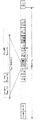
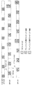
F−DPCHに類似するフォーマットを有し、異なるチャネル化コードを使用するダウンリンクの物理的なチャネルは、PCIを信号伝達するためにNodeBに使用することができ、F−DPCHのようなものと呼ばれ得る。F−DPCHのようなチャネルおよびそのフィールドについてのフレーム構造の一例が、図7および表10にそれぞれ示される。F−DPCHのようなチャネルを用いることは、ダウンリンクの同期に影響を及ぼす可能性はなく、DPDCHの構成とは独立しているものであり得る。信号伝達の位相および/または振幅は、F−DPCHのようなチャネルを用いることを含み得る。 The downlink physical channel, which has a format similar to F-DPCH and uses different channelization codes, can be used by NodeB to signal PCI, such as F-DPCH. Can be called. An example of a frame structure for a channel such as F-DPCH and its fields is shown in FIG. 7 and Table 10, respectively. Using a channel such as F-DPCH may not affect downlink synchronization and may be independent of the DPDCH configuration. The phase and / or amplitude of signaling may include using a channel such as F-DPCH.
振幅情報は、位相情報よりもゆっくり変化し得るものであり、振幅についての量子化レベルは、位相より低いものであり得る。ダウンリンク信号伝達のリソースの効率的な使用は、F−DPCHのようなチャネルを介して位相情報を信号伝達することが含まれてもよく、振幅情報は、既存のF−DPCHまたはダウンリンクDPCCHのチャネルを介して信号伝達されてもよい。DPDCHが構成されていない場合、幅情報は、いくつかのF−DPCHのスロットの送信電力制御(TPC)フィールドの全部または一部をオーバーライドすることによって信号が送信されてもよい。例えば、TPCの命令およびPCIの振幅情報は、時分割多重化を用いて送信することができ、PCIの振幅情報は、TPCの命令より低い速度で送信され得る。同様に、DPDCHが構成されている場合、振幅情報は、TPCのフィールドの全部もしくは一部、または1つまたは複数のDPCCHのスロットのパイロットフィールド(pilot field)の一部をオーバーライドすることによって信号伝達されてもよい。TPCのビットおよび振幅のビットは、1つのQPSKのシンボルに組み合されてもよく、それらの品質は、F−DPCHまたはDPCCHの送信電力を増強することによって補償され得る。図8〜図13は、本明細書に開示した方法および装置は、他の位相情報および振幅情報で使用できるが、2ビットの位相情報および1ビットの振幅情報を含む例を示す。 The amplitude information can change more slowly than the phase information, and the quantization level for the amplitude can be lower than the phase. Efficient use of downlink signaling resources may include signaling phase information via a channel such as F-DPCH, where the amplitude information is either an existing F-DPCH or downlink DPCCH. May be signaled through other channels. If DPDCH is not configured, the width information may be signaled by overriding all or part of the transmit power control (TPC) field of some F-DPCH slots. For example, TPC commands and PCI amplitude information may be transmitted using time division multiplexing, and PCI amplitude information may be transmitted at a lower rate than TPC commands. Similarly, when the DPDCH is configured, the amplitude information is signaled by overriding all or part of the TPC field, or part of the pilot field of one or more DPCCH slots. May be. TPC bits and amplitude bits may be combined into one QPSK symbol, and their quality may be compensated by increasing the transmit power of F-DPCH or DPCCH. FIGS. 8-13 illustrate examples in which the methods and apparatus disclosed herein can be used with other phase information and amplitude information, but include 2-bit phase information and 1-bit amplitude information.
図8は、F−DPCHを用いてプリコーディングの重みの振幅情報を信号伝達する方法の一例を示しており、振幅情報は、TPCのフィールドをオーバーライドすることができる。図9は、F−DPCHを用いてプリコーディングの重みの振幅情報を信号伝達する方法の一例を示しており、振幅情報は、TPCのフィールドの半分をオーバーライドすることができる。図10は、F−DPCHを用いてプリコーディングの重みの振幅情報を信号伝達する方法の一例を本明細書に示しており、振幅情報は、オーバーライドされたTPCのフィールド上の電力増強で、TPCのフィールドの半分をオーバーライドすることができる。図11は、DPDCHを用いてプリコーディングの重みの振幅情報を信号伝達する方法の一例を示しており、振幅情報は、TPCのフィールドをオーバーライドすることができる。図12は、DPDCHを用いてプリコーディングの重みの振幅情報を信号伝達する方法の一例を示しており、振幅情報は、オーバーライドされたTPCまたはパイロットフィールド上の電力増強で、部分的なTPCのフィールドまたはパイロットフィールドをオーバーライドすることができる。図13Aは、F−DPCHのようなチャネルを用いてプリコーディングの重みの振幅情報を信号伝達する方法の一例を示しており、振幅情報は、定期的に位相の成分をオーバーライドすることができる。図13Aに示す方法は、図2に示す方法に類似する。より遅い速度が、振幅成分に適用されてもよく、位相の成分を送信するのに使用されるチャネル上で送信され得る。図13Bは、F−DPCHのようなチャネルを用いてプリコーディングの重みの位相情報を信号伝達する方法の一例を示す。 FIG. 8 shows an example of a method of signaling amplitude information of precoding weights using F-DPCH, and the amplitude information can override a TPC field. FIG. 9 shows an example of a method of signaling amplitude information of precoding weights using F-DPCH, and the amplitude information can override half of the TPC field. FIG. 10 shows one example of a method for signaling precoding weight amplitude information using F-DPCH, where the amplitude information is a power boost on the overridden TPC field, and TPC You can override half of the fields. FIG. 11 shows an example of a method for signaling amplitude information of precoding weights using DPDCH, and the amplitude information can override a TPC field. FIG. 12 shows an example of a method for signaling amplitude information of precoding weights using DPDCH, where the amplitude information is a power enhancement on an overridden TPC or pilot field, and a partial TPC field. Or the pilot field can be overridden. FIG. 13A shows an example of a method for signaling precoding weight amplitude information using a channel such as F-DPCH, which can periodically override the phase component. The method shown in FIG. 13A is similar to the method shown in FIG. A slower rate may be applied to the amplitude component and may be transmitted on the channel used to transmit the phase component. FIG. 13B shows an example of a method of signaling precoding weight phase information using a channel such as F-DPCH.
位相についてのUPCIのマッピングの表は、位相の成分に使用することができる。振幅成分は、信号エラーの場合に、大きい振幅の変化に対する保護も与えるマッピングの表を使用することができる。表11は、QPSK信号などのF−DPCHのような構造を用いて1ビットの振幅の選択についての信号伝達を含む、マッピングの一例を示す。すなわち、信号の情報ビットは、QPSK変調方式についての適切な信号伝達ビットシーケンスにマッピングされてもよく、得られたQPSKにより変調した信号は、ニ相偏移キーング(BPSK)にあるように2つの層の値のうちの1つを呈する。 A UPCI mapping table for phase can be used for phase components. The amplitude component can use a mapping table that also provides protection against large amplitude changes in the case of signal errors. Table 11 shows an example of mapping including signaling for selection of 1-bit amplitude using a structure like F-DPCH such as a QPSK signal. That is, the information bits of the signal may be mapped to an appropriate signaling bit sequence for the QPSK modulation scheme, and the resulting QPSK modulated signal is in two phase shift keying (BPSK) Takes one of the values of the layer.
A1およびA2は、両アンテナについてWTRUで適用され得る振幅の設定を示し得る。例えば、A1の設定は、1番目のアンテナと2番目のアンテナの間に分けられた75%〜25%のパワーに対応し得、A2の設定は、25%〜75%のパワーの分割に対応し得る。 A1 and A2 may indicate amplitude settings that may be applied at the WTRU for both antennas. For example, the A1 setting may correspond to 75% to 25% power divided between the first antenna and the second antenna, and the A2 setting corresponds to 25% to 75% power division. Can do.
2ビットの振幅の選択は、同様のエラー保護を用いることも含み得る。振幅の大きい変化は、エンコーディングにおいてより数多くの異なるビットで保護できる。表12は、振幅の最大の差が、それぞれ振幅A1とA4の間および振幅A2とA3の間であるエンコーディングの一例を示す。 The selection of the 2-bit amplitude may also involve using similar error protection. Large changes in amplitude can be protected with a larger number of different bits in the encoding. Table 12 shows an example of an encoding where the maximum difference in amplitude is between amplitudes A1 and A4 and between amplitudes A2 and A3, respectively.
例えば、A1およびA4は、2つのアンテナの間でそれぞれ80%〜20%、および20%〜80%のパワーの分割に対応し得る。A2およびA3は、2つのアンテナの間でそれぞれ60%〜40%、および40%〜60%のパワーの分割に対応し得る。同様に、A1およびA4は、2つのアンテナの間でそれぞれ100%〜0%および0%〜100%のパワーの分割に対応し得るものであり、A2およびA3は、2つのアンテナの間でそれぞれ75%〜25%、および25%〜75%のパワーの分割に対応し得る。 For example, A1 and A4 may correspond to a power split of 80% -20% and 20% -80% between the two antennas, respectively. A2 and A3 may correspond to a power split between the two antennas of 60% to 40% and 40% to 60%, respectively. Similarly, A1 and A4 may correspond to a power split of 100% to 0% and 0% to 100% between the two antennas, respectively, and A2 and A3 are respectively between the two antennas. It may correspond to a power split of 75% to 25%, and 25% to 75%.
重みの情報は、WTRUからDPCCHを介して信号伝達され得る。これは、DPCCH上で重みの情報を明示的に信号伝達することを含み得る。UE/WTRUは、DPCCHのチャネル上でアップリンクについて実際のプリコーディングの重みの情報を信号伝達することができる。DPCCHのスロットフォーマットは、AWIを保持するために使用できる。表13は、2つのAWIのビットの送信を支援するために2つのスロットフォーマット(5および6)を含むDPCCHのフィールドの一例を示す。 Weight information may be signaled from the WTRU via the DPCCH. This may include explicitly signaling weight information on the DPCCH. The UE / WTRU may signal the actual precoding weight information for the uplink on the DPCCH channel. The DPCCH slot format can be used to hold the AWI. Table 13 shows an example of a DPCCH field that includes two slot formats (5 and 6) to support transmission of two AWI bits.
別のスロットフォーマットは、AWIを保持するためのフィールドを再利用することによって使用することができる。例えば、表13を参照すると、スロットフォーマット0を使用することができ、TFCIのフィールドは、重みの情報を信号伝達するように再利用することができる。このフィールドの使用は、WTRUの構成に基づいて暗黙的であり得る。例えば、WTRUは、アップリンクDCHなしであると共に、アップリンクの閉ループの送信ダイバーシチを用いて構成することができ、WTRUは、DPCCHのスロットフォーマット0で構成することができ、TFCIのフィールドのビットは、AWIを保持するように暗黙的に使用することができる。
Another slot format can be used by reusing the field to hold the AWI. For example, referring to Table 13,
TPCのフィールドは、AWIを保持するために使用することができる。AWIは、TPCを定期的に置き換えることができる。この期間は、ネットワークによって設定することができない。 The TPC field can be used to hold the AWI. AWI can replace TPC periodically. This period cannot be set by the network.
DPCCHのスロットフォーマットは、他のフィールドに加えてAWIの送信を可能にするように定期的に変更することができる。例えば、WTRUは、全てのNformat−changeのスロットで、WTRUがAWIを保持する交互の(異なる)スロットフォーマットを用いて送信するように、ネットワークによって構成することができる。表13を参照すると、WTRUは、スロットフォーマット0を用いて送信するように構成されてもよく、全てのNformat−changeのスロットで交互のフォーマットとしてフォーマット6を使用してもよい。スロットフォーマットの様々な組み合わせを使用することができる。WTRUは、交互のスロットフォーマットを用いて送信するときに、DPCCHで一時的なパワーオフセット(power offset)を適用することができる。このオフセットは、縮小したサイズのフィールドで信頼性の潜在的な減少を補償することができる。例えば、スロットフォーマット6は、スロットフォーマット0の代替として使用することができ、パイロットフィールドの長さは、33%だけ縮小することができる。DPCCHの電力、パイロットフィールドは、チャネルの評価への影響を抑えるために増大させられてもよい。
The slot format of the DPCCH can be changed periodically to allow AWI transmission in addition to other fields. For example, the WTRU may be configured by the network so that in all N format-change slots, the WTRU transmits using an alternate (different) slot format that holds the AWI. Referring to Table 13, the WTRU may be configured to transmit using
スロットフォーマット5は、スロットフォーマット4の代替として使用することができ、TPCのフィールドの長さは、50%だけ縮小することができる。DPCCHの電力は、TPCのエラー率に対する影響を下げるように増大させられてもよい。
現在の重みの情報が、NodeBによってWTRUに信号伝達される場合、WTRUが、PCIの新しい重みが受信され適用されたことをNodeBに伝えることができるように、WTRUは、DPCCHで新しい重みのインジケータビット(または複数のビット)を切り替えることによって、暗黙的に重みを信号伝達することができる。NodeBは、送られたPCIの重みが、受信され適用されたと仮定することができる。1つまたは複数のビットが切り換えられない場合、NodeBは、先の重みが適用され、NodeBによって送られたデータの信号の送信が、適切に受信されなかったと仮定することができる。場合によっては、新しい重みのインジケータの1つまたは複数のビットが切り換わらず、NodeBが新しいPCIを送らないとき、NodeBは、PCIまたは現在のPCIを再送することができる。プリコーディングされたDPCCHについては、NodeBは、古いPCIおよび新しいPCIを用いてブラインド検出し、新しい重みのインジケータの1つまたは複数のビットを検査してバージョンが有効であるか判定することができる。 If the current weight information is signaled to the WTRU by the NodeB, the WTRU may indicate the new weight indicator on the DPCCH so that the WTRU can inform the NodeB that the new PCI weight has been received and applied. Weights can be implicitly signaled by switching bits (or bits). The NodeB may assume that the sent PCI weights have been received and applied. If one or more bits are not switched, the NodeB can assume that the previous weights were applied and that the transmission of the data signal sent by the NodeB was not properly received. In some cases, when one or more bits of the new weight indicator do not switch and the NodeB does not send a new PCI, the NodeB can retransmit the PCI or current PCI. For the precoded DPCCH, the NodeB can blind detect with the old and new PCIs and examine one or more bits of the new weight indicator to determine if the version is valid.
重みの情報は、E−DPCCHを介してWTRUから信号伝達されてもよい。E−DPCCHが、E−DPDCHに関連し、E−DPDCHを用いて送られ得るとき、データ復調に使用され得る重みの情報の信号伝達は、以下の1つまたは任意の組み合わせを使用することができる。筋書きの1つは、例えば、適用されたプリコーディングの重みが、限られた数で設定されたプリコーディングの重みから選択されると仮定すると、E−DPCCHが、WTRUでE−DPDCHと同じプリコーディングの重みで適用されるときに、E−DPCCHをブラインドデコーディング(blind decoding)することによって重みの情報を信号伝達することを暗黙的に含み得る。例えば、4つのプリコーディングの重みの選択が存在し、そこで、NodeBは、WTRUでプリコーディングの重みが使用されるか発見するために構成されたプリコーディングの重みの選択を試みることによってE−DPCCHのブラインドデコーディングを使用する。重みの情報は、E−DPCCHで明示的に信号伝達することができる。 Weight information may be signaled from the WTRU via the E-DPCCH. When the E-DPCCH is related to the E-DPDCH and can be sent using the E-DPDCH, signaling of weight information that can be used for data demodulation may use one or any of the following: it can. One scenario is that, for example, assuming that the applied precoding weights are selected from a limited number of precoding weights set, the E-DPCCH is the same as the E-DPDCH in the WTRU. When applied with coding weights, it may implicitly include signaling weight information by blind decoding the E-DPCCH. For example, there are four precoding weight selections, where the NodeB can select E-DPCCH by attempting to select a precoding weight configured to discover if the WTRU uses precoding weights. Use blind decoding. Weight information can be explicitly signaled on the E-DPCCH.
図14は、チャネルコーディングチェーンを用いたE−DPCCHで重みの情報を信号伝達する一例を示す。信号伝達されるAWIの数、NumAWIに応じて、新しい(30,Num_total)のリードマラー(RM)符号を設計することができ、それによってNumAWIのビットの重みの情報が、NumRSNビットの再送シーケンス番号(RSN:Retransmission Sequence Number)、NumE−TFCIビットのE−DCHトランスポートフォーマット組み合わせ識別子(E−TFCI:E−DCH Transport Format Combination Identifier)、およびNumhappyビットビットのハッピービットでエンコードすることができる。ここで、Numtotal=Numhappyビット+NumRSN+NumE−TFCI+NumAWIである。例えば、NumRSN=2、NumE−TFCI=7、Numhappyビット=1または0である。DPCCHを介して重みの情報を暗黙的に信号伝達するために、重みの1つまたは複数のビットを切り換えることによって、重みの情報は、E−DPCCHを介して暗黙的に信号伝達することができる。 FIG. 14 shows an example of signaling weight information on E-DPCCH using a channel coding chain. Depending on the number of AWIs signaled, NumAWI, a new (30, Num_total) Reed-Muller (RM) code can be designed, so that the NumAWI bit weight information is the NumRSN bit retransmission sequence number ( RSN: Retransmission Sequence Number), E-DCH transport format combination identifier (E-TFCI: E-DCH Transport Format Combination Identifier) of NumE-TFCI bits, and Happy bit of Numhappy bit bits. Here, Numeral = Numhappy bit + NumRSN + NumE-TFCI + NumAWI. For example, NumRSN = 2, NumE-TFCI = 7, and Numhappy bit = 1 or 0. The weight information can be implicitly signaled via the E-DPCCH by switching one or more bits of the weight to implicitly signal the weight information via the DPCCH. .
NodeBは、チャネルがランク2の送信を支援できることをWTRUに示すことができるが、WTRUは、次の送信が単一のトリームの送信であってもよいか、または二重のストリームの送信であってもよいかの最終決定を有するように柔軟性が与えられてもよい。このように、ランク1の送信の上のランク2の送信によって使用される追加のオーバーヘッドをセーブすることができる。WTRUは、関連したE−DCH送信のランク情報をNodeBに示すことができる。
The NodeB may indicate to the WTRU that the channel can support rank-2 transmissions, but the WTRU may either send a single stream or send a dual stream. Flexibility may be given to have a final determination of what may be. In this way, additional overhead used by
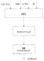
一実施形態は、一次のE−DCHまたはE−DPDCHのストリームに関連したE−DPCCHのチャネルを介して信号伝達される1ビットランク情報を含むことができる。MIMO可能なUL WTRUについては、旧来のE−TFCのサブセットが支持されてもよく、それによってE−TFCIのフィールド中の未使用のビットが、ランク情報を信号伝達するために使用できる。交互に、新しい(30,11)リードマラー符号が使用されてもよく、それによって1ビットランク情報は、2ビットのRSN、7ビットのE−TFCI、および1ビットのハッピービットでエンコードすることができる。図15に、ランク情報を含むE−DPCCHのエンコーディングチェーンを示す。 One embodiment may include 1-bit rank information signaled over an E-DPCCH channel associated with a primary E-DCH or E-DPDCH stream. For MIMO capable UL WTRUs, a subset of legacy E-TFC may be supported so that unused bits in the E-TFCI field can be used to signal rank information. Alternately, a new (30,11) Reed-Muller code may be used so that 1-bit rank information can be encoded with 2 bits of RSN, 7 bits of E-TFCI, and 1 bit of happy bits. . FIG. 15 shows an E-DPCCH encoding chain including rank information.
明示的ランク情報(RI)の情報は、アップリンクにおいて信号を送信することができる。NodeBは、ランク情報をブラインドで検出することができる。例えば、NodeBは、一次のE−DCHまたはE−DPDCHのストリーム、および二次のE−DCHまたはE−DPDCHのストリームにそれぞれ関連したE−DPCCHの受信した電力を測定することができる。2つの測定した電力の比が、閾値より高いまたは低い場合、ランク−1の送信が決定され得る。 Explicit rank information (RI) information can be signaled in the uplink. NodeB can detect rank information blindly. For example, the NodeB may measure the received power of the E-DPCCH associated with the primary E-DCH or E-DPDCH stream and the secondary E-DCH or E-DPDCH stream, respectively. If the ratio of the two measured powers is higher or lower than the threshold, rank-1 transmission may be determined.
重みの情報は、NodeBからWTRUへDLで信号伝達することができる。プリコーディングの重みの情報(例えば、UPCI)は、時分割多重化(TDM)を用いて送信電力制御(TPC)の命令で、F−DPCHで信号伝達することができる。図16は、F−DPCHのフレーム構造の一例を示しており、UPCIおよび(TPC)の命令は、一定のTDMのパターンで信号伝達される。例えば、UPCIは、全てのサブフレーム(TTI)で信号伝達され、TPCの命令は、UPCIに用いられる2つのスロットの間のスロットで信号伝達され、具体的には、i番目のスロットについては、i mod 3=0の場合、UPCIを送信し、他の場合は、TPCの命令を送信する。コードブックサイズに応じて、表14に導入されたUPCIを保持する他のフォーマットが使用されてもよい。スロットフォーマットのインデックスとUPCIについてのF−DPCHフィールドの定義間のマッピングは、表14とは異なる形態をとってもよい。
Weight information can be signaled in DL from the NodeB to the WTRU. Precoding weight information (eg, UPCI) can be signaled on the F-DPCH with a transmit power control (TPC) command using time division multiplexing (TDM). FIG. 16 shows an example of the frame structure of F-DPCH, where UPCI and (TPC) commands are signaled in a constant TDM pattern. For example, UPCI is signaled in all subframes (TTI), and TPC instructions are signaled in a slot between two slots used for UPCI, specifically for the i th slot, When i
TPCの命令は、TPCとPWIの両方からなる新しいF−DPCCHの構造を有する全てのスロットで信号伝達されなくてもよく、ULについては、UPCIを保持するスロットに対応するDPCCHのスロットは、DPCCHの送信電力を調整できなくてもよいが、TPCの命令を保持するF−DPCHのスロットに対応する先のスロットと同じ電力レベルを維持する。 TPC commands may not be signaled in all slots with a new F-DPCCH structure consisting of both TPC and PWI, and for UL, the DPCCH slot corresponding to the slot holding UPCI is DPCCH However, the same power level as the previous slot corresponding to the slot of the F-DPCH that holds the TPC command is maintained.
DL出力制御の動作を修正することができる。全てのスロットでTPCの命令を保持するF−DPCHのフレーム構造での旧来の目標のSIRは、開ループ出力制御(OLPC)によってTPCブロックエラー率(BER)に基づいて更新することができ、TPCとPWIの両方からなる新しいF−DPCCH構造での目標の信号対干渉比(SIR)は、TPC BERに基づいて、またはDLPCについてのTPCとPWIの両方のエラー率に基づいて評価することができる。 The operation of DL output control can be modified. The legacy target SIR in the F-DPCH frame structure, which holds the TPC command in all slots, can be updated based on the TPC block error rate (BER) by open loop power control (OLPC). The target signal-to-interference ratio (SIR) in the new F-DPCCH structure consisting of both TPC and PWI can be evaluated based on TPC BER or based on both TPC and PWI error rates for DLPC .
UPCIは、TPCの命令でTDMを用いて送信することができ、TDMは、スロット内で実行される。これは、例えば、TPCの命令について、送信されることになり得るUPCIのフィールドごとに、異なるF−DPCHのスロットフォーマットを用いて実現することができる。また、同じチャネル化コードを使用してTPCおよびUPCIを保持することができ、それによってWTRUにおける実施をさらに簡単にする。 UPCI can be transmitted using TDM at the command of TPC, and TDM is performed in a slot. This can be achieved, for example, using different F-DPCH slot formats for each UPCI field that may be transmitted for TPC commands. Also, the same channelization code can be used to hold TPC and UPCI, thereby further simplifying implementation in the WTRU.
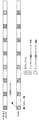
表14を参照すると、WTRUは、TPCの命令を受信するためにF−DPCHのスロットフォーマット0、およびUPCIを受信するためにF−DPCHのスロットフォーマット1Aを用いて構成されてもよい。したがって、WTRUは、図17に示すように、同じスロット内でTDMにおけるTPCおよびUPCIの情報を受信する。
Referring to Table 14, the WTRU may be configured with F-
WTRUは、TPCの命令を受信するためにF−DPCHのスロットフォーマット0を用いて構成されてもよく、UPCIを受信するためにF−DPCHのスロットフォーマット1Aおよび2Aを用いて構成されてもよい。したがって、図18に示すように、WTRUは、同じスロット内でTDMにおけるTPCおよびUPCIの情報を受信する。しかし、図17に示す例とは異なり、2つ以上のフィールドを使用してUPCIを保持する。WTRUは、両フィールドから個々の部分的なUPCIを組み合わせて、最終的なUPCIのインデックスを形成することができる。
The WTRU may be configured with F-
同じスロット内で2つ以上の2ビットのUPCIが送信されるとき、F−DPCHのフォーマットの新しいセットは、適切なフィールドの長さのために特定することができる。例えば、4ビットのUPCIが使用されるとき、新しいフォーマットは、以下の表15に示されるように定義することができる。 When two or more 2-bit UPCIs are transmitted in the same slot, a new set of F-DPCH formats can be specified for the appropriate field length. For example, when 4-bit UPCI is used, a new format can be defined as shown in Table 15 below.
表15では、スロットフォーマット8Aは、(その論理的な一部を除いて)UPCIのフィールドが、次のスロットに重なるという点で特別である。図19は、UPCIが隣接したスロットに重なるF−DPCHのスロットフォーマットを示す。 In Table 15, the slot format 8A is special in that the UPCI field (except for its logical part) overlaps the next slot. FIG. 19 shows a slot format of F-DPCH in which UPCI overlaps adjacent slots.
適宜、UPCIは、全てのスロットで送信することができず、この場合、WTRUは、知られたDTXの期間中にUPCIに関連しているフィールドを監視できない。 As appropriate, UPCI cannot be transmitted in all slots, in which case the WTRU cannot monitor the fields associated with UPCI during a known DTX.
コードワードの情報を信号伝達されるビットシーケンスにマッピングするために使用できるいくつかの方法がある。以下の方法は、意の順序または組み合わせで使用することができる。 There are several methods that can be used to map the codeword information into the signaled bit sequence. The following methods can be used in any order or combination.
第1の方法では、実際のコードワードの情報は、UPCI上に保持される特定のビットシーケンスにマッピングすることができる。第2の方法では、コードブックにおけるコードワードは、信号エラーの場合の大きい位相の変化を保護するように、特定のビットシーケンスにマッピングされる。例えば、グレイ符号化を用いたF−DPCHの場合、ビットの組み合わせ11,00に対応するコードワードは、ビットの組み合わせ10,01に対応するコードワードと全く同じより大きいプリコーダの位相差を有する。したがって、第1の群におけるコードワードと第2の群におけるコードワードの間の位相差は、各群内より小さい距離を有し得る。したがって、一実施形態では、180度異なるプリコーダの位相は、ペアであり、反対(論理的に逆)であるビットシーケンスを有する割り当てられたコードワードである。シーケンスのペアを特徴付ける等価なやり方は、最大のハミング距離を有するビットシーケンスのペアが、180度異なるプリコーダ位相値を表すように使用されることである。表16は、180度の差異を有するプリコーダ位相値についての反対のビットシーケンスを有するそのような一例のマッピングを示す。この例の位相コードブックのマッピングは、プリコーダの重みの間で可能な位相の一例を示す。すなわち、コードワードの位相は、2つのアンテナシステムにおいて信号に加えられる2つのプリコーダの重みの間の所望の位相差を表す。意図した0度のコードワードの位相は、同じ位相値を有する重みを意味し、一方、180度のコードワードの位相は、180度異なる位相を有するプリコーディングの重みを意味する。
In the first method, the actual codeword information can be mapped to a specific bit sequence held on the UPCI. In the second method, codewords in the codebook are mapped to specific bit sequences to protect against large phase changes in case of signal errors. For example, in the case of F-DPCH using Gray coding, the codeword corresponding to the
信号伝達ビットは、任意の適切なコンステレーションを用いて変調することができる。 The signaling bits can be modulated using any suitable constellation.
図20Aは、方法2000の一実施形態の構成図である。ブロック2002では、無線送受信ユニット(WTRU)は、所望のプリコーダ位相値に対応する信号伝達ビットのシーケンスを表すプリコーディングインジケータ信号を受信する。ブロック2004では、WTRUは、信号伝達ビットのシーケンスを複数の所定の信号伝達ビットのシーケンスと比較することによって所望のプリコーダ位相値を得る。上述のように、所定の信号伝達ビットのシーケンスのペアは、互いに反対であり、最大の増分だけ異なるプリコーダ位相値に対応するようにマッピングされ、これはしばしば180度に設定される。ブロック2006では、WTRUは、複数のアンテナを介して送信されるWTRUのアップリンク信号のストリームに重み値のセットを適用し、重み値のセットは、所望のプリコーダ位相値に等しい位相差を有する。プリコーディングインジケータ信号は、広帯域符号分割多重アクセス方式のダウンリンク信号送信の部分チャネルで運ぶことができる。信号伝達ビットのシーケンスは、長さが2つの情報ビットに相当し、これは、BPSK変調が使用される場合、2つのデータビットとして表わすことができ、またはQPSK変調が使用される場合、4つのデータビットとして表わすことができる。プリコーディングインジケータ信号は、信号伝達ビットのシーケンスの変調されたバージョンである。
FIG. 20A is a block diagram of an embodiment of a
一対の所定の信号伝達ビットのシーケンスおよび対応するプリコーダ位相値は、以下のマッピング、すなわち、
シーケンス00:位相0度、
シーケンス11:位相180度、
シーケンス01:位相90度、
シーケンス10:位相270度
に従う。
The sequence of a pair of predetermined signaling bits and the corresponding precoder phase value are mapped as follows:
Sequence 00:
Sequence 11: phase 180 degrees,
Sequence 01: 90 degree phase,
Sequence 10: Follows phase 270 degrees.
図20Bに示される方法2010は、ブロック2012において、無線送受信ユニット(WTRU)で、第1のプリコーダ位相値に対応する信号伝達ビットの第1のセットを表す第1のプリコーディングインジケータ信号を受信することを示す。ブロック2014では、重み値の第1のセットを、複数のアンテナを介して送信されるWTRUのアップリンク信号のストリームに適用する。重み値の第1のセットは、第1のプリコーダ位相値に等しい位相差を有する。ブロック2016では、第1のプリコーダ位相値とは180度異なると共に、信号伝達ビットの第1のセットの反対である信号伝達ビットの第2のセットに対応する第2のプリコーダ位相値に対応する信号伝達ビットの第2のセットを表す第2のプリコーディングインジケータ信号を受信する。ブロック2018では、WTRUは、WTRUのアップリンク信号のストリームに重み値の第2のセットを適用する。重み値の第2のセットは、第2のプリコーダ位相値に等しい位相差を有する。
The
プリコーディングインジケータ信号は、広帯域符号分割多重アクセス方式のダウンリンク信号送信の部分チャネルで運ぶことができ、一実施形態では、信号ビットの第1のセットおよび信号伝達ビットの第2のセット、ならびにそれぞれの対応する第1のプリコーダ位相値および第2のプリコーダ位相値は、
シーケンス00、位相0度、およびシーケンス11、位相180度;またはシーケンス01、位相90度、およびシーケンス10、位相270度のいずれかである。
The precoding indicator signal may be carried on a partial channel of wideband code division multiple access downlink signal transmission, and in one embodiment, a first set of signaling bits and a second set of signaling bits, and respectively The corresponding first precoder phase value and second precoder phase value of
無線送受信装置の一実施形態では、WTRUは、プリコーディングインジケータ信号を受信し、対応する信号伝達ビットのシーケンスを復元するように構成される受信機と、信号伝達ビットのシーケンスを複数の所定の信号伝達ビットのシーケンスと比較することによって、所望のプリコーダ位相値を信号伝達ビットのシーケンスから得るように構成されるコントロールチャネルのプロセッサ(control channel processor)であって、所定の信号伝達ビットのシーケンスのペアは、互いに反対であり、180度異なるプリコーダ位相値に対応するコントロールチャネルのプロセッサと、重み値のセットをアップリンク信号のストリームに加えて、複数のアンテナを介して送信するように構成される送信機であって、重み値のセットは、所望のプリコーダ位相値に等しい位相差を有する送信機とを備える。 In one embodiment of a wireless transceiver, the WTRU receives a precoding indicator signal and reconstructs a corresponding sequence of signaling bits and a sequence of signaling bits to a plurality of predetermined signals. A control channel processor configured to obtain a desired precoder phase value from a sequence of signaling bits by comparing with a sequence of signaling bits, comprising a predetermined pair of signaling bits Are opposite to each other and are configured to add a set of weight values to a stream of uplink signals in addition to a processor of a control channel corresponding to precoder phase values that differ by 180 degrees and transmit via multiple antennas Machine, The set of weight values comprises a transmitter having a phase difference equal to the desired precoder phase value.
この装置は、メモリデバイスをさらに備えてもよく、一対の所定の信号伝達ビットのシーケンスおよび対応するプリコーダ位相値は、以下のマッピング、すなわち、
シーケンス00:位相0度、
シーケンス11:位相180度、
シーケンス01:位相90度、
シーケンス10:位相270度
に従って記憶される。
The apparatus may further comprise a memory device, wherein the pair of predetermined signaling bit sequences and the corresponding precoder phase values are mapped as follows:
Sequence 00:
Sequence 11: phase 180 degrees,
Sequence 01: 90 degree phase,
Sequence 10: Stored according to phase 270 degrees.
コントロールチャネルのプロセッサは、広帯域符号分割多重アクセス方式のダウンリンク信号送信の部分チャネルからプリコーディングインジケータ信号を復元するようにさらに構成されてもよい。 The processor of the control channel may be further configured to recover the precoding indicator signal from a partial channel of downlink signal transmission of the wideband code division multiple access scheme.
別の実施形態では、無線基地局装置は、無線送信受信ユニットのプリコーディングの重みの間の位相オフセットを表す所望のプリコーダの位相を決定するように構成されるプロセッサと、所望のプリコーダの位相を信号伝達ビットのシーケンスに変換するように構成されるコントロールチャネルのプロセッサであって、信号伝達ビットのシーケンスは、所定の信号伝達ビットのシーケンスのペアが、互いに反対であり、180度異なるプリコーダ位相値に対応する複数の所定の信号伝達ビットのシーケンスから選択されるコントロールチャネルのプロセッサと、信号伝達ビットのシーケンスに応じてプリコーディングインジケータ信号を生成するように構成される送信機とを備える。 In another embodiment, a radio base station apparatus comprises: a processor configured to determine a desired precoder phase representing a phase offset between precoding weights of a radio transmission and reception unit; and a desired precoder phase. A processor of a control channel configured to convert to a sequence of signaling bits, wherein the sequence of signaling bits is a precoder phase value that is 180 degrees different from each other with a predetermined sequence of signaling bits being opposite to each other A processor of a control channel selected from a plurality of predetermined signaling bit sequences corresponding to, and a transmitter configured to generate a precoding indicator signal in response to the signaling bit sequence.
基地局は、メモリデバイスをさらに備えてもよく、一対の所定の信号伝達ビットのシーケンスおよび対応するプリコーダ位相値は、以下のマッピング、すなわち、
シーケンス00:位相0度、
シーケンス11:位相180度、
シーケンス01:位相90度、
シーケンス10:位相270度
に従って記憶される。
The base station may further comprise a memory device, and the sequence of a pair of predetermined signaling bits and the corresponding precoder phase value are mapped as follows:
Sequence 00:
Sequence 11: phase 180 degrees,
Sequence 01: 90 degree phase,
Sequence 10: Stored according to phase 270 degrees.
コントロールチャネルのプロセッサは、広帯域の符号分割多重アクセス方式のダウンリンクの信号の部分チャネルを介して信号伝達ビットのシーケンスを送るようにさらに構成されてもよい。 The control channel processor may be further configured to send a sequence of signaling bits over a partial channel of the wideband code division multiple access downlink signal.
E−RGCHまたはE−HICHの物理的なチャネルの構造は、アップリンク送信ダイバーシチTXD/MIMOについてのダウンリンクの信号の情報を保持するように再利用することができる。 The physical channel structure of E-RGCH or E-HICH can be reused to retain downlink signal information for uplink transmit diversity TXD / MIMO.
F−PCICHは、PCIの情報を運ぶF−DPCHのようなチャネルである。以下では、便宜のために、1つのPCIのシンボルは、プリコーディングのコードブック(pre−coding codebook)内の特定のコードワードを示す2つのPCIの情報ビットである。また、1つのF−PCICHのリソースは、1つのQPSKのシンボルに対応しすなわち、全てのF−PCICHのスロットは、10個のF−PCICHのリソースを含む。 F-PCICH is a channel like F-DPCH that carries PCI information. In the following, for convenience, one PCI symbol is two PCI information bits indicating a specific codeword in a pre-coding codebook. Also, one F-PCICH resource corresponds to one QPSK symbol, that is, all F-PCICH slots include 10 F-PCICH resources.
3つのスロットのPCIの更新速度(2ms)(信号伝達間隔)、およびPCIのコードブックの4のサイズ(2ビット、または1つのQPSKのシンボル)については、以下の方法を使用してPCIの情報を送信することができる。 For the PCI update rate (2 ms) for 3 slots (signaling interval), and the PCI codebook size of 4 (2 bits, or 1 QPSK symbol), the PCI information using the following method: Can be sent.
第1の方法では、信号伝達間隔ごとに1つのPCIのシンボルが送信され、すなわち、1つのF−PCICHのリソースが送信され、そして他のスロットでF−PCICHのリソースがDTXされる。例えば、3スロットの信号伝達の場合では、3スロットごとに、PCIのシンボルが1つのスロットだけで送信され、他の2つのスロット上の対応するF−PCICHのリソースは、(そのWTRUについて)DTXされる。図21は、信号伝達間隔ごとに1つのPCIのシンボルを送信し、DTXがサブフレーム(3つのスロット)に入る方法を示す。この方法は、方法が最小の時間および符号空間リソース(code−space resource)を使用するので有利であり得る。DTXの期間は、NodeBによってPCIインジケータを他のWTRUに信号で送信するために使用できる。 In the first method, one PCI symbol is transmitted every signaling interval, that is, one F-PCICH resource is transmitted, and the F-PCICH resource is DTX in another slot. For example, in the case of 3 slot signaling, every 3 slots, a PCI symbol is transmitted in only one slot, and the corresponding F-PCICH resources on the other 2 slots are DTX (for that WTRU). Is done. FIG. 21 shows a method in which one PCI symbol is transmitted every signaling interval, and DTX enters a subframe (three slots). This method may be advantageous because the method uses minimal time and code-space resources. The DTX period can be used by the NodeB to signal the PCI indicator to other WTRUs.
第2の方法では、F−PCICHのリソースごとに1つのPCIのシンボルが送信され、信号伝達間隔(ここではN=3)にわたってPCIのシンボル繰り返しを伴う。図22Aは、3つの隣接したF−PCICHのスロットにわたるF−PCICHのリソースが、1つのPCIのシンボルを送信するために使用される、PCIのシンボルを送信する方法を示す。第2の方法は、同じレベルの信頼性を実現するために、第1の方法よりも少ないピーク電力を必要とし得る。 In the second method, one PCI symbol is transmitted for each F-PCICH resource, with PCI symbol repetition over a signaling interval (N = 3 in this case). FIG. 22A illustrates a method of transmitting a PCI symbol, where F-PCIICH resources across three adjacent F-PCICH slots are used to transmit one PCI symbol. The second method may require less peak power than the first method to achieve the same level of reliability.
第3の方法では、F−PCICHのリソースごとに1つのPCIのシンボルが送信され、同じF−PCICHのスロット内で今度はN個(本明細書では、N=3)の隣接したF−PCICHのリソースにわたるPCIの繰り返しを伴う。図22Bは、F−PCICHのリソースごとに1つのPCIのシンボルが、送信され、PCI繰り返しを伴う、PCIを送信する方法を示す。この方法は、全ての信号エネルギーがたった1つのスロットの間隔に集中されるので、より少ない待ち時間を必要とし得る。 In the third method, one PCI symbol is transmitted for each F-PCICH resource, and this time N (here, N = 3) adjacent F-PCICHs in the same F-PCICH slot. With repeated PCI over multiple resources. FIG. 22B shows a method for transmitting PCI, with one PCI symbol transmitted for each F-PCICH resource, with PCI repetition. This method may require less latency because all signal energy is concentrated in only one slot interval.
適宜、図22Aおよび図22Bの単純なり返し方式についてのダウンリンクのPCI送信の信頼性は、コンステレーション再マッピングを送信されるシンボルに加えることによって改善され得る。これは、3つのF−PCICHのリソースにわたって同じPCIのコードワードを送信するごとに、異なるQPSKのコンステレーションを加えることによって実現することができる。したがって、コンステレーションマッピングは、3つの送信後、最小のユークリッド距離が4aであるように設計されてもよい。 If appropriate, the reliability of the downlink PCI transmission for the simple return scheme of FIGS. 22A and 22B may be improved by adding a constellation remapping to the transmitted symbols. This can be achieved by adding a different QPSK constellation for every transmission of the same PCI codeword across three F-PCICH resources. Thus, the constellation mapping may be designed such that after three transmissions, the minimum Euclidean distance is 4a.
コンステレーション再マッピングを説明するために、4つのPCIのコードワードは、P0、P1、P2およびP3と名付けられる。表17に、これらのコードワードについてのビットシーケンスおよびQPSKのシンボルのマッピングの一例が示される。図23は、QPSKのコンステレーション再マッピングを用いた1つの可能なコンステレーションマッピングのPCI送信を示す。図23中のパラメータbは、コンステレーションのバージョンのインデックス(constellation version index)を表し、コードワードP0、P1、P2およびP3のQPSKのシンボルへのマッピングの潜在的な1セットのルールが、a=1について、表18に示される。表19に示すコンステレーションマッピングは、最小のユークリッド距離が4aであるというコンステレーションマッピングのルールを満たす。 To describe constellation remapping, the four PCI codewords are named P0, P1, P2, and P3. Table 17 shows an example of bit sequence and QPSK symbol mapping for these codewords. FIG. 23 illustrates PCI transmission of one possible constellation mapping using QPSK constellation remapping. The parameter b in FIG. 23 represents the constellation version index, and a potential set of rules for mapping codewords P0, P1, P2 and P3 to QPSK symbols is a = 1 is shown in Table 18. The constellation mapping shown in Table 19 satisfies the constellation mapping rule that the minimum Euclidean distance is 4a.
図24は、コンステレーション再マッピングの無いある可能なコンステレーションマッピングのPCI送信を示す。図25は、再マッピングない場合および再マッピングがある場合のPCIエラー率(またはシンボルエラー率)の観点での性能比較を示す。約1dBのゲインが、PCIエラー率10−2の関心の点で実現される。このゲインは、3つの送信の後のファクタによるものであり、最小のユークリッド距離は、 FIG. 24 shows a PCI transmission of one possible constellation mapping without constellation remapping. FIG. 25 shows a performance comparison in terms of PCI error rate (or symbol error rate) with no remapping and with remapping. A gain of about 1 dB is achieved at the point of interest of PCI error rate 10-2. This gain is due to a factor after three transmissions, and the minimum Euclidean distance is
から増加し、ただし、4aまでの単純な繰り返し、コンステレーション再マッピングを伴う。 But with a simple iteration up to 4a, with constellation remapping.
したがって、図21および図22に示す方法に基づいた繰り返しに対応するPCI送信の2つの改善された方法が、それぞれ図26および図27に示される。 Accordingly, two improved methods of PCI transmission corresponding to repetition based on the methods shown in FIGS. 21 and 22 are shown in FIGS. 26 and 27, respectively.
図26は、コンステレーション再マッピングを伴う3つの異なるスロットにわたるPCI送信を示す。図26に示す第1の方法では、PCIのシンボル繰り返しが信号伝達間隔(本例ではN=3)にわたっている状態で、F−PCICHのリソースごとに1つのPCIのシンボルが送信される。コンステレーションのインデックスは、周期的な繰り返しを伴う送信ごとに変化する。この方法によれば、信号のパワーは、3つのスロットにわたって広がり、提案したコンステレーション再マッピングによる同じ信号の受信品質のために最小にもされている。 FIG. 26 shows PCI transmission over three different slots with constellation remapping. In the first method illustrated in FIG. 26, one PCI symbol is transmitted for each F-PCICH resource in a state where PCI symbol repetition is over a signal transmission interval (N = 3 in this example). The constellation index changes for each transmission with periodic repetition. According to this method, the signal power is spread over three slots and is minimized due to the reception quality of the same signal with the proposed constellation remapping.
図27は、コンステレーション再マッピングを伴う1つのスロット内のPCI送信を示す。図27に示す第2の方法では、F−PCICHのリソースごとに1つのPCIのシンボルが送信され、PCIの繰り返しは、同じF−PCICHのスロット内のN個の(例えば、N=3)隣接したF−PCICHのリソースにわたり、ここでコンステレーションのインデックスは、全てのシンボルで周期的な繰り返しを伴って変化する。図27に示すように、1つのPCIのシンボルは、ここでは、3つのF−PCICHのリソースをとる。この手法の利点の1つは、PCIの送信に関連している待ち時間が、その送信のために1つのスロットしか必要とされないので、減少することである。さらに、提案したコンステレーション再マッピング手法を適用することによって、より少ない量の電力が、同じ信頼性を実現するために必要とされる。 FIG. 27 shows PCI transmission in one slot with constellation remapping. In the second method shown in FIG. 27, one PCI symbol is transmitted for each F-PCICH resource, and the PCI repetition is performed by N (for example, N = 3) neighbors in the same F-PCIICH slot. Over the F-PCICH resources, where the constellation index changes with periodic repetitions in every symbol. As shown in FIG. 27, one PCI symbol takes three F-PCICH resources here. One advantage of this approach is that the latency associated with the transmission of PCI is reduced because only one slot is required for the transmission. Furthermore, by applying the proposed constellation remapping technique, a smaller amount of power is required to achieve the same reliability.
単純な繰り返しを伴う上記の方法、またはコンステレーション再マッピングを用いる方法を用いる柔軟性をNodeBに与えるために、新しいRRCメッセージは、WTRUが、F−PCICHでのPCI送信のためにコンステレーション再マッピングを用いることを可能/不可能にするために使用することができる。 In order to give the NodeB the flexibility to use the above method with simple repetition or using constellation remapping, a new RRC message is sent by the WTRU for constellation remapping for PCI transmission in F-PCIICH. Can be used to enable / disable the use of.
WTRUは、コンステレーション再マッピングが適用されるときに、PCIを受信およびデコードするための方法を使用することができる。 The WTRU may use a method for receiving and decoding PCI when constellation remapping is applied.
WTRUは、定められたタイミングに従って第1のコンステレーションのバージョンb=0を有する新しいPCIの情報を受信し始めてもよい。WTRUは、3つ全ての異なるコンステレーションのバージョンを有するPCIの情報が、WTRUで受信されるまで、PCIの情報をデコードしない。WTRUは、3つの異なるコンステレーションのバージョンを有する受信したPCIの情報に基づいて結合検出を行うことになる。送信したPCIを検出した後、WTRUは、検出したPCIによって示されるプリコーディングの重みを適用することができる。 The WTRU may begin to receive new PCI information having the first constellation version b = 0 according to a defined timing. The WTRU does not decode PCI information until PCI information having all three different constellation versions is received at the WTRU. The WTRU will perform joint detection based on the received PCI information having three different constellation versions. After detecting the transmitted PCI, the WTRU may apply the precoding weight indicated by the detected PCI.
異なる目的に役立つが、E−RGCHおよびE−HICHは、スロット内の40ビットにエンコードされる直交シグネチャシーケンスのセットに基づいて同じチャネル構造を共有してもよく、ここで、シンボルαは、E−RACHにそれぞれ「UP」、「DOWN」、「HOLD」を要求するための−1、0または+1の値、または
bi,j=αCss,40,m(i)j,j=0,1,...,39
として表わされ得るE−HICHにそれぞれ「ACK」および「NACK」を要求するための+1およびー1の値をとってもよい。
Although serving different purposes, E-RGCH and E-HICH may share the same channel structure based on a set of orthogonal signature sequences encoded into 40 bits in a slot, where symbol α is E A value of −1, 0 or +1 to request “UP”, “DOWN”, “HOLD” to RACH, respectively, or bi, j = αCss, 40, m (i) j, j = 0,1, . . . , 39
May take values of +1 and −1 for requesting “ACK” and “NACK” respectively to E-HICH.
スロットのインデックスiに応じて、シグニチャホッピングパターン(signature hopping pattern)m(i)は、表20によって決定することができ、ただし、シーケンスのインデックスlが、ネットワークによって構成される。 Depending on the index i of the slot, the signature hopping pattern m (i) can be determined according to Table 20, where the index l of the sequence is configured by the network.
次いで、2ms高速アップリンクパケットアクセス(HSUPA)の構成については、シンボルαによって表わされる1ビットの情報が、シグニチャホッピングパターンに従って異なるシグネチャシーケンスを用いて3つ連続した時間スロットにわたって送信されてもよい。 Then, for a 2 ms high speed uplink packet access (HSUPA) configuration, one bit of information represented by symbol α may be transmitted over three consecutive time slots using different signature sequences according to the signature hopping pattern.
アップリンクTXD/MIMOのためにより多くの信号伝達ビットを送るために、スロットベースのシンボルの送信が使用されてもよく、すなわち、スロットにおける出力ビットは、
bi,j=α(i)Css,40,m(i),j,j=0,1,…,39
によって送信され得る。
To send more signaling bits for uplink TXD / MIMO, slot-based symbol transmission may be used, ie, the output bits in the slot are
b i, j = α (i) C ss, 40, m (i), j , j = 0,1, ..., 39
Can be sent by.
異なるシンボルが、各スロットに送信されてもよく、これによって伝送速度を3ビット/サブフレームまで修正する。 Different symbols may be transmitted in each slot, thereby modifying the transmission rate to 3 bits / subframe.
E−RGCH/E−HICHについてのこれらの3ビットは、アップリンクMIMOの動作を支援するための追加の情報、例えば、一次のストリームに対する二次のストリームの相対的な信号の品質を明示する表のインデックス(例えば、MIMOランク情報またはΔSIR)などを信号伝達するために使用することができる。 These 3 bits for E-RGCH / E-HICH are additional information to support uplink MIMO operation, eg a table specifying the relative signal quality of the secondary stream to the primary stream. Index (eg, MIMO rank information or ΔSIR) or the like can be used to signal.
または、これの3つのビットは、ネットワークによって与えられるプリコーディングの重みの情報を信号伝達するための使用することができ、これによってプリコーディングの重みの8つのセットのインデックスをWTRUに送ることができる。 Or, these three bits can be used to signal precoding weight information provided by the network, which can send an index of eight sets of precoding weights to the WTRU. .
4つだけのプリコーディングの重みが信号で送られる場合、(3,2)レートのエンコーディング方式が、送信の信頼性を改善するために導入されてもよい。例えば、表21は、(3,2)エンコーディングの一例を示す。 If only four precoding weights are signaled, a (3,2) rate encoding scheme may be introduced to improve transmission reliability. For example, Table 21 shows an example of (3, 2) encoding.
上記の表は、2の最小コーディング距離を有し、これは典型にすぎない。他のコードブックが、同様またはより良いコーディング距離性能を有数するように設計されてもよい。 The above table has a minimum coding distance of 2, which is only exemplary. Other codebooks may be designed to have similar or better coding distance performance.
E−RGCH/E−HICHによって使用される同じチャネル化コードは、提案した信号伝達のために共有されてもよい。しかし、その本来の目的から区別するために、異なるシグニチャホッピングパターンは、ネットワークによって割り当てられてもよく、すなわち、表20に規定されるような新しいシーケンスのインデックスlが、ネットワークによって設定されてもよい。適宜、新しい物理的なチャネルで始めることができる異なるチャネル化コードが、適用されてもよい。 The same channelization code used by E-RGCH / E-HICH may be shared for the proposed signaling. However, to distinguish from its original purpose, different signature hopping patterns may be assigned by the network, ie a new sequence index l as defined in Table 20 may be set by the network. . Where appropriate, different channelization codes that can start with a new physical channel may be applied.
あるいは、より多くの信号伝達ビットをアップリンクTXD/MIMOに送るために、四位相偏移変調(QPSK)の変調が、E−RGCH/E−HICHのシンボαに適用されてもよい。例えば、αは、4つの複素数をとってもよい。
α={1+j,1−j,−1+j,−1−j}
Alternatively, quadrature phase shift keying (QPSK) modulation may be applied to the E-RGCH / E-HICH symbol a to send more signaling bits to the uplink TXD / MIMO. For example, α may take four complex numbers.
α = {1 + j, 1-j, -1 + j, -1-j}
結果として、E−RGCH/HICHの能力は、4ビット/サブフレームまで拡張することができ、それによって4つの重みのプリコーディングのコードブックが信号で送られることを可能にする。 As a result, the E-RGCH / HICH capability can be extended to 4 bits / subframe, thereby allowing a four-weight precoding codebook to be signaled.
第1の解決策および第2の解決策が、組み合わされて適用されてもよく、それによって6ビット/サブフレームのE−RGCH/HICHデータ速度を提供することができる。これらの6ビットは、全ての目的を同時に果たすために使用されてもよく、同じサブフレーム内で相対的サービス提供許可(relative serving grant)を示す信号伝達をWTRUに与えることと、プリコーディングの重みを示す信号伝達を与えることと、二次のストリームの相対的な信号の品質またはMIMOランク情報を示す信号伝達を与えることを含む。 The first solution and the second solution may be applied in combination, thereby providing an E-RGCH / HICH data rate of 6 bits / subframe. These 6 bits may be used to serve all purposes simultaneously, providing signaling to the WTRU indicating relative serving grant within the same subframe, and precoding weights And providing signaling indicating the relative signal quality or MIMO rank information of the secondary stream.
例えば、1ビットがアイテム1に割り当てられ、2ビットがアイテム2に割り当てられ、3ビットがアイテム3に割り当てられてもよい。
For example, 1 bit may be assigned to
より多くのビットが、E−RGCH/E−HICH内で送信される場合、より多くの送信電力が、クオリティオブサービス(QoS)を維持するために使用されてもよい。 If more bits are transmitted in E-RGCH / E-HICH, more transmit power may be used to maintain quality of service (QoS).
第3の解決策では、E−RGCH/HICHのフレーム構造がそのままで適用される。E−RGCHによって送られる「UP」、「HOLD」および「DOWN」の命令は、所定の順序でプリコーディングの重みの表のエントリ(entry)の間で前後にステップするために使用されてもよい。差分コードブックの信号伝達は、E−RGCHによって供給される信号伝達によって実行されてもよい。 In the third solution, the E-RGCH / HICH frame structure is applied as it is. The “UP”, “HOLD” and “DOWN” instructions sent by the E-RGCH may be used to step back and forth between entries in the precoding weight table in a predetermined order. . Differential codebook signaling may be performed by signaling provided by E-RGCH.
加えて、信号伝達は、一次のストリームに対する二次のストリームの相対的な信号の品質(例えば、MIMOランク情報またはΔSIR)の増分更新に与えられてもよい。特に、E−RGCHによって送られる「UP」、「HOLD」および「DOWN」の命令は、2つのMIMOのストリームの電力またはSIRの差を表す表のエントリ(entry)の間で上下にステップするために使用されてもよい。適宜、信号の品質は、受信したE−RGCHの命令に従って、一定の上下のステップの大きさで直接修正することによって更新することができる。 In addition, signaling may be provided for incremental updates of the signal quality (eg, MIMO rank information or ΔSIR) of the secondary stream relative to the primary stream. In particular, the “UP”, “HOLD” and “DOWN” commands sent by the E-RGCH step up and down between entries in the table representing the power or SIR difference of two MIMO streams. May be used. If appropriate, the signal quality can be updated by directly modifying the upper and lower step sizes according to the received E-RGCH instructions.
あるいは、直交シーケンスを使用して、各シーケンスをコードブック内のプリコーディングの重みに1対1でマッピングすることによって、プリコーディングの重みの情報を信号伝達してもよい。これらのシーケンスは、E−RGCHおよびE−HICHのシグネチャのシーケンスのサブセット、または新しいシーケンスのセットであり得る。4つのコードワードのコードブックが使用されると仮定すると、4つのシグネチャのシーケンスを4つのコードワードを信号伝達するために予約することができる。一実施形態は、1つのE−HICH/E−GRCHのチャネル化コードが与えられる複数のシグネチャのシーケンス(ハイブリッドARQの確認インジケータおよび相対的許可のためのシグネチャのシーケンス外の、もう1つの重みの情報のためのシグネチャのシーケンス)を信号伝達することができ、これによって、複数のWTRUを支援することができ、例えば、それは、計40個のE−RGCH/E−HICHのシグネチャのシーケンスが与えられる1つのチャネル化コード内で6つまでのMIMO/CLTD WTRUを支援することができる。あるいは、別のE−RGCH/E−HICHチャネル化コードが、予約され、UPCI送信に使用され、それによって旧来のE−RGCH/E−HICHが、WTRUのアーキテクチャのコストおよび処理パワーで損なわれず、40個のE−RGCH/E−HICHのシグネチャのシーケンスを再利用することによって10個のMIMO/CLTD WTRUまで支援することができる。 Alternatively, orthogonal coding may be used to signal precoding weight information by one-to-one mapping each sequence to the precoding weight in the codebook. These sequences may be a subset of the E-RGCH and E-HICH signature sequences, or a new set of sequences. Assuming that a codebook of 4 codewords is used, a sequence of 4 signatures can be reserved for signaling 4 codewords. In one embodiment, a sequence of multiple signatures (one of the weights outside the sequence of signatures for hybrid ARQ confirmation indicator and relative grant) is provided with one E-HICH / E-GRCH channelization code. A sequence of signatures for information), which can support multiple WTRUs, for example, it provides a total of 40 E-RGCH / E-HICH signature sequences Up to six MIMO / CLTD WTRUs can be supported within a single channelization code. Alternatively, another E-RGCH / E-HICH channelization code is reserved and used for UPCI transmission so that the legacy E-RGCH / E-HICH is not compromised by the cost and processing power of the WTRU architecture; Up to 10 MIMO / CLTD WTRUs can be supported by reusing a sequence of 40 E-RGCH / E-HICH signatures.
DL信号伝達は、絶対的許可チャネル(E−AGCH)によって送ることもできる。 DL signaling can also be sent via an absolute grant channel (E-AGCH).
別個のE−RNTIが、UL−MIMO可能なWTRUに割り当てられてもよい。次いで、E−RNTI特有の巡回冗長検査(CRC)が、その従来の使用と区別するためにE−AGCHメッセージに取り付けられてもよい。E−AGCHによって保持される情報の6ビットが、アップリンクTXD/MIMOの様々な信号状態を示すように適用されてもよく、これには、第2のストリームについてのサービス提供許可を示すための信号伝達の提供、選択されたまたは好ましいプリコーディングの重みを示すための信号伝達の提供、二次のMIMOストリームの相対的な信号の品質の情報を初期化するための信号伝達の提供を含み、動的更新は、E−RGCHにより増加手段によって行うことができる。 A separate E-RNTI may be assigned to the UL-MIMO capable WTRU. An E-RNTI specific cyclic redundancy check (CRC) may then be attached to the E-AGCH message to distinguish it from its conventional use. Six bits of information carried by the E-AGCH may be applied to indicate various signal states of the uplink TXD / MIMO, for indicating service provisioning permission for the second stream Providing signaling, providing signaling to indicate selected or preferred precoding weights, providing signaling to initialize relative signal quality information of the secondary MIMO stream; The dynamic update can be performed by increasing means with E-RGCH.
別の実施形態では、絶対的許可の範囲のビットxags,lは、アップリンクMIMOで構成されるWTRUについて以下の仕様を具体的に有するように再定義されてもよい。 In another embodiment, the absolute grant range bits xags , l may be redefined to specifically have the following specifications for a WTRU configured with uplink MIMO:
表22は、E−AGCHの異なる使用を示すためにxags,lを使用する。 Table 22 uses xags , l to indicate different uses of E-AGCH.
別の実施形態では、同じE−RNTIが、E−AGCHに使用されてもよいが、異なるタイプのE−AGCHが、異なるサブフレームでTDMを用いて送られてもよい。例えば、偶数または奇数のサブフレームで送られるE−AGCHは、表23に示すように異なる信号伝達を行うことができる。 In another embodiment, the same E-RNTI may be used for E-AGCH, but different types of E-AGCH may be sent using TDM in different subframes. For example, E-AGCH sent in even or odd subframes can perform different signaling as shown in Table 23.
または、2つのE−AGCHが、連続したサブフレームに送られてもよく、第2のものが、アップリンクTXD/MIMOによって追加の信号伝達に使用されてもよい。 Alternatively, two E-AGCHs may be sent in consecutive subframes, and the second may be used for additional signaling by uplink TXD / MIMO.
別の実施形態では、2つのE−AGCHが、2つのチャネル化コードによって、符号分割多重化CDMを用いて同時に送られてもよい。 In another embodiment, two E-AGCHs may be sent simultaneously using code division multiplexed CDM with two channelization codes.
DL信号伝達は、HS−SCCHまたはHS−SCCHのオーダーを介して行うこともできる。 DL signaling can also be performed via HS-SCCH or HS-SCCH order.
重みの情報は、UL−MIMO可能なWTRUに割り当てられる別個のH−RNTIによってHS−SCCHを介して信号伝達されてもよい。例えば、特定のHS−SCCHが、UL MIMOの制御情報のためであることを暗黙的に示すためにH−RNTIを用いることである。H−RNTI特有の巡回冗長検査(CRC)が、その従来の使用から区別するためにMIMO/CLTD情報を運ぶHS−SCCHメッセージに付加される。HS−SCCHによって運ばれる情報は、再解釈され、またはアップリンクMIMO/CLTDのための様々な信号伝達を実行するように適用されてもよく、これには、第2のストリームについてのサービス提供許可を示すための信号伝達の提供、選択されたまたは好ましいプリコーディングの重みを示すための信号伝達の提供、および二次のMIMOストリームの相対的な信号の品質の情報を初期化するための信号伝達の提供を含み、動的更新は、E−RGCHにより増加手段によって行うことができる。 The weight information may be signaled over the HS-SCCH by a separate H-RNTI assigned to the UL-MIMO capable WTRU. For example, using H-RNTI to implicitly indicate that a specific HS-SCCH is for UL MIMO control information. An H-RNTI specific Cyclic Redundancy Check (CRC) is added to HS-SCCH messages carrying MIMO / CLTD information to distinguish it from its conventional use. Information carried by the HS-SCCH may be reinterpreted or applied to perform various signaling for uplink MIMO / CLTD, including service grant for the second stream Providing signaling to indicate, providing signaling to indicate selected or preferred precoding weights, and signaling to initialize relative signal quality information of the secondary MIMO stream The dynamic update can be performed by means of increasing by E-RGCH.
あるいは、重みの情報は、HS−SCCHのオーダーによって信号伝達することができる。 Alternatively, the weight information can be signaled according to the order of HS-SCCH.
次のTTIでのE−DCH送信については、NodeBは、一次のストリームについてのAGおよび二次のストリームについてのAGを含むランク2の送信についてのAG、ならびにランク1の送信についてのAGを含む2つの異なるタイプの絶対的許可(AG)を同時にWTRUに信号伝達することができる。
For E-DCH transmissions in the next TTI, the NodeB includes AGs for
これら2つの異なるタイプの絶対的許可は、以下のやり方のいずれか1つまたは組み合わせで信号伝達することができる。 These two different types of absolute grants can be signaled in any one or combination of the following ways.
AGは、E−RNTI特有のCRC、およびチャネルコーディングを取り付ける前に、ランク1の送信についてのAGと共にランク2の送信について多重化することができ、すなわち、単一のE−AGCHが、WTRUのために生成される。
The AG may multiplex for
あるいは、AGは、E−RNTI特有のCRC、およびチャネルコーディングに取り付ける前にランク2の送信について多重化することができ、E−AGCHチャネルが、ランク2の送信AGについて生成できる。次いで、ランク2の送信に使用されるE−RNTIとは異なるE−RNTIが使用されるランク1の送信AGを運ぶ第2のE−AGCHを生成することができる。 Alternatively, the AG can be multiplexed for rank-2 transmissions before attaching to the E-RNTI specific CRC and channel coding, and an E-AGCH channel can be generated for rank-2 transmission AGs. A second E-AGCH carrying a rank-1 transmission AG may then be generated that uses a different E-RNTI than the E-RNTI used for rank-2 transmission.
あるいは、ランク2の送信についてのAGおよびランク1の送信についてのAGが、上層によって構成されるパターンで時分割多重化を用いて送信することができる。例えば、NodeBは、M個のサブフレームの全ての期間でNランク2 AGを送ることができると共に、残りの時間でランク1 AGを送ることができる。
Alternatively, the AG for
UL MIMO可能なWTRUおよび旧来の/非UL MIMO可能なWTRUが共存するセルでは、旧来のWTRUのE−HICH/E−RGCHチャネルへの影響を最小にするために、MIMO可能なWTRUについては、既存のE−HICH/E−RGCHのチャネル構造は、一次のストリームについての相対的許可および/またはACK/NACKを送信するために使用することができる。二次のストリームについては、新しいまたは第2のE−RGCH/HICHのチャネルが、40ビットのシグネチャのシーケンスが再利用できるように旧来のE−HICH/E−RGCHチャネルによって使用されるものと直交するSF128チャネル化コードを用いて構築することができる。 In cells where UL MIMO capable WTRUs and legacy / non-UL MIMO capable WTRUs coexist, in order to minimize the impact on the legacy WTRU's E-HICH / E-RGCH channel, for MIMO capable WTRUs, The existing E-HICH / E-RGCH channel structure can be used to transmit relative grants and / or ACK / NACK for the primary stream. For the secondary stream, the new or second E-RGCH / HICH channel is orthogonal to that used by the old E-HICH / E-RGCH channel so that the 40-bit signature sequence can be reused. Can be constructed using SF128 channelization code.
WTRUがソフトハンドオーバー(SHO:soft handover)にあるときは、WTRUで使用される重みが、DPCCHがプリコーディングされない場合、データ復調のために非送信セルに信号伝達することができる。また、非送信セルが重みの選択をやはり伴う場合、他の制御情報が、重みの生成のために非送信セルに信号伝達されてもよい。そのような様々な信号伝達方法が、WTRUがSHOであるときのUL MIMO/CLTDについて以下により詳細に説明される。 When the WTRU is in soft handover (SHO), the weight used in the WTRU can be signaled to non-transmitting cells for data demodulation if the DPCCH is not precoded. Also, if the non-transmitting cell also involves weight selection, other control information may be signaled to the non-transmitting cell for weight generation. Various such signaling methods are described in more detail below for UL MIMO / CLTD when the WTRU is SHO.
重みの情報は、WTRUがSHOであるときに、ULでWTRUからNodeBへ選択され、信号伝達されてもよい。 Weight information may be selected and signaled from the WTRU to the NodeB in the UL when the WTRU is SHO.
HS−DPCCHが、働いているNodeBでデコードされる場合、WTRUは、プリコーディングをHS−DPCCHに適用する場合に働いているNodeBで強調することによって重みを選択することができる。一例は、プリコーディングの重みの2つのセットを使用することができ、プリコーディングの重みの一方のセットは、働いているNodeBで強調することによってHS−DPCCHについて選択され、プリコーディングの重みの他のセットは、働いているNodeBで強調できても、できなくてもHS−DPCCHよりも他のプリコーディングされたULチャネルについて選択される。 If the HS-DPCCH is decoded at the working NodeB, the WTRU may select the weight by highlighting at the working NodeB when applying precoding to the HS-DPCCH. One example may use two sets of precoding weights, one set of precoding weights being selected for the HS-DPCCH by highlighting at the working NodeB and the other of the precoding weights This set is selected for precoded UL channels other than the HS-DPCCH, which may or may not be enhanced at the working NodeB.
HS−DPCCHの信頼性性能は、DL性能に悪影響を及ぼす可能性があり、PWIおよび/またはAWIのエラーが生じる場合、プリコーディングの重みは、HS−DPCCHに適用することができない。HS−DPCCHが、プリコーディングされず、他のプリコーディングされたチャネルから異なる伝播チャネルを受けているときはいつでも、パワーオフセットが、送信ダイバーシチのゲインを補償するようにHS−DPCCHのために加えられてもよい。 The reliability performance of the HS-DPCCH can adversely affect DL performance, and if PWI and / or AWI errors occur, precoding weights cannot be applied to the HS-DPCCH. Whenever the HS-DPCCH is not precoded and is receiving a different propagation channel from other precoded channels, a power offset is added for the HS-DPCCH to compensate for transmit diversity gain. May be.
働いていないNodeBは、データ復調のためにWTRUによって使用される第2のDPCCHの重みおよびパワーオフセットに関して信号伝達されてもよい。WTRUは、第2のDPCCHの重みおよび/またはパワーオフセットをMACヘッダに加えるなど半静的なやり方でパワーオフセットを信号伝達してもよく、または適宜、その場合に提案したL1信号伝達のいずれかによってこれらの情報を送り、そのときWTRUはSHOにない。 The non-working NodeB may be signaled regarding the second DPCCH weight and power offset used by the WTRU for data demodulation. The WTRU may signal the power offset in a semi-static manner, such as adding a second DPCCH weight and / or power offset to the MAC header, or, if appropriate, any of the proposed L1 signaling To send these information, at which time the WTRU is not in SHO.
ULの出力制御の信号は、RNCによって設定された目標のSIRとNodeBでの測定されたSIRを比較することによって生成することができる。測定されたSIRは、UL DPCCHのパイロットに基づいていることができる。 The UL power control signal can be generated by comparing the target SIR set by the RNC with the measured SIR at the NodeB. The measured SIR may be based on a UL DPCCH pilot.
あるいは、有効なチャネルの状態の情報が、適用されてもよく(すなわち、Heff=Hw)、これは、SIRを測定するためにWTRUで使用されるアンテナの重みwを説明する。WTRUで使用されるアンテナの重みを決定するために、NodeBは、プリコーディングされないDPCCHに基づいて、送信セルによって生成される好ましい重みを評価されたSIRに適用することができる。これは、WTRUが好ましい重みを使用中であることを前提とし得る。あるいは、NodeBは、重みの情報、例えば、WTRUによって決定されるULの制御チャネルで運ばれるUPCIを受信および適用してもよい。または、WTRUは、AWIを生成および使用することができる。別の代替例は、プリコーディングされないDPCCHに基づいてSIRの評価を行い、一方、RNCが送信ダイバーシチのゲインによりある量だけOLPCによって決定された目標のSIRを補償することを含んでもよい。 Alternatively, valid channel state information may be applied (ie, H eff = H w ), which describes the antenna weight w used by the WTRU to measure SIR. In order to determine the antenna weight used in the WTRU, the NodeB can apply the preferred weight generated by the transmitting cell to the evaluated SIR based on the non-precoded DPCCH. This may assume that the WTRU is using preferred weights. Alternatively, the NodeB may receive and apply weight information, eg, UPCI carried on the UL control channel determined by the WTRU. Alternatively, the WTRU can generate and use an AWI. Another alternative may include performing an SIR assessment based on the non-precoded DPCCH, while the RNC compensates the target SIR determined by the OLPC by an amount due to the transmit diversity gain.
特定の組み合わせで特徴および要素を上述したが、当業者は、各特徴または要素は、単独で、または他の特徴および要素との任意の組み合わせで使用できることが理解されよう。加えて、本明細書に記載される方法は、コンピュータまたはプロセッサによる実行のためのコンピュータ可読媒体に組み込まれたコンピュータプログラム、ソフトウェア、またはファームウェアで実施することができる。コンピュータ可読媒体の例には、(有線または無線の接続によって送信される)電子信号、およびコンピュータ可読記憶媒体が含まれる。コンピュータ可読記憶媒体の例には、リードオンリーメモリ(ROM)、ランダムアクセスメモリ(RAM)、レジスタ、キャッシュメモリ、半導体メモリデバイス、内蔵ハードディスクおよびリムーバブルディスクなどの磁気媒体、光磁気媒体、ならびにCD−ROMディスクおよびDVD(digital versatile disk)などの光媒体が含まれるが、それらに限定されない。ソフトウェアに関連したプロセッサは、WTRU、UE、端末、基地局、RNC、または任意のホストコンピュータに用いるための高周波送受信機を実施するために使用することができる。 Although features and elements are described above in certain combinations, those skilled in the art will appreciate that each feature or element can be used alone or in any combination with other features and elements. In addition, the methods described herein can be implemented in a computer program, software, or firmware embedded in a computer readable medium for execution by a computer or processor. Examples of computer readable media include electronic signals (transmitted over a wired or wireless connection) and computer readable storage media. Examples of computer readable storage media include read only memory (ROM), random access memory (RAM), registers, cache memory, semiconductor memory devices, magnetic media such as internal hard disks and removable disks, magneto-optical media, and CD-ROMs. Examples include, but are not limited to, optical media such as discs and DVDs (digital versatile disk). A processor associated with the software can be used to implement a radio frequency transceiver for use in a WTRU, UE, terminal, base station, RNC, or any host computer.
Claims (14)
信号伝達ビットの前記シーケンスを、信号伝達ビットの複数の所定のシーケンスと比較することによって、前記所望のプリコーダ位相値を取得するステップであって、信号伝達ビットの所定のシーケンスのペアは、互いに反対であり、および信号伝達ビットの複数の所定のシーケンスは、180度差で異なるプリコーダ位相値に対応する、ステップと、
重み値のセットを、複数のアンテナを介して送信されるWTRUアップリンク信号ストリームに適用するステップであって、重み値の前記セットは、前記所望のプリコーダ位相値に等しい位相差を有する、ステップと
を含むことを特徴とする方法。 Receiving, at a wireless transmit / receive unit (WTRU), a precoding indicator signal representing a sequence of signaling bits corresponding to a desired precoder phase value;
Obtaining the desired precoder phase value by comparing the sequence of signaling bits with a plurality of predetermined sequences of signaling bits, wherein the predetermined sequence pairs of signaling bits are opposite to each other; And the plurality of predetermined sequences of signaling bits correspond to different precoder phase values with a difference of 180 degrees, and
Applying a set of weight values to a WTRU uplink signal stream transmitted via multiple antennas, the set of weight values having a phase difference equal to the desired precoder phase value; and A method comprising the steps of:
シーケンス00:位相0度、
シーケンス11:位相180度、
シーケンス01:位相90度、
シーケンス10:位相270度
に従うことを特徴とする請求項3に記載の方法。 The pair of predetermined sequences of signaling bits and the corresponding precoder phase value are mapped as follows:
Sequence 00: phase 0 degree,
Sequence 11: phase 180 degrees,
Sequence 01: 90 degree phase,
4. Method according to claim 3, characterized in that it follows the sequence 10: phase 270 degrees.
重み値の第1のセットを、複数のアンテナを介して送信されるWTRUアップリンク信号ストリームに追加するステップであって、重み値の前記第1のセットは、前記第1のプリコーダ位相値に等しい位相差を有する、ステップと、
前記WTRUにおいて、前記第1のプリコーダ位相値とは180度差で異なり、かつ信号伝達ビットの前記第1のセットの反対である信号伝達ビットの第2のセットに対応する、第2のプリコーダ位相値に対応する、信号伝達ビットの第2のセットを表す第2のプリコーディングインジケータ信号を受信するステップと、
重み値の第2のセットをWTRUアップリンク信号ストリームに適用するステップであって、重み値の前記第2のセットは、前記第2のプリコーダ位相値に等しい位相差を有する、ステップと
を含むことを特徴とする方法。 Receiving, at a wireless transmit / receive unit (WTRU), a first precoding indicator signal representing a first set of signaling bits corresponding to a first precoder phase value;
Adding a first set of weight values to a WTRU uplink signal stream transmitted via multiple antennas, wherein the first set of weight values is equal to the first precoder phase value A step having a phase difference;
A second precoder phase in the WTRU that corresponds to a second set of signaling bits that differs from the first precoder phase value by 180 degrees and is opposite the first set of signaling bits; Receiving a second precoding indicator signal representing a second set of signaling bits corresponding to the value;
Applying a second set of weight values to the WTRU uplink signal stream, wherein the second set of weight values has a phase difference equal to the second precoder phase value. A method characterized by.
シーケンス00、位相0度、およびシーケンス11、位相180度、
または
シーケンス01、位相90度、およびシーケンス10、位相270度
のいずれか一方であることを特徴とする請求項6に記載の方法。 The first set of signaling bits and the second set of signaling bits, and respective corresponding first and second precoder phase values are:
Sequence 00, phase 0 degree, and sequence 11, phase 180 degree,
The method according to claim 6, wherein the sequence is one of sequence 01, phase 90 degrees, and sequence 10, phase 270 degrees.
信号伝達ビットの前記シーケンスを、信号伝達ビットの複数の所定のシーケンスと比較することによって、所望のプリコーダ位相値を、信号伝達ビットの前記シーケンスから取得するように構成されるコントロールチャネルプロセッサであって、信号伝達ビットの所定のシーケンスのペアは、互いに反対であり、および信号伝達ビットの複数の所定のシーケンスは、180度差で異なるプリコーダ位相値に対応する、コントロールチャネルプロセッサと、
重み値のセットを、複数のアンテナを介した送信に対するアップリンク信号ストリームに適用するように構成される送信機であって、重み値の前記セットは、前記所望のプリコーダ位相値に等しい位相差を有する、送信機と
を備えることを特徴とする無線送受信装置。 A receiver configured to receive a precoding indicator signal and recover a corresponding sequence of signaling bits;
A control channel processor configured to obtain a desired precoder phase value from the sequence of signaling bits by comparing the sequence of signaling bits with a plurality of predetermined sequences of signaling bits. A control channel processor, wherein the predetermined sequence pairs of signaling bits are opposite to each other, and the plurality of predetermined sequences of signaling bits correspond to different precoder phase values by 180 degrees;
A transmitter configured to apply a set of weight values to an uplink signal stream for transmission over multiple antennas, wherein the set of weight values has a phase difference equal to the desired precoder phase value. A wireless transmitter / receiver comprising: a transmitter.
シーケンス00:位相0度、
シーケンス11:位相180度、
シーケンス01:位相90度、
シーケンス10:位相270度
に従って記憶されることを特徴とする請求項9に記載の装置。 Further comprising a memory device, wherein the pair of predetermined sequences of signaling bits and the corresponding precoder phase value are:
Sequence 00: phase 0 degree,
Sequence 11: phase 180 degrees,
Sequence 01: 90 degree phase,
Device according to claim 9, characterized in that it is stored according to the sequence 10: phase 270 degrees.
前記所望のプリコーダ位相を、信号伝達ビットのシーケンスに変換するように構成されるコントロールチャネルプロセッサであって、信号伝達ビットの前記シーケンスは、信号伝達ビットの複数の所定のシーケンスから選択され、信号伝達ビットの所定のシーケンスのペアは、互いに反対であり、および信号伝達ビットの複数の所定のシーケンスは、180度差で異なるプリコーダ位相値に対応する、コントロールチャネルプロセッサと、
プリコーディングインジケータ信号を、信号伝達ビットの前記シーケンスに応じて生成するように構成される送信機と
を備えることを特徴とする無線基地局装置。 A processor configured to determine a desired precoder phase representing a phase offset between precoding weights of the wireless transmit / receive unit;
A control channel processor configured to convert the desired precoder phase into a sequence of signaling bits, wherein the sequence of signaling bits is selected from a plurality of predetermined sequences of signaling bits and signaling A control channel processor in which the predetermined sequence pairs of bits are opposite to each other and the predetermined sequences of signaling bits correspond to different precoder phase values by 180 degrees;
A radio base station apparatus comprising: a transmitter configured to generate a precoding indicator signal according to the sequence of signaling bits.
シーケンス00:位相0度、
シーケンス11:位相180度、
シーケンス01:位相90度、
シーケンス10:位相270度
に従って記憶されることを特徴とする請求項12に記載の装置。 Further comprising a memory device, wherein the pair of predetermined sequences of signaling bits and the corresponding precoder phase value are:
Sequence 00: phase 0 degree,
Sequence 11: phase 180 degrees,
Sequence 01: 90 degree phase,
Device according to claim 12, characterized in that it is stored according to sequence 10: phase 270 degrees.
Applications Claiming Priority (9)
| Application Number | Priority Date | Filing Date | Title |
|---|---|---|---|
| US201161430756P | 2011-01-07 | 2011-01-07 | |
| US61/430,756 | 2011-01-07 | ||
| US201161441770P | 2011-02-11 | 2011-02-11 | |
| US61/441,770 | 2011-02-11 | ||
| US201161481070P | 2011-04-29 | 2011-04-29 | |
| US61/481,070 | 2011-04-29 | ||
| US201161522454P | 2011-08-11 | 2011-08-11 | |
| US61/522,454 | 2011-08-11 | ||
| PCT/US2011/068081 WO2012094243A1 (en) | 2011-01-07 | 2011-12-30 | Method and apparatus for signaling for multi-antenna transmission with precoding |
Publications (2)
| Publication Number | Publication Date |
|---|---|
| JP2014507847A true JP2014507847A (en) | 2014-03-27 |
| JP2014507847A5 JP2014507847A5 (en) | 2015-02-26 |
Family
ID=45524989
Family Applications (1)
| Application Number | Title | Priority Date | Filing Date |
|---|---|---|---|
| JP2013548441A Pending JP2014507847A (en) | 2011-01-07 | 2011-12-30 | Method and apparatus for signal transmission for multi-antenna transmission using precoding |
Country Status (9)
| Country | Link |
|---|---|
| US (1) | US20120177011A1 (en) |
| EP (1) | EP2661823A1 (en) |
| JP (1) | JP2014507847A (en) |
| KR (1) | KR20130143106A (en) |
| CN (1) | CN103416007A (en) |
| CA (1) | CA2823841A1 (en) |
| SG (1) | SG191847A1 (en) |
| TW (1) | TW201233090A (en) |
| WO (1) | WO2012094243A1 (en) |
Cited By (1)
| Publication number | Priority date | Publication date | Assignee | Title |
|---|---|---|---|---|
| JP2019527969A (en) * | 2016-07-30 | 2019-10-03 | ホアウェイ・テクノロジーズ・カンパニー・リミテッド | Apparatus and method for transmitting channel information, and system |
Families Citing this family (26)
| Publication number | Priority date | Publication date | Assignee | Title |
|---|---|---|---|---|
| US8265681B2 (en) * | 2007-09-12 | 2012-09-11 | Telefonaktiebolaget Lm Ericsson (Publ) | Outer loop transmit power control in wireless communication systems |
| US9380490B2 (en) | 2010-11-08 | 2016-06-28 | Qualcomm Incorporated | System and method for uplink multiple input multiple output transmission |
| US8842542B2 (en) * | 2012-02-08 | 2014-09-23 | Qualcomm Incorporated | Method and apparatus for scheduling resources for uplink MIMO communication |
| US9516609B2 (en) | 2010-11-08 | 2016-12-06 | Qualcomm Incorporated | System and method for uplink multiple input multiple output transmission |
| US20130034092A1 (en) * | 2011-08-05 | 2013-02-07 | Renesas Mobile Corporation | Joint Channel Detection of Out of Synchronization Condition |
| CN104094572B (en) * | 2011-12-27 | 2017-09-08 | 奥林奇实验室 | Method and system for mapped bits sequence |
| US9020057B2 (en) * | 2012-01-30 | 2015-04-28 | Fujitsu Limited | Precoding for wireless signals |
| JP5899043B2 (en) * | 2012-05-07 | 2016-04-06 | 株式会社Nttドコモ | Codebook adaptation method, radio base station apparatus, and user apparatus |
| US9497798B2 (en) * | 2012-10-01 | 2016-11-15 | Telefonaktiebolaget Lm Ericsson (Publ) | Radio node, a user equipment and methods for managing a transmission |
| US20140155117A1 (en) * | 2012-12-03 | 2014-06-05 | Broadcom Corporation | Shaping Table Reconfiguration At Communication Event Boundaries |
| CN105493532A (en) * | 2013-02-22 | 2016-04-13 | 华为技术有限公司 | Data transmission method, equipment and system |
| WO2014142618A1 (en) * | 2013-03-14 | 2014-09-18 | 엘지전자 주식회사 | Method for reporting channel state information in wireless communication system and apparatus therefor |
| US9509379B2 (en) * | 2013-06-17 | 2016-11-29 | Huawei Technologies Co., Ltd. | System and method for designing and using multidimensional constellations |
| US10063294B2 (en) * | 2014-02-13 | 2018-08-28 | Commscope Technologies Llc | Spatial separation sub-system for supporting multiple-input/multiple-output operations in distributed antenna systems |
| US10523383B2 (en) | 2014-08-15 | 2019-12-31 | Huawei Technologies Co., Ltd. | System and method for generating waveforms and utilization thereof |
| CN107113103B (en) * | 2014-12-22 | 2020-08-07 | 华为技术有限公司 | Method and device for transmitting indication information |
| EP3226637B1 (en) | 2014-12-22 | 2019-06-12 | Huawei Technologies Co., Ltd. | Method and device for transmitting indication information |
| WO2017071586A1 (en) | 2015-10-30 | 2017-05-04 | Huawei Technologies Co., Ltd. | System and method for high-rate sparse code multiple access in downlink |
| US10939423B2 (en) * | 2015-10-30 | 2021-03-02 | Apple Inc. | Multiplexing transmission time intervals (TTIs) with physical downlink shared channel (PDSCH) puncturing detection |
| US10277269B2 (en) * | 2016-12-09 | 2019-04-30 | The Boeing Company | Phased array beam tracking using beam gain coding |
| CN110352566B (en) | 2016-12-23 | 2022-03-18 | 康普技术有限责任公司 | Distributed MIMO and/or transmit diversity in cloud radio access network systems |
| US11038566B2 (en) | 2017-01-06 | 2021-06-15 | Telefonaktiebolaget Lm Ericsson (Publ) | Precoding a transmission from a multi-panel antenna array |
| DE102017207185A1 (en) * | 2017-04-28 | 2018-10-31 | Bayerische Motoren Werke Aktiengesellschaft | Communication method, mobile unit, interface unit and communication system |
| CN110602784B (en) * | 2018-06-12 | 2023-05-09 | 中国移动通信有限公司研究院 | Uplink and downlink configuration method, base station and terminal |
| US11411589B2 (en) | 2018-11-16 | 2022-08-09 | Commscope Technologies Llc | Interference suppression for multi-user multiple-input-multiple-output (MU-MIMO) pre-coders using coordination among one or more radio points |
| US11792824B2 (en) * | 2020-03-30 | 2023-10-17 | Qualcomm Incorporated | Multicast feedback and retransmission for transport block grouping |
Citations (5)
| Publication number | Priority date | Publication date | Assignee | Title |
|---|---|---|---|---|
| JP2003500977A (en) * | 1999-05-19 | 2003-01-07 | ノキア ネットワークス オサケ ユキチュア | Transmission diversity method and system |
| US20050195912A1 (en) * | 2004-02-11 | 2005-09-08 | Lg Electronics Inc. | Method and system for transmitting and receiving data streams |
| JP2009500890A (en) * | 2005-06-30 | 2009-01-08 | ノキア コーポレイション | Apparatus, method, and computer program product for realizing operation of closed-loop transmission antenna corresponding to a system using a plurality of antennas |
| WO2010107699A2 (en) * | 2009-03-16 | 2010-09-23 | Interdigital Patent Holdings, Inc. | Method and apparatus for performing uplink transmit diversity |
| JP2013519313A (en) * | 2010-02-05 | 2013-05-23 | クアルコム,インコーポレイテッド | Apparatus and method for enabling uplink beamforming transit diversity |
Family Cites Families (10)
| Publication number | Priority date | Publication date | Assignee | Title |
|---|---|---|---|---|
| KR101295576B1 (en) * | 2006-06-22 | 2013-08-09 | 엘지전자 주식회사 | data transfer method using phase-shift based precoding and transmitter implementing the same |
| EP1890397B1 (en) | 2006-08-18 | 2010-12-08 | NTT DoCoMo, Inc. | Transmitter/receiver and method for communicating with a remote transmitter/receiver using spatial phase codes |
| US8391408B2 (en) * | 2008-05-06 | 2013-03-05 | Industrial Technology Research Institute | Method and apparatus for spatial mapping matrix searching |
| JP5256955B2 (en) * | 2008-09-12 | 2013-08-07 | 富士通株式会社 | Control method, communication characteristic control method, base station apparatus, and mobile station apparatus |
| US20100091900A1 (en) * | 2008-10-10 | 2010-04-15 | Qualcomm Incorporated | Apparatus and method for ofdm modulated signal transmission with reduced peak-to-average power ratio |
| CN101854233B (en) * | 2009-04-03 | 2013-01-23 | 电信科学技术研究院 | Method and equipment for processing channel quality indication information |
| US8699967B2 (en) * | 2009-08-31 | 2014-04-15 | Qualcomm Incorporated | Uplink transmit diversity enhancement |
| TWI429216B (en) * | 2009-10-02 | 2014-03-01 | Mediatek Inc | Concatenating precoder selection for ofdma-based multi-bs mimo |
| CN101789924A (en) * | 2009-12-31 | 2010-07-28 | 北京北方烽火科技有限公司 | Peak to average power ratio restraint method and system |
| EP2609691B1 (en) * | 2010-08-23 | 2015-04-15 | Telefonaktiebolaget L M Ericsson (publ) | Device and method for improved closed loop diversity |
-
2011
- 2011-12-30 CN CN2011800644978A patent/CN103416007A/en active Pending
- 2011-12-30 JP JP2013548441A patent/JP2014507847A/en active Pending
- 2011-12-30 EP EP11811497.4A patent/EP2661823A1/en not_active Withdrawn
- 2011-12-30 US US13/341,114 patent/US20120177011A1/en not_active Abandoned
- 2011-12-30 CA CA2823841A patent/CA2823841A1/en not_active Abandoned
- 2011-12-30 WO PCT/US2011/068081 patent/WO2012094243A1/en active Application Filing
- 2011-12-30 KR KR1020137020837A patent/KR20130143106A/en not_active Application Discontinuation
- 2011-12-30 TW TW100149897A patent/TW201233090A/en unknown
- 2011-12-30 SG SG2013051735A patent/SG191847A1/en unknown
Patent Citations (5)
| Publication number | Priority date | Publication date | Assignee | Title |
|---|---|---|---|---|
| JP2003500977A (en) * | 1999-05-19 | 2003-01-07 | ノキア ネットワークス オサケ ユキチュア | Transmission diversity method and system |
| US20050195912A1 (en) * | 2004-02-11 | 2005-09-08 | Lg Electronics Inc. | Method and system for transmitting and receiving data streams |
| JP2009500890A (en) * | 2005-06-30 | 2009-01-08 | ノキア コーポレイション | Apparatus, method, and computer program product for realizing operation of closed-loop transmission antenna corresponding to a system using a plurality of antennas |
| WO2010107699A2 (en) * | 2009-03-16 | 2010-09-23 | Interdigital Patent Holdings, Inc. | Method and apparatus for performing uplink transmit diversity |
| JP2013519313A (en) * | 2010-02-05 | 2013-05-23 | クアルコム,インコーポレイテッド | Apparatus and method for enabling uplink beamforming transit diversity |
Cited By (2)
| Publication number | Priority date | Publication date | Assignee | Title |
|---|---|---|---|---|
| JP2019527969A (en) * | 2016-07-30 | 2019-10-03 | ホアウェイ・テクノロジーズ・カンパニー・リミテッド | Apparatus and method for transmitting channel information, and system |
| US10819485B2 (en) | 2016-07-30 | 2020-10-27 | Huawei Technologies Co., Ltd. | Precoding matrix channel information transmission apparatus and method, and system |
Also Published As
| Publication number | Publication date |
|---|---|
| SG191847A1 (en) | 2013-08-30 |
| EP2661823A1 (en) | 2013-11-13 |
| WO2012094243A1 (en) | 2012-07-12 |
| KR20130143106A (en) | 2013-12-30 |
| US20120177011A1 (en) | 2012-07-12 |
| CA2823841A1 (en) | 2012-07-12 |
| CN103416007A (en) | 2013-11-27 |
| TW201233090A (en) | 2012-08-01 |
Similar Documents
| Publication | Publication Date | Title |
|---|---|---|
| JP2014507847A (en) | Method and apparatus for signal transmission for multi-antenna transmission using precoding | |
| US20200244417A1 (en) | Reference signal communication in a wireless network | |
| JP6031569B2 (en) | Method and apparatus for uplink multi-antenna transmission | |
| US9312933B2 (en) | Apparatus and method for dynamically altering a downlink MIMO configuration | |
| AU2011235027B2 (en) | System and methods for HSDPA multi-user MIMO operation | |
| US20130195008A1 (en) | Providing Feedback For Multiple Downlink Multiple-Input-Multiple-Output (MIMO) Streams | |
| US20120275403A1 (en) | Transmission of e-dch control channel in mimo operations | |
| JP2013540400A (en) | Method and apparatus for transmitting pilot with multiple antennas | |
| KR102040336B1 (en) | Method and apparatus for transmitting pilot on multiple antennas |
Legal Events
| Date | Code | Title | Description |
|---|---|---|---|
| A621 | Written request for application examination |
Free format text: JAPANESE INTERMEDIATE CODE: A621 Effective date: 20150105 |
|
| A521 | Request for written amendment filed |
Free format text: JAPANESE INTERMEDIATE CODE: A523 Effective date: 20150107 |
|
| A977 | Report on retrieval |
Free format text: JAPANESE INTERMEDIATE CODE: A971007 Effective date: 20150904 |
|
| A131 | Notification of reasons for refusal |
Free format text: JAPANESE INTERMEDIATE CODE: A131 Effective date: 20150908 |
|
| A601 | Written request for extension of time |
Free format text: JAPANESE INTERMEDIATE CODE: A601 Effective date: 20151208 |
|
| A02 | Decision of refusal |
Free format text: JAPANESE INTERMEDIATE CODE: A02 Effective date: 20160510 |