JP2014506177A - Orthopedic implant with gradient polymer alloy - Google Patents
Orthopedic implant with gradient polymer alloy Download PDFInfo
- Publication number
- JP2014506177A JP2014506177A JP2013548624A JP2013548624A JP2014506177A JP 2014506177 A JP2014506177 A JP 2014506177A JP 2013548624 A JP2013548624 A JP 2013548624A JP 2013548624 A JP2013548624 A JP 2013548624A JP 2014506177 A JP2014506177 A JP 2014506177A
- Authority
- JP
- Japan
- Prior art keywords
- ipn
- polymer
- bone
- joint
- implant
- Prior art date
- Legal status (The legal status is an assumption and is not a legal conclusion. Google has not performed a legal analysis and makes no representation as to the accuracy of the status listed.)
- Pending
Links
- JOLBGHXDYGGYQX-UHFFFAOYSA-N C1C2C(C3)CCCC3C12 Chemical compound C1C2C(C3)CCCC3C12 JOLBGHXDYGGYQX-UHFFFAOYSA-N 0.000 description 1
- JAPMJSVZDUYFKL-UHFFFAOYSA-N C1C2C1CCC2 Chemical compound C1C2C1CCC2 JAPMJSVZDUYFKL-UHFFFAOYSA-N 0.000 description 1
- GDOPTJXRTPNYNR-UHFFFAOYSA-N CC1CCCC1 Chemical compound CC1CCCC1 GDOPTJXRTPNYNR-UHFFFAOYSA-N 0.000 description 1
Images


Classifications
-
- A—HUMAN NECESSITIES
- A61—MEDICAL OR VETERINARY SCIENCE; HYGIENE
- A61L—METHODS OR APPARATUS FOR STERILISING MATERIALS OR OBJECTS IN GENERAL; DISINFECTION, STERILISATION OR DEODORISATION OF AIR; CHEMICAL ASPECTS OF BANDAGES, DRESSINGS, ABSORBENT PADS OR SURGICAL ARTICLES; MATERIALS FOR BANDAGES, DRESSINGS, ABSORBENT PADS OR SURGICAL ARTICLES
- A61L27/00—Materials for grafts or prostheses or for coating grafts or prostheses
- A61L27/50—Materials characterised by their function or physical properties, e.g. injectable or lubricating compositions, shape-memory materials, surface modified materials
- A61L27/56—Porous materials, e.g. foams or sponges
-
- A—HUMAN NECESSITIES
- A61—MEDICAL OR VETERINARY SCIENCE; HYGIENE
- A61L—METHODS OR APPARATUS FOR STERILISING MATERIALS OR OBJECTS IN GENERAL; DISINFECTION, STERILISATION OR DEODORISATION OF AIR; CHEMICAL ASPECTS OF BANDAGES, DRESSINGS, ABSORBENT PADS OR SURGICAL ARTICLES; MATERIALS FOR BANDAGES, DRESSINGS, ABSORBENT PADS OR SURGICAL ARTICLES
- A61L27/00—Materials for grafts or prostheses or for coating grafts or prostheses
- A61L27/14—Macromolecular materials
- A61L27/26—Mixtures of macromolecular compounds
-
- A—HUMAN NECESSITIES
- A61—MEDICAL OR VETERINARY SCIENCE; HYGIENE
- A61F—FILTERS IMPLANTABLE INTO BLOOD VESSELS; PROSTHESES; DEVICES PROVIDING PATENCY TO, OR PREVENTING COLLAPSING OF, TUBULAR STRUCTURES OF THE BODY, e.g. STENTS; ORTHOPAEDIC, NURSING OR CONTRACEPTIVE DEVICES; FOMENTATION; TREATMENT OR PROTECTION OF EYES OR EARS; BANDAGES, DRESSINGS OR ABSORBENT PADS; FIRST-AID KITS
- A61F2/00—Filters implantable into blood vessels; Prostheses, i.e. artificial substitutes or replacements for parts of the body; Appliances for connecting them with the body; Devices providing patency to, or preventing collapsing of, tubular structures of the body, e.g. stents
- A61F2/02—Prostheses implantable into the body
- A61F2/30—Joints
- A61F2/32—Joints for the hip
-
- A—HUMAN NECESSITIES
- A61—MEDICAL OR VETERINARY SCIENCE; HYGIENE
- A61F—FILTERS IMPLANTABLE INTO BLOOD VESSELS; PROSTHESES; DEVICES PROVIDING PATENCY TO, OR PREVENTING COLLAPSING OF, TUBULAR STRUCTURES OF THE BODY, e.g. STENTS; ORTHOPAEDIC, NURSING OR CONTRACEPTIVE DEVICES; FOMENTATION; TREATMENT OR PROTECTION OF EYES OR EARS; BANDAGES, DRESSINGS OR ABSORBENT PADS; FIRST-AID KITS
- A61F2/00—Filters implantable into blood vessels; Prostheses, i.e. artificial substitutes or replacements for parts of the body; Appliances for connecting them with the body; Devices providing patency to, or preventing collapsing of, tubular structures of the body, e.g. stents
- A61F2/02—Prostheses implantable into the body
- A61F2/30—Joints
- A61F2/42—Joints for wrists or ankles; for hands, e.g. fingers; for feet, e.g. toes
-
- A—HUMAN NECESSITIES
- A61—MEDICAL OR VETERINARY SCIENCE; HYGIENE
- A61F—FILTERS IMPLANTABLE INTO BLOOD VESSELS; PROSTHESES; DEVICES PROVIDING PATENCY TO, OR PREVENTING COLLAPSING OF, TUBULAR STRUCTURES OF THE BODY, e.g. STENTS; ORTHOPAEDIC, NURSING OR CONTRACEPTIVE DEVICES; FOMENTATION; TREATMENT OR PROTECTION OF EYES OR EARS; BANDAGES, DRESSINGS OR ABSORBENT PADS; FIRST-AID KITS
- A61F2/00—Filters implantable into blood vessels; Prostheses, i.e. artificial substitutes or replacements for parts of the body; Appliances for connecting them with the body; Devices providing patency to, or preventing collapsing of, tubular structures of the body, e.g. stents
- A61F2/02—Prostheses implantable into the body
- A61F2/30—Joints
- A61F2002/30001—Additional features of subject-matter classified in A61F2/28, A61F2/30 and subgroups thereof
- A61F2002/30003—Material related properties of the prosthesis or of a coating on the prosthesis
- A61F2002/30004—Material related properties of the prosthesis or of a coating on the prosthesis the prosthesis being made from materials having different values of a given property at different locations within the same prosthesis
-
- A—HUMAN NECESSITIES
- A61—MEDICAL OR VETERINARY SCIENCE; HYGIENE
- A61F—FILTERS IMPLANTABLE INTO BLOOD VESSELS; PROSTHESES; DEVICES PROVIDING PATENCY TO, OR PREVENTING COLLAPSING OF, TUBULAR STRUCTURES OF THE BODY, e.g. STENTS; ORTHOPAEDIC, NURSING OR CONTRACEPTIVE DEVICES; FOMENTATION; TREATMENT OR PROTECTION OF EYES OR EARS; BANDAGES, DRESSINGS OR ABSORBENT PADS; FIRST-AID KITS
- A61F2/00—Filters implantable into blood vessels; Prostheses, i.e. artificial substitutes or replacements for parts of the body; Appliances for connecting them with the body; Devices providing patency to, or preventing collapsing of, tubular structures of the body, e.g. stents
- A61F2/02—Prostheses implantable into the body
- A61F2/30—Joints
- A61F2002/30001—Additional features of subject-matter classified in A61F2/28, A61F2/30 and subgroups thereof
- A61F2002/30003—Material related properties of the prosthesis or of a coating on the prosthesis
- A61F2002/3006—Properties of materials and coating materials
- A61F2002/30065—Properties of materials and coating materials thermoplastic, i.e. softening or fusing when heated, and hardening and becoming rigid again when cooled
-
- A—HUMAN NECESSITIES
- A61—MEDICAL OR VETERINARY SCIENCE; HYGIENE
- A61F—FILTERS IMPLANTABLE INTO BLOOD VESSELS; PROSTHESES; DEVICES PROVIDING PATENCY TO, OR PREVENTING COLLAPSING OF, TUBULAR STRUCTURES OF THE BODY, e.g. STENTS; ORTHOPAEDIC, NURSING OR CONTRACEPTIVE DEVICES; FOMENTATION; TREATMENT OR PROTECTION OF EYES OR EARS; BANDAGES, DRESSINGS OR ABSORBENT PADS; FIRST-AID KITS
- A61F2/00—Filters implantable into blood vessels; Prostheses, i.e. artificial substitutes or replacements for parts of the body; Appliances for connecting them with the body; Devices providing patency to, or preventing collapsing of, tubular structures of the body, e.g. stents
- A61F2/02—Prostheses implantable into the body
- A61F2/30—Joints
- A61F2002/30001—Additional features of subject-matter classified in A61F2/28, A61F2/30 and subgroups thereof
- A61F2002/30667—Features concerning an interaction with the environment or a particular use of the prosthesis
- A61F2002/30673—Lubricating means, e.g. synovial pocket
-
- A—HUMAN NECESSITIES
- A61—MEDICAL OR VETERINARY SCIENCE; HYGIENE
- A61F—FILTERS IMPLANTABLE INTO BLOOD VESSELS; PROSTHESES; DEVICES PROVIDING PATENCY TO, OR PREVENTING COLLAPSING OF, TUBULAR STRUCTURES OF THE BODY, e.g. STENTS; ORTHOPAEDIC, NURSING OR CONTRACEPTIVE DEVICES; FOMENTATION; TREATMENT OR PROTECTION OF EYES OR EARS; BANDAGES, DRESSINGS OR ABSORBENT PADS; FIRST-AID KITS
- A61F2/00—Filters implantable into blood vessels; Prostheses, i.e. artificial substitutes or replacements for parts of the body; Appliances for connecting them with the body; Devices providing patency to, or preventing collapsing of, tubular structures of the body, e.g. stents
- A61F2/02—Prostheses implantable into the body
- A61F2/30—Joints
- A61F2/30756—Cartilage endoprostheses
- A61F2002/30757—Cartilage endoprostheses made of a sheet covering the natural articular surface, e.g. cap
-
- A—HUMAN NECESSITIES
- A61—MEDICAL OR VETERINARY SCIENCE; HYGIENE
- A61L—METHODS OR APPARATUS FOR STERILISING MATERIALS OR OBJECTS IN GENERAL; DISINFECTION, STERILISATION OR DEODORISATION OF AIR; CHEMICAL ASPECTS OF BANDAGES, DRESSINGS, ABSORBENT PADS OR SURGICAL ARTICLES; MATERIALS FOR BANDAGES, DRESSINGS, ABSORBENT PADS OR SURGICAL ARTICLES
- A61L2430/00—Materials or treatment for tissue regeneration
- A61L2430/02—Materials or treatment for tissue regeneration for reconstruction of bones; weight-bearing implants
-
- F—MECHANICAL ENGINEERING; LIGHTING; HEATING; WEAPONS; BLASTING
- F04—POSITIVE - DISPLACEMENT MACHINES FOR LIQUIDS; PUMPS FOR LIQUIDS OR ELASTIC FLUIDS
- F04C—ROTARY-PISTON, OR OSCILLATING-PISTON, POSITIVE-DISPLACEMENT MACHINES FOR LIQUIDS; ROTARY-PISTON, OR OSCILLATING-PISTON, POSITIVE-DISPLACEMENT PUMPS
- F04C2270/00—Control; Monitoring or safety arrangements
- F04C2270/04—Force
- F04C2270/042—Force radial
- F04C2270/0421—Controlled or regulated
Landscapes
- Health & Medical Sciences (AREA)
- Chemical & Material Sciences (AREA)
- Transplantation (AREA)
- Dermatology (AREA)
- Medicinal Chemistry (AREA)
- Oral & Maxillofacial Surgery (AREA)
- Epidemiology (AREA)
- Life Sciences & Earth Sciences (AREA)
- Animal Behavior & Ethology (AREA)
- General Health & Medical Sciences (AREA)
- Public Health (AREA)
- Veterinary Medicine (AREA)
- Dispersion Chemistry (AREA)
- Prostheses (AREA)
- Materials For Medical Uses (AREA)
Abstract
骨界面部材と、一方の側からもう一方への剛性、水和、及び/又は組成の勾配を有し、かつ骨界面部材に物理的に付着している水膨潤性IPN又は半IPNとを有する整形外科用インプラント。本発明は、骨表面及び関節包に適合し得るインプラントを含む整形外科用インプラントシステムも含む。本発明は、疎水性の熱硬化性又は熱可塑性ポリマーの第1のネットワークとイオン性ポリマーの第2のネットワークとを含む水膨潤性IPN又は半IPNと、関節包と、関節唇コンポーネントと、骨表面に適合するように成形された骨界面部材とを有する整形外科用インプラントも含む。本発明は、金属部分及び可撓性ポリマー部分を有する整形外科用インプラントを関節に挿入する方法であって、インプラントを関節内に第1の形状で挿入すること、及び骨の形状に適合させるためにインプラントを第1の形状から第2の形状へと変化させることを含む、方法も含む。
【選択図】図1A bone interface member and a water-swellable or semi-IPN having a stiffness, hydration, and / or composition gradient from one side to the other and physically attached to the bone interface member Orthopedic implant. The present invention also includes an orthopedic implant system that includes an implant that can be adapted to a bone surface and joint capsule. The present invention relates to a water-swellable IPN or semi-IPN comprising a first network of hydrophobic thermosetting or thermoplastic polymers and a second network of ionic polymers, a joint capsule, a joint lip component, a bone Also included is an orthopedic implant having a bone interface member shaped to conform to the surface. The present invention is a method of inserting an orthopedic implant having a metal portion and a flexible polymer portion into a joint, for inserting the implant into the joint in a first shape and adapting to the shape of the bone. The method also includes changing the implant from a first shape to a second shape.
[Selection] Figure 1
Description
(0001)
関連出願の相互参照
本出願は、2009年7月7日に出願された米国特許出願第12/499,041号明細書(これは、2008年7月7日に出願された米国仮出願第61/078,741号明細書、2008年7月8日に出願された米国仮出願第61/079,060号明細書、2008年9月8日に出願された米国仮出願第61/095,273号明細書、及び2009年4月2日に出願された米国仮出願第61/166,194号明細書の恩典を主張している)の一部継続出願である2011年8月26日に出願された米国特許出願第13/219,348号明細書(これは、2010年8月27に出願された米国仮出願第61/377,844号明細書及び2010年9月16日に出願された米国仮出願第61/383,705号明細書の恩典を主張している)の一部継続出願であり;かつ米国特許法第119条の下、2011年1月10日に出願された米国仮特許出願第61/431,327号明細書、2011年3月21日に出願された米国仮特許出願第61/454,957号明細書、及び2011年12月2日に出願された米国仮特許出願第61/566,567号明細書の恩典を主張するものであり;これらの先行出願の各々の開示は、参照により本明細書に組み込まれる。
(0001)
CROSS REFERENCE TO RELATED APPLICATIONS This application is based on US patent application Ser. No. 12 / 499,041, filed Jul. 7, 2009 (which is a provisional application No. 61 filed Jul. 7, 2008). No. 0 / 077,741, US
(0002)
参照による組込み
本明細書において言及される全ての出版物及び特許出願は、各々の個別の出版物又は特許出願が参照により組み込まれることが具体的かつ個別的に示される場合と同じ程度に参照により本明細書に組み込まれる。
(0002)
INCORPORATION BY REFERENCE All publications and patent applications mentioned in this specification are by reference to the same extent as if each individual publication or patent application was specifically and individually indicated to be incorporated by reference. Incorporated herein.
(0003) 本発明は、半相互透過性ポリマーネットワーク及び完全相互透過性ポリマーネットワーク、半相互透過性ポリマーネットワーク及び完全相互透過性ポリマーネットワークを作製する方法、そのような半相互透過性ポリマーネットワーク及び完全相互透過性ポリマーネットワークから作られた整形外科において有用な物品、並びにそのような物品を使用する方法に関する。 The present invention relates to a semi-interpenetrating polymer network and a fully interpenetrating polymer network, a method for making a semi-interpenetrating polymer network and a fully interpenetrating polymer network, such a semi-interpenetrating polymer network and a fully interpenetrating polymer network. The invention relates to articles useful in orthopedics made from interpermeable polymer networks, as well as methods of using such articles.
(0004) 完全相互透過性ポリマーネットワーク(IPN)及び半相互透過性ポリマーネットワーク(「半IPN」)は、種々の出発材料から生成され、種々の用途で使用されている。IPN及び半IPNは、それらが作製されるポリマーの有益な特性を組み合わせることができ、それらのコンポーネントポリマーの望ましくない特性のいくつかを回避することができる。 [0004] Fully interpenetrating polymer networks (IPN) and semi-interpenetrating polymer networks ("semi-IPNs") are generated from a variety of starting materials and used in a variety of applications. IPNs and semi-IPNs can combine the beneficial properties of the polymers from which they are made and can avoid some of the undesirable properties of their component polymers.
(0005) 従来のIPN及び半IPNは、インプラント用のコーティング又は人工軟骨などの生物医学的用途での使用が提案されている。例えば、米国特許公開第2005/0147685号明細書;米国特許公開第2009/0035344号明細書;及び米国特許公開第2009/008846号明細書を参照されたい。しかしながら、それらの提案された用途に対する従来のIPN及び半IPNの有用性は、それらの組成物の特性によって限定される。更に、そのような従来の組成物を作製する出発材料及び工程は、結果として得られるIPN又は半IPNの特性だけでなく、製造工程及びそのような工程で作製される物品の商業的実用化も限定する。また、従来のIPN及び半IPNの機械的特性は、多くの場合、使用されるコンポーネントポリマーの機械的特性によって限定され、この機械的特性は、大部分の本質的に親水性の水膨潤性ポリマーの場合、通常かなり低い。例えば、先行技術は、ポリウレタン又はABSなどの市販の疎水性の熱硬化性又は熱可塑性ポリマーから水膨潤性IPN又は半IPNを作製することを記載していない。 [0005] Conventional and semi-IPNs have been proposed for use in biomedical applications such as implant coatings or artificial cartilage. See, for example, US Patent Publication No. 2005/0147685; US Patent Publication No. 2009/0035344; and US Patent Publication No. 2009/008846. However, the usefulness of conventional IPNs and semi-IPNs for their proposed applications is limited by the properties of their compositions. Furthermore, the starting materials and processes for making such conventional compositions are not only the properties of the resulting IPN or semi-IPN, but also the manufacturing process and commercial application of the articles made by such processes. limit. Also, the mechanical properties of conventional IPNs and semi-IPNs are often limited by the mechanical properties of the component polymers used, which are most essentially hydrophilic water swellable polymers. In the case, it is usually quite low. For example, the prior art does not describe making water-swellable IPN or semi-IPN from commercially available hydrophobic thermosetting or thermoplastic polymers such as polyurethane or ABS.
(0006) 最終的に、従来のIPN及び半IPN組成物の有用性、並びにそのような組成物から形成された物品の価値は、強度、潤滑性、及び耐摩耗性などの所望の特徴を有するIPN及び半IPNを生成できないことによって限定されている。 [0006] Ultimately, the usefulness of conventional IPN and semi-IPN compositions, and the value of articles formed from such compositions, have desirable characteristics such as strength, lubricity, and abrasion resistance. Limited by the inability to generate IPN and semi-IPN.
(0007) 先行技術はまた、関節炎又は他の関節損傷に苦しむ個体が経験する動きの喪失及び疼痛に完全に対処する関節インプラントを提供していない。侵襲性の低い方法が失敗したとき、関節の問題に苦しむ患者は、全関節形成術(TJA)又は関節リサーフェシングを受けることができる。関節を開き、損傷又は罹患している骨を除去し、インプラントを関節内に配置する。金属、セラミック、及び/又は超高分子量ポリエチレン(UHMWPE)から作られたインプラントは、整形外科的関節形成術又は関節置換において長年使用されてきた。外科医は、関節の片側又は両側を置換する経験を有する。外科医は、両側を同じ材料で置換することができ;材料が金属であれば、メタル・オン・メタル関節が生成される。外科医は、関節の各々の側を異なる材料で置換して、メタル・オン・ポリエチレンなどの混合型関節を生成させることができる。 The prior art also does not provide joint implants that fully address the loss of motion and pain experienced by individuals suffering from arthritis or other joint damage. When less invasive methods fail, patients suffering from joint problems can undergo total joint arthroplasty (TJA) or joint resurfacing. The joint is opened, the damaged or affected bone is removed, and the implant is placed in the joint. Implants made from metal, ceramic, and / or ultra high molecular weight polyethylene (UHMWPE) have been used for many years in orthopedic arthroplasty or joint replacement. The surgeon has experience replacing one or both sides of the joint. The surgeon can replace both sides with the same material; if the material is metal, a metal-on-metal joint is created. The surgeon can replace each side of the joint with a different material to create a mixed joint such as metal-on-polyethylene.
(0008) 多数の患者が毎年関節置換手術を受けているが(米国では毎年推定540,000人の患者が膝関節形成術を受けている)、関節内の金属、セラミック、及びUHMWPEインプラントは、局所又は遠隔部での有害な組織応答を引き起こすことがある。これらの応答は、インプラントの固有の特徴、インプラント材料の経時的変化、又はインプラントからの材料の放出によるものであり得る。人工関節インプラントは、長年にわたって、大きな摩擦、運動、圧力、及び化学変化を経験する。時間の経過とともに、インプラントは、腐食し得るか、又は金属イオンもしくは摩耗粒子などの、イオンもしくは破片を放出することができる。これらのイオン又は粒子は、関節領域に残留し得るか、又は血液に乗って身体の他の部分に移動することができる。インプラント又はそれが放出する破片もしくはイオンは、骨吸収(骨溶解)、炎症、金属毒性、偽腫瘍、疼痛、及び他の問題を引き起こすことができる。場合によっては、インプラントが緩くなり、再置換手術と呼ばれる処置を用いた置換を必要とすることができる。再置換手術では、古い不要なインプラントを除去し、損傷又は罹患している更なる関節及び/又は骨材料を除去して、インプラントを付着させるためのきれいで強い表面を生成させ、新しいインプラントを配置する。再置換手術は、高額で、痛みを伴い、時には、危険でかつ治療が難しい感染症を引き起こし、長い回復時間及びリハビリテーション時間を必要とする。 [0008] Although many patients undergo joint replacement surgery annually (an estimated 540,000 patients undergo knee arthroplasty each year in the United States), metal, ceramic, and UHMWPE implants in joints are May cause local or remote adverse tissue responses. These responses may be due to the inherent characteristics of the implant, the aging of the implant material, or the release of material from the implant. Prosthetic implants experience significant friction, movement, pressure, and chemical changes over the years. Over time, the implant can erode or release ions or debris, such as metal ions or wear particles. These ions or particles can remain in the joint area or can travel on blood to other parts of the body. The implant or the debris or ions it releases can cause bone resorption (osteolysis), inflammation, metal toxicity, pseudotumor, pain, and other problems. In some cases, the implant becomes loose and may require replacement using a procedure called revision surgery. Re-surgery surgery removes old unwanted implants, removes damaged or affected additional joints and / or bone material, creates a clean and strong surface to attach the implant, and places a new implant To do. Re-surgery surgery is expensive, painful and sometimes dangerous and difficult to treat and requires long recovery and rehabilitation times.
(0009) ごく最近、金属、セラミック、及びUHMWPEインプラントに代わるものとして関節インプラントで使用されるヒドロゲルポリマーが提案された。Fellによる米国特許出願公開第2004/0199250号明細書は、骨切除を必要とせずに身体の関節に配置されるヒドロゲルコーティング部分及び高弾性支持部分を有する人工膝を記載している。Thomasらの米国特許出願公開第2006/0224244号明細書は、骨格関節の一部を置換するヒドロゲルインプラントを記載している。このインプラントは、支持基板に取り付けられた、含水率が高くかつ強度及び剛性がより低いヒドロゲルベアリング表面を有する。Myungらの米国特許出願公開第2008/0241214号明細書は、金属アセンブリへのヒドロゲルポリマーの付着を記載している。この金属アセンブリの表面は、無機材料を用いて修飾されており、ヒドロゲルポリマーは、介在ポリマーネットワークを用いて付着している。このアセンブリは、整形外科用インプラントとして使用することができる。しかしながら、これらのヒドロゲルポリマーは、関節のもとの生体構造、形状、又は強度を完全に再現するものではない。 [0009] Most recently, hydrogel polymers have been proposed for use in joint implants as an alternative to metal, ceramic, and UHMWPE implants. US Patent Application Publication No. 2004/0199250 by Fell describes a knee prosthesis having a hydrogel coating portion and a highly elastic support portion that is placed on a joint of the body without the need for bone resection. Thomas et al. US Patent Application Publication No. 2006/0224244 describes a hydrogel implant that replaces a portion of a skeletal joint. The implant has a hydrogel bearing surface with a high moisture content and lower strength and stiffness attached to a support substrate. Myung et al., US Patent Application Publication No. 2008/0241214, describes the attachment of a hydrogel polymer to a metal assembly. The surface of the metal assembly has been modified with an inorganic material and the hydrogel polymer is attached using an intervening polymer network. This assembly can be used as an orthopedic implant. However, these hydrogel polymers do not completely reproduce the original anatomy, shape, or strength of the joint.
(0010) 必要とされるのは、既知の関節置換又は関節リサーフェシングインプラント及び既知の関節置換又は関節リサーフェシング手順の上記の及びその他の不利な点を克服する材料及び方法である。 What is needed are materials and methods that overcome the above and other disadvantages of known joint replacement or joint resurfacing implants and known joint replacement or joint resurfacing procedures.
(00011) 特定の医学的用途のために望ましい機械的特性は、多くの親水性出発材料の可能な範囲をしばしば超えている。従って、本発明の一態様は、他の望ましい特性に加えて高い機械的強度という目標を達成する有用な方法として、疎水性出発材料の高い機械的強度を利用し、それらの材料を特定のイオン性ポリマーと組み合わせる。従って、先行技術が水膨潤性ポリマーを採用し、それらをより強くしようとしたのに対し、本発明の一態様は、強い材料を採用し、それらをより水膨潤性の高いものにする。 [00011] Desirable mechanical properties for certain medical applications are often beyond the possible range of many hydrophilic starting materials. Thus, one aspect of the present invention utilizes the high mechanical strength of hydrophobic starting materials as a useful way to achieve the goal of high mechanical strength in addition to other desirable properties, and allows those materials to be In combination with a functional polymer. Thus, whereas the prior art employs water swellable polymers and attempts to make them stronger, one aspect of the present invention employs strong materials to make them more water swellable.
(00012) 本出願の目的のために、「相互透過性ポリマーネットワーク」又は「IPN」は、分子スケールで少なくとも部分的に織り交ざっているが、互いに共有結合されておらず、化学結合が破壊されない限り分離することができない2以上のポリマーネットワークを含む材料である。「半相互透過性ポリマーネットワーク」又は「半IPN」は、線状又は分岐状マクロ分子の少なくとも一部による分子スケールでのネットワークの少なくとも1つの透過によって特徴付けられる1以上のポリマーネットワーク及び1以上の線状又は分岐状ポリマーを含む材料である。IPNと区別されるように、半IPNは、コンポーネントポリマーネットワークの少なくとも1つが共有結合によって化学的に架橋されていないポリマーブレンドである。 [00012] For the purposes of this application, "interpenetrating polymer networks" or "IPNs" are at least partially interwoven on a molecular scale, but are not covalently bonded to each other and chemical bonds are broken. A material comprising two or more polymer networks that cannot be separated unless otherwise. A “semi-interpenetrating polymer network” or “semi-IPN” is one or more polymer networks and one or more characterized by at least one permeation of the network on a molecular scale by at least a portion of a linear or branched macromolecule A material containing a linear or branched polymer. As distinguished from IPN, semi-IPN is a polymer blend in which at least one of the component polymer networks is not chemically cross-linked by covalent bonds.
(00013) 「ポリマー」は、ホモポリマー(1つのモノマー種に由来するポリマー)及びコポリマー(2以上のモノマー種に由来するポリマー)を含むマクロ分子を含む物質である。「疎水性ポリマー」は、以下の2つの特性のうちの少なくとも1つを有する予備形成されたポリマーネットワークである:(1)少なくとも45°の表面水接触角、及び(2)ASTM試験基準D570によって室温で24時間後に2.5%以下の水分吸収を示す。「親水性ポリマー」は、45°未満の表面水接触角を有するポリマーネットワークであり、ASTM試験基準D570によって室温で24時間後に2.5%を上回る水分吸収を示す。「イオン性ポリマー」は、その性質及び位置に関係なく、少なくとも2質量%のイオン性又はイオン化可能モノマー(又は両方)を含有するマクロ分子から構成されるポリマーと定義される。「イオン化可能モノマー」は、他のモノマーと化学結合して、ポリマーを形成することができ、かつカルボン酸及び/又はスルホン酸などの酸性官能基の存在のために負に荷電する能力も有する小分子である。「熱硬化性ポリマー」は、熱可塑性ポリマーとは異なり、加熱されたときに融解しないポリマーである。熱硬化性ポリマーは、最初に作製されたときに所与の形状へと「硬化し」、その後、流動又は融解するのではなく、むしろ加熱されたときに分解し、しばしば高度に架橋及び/又は共有結合的に架橋される。「熱可塑性ポリマー」は、熱硬化性ポリマーとは異なり、加熱されたときに融解又は流動するポリマーである。熱可塑性ポリマーは、通常、共有結合的に架橋されない。「ポリマーアロイ」は、IPN又は半IPNである。「勾配ポリマーアロイ」は、勾配IPN又は半IPN(例えば、組成勾配を有するIPN又は半IPN)である。「相分離」は、単相系から多相系への変換;特に、ブロックコポリマーの2つの非混和性ブロックが、多少の混合が起こる小さな中間相の可能性を伴って、二相に分離することと定義される。本発明は、ポリウレタン又はABSなどの一般的な市販の疎水性の熱硬化性又は熱可塑性ポリマーを修飾して、強度、潤滑性、電気伝導性、及び耐摩耗性などの新しい特性を提供する工程を含む。他の可能な疎水性の熱硬化性又は熱可塑性ポリマーは以下に記載される。本発明は、IPN及び半IPN組成物、並びにそのような組成物から作製される物品及びそのような物品の使用方法も含む。本発明のIPN及び半IPN組成物は、以下の特徴:高引張及び高圧縮強度;低摩擦係数;高含水率及び高膨潤性;高透過性;生体適合性;並びに生体安定性のうちの1つ又は複数を達成することができる。 [00013] A "polymer" is a substance that includes macromolecules including homopolymers (polymers derived from one monomer species) and copolymers (polymers derived from two or more monomer species). A “hydrophobic polymer” is a preformed polymer network having at least one of the following two properties: (1) a surface water contact angle of at least 45 °, and (2) according to ASTM test standard D570. It shows a water absorption of 2.5% or less after 24 hours at room temperature. A “hydrophilic polymer” is a polymer network with a surface water contact angle of less than 45 ° and exhibits a water absorption of greater than 2.5% after 24 hours at room temperature according to ASTM test standard D570. An “ionic polymer” is defined as a polymer composed of macromolecules containing at least 2% by weight of ionic or ionizable monomers (or both), regardless of their nature and location. “Ionizable monomers” are small molecules that can chemically bond with other monomers to form polymers and also have the ability to be negatively charged due to the presence of acidic functional groups such as carboxylic acids and / or sulfonic acids. Is a molecule. A “thermoset polymer” is a polymer that, unlike a thermoplastic polymer, does not melt when heated. Thermoset polymers do not "cure" into a given shape when first made and then flow or melt rather than decompose when heated, often highly crosslinked and / or Covalently cross-linked. A “thermoplastic polymer” is a polymer that, unlike a thermosetting polymer, melts or flows when heated. Thermoplastic polymers are usually not covalently crosslinked. A “polymer alloy” is an IPN or semi-IPN. A “gradient polymer alloy” is a gradient IPN or semi-IPN (eg, an IPN or semi-IPN with a composition gradient). "Phase separation" refers to the transformation from a single phase system to a multiphase system; in particular, two immiscible blocks of a block copolymer separate into two phases, with the possibility of a small intermediate phase where some mixing occurs Is defined as The present invention modifies common commercial hydrophobic thermosetting or thermoplastic polymers such as polyurethane or ABS to provide new properties such as strength, lubricity, electrical conductivity, and abrasion resistance. including. Other possible hydrophobic thermosetting or thermoplastic polymers are described below. The invention also includes IPN and semi-IPN compositions, as well as articles made from such compositions and methods of using such articles. The IPN and semi-IPN compositions of the present invention have one of the following characteristics: high tensile and high compressive strength; low coefficient of friction; high moisture content and high swellability; high permeability; biocompatibility; One or more can be achieved.
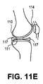
(00014) 本発明の一態様は、例えば、肩鎖関節、足首関節、関節丘、肘関節、指関節、関節窩、股関節、椎間板、椎間板椎間関節、関節唇、半月板、中手骨関節、中足骨関節、膝蓋骨、脛骨プラトー、足指関節、顎関節、又は手首関節に適合するように構成され、骨接触表面を有する骨界面部材(bone interface member)と、ベアリング表面及び付着区域を有する水膨潤性IPN又は半IPN部材とを含む、整形外科用インプラントを提供するものであり、この付着区域は、骨界面部材に付着しており、水膨潤性IPN又は半IPN部材は、ベアリング表面と付着区域との間で組成勾配を示すように構成された疎水性の熱硬化性又は熱可塑性ポリマーの第1のネットワークとイオン性ポリマーの第2のネットワークとを含む。いくつかの実施形態において、インプラントの組成勾配は、剛性勾配を形成する。いくつかの実施形態において、ネットワークのうちの1つは、インプラントの第1の部分からインプラントの第2の部分への水和勾配を形成する。 [00014] One embodiment of the present invention is, for example, acromioclavicular joint, ankle joint, condyle, elbow joint, finger joint, glenoid, hip joint, intervertebral disc, intervertebral disc facet joint, joint lip, meniscus, metacarpal joint A bone interface member configured to fit a metatarsal joint, patella, tibial plateau, toe joint, temporomandibular joint, or wrist joint, a bone interface member, a bearing surface and an attachment area An orthopedic implant comprising a water-swellable IPN or semi-IPN member having the attachment area attached to the bone interface member, wherein the water-swellable IPN or semi-IPN member is a bearing surface. A first network of hydrophobic thermosetting or thermoplastic polymers and a second network of ionic polymers configured to exhibit a composition gradient between the first and second deposition zones. In some embodiments, the composition gradient of the implant forms a stiffness gradient. In some embodiments, one of the networks forms a hydration gradient from the first portion of the implant to the second portion of the implant.
(00015) いくつかの実施形態において、骨界面部材は、金属(例えば、多孔性金属)を含む。いくつかの実施形態において、骨界面部材は、セラミック又はポリマーを含む。いくつかの実施形態において、整形外科用関節の少なくとも一部は、形状を変化させるか、又は関節内でのインプラント配置時に一過性に屈曲するように構成されている。 [00015] In some embodiments, the bone interface member comprises a metal (eg, a porous metal). In some embodiments, the bone interface member comprises a ceramic or polymer. In some embodiments, at least a portion of the orthopedic joint is configured to change shape or bend temporarily upon placement of the implant within the joint.
(00016) 第1のネットワークがポリウレタンを含むいくつかの実施形態において、インプラントは、IPN又は半IPN部材と骨界面部材(bone interfacing member)との間に化学結合(例えば、ウレタン結合)を含む。いくつかの実施形態において、付着区域の骨界面部材への付着は、接着剤によって生成される。 [00016] In some embodiments, where the first network includes polyurethane, the implant includes a chemical bond (eg, a urethane bond) between the IPN or semi-IPN member and the bone interfacing member. In some embodiments, the attachment of the attachment area to the bone interface member is generated by an adhesive.
(00017) いくつかの実施形態において、イオン性ポリマーの第2のネットワークは固定電荷を有し、かつカルボン酸基及び/又はスルホン酸基を更に含むことができる。 [00017] In some embodiments, the second network of ionic polymers has a fixed charge and can further comprise carboxylic acid groups and / or sulfonic acid groups.
(00018) いくつかの実施形態において、IPN又は半IPNの厚さは、最も厚い領域において5mm未満である。 (00018) In some embodiments, the thickness of the IPN or semi-IPN is less than 5 mm in the thickest region.
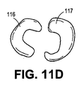
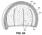
(00019) いくつかの実施形態において、インプラントは、合成関節包を更に含むことができ、かつ流体を含むことができる。いくつかの実施形態において、インプラントは、関節唇コンポーネントを更に含んでいてもよい。いくつかの実施形態において、インプラントは、キャップ、カップ、プラグ、マッシュルーム、パッチ、及び/又はステムの形状を有することができる。 [00019] In some embodiments, the implant can further include a synthetic joint capsule and can include a fluid. In some embodiments, the implant may further include an articular lip component. In some embodiments, the implant can have the shape of a cap, cup, plug, mushroom, patch, and / or stem.
(00020) 本発明のまた別の態様は、疎水性の熱硬化性又は熱可塑性ポリマーとイオン性ポリマーとを含む水膨潤性IPN又は半IPNを含む第1の医療用インプラントを含む整形外科用インプラントシステムを提供するものであり、第1の医療用インプラントは、骨表面に適合するように構成された骨接触表面及び別のインプラントのベアリング表面と嵌合するように構成されたベアリング表面又はベアリング表面を包囲するように構成された天然の関節及び関節包を有する。いくつかの実施形態において、関節包は、流体を含む。 [00020] Another aspect of the present invention is an orthopedic implant comprising a first medical implant comprising a water-swellable IPN or semi-IPN comprising a hydrophobic thermosetting or thermoplastic polymer and an ionic polymer. A system or system wherein a first medical implant is configured to mate with a bone contacting surface configured to conform to a bone surface and a bearing surface of another implant. Natural joints and joint capsules configured to surround the body. In some embodiments, the joint capsule includes a fluid.
(00021) いくつかの実施形態において、このシステムは、疎水性の熱硬化性又は熱可塑性ポリマーとイオン性ポリマーとを含む水膨潤性IPN又は半IPNを含む第2の医療用インプラントを更に含み、第2の医療用インプラントは、骨表面及びベアリング表面に適合するように構成された骨接触表面を有しており、第1の医療用インプラントは、関節の1つの側に配置するように構成されていてもよく、第2の医療用インプラントは、関節の第2の側に配置するように構成されており、第1の医療用インプラント及び第2の医療用インプラントのベアリング表面は、嵌合するように構成されており、関節包は、第1の医療用インプラント及び第2の医療用インプラントのベアリング表面を包囲するように構成されていてもよい。 (00021) In some embodiments, the system further comprises a second medical implant comprising a water-swellable or semi-IPN comprising a hydrophobic thermosetting or thermoplastic polymer and an ionic polymer; The second medical implant has a bone contacting surface configured to conform to the bone surface and the bearing surface, and the first medical implant is configured to be disposed on one side of the joint. The second medical implant is configured to be disposed on the second side of the joint, and the bearing surfaces of the first medical implant and the second medical implant are mated. And the joint capsule may be configured to surround the bearing surfaces of the first medical implant and the second medical implant.
(00022) いくつかの実施形態において、整形外科用インプラントシステムは、IPN又は半IPNに物理的に付着した骨界面部材を更に含み、骨界面部材は、骨接触表面を含み、かつ金属であることができる。 [00022] In some embodiments, the orthopedic implant system further comprises a bone interface member physically attached to the IPN or semi-IPN, wherein the bone interface member includes a bone contacting surface and is metal. Can do.
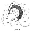
(00023) 本発明のまた別の態様は、疎水性の熱硬化性又は熱可塑性ポリマーとイオン性ポリマーとを含む水膨潤性IPN又は半IPNを含む股関節インプラントを提供するものであり、インプラントは、骨表面に適合するように構成された骨接触表面、ベアリング表面、及びベアリング表面を包囲するように構成された関節唇コンポーネントを有する。 [00023] Yet another aspect of the present invention provides a hip implant comprising a water-swellable IPN or semi-IPN comprising a hydrophobic thermosetting or thermoplastic polymer and an ionic polymer, the implant comprising: A bone contacting surface configured to conform to the bone surface, a bearing surface, and an articular lip component configured to surround the bearing surface.
(00024) いくつかの実施形態において、股関節インプラントは、流体を含み、かつベアリング表面を包囲するように構成された関節包を更に含む。 [00024] In some embodiments, the hip implant further includes a joint capsule that includes fluid and is configured to surround the bearing surface.
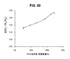
(00025) 本発明のまた別の態様は、pH7.4、37℃、0.9%水性塩溶液中で分析したとき、約4%〜約90%(w/w)のポリウレタン、約1%〜約40%(w/w)のポリアクリル酸の電解質、及び約3%〜約80%の水を含むポリウレタン−ポリアクリル酸IPN又は半IPNを含む物質の組成物を提供する。いくつかの実施形態において、ポリウレタンの濃度は、約8%〜約55%であり、ポリアクリル酸の電解質の組成は、約9%〜約22%であり、かつ/又は水の濃度は、約25%〜約80%である。 [00025] Yet another aspect of the present invention is from about 4% to about 90% (w / w) polyurethane, about 1% when analyzed in 0.9% aqueous salt solution at pH 7.4, 37 ° C. A composition of matter comprising a polyurethane-polyacrylic acid IPN or semi-IPN comprising about 40% (w / w) polyacrylic acid electrolyte and about 3% to about 80% water is provided. In some embodiments, the polyurethane concentration is about 8% to about 55%, the polyacrylic acid electrolyte composition is about 9% to about 22%, and / or the water concentration is about 25% to about 80%.
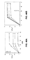
(00026) 本発明のまた別の態様は、ベアリング表面及び付着表面を有し、かつ疎水性の熱硬化性又は熱可塑性ポリマーの第1のネットワークとイオン性ポリマーの第2のネットワークとを含む水膨潤性IPN又は半IPNを含む整形外科用インプラントを提供するものであり、ベアリング表面は、0.001〜0.1の摩擦係数、0.8〜200MPaの平衡圧縮弾性係数、25%〜80%の水含有量、10-17m4/N秒を超える透水率、及び10%を超える破損引張ひずみを有する。いくつかの実施形態において、整形外科用インプラントは、50%を超える破損引張ひずみを有する。 [00026] Another aspect of the present invention is a water having a bearing surface and an attachment surface and comprising a first network of hydrophobic thermosetting or thermoplastic polymers and a second network of ionic polymers. An orthopedic implant comprising a swellable or semi-IPN is provided, wherein the bearing surface has a friction coefficient of 0.001 to 0.1, an equilibrium compression modulus of 0.8 to 200 MPa, 25% to 80%. Having a water content of greater than 10 −17 m 4 / N seconds, and a tensile failure strain greater than 10%. In some embodiments, the orthopedic implant has a failure tensile strain greater than 50%.
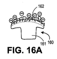
(00027) 本発明のまた別の態様は、ベアリング表面及び付着区域(例えば、錐体状構造、くぼみ、溝、くい、支柱、ピン、及びピラミッド状構造などの特色)を含むポリマーベアリング部材と、このポリマーベアリング部材の付着区域に付着し、かつ金属及び金属中の空間を含む骨界面部材とを含む整形外科用インプラントを提供するものであり、この整形外科用インプラントは、骨界面部材を骨表面に適合させるように、第1の形状から第2の形状へと変形可能である。 [00027] Another aspect of the present invention is a polymer bearing member comprising a bearing surface and an attachment area (eg, features such as cone-like structures, indentations, grooves, rakes, posts, pins, and pyramid-like structures); An orthopedic implant is provided that includes a bone interface member that adheres to an attachment area of the polymer bearing member and includes a metal and a space in the metal, the orthopedic implant that attaches the bone interface member to a bone surface. The first shape can be changed to the second shape so as to be adapted to the above.
(00028) いくつかの実施形態において、整形外科用インプラント内の空間は、金属内の空孔(pores)又はスロットを含む。いくつかの実施形態において、整形外科用インプラントは、付着表面に付着し、かつ互いに分離されている複数の金属部材を含む。 [00028] In some embodiments, the space within the orthopedic implant includes pores or slots in the metal. In some embodiments, the orthopedic implant includes a plurality of metal members attached to the attachment surface and separated from each other.
(00029) いくつかの実施形態において、骨界面部材は、例えば、ポリマーベアリング部材と骨界面部材との間の化学結合によって、ポリマーベアリング部材に物理的に付着している。いくつかの実施形態において、付着区域の骨界面部材への付着は、接着剤によって生成される。 [00029] In some embodiments, the bone interface member is physically attached to the polymer bearing member, for example, by a chemical bond between the polymer bearing member and the bone interface member. In some embodiments, the attachment of the attachment area to the bone interface member is generated by an adhesive.
(00030) いくつかの実施形態において、ポリマーベアリング部材は、水膨潤性IPN又は半IPNを含み、かつ疎水性の熱硬化性又は熱可塑性ポリマーの第1のネットワークとイオン性ポリマーの第2のネットワークとを含むことができる。 [00030] In some embodiments, the polymer bearing member comprises a water-swellable IPN or semi-IPN, and a first network of hydrophobic thermosetting or thermoplastic polymers and a second network of ionic polymers Can be included.
(00031) 本発明のまた別の態様は、整形外科用インプラントを関節内に挿入する方法を含み、このインプラントは、金属部分と、付着区域及びベアリング表面を有する可撓性ポリマー部分とを含み、この金属部分は、付着区域に付着しており、この方法は、第1の形状のインプラントを関節内に挿入する工程、及び関節を形成する骨の少なくとも一部の形状を適合させるためにインプラントを第1の形状から第2の形状に変化させる工程を含む。いくつかの実施形態において、この方法は、第1の変化させる工程の後に、インプラントを第2の形状から第1の形状に戻す工程を更に含む。他の実施形態において、この方法は、変化させる工程の前に、インプラントをもとの形状から第1の形状に変形させる工程を含む。関節が股関節であり、インプラントが股関節の大腿骨頭に配置されるように構成されているいくつかの実施形態において、変形させることは、大腿骨頭に適合するようにインプラントの一部を拡張することを含む。
本発明の新規の特色は、以下の特許請求の範囲において具体的に認識される。本発明の特色及び利点のより良好な理解は、本発明の原理が利用される例示的な実施形態を記載する以下の詳細な説明、及び添付の図面を参照することによって得られるであろう。
[00031] Another aspect of the invention includes a method of inserting an orthopedic implant into a joint, the implant including a metal portion and a flexible polymer portion having an attachment area and a bearing surface; The metal portion is attached to the attachment area, and the method includes inserting the first shape implant into the joint and adapting the implant to match the shape of at least a portion of the bone forming the joint. Changing the first shape to the second shape. In some embodiments, the method further includes returning the implant from the second shape to the first shape after the first changing step. In other embodiments, the method includes the step of deforming the implant from the original shape to the first shape prior to the changing step. In some embodiments where the joint is a hip joint and the implant is configured to be placed on the femoral head of the hip joint, deforming will expand a portion of the implant to fit the femoral head. Including.
The novel features of the invention are specifically recognized in the following claims. A better understanding of the features and advantages of the present invention will be obtained by reference to the following detailed description that sets forth illustrative embodiments, in which the principles of the invention are utilized, and the accompanying drawings of which:
(000113) 本発明は、疎水性の熱硬化性又は熱可塑性ポリマーを修飾して、それらに、潤滑性、透過性、伝導性、及び耐摩耗性などの品質を付与する工程を含む。そのような疎水性ポリマーは、通常、それほど顕著な程度には水を吸収せず、また通常、その機械的強度、不透過性、及び絶縁能力のために有用である。本発明の工程により修飾可能な一般的でかつ市販されている疎水性ポリマーの例示的なリストには、以下のものが含まれる:アクリロニトリルブタジエンスチレン(ABS)、ポリメチルメタクリレート(PMMA)、アクリル、セルロイド、セルロースアセテート、エチレン−ビニルアセテート(EVA)、エチレンビニルアルコール(EVAL)、商標登録されたアクリル/PVCアロイであるKydex、液晶ポリマー(LCP)、ポリアセタール(POM又はアセタール)、ポリアクリレート(アクリル)、ポリアクリロニトリル(PAN又はアクリロニトリル)、ポリアミド(PA又はナイロン)、ポリアミド−イミド(PAI)、ポリアリールエーテルケトン(PAEK又はケトン)、ポリヒドロキシアルカノエート(PHA)、ポリケトン(PK)、ポリエステル、ポリエーテルエーテルケトン(PEEK)、ポリエーテルイミド(PEI)、ポリエーテルスルホン(PES)−例えば、ポリスルホン、ポリエチレンクロリネート(PEC)、ポリイミド(PI)、ポリメチルペンテン(PMP)、ポリフェニレンオキシド(PPO)、ポリフェニレンスルフィド(PPS)、ポリフタルアミド(PPA)、ポリスチレン(PS)、ポリスルホン(PSU)、ポリビニルアセテート(PVA)、ポリ塩化ビニル(PVC)、ポリ塩化ビニリデン(PVDC)、スペクトラロン、スチレン−アクリロニトリル(SAN)、ポリジメチルシロキサン(PDMS)、及びポリウレタン(PU)。他のあまり一般的でなくかつ市販されていない(すなわち、特注の)ポリマーを使用することもできる。本明細書に記載されているように、多種多様なポリウレタンを、ハードセグメント、ソフトセグメント、及び鎖伸長剤の組成を変えて使用することができる。 [000113] The present invention includes the steps of modifying hydrophobic thermosetting or thermoplastic polymers to impart qualities such as lubricity, permeability, conductivity, and abrasion resistance to them. Such hydrophobic polymers typically do not absorb water to a significant extent and are usually useful because of their mechanical strength, impermeability, and insulating ability. An exemplary list of common and commercially available hydrophobic polymers that can be modified by the process of the present invention includes: acrylonitrile butadiene styrene (ABS), polymethyl methacrylate (PMMA), acrylic, Celluloid, cellulose acetate, ethylene-vinyl acetate (EVA), ethylene vinyl alcohol (EVAL), Kydex which is a registered acrylic / PVC alloy, liquid crystal polymer (LCP), polyacetal (POM or acetal), polyacrylate (acrylic) , Polyacrylonitrile (PAN or acrylonitrile), polyamide (PA or nylon), polyamide-imide (PAI), polyaryletherketone (PAEK or ketone), polyhydroxyalkanoate (PHA) Polyketone (PK), polyester, polyetheretherketone (PEEK), polyetherimide (PEI), polyethersulfone (PES)-for example, polysulfone, polyethylene chlorinate (PEC), polyimide (PI), polymethylpentene (PMP) ), Polyphenylene oxide (PPO), polyphenylene sulfide (PPS), polyphthalamide (PPA), polystyrene (PS), polysulfone (PSU), polyvinyl acetate (PVA), polyvinyl chloride (PVC), polyvinylidene chloride (PVDC) , Spectralon, styrene-acrylonitrile (SAN), polydimethylsiloxane (PDMS), and polyurethane (PU). Other less common and non-commercially available (ie custom-made) polymers can also be used. As described herein, a wide variety of polyurethanes can be used with varying hard segment, soft segment, and chain extender compositions.
(000114) 本発明の一態様は、いくつかの修飾可能な熱硬化性又は熱可塑性の疎水性ポリマーの特徴:ポリマー内での規則性ドメイン及び非規則性(非晶質)ドメインの存在を利用する。例えば、ポリウレタンなどのいくつかの疎水性の熱硬化性又は熱可塑性ポリマーは相分離し、ハードセグメントの第1のドメイン及びソフトセグメントの第2のドメインを含有し、2つのドメインは、モノマーの相互透過性に関して異なる溶解性特性を示す。ポリウレタンにおいて、ハードセグメントは主として規則性ドメイン内に配置され、ソフトセグメントは主として非規則性(非晶質)ドメイン内に配置される。(出発ポリマーは、当然、本発明の範囲を逸脱することなく、3以上のドメインを含有することができる。)相分離ポリマーの2つのドメイン間のこの特性の違いによって、本発明の工程は、材料のバルクにわたって、又は材料の一部のみにわたって、例えば、特定の領域中で、又は勾配中で伸長することができる新しい特性をポリマーに付与することが可能になる。例えば、非潤滑性ポリマーを潤滑性にすることができ;そのままでは非伝導性のポリマーを伝導性にすることができ;かつそのままでは非透過性のポリマーを透過性にすることができる。更に、工程を反復して行ない、2以上の新しい特性を出発ポリマーに導入することができる。 [000114] One aspect of the present invention utilizes the characteristics of several modifiable thermosetting or thermoplastic hydrophobic polymers: the presence of regular and non-regular (amorphous) domains within the polymer. To do. For example, some hydrophobic thermoset or thermoplastic polymers such as polyurethane phase separate and contain a hard domain first domain and a soft segment second domain, the two domains being monomeric Different solubility characteristics with respect to permeability. In polyurethane, hard segments are mainly arranged in regular domains and soft segments are mainly arranged in non-regular (amorphous) domains. (The starting polymer can of course contain more than two domains without departing from the scope of the invention.) Due to this difference in properties between the two domains of the phase separated polymer, the process of the invention It makes it possible to impart new properties to the polymer that can be stretched over the bulk of the material or over only a part of the material, for example in a specific region or in a gradient. For example, a non-lubricating polymer can be made lubricious; as such, a non-conductive polymer can be made conductive; and as it is, a non-permeable polymer can be made permeable. Furthermore, the process can be repeated to introduce two or more new properties into the starting polymer.
(000115) いくつかの実施形態において、ポリマー中での相分離は、例えば、溶媒及び/又はモノマーによるポリマー内の1以上の分離相の示差膨潤を可能にし、その後、それを用いて、新しい特性を付与する。本発明によれば、例えば、イオン性モノマーを付加し、重合させることによって、そのままでは潤滑性でない材料に潤滑さを導入することができる。一実施形態において、高い機械的強度と潤滑性の表面とを有するポリマー材料を、イオン化可能なビニルモノマーに由来するそのままでは潤滑性でない疎水性ポリマー及び親水性ポリマーから作製ことができる。そのままでは疎水性の材料を固相と液(水)相の両方を有する二相材料に変換することによって、本発明は、医療、商業、及び工業用途で使用するための、潤滑性で、高強度の材料に対する当技術分野における必要性に対処する。 [000115] In some embodiments, phase separation in the polymer allows for differential swelling of one or more separated phases in the polymer, for example by solvents and / or monomers, which can then be used to generate new properties. Is granted. According to the present invention, for example, by adding an ionic monomer and polymerizing it, lubricity can be introduced into a material that is not lubricious as it is. In one embodiment, polymeric materials having high mechanical strength and lubricious surfaces can be made from hydrophobic and hydrophilic polymers that are not naturally lubricious derived from ionizable vinyl monomers. By converting a hydrophobic material as it is into a two-phase material having both a solid phase and a liquid (water) phase, the present invention provides a lubricious, high performance for use in medical, commercial, and industrial applications. Address the need in the art for strong materials.
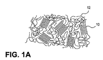
(000116) 図1A〜Dは、ハードセグメント10(白い長方形として示されている)とソフトセグメント12(線として示されている)のネットワークを含む熱可塑性ポリウレタン系ポリマーに関する工程を示す。図1Bにおいて、ソフトセグメント12は、開始剤及び架橋剤(図示せず)とともに、ビニル系モノマー14(丸として示されている)及び任意の溶媒で膨潤するが、ハードセグメント材料はほとんど影響されない。この膨潤工程は、ポリマーの溶解ではなく;ハードセグメントは、ソフトセグメントがモノマー及び任意の溶媒を吸収するとき、材料を結び付ける物理的な架橋として作用する。モノマーの重合及び架橋の後、第2のネットワーク16(図1C及び1Dで太線として示されている)が、第1のネットワークの存在下で形成され、第1のポリマーの柔軟な非晶質ドメイン内に第2のポリマー(すなわち、重合モノマー)が主として隔離されたIPNが生成される。ある程度の分子内転位及び更なる相分離があるにもかかわらず、ハードセグメントは、大部分、規則性かつ結晶性のままであり、材料に構造及び強度を提供する。
[000116] FIGS. 1A-D show the steps for a thermoplastic polyurethane-based polymer comprising a network of hard segments 10 (shown as white rectangles) and soft segments 12 (shown as lines). In FIG. 1B, the
(000117) このIPNによって提供される新しい特性は、導入された重合モノマーの特性及び何らかの任意の重合後処理によって決まる。そのような新しい特性の例としては、潤滑さ、伝導性、硬さ、吸収性、透過性、光反応性、及び熱反応性が挙げられる。例えば、図1Dに示されるように、緩衝水溶液中での任意の膨潤の後、図1CのIPNの第2のネットワークはイオン化されたもの18となり、IPNは、水膨潤性及び潤滑性になる。従って、親水性(すなわち、吸水性)を、そのままでは疎水性の材料に導入することができる。ポリウレタン又はABSなどの疎水性ポリマー材料に、それが水を吸収するように、ポリアクリル酸及び/又はポリ(メタクリル酸スルホプロピル)などの様々なイオン性ポリマーを浸透させることができる。 [000117] The new properties provided by this IPN depend on the properties of the introduced polymerization monomers and any optional post-polymerization treatment. Examples of such new properties include lubricity, conductivity, hardness, absorption, transmission, photoreactivity, and thermal reactivity. For example, as shown in FIG. 1D, after optional swelling in a buffered aqueous solution, the second network of IPN of FIG. 1C becomes ionized 18 and the IPN becomes water swellable and lubricious. Accordingly, hydrophilicity (that is, water absorption) can be introduced into a hydrophobic material as it is. Various ionic polymers such as polyacrylic acid and / or poly (sulfopropyl methacrylate) can be impregnated into a hydrophobic polymer material such as polyurethane or ABS so that it absorbs water.
(000118) 吸収性に加えて、様々なレベルの透過性(水、イオン、及び/又は溶質の輸送)を、そのままでは非透過性の材料に導入することができる。例えば、上記のように、ポリウレタン又はABSなどの疎水性ポリマー材料に、それが水を吸収するように、ポリアクリル酸及び/又はポリ(メタクリル酸スルホプロピル)などのイオン性ポリマーを浸透させることができる。材料のバルクのこの水和は、溶質及びイオンの輸送を可能にする。溶質及びイオンの輸送並びに水に対する透過性は、IPNの水和相の相連続性によって可能になる。これは、薬物送達、分離工程、プロトン交換膜、及び触媒工程を含む様々な用途において有用である。透過性を利用して、液体が材料にわたって又は材料を通って流れるときに、溶質を捕捉、濾過、又はキレート化することもできる。更に、この透過性があるので、本発明の材料は、持続的又は反復的荷重の後に流体を再吸収するその能力のために、その成分疎水性ポリマーと比べて、クリープ抵抗性及び疲労抵抗性を増大させることができる。 [000118] In addition to absorbency, various levels of permeability (water, ion, and / or solute transport) can be introduced into non-permeable materials as they are. For example, as described above, a hydrophobic polymer material such as polyurethane or ABS can be impregnated with an ionic polymer such as polyacrylic acid and / or poly (sulfopropyl methacrylate) so that it absorbs water. it can. This hydration of the bulk of the material allows for the transport of solutes and ions. Solute and ion transport and water permeability are enabled by the phase continuity of the hydrated phase of IPN. This is useful in a variety of applications including drug delivery, separation processes, proton exchange membranes, and catalytic processes. Permeability can also be used to trap, filter, or chelate solutes as the liquid flows across or through the material. In addition, because of this permeability, the material of the present invention is creep resistant and fatigue resistant compared to its component hydrophobic polymers due to its ability to resorb fluid after sustained or repeated loading. Can be increased.
(000119) 伝導性を、他の非伝導性の材料に導入することができる。例えば、ハイブリッド材料の少なくとも一部が電流に対して伝導性となるように、ポリウレタンなどの絶縁ポリマー材料に、伝導性ポリマー(多価電解質)を浸透させることができる。 [000119] Conductivity can be introduced into other non-conductive materials. For example, a conductive polymer (polyelectrolyte) can be infiltrated into an insulating polymer material such as polyurethane so that at least a portion of the hybrid material is conductive to current.
(000120) 本発明は、第2のポリマーの化学基の改変、及び別のポリマー、分子、又は生体分子に対する第2のポリマー中の連結点の使用も含む。また、ドメインのいずれかに、抗酸化剤、イオン、イオノマー、造影剤、粒子、金属、顔料、染料、生体分子、ポリマー、タンパク質、及び/又は治療剤などの、任意の数の材料をドープすることができる。 [000120] The present invention also includes the modification of the chemical groups of the second polymer and the use of attachment points in the second polymer relative to another polymer, molecule, or biomolecule. Also, any of the domains is doped with any number of materials such as antioxidants, ions, ionomers, contrast agents, particles, metals, pigments, dyes, biomolecules, polymers, proteins, and / or therapeutic agents. be able to.
(000121) 例えば、アクリルオキシ、メタクリルオキシ−アクリルアミド−、アリルエーテル、又はビニル官能基が、ポリウレタンプレポリマーの一端又は両端に取り込まれている場合、第1のポリマーを第2のポリマーと更に架橋又は共重合させ、その後、開始剤の存在下でUV又は温度によって硬化させることができる。例えば、ポリウレタンジメタクリレート又はポリウレタンビスアクリルアミドは、溶媒(例えば、ジメチルアセトアミド)の存在下で硬化させ、その後、溶媒を蒸発させることによって、第1のネットワーク中で使用することができる。IPNへの化学的架橋(単なる物理的架橋ではない)の付加は、連続的な動的荷重によって生じるクリープ又は疲労に対するあるレベルの機械的安定性を付加する。 [000121] For example, if an acryloxy, methacryloxy-acrylamide-, allyl ether, or vinyl functional group is incorporated at one or both ends of the polyurethane prepolymer, the first polymer is further crosslinked or cross-linked with the second polymer. It can be copolymerized and then cured by UV or temperature in the presence of an initiator. For example, polyurethane dimethacrylate or polyurethane bisacrylamide can be used in the first network by curing in the presence of a solvent (eg, dimethylacetamide) and then evaporating the solvent. The addition of chemical crosslinks (not just physical crosslinks) to the IPN adds some level of mechanical stability to creep or fatigue caused by continuous dynamic loading.
(000122) 更に、多腕(多官能性)ポリオール又はイソシアネートを用いて、ポリウレタン中で架橋を生成させることができる。この場合、(半相互透過性ポリマーネットワークではなく)完全相互透過性ポリマーネットワークが生成される。結果は、ポリウレタンの高い強度及び靱性、並びにポリ(アクリル酸)の潤滑性表面及び二相性バルク挙動を有する複合材料である。或いは、限定されないが、ガンマ線又は電子ビーム放射線を含む、他の架橋方法を使用することができる。これらの特色は、人工関節表面などのベアリング用途のために、又は血管系もしくは皮膚などの身体の他の領域におけるより生体適合性で、血栓抵抗性の長期インプラントとして特に重要である。水で膨潤させることにより、身体の標的領域への局所的送達のための治療剤又は治療薬などの溶質の吸収も可能になる。 [000122] Furthermore, cross-links can be generated in polyurethanes using multi-arm (polyfunctional) polyols or isocyanates. In this case, a fully interpermeable polymer network (rather than a semi-interpenetrating polymer network) is produced. The result is a composite material with the high strength and toughness of polyurethane and the lubricious surface and biphasic bulk behavior of poly (acrylic acid). Alternatively, other crosslinking methods can be used, including but not limited to gamma rays or electron beam radiation. These features are particularly important for bearing applications such as artificial joint surfaces or as more biocompatible, thromboresistant long-term implants in other areas of the body such as the vasculature or skin. Swelling with water also allows the absorption of solutes such as therapeutic agents or therapeutic agents for local delivery to a target area of the body.
(000123) 本発明の別の実施形態において、第1のポリマーを第2のポリマーに結合させることができる。例えば、ポリウレタンを、ビニル末端基を介して結合させることができる。末端基と重合中のモノマーとの間の反応性比によって、様々な鎖立体形状を生じさせることができる。例えば、モノマーとそれ自体との反応性が、末端基とモノマーよりもはるかに大きい場合、第1のポリマーが鎖に付加される前に、第2のポリマーがほぼ完全に形成される。他方、モノマーと末端基の反応性が類似している場合、ランダムグラフト型の共重合が起こる。モノマー及び末端基は、例えば、The Polymer Handbookに公表されている相対的反応性比の表を用いることによって、その反応性比に基づいて選択することができる。これらの結果は、ハイブリッドコポリマー/相互透過性ポリマーネットワークである。 [000123] In another embodiment of the invention, a first polymer can be attached to a second polymer. For example, polyurethane can be attached through vinyl end groups. Depending on the reactivity ratio between the end group and the monomer being polymerized, various chain configurations can be produced. For example, if the reactivity of the monomer with itself is much greater than the end group and the monomer, the second polymer is almost completely formed before the first polymer is added to the chain. On the other hand, when the reactivity of the monomer and the end group is similar, random graft type copolymerization occurs. Monomers and end groups can be selected based on their reactivity ratios, for example, by using a table of relative reactivity ratios published in The Polymer Handbook. These results are a hybrid copolymer / interpenetrating polymer network.
(000124) 任意の数又は組合せのエチレン系不飽和モノマー又はマクロモノマー(すなわち、反応性二重結合/ビニル基を有する)を、単独で又は様々な溶媒と組み合わせて使用することができ、かつそのようなモノマーの少なくとも2%がイオン化可能である限り、すなわち、カルボン酸及び/又はスルホン酸官能基を含有する限り、ポリマーの相のうちの1つ又は複数に選択的に導入することができる。他のモノマーとしては、ジメチルアクリルアミド、アクリルアミド、NIPAAm、アクリル酸メチル、メタクリル酸メチル、ヒドロキシエチルアクリレート/メタクリレート、及びスルホン酸基を含有する任意のビニル系モノマー(例えば、アクリルアミドメチルプロパンスルホン酸、ビニルスルホン酸、3−スルホプロピルアクリレート(もしくはメタクリレート)、2−メチル−2−プロペン−1−スルホン酸ナトリウム塩98%、又はスルホン酸が共役している任意のモノマー(アリルエーテル、アクリレート/メタクリレート、ビニル基、もしくはアクリルアミド)が挙げられるが、これらに限定されない。モノマーとしては、アリルエーテル、アクリレート/メタクリレート、ビニル基、又はアクリルアミドに共役したカルボン酸基を含有する任意のモノマーを挙げることもできる。更に、モノマーを、カルボキシル酸とスルホン酸の両方を含有するモノマーなどの組合せで用いて、カルボキシレート/スルホネートコポリマーを生成させることができる。これらのモノマー及びモノマー組合せから得られるポリマー上のペンダント官能基を後続の化学反応に供して、他の官能基を最終的なポリマーに与えることができる。 [000124] Any number or combination of ethylenically unsaturated monomers or macromonomers (ie, having reactive double bonds / vinyl groups) can be used alone or in combination with various solvents, and As long as at least 2% of such monomers are ionizable, ie, contain carboxylic acid and / or sulfonic acid functional groups, they can be selectively introduced into one or more of the polymer phases. Other monomers include dimethylacrylamide, acrylamide, NIPAAm, methyl acrylate, methyl methacrylate, hydroxyethyl acrylate / methacrylate, and any vinyl monomer containing sulfonic acid groups (eg, acrylamide methylpropane sulfonic acid, vinyl sulfone). Acid, 3-sulfopropyl acrylate (or methacrylate), 2-methyl-2-propene-1-sulfonic acid sodium salt 98%, or any monomer conjugated with sulfonic acid (allyl ether, acrylate / methacrylate, vinyl group) Or acrylamide), but the monomers include allyl ether, acrylate / methacrylate, vinyl groups, or carboxylic acid conjugated to acrylamide. Mention may also be made of any monomers containing groups, and the monomers may be used in combination, such as monomers containing both carboxylic and sulfonic acids, to form carboxylate / sulfonate copolymers. Pendant functional groups on the polymer resulting from the monomer and monomer combination can be subjected to subsequent chemical reactions to provide other functional groups to the final polymer.
(000125) 一実施形態において、予備形成された熱可塑性ポリマーを、モノマーに対して約0.1%v/vの架橋剤(例えば、トリエチレングリコールジメタクリレート又はN,Nメチレンビスアクリルアミド)及びモノマーに対して約0.1%v/vの光開始剤(例えば、2−ヒドロキシ−2−メチルプロピオフェノン)とともに、アクリル酸(又はアクリル酸の溶液(1%〜100%)もしくは他のビニルモノマー溶液)に浸漬させることができる。アクリル酸溶液は、水、塩緩衝液、又は有機溶媒、例えば、ジメチルアセトアミド、アセトン、エタノール、メタノール、イソプロピルアルコール、トルエン、ジクロロメタン、プロパノール、ジメチルスルホキシド、ジメチルホルムアミド、又はテトラヒドロフランに基づくことができる。ポリマーは、ポリマー中のソフトセグメントの溶媒和のために、モノマーによって膨潤させることができる。膨潤したポリマー中のモノマー含有量は、わずか約1%から最大約90%までの範囲であることができる。 [000125] In one embodiment, the preformed thermoplastic polymer is about 0.1% v / v crosslinker (eg, triethylene glycol dimethacrylate or N, N methylene bisacrylamide) and monomer to monomer. Acrylic acid (or a solution of acrylic acid (1% to 100%) or other vinyl with about 0.1% v / v photoinitiator (eg 2-hydroxy-2-methylpropiophenone) relative to Monomer solution). The acrylic acid solution can be based on water, salt buffer, or organic solvents such as dimethylacetamide, acetone, ethanol, methanol, isopropyl alcohol, toluene, dichloromethane, propanol, dimethylsulfoxide, dimethylformamide, or tetrahydrofuran. The polymer can be swollen by the monomer due to the solvation of the soft segments in the polymer. The monomer content in the swollen polymer can range from as little as about 1% up to about 90%.
(000126) その後、モノマーにより膨潤したポリマーを取り出し、ガラス、石英、又は透明なポリマーでできた型に入れ、その後、UV光(又は高温)に曝露させて、モノマーの重合及び架橋を開始させることができる。或いは、型を使用する代わりに、空気又は不活性雰囲気(例えば、窒素もしくはアルゴン)に完全に又は部分的に曝露させながら、或いは油(例えば、パラフィン、鉱油、又はシリコーン油)などの別の液体の存在下で、モノマーにより膨潤したポリマーを重合させることができる。医療用途のために、重合工程を、型なしでインビボで実施することができる可能性がある。 (000126) The polymer swollen by the monomer is then removed and placed in a mold made of glass, quartz, or a transparent polymer, and then exposed to UV light (or high temperature) to initiate polymerization and crosslinking of the monomer. Can do. Alternatively, instead of using a mold, another liquid such as oil (eg paraffin, mineral oil, or silicone oil) with full or partial exposure to air or an inert atmosphere (eg nitrogen or argon) In the presence of the polymer, the polymer swollen by the monomer can be polymerized. For medical applications, it may be possible to carry out the polymerization process in vivo without a mold.
(000127) 使用される開始剤によって、UV光、IR、もしくは可視光、化学物質、電荷、又は高温への曝露は、疎水性ポリマー内でのイオン化可能モノマーの重合及び架橋をもたらす。一例として、酸性モノマー(例えば、アクリル酸)を重合させると、予備形成された熱可塑性の疎水性マトリックス内でイオン性ポリマーが形成され、相互透過性ポリマーネットワーク(「IPN」)が形成される。溶媒は、熱及び対流によるか、又は溶媒抽出によって抽出することができる。溶媒抽出は、異なる溶媒(例えば、水)を用いて、溶媒をポリマーから抽出することを含むのに対し、熱又は対流は、溶媒の蒸発に依存する。イオン性ポリマーのpKa(例えば、PAAのpKa=4.7)によって、酸性pHがイオン性ポリマーをよりプロトン化させる一方、より塩基性のpHは、それをよりイオン化させる。 [000127] Depending on the initiator used, exposure to UV light, IR, or visible light, chemicals, charge, or high temperature results in the polymerization and crosslinking of ionizable monomers within the hydrophobic polymer. As an example, polymerizing an acidic monomer (eg, acrylic acid) forms an ionic polymer within a preformed thermoplastic hydrophobic matrix, forming an interpenetrating polymer network (“IPN”). The solvent can be extracted by heat and convection or by solvent extraction. Solvent extraction involves extracting the solvent from the polymer using a different solvent (eg, water), whereas heat or convection depends on the evaporation of the solvent. Due to the pKa of the ionic polymer (eg, pKa of PAA = 4.7), the acidic pH makes the ionic polymer more protonated, while the more basic pH makes it more ionized.
(000128) 中性pHのリン酸緩衝食塩水(又は他の緩衝塩溶液)などの水溶液中でのIPNの膨潤は、ポリ(アクリル酸)のイオン化と、水及び塩による更なる膨潤とをもたらす。結果として生じる膨潤したIPNは、親水性の荷電ポリ(アクリル酸)によって付与される潤滑性表面と、熱可塑性物質によって付与される高い靱性及び機械的強度とを有する。ポリウレタン系IPNの場合、IPNは、ポリウレタン中の結晶性ハードセグメントが第1のネットワーク中の物理的架橋として作用する構造を有する一方、化学的架橋は第2のネットワーク中に存在する。 [000128] Swelling of IPN in aqueous solutions such as phosphate buffered saline (or other buffered salt solutions) at neutral pH results in ionization of poly (acrylic acid) and further swelling with water and salts. . The resulting swollen IPN has a lubricious surface imparted by hydrophilic charged poly (acrylic acid) and high toughness and mechanical strength imparted by thermoplastics. In the case of a polyurethane-based IPN, the IPN has a structure in which crystalline hard segments in the polyurethane act as physical crosslinks in the first network, while chemical crosslinks are present in the second network.
(000129) 材料を、ガンマ線又は電子ビーム放射線を用いた合成の後に架橋することもできる。一実施例において、ポリウレタン/ポリアクリル酸を合成し、その後、例えば、5、10、15、20、又は25kGyの線量のガンマ線照射によって架橋することができる。この場合、ポリアクリル酸の重合は、架橋剤の非存在下で行なわれ、ポリマーブレンド(物理的IPN)の形成後、材料は、ガンマ線に曝露される。これは、ポリウレタンの滅菌と架橋という二重の目的を有する。ガンマ線照射を用いたポリ(アクリル酸)ヒドロゲルの架橋がポリマーの架橋に対して線量依存性を示すことは当技術分野で公知である。この工程は、第1のネットワークポリマーと第2のネットワークポリマーの他の組合せ、例えば、ポリウレタンとポリメチルメタクリレート、ABSとポリアクリル酸などに適用することもできる。 [000129] The material can also be crosslinked after synthesis with gamma rays or electron beam radiation. In one example, a polyurethane / polyacrylic acid can be synthesized and then crosslinked by gamma irradiation at a dose of, for example, 5, 10, 15, 20, or 25 kGy. In this case, the polymerization of polyacrylic acid is performed in the absence of a cross-linking agent and after formation of the polymer blend (physical IPN), the material is exposed to gamma radiation. This has the dual purpose of sterilization and crosslinking of the polyurethane. It is known in the art that cross-linking of poly (acrylic acid) hydrogels using gamma irradiation is dose dependent with respect to cross-linking of the polymer. This process can also be applied to other combinations of the first network polymer and the second network polymer, such as polyurethane and polymethyl methacrylate, ABS and polyacrylic acid, and the like.
(000130) 上で特定した熱硬化性及び熱可塑性の出発疎水性ポリマーに加えて、そのようなポリマーに対する修飾物及びそのようなポリマーの誘導体、例えば、スルホン化ポリウレタンを使用することができる。ポリウレタンの場合、ポリウレタンポリマーは、市販の材料、市販の材料の修飾物、又は新しい材料であることができる。任意の数の化学的性質及び化学量論を用いて、ポリウレタンポリマーを生成させることができる。ハードセグメントについては、使用されるイソシアネートは、1,5ナフタレンジイソシアネート(NDI)、イソホロンイソシアネート(IPDI)、3,3−ビトルエンジイソシアネート(TODI)、メチレンビス(p−シクロヘキシルイソシアネート)(H12MDI)、シクロヘキシルジイソソアネート(CHDI)、2,6トルエンジイソシアネートもしくは2,4トルエンジイソシアネート(TDI)、ヘキサメチルジイソシアネート、又はメチレンビス(p−フェニルイソシアネート)である。ソフトセグメントについては、使用される化学物質としては、例えば、ポリエチレンオキシド(PEO)、ポリプロピレンオキシド(PPO)、ポリ(テトラメチレンオキシド)(PTMO)、ヒドロキシ末端ブタジエン、ヒドロキシブチル末端ポリジメチルシロキサン(PDMS)、ポリエチレンアジペート、ポリカプロラクトン、ポリテトラメチレンアジペート、ヒドロキシル末端ポリイソブチレン、ポリヘキサメチレンカルボネートグリコール、ポリ(1,6ヘキシル1,2−エチルカルボネート、及び水素化ポリブタジエンが挙げられる。イソシアネートと反応する末端基が使用される場合、任意の数の両端二官能性(telechelic)ポリマーをソフトセグメント中で使用することができる。例えば、ヒドロキシルもしくはアミン末端ポリ(ビニルピロリドン)、ジメチルアクリルアミド、カルボキシレート、もしくはスルホン化ポリマー、両端二官能性炭化水素鎖(ヒドロキシル及び/もしくはアミン末端基を有する)、ジメチロールプロピオン酸(DMPA)、又はこれらを互いに、もしくは上述の他のソフトセグメント(例えば、PDMS)と組み合わせたものを使用することができる。イオン性鎖伸長剤が材料の2%より多くを占めない限り、ジヒドロキシエチルプロピオン酸(DMPA)(又はその誘導体)などのイオン性ソフトセグメント(又は鎖伸長剤)を用いて、水分散性ポリウレタンを作製することができる。
[000130] In addition to the thermosetting and thermoplastic starting hydrophobic polymers specified above, modifications to such polymers and derivatives of such polymers, such as sulfonated polyurethanes, can be used. In the case of polyurethane, the polyurethane polymer can be a commercially available material, a modification of a commercially available material, or a new material. Any number of chemistries and stoichiometry can be used to produce the polyurethane polymer. For the hard segment, the isocyanates used are 1,5 naphthalene diisocyanate (NDI), isophorone isocyanate (IPDI), 3,3-bitoluene diisocyanate (TODI), methylene bis (p-cyclohexyl isocyanate) (H 12 MDI), It is cyclohexyl diisosoanate (CHDI), 2,6 toluene diisocyanate or 2,4 toluene diisocyanate (TDI), hexamethyl diisocyanate, or methylene bis (p-phenyl isocyanate). For the soft segment, examples of chemicals used include polyethylene oxide (PEO), polypropylene oxide (PPO), poly (tetramethylene oxide) (PTMO), hydroxy-terminated butadiene, and hydroxybutyl-terminated polydimethylsiloxane (PDMS). , Polyethylene adipate, polycaprolactone, polytetramethylene adipate, hydroxyl-terminated polyisobutylene, polyhexamethylene carbonate glycol, poly (1,6
(000131) 鎖伸長剤としては、例えば、1,4ブタンジオール、エチレンジアミン、4,4’メチレンビス(2−クロロアニリン)(MOCA)、エチレングリコール、及びヘキサンジオールが挙げられる。任意の他の適合性のある鎖伸長剤を単独で又は組み合わせて使用することができる。イソシアネート反応性末端基(例えば、ヒドロキシル又はアミン)を含有する架橋性鎖伸長剤を使用することができ、ビニル系官能基(例えば、ビニル、メタクリレート、アクリレート、アリルエーテル、又はアクリルアミド)を、いくつかの又は全ての鎖伸長剤の代わりに使用することができる。例としては、1,4ジヒドロキシブテン及びグリセロールメタクリレートが挙げられる。或いは、架橋は、イソシアネートとの反応のために3以上のヒドロキシル基を含有するグリセロールなどのポリオールの使用を通じて達成することができる。 [000131] Examples of the chain extender include 1,4 butanediol, ethylenediamine, 4,4'methylenebis (2-chloroaniline) (MOCA), ethylene glycol, and hexanediol. Any other compatible chain extender can be used alone or in combination. Crosslinkable chain extenders containing isocyanate-reactive end groups (eg, hydroxyl or amine) can be used, and some vinyl-based functional groups (eg, vinyl, methacrylate, acrylate, allyl ether, or acrylamide) Can be used in place of all or all chain extenders. Examples include 1,4 dihydroxybutene and glycerol methacrylate. Alternatively, crosslinking can be achieved through the use of polyols such as glycerol containing 3 or more hydroxyl groups for reaction with isocyanate.
(000132) いくつかの実施形態において、第2のネットワーク中の親水性モノマーの少なくとも2%は、イオン化可能でかつ陰イオン性(負に荷電可能)である。1つのそのような実施形態において、ポリ(アクリル酸)(PAA)ヒドロゲルは、アクリル酸モノマーの水性溶液から形成される、第2のポリマーネットワークとして使用される。他のイオン化可能モノマーとしては、メタクリル酸、2−アクリルアミド−2−メチルプロパンスルホン酸、スルホプロピルメタクリレート(もしくはスルホプロピルアクリレート)、ビニルスルホン酸などの負に荷電したカルボン酸基もしくはスルホン酸基を含有するもの、又はヒアルロン酸、ヘパリン硫酸(heparin sulfate)、及びコンドロイチン硫酸のビニル共役型、及びこれらの誘導体、又は組合せを含むものが挙げられる。第2のネットワークモノマーは、正に荷電しているか又は陽イオン性でもあり得る。これらの他のモノマーはまた、水もしくは有機溶媒のいずれかの中で1%〜99%の範囲であるか、又は純粋(100%)であることができる。第2のネットワークを形成するために使用されるモノマーの一実施形態は、以下の特徴によって記載することができる:(1)それは、ポリウレタンを膨潤させることができる、(2)重合させることができる、及び(3)イオン化可能である。 [000132] In some embodiments, at least 2% of the hydrophilic monomers in the second network are ionizable and anionic (negatively chargeable). In one such embodiment, a poly (acrylic acid) (PAA) hydrogel is used as a second polymer network formed from an aqueous solution of acrylic acid monomers. Other ionizable monomers include negatively charged carboxylic or sulfonic acid groups such as methacrylic acid, 2-acrylamido-2-methylpropane sulfonic acid, sulfopropyl methacrylate (or sulfopropyl acrylate), vinyl sulfonic acid, etc. Or those containing hyaluronic acid, heparin sulfate, and vinyl conjugated forms of chondroitin sulfate, and derivatives or combinations thereof. The second network monomer can be positively charged or also cationic. These other monomers can also range from 1% to 99% in either water or an organic solvent, or be pure (100%). One embodiment of the monomer used to form the second network can be described by the following features: (1) it can swell the polyurethane, (2) it can be polymerized And (3) ionizable.
(000133) 他の実施形態は、イオン性ポリマーに加えて、アクリルアミド、メタクリルアミド、N−ヒドロキシエチルアクリルアミド、N−イソプロピルアクリルアミド、メチルメタクリレート、N−ビニルピロリドン、2−ヒドロキシエチルメタクリレート、2−ヒドロキシエチルアクリレート、又はこれらの誘導体などの、非イオン性であり得るコモノマーを使用する。これらは、メチルメタクリレートなどのあまり親水性でない種又は他のより疎水性のモノマーもしくはマクロモノマーと共重合させることができる。これらはまた、単独で重合させることができるか、又は前述の親水性モノマー及び/もしくはイオン化可能モノマーと共重合させることができる。 [000133] Other embodiments include acrylamide, methacrylamide, N-hydroxyethylacrylamide, N-isopropylacrylamide, methyl methacrylate, N-vinylpyrrolidone, 2-hydroxyethyl methacrylate, 2-hydroxyethyl in addition to ionic polymers. Comonomers that can be nonionic, such as acrylates or their derivatives, are used. These can be copolymerized with less hydrophilic species such as methyl methacrylate or other more hydrophobic monomers or macromonomers. They can also be polymerized alone or can be copolymerized with the aforementioned hydrophilic monomers and / or ionizable monomers.
(000134) これらのモノマーに基づく架橋した線状ポリマー鎖(すなわち、マクロ分子)に加えて、タンパク質及びポリペプチド(例えば、コラーゲン、ヒアルロン酸、又はキトサン)などの生体マクロ分子(線状又は架橋された)も、第2のネットワーク中で使用することができる。第2の材料の選択は標的用途によって決まり、例えば、整形外科的用途において、ヒアルロン酸は、それが関節軟骨の主要成分であるという理由で有用である。更に、生物学的分子は、それらを材料成分として有用にする、固有の生体適合性又は治療上の(例えば、創傷治癒及び/もしくは抗菌)特性などの特定の利益を保有することができる。 [000134] In addition to cross-linked linear polymer chains (ie, macromolecules) based on these monomers, biological macromolecules (linear or cross-linked) such as proteins and polypeptides (eg, collagen, hyaluronic acid, or chitosan). Can also be used in the second network. The choice of the second material depends on the target application, for example, in orthopedic applications, hyaluronic acid is useful because it is a major component of articular cartilage. In addition, biological molecules can possess certain benefits such as intrinsic biocompatibility or therapeutic (eg, wound healing and / or antimicrobial) properties that make them useful as material components.
(000135) 任意のタイプの適合性架橋剤を用いて、例えば、エチレングリコールジメタクリレート、エチレングリコールジアクリレート、ジエチレングリコールジメタクリレート(もしくはジアクリレート)、トリエチレングリコールジメタクリレート(もしくはジアクリレート)、テトラエチレングリコールジメタクリレート(もしくはジアクリレート)、ポリエチレングリコールジメタクリレート、又はポリエチレングリコールジアクリレート、メチレンビスアクリルアミド、N,N’−(1,2−ジヒドロキシエチレン)ビスアクリルアミド、これらの誘導体、又は組合せなどの、前述の第1のネットワークのいずれかの存在下で第2のネットワークを架橋することができる。前駆体溶液/材料とのその溶解性に応じて、任意の数の光開始剤を使用することもできる。これらには、2−ヒドロキシ−2−メチル−プロピオフェノン及び2−ヒドロキシ−1−[4−(2−ヒドロキシエトキシ)フェニル]−2−メチル−1−プロパノンが含まれるが、これらに限定されない。更に、他の開始剤、例えば、過酸化ベンゾイル、2−オキソグルタル酸、アゾビスイソブチロニトリル、又は過硫酸カリウム(もしくは過硫酸ナトリウム)を使用することができる。例えば、過酸化ベンゾイルは、温度開始型重合に有用であり、一方、アゾビスイソブチロニトリル及び過硫酸ナトリウムは、ラジカル開始剤として有用である。 [000135] Any type of compatible cross-linking agent may be used, for example, ethylene glycol dimethacrylate, ethylene glycol diacrylate, diethylene glycol dimethacrylate (or diacrylate), triethylene glycol dimethacrylate (or diacrylate), tetraethylene glycol Such as dimethacrylate (or diacrylate), polyethylene glycol dimethacrylate, or polyethylene glycol diacrylate, methylene bisacrylamide, N, N ′-(1,2-dihydroxyethylene) bisacrylamide, derivatives or combinations thereof The second network can be bridged in the presence of either of the first networks. Any number of photoinitiators can be used depending on their solubility with the precursor solution / material. These include, but are not limited to, 2-hydroxy-2-methyl-propiophenone and 2-hydroxy-1- [4- (2-hydroxyethoxy) phenyl] -2-methyl-1-propanone. . In addition, other initiators such as benzoyl peroxide, 2-oxoglutaric acid, azobisisobutyronitrile, or potassium persulfate (or sodium persulfate) can be used. For example, benzoyl peroxide is useful for temperature-initiated polymerization, while azobisisobutyronitrile and sodium persulfate are useful as radical initiators.
(000136) 別の実施形態において、溶媒は、そのままではポリマーを混合(又は可溶化)しないモノマーをポリマーの1つ又は複数の相に送達する「トロイの木馬」として使用することができる。溶媒は、ポリマー及びモノマーの具体的な質及び相に基づいて慎重に選択されなければならない。例えば、酢酸は、多くのポリウレタンを膨潤させることができるが、溶解させることはない。従って、酢酸は、そのままではポリウレタンに入り込まないアクリルアミド溶液などの他のモノマーをポリウレタンのバルク中に運ぶために使用することができる。これは、アクリルアミドがポリウレタンの1つの相の内部で選択的に重合することを可能にする。その後、酢酸を洗い流して、1以上の新しい特性を持つポリウレタンを残すことができる。使用することができる他の溶媒としては、ジクロロメタン、メタノール、プロパノール、ブタノール、(又は任意のアルキルアルコール)、アセトン、ジメチルアセトアミド、ジメチルホルムアミド、ジメチルスルホキシド、テトラヒドロフラン、ジエチルエーテル、又はこれらの組み合わせが挙げられるが、これらに限定されない。ポリマーの相に対する溶解度を考慮して、1つの様々な膨潤度を有する溶媒を選択することができる。膨潤させるべき材料の溶媒及び成分の溶解度は、The Polymer Handbookなどのポリマーの教科書から得ることができるか、又は実験的に測定することができる。 [000136] In another embodiment, the solvent can be used as a "Trojan horse" that delivers monomers to one or more phases of the polymer that do not mix (or solubilize) the polymer as such. The solvent must be carefully selected based on the specific quality and phase of the polymer and monomer. For example, acetic acid can swell many polyurethanes but does not dissolve them. Thus, acetic acid can be used to carry other monomers into the polyurethane bulk, such as acrylamide solutions that do not penetrate polyurethane as is. This allows acrylamide to selectively polymerize within one phase of the polyurethane. The acetic acid can then be washed away, leaving a polyurethane with one or more new properties. Other solvents that can be used include dichloromethane, methanol, propanol, butanol (or any alkyl alcohol), acetone, dimethylacetamide, dimethylformamide, dimethyl sulfoxide, tetrahydrofuran, diethyl ether, or combinations thereof. However, it is not limited to these. In view of the solubility in the polymer phase, a solvent with one different degree of swelling can be selected. The solubility of the solvent and components of the material to be swollen can be obtained from polymer textbooks such as The Polymer Handbook, or can be measured experimentally.
(000137) 本発明を用いて、ポリマー材料上にバルク相互透過性コーティングを形成することができる。このコーティングは、下層にあるポリマーマトリックスと密接に交絡し、材料が表面に移植又は連結される従来の表面コーティングとは対照的である。バルク相互透過性コーティングの1つの例において、熱可塑性ポリマーは1つ又は複数の側面上にコーティングされるか、又は光開始剤及び架橋剤の存在下でアクリル酸などのイオン化可能モノマー中に浸漬される。その後、熱可塑性物質を型の中に入れ、その後、所定の時間、開始剤(例えば、紫外線又は熱)に曝露させる。型は、モノマーの局部的に特異的な硬化を促進するために完全に又は部分的に透明にする及び/又はマスキングすることができる。その後、修飾された材料を緩衝生理食塩溶液中に浸漬して、イオン性ポリマーを中和し、表面を潤滑性かつ親水性にする。その後、修飾されたプラスチックは、熱、溶媒、及び/又は圧力の適用によって更に再成型することができ、その後、所望の寸法に成形することができる。その後、修飾されたプラスチックを、未修飾のプラスチック表面に熱又は溶媒(例えば、アセトン)を適用し、この表面を対象となる表面と接触させることによって、金属、ガラス、プラスチック、又は他の材料などの様々な表面に結合させることができる。 [000137] The present invention can be used to form bulk interpermeable coatings on polymeric materials. This coating is intertwined with the underlying polymer matrix, in contrast to conventional surface coatings where material is implanted or connected to the surface. In one example of a bulk interpenetrating coating, the thermoplastic polymer is coated on one or more sides, or immersed in an ionizable monomer such as acrylic acid in the presence of a photoinitiator and a crosslinker. The The thermoplastic material is then placed in a mold and then exposed to an initiator (eg, ultraviolet light or heat) for a predetermined time. The mold can be fully or partially transparent and / or masked to promote locally specific curing of the monomer. The modified material is then immersed in a buffered saline solution to neutralize the ionic polymer and make the surface lubricious and hydrophilic. The modified plastic can then be further remolded by application of heat, solvent, and / or pressure, and then molded to the desired dimensions. The modified plastic is then applied to an unmodified plastic surface by applying heat or a solvent (eg, acetone) and contacting the surface with the surface of interest, such as metal, glass, plastic, or other material Can be bonded to various surfaces.
(000138) 本発明の用途の中には、船舶、潜水服又は水着、他の小型船舶又は水上の物体、パイプにおける抗力及び/又はバイオフィルム形成及び/又はフジツボ形成を減少させるための親水性、潤滑性の外装又はコーティングの生成がある。更に、本発明は、エンジン、ピストン、又は他の機械もしくは機械部品などの用途のためのベアリング及び可動部品を作製する方法として使用することができる。本発明は、人工関節システム又は身体の他の領域における長期インプラント、例えば、血管系もしくは尿路系のためのステント及びカテーテル、又は皮膚用のインプラント、パッチ、もしくは包帯において使用することもできる。 Among the uses of the present invention are hydrophilicity to reduce drag and / or biofilm formation and / or barnacle formation in ships, diving suits or swimsuits, other small ships or objects on water, pipes, There is the production of a lubricious exterior or coating. Furthermore, the present invention can be used as a method of making bearings and moving parts for applications such as engines, pistons, or other machines or machine parts. The present invention may also be used in long-term implants in artificial joint systems or other areas of the body, such as stents and catheters for the vascular or urinary system, or skin implants, patches or bandages.
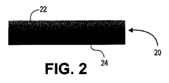
(000139) 図2及び3は、出発ホモポリマー内で組成勾配を生成させるためにどのように本発明を使用することができるかを示す。図2において、IPNが一方の側面22で形成され、濃度が減少して(例えば、実質的にホモポリマーのみ)別の側面24に伸長して、勾配が材料20中で厚さ方向に沿って形成されている。図3において、外側表面32が最高濃度のIPNとなり、中心又はコア34が最低濃度のIPNを有して、IPN濃度勾配が材料30内で放射状となっている。円筒又は球体の場合、IPNを形状のコアに配置し、疎水性ポリマーを形状の外面に配置して、逆の勾配を作ることもできる。これは、勾配組成を介して疎水性絶縁材料内にカプセル化された伝導性半IPNワイヤーを生成させるのに有用である。
[000139] FIGS. 2 and 3 show how the present invention can be used to generate compositional gradients within a starting homopolymer. In FIG. 2, an IPN is formed on one
(000140) 図4Aは、本発明に係る熱可塑性勾配IPNを製作する方法を示す。熱可塑性材料40の一方の側面は、光開始剤(図示せず)及び架橋剤(図示せず)とともにモノマー溶液42を吸収し、その後、モノマーは、熱可塑性物質内で(例えば、紫外線44によって)重合及び架橋させられて、勾配IPN46を形成する。pHを中性に増大させること47及び周囲の流体中に塩を導入すること48は、第2のポリマーネットワークのイオン化をもたらす。或いは、非イオン性モノマーを(コポリマーを形成するために)部分的に基礎として使用することができる。非イオン性ポリマーは、緩衝溶液によってイオン化されないが、それでもなお親水性表面を生成させる。いずれのタイプのモノマー系も水又は有機溶媒のいずれかと併用することができる。
[000140] FIG. 4A illustrates a method of making a thermoplastic gradient IPN according to the present invention. One side of the
(000141) 一実施形態において、ポリウレタン(「PU」)が一方の側面でのみAA中で膨潤する場合、又はTPのバルクからのモノマーの拡散が終了しないように膨潤時間が制限される場合、TP/PAA IPNを勾配中に生成させることができる。これは、整形外科用関節置換材料のための骨軟骨グラフトの生成において特に有用である。例えば、軟骨置換材料の場合、材料の一方の側面は潤滑性かつ水膨潤性になるが、他方は固体(純粋な熱可塑性物質)のままである。その間は、TP/PAAのIPNとTPとの間の移行部であり、PAA含有量は一方の表面から他方へと減少する。或いは、TP中へのAAの拡散がバルク中へのモノマーの浸透の時期を選ぶことによって正確に制御される場合、TP/PAAのIPN外面とPUのみの「コア」とを有するバルク材を作製することができる。この立体形状から生じる示差膨潤は、材料の機械的挙動及び疲労挙動の促進を助けることができる残留応力(膨潤面での圧縮、非膨潤面での引張)をもたらすことができる。厚さ勾配を有する材料の場合、熱可塑性物質のみの材料の土台は、装置を解剖学的な領域又は対象に錨着、接着、又は縫合するために使用することができる。この土台は、小さい領域に限定されるか、又は大きいものであることができ(例えば、スカート)、単一の成分又は複数の成分(例えば、ストラップ)として外側に向かって伸長することができる。処理中又は膨潤後に熱可塑性物質内で構築された内部応力は、温度誘発性アニーリングによって低下させることができる。例えば、60〜120℃の温度を、様々な時間(30分〜数時間)、ポリマーをアニーリングするために使用することができ、熱を、オーブン中で、熱面によるか、放射によるか、又はヒートガンによって適用することができる。熱可塑性物質は、例えば、ガンマ線又は電子ビーム放射線を用いて後で架橋することができる。 [000141] In one embodiment, when polyurethane ("PU") swells in AA only on one side, or when swelling time is limited so that monomer diffusion from the bulk of TP is not terminated. / PAA IPN can be generated during the gradient. This is particularly useful in the generation of osteochondral grafts for orthopedic joint replacement materials. For example, in the case of a cartilage replacement material, one side of the material becomes lubricious and water swellable while the other remains solid (pure thermoplastic). In the meantime, it is a transition between TP / PAA IPN and TP, and the PAA content decreases from one surface to the other. Alternatively, if the diffusion of AA into the TP is precisely controlled by choosing the timing of monomer penetration into the bulk, create a bulk material with the IPN outer surface of the TP / PAA and a PU-only “core” can do. The differential swelling resulting from this three-dimensional shape can result in residual stresses (compression on the swollen surface, tension on the non-swelled surface) that can help promote the mechanical and fatigue behavior of the material. In the case of materials with a thickness gradient, a thermoplastic-only material foundation can be used to attach, bond, or suture the device to an anatomical region or object. This foundation can be confined to a small area or can be large (eg, a skirt) and can extend outward as a single component or multiple components (eg, straps). The internal stress built up in the thermoplastic during processing or after swelling can be reduced by temperature-induced annealing. For example, a temperature of 60-120 ° C. can be used to anneal the polymer for various times (30 minutes to several hours), and heat can be applied in the oven, by a hot surface, by radiation, or Can be applied with a heat gun. The thermoplastic can be later crosslinked using, for example, gamma radiation or electron beam radiation.
(000142) 図4Bは、所望の組成を生成させるために勾配IPNの特性がどのように変化することができるかを示す。図4Cは、疎水性ポリマー及びイオン性ポリマーの濃度勾配が勾配IPNの(2つの表面の間の)厚さにわたってどのように変化することができるかを示す。組成勾配は、IPNが、一方の側面では水和されていて、かつより柔軟であり、他方ではあまり水和されておらず(又は全く水和されておらず)、かつ剛性である特性勾配を生じさせる。 [000142] FIG. 4B shows how the properties of the gradient IPN can be varied to produce the desired composition. FIG. 4C shows how the concentration gradient of hydrophobic polymer and ionic polymer can vary across the thickness (between the two surfaces) of the gradient IPN. The composition gradient is a characteristic gradient in which the IPN is hydrated and more flexible on one side, less hydrated (or not hydrated at all) and rigid on the other. Cause it to occur.
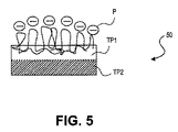
(000143) 図5に示すように、本発明のIPN及び半IPNから作製される物品は、積層構造で形成させることもできる。一実施例において、IPN構造50は、ポリカーボネートウレタンなどの第2の熱可塑性物質(TP2)の上に形成される、ポリエーテルウレタンなどの第1の熱可塑性物質(TP1)に相互透過しているポリ(アクリル酸)などの親水性ポリマー(P)から構成される。TP1とTP2は両方とも、それ自体、様々な硬さ及び特性の多数の層から構成されることができる。更に、3以上の多数の熱可塑性物質層を使用することができ、熱可塑性物質のうちの1つ又は複数を架橋することができる。最終的に、非熱可塑性要素をこの構築物中に組み込むことができる。
(000143) As shown in FIG. 5, an article made from the IPN and semi-IPN of the present invention can also be formed in a laminated structure. In one embodiment, the
(000144) 本発明の勾配又は均一IPN及び半IPNから形成される物品は、所望の通りに成形することができる。図6は、勾配IPN物品の成形を示す。この工程は、均一IPN又は半IPNを成形するために使用することもできる。 [000144] Articles formed from the gradient or uniform IPN and semi-IPN of the present invention can be molded as desired. FIG. 6 shows the forming of a gradient IPN article. This process can also be used to form a uniform IPN or semi-IPN.
(000145) 図6に示すように、熱61を用いて、勾配IPNの熱可塑性側面50においてポリマー中の物理的架橋(例えば、ポリウレタン中のハードセグメント)を再アニーリングし、屈曲(例えば、型又は鋳型の上での)及び冷却の後に様々な所望の湾曲を生じさせることができる。図6は、勾配IPNの熱可塑性側面での凸面62と凹面64の両方の湾曲を示す。当然、他の形状を所望の通りに形成させることができる。熱可塑性物質の使用は、例えば、射出成形、反応性射出成形、圧縮成形、又はその代わりに浸漬流延による、所望の形状への装置の成形を促進する。その後、成形された装置を、後続のネットワーク浸透及び重合工程に供して、新しいIPN材料を生じさせることができる。
(000145) As shown in FIG. 6,
(000146) 本発明に係るIPN及び半IPN物品の成形は、インサイチュで、例えば、ヒトの身体内で形成させることができる。例えば、図7A〜Bは、熱可塑性勾配IPN70が大腿骨頭72の湾曲を包み込むのを可能にするように、熱可塑性勾配IPN70を加熱すること71を示す。図7C〜Dは、熱可塑性勾配IPN73が股関節ソケット75の湾曲に適合するのを可能にするように、熱74を熱可塑性勾配IPN73に適用することを示す。
[000146] IPN and semi-IPN articles according to the present invention can be formed in situ, for example, in the human body. For example, FIGS. 7A-B illustrate
(000147) 本発明に従って作製された、成形された又は成形されていないIPN及び半IPN物品は、他の表面に付着させることができる。図8A〜Dは、熱可塑性勾配IPN物品80を結合界面83において表面82に付着させるために、溶媒、セメント、又はのりなどの結合剤81をどのように使用することができるかを示す。溶媒の添加によって、例えば、材料が局所的に溶解し、表面との接触及び溶媒の乾燥の後、熱可塑性物質が表面に接着する。この方法を用いて、限定されないが、船舶の船体表面を含む、様々な物体の本発明の「パネル」を生成させることができる。「コーティング」は、材料を容器の外形又は容器の一部に真空形成させることによって適用することができる。類似のアプローチを用いて、勾配IPNを関節内の骨表面に付着させることができる。
[000147] Molded or unmolded IPN and semi-IPN articles made in accordance with the present invention can be attached to other surfaces. FIGS. 8A-D illustrate how a
(000148) 例えば、本発明の方法によって形成される本発明の組成物は、種々の状況において使用することができる。1つの特定の使用は、骨軟骨グラフト中の人工軟骨としてのものである。本発明は、天然軟骨の分子構造、並びに更に、弾性係数、破壊強度、及び潤滑性表面を模倣する相互透過性ポリマーネットワークに基づく骨温存関節形成装置を提供する。天然軟骨のこれらの構造面及び機能面のうちの少なくともいくつかを模倣して、本発明の半IPN及びIPNは、新規の骨温存「バイオミメティックリサーフェシング」関節形成手順の基礎を形成する。軟骨のみを置換するように設計されるので、そのような装置は、潤滑性関節表面及び骨統合可能な骨界面を特色とする、1組の可撓性の埋込み可能な装置として製作される。 [000148] For example, the compositions of the present invention formed by the methods of the present invention can be used in a variety of contexts. One particular use is as an artificial cartilage in an osteochondral graft. The present invention provides a bone-preserving arthroplasty device based on the molecular structure of natural cartilage and, furthermore, an interpenetrating polymer network that mimics the elastic modulus, breaking strength, and lubricious surface. Mimicking at least some of these structural and functional aspects of natural cartilage, the semi-IPNs and IPNs of the present invention form the basis of a novel bone-sparing “biomimetic resurfacing” arthroplasty procedure. Designed to replace only cartilage, such a device is fabricated as a set of flexible implantable devices featuring a lubricious joint surface and an osteointegrable bone interface.
(000149) 原理上、装置は、身体内の任意の関節表面のために作製することができる。例えば、脛骨プラトーを覆う装置は、類似の骨調製及びポリマーサイジング工程を必要とする。股関節内の大腿骨頭を覆う装置については、キャップ形状の装置が大腿骨頭の外形に緊密に適合する。寛骨臼を裏打ちする装置については、半球状のカップ形状の装置が関節唇を越えて延伸し、ソケット中の所定の位置に嵌入し、嵌合面に大腿骨頭を提供することができる。このようにして、患者の股関節の両側を修復して、キャップ・オン・キャップ型の関節接合を生成させることができる。しかしながら、表面の一方のみが損傷している場合、一方の側面のみをキャッピングして、キャップ・オン・軟骨型の関節接合を生成させることができる。更に、本発明の材料を用いて、代替のベアリング表面としての役割を果たす別の関節置換又はリサーフェシング装置(通常、金属から構成される)の関節接合表面をキャッピング又は裏打ちすることができる。 [000149] In principle, the device can be made for any joint surface in the body. For example, a device that covers the tibial plateau requires a similar bone preparation and polymer sizing process. For devices that cover the femoral head in the hip joint, the cap-shaped device closely fits the femoral head contour. For devices that line the acetabulum, a hemispherical cup-shaped device can extend beyond the articular lip and fit into place in the socket to provide the femoral head on the mating surface. In this way, both sides of the patient's hip joint can be repaired to produce a cap-on-cap articulation. However, if only one of the surfaces is damaged, only one side can be capped to create a cap-on-cartilage articulation. In addition, the materials of the present invention can be used to capping or lining the articulating surface of another joint replacement or resurfacing device (typically composed of metal) that serves as an alternative bearing surface.
(000150) 本発明を肩関節(同じく、ボール・アンド・ソケット関節)に対して用いてキャップ形状の装置を生成させるために、股関節の工程と同様の工程を使用する。例えば、浅いカップは、関節窩の内面を裏打ちするように生成させることができる。更に、手、指、肘、足首、足、及び椎間板椎間の他の関節用の装置も、この「キャッピング」概念を用いて生成させることができる。遠位大腿骨における一実施形態において、遠位大腿骨装置体積は、前十字靭帯及び後十字靭帯を温存しながら、骨の外形に従う。 [000150] In order to use the present invention for shoulder joints (also ball and socket joints) to produce cap-shaped devices, a process similar to that for the hip joint is used. For example, a shallow cup can be created to line the inner surface of the glenoid. In addition, devices for the hands, fingers, elbows, ankles, feet, and other joints between the intervertebral discs can also be generated using this “capping” concept. In one embodiment in the distal femur, the distal femoral device volume follows the contour of the bone while preserving the anterior and posterior cruciate ligaments.
(000151) 本発明に従って形成される人工軟骨の一実施形態において、75Dのショア硬度で予備形成されたポリエーテルウレタン装置が射出成形される。この装置を、その後、55Dの乾燥ショア硬度に調合されたポリエーテルウレタン(例えば、ジメチルアセトアミド中の25%Elasthane(商標)55D)を含有するビタミンE含有溶液中で溶液流延する。その後、流延層を対流式オーブン中で乾燥させて、溶媒を除去することができる。その後、装置を、アクリル酸、光開始剤、及び架橋剤の溶液中に24時間浸漬させ、その後、ガラス性の型の上に置き、紫外線に曝露させることができる。その後、得られた装置をリン酸緩衝食塩水中に含浸させ、その中で洗浄することができる。この工程を用いて、関節形成用途のための凸面装置又は凹面装置のいずれかを生成させる。射出成形された予備形成物は、その側面の1つに、従来の整形外科用骨セメントで骨に固定することができるようにする複数の空間(空孔又は特徴)を有する。
[000151] In one embodiment of an artificial cartilage formed in accordance with the present invention, a preformed polyetherurethane device with 75D Shore hardness is injection molded. This apparatus is then solution cast in a vitamin E-containing solution containing polyether urethane (eg, 25
(000152) 装置の別の実施形態において、一方の側面に表面特徴を有して予備形成されたポリカーボネートウレタンを製作し、続いて、ポリエーテルウレタンの溶液中でその側面のうちの1つの浸漬流延を行ない、その後、上記の工程と同様の工程を行なった。更に別の実施形態において、ショア硬度55Dのポリエーテルウレタン予備形成物(例えば、Elasthane(商標)55D)を射出成形し、続いて、上記のようにモノマー溶液中で浸漬を行なう。第2のポリマーネットワークの硬化後、装置を、一方の側面において、ショア硬度75Dのポリカーボネートウレタンで浸漬流延する。これらの実施形態のいずれかにおいて、更なる表面特徴を、限定されないが、機械加工(旋盤及びエンドミル)、溶液流延、溶剤溶着、超音波溶着、又は熱溶着を含む、いくつかの手段によって装置の骨界面側に追加することができる。
[000152] In another embodiment of the apparatus, a preformed polycarbonate urethane having surface features on one side is fabricated, followed by immersion in one of the sides in a solution of polyether urethane. Then, the same process as the above process was performed. In yet another embodiment, a polyetherurethane preform with a Shore Hardness of 55D (eg,
(000153) 多孔性ポリカーボネートウレタンIPN及び半IPN構造を本発明に従って作製することができる。限定されないが、Bionate(登録商標)55D、Bionate(登録商標)65D、及びBionate(登録商標)75Dを含む、ポリカーボネートウレタンの粒子(サイズ範囲:250〜1500μm)は、熱(220〜250℃)、圧力(0.001〜100MPa)、及び/又は10〜30分間の溶媒を用いて、型中で焼結させることができる。構造は、50〜2000μmの最終的な空孔サイズ、15〜70%の多孔率、及び10MPaを超える圧縮強度を有する。最終的な構造は、医学的及び獣医学的用途のための組織内方成長/統合を促進する多孔率を有する。この構築物は、単独で、又は本発明に記載の潤滑性ポリマーのいずれかから作られた重層ベアリング表面とともに使用することができる。以下に記載するように、軟骨が損傷している場合には、この材料を身体の関節内の軟骨置換プラグとして使用することができた。
[000153] Porous polycarbonate urethane IPN and semi-IPN structures can be made according to the present invention. Polycarbonate urethane particles (size range: 250-1500 μm), including but not limited to
(000154) 例えば、本発明の方法に従って作製される本発明の組成物は、完全に又は部分的に合成された骨軟骨グラフトとして使用することができる。骨軟骨グラフトは、多孔性骨又は合成多孔性骨様構造に錨着させ得る潤滑性軟骨様合成ベアリング層からなる。ベアリング層は、2つの領域:潤滑性の表面層及び剛性の骨錨着層を有する。一実施形態において、ベアリング層の上部の潤滑性領域は、2つのポリマーから構成される相互透過性ポリマーネットワークからなる。第1のポリマーは、限定されないが、ポリエーテルウレタン、ポリカーボネートウレタン、シリコーンポリエーテルウレタン、及びシリコーンポリカーボネートウレタンを含む、高い機械的強度を有する疎水性熱可塑性物質、又は尿素結合が取り込まれているこれらの材料、又は尿素結合が取り込まれているこれらの材料(例えば、ポリウレタン尿素)であってもよい。第2のポリマーは、限定されないが、アクリル酸及び/又はスルホプロピルメタクリレートを含む、イオン化可能ビニルモノマーに由来する親水性ポリマーであってもよい。ベアリング層の下部領域(骨錨着層)は、超音波溶着振動、超音波エネルギー、レーザーエネルギー、熱、RFエネルギー、及び電気エネルギーで流動を引き起こすことができる剛性の再吸収不可能な熱可塑性物質であってもよい。骨錨着層は、ベアリング層を骨又は骨様多孔性構造に錨着させるために使用される。多孔性骨を使用する場合、それは、ヒト又は動物由来の海綿骨であることができる。合成された骨様材料を使用する場合、それは、多孔性リン酸カルシウム(及び/又は限定されないが、多孔性炭酸アパタイト、β−リン酸三カルシウム、もしくはヒドロキシアパタイトを含む他の材料)、又は限定されないが、ポリカーボネートウレタン、ポリエーテルウレタン、PLA、PLLA、PLAGA、及び/もしくはPEEKを含む上記のような多孔性の再吸収可能な又は再吸収不可能な熱可塑性物質からなることができる。ベアリング層を、骨錨着材料を融解させ、骨又は骨様構造の空孔又は空間内に流入させるエネルギーと組み合わせた加圧を介して多孔性骨又は骨様構造に錨着させ、その後、エネルギー源を除去すると、材料は再固化する。エネルギー源としては、振動、超音波エネルギー、レーザーエネルギー、熱、RFエネルギー、及び電気エネルギーを挙げることができるが、これらに限定されない。 [000154] For example, the compositions of the present invention made according to the methods of the present invention can be used as fully or partially synthesized osteochondral grafts. An osteochondral graft consists of a lubricious cartilage-like synthetic bearing layer that can be anchored to porous bone or a synthetic porous bone-like structure. The bearing layer has two regions: a lubricious surface layer and a rigid osteosynthesis layer. In one embodiment, the lubricious region on top of the bearing layer consists of a mutually permeable polymer network composed of two polymers. The first polymer may be a hydrophobic thermoplastic having high mechanical strength, including but not limited to polyether urethane, polycarbonate urethane, silicone polyether urethane, and silicone polycarbonate urethane, or those incorporating urea linkages. Or those materials incorporating urea linkages (eg, polyurethaneurea). The second polymer may be a hydrophilic polymer derived from an ionizable vinyl monomer, including but not limited to acrylic acid and / or sulfopropyl methacrylate. The lower area of the bearing layer (an osteoclastic layer) is a rigid, non-resorbable thermoplastic that can cause flow with ultrasonic welding vibration, ultrasonic energy, laser energy, heat, RF energy, and electrical energy It may be. The bone anchoring layer is used to anchor the bearing layer to the bone or bone-like porous structure. If porous bone is used, it can be cancellous bone from human or animal origin. When using a synthetic bone-like material, it may be porous calcium phosphate (and / or other materials including but not limited to porous carbonate apatite, β-tricalcium phosphate, or hydroxyapatite), or , Polycarbonate urethane, polyether urethane, PLA, PLLA, PLAGA, and / or PEEK, as described above, can be made of porous resorbable or non-resorbable thermoplastics. The bearing layer is fused to the porous bone or bone-like structure via pressurization combined with the energy that melts the bone-causing material and flows into the voids or spaces of the bone or bone-like structure, and then the energy When the source is removed, the material resolidifies. Energy sources can include, but are not limited to, vibration, ultrasonic energy, laser energy, heat, RF energy, and electrical energy.
(000155) 以下の図は、哺乳動物(動物又はヒト)の身体内の損傷を受けた関節を部分的に又は完全にリサーフェシングする装置としての本発明の様々な実施形態を示す。これらの装置は、圧入、ねじ(再吸収可能もしくは再吸収不可能のいずれかの、金属もしくはプラスチック)、縫合糸(再吸収可能もしくは再吸収不可能なもの)、のり、粘着剤、光硬化性粘着剤(例えば、ポリウレタン、もしくは樹脂ベースのもの)、又はセメント(例えば、ポリメチルメタクリレートもしくはリン酸カルシウムもしくは歯科用セメント)などの任意の数の手段を介して骨に固定することができる。 [000155] The following figures show various embodiments of the present invention as a device for partially or fully resurfacing a damaged joint in the body of a mammal (animal or human). These devices are press fit, screw (metal or plastic, either resorbable or non-resorbable), sutures (resorbable or non-resorbable), glue, adhesive, light curable It can be secured to the bone via any number of means such as adhesives (eg polyurethane or resin based) or cements (eg polymethyl methacrylate or calcium phosphate or dental cement).
(000156) 図9A〜Dは、本発明のIPN又は半IPNから形成された骨軟骨グラフトインプラントを股関節又は肩関節などの関節内で軟骨を置換又は強化するためにどのように使用することができるかを示す。図9Aに示すように、人工軟骨90は、キャップ部分91及び任意のカラー92を有するソックスとして形成される。人工器官90を、図9Bに示すように反転させ、上腕骨又は大腿骨の頭部94に滑り込ませ得る。図10A〜Bに示す代替の実施形態において、人工器官90は、靭帯96又は他の解剖学的構造を収容する開口部95を含むことができる。
[000156] FIGS. 9A-D show how an osteochondral graft implant formed from an IPN or semi-IPN of the present invention can be used to replace or strengthen cartilage within a joint such as a hip or shoulder joint. Indicate. As shown in FIG. 9A, the
(000157) インプラント及び他の物品は、本発明に係る種々の複雑な形状で作製することができる。図11A〜Eは、単独で、又は膝関節内で軟骨を置換もしくは強化するために必要な任意の組み合わせで使用し得る本発明のIPN又は半IPNから形成された骨軟骨グラフトを示す。図11Aは、複数の大腿顆(或いはただ1つの顆)に係合するように構成された骨軟骨グラフト110を示す。図11Bは、脛骨プラトー113の一方又は両方の面に係合するように構成された骨軟骨グラフト111及び112を示す。図11Cは、膝蓋骨114に係合するように構成され、膝蓋大腿溝115に係合するように構成された骨軟骨グラフト119と関節連結した骨軟骨グラフト118を示す。図11Dは、外側半月及び内側半月を係合するように構成された骨軟骨グラフト116及び117を示す。図11Eは、これらの人工器官のいくつかを膝関節内の所定の位置にどのようにしてアセンブルし得るかを示す。
[000157] Implants and other articles can be made in a variety of complex shapes according to the present invention. FIGS. 11A-E show osteochondral grafts formed from an IPN or semi-IPN of the present invention that can be used alone or in any combination needed to replace or strengthen cartilage within the knee joint. FIG. 11A shows an
(000158) 骨軟骨グラフトは、指、手、足首、肘、足、又は脊椎などの、他の関節内でも使用することができる。例えば、図12A〜Bは、本発明のIPN又は半IPNから形成され、指関節における使用のために成形された骨軟骨グラフト121及び122を示す。図13A〜Bは、肩関節唇又は股関節唇の置換又はリサーフェシングにおいて使用するための本発明のIPN又は半IPNから形成された人工関節唇131を示す。図14は、滑液包骨軟骨グラフト141、関節唇骨軟骨グラフト142、関節窩骨軟骨グラフト143、及び上腕頭骨軟骨グラフト144としての本発明のIPN又は半IPNの使用を示す。図15は、椎間板椎間のリサーフェシングのための人工器官151及び152としての本発明のIPN又は半IPNの使用を示す。
[000158] Osteochondral grafts can also be used in other joints such as fingers, hands, ankles, elbows, feet, or spine. For example, FIGS. 12A-B show
(000159) 本発明のIPN及び半IPNの組成物は、関節面の部分的リサーフェシングのための人工軟骨プラグとして形成させることができる。図16Aは、本発明の勾配IPN組成物から形成された人工軟骨プラグ160を示す。プラグ160は、物品の熱可塑性側に形成され、骨の穴又は開口部に挿入されるように構成されたステム部分161を有する。プラグの頭部162は、上記のように、潤滑性IPN又は半IPNであるように形成される。図16Bは、多孔性表面が頭部162の下側163及びステム161の土台164に形成されているバリエーションを示す。図16C〜Dの実施形態において、多孔性表面は、土台164の中心部分165にのみ形成される。全ての実施形態において、ステム161を骨の穴又は開口部に圧入させ、人工軟骨として働くように、潤滑性IPN表面を露出させることができる。
[000159] The IPN and semi-IPN compositions of the present invention can be formed as artificial cartilage plugs for partial resurfacing of the articular surface. FIG. 16A shows an
(000160) 図17は、ステム171に、骨へのプラグの固定のためのねじを形成する螺旋状のねじ山173が提供されている人工軟骨プラグ170の実施形態を示す。頭部172の上部表面は、上記のように、潤滑性IPN又は半IPNである。
[000160] FIG. 17 shows an embodiment of an
(000161) 図18は、固定のための骨の穴への圧入挿入用の3つのステム181を有する人工軟骨プラグ180の実施形態を示す。プラグ頭部182の上部表面は、上記のように、潤滑性IPN又は半IPNである。
[000161] FIG. 18 shows an embodiment of an
(000162) 図19は、露出した頭部部分192がステム191と実質的に同じ直径である人工軟骨プラグ190の実施形態を示す。ステム191は、固定のために骨の穴に圧入させることができる。プラグ頭部192の上部表面は、上記のように、潤滑性IPN又は半IPNである。
[000162] FIG. 19 shows an embodiment of an
(000163) 図20は、露出した頭部部分202がステム201よりも狭く、ステム201が土台203に向かって広くなる人工軟骨プラグ200の実施形態を示す。ステム201は、固定のために骨の穴に圧入させることができる。プラグ頭部202の上部表面は、上記のように、潤滑性IPN又は半IPNである。
(000163) FIG. 20 shows an embodiment of an
(000164) 図21は、ステム211が固定を助けるための円周状のねじ山を有する人工軟骨プラグ210の実施形態を示す。ステム211は、固定のために骨の穴に圧入させることができる。プラグ頭部212の上部表面は、上記のように、潤滑性IPN又は半IPNである。
[000164] FIG. 21 shows an embodiment of an
(000165) 図22は、ステム221に粗い多孔性表面を付加する図19の実施形態と同様の実施形態を示す。プラグ頭部222の上部表面は、上記のように、潤滑性IPN又は半IPNである。
[000165] FIG. 22 shows an embodiment similar to that of FIG. 19 that adds a rough porous surface to the
(000166) 図23は、ねじ又はステムなどの追加の固定なしで、骨を物理的に把持するように形成された骨軟骨グラフト230の実施形態を示す。この実施形態において、人工器官の潤滑性IPN又は半IPN部分は、装置の凹面231にある。装置の反対の凸面232は、人工器官230が付着させられる骨の形状に一致するように成形される。表面232は、骨の内方成長を促進するように多孔性である。この場合の多孔性材料は、本発明に記載のポロゲン法から製作することができ、このポロゲンは、塩化ナトリウム、リン酸三カルシウム、ヒドロキシアパタイト、糖、及びこれらの誘導体又は組合せである。或いは、多孔性は、熱又は溶媒を用いて、ポリマービーズ(例えば、ポリエーテルウレタン又はポリカーボネートウレタン)を一緒に焼結させることに由来することができる。
[000166] FIG. 23 shows an embodiment of an
(000167) 骨への固定のために、ねじ穴を骨軟骨グラフトに提供することができる。図24において、人工器官240に、ねじ242のための2つの穴241が提供されている。人工器官240の骨と接触する凹側244は、(上記のように)骨の内方成長を促進するように多孔性であり、骨の物理的把持に適した形状を有する。人工器官の外凸面243は、上記のように、潤滑性IPN又は半IPNである。
[000167] A screw hole can be provided in the osteochondral graft for fixation to the bone. In FIG. 24, the
(000168) 図25において、骨軟骨グラフト250に、ねじ253の頭部を収容するためのねじ穴251及びくぼみ252が提供されている。人工器官250の骨と接触する凹側254は、(上記のように)骨の内方成長を促進するように多孔性であり、骨の物理的把持に適した形状を有する。人工器官の外凸面255は、上記のように、潤滑性IPN又は半IPNである。
[000168] In FIG. 25, the
(000169) 図26は、骨の穴へ挿入のためのステム261を有する骨軟骨グラフト260の実施形態を示す。人工器官260の骨と接触する凹側262は、(上記のように)骨の内方成長を促進するように多孔性であり、骨の物理的把持に適した形状を有する。人工器官の外凸面263は、上記のように、潤滑性IPN又は半IPNである。
[000169] FIG. 26 shows an embodiment of an
(000170) 図27A〜Bは、両側が潤滑性のインプラントを作製するために使用される本発明の組成物の実施形態を示す。図27Aにおいて、インプラント270は、椎間板を置換するようにサイジングされ、構成される。インプラント270は、その上側及び下側に(例えば、上記のように形成された)潤滑性IPN表面又は半IPN表面271及び272を有する。図27Bは、楔形の横断面を有する膝スペーサー273を示す。人工椎間板270と同様に、スペーサー273も、その上側及び下側に潤滑性IPN表面又は半IPN表面274及び275を有する。
[000170] FIGS. 27A-B show an embodiment of the composition of the present invention used to make a bilaterally lubricious implant. In FIG. 27A,
(000171) 上記の骨軟骨グラフト及び他のインプラントの多くは、単一の骨表面に張り付けられる。図28及び29は、互いに対して移動する、例えば、関節内の、2つの骨又は他の解剖学的要素の表面に付着している整形外科領域のインプラントを示す。図28において、インプラント280は、骨の内方成長を促進するために(上記のように)多孔性となるように形成された上部骨接触領域及び下部骨接触領域281及び282を有する。インプラント280の内部は、流体で満たされた包283である。内部に面するベアリング表面284及び285は、(上記のように)潤滑性IPN表面又は半IPN表面である。インプラント280は、例えば、介在スペーサーとして並びに関節の滑液包及び軟骨の置換物として使用することができる。図29のインプラント290は、図28のインプラントと類似しているが、関節を規定する骨の対応する穴に挿入及び固定するための上部ステム及び下部ステム291及び292を付加している。
[000171] Many of the osteochondral grafts and other implants described above are attached to a single bone surface. FIGS. 28 and 29 show orthopedic implants that are moving relative to each other, eg, attached to the surface of two bones or other anatomical elements within a joint. In FIG. 28, the
(000172) 図30A〜Bは、本発明の骨軟骨グラフト及び他のインプラントの骨の中への経時的な統合を示す。図30Aにおいて、上記のように形成された骨軟骨グラフトインプラント300が骨301上に配置されている。インプラント300は、上記のように任意に多孔性である、潤滑性IPN又は半IPNの表面302と、熱硬化性又は熱可塑性の疎水性ポリマーのみから形成された骨界面表面303とを有する。表面302と表面303の間は、IPN又は半IPNと疎水性ポリマーと間の勾配又は移行域304である。時間経過とともに、骨組織は、図30Bに示すように、骨301から骨接触面303の中へと及び骨接触面303を通って成長する。
[000172] FIGS. 30A-B illustrate the integration of osteochondral grafts and other implants of the present invention into bone over time. In FIG. 30A, the
(000173) 図31A〜Cは、本発明に従って軟骨の関節表面を修復するための骨軟骨インプラントの3つの可能な立体形状を示す。図31Aにおいて、インプラント310は、上記のように、熱硬化性又は熱可塑性の疎水性ポリマーから形成された骨接触表面312に移行する潤滑性IPN又は半IPN表面311を有するキャップとして形成される。埋め込まれた場合、インプラント310は、骨313の外側表面を覆う。
[000173] FIGS. 31A-C show three possible three-dimensional shapes of osteochondral implants for repairing the articular surface of cartilage according to the present invention. In FIG. 31A, the
(000174) 図31B及び31Cは、インプラント314が、上記のように、熱硬化性又は熱可塑性の疎水性ポリマーから形成された骨接触表面316に移行する潤滑性IPN表面又は半IPN表面315を有するパッチ又はプラグとして(それぞれ)形成されている立体形状を示す。埋め込まれた場合、インプラント314は、骨313の準備された開口部317内で適合する。
[000174] FIGS. 31B and 31C show that the
(000175) 本発明は、非医学的用途を有する。例えば、図32は、船舶の船体をリサーフェシングするための本発明の潤滑性IPN又は半IPN組成物の使用を示す。(上記のような)熱可塑性勾配IPNのパネル320を船体322の表面に付着させて、抗力及びバイオフィルム形成を低下させている。或いは、IPN材料を、いくつかの実施形態において、液体として船体に塗装し、硬化又は固化させることができる。勾配IPNは、その表面で負に電荷しているか又は非荷電であることができ、1つ又は複数のタイプのモノマー種から作製することができる。様々なUV保護剤及び抗酸化剤又は他の添加剤をこれらの材料に組み込んで、その性能を改善することもできる。
[000175] The present invention has non-medical applications. For example, FIG. 32 illustrates the use of a lubricious IPN or semi-IPN composition of the present invention for resurfacing a ship's hull. A
(000176) 図33は、回転及び転移部品330の表面331並びに静止部品332の表面333などの、互いに対して移動する機械部品の相互接続表面を修飾するための(上記のような)潤滑性の熱可塑性又は熱硬化性IPNの使用を示す。図34は、パイプ342の内部表面340の流体抗力を低下させるための(上記のような)潤滑性の熱可塑性又は熱硬化性IPNの使用を示す。
[000176] FIG. 33 illustrates a lubricity (as described above) for modifying the interconnecting surfaces of mechanical parts that move relative to each other, such as the
(000177) 本発明の材料は、電気化学的伝導性を必要とする用途において有用性を有する。IPN及び半IPNの伝導性は、材料の水和マトリックスを通るイオンの流れに基づく。ポリエーテルウレタンの薄膜を、アクリル酸と水の混合物の4つの異なる組成物(水中の15、30、50、及び70%のアクリル酸)で膨潤させた。その後、各々の膨潤した膜をUV光中で硬化させて半IPNを形成させた。その後、膜をPBS中で中和した。材料の電気抵抗は、オーム計を用いて測定した。抵抗を測定するために、IPN膜をペーパータオルで軽く叩いて余分なPBSを除去し、オーム計プローブを60〜70mmの膜幅で膜にクリップで留めた。初期抵抗値及び定常状態抵抗値を記録した。更に、未修飾のポリエーテルウレタン膜及び液体のPBSの抵抗を測定した。PBSの抵抗は、プローブ間の近似距離を60mmにして、オーム計プローブをPBS浴に直接入れることによって測定した。抵抗測定を以下の表に示す。

(000178) 結果は、半IPNの抵抗が純粋なPBS流体のみよりも低い(しかし、それと同じ桁内である)ことを示している。オーム計の限度は、40,000オームであった。絶縁体(ポリウレタンを含む)についての典型的な値は、1014〜1016オームであり;従って、PEUのみの抵抗値は、使用されたメーターの範囲外であった。PEU/PAA半IPNの透過性は、Maroudasらによって、Permeability of articular cartilage.Nature,1968.219(5160):p.1260−1に記載されている装置と同様の装置を用いて測定した。透過性は、ダルシーの法則(Q=KAΔp/L)に従って計算され、式中、Qは流速[mm3/秒]、Aはプラグの断面積[mm2]、Δpは適用される圧力勾配[MPa](加圧液体)、Lはヒドロゲルの厚さである。70%のアクリル酸から調製されるPEU/PAA半IPNの透過性は、K=1.45×10-17m4/N*秒であることが分かった。天然の軟骨については、文献値は、1.5×10-16〜2×10-15m4/N*秒の範囲である。従って、PEU/PAAは、軟骨よりも10〜100倍透過性が低く、それにより、天然の軟骨と比べて、長期の圧縮荷重下での脱水の傾向が低くなる場合がある。IPNの透過性は、膨潤溶液中のAAの濃度を変化させることによって調整することができ;AA含有量が高いほど、透過性は高い。対照的に、未修飾のPEU材料だけでは、溶質に対して事実上透過性がなく;それは、若干の水分(約1%)を保持するが、実際には、それは、溶質透過性マトリックスとして作用しない。 [000178] The results show that the resistance of the semi-IPN is lower (but in the same order of magnitude) as pure PBS fluid alone. The limit of the ohmmeter was 40,000 ohms. Typical values for insulators (including polyurethane) were 10 14 to 10 16 ohms; therefore, the resistance value of PEU only was outside the range of meters used. The permeability of the PEU / PAA semi-IPN was determined by Maraudas et al., Permeability of artificial cartridge. Nature, 1968.219 (5160): p. It measured using the apparatus similar to the apparatus described in 1260-1. Permeability is calculated according to Darcy's law (Q = KAΔp / L), where Q is the flow rate [mm 3 / sec], A is the cross-sectional area of the plug [mm 2 ], Δp is the applied pressure gradient [ MPa] (pressurized liquid), L is the thickness of the hydrogel. The permeability of PEU / PAA semi-IPN prepared from 70% acrylic acid was found to be K = 1.45 × 10 −17 m 4 / N * sec. For natural cartilage, literature values range from 1.5 × 10 −16 to 2 × 10 −15 m 4 / N * seconds. Therefore, PEU / PAA is 10-100 times less permeable than cartilage, which may reduce the tendency of dehydration under long-term compression loads compared to natural cartilage. The permeability of IPN can be adjusted by changing the concentration of AA in the swelling solution; the higher the AA content, the higher the permeability. In contrast, unmodified PEU material alone is virtually non-permeable to solutes; it retains some moisture (about 1%), but in fact it acts as a solute permeable matrix do not do.
(000179) 上記の組成物、物品、及び方法に対する他のバリエーション及び修飾としては、以下のものが挙げられる。 [000179] Other variations and modifications to the above compositions, articles, and methods include the following.
(000180) 第1のポリマーは、市販されているか又はオーダーメイドであり、いくつかの方法(例えば、押出、射出成形、圧縮成形、反応射出成形(RIM)、又は溶液流延)によって作製されるポリマーであることができる。第1のポリマーは、架橋しないか、又は様々な手段によって架橋することができる。どちらのポリマーも、例えば、ガンマ線又は電子ビーム放射線によって架橋することができる。 [000180] The first polymer is either commercially available or made to order and is made by several methods (eg, extrusion, injection molding, compression molding, reaction injection molding (RIM), or solution casting). It can be a polymer. The first polymer is not crosslinked or can be crosslinked by various means. Both polymers can be crosslinked, for example, by gamma rays or electron beam radiation.
(000181) 全体が少なくとも2質量%のイオン化可能な化学基を含有する限り、任意の数又は組合せのエチレン性不飽和モノマー又はマクロモノマー(例えば、反応性二重結合を含有する)を、第2の又は後続のネットワークの基礎として使用することができる。これらは、ビニル基、アクリレート基、メタクリレート基、アリルエーテル基、又はアクリルアミド基を含有するものを含むが、これらに限定されない。任意の数のペンダント官能基を、限定されないが、カルボン酸、スルホン酸、アセテート、アルコール、エーテル、フェノール、芳香族基、又は炭素鎖を含む、これらのエチレン性不飽和基に共役させることができる。 [000181] Any number or combination of ethylenically unsaturated monomers or macromonomers (eg, containing reactive double bonds) can be used as long as they contain at least 2% by weight of ionizable chemical groups. It can be used as the basis for the next or subsequent network. These include, but are not limited to, those containing vinyl groups, acrylate groups, methacrylate groups, allyl ether groups, or acrylamide groups. Any number of pendant functional groups can be conjugated to these ethylenically unsaturated groups including, but not limited to, carboxylic acids, sulfonic acids, acetates, alcohols, ethers, phenols, aromatic groups, or carbon chains. .
(000182) ポリウレタン系ポリマーは、(限定されないが)以下のものであることができる:ポリエーテルウレタン、ポリカーボネートウレタン、ポリウレタン尿素、シリコーンポリエーテルウレタン、又はシリコーンポリカーボネートウレタン。他のハードセグメント、ソフトセグメント、及び鎖伸長剤を有する他のポリウレタンが可能である。 [000182] The polyurethane-based polymer can be (but is not limited to) the following: polyether urethane, polycarbonate urethane, polyurethane urea, silicone polyether urethane, or silicone polycarbonate urethane. Other polyurethanes with other hard segments, soft segments, and chain extenders are possible.
(000183) 他のポリマーは、シリコーン(ポリジメチルシロキサン)又はポリエチレンのホモポリマー又はコポリマーなどの、第1のネットワーク中で使用することができる。 [000183] Other polymers can be used in the first network, such as silicone (polydimethylsiloxane) or polyethylene homopolymers or copolymers.
(000184) ポリウレタン系ポリマーを第1のポリマーとして使用する場合、ポリウレタン系ポリマーの物理的架橋及び化学的橋架の程度は、物理的架橋のみ(熱可塑性物質)から広範な化学的橋架の間で変化させることができる。化学的橋架の場合、架橋可能なポリウレタンは、単独で、又は熱可塑性物質(架橋されていない)ポリウレタンとの混合物として使用することができる。 [000184] When a polyurethane-based polymer is used as the first polymer, the degree of physical crosslinking and chemical crosslinking of the polyurethane-based polymer varies between only physical crosslinking (thermoplastic) and a wide range of chemical crosslinking. Can be made. In the case of chemical crosslinking, the crosslinkable polyurethane can be used alone or as a mixture with thermoplastic (non-crosslinked) polyurethane.
(000185) 重合の条件(すなわち、周囲酸素、UV強度、UV波長、露光時間、温度)を変化させてもよい。 [000185] Polymerization conditions (ie, ambient oxygen, UV intensity, UV wavelength, exposure time, temperature) may be varied.
(000186) 組成勾配の配向及び峻度は、モノマー中での浸漬の時間及び/又は方法などの様々な手段、並びに外部静水陽圧又は外部静水陰圧の適用によって変化させることができる。 [000186] The orientation and steepness of the composition gradient can be changed by various means such as the time and / or method of immersion in the monomer and the application of external positive or negative hydrostatic pressure.
(000187) 熱可塑性物質は、発泡又は塩溶脱などの様々な技術によって多孔性にすることができる。モノマー(例えば、AA)による多孔性ポリマー(例えば、PU)の膨潤と、それに続く、AAの重合の後、多孔性IPNが形成される。 [000187] Thermoplastic materials can be made porous by various techniques such as foaming or salt leaching. After swelling of the porous polymer (eg, PU) with a monomer (eg, AA) and subsequent polymerization of AA, a porous IPN is formed.
(000188) 熱可塑性物質の更なる層を、表面に新しい熱可塑性物質を硬化又は乾燥させることによって、IPN側又は熱可塑性物質側のみのいずれかで、材料に付加することができる。層は、全て同じ材料であることができるか、又は異なる材料(例えば、ABS+ポリウレタン、ポリエーテルウレタン+ポリカーボネートウレタンなど)であることができる。 [000188] Additional layers of thermoplastic can be added to the material either on the IPN side or only on the thermoplastic side by curing or drying the new thermoplastic on the surface. The layers can all be the same material or can be different materials (eg, ABS + polyurethane, polyether urethane + polycarbonate urethane, etc.).
(000189) 限定されないが、ジメチルアセトアミド、テトラヒドロフラン、ジメチルホルムアミド、エタノール、メタノール、アセトン、水、ジクロロメタン、プロパノール、メタノール、又はこれらの組合せを含む、いくつかの異なる溶媒を、ポリウレタン、第2のネットワーク、又は両方の合成において使用することができる。 (000189) A number of different solvents including, but not limited to, dimethylacetamide, tetrahydrofuran, dimethylformamide, ethanol, methanol, acetone, water, dichloromethane, propanol, methanol, or combinations thereof, polyurethane, second network, Or it can be used in both syntheses.
(000190) 光開始剤(例えば、フェノン含有化合物及びIrgacure(登録商標)製品)、熱開始剤、又は化学開始剤などの任意の数の開始剤を使用することができる。熱開始剤の例としては、アゾ化合物、過酸化物(例えば、過酸化ベンゾイル)、過硫酸塩(例えば、過硫酸カリウムもしくは過硫酸アンモニウム)、これらの誘導体、又は組合せが挙げられるが、これらに限定されない。 [000190] Any number of initiators can be used, such as photoinitiators (eg, phenone-containing compounds and Irgacure® products), thermal initiators, or chemical initiators. Examples of thermal initiators include, but are not limited to, azo compounds, peroxides (eg, benzoyl peroxide), persulfates (eg, potassium persulfate or ammonium persulfate), derivatives or combinations thereof. Not.
(000191) 架橋の同一性及び密度(例えば、モノマーに対して0.0001モル%〜25モル%の架橋剤)、開始剤濃度(例えば、モノマーに対して0.0001モル%〜10モル%)、前駆体ポリマーの分子量、ポリマーの相対的質量パーセント、光の波長(UVから可視の範囲)、光の強度(0.01mW/cm2〜1W/cm2)、温度、pH、及び膨潤液のイオン強度、並びに水和のレベルの変化。 (000191) Crosslink identity and density (eg, 0.0001 mol% to 25 mol% crosslinker relative to monomer), initiator concentration (eg, 0.0001 mol% to 10 mol% relative to monomer) , Molecular weight of the precursor polymer, relative weight percent of the polymer, wavelength of light (UV to visible range), light intensity (0.01 mW / cm 2 to 1 W / cm 2 ), temperature, pH, and swelling liquid Changes in ionic strength, as well as the level of hydration.
(000192) 第2のネットワーク材料は、架橋薬剤の非存在下で合成することができる。 [000192] The second network material can be synthesized in the absence of a cross-linking agent.
(000193) これらの材料の水含有量は、2%〜99%の範囲であることができる。 [000193] The water content of these materials can range from 2% to 99%.
(000194) IPNの異なる成分を、ポリ(ビニルアルコール)、ポリ(エチレングリコール)−アクリレート、ポリ(2−ヒドロキシエチルアクリレート)、ポリ(2−ヒドロキシエチルメタクリレート)、ポリ(メタクリル酸)、ポリ(2−アクリルアミド−2−メチルプロパンスルホン酸)、他のビニル基含有スルホン酸、ポリ(アクリルアミド)、ポリ(N−イソプロピルアクリルアミド)、ポリ(ジメタクリルアミド)、及びこれらの組合せ又は誘導体などの、イオン化可能モノマーと組み合わせて組み込むことができる。例えば、アクリル酸及びビニルスルホン酸又は2−アクリルアミド−2−メチルプロパンスルホン酸のコポリマーを第2のネットワーク用に生成させて、ポリウレタンの第1のネットワーク及びポリ(アクリル酸−コ−アクリルアミド−メチル−プロパンスルホン酸)コポリマーの第2のネットワークを形成させることができる。それらが少なくとも2質量%のイオン化可能モノマーを含有し、第1のポリマーが入り込む(膨潤する)ことができる限り、任意のモノマー又はモノマーの組み合わせを好適な溶媒と併用することができる。 (000194) Different components of IPN are combined with poly (vinyl alcohol), poly (ethylene glycol) -acrylate, poly (2-hydroxyethyl acrylate), poly (2-hydroxyethyl methacrylate), poly (methacrylic acid), poly (2 -Acrylamido-2-methylpropanesulfonic acid), other vinyl group-containing sulfonic acids, poly (acrylamide), poly (N-isopropylacrylamide), poly (dimethacrylamide), and combinations or derivatives thereof, etc. It can be incorporated in combination with a monomer. For example, a copolymer of acrylic acid and vinyl sulfonic acid or 2-acrylamido-2-methylpropane sulfonic acid may be produced for the second network to produce a first network of polyurethane and poly (acrylic acid-co-acrylamide-methyl- A second network of (propanesulfonic acid) copolymers can be formed. Any monomer or combination of monomers can be used in combination with a suitable solvent so long as they contain at least 2% by weight of ionizable monomers and the first polymer can penetrate (swell).
(000195) IPNは、化学的にか又は物理的にかのいずれかで、そのバルク又はその表面に、抗酸化剤(例えば、ビタミンC、ビタミンE、Irganox(登録商標)、もしくはサントホワイト粉末)及び/又は抗微生物剤(例えば、抗生物質)などの特定の添加剤を組み込んでいることができる。これらは、例えば、メタクリレート、アクリレート、アクリルアミド、ビニル、又はアリルエーテルなどの任意のビニル基含有モノマーによる抗酸化剤のエステル化によって、材料に化学的に結合させることができる。 [000195] IPN is either chemically or physically, in its bulk or on its surface, an antioxidant (eg, vitamin C, vitamin E, Irganox®, or Santo White powder) And / or may incorporate certain additives such as antimicrobial agents (eg, antibiotics). These can be chemically coupled to the material, for example, by esterification of the antioxidant with any vinyl group-containing monomer such as methacrylate, acrylate, acrylamide, vinyl, or allyl ether.
(000196) その各々が架橋されているか又は架橋されていない、2を超えるネットワーク(例えば、3つ又はそれより多く)を形成させることもできる。 [000196] It is also possible to form more than two networks (eg, three or more), each of which is cross-linked or not cross-linked.
(000197) ポリウレタンそれ自体を、いくつかの方法で、例えば、水素化ナトリウムの存在下での1,3プロパンスルホンの反応によるウレタン基でのスルホン化によるか、又は過剰のイソシアネート基との反応によるウレタン基でのアロファネート結合の形成によって修飾することができる。例えば、過剰のイソシアナトエチルメタクリレートを、トルエン中のポリウレタンとジラウリン酸ジブチルスズの存在下で2.5時間反応させて、メタクリルオキシ共役ポリウレタン表面を生じさせることができる。その後、メタクリルオキシ基を用いて、フリーラジカル重合によって、他のメタクリルオキシ(又は他のビニル基)を含有するモノマー又はマクロモノマーを後から連結することができる。そのような修飾は、IPNの第2のネットワークの形成の前又は後に実行することができる。 [000197] Polyurethane itself is obtained in several ways, for example by sulfonation with urethane groups by reaction of 1,3 propanesulfone in the presence of sodium hydride or by reaction with excess isocyanate groups. It can be modified by the formation of allophanate bonds at the urethane group. For example, excess isocyanatoethyl methacrylate can be reacted for 2.5 hours in the presence of polyurethane in toluene and dibutyltin dilaurate to produce a methacryloxy conjugated polyurethane surface. Then, the monomer or macromonomer containing another methacryloxy (or other vinyl group) can be connected later by free radical polymerization using a methacryloxy group. Such modification can be performed before or after the formation of the second network of IPNs.
(000198)
実施例1
一実施例において、ポリカーボネートウレタン(Bionate55D)を、モノマーに対して0.1%v/vの2−ヒドロキシ−2−メチルプロピオフェノン及び0.1%v/vのトリエチレングリコールジメタクリレートを含有する水中の70%アクリル酸に一晩浸漬させた。ポリカーボネートウレタンを溶液から取り出し、2つのガラススライドの間に置き、UV光(2mW/cm2)に15分間曝露させた。得られた半IPNを取り出し、リン酸緩衝食塩水中で洗浄し、膨潤させた。材料は膨潤し、数時間以内に潤滑性になった。他の実施例において、セグメント化ポリウレタン尿素、並びにシリコーンポリエーテルウレタン及びシリコーンポリカーボネートウレタンをアクリル酸溶液中に入れ、同じ様式で重合させ、洗浄して、潤滑性IPNを得た。
(000198)
Example 1
In one example, polycarbonate urethane (
(000199)
実施例2
別の実施例において、ポリエーテルウレタン(Elasthane(商標)55D)を、モノマーに対して0.1%v/vの2−ヒドロキシ−2−メチルプロピオフェノン及び0.1%v/vのトリエチレングリコールジメタクリレートを含有する水中の70%アクリル酸に一晩浸漬させた。ポリエーテルウレタンを溶液から取り出し、2つのガラススライドの間に置き、その後、UV光(2mW/cm2)に15分間曝露させた。得られた半IPNを取り出し、その後、リン酸緩衝食塩水中で洗浄し、膨潤させた。材料は膨潤し、数時間以内に潤滑性になった。他の実施例において、ポリカーボネートウレタン、セグメント化ポリウレタン尿素、並びにシリコーンポリエーテルウレタン及びシリコーンポリカーボネートウレタンをアクリル酸溶液中に入れ、同じ様式で重合させ、洗浄して、潤滑性IPNを得た。
(000199)
Example 2
In another example, polyether urethane (
(000200)
実施例3
別の実施例において、シリコーンポリエーテルウレタン及びシリコーンポリカーボネートウレタンを、モノマーに対して0.1%v/の2−ヒドロキシ−2−メチルプロピオフェノン及び0.1%v/vのトリエチレングリコールジメタクリレートを添加した100%アクリル酸溶液中に別々に一晩入れた。重合及び架橋の後、半IPNは膨潤し、潤滑性になった。ポリウレタン中へのシリコーン(ポリジメチルシロキサン)の添加は、材料に対する追加のレベルの生体安定性、並びに潜在的に有用な表面の化学的性質及び特性を付加する。
(000200)
Example 3
In another embodiment, silicone polyether urethane and silicone polycarbonate urethane were added to the monomer at 0.1% v / 2-hydroxy-2-methylpropiophenone and 0.1% v / v triethylene glycol diene. Separately put overnight in 100% acrylic acid solution with methacrylate added. After polymerization and crosslinking, the semi-IPN swelled and became lubricious. The addition of silicone (polydimethylsiloxane) into the polyurethane adds an additional level of biostability to the material, as well as potentially useful surface chemistry and properties.
(000201)
実施例4
別の実施例において、メタクリルオキシ官能基化ポリカーボネートウレタンをUV光に曝露させて、ポリカーボネートウレタンを架橋し、その後、モノマーに対して0.1%v/vの2−ヒドロキシ−2−メチルプロピオフェノン及び0.1%v/vのトリエチレングリコールジメタクリレートを含有する70%アクリル酸中で一晩膨潤させた。材料を溶液から取り出し、2つのガラススライドの間に置き、その後、UV光(2mW/cm2)に15分間曝露させて、ポリカーボネートウレタン及びポリ(アクリル酸)の完全相互透過性ポリマーネットワークを得た。その後、IPNを水性塩溶液中で洗浄して、ポリ(アクリル酸)を中和し、平衡膨潤を達成し、未反応のモノマーを除去した。
(000201)
Example 4
In another example, methacryloxy-functionalized polycarbonate urethane is exposed to UV light to crosslink the polycarbonate urethane and then 0.1% v / v 2-hydroxy-2-methylpropio to monomer. Swelled overnight in 70% acrylic acid containing phenone and 0.1% v / v triethylene glycol dimethacrylate. The material was removed from the solution, placed between two glass slides, and then exposed to UV light ( 2 mW / cm 2 ) for 15 minutes to give a fully interpenetrating polymer network of polycarbonate urethane and poly (acrylic acid). . The IPN was then washed in an aqueous salt solution to neutralize the poly (acrylic acid), achieve equilibrium swelling, and remove unreacted monomer.
(000202)
実施例5
別の実施例において、メタクリルオキシ官能基化ポリエーテルウレタンをUV光に(0.1%の2−ヒドロキシ−2−メチルプロピオフェノン及び0.1%のトリエチレングリコールジメタクリレートの存在下で)曝露させて、ポリエーテルウレタンを架橋し、その後、前述の光開始剤及び架橋剤を含む70%のアクリル酸中で膨潤させ、その後、UV開始架橋を行なって、ポリエーテルウレタン及びポリ(アクリル酸)の完全相互透過性ポリマーネットワークを得た。その後、IPNを水性塩溶液中で洗浄して、ポリ(アクリル酸)を中和し、平衡膨潤を達成し、未反応のモノマーを除去した。
(000202)
Example 5
In another example, methacryloxy-functionalized polyether urethane is exposed to UV light (in the presence of 0.1% 2-hydroxy-2-methylpropiophenone and 0.1% triethylene glycol dimethacrylate). Exposed to cross-link the polyether urethane and then swell in 70% acrylic acid containing the photoinitiator and cross-linking agent described above, followed by UV-initiated cross-linking to make the polyether urethane and poly (acrylic acid) ) A completely interpenetrating polymer network. The IPN was then washed in an aqueous salt solution to neutralize the poly (acrylic acid), achieve equilibrium swelling, and remove unreacted monomer.
(000203)
実施例6
別の実施例において、メタクリルオキシ官能基化ポリカーボネートウレタンの25%DMAC溶液を0.1%の前述の光開始剤とともにUV光に曝露させて、ポリカーボネートウレタンを架橋した。加熱した(60℃)対流式オーブン中で溶媒を除去した後、更なるポリカーボネートウレタン層を架橋ポリカーボネートウレタンの一方の側面に流延して、積層構造を得、その後、架橋した側面のみを、0.1%の2−ヒドロキシ−2−メチルプロピオフェノン及び0.1%のトリエチレングリコールジメタクリレートを含む70%のアクリル酸中で膨潤させ、その後、UV開始架橋を行なって、ポリカーボネートウレタン及びポリ(アクリル酸)の完全相互透過性ポリマーネットワークを得た。その後、IPNを水性塩溶液中で洗浄して、ポリ(アクリル酸)を中和し、平衡膨潤を達成し、未反応のモノマーを除去した。
(000203)
Example 6
In another example, a 25% DMAC solution of methacryloxy-functionalized polycarbonate urethane was exposed to UV light with 0.1% of the aforementioned photoinitiator to crosslink the polycarbonate urethane. After removing the solvent in a heated (60 ° C.) convection oven, a further polycarbonate urethane layer was cast on one side of the crosslinked polycarbonate urethane to obtain a laminated structure, after which only the crosslinked side was .Swelling in 70% acrylic acid containing 1% 2-hydroxy-2-methylpropiophenone and 0.1% triethylene glycol dimethacrylate followed by UV-initiated crosslinking to produce polycarbonate urethane and poly A fully interpenetrating polymer network of (acrylic acid) was obtained. The IPN was then washed in an aqueous salt solution to neutralize the poly (acrylic acid), achieve equilibrium swelling, and remove unreacted monomer.
(000204)
実施例7
別の実施例において、メタクリルオキシ官能基化ポリカーボネートウレタンの25%DMAC溶液を0.1%の前述の光開始剤とともにUV光に曝露させて、ポリエーテルウレタンを架橋した。加熱した(60℃)対流式オーブン中で溶媒を除去した後、更なるポリエーテルウレタン層を架橋ポリカーボネートウレタンの一方の側面に流延して、積層構造を得、その後、架橋した側面のみを、0.1%の2−ヒドロキシ−2−メチルプロピオフェノン及び0.1%のトリエチレングリコールジメタクリレートを含む70%のアクリル酸中で膨潤させ、その後、UV開始架橋を行なって、ポリエーテルウレタン及びポリ(アクリル酸)の完全相互透過性ポリマーネットワークを得た。その後、IPNを水性塩溶液中で洗浄して、ポリ(アクリル酸)を中和し、平衡膨潤を達成し、未反応のモノマーを除去した。
(000204)
Example 7
In another example, a 25% DMAC solution of methacryloxy-functionalized polycarbonate urethane was exposed to UV light with 0.1% of the aforementioned photoinitiator to crosslink the polyether urethane. After removing the solvent in a heated (60 ° C.) convection oven, a further polyether urethane layer was cast on one side of the cross-linked polycarbonate urethane to obtain a laminated structure, after which only the cross-linked side was The polyether urethane was swollen in 70% acrylic acid containing 0.1% 2-hydroxy-2-methylpropiophenone and 0.1% triethylene glycol dimethacrylate, followed by UV-initiated crosslinking. And a fully interpermeable polymer network of poly (acrylic acid) was obtained. The IPN was then washed in an aqueous salt solution to neutralize the poly (acrylic acid), achieve equilibrium swelling, and remove unreacted monomer.
(000205)
実施例8
別の組の実施例において、メタクルオキシ(methacroxy)官能基化ポリエーテルウレタンの層を射出成形ポリエーテルウレタンの層に流延し、別途に、別の層を射出成形ポリカーボネートウレタンの層に流延した。各々をUV光に曝露させて、積層構造を得た。架橋した側面のみを、0.1%の2−ヒドロキシ−2−メチルプロピオフェノン及び0.1%のトリエチレングリコールジメタクリレートを含む70%のアクリル酸中で膨潤させ、その後、UV開始架橋を行なって、完全相互透過性ポリマーネットワークを得た。その後、IPNを水性塩溶液中で洗浄して、ポリ(アクリル酸)を中和し、平衡膨潤を達成し、未反応のモノマーを除去した。
(000205)
Example 8
In another set of examples, a layer of methacryloxy functionalized polyether urethane was cast onto a layer of injection molded polyether urethane, and another layer was cast onto a layer of injection molded polycarbonate urethane. . Each was exposed to UV light to obtain a laminated structure. Only the cross-linked side was swollen in 70% acrylic acid containing 0.1% 2-hydroxy-2-methylpropiophenone and 0.1% triethylene glycol dimethacrylate, after which UV-initiated crosslinking was performed. As a result, a completely interpermeable polymer network was obtained. The IPN was then washed in an aqueous salt solution to neutralize the poly (acrylic acid), achieve equilibrium swelling, and remove unreacted monomer.
(000206)
実施例9
一実施例において、アクリロニトリルブタジエンスチレン(ABS)を、モノマーに対して0.1%のv/v 2−ヒドロキシ−2−メチルプロピオフェノン及び0.1%のv/vトリエチレングリコールジメタクリレートを含む水中で100%のアクリル酸に15分間曝露させた。表面曝露は、モノマー溶液をABSの表面に30分間液滴流延することによって遂行した。その後、ABSを2つのガラススライドの間に置き、その後、UV光(2mW/cm2)に15分間曝露させた。得られたABS/PAA勾配IPNを取り出し、その後、リン酸緩衝食塩水中で洗浄し、膨潤させた。IPNを水性塩溶液中で洗浄して、ポリ(アクリル酸)を中和し、平衡膨潤を達成し、未反応のモノマーを除去した。材料は膨潤し、数時間以内に潤滑性になった。
(000206)
Example 9
In one example, acrylonitrile butadiene styrene (ABS) is 0.1% v / v 2-hydroxy-2-methylpropiophenone and 0.1% v / v triethylene glycol dimethacrylate, based on monomer. Exposure to 100% acrylic acid in the contained water for 15 minutes. Surface exposure was accomplished by drop casting the monomer solution on the surface of the ABS for 30 minutes. The ABS was then placed between two glass slides and then exposed to UV light ( 2 mW / cm 2 ) for 15 minutes. The resulting ABS / PAA gradient IPN was removed and then washed and swollen in phosphate buffered saline. The IPN was washed in an aqueous salt solution to neutralize the poly (acrylic acid), achieve equilibrium swelling, and remove unreacted monomer. The material swelled and became lubricious within a few hours.
(000207)
実施例10
熱可塑性勾配IPNを再成形するために、熱を加えた。ABS/PAA勾配IPNを熱線銃を用いて加熱し、その後、円筒状ポリプロピレンチューブに押し付けた。材料を室温に冷却した後に、アセトンをABS/PAAとポリプロピレンの間に射出した。手で圧力をかけ、試料を乾燥させた後、結果は、ポリプロピレンチューブに包み込まれ、それに結合した熱可塑性勾配IPNであった。
(000207)
Example 10
Heat was applied to reshape the thermoplastic gradient IPN. The ABS / PAA gradient IPN was heated using a heat gun and then pressed against a cylindrical polypropylene tube. After the material was cooled to room temperature, acetone was injected between ABS / PAA and polypropylene. After applying pressure by hand and drying the sample, the result was a thermoplastic gradient IPN encased in and bonded to a polypropylene tube.
(000208)
実施例11
別の実施例において、ABSとポリカーボネートウレタンの間にアセトンを射出し、手で圧力をかけることによって、熱可塑性勾配ABS/PAAのIPNをポリカーボネートウレタンに付着させて、ポリカルボウレタンに結合した熱可塑性勾配IPNを得た。
(000208)
Example 11
In another embodiment, a thermoplastic gradient ABS / PAA IPN is attached to the polycarbonate urethane by injecting acetone between the ABS and the polycarbonate urethane and applying pressure by hand, and the thermoplastic bonded to the polycarbourethane. A gradient IPN was obtained.
(000209)
実施例12
別の実施例において、熱線銃を用いてポリウレタン側面に熱を加え、材料の湾曲を手で反転させ、かつ水中でIPNを冷却することによって、湾曲したポリカーボネートウレタンIPNを再び真っ直ぐにした。
(000209)
Example 12
In another example, a curved polycarbonate urethane IPN was straightened again by applying heat to the polyurethane side using a heat gun, manually reversing the curvature of the material, and cooling the IPN in water.
(000210)
実施例13
別の実施例において、ポリエーテルウレタン溶液(例えば、ジメチルアセトアミド(「DMAC」)中20%)を積層構造でポリカーボネートウレタン上に流延し、加熱した(60℃)対流式オーブン中で乾燥させ、その後、ポリエーテルウレタン表面のみを、モノマーに対して0.1%v/vの2−ヒドロキシ−2−メチルプロピオフェノン及び0.1%v/vのトリエチレングリコールジメタクリレートを含有する水中の70%のアクリル酸に15分間曝露させた。表面曝露は、前述のモノマー溶液中に含浸させた布を敷いた上に積層材ポリエーテルウレタン側面を下して置くことによって遂行した。材料を布マットから取り出し、2つのガラススライドの間に置き、その後、UV光(2mW/cm2)に15分間曝露させた。得られた勾配半IPNを取り出し、リン酸緩衝食塩水中で洗浄し、膨潤させた。材料は膨潤し、数時間以内に潤滑性になった。他の実施例において、ポリエーテルウレタン、セグメント化ポリウレタン尿素、シリコーンポリエーテルウレタン、及びシリコーンポリカーボネートウレタンを同じ方法で扱って、潤滑性半IPNを得た。
(000210)
Example 13
In another example, a polyetherurethane solution (eg, 20% in dimethylacetamide (“DMAC”)) was cast in a laminated structure onto polycarbonate urethane and dried in a heated (60 ° C.) convection oven, Thereafter, only the polyetherurethane surface was immersed in water containing 0.1% v / v 2-hydroxy-2-methylpropiophenone and 0.1% v / v triethylene glycol dimethacrylate relative to the monomer. Exposure to 70% acrylic acid for 15 minutes. Surface exposure was accomplished by placing the laminated polyether urethane side down on a cloth impregnated in the monomer solution described above. The material was removed from the fabric mat and placed between two glass slides before being exposed to UV light ( 2 mW / cm 2 ) for 15 minutes. The resulting gradient semi-IPN was removed, washed in phosphate buffered saline and allowed to swell. The material swelled and became lubricious within a few hours. In other examples, polyether urethane, segmented polyurethane urea, silicone polyether urethane, and silicone polycarbonate urethane were handled in the same manner to obtain a lubricious semi-IPN.
(000211)
実施例14
別の実施例において、50質量%塩化ナトリウムを含有するポリカーボネートウレタン(DMAC中20%)の層を、予備作製したポリエーテルウレタンポリカーボネートウレタン上に溶液流延し、対流下で80℃で乾燥させた。塩を水中で洗い流して、積層ポリウレタン上に多孔性側面を得た。他の材料は、塩化ナトリウム濃度を10%〜80%の間で変化させて作製した。
(000211)
Example 14
In another example, a layer of polycarbonate urethane (20% in DMAC) containing 50% by weight sodium chloride was solution cast onto a pre-made polyether urethane polycarbonate urethane and dried at 80 ° C. under convection. . The salt was washed away in water to obtain a porous side on the laminated polyurethane. Other materials were made with varying sodium chloride concentrations between 10% and 80%.
(000212)
実施例15
別の実施例において、20%のリン酸三カルシウムを含有するポリカーボネートウレタン(DMAC中20%)の層を、予備作製されたポリエーテルウレタン−ポリカーボネートウレタン上に溶液流延し、対流下で80℃で乾燥させた。リン酸三カルシウムは、骨誘導剤としてポリウレタン内に包埋されたままにした。他の材料は、リン酸三カルシウム濃度を0.001%〜20%の間で変化させて作製した。
(000212)
Example 15
In another example, a layer of polycarbonate urethane (20% in DMAC) containing 20% tricalcium phosphate was solution cast onto a pre-made polyether urethane-polycarbonate urethane and 80 ° C. under convection. And dried. Tricalcium phosphate remained embedded in the polyurethane as an osteoinductive agent. Other materials were made with varying tricalcium phosphate concentrations between 0.001% and 20%.
(000213)
実施例16
別の実施例において、ポリウレタン尿素(例えば、ジメチルアセトアミド中20%)を積層構造でポリカーボネートウレタン上に流延し、その後、ポリウレタン尿素表面のみを、モノマーに対して0.1%v/vの2−ヒドロキシ−2−メチルプロピオフェノン及び0.1%v/vのトリエチレングリコールジメタクリレートを含有する水中の70%のアクリル酸中で15分間曝露させた。表面曝露は、前述のモノマー溶液中に含浸させた布を敷いた上に積層材ポリウレタン尿素側面を下にして置くことによって遂行した。ポリカーボネートウレタンを布マットから取り出し、2つのガラススライドの間に置き、その後、UV光(2mW/cm2)に15分間曝露させた。得られた勾配半IPNを取り出し、その後、リン酸緩衝食塩水中で洗浄し、膨潤させた。材料は膨潤し、数時間以内に潤滑性になった。材料をPBS中で洗浄して、ポリ(アクリル酸)を中和し、平衡膨潤を達成し、未反応モノマーを除去した。
(000213)
Example 16
In another example, polyurethaneurea (eg, 20% in dimethylacetamide) is cast on polycarbonate urethane in a laminate structure, after which only the polyurethaneurea surface is 0.1% v /
(000214)
実施例17
別の実施例において、溶液(ジメチルアセトアミド中25%)中の熱可塑性ポリエーテルウレタンと混合したメタクリルオキシ官能基化ポリエーテルウレタンをUV光に曝露させて、ポリカーボネートウレタンを架橋した。その後、更なるポリエーテルウレタンの層を架橋ポリエーテルウレタンの一方の側面に流延して、積層構造を得、その後、架橋した側面のみを、前述の光開始剤及び架橋剤を含む70%のアクリル酸中で膨潤させ、その後、UV開始架橋を行なって、ポリエーテルウレタン及びポリ(アクリル酸)の完全相互透過性ポリマーネットワークを得た。その後、IPNを水性塩溶液中で洗浄して、ポリ(アクリル酸)を中和し、平衡膨潤を達成し、未反応のモノマーを除去した。
(000214)
Example 17
In another example, a polycarbonate urethane was crosslinked by exposing the methacryloxy-functionalized polyether urethane mixed with a thermoplastic polyether urethane in solution (25% in dimethylacetamide) to UV light. Thereafter, a further layer of polyether urethane is cast on one side of the cross-linked polyether urethane to obtain a laminated structure, after which only the cross-linked side is 70% of the photoinitiator and cross-linking agent containing Swelling in acrylic acid followed by UV-initiated crosslinking yielded a fully interpenetrating polymer network of polyetherurethane and poly (acrylic acid). The IPN was then washed in an aqueous salt solution to neutralize the poly (acrylic acid), achieve equilibrium swelling, and remove unreacted monomer.
(000215)
実施例18
一実施例において、平坦なシートを、ジメチルアセトアミド(DMAC)中での熱可塑性ポリウレタンの溶液流延によって生成させた。ポリエーテルウレタン(Elasthane(商標))、ポリカーボネートウレタン(Bionate)、ポリエーテルウレタン尿素(Biospan)、シリコーンポリカーボネートウレタン(Carbosil)、及びシリコーンポリエーテルウレタン(Pursil)のポリウレタン溶液は、製造者により、約25%の固体濃度のジメチルアセトアミド(DMAC)中で合成された。
(000215)
Example 18
In one example, a flat sheet was produced by solution casting of a thermoplastic polyurethane in dimethylacetamide (DMAC). Polyurethane solutions of polyether urethane (Elasthane ™), polycarbonate urethane (Bionate), polyether urethane urea (Biospan), silicone polycarbonate urethane (Carbosil), and silicone polyether urethane (Pursil) are about 25% by the manufacturer. Synthesized in dimethylacetamide (DMAC) at a solids concentration of%.
(000216)
実施例19
球体形状は、ガラス球体及びシリコーン球体を(DMAC中の)ポリウレタン溶液中で浸漬コーティングすることによって成型された。ポリカーボネートウレタン(DMAC中20%)を球状のガラス型(49.5mmの外径)に浸漬コーティングし、別途に、シリコーン球体に浸漬コーティングした。溶媒は、対流式オーブン中で80℃で乾燥させることによって除去した。この工程をもう2回繰り返して、合計3つのコーティングを生成させた。その後、この球体をポリエーテルウレタン(DMAC中20%)中で浸漬コーティングし、その後、対流下で80℃で乾燥させた。この工程ももう2回繰り返した。得られたキャップ形状の積層ポリウレタンを型から取り出し、その外側を0.1%の2−ヒドロキシ−2−メチル−プロピオフェノン及び0.1%のトリエチレングリコールジメタクリレートを含む水中の70%のアクリル酸溶液に1.5時間浸漬させた。キャップを反転させ、球状のガラス型の上に戻し、UV光(2mW/cm2)に15分間曝露させた。次に、キャップを型から取り出し、リン酸緩衝食塩水中に入れた。結果は、1つの潤滑性表面と1つの純粋な熱可塑性表面を有する球形の勾配IPNであった。他の温度及び他の溶媒、並びに他の型材料及びポリマー成分を用いて、この工程を実行することもできる。
(000216)
Example 19
The sphere shape was molded by dip coating glass spheres and silicone spheres in a polyurethane solution (in DMAC). Polycarbonate urethane (20% in DMAC) was dip coated on a spherical glass mold (49.5 mm outer diameter) and separately dip coated on a silicone sphere. The solvent was removed by drying at 80 ° C. in a convection oven. This process was repeated two more times to produce a total of three coatings. The spheres were then dip coated in polyether urethane (20% in DMAC) and then dried at 80 ° C. under convection. This process was repeated twice more. The resulting cap-shaped laminated polyurethane is removed from the mold and the outside is 70% in water containing 0.1% 2-hydroxy-2-methyl-propiophenone and 0.1% triethylene glycol dimethacrylate. It was immersed in an acrylic acid solution for 1.5 hours. The cap was inverted and returned to the spherical glass mold and exposed to UV light ( 2 mW / cm 2 ) for 15 minutes. The cap was then removed from the mold and placed in phosphate buffered saline. The result was a spherical gradient IPN with one lubricious surface and one pure thermoplastic surface. This process can also be performed using other temperatures and other solvents, and other mold materials and polymer components.
(000217)
実施例20
別の実施例において、ポリエーテルウレタンを0.1%の2−ヒドロキシ−2−メチルプロピオフェノン及び0.1%のメチレンビスアクリルアミドを含む70%のアクリル酸中で膨潤させた。材料の一方の側面を軽く叩いて乾燥させ、その後、空気に曝露させ、UV光で処理した。その後、得られた勾配半IPNを水性塩溶液中で洗浄して、ポリ(アクリル酸)を中和し、平衡膨潤を達成し、未反応のモノマーを除去した。他の実験において、材料を硬化時に窒素又はアルゴンに曝露させた。
(000217)
Example 20
In another example, the polyetherurethane was swollen in 70% acrylic acid containing 0.1% 2-hydroxy-2-methylpropiophenone and 0.1% methylenebisacrylamide. One side of the material was tapped to dry, then exposed to air and treated with UV light. The resulting gradient semi-IPN was then washed in an aqueous salt solution to neutralize the poly (acrylic acid), achieve equilibrium swelling, and remove unreacted monomer. In other experiments, the material was exposed to nitrogen or argon during curing.
(000218)
実施例21
別の実施例において、ポリエーテルウレタン(Elasthane(商標)55D)を射出成形し、その後、0.1%v/vの2−ヒドロキシ−2−メチルプロピオフェノン及び0.1%w/wのメチレンビスアクリルアミドを含む70%のアクリル酸中で膨潤させ、その後、UV開始架橋を行なって、ポリエーテルウレタン及びポリ(アクリル酸)の完全相互透過性ポリマーネットワークを得た。その後、IPNを水性塩溶液中で洗浄して、ポリ(アクリル酸)を中和し、平衡膨潤を達成し、未反応のモノマーを除去した。
(000218)
Example 21
In another example, a polyetherurethane (
(000219)
実施例22
別の実施例において、ポリエーテルウレタン(Elasthane(商標)75D)を射出成形し、ポリエーテルウレタン溶液(25%DMAC中のElasthane(商標)55D)中で一方の側面に浸漬流延(溶液流延)させ、対流式オーブン中で乾燥させて、DMAC溶媒を除去した。乾燥させた材料を、0.1%v/vの2−ヒドロキシ−2−メチルプロピオフェノン及び0.1%w/wのメチレンビスアクリルアミドを含む70%のアクリル酸中で膨潤させ、その後、UV開始架橋を行なって、ポリエーテルウレタン及びポリ(アクリル酸)の完全相互透過性ポリマーネットワークを得た。その後、IPNを水性塩溶液中で洗浄して、ポリ(アクリル酸)を中和し、平衡膨潤を達成し、未反応のモノマーを除去した。
(000219)
Example 22
In another example, polyether urethane (Elasthane ™ 75D) is injection molded and dip cast (solution cast on one side) in a polyether urethane solution (
(000220)
実施例23
別の実施例において、ポリカーボネートウレタン(Bionate75D)を射出成形し、ポリエーテルウレタン溶液(25%DMAC中のElasthane(商標)55D)中で一方の側面に浸漬流延(溶液流延)させ、対流式オーブン中で乾燥させて、DMAC溶媒を除去した。乾燥させた材料を、0.1%v/vの2−ヒドロキシ−2−メチルプロピオフェノン及び0.1%w/wのメチレンビスアクリルアミドを含む70%のアクリル酸中で膨潤させ、その後、UV開始架橋を行なって、ポリエーテルウレタン及びポリ(アクリル酸)の完全相互透過性ポリマーネットワークを得た。その後、IPNを水性塩溶液中で洗浄して、ポリ(アクリル酸)を中和し、平衡膨潤を達成し、未反応のモノマーを除去した。
(000220)
Example 23
In another example, polycarbonate urethane (Bionate 75D) was injection molded and dip cast (solution cast) on one side in a polyether urethane solution (
(000221)
実施例24
別の実施例において、ポリエーテルウレタン(Elasthane(商標)75D)を射出成形し、その後、メタクリルオキシ官能基化ポリエーテルウレタン溶液(25%DMAC中のElasthane(商標)55D)中で前述の光開始剤とともに浸漬流延(溶液流延)し、その後、UV光に曝露させて、メタクリルオキシ官能基化ポリエーテルウレタンを架橋した。その後、材料を対流式オーブン中で乾燥させて、DMAC溶媒を除去した。その後、乾燥させた材料を0.1%v/vの2−ヒドロキシ−2−メチルプロピオフェノン及び0.1%w/wのメチレンビスアクリルアミドを含む70%のアクリル酸中で膨潤させ、その後、UV開始架橋を行なって、ポリエーテルウレタン及びポリ(アクリル酸)の完全相互透過性ポリマーネットワークを得た。その後、IPNを水性塩溶液中で洗浄して、ポリ(アクリル酸)を中和し、平衡膨潤を達成し、未反応のモノマーを除去した。
(000221)
Example 24
In another example, polyether urethane (Elasthane ™ 75D) was injection molded, followed by the aforementioned photoinitiation in a methacryloxy-functionalized polyether urethane solution (
(000222)
実施例25
別の実施例において、ポリカーボネートウレタン(Bionate75D)を射出成形し、その後、メタクリルオキシ官能基化ポリエーテルウレタン溶液(25%DMAC中でElasthane(商標)55D)中で浸漬流延(溶液流延)し、その後、UV光に曝露させて、メタクリルオキシ官能基化ポリエーテルウレタンを架橋した。その後、材料を対流式オーブン中で乾燥させて、DMAC溶媒を除去した。その後、乾燥させた材料を、0.1%v/vの2−ヒドロキシ−2−メチルプロピオフェノン及び0.1%v/vのトリエチレングリコールジメタクリレートを含む70%のアクリル酸中で膨潤させ、その後、UV開始架橋を行なって、ポリエーテルウレタン及びポリ(アクリル酸)の完全相互透過性ポリマーネットワークを得た。その後、IPNを水性塩溶液中で洗浄して、ポリ(アクリル酸)を中和し、平衡膨潤を達成し、未反応のモノマーを除去した。
(000222)
Example 25
In another example, polycarbonate urethane (Bionate 75D) is injection molded and then dip cast (solution cast) in a methacryloxy functionalized polyether urethane solution (
(000223)
実施例26
別の実施例において、ポリエーテルウレタン(Elasthane(商標)55D)溶液を流延し、その後、0.1%v/vの2−ヒドロキシ−2−メチルプロピオフェノン及び0.1%w/wのメチレンビスアクリルアミドを含む酢酸中の35%のスルホプロピルメタクリレート中で膨潤させ、その後、UV開始架橋を行なって、ポリエーテルウレタン及びポリ(アクリル酸)の完全相互透過性ポリマーネットワークを得た。その後、半IPNを水で洗浄して、酢酸を除去し、その後、塩水溶液中で洗浄して、ポリ(アクリル酸)を中和し、平衡膨潤を達成し、未反応のモノマーを除去した。
(000223)
Example 26
In another example, a polyetherurethane (
(000224)
実施例27
別の実施例において、ポリエーテルウレタン(Elasthane(商標)55D)溶液を流延し、その後、0.1%v/vの2−ヒドロキシ−2−メチルプロピオフェノン及び0.1%w/wのメチレンビスアクリルアミドを含む水中の35%のスルホプロピルメタクリレート及び35%のアクリル酸中で膨潤させ、その後、UV開始架橋を行なって、ポリエーテルウレタン及びポリ(アクリル酸)の完全相互透過性ポリマーネットワークを得た。その後、半IPNを水性塩溶液中で洗浄して、ポリ(アクリル酸)/ポリ(スルホプロピルメタクリレート)コポリマーを中和し、平衡膨潤を達成し、未反応のモノマーを除去した。
(000224)
Example 27
In another example, a polyetherurethane (
(000225)
実施例28
別の実施例において、長方形のPMMA(プレキシグラス)の試料を、0.1%v/vの2−ヒドロキシ−2−メチルプロピオフェノン及び0.1%w/wのメチレンビスアクリルアミドを含む水中の100%のアクリル酸中で短時間膨潤させ、その後、UV開始架橋を行なって、PMMA及びポリ(アクリル酸)の完全相互透過性ポリマーネットワークを得た。その後、IPNを水性塩溶液中で洗浄して、ポリ(アクリル酸)を中和し、平衡膨潤を達成し、未反応のモノマーを除去した。
(000225)
Example 28
In another example, a sample of rectangular PMMA (Plexiglas) is in water containing 0.1% v / v 2-hydroxy-2-methylpropiophenone and 0.1% w / w methylenebisacrylamide. Swell for a short time in 100% acrylic acid, followed by UV-initiated crosslinking to obtain a fully interpenetrating polymer network of PMMA and poly (acrylic acid). The IPN was then washed in an aqueous salt solution to neutralize the poly (acrylic acid), achieve equilibrium swelling, and remove unreacted monomer.
(000226)
実施例29
別の実施例において、長方形のポリジメチルスルホキシド(PDMS、Sylgard(登録商標)184)の試料を製造者の仕様書に従って調製し、その後、テトラヒドロフラン中の35%のアクリル酸溶液中で0.1%v/vの2−ヒドロキシ−2−メチルプロピオフェノン及び0.1%v/vのトリエチレングリコールジメタクリレートとともに短時間膨潤させ、その後、UV開始架橋を行なって、PDMS及びポリ(アクリル酸)の完全相互透過性ポリマーネットワークを得た。IPNを水性塩溶液中で洗浄して、ポリ(アクリル酸)を中和し、平衡膨潤を達成し、未反応のモノマーを除去した。
(000226)
Example 29
In another example, a sample of rectangular polydimethylsulfoxide (PDMS, Sylgard® 184) was prepared according to manufacturer's specifications, followed by 0.1% in a 35% acrylic acid solution in tetrahydrofuran. Swell for a short time with v / v 2-hydroxy-2-methylpropiophenone and 0.1% v / v triethylene glycol dimethacrylate, followed by UV-initiated crosslinking to produce PDMS and poly (acrylic acid) A fully interpenetrating polymer network was obtained. The IPN was washed in an aqueous salt solution to neutralize the poly (acrylic acid), achieve equilibrium swelling, and remove unreacted monomer.
(000227)
実施例30
図35は、水和した関節形成装置の横断面であり、この関節形成装置が、事実上、一方の側で天然の軟骨の構造、弾性係数、破壊強度、及び潤滑表面を模倣し、他方の側で骨梁の剛性、強度、及び多孔性を模倣する合成型の骨軟骨グラフトであることを示す。この装置は、剛性で、多孔性で、かつ骨様の固定表面へとスムーズに移行する、潤滑性で、軟骨様のポリマーを特色とする複合勾配材料からなる。勾配は、柔軟で滑りやすい軟骨が表面から深部へと厚さ方向に沿って次第により硬くかつより骨様になる、天然の関節に固有の組成勾配を模倣するように設計された。実際、この「バイオミメティック」勾配は、下層にある骨に対して生理的な応力分配を生じさせ、一方でまた、装置と骨の剛性をそれらの接触点で効果的に一致させることによって、骨界面での微細動作を最小限に抑えるはずである。好適な材料は、例えば、以下に記載されており、その開示は、参照により本明細書中に組み込まれる:米国特許出願第61/079,060号明細書(2008年7月8日出願);米国特許出願第61/095,273号明細書(2008年9月8日出願);及び米国特許出願第12/148,534(2008年4月17日出願)。
(000227)
Example 30
FIG. 35 is a cross-section of a hydrated arthroplasty device that effectively mimics the structure, elastic modulus, breaking strength, and lubricated surface of natural cartilage on one side, It shows a synthetic osteochondral graft that mimics the stiffness, strength, and porosity of the trabecular bone. This device consists of a composite gradient material featuring a lubricious, cartilage-like polymer that is rigid, porous and smoothly transitions to a bone-like fixation surface. The gradient was designed to mimic the composition gradient inherent in natural joints, where the soft and slippery cartilage becomes increasingly stiffer and more bone-like along the thickness direction from surface to depth. In fact, this “biomimetic” gradient creates a physiological stress distribution for the underlying bone, while also effectively matching the device and bone stiffness at their point of contact. Minimal movement at the interface should be minimized. Suitable materials are described, for example, below, the disclosure of which is incorporated herein by reference: US Patent Application No. 61 / 079,060 (filed July 8, 2008);
(000228)
実施例31
図36は、本発明の材料が非常に親水性であることを示す接触角解析を示す。一滴の水を表面に置く場合、その滴が取る形状は表面の組成によって決まる。親水性表面は、水を引き付けてより平坦な滴を生成させるが、疎水性表面は、水を弾いてより丸い滴を生成させる。表面の親水性の程度は、接触角と呼ばれる、表面と水滴との間で生成される角度を測定することによって推測される。通常、より親水性の表面は、水との約0〜45°の接触角を有するが、より疎水性の表面は、水との45°よりも大きい接触角を有する。
(000228)
Example 31
FIG. 36 shows a contact angle analysis showing that the material of the present invention is very hydrophilic. When a drop of water is placed on the surface, the shape it takes depends on the composition of the surface. Hydrophilic surfaces attract water and produce flatter drops, while hydrophobic surfaces repel water and produce more round drops. The degree of surface hydrophilicity is inferred by measuring the angle generated between the surface and the water droplets, called the contact angle. Typically, more hydrophilic surfaces have a contact angle of about 0-45 ° with water, while more hydrophobic surfaces have a contact angle greater than 45 ° with water.
(000229) 本発明によって作製された荷電ヒドロゲルIPNと水との間の接触角を決定した。簡潔に述べると、1枚のElasthane(商標)55D(ポリエーテルウレタン)を、開始剤及び架橋剤を含むアクリル酸中に含浸させ、半IPN(PEU/PAA半IPN)を形成させるために硬化させた。硬化後、荷電したPEU/PAA半IPNをリン酸緩衝食塩水中で水和させた。材料を溶液から取り出し、表面を短時間軽く叩いて、残りの液体を除去した。一滴の水を材料の表面に置き、ゴニオメーターを用いて接触角を読み取った。結果は、約8°の接触角を示した。比較のために、溶液流延したポリウレタン及び射出成形したポリウレタンの出発材料で得られた読取りは、それぞれ、約72°及び69°の接触角を有していた。この結果は、本発明に係るポリウレタン中へのポリ(アクリル酸)ネットワークの取込みが表面親水性を劇的に増大させることを示す。
[000229] The contact angle between the charged hydrogel IPN made according to the present invention and water was determined. Briefly, a piece of
(000230)
実施例32
荷電ヒドロゲルIPNとポリウレタンの構造の相違は、透過電子顕微鏡法(TEM)によって示される。TEMは、材料の高拡大画像を生成させる。TEMを、本発明のポリエーテルウレタン/ポリ(アクリル)酸の半IPN(PEU/PAA半IPN)の試料及び未修飾のポリエーテルウレタンの試料に対して行なった。簡潔に述べると、1枚のElasthane(商標)55D(ポリエーテルウレタン)を、開始剤及び架橋剤を含むアクリル酸中に含浸させ、硬化させた。それを標準的な手順によって四酸化オスミウムで染色して、TEM解析を行なった。図37Aは、PEUの34,000倍の拡大図を示し、一方、図37Bは、PEU/PAA半IPNを示す。非晶性(ソフト)ドメイン及び規則性(ハード)ドメインに対応する明るい領域及び暗い領域のサイズは、未修飾のPEUと比べて、PEU/PAA半IPNのTEM画像中で増加した。PEU試料と比較したPEU/PAA試料中でのより大きいドメインサイズに基づくと、PAAは、PEUソフトセグメント内に隔離されているようであり、相分離の程度は、未修飾のPEUと比較して、PEU/PAA試料中でより高い。
(000230)
Example 32
Differences in structure between charged hydrogel IPN and polyurethane are shown by transmission electron microscopy (TEM). TEM generates a highly magnified image of the material. TEM was performed on samples of the polyetherurethane / poly (acrylic) acid semi-IPN (PEU / PAA semi-IPN) and unmodified polyetherurethane samples of the present invention. Briefly, a sheet of
(000231)
実施例33
図38は、図37と同じPEU/PAA半IPN材料のTEMを12,400倍の倍率で示す。模式図は、ハードセグメントが相互透過性ポリマーネットワークのソフトセグメントからどのように相分離するのかを示す。
(000231)
Example 33
FIG. 38 shows a TEM of the same PEU / PAA semi-IPN material as FIG. 37 at a magnification of 12,400. The schematic shows how the hard segments phase separate from the soft segments of the interpermeable polymer network.
(000232)
実施例34
図39は、整形外科用インプラントの例示的な関節界面表面を含むPEU/PAAのIPNの静的機械特性を示す。材料の初期引張ヤング係数、破断時ひずみ、及び破断時応力を決定するために、単軸引張試験を実施した。イヌの骨の標本を、ASTM D638に従って、0.3%/秒のひずみ速度で試験した。関節界面材料の材料についての平均真応力−真ひずみ曲線を図40に示す。曲線の線形部分において、(真応力、真ひずみ曲線から得られる)弾性係数はE=15.3MPaであり、これは、天然の軟骨について報告されている引張特性に非常に近い。最終的な真応力は、εult=143%の真ひずみで、約σult=52MPaであることが分かった(軟骨は、約65%のひずみで破損することに留意する)。張力下のひずみ硬化は、80%以上の真ひずみについて観察された。ポアソン比(平衡)は、イヌの骨の頸領域の側方収縮を測定することによって推定され、v=0.32でひずみ範囲に沿って一定であることが分かった。従って、体積弾性率は、方程式K=E/3(1−2v)から算出され、18.3MPaであることが分かった。ASTM D695による非拘束圧縮プラグ試験から、PEU/PAA半IPNが優れた圧縮特性を有し、15.6MPaの圧縮剛性係数(真応力−ひずみに基づく、引張係数と同じ)、及び50MPaを上回る破損強度を有することが明らかにされる。
(000232)
Example 34
FIG. 39 shows the static mechanical properties of PEU / PAA IPN including an exemplary joint interface surface of an orthopedic implant. A uniaxial tensile test was performed to determine the initial tensile Young's modulus, strain at break, and stress at break of the material. Dog bone specimens were tested according to ASTM D638 at a strain rate of 0.3% / sec. The average true stress-true strain curve for the material of the joint interface material is shown in FIG. In the linear part of the curve, the elastic modulus (obtained from the true stress, true strain curve) is E = 15.3 MPa, which is very close to the tensile properties reported for natural cartilage. The final true stress was found to be about σ ult = 52 MPa with a true strain of ε ult = 143% (note that cartilage breaks at about 65% strain). Strain hardening under tension was observed for true strains greater than 80%. The Poisson's ratio (equilibrium) was estimated by measuring the lateral contraction of the neck region of the dog's bone and was found to be constant along the strain range at v = 0.32. Therefore, the bulk modulus was calculated from the equation K = E / 3 (1-2v) and found to be 18.3 MPa. From unconstrained compression plug tests according to ASTM D695, PEU / PAA semi-IPN has excellent compression properties, 15.6 MPa compression stiffness coefficient (same as tensile modulus based on true stress-strain), and failure above 50 MPa It is revealed that it has strength.
(000233)
実施例35
図40は、毎分40℃で加熱速度の示差走査熱量測定(DSC)によって評価したPEU及びPEU/PAA半IPN試料の熱曲線を示す。図41は、2つの異なる加熱速度でDSCによって評価したPEU及びPEU/PAA半IPN試料の熱転移を比較したものである。ガラス転移温度Tg、結晶化温度、及び融解温度Tmを含む、熱転移温度を決定した。そのTg未満では、ポリマーの熱容量はより低く、ポリマーはより硬いか又はよりガラス質である。Tgより上では、ポリマーの熱容量は増加し、ポリマーはより可撓性になる。いくつかのポリマーについては、この温度より上は、結晶化温度であり、分子のドメインの少なくとも一部は、より組織化され、本質的に結晶性になる。より高い温度では、結晶性部分が完全に融解する融解温度となる。この手順を、変調示差走査熱量計及び冷凍冷却システム(RCS90)とともにTA機器Q200 DSCシステムを用いて、ASTM D3418−03試験方法に従って行なった。簡潔に述べると、1枚のElasthane(商標)55D(ポリエーテルウレタン)を、開始剤及び架橋剤を含むアクリル酸中に含浸させ、その後、硬化させた。少量(2〜6mg)のPEU/PAA半IPN試料を第1のアルミニウム皿に入れた。蓋を皿の上部に置き、汎用圧着プレスで圧着して、試料を皿と蓋の間に挟んだ。熱を第1の皿に加え、別途に、参照皿に加えて、各々に対する電流フローを変化させ、2つの材料の温度を同じに保った。試験中の材料の熱流量を温度に対してグラフ化した。曲線の傾きは熱転移温度を示す(図40)。いくつかの試験を、異なる加熱速度(毎分10℃及び40℃)を用いて実施した。異なる加熱速度で試験を行なうことによって、図41に見られるように、異なる分解能が熱転移について得られる。Tgが材料の以前の熱履歴に左右され得るので、材料を2つの熱サイクルに供する。第1の熱サイクルは、ポリマーがその試験状態で達する条件を標準化するために使用され、第2の試験サイクルは、転移温度を生成させるために使用される。加熱速度を毎分10℃で保持したとき、PEU/PAA半IPNとPEUの両方についてのガラス転移温度Tgは、21℃付近であった。結晶化温度及び融解温度は、PEUと比較して、PEU/PAAでより低かった。毎分40℃の加熱速度では、結晶化温度は、PEUの93℃と比較して、PEU/PAAについて90℃であった。加熱速度を毎分10℃に下げたとき、観察される結晶化温度は、PEUの92℃と比較して、PEU/PAAについて79℃であった。最後に、毎分40℃の加熱速度では、Tm温度は、PEUの178℃と比較して、PEU/PAAについて164℃であった。加熱速度を毎分10℃に下げたとき、観察されるTm温度は、PEU/PAAについては154℃、PEUについては176℃及び186℃であった。PEUのいくつかの分析において、2つのTmが観察されたが(176℃及び186℃)、それは、ポリマー中に異なるセグメントがあることに起因する可能性がある。Tmの変化は、少なくとも一部は、PAAの追加によってポリマー体積の増加が生じ、ポリマーの体積当たりのハードセグメントがより少なくなることに起因する。
(000233)
Example 35
FIG. 40 shows the thermal curves of PEU and PEU / PAA semi-IPN samples evaluated by differential scanning calorimetry (DSC) of heating rate at 40 ° C. per minute. FIG. 41 compares the thermal transition of PEU and PEU / PAA semi-IPN samples evaluated by DSC at two different heating rates. The glass transition temperature T g, including crystallization temperature, and melting temperature Tm, and determine the thermal transition temperatures. Below its Tg, the heat capacity of the polymer is lower and the polymer is harder or more glassy. Above T g, the heat capacity of the polymer increases, the polymer becomes more flexible. For some polymers, above this temperature is the crystallization temperature, and at least some of the molecular domains become more organized and essentially crystalline. A higher temperature results in a melting temperature at which the crystalline portion is completely melted. This procedure was performed according to the ASTM D3418-03 test method using a TA instrument Q200 DSC system with a modulated differential scanning calorimeter and a refrigeration cooling system (RCS90). Briefly, a piece of
(000234)
実施例36
本発明のPEU/PAA半IPNのそれ自体に対する摩擦係数μを、ビルトイン型トルクセルを用いた摩耗試験においてリアルタイムで測定し、0.015〜0.06の範囲であることが分かったが、これは、図42に示すように、軟骨・オン・軟骨のμ値と類似している。(軟骨と比較した)そのより低い透過性のために、本発明のPEU/PAA半IPNは、より長い間、より高い接触圧力で、より低い摩擦係数を保持することができる。図42は、2.4MPaの連続的(静的)接触圧力下での関節界面材料(グラフ中で「PEU/PAA・オン・PEU/PAA」と表記されている)の摩耗試験における有効摩擦係数を示す。天然の軟骨の値に関する文献報告及びUHMWPE・オン・CoCrに関する実験データ/文献報告もプロットに提示されている(Mow,2005;Wright 1982)。予期した通り、摩擦係数は、荷重を1Hzのサイクルで適用したとき、時間経過とともに変化しないことが分かった;同様の結果が軟骨について報告されている。材料中の低い摩擦係数は、(a)ハイドロプレーニング作用、(b)材料の固体相と流体相の間での荷重の共有、(c)水が材料の表面に存続するときの薄膜の潤滑性の観点から説明することができる。静止荷重下でのμのわずかな増加は、圧力下での材料のわずかな部分脱水によって説明することができる。それに比べて、天然の軟骨は、静止荷重下でその水の大半を失い、従って、その摩擦係数は、速やかにかつより高いレベルまで増加する。荷重の除去及びその後の再水和は、天然の軟骨の初期の摩擦係数を回復させる。
(000234)
Example 36
The friction coefficient μ against the PEU / PAA semi-IPN itself of the present invention was measured in real time in a wear test using a built-in type torque cell and found to be in the range of 0.015 to 0.06. 42, it is similar to the μ value of cartilage / on / cartilage. Because of its lower permeability (compared to cartilage), the PEU / PAA semi-IPN of the present invention can retain a lower coefficient of friction at higher contact pressure for longer. FIG. 42 shows the effective friction coefficient in the wear test of the joint interface material (denoted as “PEU / PAA • on • PEU / PAA” in the graph) under a continuous (static) contact pressure of 2.4 MPa. Indicates. Literature reports on natural cartilage values and experimental / literature reports on UHMWPE on CoCr are also presented in the plot (Mow, 2005; Wright 1982). As expected, the coefficient of friction was found not to change over time when the load was applied at a 1 Hz cycle; similar results have been reported for cartilage. The low coefficient of friction in the material is: (a) hydroplaning action, (b) load sharing between the solid and fluid phases of the material, and (c) thin film lubricity when water remains on the surface of the material. It can be explained from the viewpoint. A slight increase in μ under static loading can be explained by a slight partial dehydration of the material under pressure. In comparison, natural cartilage loses most of its water under static loads, and therefore its coefficient of friction increases rapidly and to a higher level. Removal of the load and subsequent rehydration restores the initial coefficient of friction of natural cartilage.
(000235)
実施例37
摩擦係数は、物体の横移動に耐える力を示す数である。それは、摩擦力と垂直抗力との無単位比として表わされる。ポリエーテルウレタン/ポリアクリル酸(PEU/PAA)半IPNについての動摩擦係数を金属で試験した。この動摩擦係数を時間の関数として示す。簡潔に述べると、1片のElasthane(商標)55D(ポリエーテルウレタン)を、開始剤及び架橋剤を含むアクリル酸中に含浸させ、硬化させて、本発明の水膨潤性半IPNを形成させた。直径8.8mm及び厚さ1mmのプラグを切断し、PBS中で膨潤させ、その後、2.0MPaの接触応力で3/16インチのステンレス鋼ディスクに対して1Hzの周期で回転させながら、PBS中に沈めた。力荷重セルとトルク荷重セルの両方を装備した、ASTM F732標準に従って作製されたカスタムメイドの摩耗試験装置を用いて、動摩擦係数を摩耗試験実験においてリアルタイムで測定した。材料の動摩擦係数は、36時間にわたって0.005〜0.015の間で変化した。
(000235)
Example 37
The coefficient of friction is a number indicating the force withstanding the lateral movement of the object. It is expressed as a unitless ratio between friction force and normal force. The dynamic friction coefficient for polyetherurethane / polyacrylic acid (PEU / PAA) semi-IPN was tested with metals. This dynamic friction coefficient is shown as a function of time. Briefly, a piece of
(000236)
実施例38
本発明のPEU/PAA半IPNの摩耗実験を、ピン・オン・ディスク立体形状を用いて、ASTM F732に従って行なった。結果を図44、45、及び45に示す。関節界面材料から形成されたディスク及びピンを2,500,000サイクルまで試験した。業界基準材料との比較の根拠として、CoCrピン・オン・UHMWPE(超高分子量ポリエチレン上のコバルトクロム)ディスク立体形状も、1,000,000サイクルの間、試験した。
(000236)
Example 38
Wear experiments on the PEU / PAA semi-IPN of the present invention were conducted according to ASTM F732 using pin-on-disk solid geometry. The results are shown in FIGS. 44, 45 and 45. Disks and pins formed from joint interface materials were tested up to 2,500,000 cycles. As a basis for comparison with industry standard materials, CoCr pin-on-UHMWPE (cobalt chromium on ultra-high molecular weight polyethylene) disc geometry was also tested for 1,000,000 cycles.
(000237) 本発明のPEU/PAA半IPNの試験において、ピンは、直径8.8mm、厚さ2.5mmであった。ディスクは、直径88mm、厚さ2.5mmであった。ピンを、空気圧により適用される繰返し荷重下で、24mmの半径及び1.33Hzの速度で、ディスク上で回転させた。圧力調節器を用いて、所望の力が加えられるように大気圧を調整した。荷重は、荷重セル(Sensotec Honeywell,CA)を用いて、ディスク下で直接測定した。ディスク及びピンは、それらの間で発生した摩擦によって生じるトルクを、データ取得カード(National Instruments,TX)を装備したコンピュータに接続されたトルクセル(Transducer Techniques,CA)によって測定することができるよう、機械的に隔離された。ピン及びディスクは、PBSで満たされたチャンバーに収容された。温度は、熱電対−抵抗器−ファンシステムを用いて制御され、37℃で一定に保たれた。方程式μ=T/r*F(式中、Tは、測定されたトルク、rは、回転半径(=24mm)、Fは、ピンに加えられた力の合計である)を用いて、摩擦係数を持続的にモニタリングした。摩擦係数は、0.016で、接触圧力(試験範囲0.1〜3.5MPa)とは独立であり、かつ大きな静的接触荷重下で0.021へとわずかに増加したが、流体の回復後、もとの値に戻ることが分かった。100万サイクル毎に重量法を用いて、摩耗を測定し:ディスク及びピンは、3日間真空乾燥させた後、別々に秤量した。摩耗試験溶液(PBS)を回収して、目視検査し;目視可能な摩耗粒子の形跡は、試験のどの工程でも認められなかった。摩耗粒子を捕捉するために、摩耗試験PBS溶液を2.5μmのポアフィルターを用いて真空濾過し、脱イオン水で洗い流して、残存するPBSの塩を除去し、その後、真空及び乾燥剤下で一晩乾燥させた。対照として、同様の試験を、UHMWPE(Orthoplastics,UK)上のCoCrピン(Fort Wayne Metals,IN)を用いて実施した。OD=7mmの3つの研磨した(Ra<1.6μm)CoCrフラットピンを、3.4MPaの静的接触荷重下でかつ37℃の隔離された環境で1.2Hzで回転させて、厚さ2.5mm及びOD=88mm(回転半径=24mm)の研磨したUHMWPEディスクに対して、同じ機器で試験した。 [000237] In testing of the PEU / PAA semi-IPN of the present invention, the pin was 8.8 mm in diameter and 2.5 mm in thickness. The disc had a diameter of 88 mm and a thickness of 2.5 mm. The pin was rotated on the disc with a radius of 24 mm and a speed of 1.33 Hz under cyclic loading applied by air pressure. The atmospheric pressure was adjusted using a pressure regulator so that the desired force was applied. The load was measured directly under the disc using a load cell (Sensotec Honeywell, CA). The disks and pins are mechanical so that the torque caused by the friction generated between them can be measured by a torque cell (Transducer Techniques, CA) connected to a computer equipped with a data acquisition card (National Instruments, TX). Isolated. Pins and discs were housed in a chamber filled with PBS. The temperature was controlled using a thermocouple-resistor-fan system and was kept constant at 37 ° C. Using the equation μ = T / r * F, where T is the measured torque, r is the radius of rotation (= 24 mm), and F is the total force applied to the pin. Was continuously monitored. The coefficient of friction was 0.016, independent of contact pressure (test range 0.1-3.5 MPa) and increased slightly to 0.021 under large static contact loads, but fluid recovery Later, it turned out to return to the original value. Wear was measured using a gravimetric method every million cycles: discs and pins were vacuum dried for 3 days and then weighed separately. The abrasion test solution (PBS) was collected and visually inspected; no visible evidence of abrasion particles was observed at any stage of the test. To trap the wear particles, the wear test PBS solution is vacuum filtered using a 2.5 μm pore filter, rinsed with deionized water to remove residual PBS salts, and then under vacuum and desiccant. Dried overnight. As a control, a similar test was performed using CoCr pins (Fort Wayne Metals, IN) on UHMWPE (Orthoplastics, UK). Three polished (Ra <1.6 μm) CoCr flat pins with OD = 7 mm were rotated at 1.2 Hz in an isolated environment at 37 ° C. under a static contact load of 3.4 MPa and a thickness of 2 A polished UHMWPE disk of 0.5 mm and OD = 88 mm (turning radius = 24 mm) was tested on the same instrument.
(000238) 試験後に本発明のPEU/PAA半IPNから形成されたディスクの観察(図44A)から、ピン・オン・ディスク関節連結表面に沿った肉眼で認知可能な摩耗トラックは示されなかった。(図44Bは、摩耗トラックの位置の近接図である。破線は、経路を示すために追加されており;放射状の矢印はディスクの中心から始まる。)それと比べて、図44Cに示すように、CoCrピンに対する2.0Mサイクルの摩耗後のUHMWPEディスクは、126μmの深さの目視可能なトラックを有する。 [000238] Observation of a disk formed from the PEU / PAA semi-IPN of the present invention after the test (Figure 44A) showed no visible perceptible wear track along the pin-on-disk articulating surface. (FIG. 44B is a close-up view of the location of the wear track. Dashed lines have been added to show the path; radial arrows start from the center of the disk.) In comparison, as shown in FIG. 44C, The UHMWPE disc after 2.0M cycle wear on CoCr pins has a visible track of 126 μm depth.
(000239) 0.01mgの分解能を有する秤(Mettler Toledo,OH)を用いた摩耗試験溶液濾過液の秤量により、PEU/PAA半IPNの体積摩耗速度が約0.6mg/106サイクル又は0.63mm3/106サイクル又は0.63mm3/150×103mであることが示された。しかしながら、この値は、本方法の分解能に近い。PEU/PAA半IPNから構成される本発明の関節界面材料の摩耗試験からの摩耗試験溶液の模式図が図45Aに示されており、この図は、PBS溶液中に粒子が存在しないことを示している。図45Aと、CoCr・オン・UHMWPE摩耗試験時に生成された実質的な摩耗破片を示す図45B及び45Cに示されるUHMWPEディスクの摩耗試験溶液の模式図とを比較されたい。 (000239) The volume of the PEU / PAA semi-IPN volume wear rate is about 0.6 mg / 10 6 cycles or 0. 6 by weighing the wear test solution filtrate using a scale with a resolution of 0.01 mg (Mettler Toledo, OH). it has been shown 63mm is 3/10 6 cycles or 0.63 mm 3 / 0.99 × 10 3 m. However, this value is close to the resolution of the method. A schematic diagram of the wear test solution from the wear test of the joint interface material of the present invention composed of PEU / PAA semi-IPN is shown in FIG. 45A, which shows the absence of particles in the PBS solution. ing. Compare FIG. 45A with the schematic diagram of the UHMWPE disk wear test solution shown in FIGS. 45B and 45C showing substantial wear debris generated during the CoCr-on-UHMWPE wear test.
(000240) 結果の精度を高めるために、ほこり、水分、及び静電気などの外部要因を排除することに注意が払われたが、摩耗値は、利用可能な方法の統計的検出限界及び実際の検出限界に十分に近い。これらの結果は、本発明に係るPEU/PAA半IPNが−天然の軟骨と同じく−主に水から構成され、その表面が水の膜で持続的に潤滑化されるので、固体マトリックス間の接触は、あるとしても、ほとんどないという仮説と一致する。 [000240] In order to increase the accuracy of the results, care was taken to eliminate external factors such as dust, moisture, and static electricity, but the wear value is a statistical detection limit and actual detection of available methods. Close enough to the limit. These results show that the PEU / PAA semi-IPN according to the present invention—similar to natural cartilage—consists mainly of water and its surface is continuously lubricated with a film of water, so contact between solid matrices Is consistent with the hypothesis that there is little, if any.
(000241) 摩耗粒子測定をCoCr・オン・UHMWPE実験についても行ない、この実験により、UHMWPEディスク上に目視可能な摩耗トラック(図44B)が生成されただけでなく、実質的な肉眼的摩耗破片(図45B及びC)も生成された。UHMWPEディスクを秤量し、質量差から64mg/106サイクル又は69mm3/150×103mの平均摩耗速度が得られた(図46)。この研究は、本発明の関節界面材料(「PEU/PAA・オン・PEU/PAA」と表記されている)は、関節全置換術で広く使用されるCoCr−UHMWPEの従来の組み合わせよりも摩耗に対して少なくともあと100倍以上耐性があることを示している。 (000241) Wear particle measurements were also made for the CoCr-on-UHMWPE experiment, which not only generated a visible wear track on the UHMWPE disc (FIG. 44B), but also produced substantial gross wear debris ( 45B and C) were also generated. The UHMWPE disks were weighed and the average wear rate of 64 mg / 10 6 cycles or 69mm 3/150 × 10 3 m was obtained from the mass difference (Figure 46). This study shows that the joint interface material of the present invention (designated “PEU / PAA on PEU / PAA”) is more wearable than the conventional combination of CoCr-UHMWPE widely used in total joint replacement. It shows that it is at least 100 times more resistant.
(000242)
実施例39
図47は、様々な水性溶媒及び有機溶媒中のPEU/PAA及びPEUの膨潤挙動を示す。簡潔に述べると、1枚のElasthane(商標)55D(ポリエーテルウレタン)を開始剤及び架橋剤を有するアクリル酸中に含浸させ、硬化させて、半IPNを形成させた。IPN又はElasthane(商標)55Dの小片を得て、秤量した。試料を、図に示す溶媒を含む溶液中に20時間含浸させた。(試料は膨潤したが、溶解しなかった)。試料を溶媒から取り出し、短時間軽く叩いて乾燥させ、その後、再び秤量した。膨潤に起因する質量の変化を%差として表す。Elasthane(商標)55Dは単独で水を取り込まないが、本発明のIPNは水で容易に膨張して、潤滑性の水和したIPNを形成する。更に、他の溶媒を用いて、出発ポリマーを膨潤させ、本発明のIPNを生成させることができる。ポリウレタンの場合、様々な溶媒が材料を膨潤させる能力は、溶媒の特性(例えば、その極性、酸性度、及び分子量)、並びに溶媒中のポリマー成分(例えば、ハードセグメント及びソフトセグメント)の相対的溶解度に左右される。
(000242)
Example 39
FIG. 47 shows the swelling behavior of PEU / PAA and PEU in various aqueous and organic solvents. Briefly, a piece of
(000243)
実施例40
水及び酢酸中のアクリル酸によるポリエーテルウレタンの膨潤を試験した。脱イオン水(図48A)中及び酢酸(図48B)中に10、30、50、及び70%のアクリル酸モノマーを含む膨潤溶液を調製した。Elasthane(商標)(登録商標)55D(ポリエーテルウレタン)の小片を得、測定した。Elasthane(商標)の試料を各溶液中に入れた。試料を溶媒から取り出し、表面を短時間軽く叩いて乾燥させ、その後、再び測定した。膨潤に起因する変化を、平衡膨潤後の標本の最終的な長さ(Lf)をもとの長さ(Lo)で除したものから1を引いたものとして表わし;このようにして、初期状態(y=0)と比べた長さのわずかな増加を時間に対してプロットする。Elasthane(商標)55Dの膨潤を、水又は酢酸のいずれかを溶媒として用いて観察した。より多くの量のアクリル酸を膨潤溶液中で使用したときに、より多くの膨潤が観察された。Elasthane(商標)試料の膨潤に対するアクリル酸の濃度依存性は、水を溶媒として使用するか、又は酢酸を溶媒として使用するかによって異なることに留意する。
(000243)
Example 40
The swelling of polyether urethane by acrylic acid in water and acetic acid was tested. Swelling solutions were prepared containing 10, 30, 50, and 70% acrylic acid monomer in deionized water (FIG. 48A) and acetic acid (FIG. 48B). Small pieces of Elastane ™ (registered trademark) 55D (polyether urethane) were obtained and measured. A sample of Elastane ™ was placed in each solution. The sample was removed from the solvent, the surface was briefly tapped to dry, and then measured again. The change due to swelling is expressed as the final length (L f ) of the specimen after equilibrium swelling divided by the original length (L o ) minus 1; A slight increase in length compared to the initial state (y = 0) is plotted against time. The swelling of
(000244)
実施例41
図49は、硬化後のPEU/PAA半IPN中に存在するポリ(アクリル酸)の量が、様々な膨潤溶液中のアクリル酸モノマーの出発濃度の関数としてプロットされることを示す。
(000244)
Example 41
FIG. 49 shows that the amount of poly (acrylic acid) present in the PEU / PAA semi-IPN after curing is plotted as a function of the starting concentration of acrylic acid monomer in various swelling solutions.
(000245) 脱イオン水中及び酢酸中に10、30、50、及び70%のアクリル酸モノマーを含む膨潤溶液を調製した。Elasthane(商標)55D(ポリエーテルウレタン)の小片を得、秤量した。試料を、架橋剤及び開始剤とともに、各々の水/アクリル酸溶液又は酢酸/アクリル酸溶液中に入れた。試料を硬化させ、水又は酢酸のいずれか中のアクリル酸中で膨潤させ、溶液から取り出し、乾燥させ、その後、再び秤量した。半IPNを形成するElasthane(商標)55D中へのアクリル酸の取込みは、水又は酢酸のいずれかを溶媒として用いて観察された。より高濃度のアクリル酸が膨潤溶液中に存在するときに、より多くのアクリル酸の取込みが観察された。
[000245] Swelling solutions were prepared containing 10, 30, 50, and 70% acrylic acid monomer in deionized water and acetic acid. Small pieces of
(000246)
実施例42
半IPNを本質的には図49に記載されているように調製し、IPNのポリアクリル酸含有量を決定した。乾燥した材料を秤量し、平衡に達するまで食塩水中で膨潤させ、再び秤量した。半IPNの質量の変化は、ポリアクリル酸の各々の濃度について、膨潤した材料の質量/乾燥材料の質量の比(Ws/Wd)として表わされる。ポリマー中のポリアクリル酸の量の増加は、水膨潤性半IPN中への食塩水の取込みの増加と相関する。これらの実験における半IPNをpH7.4に中和した後、これらの実験において、半IPNの乾燥質量は、食塩水膨潤溶液中に存在する塩を含んでいたが、それは、一価陽イオン(主に23g/モルのMWを有するナトリウム)が、材料中のカルボキシレート基に対する対イオンであるためである。
(000246)
Example 42
A semi-IPN was prepared essentially as described in FIG. 49 and the polyacrylic acid content of the IPN was determined. The dried material was weighed, swollen in saline until equilibrium was reached, and weighed again. The change in the mass of the semi-IPN is expressed as the ratio of the mass of swollen material / the mass of dry material (Ws / Wd) for each concentration of polyacrylic acid. An increase in the amount of polyacrylic acid in the polymer correlates with an increase in saline uptake into the water-swellable semi-IPN. After neutralizing the semi-IPN in these experiments to pH 7.4, in these experiments, the dry mass of the semi-IPN contained the salt present in the saline swell solution, which was a monovalent cation ( This is because sodium having a MW of 23 g / mole is the counter ion for the carboxylate group in the material.
(000247)
実施例43
図51〜54は、クリープ及び応力弛緩/圧縮試験の結果を示す。試験は、開始剤及び架橋剤を含むアクリル酸中に含浸させ、硬化させたElasthane(商標)55D(ポリエーテルウレタン)から形成されたPEU/PAA半IPNに対して行なった。
(000247)
Example 43
Figures 51-54 show the results of creep and stress relaxation / compression tests. The test was performed on PEU / PAA semi-IPN formed from
(000248) 図51は、周期的圧縮試験の結果を示す。PEU/PAA半IPNの挙動を動的圧縮条件下で試験し、永久クリープ及びクリープ回復を決定した。永久クリープは、定荷重下の材料の時間依存的変形である。クリープ回復は、荷重が除去された後の加えられた変形の減少率を測るものである。圧縮試験の実験設定は、ASTM標準D695、硬質プラスチックの圧縮特性の標準試験方法(Standard Test Method for Compressive Properties of Rigid Plastics)に準拠し、試料を、歩行周期で見られる生理的で周期的な圧縮荷重を模倣するように設計された正弦波荷重スキームに供した。 (000248) FIG. 51 shows the results of a periodic compression test. The behavior of the PEU / PAA semi-IPN was tested under dynamic compression conditions to determine permanent creep and creep recovery. Permanent creep is a time-dependent deformation of a material under constant load. Creep recovery measures the rate of reduction of applied deformation after the load is removed. The experimental set-up of the compression test conforms to ASTM Standard D695, Standard Test Method for Compressive Properties of Rigid Plastics, and the samples are physiologically and periodically compressed in the walking cycle. Subjected to a sinusoidal load scheme designed to mimic the load.
(000249) PEU/PAA半IPNの試料を取り出して、その厚さ方向で測定し、60,000サイクル超の間、1Hzの周波数で、0〜3MPaの圧縮応力のサイクルに供し、その厚さ方向で再び測定し、PBS中で再平衡化(弛緩)させてクリープからの回復を可能にし、厚さ方向で再び測定した。図51Aは、1つの図で重ね合わせた(1番目、1000番目、10,000番目、20,000番目、40,000番目、及び60,000番目のサイクルで)1秒長のサイクルの試験に供した代表的な試料に対する厚さ測定の結果を示す。図51Bは、材料の厚さが全ての試験サイクルにわたってどのように変化するのかを示す。サイクルの間、荷重を除去した後に測定される材料の厚さは、最初のサイクルでの2.160mmの初期値から、60,000番目のサイクルまでに、約2.000mmにまで低下した。しかしながら、PBS中での再平衡化(弛緩)及び最後のサイクルでのクリープ回復後に、材料は、2.135mmの厚さに戻り、永久クリープに起因する厚さの全損失はわずか1.1%であった。 (000249) A sample of PEU / PAA semi-IPN was taken and measured in its thickness direction, subjected to a compression stress cycle of 0 to 3 MPa at a frequency of 1 Hz for over 60,000 cycles, and its thickness direction Again, and re-equilibrated (relaxed) in PBS to allow recovery from creep and measured again in the thickness direction. FIG. 51A shows a 1-second cycle test overlaid in one diagram (with 1st, 1000th, 10,000th, 20,000th, 40,000th, and 60,000th cycles). The result of the thickness measurement with respect to the representative sample provided is shown. FIG. 51B shows how the thickness of the material changes over the entire test cycle. During the cycle, the thickness of the material measured after removing the load decreased from an initial value of 2.160 mm in the first cycle to about 2.000 mm by the 60,000th cycle. However, after re-equilibration (relaxation) in PBS and creep recovery in the last cycle, the material returned to a thickness of 2.135 mm, with a total thickness loss of only 1.1% due to permanent creep. Met.
(000250) 図52は、多段階応力弛緩試験によって決定されるPEU/PAA半IPNの平衡圧縮挙動を示し、この試験では、所与の変位を適用し、その後、材料を弛緩(平衡化)させる。特に、これらの試験条件下では、図52の最後のデータポイントによって示されるように、材料は、荷重の除去後、その平衡値に完全に回復し、完全なクリープ回復を示す。2.20MPaの応力(4番目のデータポイント)は、有限要素モデルによって予測される股関節装置における最大の機能的応力(股関節を介する体重の3倍の全荷重)よりも15%高い。
[000250] FIG. 52 shows the equilibrium compression behavior of a PEU / PAA semi-IPN as determined by a multi-step stress relaxation test, in which a given displacement is applied and then the material is relaxed (equilibrium). . In particular, under these test conditions, as indicated by the last data point in FIG. 52, the material fully recovers to its equilibrium value after load removal, indicating complete creep recovery. 2. The 20 MPa stress (4th data point) is 15% higher than the maximum functional stress in the hip device predicted by the finite element model (
(000251) 静的クリープ試験も行なった(データは示さない)。クリープは、定荷重下の材料の時間依存的変形である。静的圧縮下で試験されるPEU/PAA半IPNの挙動を、ASTM D2290−01「プラスチックの引張、圧縮、及び曲げクリープ並びにクリープ破断の標準試験方法(Standard Test Methods for Tensile,Compressive,and Flexural Creep and Creep−Rupture of Plastics」に準拠して試験した。9.525mmの初期直径及び1.115mmの厚さのPEU/PAA半IPNのプラグを、初期応力4MPa下で流体PBS浴中に入れた。応力を、約20,000秒間(14.29%の全ひずみまで)加えた後、荷重を解除し、材料をPBS中で弛緩(再平衡化)させた。プラグの最終的な厚さは1.109mmであった。40,000サイクルを超えた後に最終的に回復しないクリープは2.7%であった。 (000251) A static creep test was also performed (data not shown). Creep is a time-dependent deformation of a material under a constant load. The behavior of PEU / PAA semi-IPN tested under static compression is described in ASTM D2290-01 “Standard Test Methods for Tensile, Compressive, and Flexure Creep. and Creep-Rupture of Plastics. ”A plug of PEU / PAA semi-IPN with an initial diameter of 9.525 mm and a thickness of 1.115 mm was placed in a fluid PBS bath under an initial stress of 4 MPa. After applying stress for about 20,000 seconds (up to 14.29% total strain), the load was released and the material was relaxed (re-equilibrated) in PBS. 109 mm, 40,000 The creep that did not eventually recover after exceeding the cycle was 2.7%.
(000252) 図53は、ASTM D395に準拠した圧縮永久ひずみ試験の結果を示す。この試験において、9.525mmの初期直径及び2.13mmの厚さのPEU/PAAのプラグを、PBSを満たした流体浴中で、室温で23時間、15%の定圧縮ひずみに供した。材料をPBS中で弛緩及び再平衡化させた後、プラグの最終的な厚さは2.08mmであった。これは、9.5%の圧縮永久ひずみ値を与える。比較の根拠として、PEU(Elasthane(商標)55D)のみは、同じ条件(22時間、室温)下で、約45%の圧縮永久ひずみ値を示す。従って、PEU/PAA半IPN中の多価電解質の存在は、負に荷電した多価電解質の親水性及び高膨潤能に起因する水によるマトリックスの再水和を介して、PEU材料が永久クリープに抵抗する手段を提供する。
(000252) FIG. 53 shows the results of a compression set test in accordance with ASTM D395. In this test, a PEU / PAA plug of 9.525 mm initial diameter and 2.13 mm thickness was subjected to a constant compression strain of 15% at room temperature for 23 hours in a fluid bath filled with PBS. After the material was relaxed and re-equilibrated in PBS, the final thickness of the plug was 2.08 mm. This gives a compression set value of 9.5%. As a basis for comparison, only PEU (
(000253)
実施例44
図54は、本発明に従って作製した材料のいくつかのリストを示す。第1列は、使用した疎水性ポリマーを示す。修飾が第2列に示すように疎水性ポリマーに対して行なわれる場合、修飾用の材料を材料とともに流延するか、又は修飾が架橋官能基である場合、修飾を付加し、材料を調製及び架橋し、その後、反応した架橋とともに使用した。調製した疎水性ポリマーを膨潤させるために、モノマー、コモノマー(もしあれば)、架橋剤、及び開始剤を、図に示すように、示された溶媒中に添加した。各々の疎水性ポリマー試料を最大2日間膨潤させ、溶液から取り出し、示された方法を標準的な手順に従って用いて硬化させた。材料をPBS中で洗浄し、膨潤させた。使用される略語は以下の通りである:MBAA=メチレンビスアクリルアミド、HMPP=2−ヒドロキシ−2−メチルプロピオフェノン、TEGDMA=トリエチレングリコールジメタクリレート、及びH2O=水。
(000253)
Example 44
FIG. 54 shows some lists of materials made in accordance with the present invention. The first column shows the hydrophobic polymer used. If the modification is performed on a hydrophobic polymer as shown in the second row, the modifying material is cast with the material, or if the modification is a cross-linking functional group, the modification is added to prepare the material and Cross-linked and then used with reacted cross-links. In order to swell the prepared hydrophobic polymer, monomers, comonomers (if any), crosslinkers, and initiators were added into the indicated solvents as shown. Each hydrophobic polymer sample was allowed to swell for up to 2 days, removed from the solution, and cured using the indicated method according to standard procedures. The material was washed in PBS and allowed to swell. Abbreviations used are as follows: MBAA = methylenebisacrylamide, HMPP = 2-hydroxy-2-methylpropiophenone, TEGDMA = triethylene glycol dimethacrylate, and H 2 O = water.
(000254) 本発明の別の態様は、骨内方成長をもたらし得る骨界面部材と、水膨潤性IPN又は半IPNとを有する整形外科用インプラントを提供する。骨相界面部材(例えば、骨と接触させて配置される硬質又は大部分硬質のセラミック、金属、又はポリマー部材)への水膨潤性IPN又は半IPNの付加は、例えば、受容される整形外科用インプラントに関する現在の知識及び外科的専門技術を利用することによって特定の利点を提供し、一方で、そのようなインプラントの欠点のいくつかを克服することができる。 [000254] Another aspect of the invention provides an orthopedic implant having a bone interface member capable of effecting bone ingrowth and a water-swellable or semi-IPN. The addition of a water-swellable IPN or semi-IPN to a bone interface member (eg, a hard or mostly hard ceramic, metal, or polymer member placed in contact with bone) is, for example, an accepted orthopedic implant. By utilizing current knowledge and surgical expertise, certain advantages can be provided while some of the disadvantages of such implants can be overcome.
(000255) 本発明の別の態様は、装置の他の構成要素を包囲もしくは一部包囲し得るか、又はそれと接続し得る合成「関節包」を提供する。関節包は、インプラントの内蔵型流体貯留槽として機能することができる。特に、股関節インプラント(例えば、大腿骨又は寛骨臼コンポーネント)では、合成「関節包」は、大腿骨、寛骨臼、及び/又は関節唇コンポーネントを包囲し、かつ大腿骨コンポーネントと寛骨臼コンポーネントの間に潤滑油を提供することができる。 [000255] Another aspect of the present invention provides a synthetic "joint capsule" that can surround or partially surround other components of the device or can be connected thereto. The joint capsule can function as a self-contained fluid reservoir for the implant. In particular, in hip implants (eg, femur or acetabular components), the synthetic “joint capsule” surrounds the femur, acetabulum, and / or labial component, and the femoral and acetabular components Lubricating oil can be provided during the period.
(000256) 本発明の別の態様は、身体の関節に対して支持、潤滑、及び/又は間隔を提供する他のコンポーネントを提供する。例えば、寛骨臼リムもしくは肩関節を形成する「関節唇」もしくは環状コンポーネント、又は脛骨プラトーの外面を形成する半月板コンポーネントの付加は、天然の関節唇及び半月板が機能する方法と類似したインプラントの寛骨臼/大腿骨コンポーネント、上腕頭/関節窩、又は大腿骨/脛骨コンポーネント間の緩衝材として作用することができる。 [000256] Another aspect of the invention provides other components that provide support, lubrication, and / or spacing to the body joints. For example, the addition of a “articular lip” or annular component that forms the acetabular rim or shoulder joint, or the meniscal component that forms the outer surface of the tibial plateau, is similar to the way the natural joint lip and meniscus work Can act as a cushion between the acetabular / femoral component, the humeral head / glenoid, or the femoral / tibia component.
(000257) 本発明の一態様は、(例えば、付着区域に沿って)骨界面部材に融合している水和、剛性、及び/又は組成勾配ポリマーアロイ(IPN又は半IPN)を含む整形外科用インプラントである。図55A〜B及び図56は、それらが接合する前(図55A〜B)及び接合した後(図56)の勾配ポリマーアロイ及び多孔性金属を示す。図55A〜Bは、勾配ポリマー及び多孔性金属の分解図を、水和相401(ベアリング表面412を有する)、移行相402、非水和相403(付着区域414を有する)を含む勾配ポリマーアロイの3つの相、及び多孔性金属骨界面部材409とともに示す。本明細書に、又は2011年8月26日に出願された同時係属出願の米国特許出願第13/219,348号明細書に記載されている任意のポリマーを含む、任意の勾配ポリマーを使用することができる。
[000257] One aspect of the present invention is an orthopedic device comprising a hydrated, rigid, and / or composition gradient polymer alloy (IPN or semi-IPN) fused to a bone interface member (eg, along the attachment zone). It is an implant. Figures 55A-B and 56 show the gradient polymer alloy and porous metal before they are joined (Figures 55A-B) and after they are joined (Figure 56). 55A-B show an exploded view of a gradient polymer and porous metal, a gradient polymer alloy comprising a hydrated phase 401 (with bearing surface 412), a
(000258) 一実施形態において、半IPN又はIPNは、PMMA(ポリメチルメタクリレート)でできた第2の勾配を含む組成勾配ポリマーアロイ(IPN又は半IPN)を含むことができる。PMMAは、勾配IPN又は半IPNの一部から付着区域への第2の勾配を形成することができる。特定の実施例において、勾配ポリマーアロイは、ポリウレタン及びポリ(アクリル酸)を含むことができ、第2の勾配は、PMMAであり得る。この実施形態において、メタクリル酸メチル(MMA)モノマーを、ポリウレタン側、又はポリウレタン及びポリ(アクリル酸)を含む勾配IPNもしくはセミIPNの区域に拡散させ、その後、重合させて、PMMA及びポリウレタンのIPN又は半IPNを付着区域内で形成させることができる。これにより、2011年8月26日に出願された同時係属出願の米国特許出願第13/219,348号明細書に係るPMMA骨セメントに対する親和性及び付着性を有する付着区域が生じる。それゆえ、PMMA含有付着区域を有するこの勾配IPNは、金属、ポリマー(例えば、PMMA骨セメント)、又はセラミックを含む骨界面部材に接着させることができる。 [000258] In one embodiment, the semi-IPN or IPN can comprise a composition gradient polymer alloy (IPN or semi-IPN) comprising a second gradient made of PMMA (polymethylmethacrylate). The PMMA can form a second gradient from a portion of the gradient IPN or semi-IPN to the deposition area. In certain examples, the gradient polymer alloy can include polyurethane and poly (acrylic acid), and the second gradient can be PMMA. In this embodiment, the methyl methacrylate (MMA) monomer is diffused to the polyurethane side, or a zone of gradient IPN or semi-IPN comprising polyurethane and poly (acrylic acid), and then polymerized to give an IPN of PMMA and polyurethane or A semi-IPN can be formed in the deposition area. This results in an attachment zone having affinity and adhesion to PMMA bone cement according to co-pending US application Ser. No. 13 / 219,348 filed Aug. 26, 2011. Thus, this gradient IPN with PMMA-containing attachment areas can be adhered to bone interface members comprising metals, polymers (eg, PMMA bone cement), or ceramics.
(000259) 図56は、骨界面部材と接続した図55の勾配ポリマー金属アロイ(水和相401(ベアリング表面412を有する)、移行相402、非水和相403、多孔性金属と相互嵌合している付着区域414由来の非水和ポリマーを含む界面区域407、及び骨界面部材409由来の多孔性金属を含む金属装置)を示す。勾配ポリマーアロイは、多孔性金属と機械的に相互嵌合して、強くて滑らかな界面領域を生成させる。
[000259] FIG. 56 is interdigitated with the gradient polymer metal alloy (hydration phase 401 (having bearing surface 412),
(000260) 骨界面部材は、任意の材料であり得るが、好ましくは、整形外科学において有用であり、かつ生体適合性である材料、例えば、金属、セラミック、又はポリマーである。骨界面部材は、任意の金属、例えば、アルミニウム、コバルト、モリブデン、ニッケル、ステンレス鋼、チタン、もしくはこれらの組合せもしくはアロイ、及び/又は生体医療用インプラントにおいて使用される任意の他の金属であり得る。骨界面部材は、十分に強く、かつ生体適合性である任意のポリマー、例えば、PEEK、ポリウレタン、又はUHMWPEであり得る。簡単にするために、骨界面部材を金属と称するが、ポリマー勾配アロイを骨に接続する任意の材料を使用することができることが理解されるべきである。金属は、実質的に固体であるか、多孔性であるか、エッチングされているか、コーティングされているか、又は金属の骨への付着及び/もしくは勾配ポリマーアロイの金属への付着を助けるために別の形で処理されていてもよく、或いはこれらの特徴又は処理の組合せを有していてもよい。多孔性金属としては、多孔性「トラベキュラー」金属、多孔性金属フォーム、焼結金属ビーズ(例えば、多孔性構造を形成するもの)、プラズマ溶射された多孔性金属、及び/又は化学的にエッチングされた多孔性金属が挙げられるが、これらに限定されない。金属の一部は、固体であっても、多孔性であっても、粗くても、エッチングされていても、骨伝導性材料(例えば、リン酸カルシウムもしくはヒドロキシアパタイト)でコーティングされていても、又は別の形で処理されていてもよく、別の部分は、固体でなくても、多孔性でなくても、エッチングされていなくても、コーティングされていなくても、又は別の形で処理されていなくてもよい。一実施例において、金属は、骨接触表面において多孔性である。別の実施例において、金属は、ポリマーアロイが面する側において多孔性である。別の実施例において、金属は、骨接触表面とポリマーアロイが面する側の両方において多孔性である。水和勾配ポリマーアロイは、アロイの一方の側が親水性で、かつ水和しており、他方の側が非水和でかつ疎水性であるような、親水性ポリマーと疎水性ポリマーの組合せであり得る。後者の側は、金属骨接続構築物と機械的に相互嵌合させるか又は化学的に結合させることができる。多孔性金属を使用する場合、多孔性は、勾配ポリマーアロイへの付着又は骨への付着を可能にするか又はそれを助ける任意のものであってもよい。金属の多孔性は、海綿骨の多孔性と同様のものであってもよい。 [000260] The bone interface member can be any material, but is preferably a material that is useful in orthopedics and is biocompatible, such as a metal, ceramic, or polymer. The bone interface member can be any metal, such as aluminum, cobalt, molybdenum, nickel, stainless steel, titanium, or combinations or alloys thereof, and / or any other metal used in biomedical implants. . The bone interface member can be any polymer that is sufficiently strong and biocompatible, such as PEEK, polyurethane, or UHMWPE. For simplicity, the bone interface member is referred to as metal, but it should be understood that any material that connects the polymer gradient alloy to the bone can be used. The metal may be substantially solid, porous, etched, coated, or otherwise to help adhere the metal to the bone and / or the gradient polymer alloy to the metal. Or may have a combination of these features or processes. Porous metals include porous “travelular” metals, porous metal foams, sintered metal beads (eg, those that form a porous structure), plasma sprayed porous metals, and / or chemically etched. The porous metal made is not limited to these. Part of the metal may be solid, porous, rough, etched, coated with an osteoconductive material (eg, calcium phosphate or hydroxyapatite), or otherwise And the other part may be non-solid, non-porous, unetched, uncoated, or otherwise processed. It does not have to be. In one example, the metal is porous at the bone contacting surface. In another embodiment, the metal is porous on the side facing the polymer alloy. In another example, the metal is porous on both the bone contacting surface and the side facing the polymer alloy. Hydration gradient polymer alloys can be a combination of hydrophilic and hydrophobic polymers such that one side of the alloy is hydrophilic and hydrated, and the other side is non-hydrated and hydrophobic. . The latter side can be mechanically interdigitated or chemically bonded to the metal bone connection structure. If a porous metal is used, the porosity may be anything that allows or assists adhesion to the gradient polymer alloy or to bone. The porosity of the metal may be similar to that of cancellous bone.
(000261) 勾配ポリマーアロイを金属に何らかの形で付着、接続、又は結合させることができる。 [000261] Gradient polymer alloys can be attached to, connected to, or bonded to metals in some way.
(000262) 一実施例において、勾配ポリマーアロイを、ポリマー裏当て材の融点を越えて加熱される多孔性金属標本と接触して配置した。2つの材料を、例えば、1メートルトンの荷重下で一緒に圧縮し、その後、冷却させておいた。結果は、多孔性金属に融合した勾配ポリマーアロイであった。使用した多孔性金属の例は、アルミニウム及びチタンであった。 [000262] In one example, a gradient polymer alloy was placed in contact with a porous metal specimen that was heated above the melting point of the polymer backing. The two materials were compressed together, for example under a load of 1 metric ton, and then allowed to cool. The result was a gradient polymer alloy fused to a porous metal. Examples of porous metals used were aluminum and titanium.
(000263) 勾配ポリマーアロイと組み合わせた多孔性金属又はポリマーの使用は、装置の金属又はポリマー性骨面側への骨の内方成長を可能にし、水和表面から強い骨へと段階的に移行する強いが潤滑な関節置換を生成させる。重複するポリマー/金属及び金属/骨領域を図57及び58に示す。図57は、多孔性金属又はポリマー反対表面(骨界面部材)を示すが、この表面は、非多孔性であってもよい。図57A〜C及び図58A〜Dは、骨に付着しかつ骨とともに内方成長しているキャップ530(図57A)及びカップ523(図58A)の形状の整形外科用インプラントを示す。インプラントは、関節表面と相互接続するベアリング表面526、528を提供する水和ポリマー部分501、512を有する。水和ポリマー部分、勾配ポリマーアロイ、及び多孔性金属は、503’と501’(512’と517’)の間の領域で相互嵌合されて503(518)、ポリマー/金属重複領域502、518を生成させる。インプラントは、相互嵌合したポリマー金属インプラント530、523を骨に付着させる骨付着区域522(524)を有する多孔性金属部分501、517も有する。インプラント530、523が、骨504、514の近くに配置される場合、インプラントは、骨に新しい人工関節表面を形成する。手術後、骨は、多孔性金属側に成長して、もとの骨表面界面504’と(骨内方成長の境界にある)新しい界面504”との間に、インプラントを骨に強く錨着させることができる金属−骨統合領域506、520を生成させる。相互嵌合した金属−骨領域は、2つの材料間の急な界面よりも良好に応力を分配し、強い錨着をもたらす。界面区域508の拡大図は、骨514が金属インプラント517に接続し、これが更に、軟骨置換ポリマー512に接続している図57Dに示されている。図58Dは、図58Cに示された領域、骨と金属の間の重複又は相互嵌合520、ポリマー512と金属518の間の重複又は相互嵌合518、及び強くて、滑らかな関節置換を生成させる強い金属から潤滑な表面532への移行部のより接近した図を示す。
[000263] The use of a porous metal or polymer in combination with a gradient polymer alloy allows bone ingrowth to the metal or polymeric bone face side of the device, transitioning from a hydrated surface to a strong bone in stages. To produce strong but lubricated joint replacements. Overlapping polymer / metal and metal / bone regions are shown in FIGS. Although FIG. 57 shows a porous metal or polymer opposite surface (bone interface member), this surface may be non-porous. 57A-C and 58A-D show an orthopedic implant in the form of a cap 530 (FIG. 57A) and a cup 523 (FIG. 58A) attached to and growing inward with the bone. The implant has hydrated
(000264) 図59Aは、関節の両側が本開示に係る整形外科用インプラントと置換されている一般的人工関節の2つの側面を示す。凹状の骨の隆起614は、凹状関節コンポーネント612を受容する骨表面617を有する。凸状の骨の隆起613は、凸状関節コンポーネント611を受容する骨表面616を有する。凹状関節コンポーネント612は、関節界面615において凸状の関節コンポーネント611と嵌合する。関節内に配置された直後の、すなわち、骨内方成長が起こる前の、凹状関節コンポーネント612の横断面618は、図59Bに示されている。骨の近くに、骨界面部材としての役割を果たす多孔性金属622の層、次に、ポリマー−金属界面領域621、ポリマーの非水和側620、そして、関節表面に面して、ポリマーの水和側619がある。
[000264] FIG. 59A shows two sides of a typical prosthesis where both sides of the joint have been replaced with an orthopedic implant according to the present disclosure. The
(000265) 一実施例において、勾配ポリマーアロイを、非多孔性の滑らかな接触表面と、多孔性で、粗く、かつ/又はリン酸カルシウムもしくはヒドロキシアパタイトなどの骨伝導性材料でコーティングされている骨への付着のために構成された反対表面(骨接触表面)を有する金属接合コンポーネントに物理的にスナップ適合させることができる。この場合、勾配ポリマーアロイコンポーネントは、既存の超高分子量ポリエチレン(UHMWPE)寛骨臼カップが金属裏当てコンポーネントに適合させられる方法と同じように使用することができる。 [000265] In one embodiment, a gradient polymer alloy is applied to a non-porous smooth contact surface and to a bone that is porous, rough and / or coated with an osteoconductive material such as calcium phosphate or hydroxyapatite. It can be physically snap fitted to a metal bonded component having an opposite surface (bone contact surface) configured for attachment. In this case, the gradient polymer alloy component can be used in the same way that existing ultra high molecular weight polyethylene (UHMWPE) acetabular cups are adapted to the metal backing component.
(000266) 別の実施例において、勾配ポリマーアロイを、非多孔性の滑らかな接触表面(付着表面)及び骨への錨着向けの反対表面(骨接触表面)を有する嵌合ポリマーコンポーネントに物理的にスナップ適合させることができる。反対表面は、多孔性であっても、非多孔性であってもよい。反対表面は、リン酸カルシウム又はヒドロキシアパタイトなどの骨伝導性材料でコーティングされていてもよい。勾配ポリマーアロイの骨への錨着は:1)多孔性反対表面(骨接触表面)への骨内方成長、2)固体反対表面の表面全体又は表面の一部を短時間融解させ、材料を骨孔に流入させ、材料を固化させて、グラウト状錨着を形成させること、3)接着剤、セメント(例えば、ポリメチルメタクリレート(PMMA))、エポキシ、のり、又はグラウトを使用又は適用して、反対表面を骨に(例えば、化学的に)結合させるか、又は機械的に保持することのうちの1つ又は複数を含む、任意の好適な手段によって達成することができる。 [000266] In another embodiment, a gradient polymer alloy is physically applied to a mating polymer component having a non-porous smooth contact surface (attachment surface) and an opposing surface for bone attachment (bone contact surface). Can be snap fit. The opposite surface may be porous or non-porous. The opposite surface may be coated with an osteoconductive material such as calcium phosphate or hydroxyapatite. Gradient polymer alloy adhesion to bone is: 1) bone in-growth on the porous opposite surface (bone contact surface), 2) short time melting of the entire surface or part of the surface of the solid opposite surface, Flowing into the bone hole and allowing the material to solidify to form a grout-like adhesion; 3) using or applying an adhesive, cement (eg, polymethylmethacrylate (PMMA)), epoxy, glue, or grout Can be achieved by any suitable means, including one or more of attaching (eg, chemically) or mechanically holding the opposite surface to the bone.
(000267) 別の実施例において、勾配ポリマーアロイを、金属部分又はインプラントに化学的に結合させることができる。金属のどちらか(又は両方)の側は、滑らかでも、多孔性でも、粗くてもよい。任意の数又は種類の化学結合を生成させることができる。一実施形態において、ウレタン結合を、ポリマー前駆体中の末端イソシアネートと金属表面上の反応性−OH基との反応を介して、ポリウレタン系勾配ポリマーアロイとトライボケミカルに修飾された金属表面との間で形成させる。金属表面をオキシドでトライボケミカルに修飾することができ、これを、その後、ヒドロキシル基へと更に修飾することができ、これを更に遊離イソシアネート基と化学的に反応させて、イソシアネート化学結合を形成させることができる(Myungら、米国特許出願第2008/0241214号明細書参照)。勾配ポリマーアロイを、接着剤、セメント(例えば、ポリメチルメタクリレート(PMMA))、エポキシ、のり、又はグラウトを使用又は適用して骨界面部材と接続させることもできる。 [000267] In another example, a gradient polymer alloy can be chemically bonded to a metal portion or implant. Either (or both) sides of the metal may be smooth, porous or rough. Any number or type of chemical bonds can be generated. In one embodiment, the urethane linkage is between a polyurethane-based gradient polymer alloy and a tribochemically modified metal surface via reaction of terminal isocyanates in the polymer precursor with reactive -OH groups on the metal surface. To form. Metal surfaces can be modified with tribochemicals with oxides, which can then be further modified to hydroxyl groups, which are further chemically reacted with free isocyanate groups to form isocyanate chemical bonds. (See Myung et al., US Patent Application No. 2008/0241214). The gradient polymer alloy can also be connected to the bone interface member using or applying an adhesive, cement (eg, polymethylmethacrylate (PMMA)), epoxy, glue, or grout.
(000268) 金属表面に結合した勾配ポリマーは、任意の厚さを有することができる。勾配ポリマーは、金属表面にわたって薄いコーティング又は層を形成することができる。コーティング又は層は、最も厚い領域において30mm未満、25mm未満、20mm未満、15mm未満、又は10mm未満であり得る。1つの特定の実施例において、金属表面のコーティングは、最も厚い領域において5mm未満である。 [000268] A gradient polymer bonded to a metal surface can have any thickness. The gradient polymer can form a thin coating or layer over the metal surface. The coating or layer may be less than 30 mm, less than 25 mm, less than 20 mm, less than 15 mm, or less than 10 mm in the thickest region. In one particular example, the coating on the metal surface is less than 5 mm in the thickest region.
(000269) 勾配ポリマーアロイは、ポリウレタン系であってもよく、このアロイのポリウレタン側を、ポリウレタンの一部を融解させ、それを金属の孔に流入させ、その後、金属及びポリウレタンを冷却することによって、多孔性金属と物理的に融合させてもよい。勾配ポリマーのポリウレタン側は、強靱かつ疎水性であることができるので、極度のかつ反復的な機械的ストレスに強い抵抗性のある界面を多孔性金属にしっかりと錨着させることができる。 [000269] Gradient polymer alloys may be polyurethane based, by melting the polyurethane side of the alloy by melting a portion of the polyurethane and letting it flow into the metal pores, and then cooling the metal and polyurethane. It may be physically fused with the porous metal. Because the polyurethane side of the gradient polymer can be tough and hydrophobic, it can firmly adhere to the porous metal a highly resistant interface that is resistant to extreme and repetitive mechanical stress.
(000270) インプラント又は装置は、勾配材料と多孔性金属を別々に製造した後に作製してもよく、その後、材料と金属を融合させる。それらは、金属を加熱し、材料と金属を並置し、材料と金属を一緒に圧縮し、その後、金属を冷却することによって融合させてもよい。このようにして、勾配ポリマーの疎水性側を多孔性金属の孔に「溶け込ませる」。或いは、勾配ポリマーの前駆体を注入して(製造前の)多孔性金属表面で直接成形し、次いで、ポリマーを後処理して、金属に融合している勾配ポリマーを生じさせることができる。 [000270] Implants or devices may be made after the gradient material and porous metal are manufactured separately, after which the material and metal are fused. They may be fused by heating the metal, juxtaposing the material and metal, compressing the material and metal together, and then cooling the metal. In this way, the hydrophobic side of the gradient polymer is “dissolved” in the pores of the porous metal. Alternatively, a gradient polymer precursor can be injected and shaped directly on the porous metal surface (prior to manufacture), and then the polymer can be post-treated to produce a gradient polymer that is fused to the metal.
(000271) 本開示の別の態様において、合成関節包を埋め込むことができる。合成関節包は、一方又は両方のインプラントコンポーネントを包囲することができる(又は近くに存在することはできるが、包囲することはできない)。包コンポーネント(複数可)は、流体が、少なくとも一部は、包によって生成される容積又は空間の内外に移動することができないように、流体を収容するように閉鎖又は密封することができる。 [000271] In another aspect of the present disclosure, a synthetic joint capsule can be implanted. The synthetic joint capsule can surround one or both implant components (or can be in the vicinity but cannot be surrounded). The wrap component (s) can be closed or sealed to contain the fluid so that the fluid cannot move at least in part into or out of the volume or space created by the wrap.
(000272) 図60〜61は、本開示の一態様に係る股関節内のキャップ・オン・カップ、合成関節包、及び勾配ポリマーの関節唇インプラントの配置を示す。図60は、大腿骨頭631にわたる凸状の関節コンポーネントキャップ632と、所定の位置に合成関節包又は合成関節唇コンポーネントを含まない寛骨臼633に面した凹状関節コンポーネントカップ634とによる全軟骨置換を示す簡略化したバージョンである。コンポーネント(例えば、キャップ及びカップ)は、金属コンポーネントを含まない勾配ポリマーアロイから作られている。
[000272] FIGS. 60-61 illustrate placement of a cap-on-cup, synthetic joint capsule, and gradient polymer joint lip implant in a hip joint according to one aspect of the present disclosure. FIG. 60 illustrates total cartilage replacement with a convex
(000273) 図61は、図60に示されるコンポーネントを有する勾配ポリマーアロイコンポーネント、並びに上の横断面636a及び下の横断面636bに示される包コンポーネント635、上の横断面635a及び下の横断面635bに示される関節唇コンポーネントによる股関節の被包に基づき、かつ潤滑液637を含む、全軟骨置換装置を示す。この実施形態において、包635は、上記のキャップ632及びカップ634を含む関節全体を封入する。包635は、骨、関節インプラント、又は両方と接触して、その関節エンクロージャーを形成することができる。
FIG. 61 shows a gradient polymer alloy component having the components shown in FIG. 60, and a hull component 635 shown in
(000274) 関節包は、勾配ポリマー及び多孔性金属組合せインプラントの一部であることができるか、又は多孔性金属コンポーネントを含まない勾配ポリマーを有するインプラント中に存在することができる。合成関節唇コンポーネントは、合成関節包コンポーネントの有無にかかわらず、大腿骨及び寛骨臼コンポーネントと組み合わせて使用することもできる。肩関節内の上腕頭及び関節窩についても同じことが言える。 [000274] The joint capsule can be part of a gradient polymer and porous metal combination implant or can be present in an implant having a gradient polymer that does not include a porous metal component. The synthetic joint lip component can also be used in combination with the femoral and acetabular components with or without a synthetic joint capsule component. The same is true for the brachial head and glenoid fossa in the shoulder joint.
(000275) 包の構造及び形状は、通常関節に安定性をもたらす、天然の関節包の全て又は一部に類似していてもよい。一実施例において、合成関節包は、勾配ポリマーベアリング表面(複数可)のための潤滑液としての役割を果たし得るリン酸緩衝食塩水又は生理食塩水溶液を含む。合成包は、1以上のベアリングコンポーネントの付着した部分として製造されてもよく、又は別々の部分であってもよい。それは、手術前又は手術中のいずれかに別の関節コンポーネント(複数可)とアセンブルさせてもよい。別の実施例において、包を、潤滑ポリマー(例えば、カルボキシメチルセルロース、ヒアルロン酸、又はナトリウムポリアクリレート)などの潤滑油で満たしてもよい。 [000275] The structure and shape of the capsule may be similar to all or part of a natural joint capsule, which usually provides stability to the joint. In one example, the synthetic joint capsule includes phosphate buffered saline or saline solution that can serve as a lubricant for the gradient polymer bearing surface (s). The composite packet may be manufactured as an attached part of one or more bearing components, or may be a separate part. It may be assembled with another joint component (s) either before or during surgery. In another example, the capsule may be filled with a lubricating oil such as a lubricating polymer (eg, carboxymethylcellulose, hyaluronic acid, or sodium polyacrylate).
(000276) 合成包の付加は、脱臼からの保護、摩耗屑の収容、宿主細胞又は骨もしくはセメント粒子からの関節界面の保護、及び/又は間置式スペーサー装置によく似た、1工程で埋め込むことができる一体型装置の生成などの利点を提供することができる。 [000276] Addition of synthetic capsules, implantation in one step, much like protection from dislocation, containment of wear debris, protection of joint interfaces from host cells or bone or cement particles, and / or interstitial spacer devices Advantages such as the creation of an integrated device that can be provided.
(000277) ポリマーキャプ・オン・カップ表面を有する全軟骨置換金属装置を関節内に配置することができる。図62は、股関節内に配置された軟骨置換装置を示す。大腿骨コンポーネント650は、大腿骨頭631上の所定の位置にある。それは、多孔性金属裏当て643を含む。寛骨臼コンポーネント645は寛骨臼644に隣接している。コンポーネント表面642、645は嵌合して、関節界面を提供している。一方又は両方のコンポーネント表面645、642は、ポリマーであってもよい。図62は、多孔性金属裏当て646、643も示す。
[000277] A total cartilage replacement metal device having a polymer cap-on-cup surface can be placed in a joint. FIG. 62 shows a cartilage replacement device placed in a hip joint. The
(000278) 本開示に係るインプラントは、関節領域内への挿入の前にアセンブルされてもよく、又は2以上の部分は、関節内にある間、手術中にアセンブルされてもよい。図63は、関節内に別々に挿入することができる金属インプラント及び勾配ポリマーライナーを示す。金属カップ804を最初に関節内に配置してもよく、その後、勾配ポリマーライナー802を配置してもよい。ポリマーライナー802は、任意の様式で金属カップ804に付着又は接着させることができる。それは、化学結合又は物理的手段によって保持することができる。図63は、材料を保持するか又は流動させて、ライナーの金属部分への付着を助ける溝806を示す。金属又はポリマーライナーは、タブなどの、形状を変化させて付着を助ける特色を有していてもよい。金属カップ及びライナーは、接着剤、セメント(例えば、ポリメチルメタクリレート(PMMA))、エポキシ、のり、又はグラウトを用いて付着させることができる。図63は、ライナーを金属に緊締する任意のリングを示す。リングは、ライナーを金属にインターロックするか又は螺合させることができる。一実施例において、ライナーを除去し、金属部分を除去することなく新しいライナーと置換することができる。
[000278] An implant according to the present disclosure may be assembled prior to insertion into a joint region, or two or more parts may be assembled during surgery while in the joint. FIG. 63 shows a metal implant and gradient polymer liner that can be inserted separately into the joint. The
(000279) 大腿骨装置については、勾配IPN「キャップ」は、金属大腿骨キャップの上部に適合するように設計することができる。モジュール配置は、凸状関節表面と凹状関節表面の間の適合に関してより広範囲のサイズ互換性及び許容性を可能にすることができる。更に、それは、異なる病変に対して様々なカップ構造を可能にすることができる。例えば、それは、弱い骨の場合に更に固定するためのねじ穴を有する金属カップ/裏当てを可能にする。それは、異形成カップ及びフィン付きカップも可能にする。モジュール配置は、手術中に決定され得る患者の必要性及び外科医の選好に適合する柔軟性を与える。モジュール性は、機構によって可能となり得る。モジュール性は、テーパー、変形タブ、及び「ねじ込み式」機構などのロック機構によって可能となり得る。通常、現在上市されているモジュールシステムを用いて、ライナー(ポリ、セラミック、金属)は、最終工程として金属カップにアセンブルされる。これにより、外科医が最終的な埋め込みの前に最後の試験を実施することが可能になる。それはまた、万が一、外科医が手術時にそれを必要とみなした場合、更なる安定性のためのリップライナーを使用する選択肢を外科医に与える。これらの機構はいずれも、非モジュール性(例えば、予めアセンブルされた)装置とともに使用することもできる。モジュール性は、様々な理由で、人工関節内のベアリング材料を骨界面部材を害することなく、単に置換する選択肢も提供する。 [000279] For femoral devices, the gradient IPN "cap" can be designed to fit over the top of the metal femoral cap. The modular arrangement can allow a wider range of size compatibility and tolerances for the fit between the convex and concave articular surfaces. In addition, it can allow various cup configurations for different lesions. For example, it allows a metal cup / backing with a threaded hole for further fixation in the case of weak bones. It also allows dysplastic cups and finned cups. Modular placement provides flexibility to meet patient needs and surgeon preferences that can be determined during surgery. Modularity may be possible by mechanism. Modularity may be possible with locking mechanisms such as tapers, deformable tabs, and “screw-in” mechanisms. The liner (poly, ceramic, metal) is typically assembled into a metal cup as a final step using currently marketed module systems. This allows the surgeon to perform the final test before final implantation. It also gives the surgeon the option to use a lip liner for further stability should the surgeon consider it necessary during surgery. Any of these mechanisms can also be used with non-modular (eg, pre-assembled) devices. Modularity also provides an option to simply replace the bearing material in the prosthesis without harming the bone interface member for a variety of reasons.
(000280) 本発明の別の態様は、インプラントの形状を変化させる方法及びインプラントを提供する。金属、特に、多孔性金属は、負荷応力下で変形する(例えば、屈曲する、捲縮する、拡張する、折り重なる、延伸する、撚回する)か、又は別の形で形状を変化させる何らかの能力を有していてもよい。形状変化は一過性であってもよい。金属は、金属網に沿って1以上の支柱又は領域を屈曲させることによって変形することができる。 [000280] Another aspect of the invention provides methods and implants for changing the shape of an implant. Metals, especially porous metals, have some ability to deform under load stress (eg bend, crimp, expand, fold, stretch, twist) or otherwise change shape You may have. The shape change may be transient. The metal can be deformed by bending one or more struts or regions along the metal mesh.
(000281) 一実施例において、インプラントは、180度を超える骨領域を覆うことができる。例えば、大腿骨キャップ用の股関節インプラントは、図62に示すように、180度を超えて包囲することができる。多孔性金属及びそれが付着するポリマーの変形性は、キャップ全体が変形する(例えば、開くか、延伸するか、又はその空間立体形状又は空間立体構造を別の形で変化させる)のを可能にして、それが球形の大腿骨頭の上に配置されることを可能にする。ツールを用いて、例えば、大腿骨頭又は大腿骨頸表面のより多くに接触するように、装置を異なる形状又は好ましい形状に戻すことができる。優れた形状記憶特性を有する金属は、この特定の実施形態において有用である。 [000281] In one example, the implant can cover a bone region greater than 180 degrees. For example, a hip implant for a femoral cap can surround more than 180 degrees, as shown in FIG. The deformability of the porous metal and the polymer to which it is attached allows the entire cap to deform (eg, open, stretch, or otherwise change its spatial or spatial configuration). Allowing it to be placed on a spherical femoral head. The tool can be used to return the device to a different or preferred shape, for example to contact more of the femoral head or femoral neck surface. Metals with excellent shape memory properties are useful in this particular embodiment.
(000282) 多孔性金属表面と可撓性の又は変形可能なポリマーとを有するインプラントは、形状を変化させることができる。形状を変化させることができる任意の金属を使用することができる。関節置換において有用な生体適合性表面を提供する任意のポリマーをインプラント中で使用することができる。表面上のポリマーは、滑りやすい、柔らかい、及び/又は滑らかな表面を生成させることができる。ポリマーは、潤滑性ポリマーであることができる。一実施例において、インプラントポリマーは、本明細書に記載の勾配ポリマーアロイである。 [000282] Implants having porous metal surfaces and flexible or deformable polymers can change shape. Any metal that can change shape can be used. Any polymer that provides a biocompatible surface useful in joint replacement can be used in the implant. The polymer on the surface can produce a slippery, soft and / or smooth surface. The polymer can be a lubricious polymer. In one example, the implant polymer is a gradient polymer alloy as described herein.
(000283) 本発明の一態様は、整形外科用インプラントを関節内に挿入する方法を含む。 [000283] One aspect of the present invention includes a method of inserting an orthopedic implant into a joint.
(000284) インプラントの形状を任意の理由で変化させることができる。形状の変化は、インプラントにより小さいサイズを提供し、インプラント挿入(例えば、関節鏡視下手術又は低侵襲手術)を助けることができる。形状又はサイズの変化は、インプラントが関節領域に適合するのを可能にすることができる。例えば、インプラントが大腿骨頭に適合するのを可能にするように、形状を変化させることができる。インプラントが関節の形状の少なくとも一部に一致するように、インプラントの形状を変化させることができる。例えば、関節の一部は、不規則な表面を有することができ、インプラント形状は、表面の形状に隣接又は適合するように変化させることができる。 [000284] The shape of the implant can be changed for any reason. The change in shape can provide a smaller size for the implant and aid in implant insertion (eg, arthroscopic or minimally invasive surgery). A change in shape or size may allow the implant to fit into the joint area. For example, the shape can be changed to allow the implant to fit into the femoral head. The shape of the implant can be changed so that the implant matches at least a portion of the shape of the joint. For example, a portion of the joint can have an irregular surface and the implant shape can be varied to be adjacent or conform to the surface shape.
(000285) 図64は、形状を変化させる、例えば、関節内への挿入を助けることができる整形外科用インプラントの別の実施形態を示す。図64は、金属部分812がポリマー818に付着しているインプラント(キャップ)810を示す。ポリマー818は、関節置換に有用な任意の可撓性の又は変形可能な生体適合性ポリマーであることができる。一実施例において、それは、本明細書に記載の勾配ポリマーである。金属部分又は背面812は、2以上の不連続セグメント(又は箔)814を有する。インプラントが形状を変化させるのを可能にするセグメントとセグメントの間に、分離又はギャップ816の線があってもよい。分離の線は、開口部(カラー)から数度の位置から赤道をはるかに越えた位置まで縦方向に走っていてもよい。線は、装置が一過性に放射状方向に(鉤爪又は花の花弁のように)「開く」のを可能にすることができる。個々のセグメントをポリマーに堆積又は付着させることができる。金属をポリマーに沈着させ、その後、部分を(例えば、レーザーエッチングによって)除去して、セグメントを残すことができる。別の実施形態において、部分又はセグメントは、(二枚貝の貝殻のように)北極点で蝶着しているか、接続しているか、又は別の形で付着していてもよく、インプラントが大腿骨頭上に押し下げられている間に広がるときに開いてもよい。これらの部分又はセグメントは、インプラント及び大腿骨頭を包囲するように押し下げられた後、閉じてもよい。金属は、十分に可撓性でかつ弾性があるが、一過性の変形の後、瞬時にもとの位置に戻るほど十分に硬質であることができる。別の実施形態において、金属セグメント又は部分は、ほとんど不連続性であるが、可撓性の接続要素によって多少の連続性を保持する。これらの要素は、例えば、曲線、ジグザグ、又はばねであってもよい。
[000285] FIG. 64 illustrates another embodiment of an orthopedic implant that can change shape, eg, assist in insertion into a joint. FIG. 64 shows an implant (cap) 810 with a
(000286) 図65は、大腿骨頭上への配置のために構成された、図64に示されているものと同様の、整形外科用キャップインプラントの金属部分を示す。簡単にするために、ポリマー部分は示していない。インプラント822は、大腿骨頭824に適合しなければならない。特に、カラー832、及びカラー832の近くのインプラントの領域は、大きい大腿骨頭824を通り越して、その後、大腿骨頭のより小さい端部834及び大腿骨頸826に置かれる必要がある。インプラントのセグメント828間の分離の線830は、可撓性金属とともに、インプラントが挿入のために拡張するのを可能にする。金属は、挿入後に好ましい形状を取るのに十分な弾性があることができるか、又は処理(例えば、熱)もしくはツールの適用後に好ましい形状を取ることができる。
[000286] FIG. 65 shows a metal portion of an orthopedic cap implant, similar to that shown in FIG. 64, configured for placement on the femoral head. For simplicity, the polymer portion is not shown.
(000287) 図65は、形状を変化させることができる整形外科用インプラントの別の実施形態を示す。ギャップ840によって分離された金属のセグメント836は、可撓性ポリマー846に包埋されているか、又は別の形でそれと付着もしくは接続している。これらのセグメント(又は要素)は、実質的に固体で、多孔性であってもよい。金属要素は、不連続な様式で整列されてもよい。ギャップは、特定のサイズ及び配向で戦略的に配置されてもよく、又はそれらは、ランダムに配置されてもよい。装置全体は、全体として収縮し、それに応じて、各々の個々の構造にかかる応力を最小化することができる。勾配ポリマーは、個々の金属コンポーネントが互いに対して動く間に(例えば、その空間立体構造又は空間立体形状を変化させるために)延伸又は変形させることができる。正確な動作は、ポリマーをどのように変形させるかということ、金属セグメントの配向及び構造に依存し得る。金属を含まないギャップ(又は空間)は、戦略的に配置されてもよい。ギャップは、金属のための所定の場所及び方向が拡張又は崩壊するように選択することができる。ギャップ及び金属組成は、様々な目的で異なり得る。(例えば、手、熱、関節表面での配置によって)延伸されるなどの刺激に応じて、ポリマーは延伸し、新しい形状に順応する。関節内に配置された後、ポリマーは、そのもとの又は好ましい形状及びサイズに戻ってもよい。図65は、インプラントが球状の大腿骨頭上に押し下げられ、開口部で延伸されたときに、金属セグメントが互いに放射状に分離して、この頭部の赤道面を通過し得ることを示す。この図は長方形のセグメントを示しているが、本発明は、限定されないが、丸い(円板)形、正方形、三角形、又は面の数がn個の任意の多面体を含む、他の形状のセグメントから構成されることができる。そのようなセグメント間のサイズ及び間隔は、様々であることができる。
[000287] FIG. 65 shows another embodiment of an orthopedic implant that can change shape.
(000288) 図67は、ポリマー部材に付着しているか又は包埋されている複数のセグメント872を有するセグメント化された金属裏当てを有する寛骨臼コンポーネント870を示す。セグメントは、インプラントが崩壊するか、拡張するか、又は別の形でその形状を変化させるのを可能にするように、セグメント間のスロット又はギャップ874に関して不連続である。図中のギャップは、ポリマーがどのように延伸し得るかをを示すために誇張されている。インプラントは、金属セグメント間のギャップのために、金属コンポーネントそれ自体に対して過度の応力又は緊張を加えることなく、収縮及び屈曲することができる。金属セグメントは、連続的であってもよく、又は穴、空孔、もしくはスロットを有していてもよい。インプラント又は金属は、身体内又は関節内に配置されている間、一過性に屈曲することができる。金属は、骨に付着する骨接触表面を提供することができる。金属は、骨内方成長を可能にすることができる。
[000288] FIG. 67 shows an
(000289) 一態様において、インプラントを身体の関節内に挿入する方法は、ポリマー−金属インプラントを関節空間内に挿入し、インプラントの形状を第1の形状から第2の形状に変化させて、関節を形成する骨の少なくとも一部の形状に適合させることを含むことができる。この方法は、インプラントを第1の形状に戻すことを含むことができる。この方法は、もとの形状から第1の形状に変化させる工程の前に、インプラントを変形させることも含むことができる。これは、例えば、インプラントを関節内に(例えば、関節鏡視下手術又は低侵襲手術によって)配置するために有用であり得る。股関節の大腿骨頭に配置されるように構成されたインプラントについて、変形させることは、インプラントの少なくとも一部を拡張して、大腿骨頭に適合させることを含むことができる。 [000289] In one aspect, a method of inserting an implant into a joint of a body includes inserting a polymer-metal implant into a joint space and changing the shape of the implant from a first shape to a second shape, Adapting to the shape of at least a portion of the bone forming the surface. The method can include returning the implant to a first shape. The method can also include deforming the implant prior to changing from the original shape to the first shape. This can be useful, for example, for placing an implant in a joint (eg, by arthroscopic or minimally invasive surgery). For an implant configured to be placed on a femoral head of a hip joint, deforming can include expanding at least a portion of the implant to conform to the femoral head.
(000290) 本発明の様々な実施形態は、手、足、(手及び足の)指、足首、椎間板(頸部、胸部、腰部、又は仙骨)、椎間板椎間、股関節、膝関節、肩関節、並びに顎関節を含むが、これらに限定されない、身体内の任意の関節に適用可能である。装置は、肩鎖関節、足首関節、関節丘、肘関節、指関節、関節窩、股関節、椎間板、椎間板椎間関節、関節唇、半月板、中手骨関節、中足骨関節、膝蓋骨、脛骨プラトー、足指関節、顎関節、又は手首関節に関して使用することができる。 [000290] Various embodiments of the present invention include hands, feet, fingers (of hands and feet), ankles, intervertebral discs (cervical, chest, lumbar, or sacral), intervertebral discs, hip joints, knee joints, shoulder joints. As well as any temporomandibular joint, but is applicable to any joint in the body including, but not limited to. The devices are acromioclavicular joint, ankle joint, condyle, elbow joint, finger joint, glenoid, hip joint, intervertebral disc, intervertebral disc facet joint, joint lip, meniscus, metacarpal joint, metatarsal joint, patella, tibia It can be used for plateaus, toe joints, temporomandibular joints, or wrist joints.
(000291) 本明細書に記載の装置、特徴、材料、又は方法はいずれも、任意の他の装置、特色、材料、又は方法と組み合わせることができる。 [000291] Any of the devices, features, materials, or methods described herein can be combined with any other device, feature, material, or method.
(000292) 図68は、本開示の一態様に係る勾配ポリマー金属アロイキャップ・オン・カップインプラントを有する全股関節軟骨及び関節置換システムを示す。関節並びに関節唇及び包コンポーネントの両側が置換されている。このシステムは、大腿骨インプラント650及び寛骨臼コンポーネント652を含むことができる。関節の両側のポリマーのベアリング表面は、嵌合して、滑らかで、潤滑性の人工関節界面を提供するように構成されている。潤滑性IPNポリマー642及び潤滑性IPNポリマー645は、それぞれ、多孔性金属裏当てを有する金属骨界面部材646、643に付着し、これが更に、大腿骨631及び寛骨臼644に付着している。全置換システムは、潤滑油649を含み得る上の横断面647a及び下の横断面647bに示される人工関節唇コンポーネントを更に含むことができる。このシステムは、上の横断面648a及び下の横断面648b包コンポーネントに示される人工包も含むことができる。関節唇又は包コンポーネントは、関節に対して支持、安定性、及び/又は潤滑さを提供する滑らかな表面を有する任意の強い材料でできていてもよい。関節唇又は包コンポーネントは、本明細書に記載又は言及されているIPN又は半IPNのいずれかから作られていてもよい。
[000292] FIG. 68 illustrates a total hip cartilage and joint replacement system with a gradient polymer metal alloy cap-on-cup implant according to one aspect of the present disclosure. The joint and both sides of the joint lip and capsule component have been replaced. The system can include a
(000293) 図69は、図68に記載のものと同様の寛骨臼インプラントを有する及び一体型関節唇/大腿骨装置を有する股関節全軟骨置換システムの別の実施形態を示す。大腿骨置換インプラント662は、大腿骨接触部分650と連続的でかつ寛骨臼リムに向かって近位に伸長している上の横断面648a及び下の横断面658bに示される大腿骨接触部分及び関節唇置換部分とを含む。このシステムは、寛骨臼コンポーネントを含むことができる。大腿骨及び寛骨臼側のポリマーのベアリング表面は、嵌合して、滑らかで、潤滑な人工関節界面を提供するように構成されている。装置は、多孔性金属裏当てを有する金属骨界面部材646、643に付着していてもよく、これが更に、大腿骨631及び寛骨臼644に付着している。特色660は、インプラントが骨に付着するのを助けることができる。特色は、錐体状構造物、くぼみ、溝、くい、支柱、ピン、及びピラミッド状構造物などの、インプラントを関節内に配置するか又は付着させるのを助ける任意の構造であってもよい。インプラントは、1つの特色を有していてもよく、又は多くの(2つ〜5つ、最大10、最大100、最大1000、又はそれより多くの)特色を有していてもよい。特色(複数可)は、インプラント(例えば、金属インプラント)を骨に付着させるのを助ける金属又は他の骨界面部材の骨接触表面に存在していてもよい。特色(複数可)は、IPN又は半IPNの付着区域に付着する骨界面部材の表面又は区域に存在していてもよい。関節唇インプラント又は関節唇インプラントの部分は、任意の手段(例えば、ねじ、骨アンカー、縫合、及び/又は溶接ポリマーリベット)を介して骨に固定することができる。上の654a及び下の654bのカラー部分も横断面で示されている。カラーは、支持を提供するか又は別の形で関節唇部分を所望の位置に維持することができる。カラーは、関節唇部分を締めることができる。関節唇部分の末端は、同じく(又は代わりに)寛骨臼部分と連続的であってもよい(この眺めでは示されていない)。
[000293] FIG. 69 illustrates another embodiment of a total hip cartilage replacement system having an acetabular implant similar to that described in FIG. 68 and having an integral articular lip / femoral device. The
(000294) 本明細書に記載のインプラントはいずれも、大きい又は小さい軟骨欠損を矯正するように構成されることができる。 [000294] Any of the implants described herein can be configured to correct large or small cartilage defects.
(000295) 図70A〜Bは、大きい軟骨欠損と小さい軟骨欠損の両方を矯正するために使用される金属裏地の勾配ポリマーアロイを示す。膝は、前十字靱帯及び後十字靱帯858のための空間を有する大腿骨関節丘コンポーネント852を有する遠位大腿骨851を有する。図70は、脛骨インプラント854及び半月板インプラント855を有する脛骨プラトー852も示す。図70は、膝蓋骨インプラント862を有する膝蓋骨860も示す。この実施形態において、インプラントは、上記のようなポリマー及び金属コンポーネントでできているが、パッチの形状をしている。任意のサイズのパッチ状インプラントは、修復の必要な膝関節の任意の部分に配置することができる。
[000295] FIGS. 70A-B show gradient polymer alloys of metal backings used to correct both large and small cartilage defects. The knee has a distal femur 851 having a
(000296) 図71A〜Cは、水和表面870と骨付着表面868を有する金属部分とを有する勾配ポリマー金属アロイから作られたキャップ、パッチ、及びプラグをどのように使用し得るかということを示す。図71A〜Cは、軟骨欠損を、本発明を用いて、どのようにして、骨866の表面全体を置換するキャップ864、大きいが部分的な領域を置換するパッチ872、又は関節表面の軟骨における小さい、限局的な欠損を置換するプラグ878によって対処することができるかということを示す。凹状の又は平坦な構造も可能である。例えば、股関節窩などの凹状関節を修復するためには、凹状「カップ」が使用されるであろう。
[000296] FIGS. 71A-C illustrate how caps, patches, and plugs made from gradient polymer metal alloys having a
(000297) 本発明の別の態様は、IPN及び半IPNのバリエーションを提供する。基本的な実施形態は、ポリウレタン、ポリ電解質ポリマー、水、及び塩の組合せである。一実施形態は、ポリエーテルウレタン、ポリ(アクリル酸)のナトリウム塩、水、及び他の塩の組合せを含む。これらのコンポーネント間の比は、ポリウレタンの組成、アクリル酸モノマーの初期濃度、及び使用される架橋剤の量と種類の両方によって異なる。 [000297] Another aspect of the invention provides variations of IPN and semi-IPN. The basic embodiment is a combination of polyurethane, polyelectrolyte polymer, water, and salt. One embodiment includes a combination of polyether urethane, sodium salt of poly (acrylic acid), water, and other salts. The ratio between these components depends on both the polyurethane composition, the initial concentration of acrylic acid monomer, and the amount and type of crosslinker used.
(000298) 1つの因子は、使用されるポリウレタンのデュロメーターであり、これは、通常、約80A〜75Dの範囲であるが、これらよりもそれぞれ柔らかい又は硬いこともあり得る。デュロメーターは、通常、ポリウレタン中のハードセグメント種対ソフトセグメント種の比によって決定される。使用される典型的なハードセグメント種は、メチレンジフェニルジイソシアネート(MDI)であり、使用される典型的なソフトセグメント種は、ポリ(テトラメチレンオキシド)(PTMO)である。使用されるポリウレタン中のMDI:PTMOの比は、ソフトセグメント構成成分の優位からハードセグメント構成成分の優位まで幅があり得る。正確な比は、ポリウレタンの物理的特性と機械的特性の両方並びに様々なモノマー及び/又は溶媒によって膨潤されるその能力に直接関連する。本発明において、55Dと75Dの間の中間のデュロメーター(すなわち、65D)を有するポリウレタンは、材料の平衡膨潤及び機械的特性に関して特に優れた結果をもたらした。本明細書に記載の80A、55D、65D、及び75Dポリウレタンによって提示されるものの範囲に沿う特性をもたらすと考えられる、61D、63D、又は67Dなどの、ポリウレタンデュロメーターの他のバリエーションを使用することができる。 [000298] One factor is the durometer of the polyurethane used, which is typically in the range of about 80A-75D, but could be softer or stiffer, respectively. The durometer is usually determined by the ratio of hard segment species to soft segment species in the polyurethane. A typical hard segment species used is methylene diphenyl diisocyanate (MDI), and a typical soft segment species used is poly (tetramethylene oxide) (PTMO). The ratio of MDI: PTMO in the polyurethane used can vary from the predominance of the soft segment component to the predominance of the hard segment component. The exact ratio is directly related to both the physical and mechanical properties of the polyurethane and its ability to be swollen by various monomers and / or solvents. In the present invention, polyurethanes having an intermediate durometer between 55D and 75D (ie, 65D) gave particularly good results with respect to the equilibrium swelling and mechanical properties of the material. Other variations of polyurethane durometers may be used, such as 61D, 63D, or 67D, which are believed to provide properties that are in line with those presented by the 80A, 55D, 65D, and 75D polyurethanes described herein. it can.
(000299) 本発明において、様々なデュロメーターのポリウレタンを、光開始剤とともに、水中の様々な溶液濃度のアクリル酸モノマーに膨潤させる。その後、ポリ(アクリル酸)ネットワークを、既存のポリウレタンの存在下で、アクリル酸モノマーの光開始型フリーラジカル重合及び架橋によって形成させ、2つの材料の相互透過性ポリマーネットワークを形成させる。その後、ポリウレタン内のポリ(アクリル酸)を緩衝溶液中でpH7.4に中和し、イオン化し、それにより、ポリアクリル酸ナトリウムに変換する。この変換はポリウレタンマトリックス内で起こるので、結果は、ポリウレタンとポリアクリル酸ナトリウムと水と塩の間で新しい平衡組成が達成されるまでの更なる水及び塩(陽イオン及び陰イオン)によるIPNの膨潤である。 [000299] In the present invention, various durometer polyurethanes are swollen together with a photoinitiator into acrylic acid monomers of various solution concentrations in water. A poly (acrylic acid) network is then formed by photoinitiated free radical polymerization and crosslinking of acrylic acid monomers in the presence of existing polyurethane to form an interpenetrating polymer network of the two materials. The poly (acrylic acid) in the polyurethane is then neutralized to pH 7.4 in a buffer solution and ionized, thereby converting to sodium polyacrylate. As this transformation occurs within the polyurethane matrix, the result is that the IPN with additional water and salt (cation and anion) until a new equilibrium composition is achieved between the polyurethane, sodium polyacrylate, water and salt. Swelling.
(000300) 本発明の第2の要素は、その厚さを横断して水和の勾配を形成するこの材料の組成のバリエーションである。この勾配は、モノマーの重合前に所与の平面でポリウレタンマトリックスを透過して、ポリ電解質を形成することができるモノマーの量を制御することによって形成される。結果は、他方と比べて一方の側において水で示差膨潤された材料である。ポリウレタンとポリ電解質の比も同様に、90%もの高さから0%に至るまでの範囲で、一方の側から他方へと様々に異なる。 (000300) The second element of the present invention is a variation in the composition of this material that forms a hydration gradient across its thickness. This gradient is formed by controlling the amount of monomer that can permeate the polyurethane matrix at a given plane and form a polyelectrolyte prior to monomer polymerization. The result is a material that is differentially swollen with water on one side compared to the other. Similarly, the ratio of polyurethane to polyelectrolyte varies from one side to the other, ranging from as high as 90% to 0%.
(000301) この材料の基本構造は、ヒアリン軟骨に見られる基本構造を模倣しており、ヒアリン軟骨では、組織化されたコラーゲンによって形成された強靱な構造マトリックスが、水を吸収する負荷電プロテオグリカンによって相互透過されている。イオン(すなわち、ナトリウム陽イオン)は、プロテオグリカン分子上の荷電部分とともに重要な対イオンの役割を果たす。ヒアリン軟骨にその独特な耐荷重特性及び低摩擦特性を与えるのは、プロテオグリカンとイオンと水と周囲のコラーゲンマトリックスとの相互作用である。本発明は、これらの重要な組成構造間の相互作用を模倣し、ポリウレタン(組織化ドメインと非晶質ドメインの両方を含む)、負荷電ポリアクリル酸ナトリウム、イオン、及び水を含む構造マトリックスを提供する材料である。本明細書に記載されているように、ポリウレタンとポリ電解質のこの組合せに関するバリエーションは、ポリウレタン(例えば、ポリエーテルウレタン、ポリカーボネートウレタン、ポリウレタン尿素、又はこれらのシリコーン系誘導体)、ポリ電解質(例えば、カルボン酸及び/又はスルホン酸官能基のうちの少なくとも1つを含む任意のホモポリマー又はコポリマー系)、並びに架橋剤又は開始剤(例えば、光活性化型のもの、化学的なもの、又は熱によるもの)の種類に関して異なることができる。本開示の目的のために、ポリ電解質は、正味の負電荷を担持するポリマー又はポリマーネットワークと定義される。ポリ電解質ネットワークは、中性(非荷電又はイオン化可能)モノマー、及び/又は更には、コポリマーネットワークを効果的に形成する荷電又はイオン化可能モノマーと共重合された正荷電モノマーを有していてもよい。例えば、アクリル酸、アクリルアミドメチルプロパンスルホン酸、ヒドロキシエチルメタクリレート、及びアクリルアミドを、互いに対して様々な比率で共重合させ、それでもなお正味の負電荷を有するポリマーネットワークを生じさせることができる。これらの要素のいずれかの濃度又は内容は、本発明の本質を逸脱することなく、様々に異なることができる。例えば、米国特許出願公開第2008/0269370号明細書、米国特許出願公開第2009/0088846 A1号明細書、及び/又は本明細書に記載されているモノマー又はモノマーの組合せのいずれか(例えば、ジメチルアクリルアミド、アクリルアミド、NIPAAm、アクリル酸メチル、メタクリル酸メチル、ヒドロキシエチルアクリレート/メタクリレート、及びスルホン酸基を含有する任意のビニル系モノマー(例えば、アクリルアミドメチルプロパンスルホン酸、ビニルスルホン酸、3−スルホプロピルアクリレート(もしくはメタクリレート)、2−メチル−2−プロペン−1−スルホン酸ナトリウム塩、又はスルホン酸が共役している任意のモノマー(アリルエーテル、アクリレート/メタクリレート、ビニル基、又はアクリルアミド)を使用することができる。モノマーとしては、アリルエーテル、アクリレート/メタクリレート、ビニル基、又はアクリルアミドに共役したカルボン酸基を含む任意のモノマーを挙げることもできる。更に、モノマーを組合せで用いて(例えば、カルボキシル酸とスルホン酸の両方を含むモノマー)、カルボキシレート/スルホネートコポリマーを生成させることができる。これらのモノマー及びモノマー組合せから得られるポリマー上のペンダント官能基を後続の化学反応に供して、最終的なポリマーに他の官能基を生じさせることができる。他のイオン化可能モノマーとしては、メタクリル酸、2−アクリルアミド−2−メチルプロパンスルホン酸、スルホプロピルメタクリレート(もしくはアクリレート)、ビニルスルホン酸、又はビニル共役型のヒアルロン酸、ヘパリン硫酸(heparin sulfate)、及びコンドロイチン硫酸、並びにこれらの誘導体、又は組合せなどの、負荷電カルボン酸又はスルホン酸基を含むモノマーが挙げられる。 [000301] The basic structure of this material mimics the basic structure found in hyaline cartilage, where the tough structural matrix formed by organized collagen is absorbed by negatively charged proteoglycans that absorb water. Mutually transparent. The ion (ie, sodium cation) plays an important counterion role with the charged moiety on the proteoglycan molecule. It is the interaction of proteoglycan, ions, water and the surrounding collagen matrix that gives hyaline cartilage its unique load bearing and low friction properties. The present invention mimics the interaction between these important compositional structures and creates a structural matrix that includes polyurethane (including both organized and amorphous domains), negatively charged sodium polyacrylate, ions, and water. It is a material to be provided. As described herein, variations on this combination of polyurethane and polyelectrolyte include polyurethane (eg, polyether urethane, polycarbonate urethane, polyurethane urea, or silicone-based derivatives thereof), polyelectrolyte (eg, carboxylic acid). Any homopolymer or copolymer system comprising at least one of acid and / or sulfonic acid functional groups), and crosslinkers or initiators (eg, photo-activated, chemical, or thermally ) Can be different regarding the type. For the purposes of this disclosure, a polyelectrolyte is defined as a polymer or polymer network that carries a net negative charge. The polyelectrolyte network may have neutral (uncharged or ionizable) monomers and / or positively charged monomers copolymerized with charged or ionizable monomers that effectively form a copolymer network. . For example, acrylic acid, acrylamidomethylpropane sulfonic acid, hydroxyethyl methacrylate, and acrylamide can be copolymerized in various ratios relative to each other to still produce a polymer network with a net negative charge. The concentration or content of any of these elements can vary widely without departing from the essence of the invention. For example, U.S. Patent Application Publication No. 2008/0269370, U.S. Patent Application Publication No. 2009/0088846 A1, and / or any of the monomers or combinations of monomers described herein (e.g., dimethyl Acrylamide, acrylamide, NIPAAm, methyl acrylate, methyl methacrylate, hydroxyethyl acrylate / methacrylate, and any vinyl monomer containing sulfonic acid groups (eg, acrylamide methyl propane sulfonic acid, vinyl sulfonic acid, 3-sulfopropyl acrylate) (Or methacrylate), 2-methyl-2-propene-1-sulfonic acid sodium salt, or any monomer conjugated with sulfonic acid (allyl ether, acrylate / methacrylate, vinyl group, The monomer can include allyl ether, acrylate / methacrylate, vinyl groups, or any monomer containing a carboxylic acid group conjugated to acrylamide, and the monomers can be used in combination. (For example, monomers containing both carboxylic acid and sulfonic acid) can be used to produce carboxylate / sulfonate copolymers, wherein the pendant functional groups on the polymer obtained from these monomers and monomer combinations are subjected to subsequent chemical reactions. Other functional groups can be generated in the final polymer, including other methacrylic acid, 2-acrylamido-2-methylpropane sulfonic acid, sulfopropyl methacrylate (or acrylate), vinyl Sulfonic acid, or vinyl-coupled hyaluronic acid, heparin sulfate (heparin sulfate), and chondroitin sulfate, and derivatives thereof, or of a combination, include monomers containing the negatively charged carboxylic or sulphonic acid groups.
(000302) スルホン酸官能基を、既に形成されているIPN又は半IPN(勾配IPN又は半IPNを含む)に組み込むことができる。一般的な原則は、IPN中のポリ(アクリル酸)上に存在するカルボン酸基をスルホン酸含有官能基と置換することである。これは、スルホン酸をIPNに取り入れる代替的な方法であるが、より直接的な方法は、第2のネットワークの形成段階でスルホン酸含有モノマーを重合又は共重合させることである。最終的な結果は同じである(疎水性(例えば、ポリウレタン)の第1のネットワークと、第2のネットワーク中のカルボン酸基及びスルホン酸基を含むコポリマーとを含むIPN)。これは、第2のネットワーク中のスルホン酸の収率(パーセンテージ)を増大させる可能性があるいくつかの場合において利点を有する場合があり、また、第2のネットワーク内でのスルホン化の勾配の形成も可能にすることができる。 [000302] Sulfonic acid functional groups can be incorporated into an already formed IPN or semi-IPN (including gradient IPN or semi-IPN). The general principle is to replace the carboxylic acid groups present on the poly (acrylic acid) in the IPN with sulfonic acid-containing functional groups. This is an alternative method of incorporating sulfonic acid into the IPN, but a more direct method is to polymerize or copolymerize the sulfonic acid-containing monomer in the formation stage of the second network. The end result is the same (IPN comprising a first network of hydrophobic (eg polyurethane) and a copolymer comprising carboxylic and sulfonic acid groups in the second network). This may have advantages in some cases that may increase the yield (percentage) of the sulfonic acid in the second network, and the sulfonation gradient in the second network. Formation can also be possible.
(000303) 任意の工程を用いて、スルホン酸基を第2のネットワークに組み込むことができる。スルホン酸基をポリウレタン/ポリ(アクリル酸)IPNの第2のネットワークに組み込むための1つの工程は、以下の通りである。200mLの5mM 1−エチル−3−(3−ジメチルアミノプロピル)カルボジイミド(EDC)溶液に、1gのポリウレタン及びポリ(アクリル酸)のIPNのスラブを加え、溶液のpHを5.5に滴定する。1時間含浸させた後、1gのタウリン(アミノエタンスルホン酸)をこの溶液に添加し、37℃で6時間インキュベートする。反応後、IPNを繰り返し洗浄して、触媒及び残留タウリンを除去する。例えば、1−シクロヘキシル−3−[2−モルホリノエチル]カルボジイミドなどの、他の水溶性カルボジイミドを触媒としてこの反応でEDCの代わりに使用することができる。また、他のスルホン酸含有化学物質を用いて、2−アクリルアミド−2−メチルプロパンスルホン酸の形成をもたらすものを含む、第2のネットワーク上のスルホン酸官能基を達成することができる。第2のネットワークへのスルホン酸付加の最終的な量を、時間、温度、反応物のモル比、並びに触媒の濃度及び内容によって変化させて、第2のネットワークの極めて低いパーセンテージ(例えば、0.01%のスルホン化)から極めて高いパーセンテージ(50%以上)までの範囲を達成することができる。この工程を用いて生成されるIPNの例としては、ポリウレタン/ポリ(アクリル酸−コ−アクリルアミドエタンスルホン酸)及びポリウレタン/ポリ(アクリル酸−コ−2−アクリルアミド−2−メチルプロパンスルホン酸)の半IPNが挙げられる。スルホン酸を含有する第2のネットワークを含むIPN、勾配IPN、及び半IPNも、上記の工程を用いて生成させることができる。 [000303] The sulfonic acid group can be incorporated into the second network using any process. One process for incorporating sulfonic acid groups into a second network of polyurethane / poly (acrylic acid) IPN is as follows. To 200 mL of 5 mM 1-ethyl-3- (3-dimethylaminopropyl) carbodiimide (EDC) solution, 1 g of polyurethane and poly (acrylic acid) IPN slab is added and the pH of the solution is titrated to 5.5. After 1 hour of impregnation, 1 g of taurine (aminoethanesulfonic acid) is added to this solution and incubated at 37 ° C. for 6 hours. After the reaction, the IPN is repeatedly washed to remove the catalyst and residual taurine. Other water-soluble carbodiimides such as 1-cyclohexyl-3- [2-morpholinoethyl] carbodiimide can be used in this reaction instead of EDC as a catalyst. Also, other sulfonic acid containing chemicals can be used to achieve sulfonic acid functionality on the second network, including those that result in the formation of 2-acrylamido-2-methylpropane sulfonic acid. The final amount of sulfonic acid addition to the second network varies with time, temperature, reactant molar ratio, and catalyst concentration and content, resulting in a very low percentage of the second network (e.g. A range from 01% sulfonation) to very high percentages (50% or more) can be achieved. Examples of IPNs produced using this process include polyurethane / poly (acrylic acid-co-acrylamide ethanesulfonic acid) and polyurethane / poly (acrylic acid-co-2-acrylamido-2-methylpropanesulfonic acid). A semi-IPN is mentioned. An IPN, gradient IPN, and semi-IPN comprising a second network containing a sulfonic acid can also be generated using the above process.
(000304) これらの材料を浸漬及び膨潤させる溶液(例えば、水性緩衝液)も、本発明の本質を逸脱することなく異なり得る。 (000304) Solutions that immerse and swell these materials (eg, aqueous buffers) may also vary without departing from the essence of the invention.
(000305) 図72A〜Fは、本開示の一態様に係るIPN又は半IPNの構造を示す平衡膨潤の模式図である。図72A及び72Cは、第1の「構造」ネットワーク及びイオン化可能ネットワークをそれぞれ模式図の形で示す。前者は、イオン化可能ではなく、水溶液中で負電荷を帯びず、従って、水、塩、又は他のイオン(例えば、水素又は水酸化物)の存在に応答して、それほど大きくは膨潤しないので、この実施例において、構造ネットワークとして記載されている。図72Bは、構造ネットワーク及びイオン化可能ネットワークのIPN(又は半IPN)を模式図の形で示す。図72D〜Fは、緩衝食塩水又は体液などの水溶液への浸漬後の構造ネットワーク、IPN(又は半IPN)、及びイオン化可能ネットワークを示す。(平衡膨潤に至る)浸漬工程は、下向きの矢印で表されている。ポリウレタンなどの構造ネットワークは、水で処理した後、その形状828を保持する。ポリ(アクリル酸)などのイオン化可能ネットワークは、そのような条件下で中和された(負荷電)形態を取る。負電荷を帯びる(又はイオン化される)ようになるのは、ポリ(アクリル酸)中のカルボン酸官能基である。
(000305) FIGS. 72A-F are schematic diagrams of equilibrium swelling showing the structure of an IPN or semi-IPN according to one aspect of the present disclosure. 72A and 72C show a first “structure” network and an ionizable network, respectively, in schematic form. The former is not ionizable and is not negatively charged in aqueous solution, and therefore does not swell so much in response to the presence of water, salt, or other ions (eg, hydrogen or hydroxide), In this embodiment, it is described as a structural network. FIG. 72B shows the IPN (or semi-IPN) of the structural network and the ionizable network in schematic form. 72D-F show the structural network, IPN (or semi-IPN), and ionizable network after immersion in an aqueous solution such as buffered saline or body fluid. The dipping process (which leads to equilibrium swelling) is represented by a downward arrow. Structural networks such as polyurethane retain their
(000306) 他の実施形態において、スルホン酸官能基は、単独で又はカルボン酸基との組合せで存在し、負荷電(イオン化)状態を呈することができる。イオン化可能ネットワークは、固定(負)電荷(838)を帯び、正の対イオン(すなわち、ナトリウム)及び水、並びに水に続く他のイオンの誘引によって膨潤する(836を826と比較されたい)。これらの2つのネットワーク要素を相互透過性ポリマーネットワーク配置で組み合わせたとき(図72B、E)、イオン化可能ネットワーク824、832の膨潤は、構造ネットワーク822、830による抵抗を受け、新しい平衡膨潤点を有する材料を生じさせる。従って、IPN又は半IPNは、構造ネットワークが存在することによって、イオン化可能ネットワーク単独で膨潤するよりも少ない程度に膨潤する。更に、イオン化可能ネットワークが存在するために、IPN又は半IPNは固定電荷(834)も含む。水和したネットワークにおける固定電荷の存在は、システム中に高度の極性を生成させ、かつナトリウム対イオン、及び膨潤挙動の基礎となる相当な量の水をシステムに誘引するので重要である場合がある。天然の軟骨(半月板軟骨又は関節唇軟骨を含む)が固定電荷を含むこと、並びにその膨潤、摩擦、及び機械的特性が全て、そのマトリックス内での固定電荷の存在に大きく左右されることが周知である。天然の軟骨及び半月板内の固定電荷は、コラーゲンマトリックスに相互透過性するグリコサミノグリカンマクロ分子上に存在するカルボン酸官能基とスルホン酸官能基の組合せにも由来する。本発明は、(ネイティブな組織中のコラーゲンと同じように挙動する)ポリウレタンのような強靱な構造マトリックスを、固定電荷を含み、かつ対イオン及び水を誘引する(カルボン酸基及び/又はスルホン酸基を含む)合成ポリ電解質のイオン化可能ネットワークと組み合わせることによって、天然の軟骨及び半月板/関節唇組織によって示される構造−機能関係を模倣する。本発明において、2つのポリマー系の平衡膨潤は、通常、約3%の水から最大80%の水、より一般的には、約25%〜約80%の範囲に及び、従来のポリマー及びホモポリマーヒドロゲルで達成することが難しい、水含有量、剛性、摩擦係数、透過性、破損ひずみ、及び引裂強度などの特性の同時の組合せを達成する。
[000306] In other embodiments, the sulfonic acid functional group can be present alone or in combination with a carboxylic acid group and can exhibit a negatively charged (ionized) state. The ionizable network carries a fixed (negative) charge (838) and swells due to the attraction of positive counterions (ie, sodium) and water, and other ions following water (compare 836 to 826). When these two network elements are combined in an interpermeable polymer network configuration (FIG. 72B, E), the swelling of the
(000307) 図73は、本開示に記載のポリウレタン−ポリ電解質システムの模式図を示す。ポリ電解質ポリマー846(負電荷848を有する)は、ポリウレタン842の非晶質相を通過し、この非晶質相は、次に、ハードセグメント844の規則的相に結び付いている。
(000307) FIG. 73 shows a schematic diagram of a polyurethane-polyelectrolyte system described in this disclosure. Polyelectrolyte polymer 846 (having negative charge 848) passes through the amorphous phase of
(000308) 図74A〜Bは、本開示に記載の勾配ポリウレタン−ポリ電解質システムの模式図を示す。この材料は、組成物の一方の側面850から他方の側面852への剛性、水和、及び材料の勾配を示す。ポリ電解質ポリマー860(負電荷854を有する)は、ポリウレタン856の非晶質相を通過し、この非晶質相は、次に、ハードセグメント858の規則的相に結び付いている。材料の一方の側面852では、ポリウレタンのみが存在するのに対し、この材料の反対側面850では、ポリ電解質の相対量が増大して、最大値を達成する。従って、側面852は、より剛性があり(従って、より優れた骨又は骨付着要素界面を提供し)、側面850は、より潤滑である(従って、より優れた関節ベアリング表面を提供する)。
[000308] FIGS. 74A-B show schematic diagrams of gradient polyurethane-polyelectrolyte systems described in this disclosure. This material exhibits stiffness, hydration, and material gradient from one
(000309) 図75及び76は、ポリエーテルウレタン(Elasthane(登録商標))ポリマーをポリ(アクリル酸)、水、及び塩と組み合わせることによって生成される様々なポリウレタン−ポリ電解質システムを示す。図76は、図75に示すデータのグラフ表示を示す。ここで使用される術語は、ポリウレタンの種類、ポリウレタンのデュロメーター、及び重合前に使用されるアクリル酸モノマーのパーセンテージを指す。例えば、「E80A30%」は、デュロメーター80AのElasthane(登録商標)ポリウレタンが、水中の30%アクリル酸に膨潤したことを意味する。この場合のY軸は、そのもとの体積と比べてポリウレタンが受けた平衡膨潤における体積拡大パーセントを表している。ポリウレタンの拡大は、水、中性状態と帯電状態(PAA−)の両方のポリ(アクリル酸)(PAA)、PAAに対するナトリウム(Na+)イオン、ポリウレタン(PU)、水(H2O)、及び塩を含む、様々な種のこのシステムへの付加によって生じる。これらの組合せはいずれも、本明細書に記載の本発明を実施するのに好適であろう。
(000309) FIGS. 75 and 76 show various polyurethane-polyelectrolyte systems produced by combining polyether urethane (Elasthane®) polymer with poly (acrylic acid), water, and salts. FIG. 76 shows a graphical representation of the data shown in FIG. The terminology used herein refers to the type of polyurethane, the polyurethane durometer, and the percentage of acrylic acid monomer used prior to polymerization. For example, “
(000310) 図77及び78は、ポリエーテルウレタン(Elasthane(登録商標))ポリマーをポリ(アクリル酸)、水、及び塩と組み合わせることによって生成される数多くのポリウレタン−ポリ電解質システムを示す。図78は、図77に示すデータのグラフ表示を示す。ここで使用される術語は、ポリウレタンの種類、ポリウレタンのデュロメーター、及び重合前に使用されるアクリル酸モノマーのパーセンテージを指す。例えば、「E80A30%」は、デュロメーター80AのElasthane(登録商標)ポリウレタンが、水中の30%アクリル酸に膨潤したことを意味する。このプロットにおいて、Y軸は、水、中性状態と帯電状態(PAA−)の両方のポリ(アクリル酸)(PAA)、PAAに対するナトリウム(Na+)イオン、ポリウレタン(PU)、水(H2O)、及び塩を含む、このシステム中の主な要素の各々の寄与をパーセントで表している。これらの組合せはいずれも、本明細書に記載の本発明を実施するのに好適であろう。一実施例において、物質の組成物は、生理的pH(7.4)で37で0.9%水性塩溶液中で分析したとき、約4%〜約90%w/wのポリウレタン、約1%〜約40%w/wのポリアクリル酸の電解質、及び約3%〜約80%の水を有することができる。組成物は、約0.3%〜約13%のポリアクリル酸のナトリウム対イオンを更に含むことができる。一実施例において、組成物中のポリウレタンの濃度は、約8%〜約55%であり得る。別の実施例において、ポリアクリル酸の電解質の組成物中の濃度は、約9%〜約22%であり得る。別の実施例において、組成物中での水の濃度は、約25%〜約80%であり得る。組成物は、約0.3%〜約13%のポリアクリル酸のナトリウム対イオンを更に含むことができる。
[000310] FIGS. 77 and 78 show a number of polyurethane-polyelectrolyte systems produced by combining polyether urethane (Elasthane®) polymer with poly (acrylic acid), water, and salts. FIG. 78 shows a graphical representation of the data shown in FIG. The terminology used herein refers to the type of polyurethane, the polyurethane durometer, and the percentage of acrylic acid monomer used prior to polymerization. For example, “
(000311) 図79は、本開示の一態様に係るIPN及び半IPN材料及び機械的特性を示す。図79は、天然の軟骨、並びに現在、整形外科的用途で使用されている市販のポリマー、すなわち、UHMWPE、ポリウレタン単体、及びヒドロゲルホモポリマーネットワークについて記載されている特性の範囲と比較した、水和状態で本開示に係るIPN又は半IPNによって示される特性の範囲を比較したものである。白丸は、特定の材料の材料特性を示す。 [000311] FIG. 79 illustrates IPN and semi-IPN materials and mechanical properties according to one aspect of the present disclosure. FIG. 79 shows hydration compared to the range of properties described for natural cartilage and commercially available polymers currently used in orthopedic applications: UHMWPE, polyurethane alone, and hydrogel homopolymer networks. FIG. 9 compares the range of characteristics exhibited by an IPN or semi-IPN according to the present disclosure in a state. White circles indicate the material properties of a particular material.
(000312) 摩擦(摩擦係数(COF))に関して、水和したIPN又は半IPNは、天然のヒアリン軟骨について文献中で公表されている値の範囲と重複している。対照的に、UHMWPEのCOF値はより高く、ポリウレタン単体のCOF値は更により高く、どちらも、軟骨について知られている範囲と重複しない。 [000312] With regard to friction (coefficient of friction (COF)), hydrated IPN or semi-IPN overlaps the range of values published in the literature for natural hyaline cartilage. In contrast, the COF value of UHMWPE is higher and the COF value of polyurethane alone is even higher, neither overlapping with the known range for cartilage.
(000313) 剛性(係数)に関して、水和したIPN又は半IPNは、天然のヒアリン軟骨(「軟骨」)について明らかにされている値及び半月板の値と重複する広範囲の値を達成するように合成することができる。対照的に、UHMWPEの剛性は、ヒアリン軟骨又は半月板のいずれかについて知られている範囲値を大きく上回る。従来のホモポリマーヒドロゲル(「GELS」)の剛性は、ヒアリン軟骨の剛性とある程度重複することが知られているが、その上限範囲に限定されており、一般的に言えば、半月板の剛性値を達成することができない。 [000313] With regard to stiffness (modulus), hydrated IPN or semi-IPN so as to achieve a wide range of values that overlap with those revealed for natural hyaline cartilage ("cartilage") and meniscus values. Can be synthesized. In contrast, the stiffness of UHMWPE is well above the range value known for either hyaline cartilage or meniscus. The stiffness of conventional homopolymer hydrogels ("GELS") is known to overlap to some extent with that of hyaline cartilage, but is limited to its upper limit, generally speaking, the meniscal stiffness value Cannot be achieved.
(000314) 水(H2O)含有量に関して、水和したIPN又は半IPNは、ヒアリン軟骨と重複する広範囲の値を得ることができるが、より高い値及びより低い値も同様に達成することができる。対照的に、UHMWPEは、水を皆無かそれに近くしか吸収しない。 [000314] With regard to water (H 2 O) content, hydrated IPN or semi-IPN can obtain a wide range of values overlapping with hyaline cartilage, but achieve higher and lower values as well Can do. In contrast, UHMWPE absorbs little or no water.
(000315) 透過性(透水率)に関して、水和したIPN又は半IPNは、半月板とヒアリン軟骨の両方と重複する値を達成することができる。一般的に言えば、ヒアリン軟骨の透過性が低ければ低いほど、組織は健康であり、逆の場合も同じである。従って、水和したIPN及び半IPNは、ヒアリン軟骨の透過性値をその「健康な」範囲で獲得することができる。 [000315] With regard to permeability (water permeability), hydrated IPN or semi-IPN can achieve overlapping values with both meniscus and hyaline cartilage. Generally speaking, the lower the permeability of hyaline cartilage, the healthier the tissue and vice versa. Thus, hydrated IPN and semi-IPN can obtain hyaline cartilage permeability values in their “healthy” range.
(000316) 引裂強度に関して、水和したIPN又は半IPNは、ヒアリン軟骨の値について知られている値と重複するか又はそれを超える値を達成することができる。これは、ヒアリン軟骨について知られている値を下回る引裂強度値を有する傾向がある、大部分のホモポリマーヒドロゲルネットワークとは対照的である。 [000316] With regard to tear strength, hydrated IPN or semi-IPN can achieve values that overlap or exceed those known for hyaline cartilage values. This is in contrast to most homopolymer hydrogel networks that tend to have tear strength values below those known for hyaline cartilage.
(000317) 破損ひずみ(破損引張ひずみ)に関して、本発明に係る水和したIPN又は半IPNは、ヒアリン軟骨又は大部分のホモポリマーヒドロゲルネットワークのいずれかの値を超える値を達成することができる。これは、使用される第1のネットワーク材料の固有の拡張性の結果であることができ、この材料は、水で膨潤するにもかかわらずひずむその能力を保持することができる。 [000317] With respect to failure strain (fracture tensile strain), the hydrated IPN or semi-IPN according to the present invention can achieve values that exceed values of either hyaline cartilage or most homopolymer hydrogel networks. This can be a result of the inherent scalability of the first network material used, which can retain its ability to distort despite swelling with water.
(000318) 他の修正は当業者に明らかである。本発明に関する更なる詳細に関して、関連技術の当業者のレベルの範囲内にあるような材料及び製造技術を利用することができる。一般的に又は論理的に利用される追加の行為の観点から、本発明の方法に基づく態様に関しても同じことが言えるであろう。また、記載されている発明のバリエーションのどの任意の特徴も、独立に又は本明細書に記載の特徴のうちの任意の1つもしくは複数と組み合わせて記載及び特許請求され得ると考えられる。同様に、単数の物品への言及は、同一物品が複数存在する可能性を含む。より具体的には、本明細書及び添付の特許請求の範囲で使用されるように、単数形の「1つの(a)」、「1つの(an)」、「該」、及び「その(the)」は、文脈上、そうでないと明らかに示されていない限り、複数の指示対象を含む。特許請求の範囲は、任意の要素を除外するように書かれ得ることに更に留意されたい。従って、この記述は、クレーム要素の列挙、又は「否定的な」限定の使用に関連して、「だけ」、「のみ」などのような排他的用語の使用のための先行詞としての役割を果たすことが意図される。本明細書で別途定義されない限り、本明細書で使用される全ての技術用語及び科学用語は、本発明が属する分野の当業者によって共通に理解されているのと同じ意味を有する。本発明の広さは、本明細書によってではなく、むしろ利用されるクレーム用語の単純な意味によってのみ限定されるべきである。 [000318] Other modifications will be apparent to those skilled in the art. For further details regarding the present invention, materials and manufacturing techniques may be utilized that are within the level of ordinary skill in the relevant art. The same can be said for embodiments based on the method of the present invention in terms of additional actions that are commonly or logically utilized. It is also contemplated that any feature of the described variations of the invention can be described and claimed independently or in combination with any one or more of the features described herein. Similarly, a reference to a single article includes the possibility of multiple identical articles. More specifically, as used herein and in the appended claims, the singular forms “a”, “an”, “the”, and “the” the) "includes a plurality of referents unless the context clearly indicates otherwise. It is further noted that the claims may be written to exclude any optional element. Thus, this description serves as an antecedent for the use of exclusive terms such as “only”, “only”, etc. in connection with the enumeration of claim elements or the use of “negative” limitations. Intended to fulfill. Unless defined otherwise herein, all technical and scientific terms used herein have the same meaning as commonly understood by one of ordinary skill in the art to which this invention belongs. The breadth of the present invention should not be limited by this specification, but rather only by the simple meaning of the claim terms utilized.
Claims (14)
前記ポリマーベアリング部材の前記付着区域に付着し、かつ金属及び前記金属中の空間を含む骨界面部材:
を含む整形外科用インプラントであって、骨界面部材を骨表面に適合させるように第1の形状から第2の形状へと変形可能である、整形外科用インプラント。 A polymer bearing member including a bearing surface and an attachment area; and a bone interface member attached to the attachment area of the polymer bearing member and including a metal and a space in the metal:
An orthopedic implant that is deformable from a first shape to a second shape to conform the bone interface member to the bone surface.
第1の形状の前記インプラントを前記関節に挿入すること;及び
前記インプラントを前記第1の形状から第2の形状に変化させて、前記関節を形成する骨の少なくとも一部の形状に適合させること
を含む、方法。 A method of inserting an orthopedic implant into a joint comprising a metal part and a flexible polymer having an attachment area and a bearing surface, wherein the metal part is attached to the attachment area:
Inserting the implant in a first shape into the joint; and changing the implant from the first shape to a second shape to conform to the shape of at least a portion of the bone forming the joint. Including a method.
Applications Claiming Priority (7)
| Application Number | Priority Date | Filing Date | Title |
|---|---|---|---|
| US201161431327P | 2011-01-10 | 2011-01-10 | |
| US61/431,327 | 2011-01-10 | ||
| US201161454957P | 2011-03-21 | 2011-03-21 | |
| US61/454,957 | 2011-03-21 | ||
| US201161566567P | 2011-12-02 | 2011-12-02 | |
| US61/566,567 | 2011-12-02 | ||
| PCT/US2012/020828 WO2012096997A2 (en) | 2011-01-10 | 2012-01-10 | Orthopedic implants having gradient polymer alloys |
Related Child Applications (1)
| Application Number | Title | Priority Date | Filing Date |
|---|---|---|---|
| JP2016144522A Division JP2016195828A (en) | 2011-01-10 | 2016-07-22 | Orthopedic implants having gradient polymer alloys |
Publications (2)
| Publication Number | Publication Date |
|---|---|
| JP2014506177A true JP2014506177A (en) | 2014-03-13 |
| JP2014506177A5 JP2014506177A5 (en) | 2015-03-05 |
Family
ID=46507642
Family Applications (3)
| Application Number | Title | Priority Date | Filing Date |
|---|---|---|---|
| JP2013548624A Pending JP2014506177A (en) | 2011-01-10 | 2012-01-10 | Orthopedic implant with gradient polymer alloy |
| JP2016144522A Pending JP2016195828A (en) | 2011-01-10 | 2016-07-22 | Orthopedic implants having gradient polymer alloys |
| JP2018177777A Pending JP2019005624A (en) | 2011-01-10 | 2018-09-21 | Orthopedic implants having gradient polymer alloys |
Family Applications After (2)
| Application Number | Title | Priority Date | Filing Date |
|---|---|---|---|
| JP2016144522A Pending JP2016195828A (en) | 2011-01-10 | 2016-07-22 | Orthopedic implants having gradient polymer alloys |
| JP2018177777A Pending JP2019005624A (en) | 2011-01-10 | 2018-09-21 | Orthopedic implants having gradient polymer alloys |
Country Status (5)
| Country | Link |
|---|---|
| EP (2) | EP3235522A1 (en) |
| JP (3) | JP2014506177A (en) |
| AU (1) | AU2012205666A1 (en) |
| CA (1) | CA2823954A1 (en) |
| WO (1) | WO2012096997A2 (en) |
Cited By (6)
| Publication number | Priority date | Publication date | Assignee | Title |
|---|---|---|---|---|
| JP2018526168A (en) * | 2015-08-10 | 2018-09-13 | ハイアレックス オーソペディックス インコーポレイテッド | Interpenetrating polymer network |
| JP2021502140A (en) * | 2017-11-07 | 2021-01-28 | デューク ユニバーシティ | Triple Network Hydrogel Implant for Cartilage Repair |
| JP2021516593A (en) * | 2019-02-01 | 2021-07-08 | 北京愛康宜誠医療器材有限公司 | Glenoid prosthesis and joint prosthesis with it |
| USD945620S1 (en) | 2020-01-29 | 2022-03-08 | Biopoly, Llc | Great toe implant |
| US11701452B2 (en) | 2021-10-12 | 2023-07-18 | Duke University | Synthetic hydrogel composite |
| US11707555B2 (en) | 2020-07-01 | 2023-07-25 | Duke University | Nanofiber reinforcement of attached hydrogels |
Families Citing this family (12)
| Publication number | Priority date | Publication date | Assignee | Title |
|---|---|---|---|---|
| US20120209396A1 (en) | 2008-07-07 | 2012-08-16 | David Myung | Orthopedic implants having gradient polymer alloys |
| CA2885996A1 (en) * | 2011-10-03 | 2013-04-11 | Biomimedica, Inc. | Polymeric adhesive for anchoring compliant materials to another surface |
| US11077228B2 (en) | 2015-08-10 | 2021-08-03 | Hyalex Orthopaedics, Inc. | Interpenetrating polymer networks |
| DE102016124049B4 (en) * | 2016-12-12 | 2018-09-27 | Christoph Karl | Joint implant for tissue regeneration at the joint |
| WO2018195550A1 (en) * | 2017-04-21 | 2018-10-25 | Impressio, Inc. | Liquid crystal polymer medical device and method |
| US10869950B2 (en) | 2018-07-17 | 2020-12-22 | Hyalex Orthopaedics, Inc. | Ionic polymer compositions |
| JP2021531935A (en) * | 2018-07-17 | 2021-11-25 | ハイヤレックス オーソペディクス,インコーポレーテッド | Ionic polymer composition |
| US11103367B2 (en) | 2019-02-15 | 2021-08-31 | Encore Medical, L.P. | Acetabular liner |
| WO2020178228A1 (en) * | 2019-03-01 | 2020-09-10 | Dsm Ip Assets B.V. | Method of making a composite biotextile and a medical implant comprising such composite biotextile |
| GB201917592D0 (en) * | 2019-12-02 | 2020-01-15 | Aurora Medical Ltd | Implant |
| GB202000840D0 (en) | 2020-01-21 | 2020-03-04 | Cell Guidance Systems Ltd | Compositions and methods |
| US11801143B2 (en) | 2021-07-01 | 2023-10-31 | Hyalex Orthopaedics, Inc. | Multi-layered biomimetic osteochondral implants and methods of using thereof |
Citations (2)
| Publication number | Priority date | Publication date | Assignee | Title |
|---|---|---|---|---|
| US4693721A (en) * | 1984-10-17 | 1987-09-15 | Paul Ducheyne | Porous flexible metal fiber material for surgical implantation |
| WO2010005992A1 (en) * | 2008-07-07 | 2010-01-14 | Biomimedica, Inc. | Hydrophilic interpenetrating polymer networks derived from hydrophobic polymers |
Family Cites Families (18)
| Publication number | Priority date | Publication date | Assignee | Title |
|---|---|---|---|---|
| IT1259100B (en) * | 1992-05-20 | 1996-03-11 | Lanfranco Callegaro | USE OF HYDROGELS FOR THE LOCKING OF PROSTHETIC SYSTEMS |
| US7491235B2 (en) | 1999-05-10 | 2009-02-17 | Fell Barry M | Surgically implantable knee prosthesis |
| US6629997B2 (en) * | 2000-03-27 | 2003-10-07 | Kevin A. Mansmann | Meniscus-type implant with hydrogel surface reinforced by three-dimensional mesh |
| AU2002309026A1 (en) | 2002-05-01 | 2003-11-17 | Hokkaido Technology Licensing Office Co., Ltd. | Gel having multiple network structure and method for preparation thereof |
| US7544381B2 (en) * | 2003-09-09 | 2009-06-09 | Boston Scientific Scimed, Inc. | Lubricious coatings for medical device |
| US8821583B2 (en) | 2004-10-05 | 2014-09-02 | The Board Of Trustees Of The Leland Stanford Junior University | Interpenetrating polymer network hydrogel |
| US20090088846A1 (en) | 2007-04-17 | 2009-04-02 | David Myung | Hydrogel arthroplasty device |
| US20060224244A1 (en) * | 2005-03-31 | 2006-10-05 | Zimmer Technology, Inc. | Hydrogel implant |
| EP1924654B1 (en) * | 2005-08-25 | 2020-05-06 | University of Washington | Super-low fouling sulfobetaine and carboxybetaine materials and related methods |
| JP2007210398A (en) | 2006-02-08 | 2007-08-23 | Nissan Motor Co Ltd | Spring seat of suspension |
| WO2007105040A2 (en) | 2006-03-10 | 2007-09-20 | Council Of Scientific And Industrial Research | A bacterium consortium, bio-electrochemical device and a process for quick and rapid estimation of biological oxygen demand |
| US8334044B2 (en) | 2007-02-06 | 2012-12-18 | The Board Of Trustees Of The Leland Stanford Junior University | Hydrogel-metal assembly |
| JP5182732B2 (en) * | 2007-04-17 | 2013-04-17 | ボード オブ トラスティーズ オブ ザ レランド スタンフォード ジュニア ユニバーシティ | Hydrogel arthroplasty device |
| US7731988B2 (en) | 2007-08-03 | 2010-06-08 | Zimmer, Inc. | Multi-polymer hydrogels |
| JP5324070B2 (en) * | 2007-08-27 | 2013-10-23 | スリーエム イノベイティブ プロパティズ カンパニー | Polymer gel structure and method for producing the same |
| JP4915867B2 (en) * | 2007-08-31 | 2012-04-11 | 国立大学法人北海道大学 | Composite material comprising interpenetrating network structure gel and predetermined adherent material, method for producing the same, and method for adhering interpenetrating network structure gel to predetermined adherent material |
| US20090240337A1 (en) * | 2008-03-21 | 2009-09-24 | David Myung | Methods, Devices and Compositions for Adhering Hydrated Polymer Implants to Bone |
| US20130025483A1 (en) | 2011-07-29 | 2013-01-31 | Omer Gila | Substrate treatment apparatus, printers, and methods to treat a print substrate |
-
2012
- 2012-01-10 EP EP17171780.4A patent/EP3235522A1/en not_active Withdrawn
- 2012-01-10 AU AU2012205666A patent/AU2012205666A1/en not_active Abandoned
- 2012-01-10 CA CA2823954A patent/CA2823954A1/en not_active Abandoned
- 2012-01-10 JP JP2013548624A patent/JP2014506177A/en active Pending
- 2012-01-10 EP EP12733948.9A patent/EP2663341A4/en not_active Withdrawn
- 2012-01-10 WO PCT/US2012/020828 patent/WO2012096997A2/en active Application Filing
-
2016
- 2016-07-22 JP JP2016144522A patent/JP2016195828A/en active Pending
-
2018
- 2018-09-21 JP JP2018177777A patent/JP2019005624A/en active Pending
Patent Citations (2)
| Publication number | Priority date | Publication date | Assignee | Title |
|---|---|---|---|---|
| US4693721A (en) * | 1984-10-17 | 1987-09-15 | Paul Ducheyne | Porous flexible metal fiber material for surgical implantation |
| WO2010005992A1 (en) * | 2008-07-07 | 2010-01-14 | Biomimedica, Inc. | Hydrophilic interpenetrating polymer networks derived from hydrophobic polymers |
Cited By (7)
| Publication number | Priority date | Publication date | Assignee | Title |
|---|---|---|---|---|
| JP2018526168A (en) * | 2015-08-10 | 2018-09-13 | ハイアレックス オーソペディックス インコーポレイテッド | Interpenetrating polymer network |
| JP2021502140A (en) * | 2017-11-07 | 2021-01-28 | デューク ユニバーシティ | Triple Network Hydrogel Implant for Cartilage Repair |
| JP2021516593A (en) * | 2019-02-01 | 2021-07-08 | 北京愛康宜誠医療器材有限公司 | Glenoid prosthesis and joint prosthesis with it |
| JP7065999B2 (en) | 2019-02-01 | 2022-05-12 | 北京愛康宜誠医療器材有限公司 | Glenoid prosthesis and joint prosthesis with it |
| USD945620S1 (en) | 2020-01-29 | 2022-03-08 | Biopoly, Llc | Great toe implant |
| US11707555B2 (en) | 2020-07-01 | 2023-07-25 | Duke University | Nanofiber reinforcement of attached hydrogels |
| US11701452B2 (en) | 2021-10-12 | 2023-07-18 | Duke University | Synthetic hydrogel composite |
Also Published As
| Publication number | Publication date |
|---|---|
| AU2012205666A1 (en) | 2013-08-01 |
| CA2823954A1 (en) | 2012-07-19 |
| WO2012096997A3 (en) | 2012-10-26 |
| JP2016195828A (en) | 2016-11-24 |
| EP2663341A2 (en) | 2013-11-20 |
| WO2012096997A2 (en) | 2012-07-19 |
| JP2019005624A (en) | 2019-01-17 |
| EP3235522A1 (en) | 2017-10-25 |
| EP2663341A4 (en) | 2015-03-11 |
Similar Documents
| Publication | Publication Date | Title |
|---|---|---|
| US10752768B2 (en) | Orthopedic implants having gradient polymer alloys | |
| JP2019005624A (en) | Orthopedic implants having gradient polymer alloys | |
| JP5752035B2 (en) | Hydrophilic interpenetrating polymer network derived from hydrophobic polymer | |
| US8883915B2 (en) | Hydrophobic and hydrophilic interpenetrating polymer networks derived from hydrophobic polymers and methods of preparing the same | |
| EP3334783B1 (en) | Interpenetrating polymer networks | |
| US11110200B2 (en) | Ionic polymer compositions | |
| US20190218386A1 (en) | Ionic polymer compositions | |
| CN112969433A (en) | Ionic polymer composition |
Legal Events
| Date | Code | Title | Description |
|---|---|---|---|
| A521 | Written amendment |
Free format text: JAPANESE INTERMEDIATE CODE: A523 Effective date: 20150109 |
|
| A621 | Written request for application examination |
Free format text: JAPANESE INTERMEDIATE CODE: A621 Effective date: 20150109 |
|
| A977 | Report on retrieval |
Free format text: JAPANESE INTERMEDIATE CODE: A971007 Effective date: 20151016 |
|
| A131 | Notification of reasons for refusal |
Free format text: JAPANESE INTERMEDIATE CODE: A131 Effective date: 20151026 |
|
| A02 | Decision of refusal |
Free format text: JAPANESE INTERMEDIATE CODE: A02 Effective date: 20160322 |