JP2014504313A - Ion conductive polymers, methods for producing them, and electrical devices made therefrom - Google Patents
Ion conductive polymers, methods for producing them, and electrical devices made therefrom Download PDFInfo
- Publication number
- JP2014504313A JP2014504313A JP2013542045A JP2013542045A JP2014504313A JP 2014504313 A JP2014504313 A JP 2014504313A JP 2013542045 A JP2013542045 A JP 2013542045A JP 2013542045 A JP2013542045 A JP 2013542045A JP 2014504313 A JP2014504313 A JP 2014504313A
- Authority
- JP
- Japan
- Prior art keywords
- electrolyte
- polymer
- conductive polymer
- carbon nanotube
- ion conductive
- Prior art date
- Legal status (The legal status is an assumption and is not a legal conclusion. Google has not performed a legal analysis and makes no representation as to the accuracy of the status listed.)
- Withdrawn
Links
Images


Classifications
-
- H—ELECTRICITY
- H01—ELECTRIC ELEMENTS
- H01M—PROCESSES OR MEANS, e.g. BATTERIES, FOR THE DIRECT CONVERSION OF CHEMICAL ENERGY INTO ELECTRICAL ENERGY
- H01M6/00—Primary cells; Manufacture thereof
- H01M6/14—Cells with non-aqueous electrolyte
- H01M6/18—Cells with non-aqueous electrolyte with solid electrolyte
-
- H—ELECTRICITY
- H01—ELECTRIC ELEMENTS
- H01G—CAPACITORS; CAPACITORS, RECTIFIERS, DETECTORS, SWITCHING DEVICES OR LIGHT-SENSITIVE DEVICES, OF THE ELECTROLYTIC TYPE
- H01G9/00—Electrolytic capacitors, rectifiers, detectors, switching devices, light-sensitive or temperature-sensitive devices; Processes of their manufacture
- H01G9/004—Details
- H01G9/022—Electrolytes; Absorbents
- H01G9/025—Solid electrolytes
- H01G9/028—Organic semiconducting electrolytes, e.g. TCNQ
-
- B—PERFORMING OPERATIONS; TRANSPORTING
- B82—NANOTECHNOLOGY
- B82Y—SPECIFIC USES OR APPLICATIONS OF NANOSTRUCTURES; MEASUREMENT OR ANALYSIS OF NANOSTRUCTURES; MANUFACTURE OR TREATMENT OF NANOSTRUCTURES
- B82Y30/00—Nanotechnology for materials or surface science, e.g. nanocomposites
-
- H—ELECTRICITY
- H01—ELECTRIC ELEMENTS
- H01G—CAPACITORS; CAPACITORS, RECTIFIERS, DETECTORS, SWITCHING DEVICES OR LIGHT-SENSITIVE DEVICES, OF THE ELECTROLYTIC TYPE
- H01G11/00—Hybrid capacitors, i.e. capacitors having different positive and negative electrodes; Electric double-layer [EDL] capacitors; Processes for the manufacture thereof or of parts thereof
- H01G11/54—Electrolytes
- H01G11/56—Solid electrolytes, e.g. gels; Additives therein
-
- H—ELECTRICITY
- H01—ELECTRIC ELEMENTS
- H01G—CAPACITORS; CAPACITORS, RECTIFIERS, DETECTORS, SWITCHING DEVICES OR LIGHT-SENSITIVE DEVICES, OF THE ELECTROLYTIC TYPE
- H01G11/00—Hybrid capacitors, i.e. capacitors having different positive and negative electrodes; Electric double-layer [EDL] capacitors; Processes for the manufacture thereof or of parts thereof
- H01G11/84—Processes for the manufacture of hybrid or EDL capacitors, or components thereof
-
- H—ELECTRICITY
- H01—ELECTRIC ELEMENTS
- H01G—CAPACITORS; CAPACITORS, RECTIFIERS, DETECTORS, SWITCHING DEVICES OR LIGHT-SENSITIVE DEVICES, OF THE ELECTROLYTIC TYPE
- H01G9/00—Electrolytic capacitors, rectifiers, detectors, switching devices, light-sensitive or temperature-sensitive devices; Processes of their manufacture
- H01G9/0029—Processes of manufacture
- H01G9/0036—Formation of the solid electrolyte layer
-
- H—ELECTRICITY
- H01—ELECTRIC ELEMENTS
- H01M—PROCESSES OR MEANS, e.g. BATTERIES, FOR THE DIRECT CONVERSION OF CHEMICAL ENERGY INTO ELECTRICAL ENERGY
- H01M10/00—Secondary cells; Manufacture thereof
- H01M10/05—Accumulators with non-aqueous electrolyte
- H01M10/056—Accumulators with non-aqueous electrolyte characterised by the materials used as electrolytes, e.g. mixed inorganic/organic electrolytes
- H01M10/0564—Accumulators with non-aqueous electrolyte characterised by the materials used as electrolytes, e.g. mixed inorganic/organic electrolytes the electrolyte being constituted of organic materials only
- H01M10/0565—Polymeric materials, e.g. gel-type or solid-type
-
- H—ELECTRICITY
- H01—ELECTRIC ELEMENTS
- H01M—PROCESSES OR MEANS, e.g. BATTERIES, FOR THE DIRECT CONVERSION OF CHEMICAL ENERGY INTO ELECTRICAL ENERGY
- H01M10/00—Secondary cells; Manufacture thereof
- H01M10/05—Accumulators with non-aqueous electrolyte
- H01M10/058—Construction or manufacture
- H01M10/0585—Construction or manufacture of accumulators having only flat construction elements, i.e. flat positive electrodes, flat negative electrodes and flat separators
-
- H—ELECTRICITY
- H01—ELECTRIC ELEMENTS
- H01M—PROCESSES OR MEANS, e.g. BATTERIES, FOR THE DIRECT CONVERSION OF CHEMICAL ENERGY INTO ELECTRICAL ENERGY
- H01M2300/00—Electrolytes
- H01M2300/0085—Immobilising or gelification of electrolyte
-
- Y—GENERAL TAGGING OF NEW TECHNOLOGICAL DEVELOPMENTS; GENERAL TAGGING OF CROSS-SECTIONAL TECHNOLOGIES SPANNING OVER SEVERAL SECTIONS OF THE IPC; TECHNICAL SUBJECTS COVERED BY FORMER USPC CROSS-REFERENCE ART COLLECTIONS [XRACs] AND DIGESTS
- Y02—TECHNOLOGIES OR APPLICATIONS FOR MITIGATION OR ADAPTATION AGAINST CLIMATE CHANGE
- Y02E—REDUCTION OF GREENHOUSE GAS [GHG] EMISSIONS, RELATED TO ENERGY GENERATION, TRANSMISSION OR DISTRIBUTION
- Y02E60/00—Enabling technologies; Technologies with a potential or indirect contribution to GHG emissions mitigation
- Y02E60/10—Energy storage using batteries
-
- Y—GENERAL TAGGING OF NEW TECHNOLOGICAL DEVELOPMENTS; GENERAL TAGGING OF CROSS-SECTIONAL TECHNOLOGIES SPANNING OVER SEVERAL SECTIONS OF THE IPC; TECHNICAL SUBJECTS COVERED BY FORMER USPC CROSS-REFERENCE ART COLLECTIONS [XRACs] AND DIGESTS
- Y02—TECHNOLOGIES OR APPLICATIONS FOR MITIGATION OR ADAPTATION AGAINST CLIMATE CHANGE
- Y02E—REDUCTION OF GREENHOUSE GAS [GHG] EMISSIONS, RELATED TO ENERGY GENERATION, TRANSMISSION OR DISTRIBUTION
- Y02E60/00—Enabling technologies; Technologies with a potential or indirect contribution to GHG emissions mitigation
- Y02E60/13—Energy storage using capacitors
-
- Y—GENERAL TAGGING OF NEW TECHNOLOGICAL DEVELOPMENTS; GENERAL TAGGING OF CROSS-SECTIONAL TECHNOLOGIES SPANNING OVER SEVERAL SECTIONS OF THE IPC; TECHNICAL SUBJECTS COVERED BY FORMER USPC CROSS-REFERENCE ART COLLECTIONS [XRACs] AND DIGESTS
- Y02—TECHNOLOGIES OR APPLICATIONS FOR MITIGATION OR ADAPTATION AGAINST CLIMATE CHANGE
- Y02P—CLIMATE CHANGE MITIGATION TECHNOLOGIES IN THE PRODUCTION OR PROCESSING OF GOODS
- Y02P70/00—Climate change mitigation technologies in the production process for final industrial or consumer products
- Y02P70/50—Manufacturing or production processes characterised by the final manufactured product
-
- Y—GENERAL TAGGING OF NEW TECHNOLOGICAL DEVELOPMENTS; GENERAL TAGGING OF CROSS-SECTIONAL TECHNOLOGIES SPANNING OVER SEVERAL SECTIONS OF THE IPC; TECHNICAL SUBJECTS COVERED BY FORMER USPC CROSS-REFERENCE ART COLLECTIONS [XRACs] AND DIGESTS
- Y10—TECHNICAL SUBJECTS COVERED BY FORMER USPC
- Y10T—TECHNICAL SUBJECTS COVERED BY FORMER US CLASSIFICATION
- Y10T29/00—Metal working
- Y10T29/43—Electric condenser making
-
- Y—GENERAL TAGGING OF NEW TECHNOLOGICAL DEVELOPMENTS; GENERAL TAGGING OF CROSS-SECTIONAL TECHNOLOGIES SPANNING OVER SEVERAL SECTIONS OF THE IPC; TECHNICAL SUBJECTS COVERED BY FORMER USPC CROSS-REFERENCE ART COLLECTIONS [XRACs] AND DIGESTS
- Y10—TECHNICAL SUBJECTS COVERED BY FORMER USPC
- Y10T—TECHNICAL SUBJECTS COVERED BY FORMER US CLASSIFICATION
- Y10T29/00—Metal working
- Y10T29/49—Method of mechanical manufacture
- Y10T29/49002—Electrical device making
- Y10T29/49108—Electric battery cell making
Abstract
イオン伝導性ポリマーの導電率は、電場の存在下でポリマー前駆体と電解質の混合物を重合することによって増大させることができる。イオン伝導性ポリマーを作製するための方法は、電解質およびポリマー前駆体を含有する混合物を提供する工程と、混合物に電場を印加しながらポリマー前駆体を重合する工程とを含み得る。このように調製されるイオン伝導性ポリマーは、電気デバイスにおいて使用することができる。イオン伝導性ポリマーを含有する電気デバイスを作製するための方法も記載されている。 The conductivity of an ion conducting polymer can be increased by polymerizing a mixture of polymer precursor and electrolyte in the presence of an electric field. A method for making an ion conducting polymer can include providing a mixture containing an electrolyte and a polymer precursor and polymerizing the polymer precursor while applying an electric field to the mixture. The ion conductive polymer thus prepared can be used in electrical devices. A method for making an electrical device containing an ion conducting polymer is also described.
Description
本発明は一般に、伝導性ポリマー、より具体的には、電解質を含有するイオン伝導性ポリマー、ならびにこれらを生産および使用するための方法に関する。 The present invention relates generally to conductive polymers, and more specifically to ion-conducting polymers containing electrolytes and methods for producing and using them.
多機能材料は、改善された性能および機能性を有する消費者製品、工業製品、および軍事製品に関する要求が着実に増大している結果として、近年ますます研究されている。物品に機械的強度ももたらし得るエネルギー貯蔵および伝達材料は、この点において、熱心な研究の焦点の対象となっている。より具体的には、物品への機械的強度の付与、および電荷の貯蔵または伝達をともにすることができる軽量ポリマーおよびポリマー複合体は、特定の研究の興味の対象となっている。 Multifunctional materials have been increasingly studied in recent years as a result of the steadily increasing demand for consumer, industrial and military products with improved performance and functionality. Energy storage and transmission materials that can also provide mechanical strength to an article are the subject of intense research in this regard. More specifically, lightweight polymers and polymer composites that can both impart mechanical strength to an article and store or transfer charge are of particular research interest.
構造的なエネルギー貯蔵および伝達の分野では、良好な機械的強度を有する固相電解質材料が特に探し求められている。イオン伝導性ポリマーは、構造的なエネルギー貯蔵および伝達能力を実証する潜在性を有する固相電解質材料の一タイプである。イオン伝導性ポリマーは、電解質ポリマーまたは電解質樹脂と当技術分野で呼ばれる場合があり、電解質とポリマーマトリックスを互いに混合することによって調製することができる。本明細書において、用語「電解質」は、分解してイオンになることができる物質、および任意選択である、移動することができるイオン中の溶媒媒体を指すことになる。イオン伝導性をこのようにしてポリマーマトリックスに付与することができるが、様々な組成物にわたって高イオン伝導率値と良好な機械的強度の両方を有するイオン伝導性ポリマーは、生産することが非常に困難となり得ることが、当技術分野でよく認識されている問題である。いくつかの場合では、イオン伝導性ポリマーは、良好なイオン伝導率値を示すことができるが、機械的強度を欠いている。他の場合では、ポリマーの機械的強度は十分となり得るが、イオン伝導性を欠いている場合がある。 In the field of structural energy storage and transmission, there is a particular need for solid electrolyte materials with good mechanical strength. Ion conducting polymers are a type of solid electrolyte material that has the potential to demonstrate structural energy storage and transfer capabilities. An ion conducting polymer, sometimes referred to in the art as an electrolyte polymer or electrolyte resin, can be prepared by mixing the electrolyte and polymer matrix together. As used herein, the term “electrolyte” will refer to a substance that can decompose into ions, and optionally, a solvent medium in ions that can migrate. Although ionic conductivity can be imparted to the polymer matrix in this way, ionic conductive polymers having both high ionic conductivity values and good mechanical strength across a variety of compositions are highly producible. What can be difficult is a well-recognized problem in the art. In some cases, ion conducting polymers can exhibit good ionic conductivity values, but lack mechanical strength. In other cases, the polymer may have sufficient mechanical strength but may lack ionic conductivity.
前述したことを考慮すると、高イオン伝導率値および改善された機械的強度の両方を有するイオン伝導性ポリマーを生産するための方法は、当技術分野において著しく恩恵をもたらすものとなり得る。このようなイオン伝導性ポリマーは、いくつかの様々な用途で有用であるはずである。本開示は、前述の必要性を満たし、その上、関連した利点をもたらす。 In view of the foregoing, methods for producing ion conducting polymers having both high ionic conductivity values and improved mechanical strength can provide significant benefits in the art. Such ion conducting polymers should be useful in a number of different applications. The present disclosure fulfills the aforementioned needs and provides related advantages as well.
いくつかの実施形態では、電場の存在下でポリマー前駆体および電解質を重合することによって調製される、少なくとも約10−5S/cmの導電率を有するイオン伝導性ポリマーが本明細書で記載される。 In some embodiments, an ion conductive polymer having a conductivity of at least about 10 −5 S / cm, prepared by polymerizing a polymer precursor and an electrolyte in the presence of an electric field, is described herein. The
いくつかの実施形態では、電場の存在下でポリマー前駆体および電解質を重合することによって調製される、少なくとも約10−5S/cmの導電率を有するイオン伝導性ポリマーを含有する電気デバイスが本明細書で記載される。 In some embodiments, an electrical device containing an ionically conductive polymer having a conductivity of at least about 10 −5 S / cm, prepared by polymerizing a polymer precursor and an electrolyte in the presence of an electric field. Described in the specification.
いくつかの実施形態では、本明細書に記載される電気デバイスは、第1の電極層、第2の電極層、およびイオン透過性を有し、これらの間に配置されたセパレータ材料層を含有する層状構造、ならびに層状構造に浸透するイオン伝導性ポリマーを含有し、ここで、イオン伝導性ポリマーは、電解質、および電場の存在下で重合させられたポリマーマトリックスを含有する。 In some embodiments, an electrical device described herein includes a first electrode layer, a second electrode layer, and an ion permeable separator material layer disposed therebetween. And an ion conducting polymer that penetrates the layered structure, wherein the ion conducting polymer contains an electrolyte and a polymer matrix that is polymerized in the presence of an electric field.
いくつかの実施形態では、イオン伝導性ポリマーを作製するための方法は、電解質およびポリマー前駆体を含有する混合物を提供する工程と、混合物に電場を印加しながらポリマー前駆体を重合させる工程とを含む。 In some embodiments, a method for making an ion conducting polymer comprises providing a mixture containing an electrolyte and a polymer precursor and polymerizing the polymer precursor while applying an electric field to the mixture. Including.
いくつかの実施形態では、電気デバイスを作製するための方法は、第1の電極層、第2の電極層、およびイオン透過性を有し、これらの間に配置されたセパレータ材料層を含有する層状構造を提供する工程と、電解質およびポリマー前駆体を含有する混合物を提供する工程と、層状構造に混合物を浸透させる工程と、混合物に電場を印加しながらポリマー前駆体を重合させる工程とを含む。 In some embodiments, a method for making an electrical device includes a first electrode layer, a second electrode layer, and a separator material layer that is ion permeable and disposed therebetween. Providing a layered structure, providing a mixture containing an electrolyte and a polymer precursor, infiltrating the mixture into the layered structure, and polymerizing the polymer precursor while applying an electric field to the mixture. .
前述したものは、引き続く詳細な説明がより良好に理解され得るように、本開示の特徴を幾分概略的に概説している。本開示の追加の特徴および利点を以下に記載する。これらは、特許請求の範囲の対象を形成する。 The foregoing has outlined rather broadly the features of the present disclosure in order that the detailed description that follows may be better understood. Additional features and advantages of the present disclosure are described below. These form the subject of the claims.
本開示、およびその利点をより完全に理解するために、次に、本開示の特定の実施形態を説明する添付の図面とともに利用される以下の説明を参照する。 For a more complete understanding of the present disclosure and its advantages, reference is now made to the following description, taken in conjunction with the accompanying drawings, which illustrate specific embodiments of the disclosure.
本開示は、一部分において、イオン伝導性ポリマー、およびこれらを生産するための方法を対象とする。本開示はまた、一部分において、イオン伝導性ポリマーを含有する電気デバイス、およびこれらを生産するための方法を対象とする。 The present disclosure is directed, in part, to ion conducting polymers and methods for producing them. The present disclosure is also directed, in part, to electrical devices containing ionically conductive polymers and methods for producing them.
先に述べたように、当技術分野における従来法によって調製されるイオン伝導性ポリマーは、機械的強度、イオン伝導性、または両方を欠いている場合があることが多い。いずれかの理論または機構に束縛されているわけではないが、イオン伝導性ポリマーのポリマーマトリックスと電解質は、一般的に、これらの特性を確立することにおいて互いに反する働きをしている。いずれかの機構的または理論的な束縛からも逃れたものであるが、イオン伝導性ポリマー中のイオン伝導性は、ポリマーマトリックス中に存在する溶媒内の電解質イオンの移動から生じ得ると考えられる。ポリマー鎖付近での著しい移動は、ポリマーマトリックス中での乱れを生じさせる場合があり、これは、容易な変形および弱い機械特性を最終的に生じさせるとさらに考えられる。イオン伝導性が十分なレベルである場合では、イオン伝導性ポリマーは、多くの場合、存在する電解質の量のために低強度ゲル様状態であり得る。このような場合では、電解質の量は、機械的強度を増大させるために下げられ、イオン伝導性の程度は不十分となり得る。 As noted above, ion conducting polymers prepared by conventional methods in the art often lack mechanical strength, ion conductivity, or both. While not being bound by any theory or mechanism, the polymer matrix and electrolyte of the ion conducting polymer generally act against each other in establishing these properties. Although escaped from any mechanistic or theoretical constraints, it is believed that ionic conductivity in an ion conducting polymer can result from the migration of electrolyte ions within the solvent present in the polymer matrix. Significant migration near the polymer chain may cause turbulence in the polymer matrix, which is further believed to ultimately result in easy deformation and weak mechanical properties. If the ionic conductivity is at a sufficient level, the ionic conductive polymer can often be in a low strength gel-like state due to the amount of electrolyte present. In such cases, the amount of electrolyte can be lowered to increase mechanical strength and the degree of ionic conductivity can be insufficient.
電解質を含有するポリマー前駆体が電場の存在下で重合(硬化)される場合、得られるポリマーのイオン伝導率値を、ポリマー前駆体と電解質の同等の混合物が電場に非存在下で一緒に重合されるときに達成できる値に対して著しく増大させることができることが、本明細書に記載される実施形態によって意外にも発見された。本明細書に記載される実施形態は、有利には、電解質の量をイオン伝導性ポリマー中で下げることを可能にすることができ、その結果、ポリマーの機械特性を改善することができる。 When a polymer precursor containing electrolyte is polymerized (cured) in the presence of an electric field, the ionic conductivity values of the resulting polymer are polymerized together in the absence of an equivalent mixture of polymer precursor and electrolyte. It has been surprisingly discovered by the embodiments described herein that it can be significantly increased over the values that can be achieved when done. The embodiments described herein can advantageously allow the amount of electrolyte to be lowered in the ion conducting polymer, and as a result, improve the mechanical properties of the polymer.
やはり、理論または機構によって束縛されているわけではないが、ポリマー前駆体と電解質の混合物に電場を印加すると、重合中にポリマーマトリックス内での電解質の移動をもたらすことができると考えられる。重合中に電解質が移動すると、ポリマーマトリックス内で伝導性イオンチャネルを確立することができ、これが得られるポリマーに導電性を付与するとさらに考えられる。より具体的には、重合中に電場を印加すると、これらの伝導性イオンチャネル内で少なくとも部分的に電解質を局在化することを補助することができ、ここで電解質は、ポリマーにイオン伝導性を付与し、ポリマーの全体的な機械的強度への悪影響をより少なくすることができると考えられる。従来から生産されているイオン伝導性ポリマーでは、1)ポリマーマトリックス内での電解質のより均質な分布が起こり得、この場合、均質な分布がポリマーマトリックスの全体的な機械的強度に悪影響を与える場合があり、または2)ポリマーマトリックス内での電解質のより不均一な分布が起こり得、この場合、イオン伝導性ドメインが互いに隔離され、それによってイオン伝導性が芳しくなくなる場合があると考えられる。 Again, without being bound by theory or mechanism, it is believed that application of an electric field to the polymer precursor and electrolyte mixture can result in electrolyte migration within the polymer matrix during polymerization. It is further believed that as the electrolyte moves during the polymerization, conductive ion channels can be established within the polymer matrix, which imparts conductivity to the resulting polymer. More specifically, applying an electric field during polymerization can help localize the electrolyte at least partially within these conductive ion channels, where the electrolyte is ionically conductive to the polymer. It is believed that the negative impact on the overall mechanical strength of the polymer can be reduced. In traditionally produced ion conducting polymers, 1) a more homogeneous distribution of the electrolyte within the polymer matrix can occur, where the homogeneous distribution adversely affects the overall mechanical strength of the polymer matrix Or 2) a more non-uniform distribution of the electrolyte within the polymer matrix may occur, in which case the ion conductive domains may be segregated from each other, thereby resulting in poor ion conductivity.
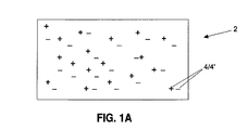
図1Aは、実質的に均一な様式で中に分散された陽イオンおよび陰イオン4および4’を有する例示的なイオン伝導性ポリマー2の概略図を示す。図1Aのイオン伝導性ポリマーは、電場を印加する前の潜在的なポリマー構造を表すと考えられる。図1Bは、中に配置された陽イオンおよび陰イオン4および4’を含むイオン伝導性チャネル8を有する例示的なイオン伝導性ポリマー6の概略図を示す。図1Bのイオン伝導性ポリマーは、電場の存在下で形成され得るポリマー構造を表すと考えられる。図1Bは、イオン伝導性チャネル8を実質的にまっすぐであるように示しているが、チャネルは、電流がこれを通って流れるのを可能にする任意の形状のものとすることができることが認識されるはずである。
FIG. 1A shows a schematic diagram of an exemplary
いくつかの実施形態では、イオン伝導性ポリマーを作製するための方法は、電解質およびポリマー前駆体を含有する混合物を提供する工程と、混合物に電場を印加しながらポリマー前駆体を重合させる工程とを含む。 In some embodiments, a method for making an ion conducting polymer comprises providing a mixture containing an electrolyte and a polymer precursor and polymerizing the polymer precursor while applying an electric field to the mixture. Including.
一般に、混合物への電場の印加は、電極を混合物と接触させ、そこに電流を印加することによって行うことができる。いくつかの実施形態では、交流電流を混合物に印加することができる。しかし、他の実施形態では、直流も、そのように望まれる場合、利用することができることが認識されるべきである。 In general, application of an electric field to the mixture can be performed by bringing an electrode into contact with the mixture and applying an electric current thereto. In some embodiments, an alternating current can be applied to the mixture. However, it should be appreciated that in other embodiments, direct current can also be utilized if so desired.
いくつかの実施形態では、電解質は、重合を行った後、ポリマーマトリックス内に均一に分散させることができる。他の実施形態では、電解質は、重合を行った後、ポリマーマトリックス内に不均一に分散させ、または勾配のある様式で分散させることができる。いくつかの実施形態では、電解質は、重合を行った後、イオン伝導性ポリマーのポリマーマトリックス内の伝導性イオンチャネル内に存在し得る。 In some embodiments, the electrolyte can be uniformly dispersed within the polymer matrix after polymerization. In other embodiments, the electrolyte can be dispersed non-uniformly within the polymer matrix after polymerization or in a gradient manner. In some embodiments, the electrolyte may be present in a conductive ion channel within the polymer matrix of the ion conductive polymer after performing the polymerization.
一般に、本実施形態を実行するのに、任意のタイプのポリマー前駆体を使用することができる。いくつかの実施形態では、ポリマー前駆体は、エポキシ樹脂とすることができ、これは、自己硬化性エポキシ樹脂であっても、2成分エポキシ樹脂であってもよい。いくつかの実施形態では、ポリマー前駆体は、熱可塑性ポリマーまたは熱硬化性ポリマーをもたらす重合性モノマーとすることができる。当業者は、イオン伝導性ポリマーの最終用途が分かり、本開示の利点を有する適切なポリマーマトリックスを選ぶことができるであろう。 In general, any type of polymer precursor can be used to perform this embodiment. In some embodiments, the polymer precursor can be an epoxy resin, which can be a self-curing epoxy resin or a two-component epoxy resin. In some embodiments, the polymer precursor can be a polymerizable monomer that results in a thermoplastic polymer or a thermosetting polymer. One skilled in the art will know the end use of the ion conducting polymer and will be able to select a suitable polymer matrix having the advantages of the present disclosure.
本実施形態で使用するのに適したものとなり得る例示的な熱可塑性ポリマーとして、例えば、ポリプロピレン、ポリエチレン、ポリアクリロニトリル(PAN)、フッ化ポリビニリデン(PVDF)、ポリスチレン、ポリアミド、ポリカーボネート、ポリスルホン、ポリイミド、ポリエーテルイミド、ポリエーテルエーテルケトン、硫化ポリフェニレンなどを挙げることができる。他の適当な熱可塑性ポリマーも、当業者によって想定され得る。 Exemplary thermoplastic polymers that may be suitable for use in this embodiment include, for example, polypropylene, polyethylene, polyacrylonitrile (PAN), polyvinylidene fluoride (PVDF), polystyrene, polyamide, polycarbonate, polysulfone, polyimide , Polyetherimide, polyetheretherketone, polyphenylene sulfide and the like. Other suitable thermoplastic polymers can also be envisioned by those skilled in the art.
本実施形態で使用するのに適したものとなり得る例示的な熱硬化性ポリマーとして、例えば、フタル酸/マレイン酸型ポリエステル、ビニルエステル、エポキシ、フェノール樹脂、シアネート、ビスマレイミド、ナド酸(nadic)エンドキャップポリイミド(例えば、PMR−15)などを挙げることができる。他の適当な熱硬化性ポリマーも、当業者によって想定され得る。 Exemplary thermosetting polymers that may be suitable for use in this embodiment include, for example, phthalic acid / maleic acid type polyesters, vinyl esters, epoxies, phenolic resins, cyanates, bismaleimides, nadic acids. An end cap polyimide (for example, PMR-15) can be used. Other suitable thermosetting polymers can also be envisioned by those skilled in the art.
一般に、任意のタイプの電解質を、本実施形態によるポリマー前駆体とともに組み込むことができる。いくつかの実施形態では、電解質は、無機電解質とすることができる。他の実施形態では、電解質は、イオン液体を含めた有機電解質とすることができる。当業者は、電解質の有効サイズは、そのイオン移動度に影響を与える場合があり、これは、重合後に得られるポリマーのイオン伝導性に影響を与えることを認識するであろう。当業者は、最終用途およびイオン伝導性の所望の程度に応じて、所与の用途に適切な電解質を選ぶことができるであろう。 In general, any type of electrolyte can be incorporated with the polymer precursor according to this embodiment. In some embodiments, the electrolyte can be an inorganic electrolyte. In other embodiments, the electrolyte can be an organic electrolyte including an ionic liquid. One skilled in the art will recognize that the effective size of an electrolyte can affect its ionic mobility, which affects the ionic conductivity of the resulting polymer after polymerization. One skilled in the art will be able to select the appropriate electrolyte for a given application, depending on the end use and the desired degree of ionic conductivity.
本実施形態によれば、無機電解質は、水相内に入った電解質無機化合物を含むことができる。このような無機電解質として、例えば、酸性水溶液(例えば、硫酸、リン酸、塩酸など)、塩基水溶液(例えば、水酸化ナトリウム、水酸化カリウムなど)、および中性塩溶液を挙げることができる。中性塩溶液を形成するのに使用することができる例示的な塩として、例えば、塩化ナトリウム、塩化カリウム、酸化ナトリウム、酸化カリウム、硫酸ナトリウム、硫酸カリウムなどを挙げることができる。追加の水性電解質も、当業者によって想定され得る。いくつかの実施形態では、無機電解質は、リチウムイオン水溶液とすることができる。当業者が認識するように、水溶液内の無機電解質は、低内部抵抗値をもたらし得るが、一般に、対称(symmetric)システムについて約1V、および非対称(asymmetric)システムについて約2Vの上方使用電圧範囲に制限される。 According to this embodiment, the inorganic electrolyte can include an electrolyte inorganic compound that has entered the aqueous phase. Examples of such inorganic electrolytes include acidic aqueous solutions (eg, sulfuric acid, phosphoric acid, hydrochloric acid, etc.), basic aqueous solutions (eg, sodium hydroxide, potassium hydroxide, etc.), and neutral salt solutions. Exemplary salts that can be used to form a neutral salt solution include, for example, sodium chloride, potassium chloride, sodium oxide, potassium oxide, sodium sulfate, potassium sulfate, and the like. Additional aqueous electrolytes can also be envisioned by those skilled in the art. In some embodiments, the inorganic electrolyte can be an aqueous lithium ion solution. As those skilled in the art will appreciate, inorganic electrolytes in aqueous solutions can provide low internal resistance values, but generally in the upper working voltage range of about 1V for symmetric systems and about 2V for asymmetric systems. Limited.
本実施形態によれば、有機電解質は、有機溶媒中に溶解した電解質種を含むことができる。例示的な電解質種として、例えば、テトラアルキルアンモニウム塩(例えば、ハロゲン化テトラエチルアンモニウムもしくはハロゲン化テトラメチルアンモニウムおよび水酸化テトラエチルアンモニウムもしくは水酸化テトラメチルアンモニウム);4級ホスホニウム塩;ならびにリチウム、ナトリウム、またはカリウムのテトラフルオロホウ酸塩、過塩素酸塩、ヘキサフルオロホスフェート、ビス(トリフルオロメタン)スルホネート、ビス(トリフルオロメタン)スルホニルイミド、またはトリス(トリフルオロメタン)スルホニルメチド(sulfonylmethide)を挙げることができる。 According to this embodiment, the organic electrolyte can include an electrolyte species dissolved in an organic solvent. Exemplary electrolyte species include, for example, tetraalkylammonium salts (eg, tetraethylammonium halide or tetramethylammonium halide and tetraethylammonium hydroxide or tetramethylammonium hydroxide); quaternary phosphonium salts; and lithium, sodium, or Mention may be made of potassium tetrafluoroborate, perchlorate, hexafluorophosphate, bis (trifluoromethane) sulfonate, bis (trifluoromethane) sulfonylimide, or tris (trifluoromethane) sulfonylmethide.
有機電解質とともに使用される有機溶媒は、一般に、高誘電率を有する非プロトン性有機溶媒である。当業者が認識するように、このような溶媒中の有機電解質は、最大約4Vの使用電圧範囲を有することができるが、水溶液中で無機電解質が有するより高い内部抵抗を有する場合がある。有機電解質とともに使用することができる例示的な有機溶媒として、例えば、炭酸アルキル(例えば、炭酸プロピレン、炭酸エチレン、炭酸ブチレン、炭酸ジメチル、炭酸ジエチル、炭酸ジプロピル、炭酸メチルエチル、炭酸メチルブチル、炭酸メチルプロピル、炭酸エチルプロピル、炭酸ブチルプロピル、1,2−ブチレンカーボネート、2,3−ブチレンカーボネート、1,2−ペンテンカーボネート、および2,3−ペンテンカーボネート)、ニトリル(例えば、アセトニトリル、アクリロニトリル、プロピオニトリル、ブチロニトリル、およびベンゾニトリル)、スルホキシド(例えば、ジメチルスルホキシド、ジエチルスルホキシド、エチルメチルスルホキシド、およびベンジルメチルスルホキシド)、アミド(例えば、ホルムアミド、メチルホルムアミド、およびジメチルホルムアミド)、ピロリドン(例えば、N−メチルピロリドン)、ラクトン(例えば、γ−ブチロラクトン、γ−バレロラクトン、2−メチル−γ−ブチロラクトン、およびアセチル−γ−ブチロラクトン)、ホスフェートトリエステル、ニトロメタン、エーテル(例えば、1,2−ジメトキシエタン;1,2−ジエトキシエタン;1,2−メトキシエトキシエタン;1,2−または1,3−ジメトキシプロパン;1,2−または1,3−ジエトキシプロパン;1,2−または1,3−エトキシメトキシプロパン;1,2−ジブトキシエタン;テトラヒドロフラン;2−メチルテトラヒドロフラン、および他のアルキル、ジアルキル、アルコキシまたはジアルコキシテトラヒドロフラン;1,4−ジオキサン;1,3−ジオキソラン;1,4−ジオキソラン;2−メチル−1,3−ジオキソラン;4−メチル−1,3−ジオキソラン;スルホラン;3−メチルスルホラン;メチルエーテル;エチルエーテル;プロピルエーテル;ジエチレングリコールジアルキルエーテル;トリエチレングリコールジアルキルエーテル;エチレングリコールジアルキルエーテル;およびテトラエチレングリコールジアルキルエーテル)、エステル(例えば、プロピオン酸アルキル、例えば、プロピオン酸メチルおよびプロピオン酸エチルなど、マロン酸ジアルキル、例えば、マロン酸ジエチルなど、酢酸アルキル、例えば、酢酸メチルおよび酢酸エチルなど、ならびにギ酸アルキル、例えば、ギ酸メチルおよびギ酸エチルなど);ならびに無水マレイン酸が挙げられる。さらに、有機ゲルなども必要に応じて使用することができる。 The organic solvent used with the organic electrolyte is generally an aprotic organic solvent having a high dielectric constant. As those skilled in the art will appreciate, an organic electrolyte in such a solvent can have a working voltage range of up to about 4 V, but may have a higher internal resistance than an inorganic electrolyte in aqueous solution. Exemplary organic solvents that can be used with the organic electrolyte include, for example, alkyl carbonates (eg, propylene carbonate, ethylene carbonate, butylene carbonate, dimethyl carbonate, diethyl carbonate, dipropyl carbonate, methyl ethyl carbonate, methyl butyl carbonate, methyl propyl carbonate). , Ethylpropyl carbonate, butylpropyl carbonate, 1,2-butylene carbonate, 2,3-butylene carbonate, 1,2-pentene carbonate, and 2,3-pentene carbonate), nitriles (eg, acetonitrile, acrylonitrile, propionitrile) , Butyronitrile, and benzonitrile), sulfoxides (eg, dimethyl sulfoxide, diethyl sulfoxide, ethylmethyl sulfoxide, and benzylmethyl sulfoxide), amides (eg, formaldehyde) , Methylformamide, and dimethylformamide), pyrrolidone (eg, N-methylpyrrolidone), lactone (eg, γ-butyrolactone, γ-valerolactone, 2-methyl-γ-butyrolactone, and acetyl-γ-butyrolactone), phosphate Triester, nitromethane, ether (eg, 1,2-dimethoxyethane; 1,2-diethoxyethane; 1,2-methoxyethoxyethane; 1,2- or 1,3-dimethoxypropane; 1,2- or 1 1,2- or 1,3-ethoxymethoxypropane; 1,2-dibutoxyethane; tetrahydrofuran; 2-methyltetrahydrofuran and other alkyl, dialkyl, alkoxy or dialkoxytetrahydrofuran; 4-Geo 1,3-dioxolane; 1,4-dioxolane; 2-methyl-1,3-dioxolane; 4-methyl-1,3-dioxolane; sulfolane; 3-methylsulfolane; methyl ether; ethyl ether; Diethylene glycol dialkyl ethers; triethylene glycol dialkyl ethers; ethylene glycol dialkyl ethers; and tetraethylene glycol dialkyl ethers), esters (eg alkyl propionates such as methyl propionate and ethyl propionate, such as dialkyl malonates such as malonic acid Such as diethyl, alkyl acetates such as methyl acetate and ethyl acetate, and alkyl formates such as methyl formate and ethyl formate); and maleic anhydride. It is. Furthermore, an organic gel etc. can be used as needed.
いくつかの実施形態では、電解質は、イオン液体、例えば、ベンジルジメチルプロピルアンモニウムアルミニウムテトラクロレート、ベンジルジメチルアンモニウムイミド、エチルメチルアンモニウムビスルフェート、1−ブチル−3−メチルイミダゾリウムテトラフルオロボレート、またはテトラエチルアンモニウムテトラフルオロボレートなどとすることができる。上記有機溶媒のいずれも、このようなイオン液体と組み合わせて任意選択により使用することができる。 In some embodiments, the electrolyte is an ionic liquid, such as benzyldimethylpropylammonium aluminum tetrachlorate, benzyldimethylammonium imide, ethylmethylammonium bisulphate, 1-butyl-3-methylimidazolium tetrafluoroborate, or tetraethylammonium. Tetrafluoroborate can be used. Any of the above organic solvents can be optionally used in combination with such an ionic liquid.
様々な実施形態では、電解質がイオン伝導性ポリマー中に分散されているときに理論的に達成可能な最大伝導率が、電解質溶液自体の最大伝導率である。すなわち、イオン伝導性ポリマーの伝導率は、これが形成される電解質溶液の伝導率より大きくないことが一般に事実である。当業者がさらに認識するように、本イオン伝導性ポリマーの伝導率は、中に組み込まれる電解質の量に少なくとも部分的に起因することになる。先に述べたように、イオン伝導性ポリマー中の電解質の量は、ポリマーの機械的強度に影響を与え得る。しかし、本実施形態によって調製されるイオン伝導性ポリマーは、同様の電解質濃度で伝導率値の増強を示し、それによって、より低い電解質濃度でより良好な機械特性値をもたらすことができる。 In various embodiments, the maximum conductivity that is theoretically achievable when the electrolyte is dispersed in the ion conducting polymer is the maximum conductivity of the electrolyte solution itself. That is, it is generally true that the conductivity of the ion conducting polymer is not greater than the conductivity of the electrolyte solution in which it is formed. As those skilled in the art will further appreciate, the conductivity of the ionically conductive polymer will be due at least in part to the amount of electrolyte incorporated therein. As previously mentioned, the amount of electrolyte in the ion conducting polymer can affect the mechanical strength of the polymer. However, ion conducting polymers prepared according to this embodiment can exhibit enhanced conductivity values at similar electrolyte concentrations, thereby providing better mechanical property values at lower electrolyte concentrations.
様々な実施形態では、本イオン伝導性ポリマー内に組み込まれる電解質の量は、一般に、イオン伝導性ポリマーの約0.1質量%〜約90質量%の間の範囲となり得る。いくつかの実施形態では、本イオン伝導性ポリマー内の電解質の量は、約5質量%〜約90質量%の間の範囲となり得る。いくつかの実施形態では、本イオン伝導性ポリマー内の電解質の量は、約10質量%〜約80質量%の間の範囲となり得る。いくつかの実施形態では、本イオン伝導性ポリマー内の電解質の量は、約20質量%〜約60質量%の間の範囲となり得る。いくつかの実施形態では、本イオン伝導性ポリマー内の電解質の量は、約1質量%〜約10質量%の間の範囲となり得る。いくつかの実施形態では、本イオン伝導性ポリマー内の電解質の量は、約10質量%〜約20質量%の間の範囲となり得る。いくつかの実施形態では、本イオン伝導性ポリマー内の電解質の量は、約20質量%〜約30質量%の間の範囲となり得る。いくつかの実施形態では、本イオン伝導性ポリマー内の電解質の量は、約30質量%〜約40質量%の間の範囲となり得る。いくつかの実施形態では、本イオン伝導性ポリマー内の電解質の量は、約40質量%〜約50質量%の間の範囲となり得る。いくつかの実施形態では、本イオン伝導性ポリマー内の電解質の量は、約50質量%〜約60質量%の間の範囲となり得る。いくつかの実施形態では、本イオン伝導性ポリマー内の電解質の量は、約60質量%〜約70質量%の間の範囲となり得る。 In various embodiments, the amount of electrolyte incorporated within the ion conductive polymer can generally range between about 0.1% and about 90% by weight of the ion conductive polymer. In some embodiments, the amount of electrolyte in the ionically conductive polymer can range between about 5% to about 90% by weight. In some embodiments, the amount of electrolyte in the ionically conductive polymer can range between about 10% to about 80% by weight. In some embodiments, the amount of electrolyte in the ionically conductive polymer can range between about 20% to about 60% by weight. In some embodiments, the amount of electrolyte in the ionically conductive polymer can range between about 1% and about 10% by weight. In some embodiments, the amount of electrolyte in the ionically conductive polymer can range between about 10% and about 20% by weight. In some embodiments, the amount of electrolyte in the ionically conductive polymer can range between about 20% to about 30% by weight. In some embodiments, the amount of electrolyte in the ionically conductive polymer can range between about 30% to about 40% by weight. In some embodiments, the amount of electrolyte in the ionically conductive polymer can range between about 40% and about 50% by weight. In some embodiments, the amount of electrolyte in the ionically conductive polymer can range between about 50% to about 60% by weight. In some embodiments, the amount of electrolyte in the ionically conductive polymer can range between about 60% to about 70% by weight.
先に述べたように、イオン伝導性ポリマーのイオン伝導性は、中に存在する電解質の量によって、少なくとも部分的に影響を与えられ得る。いくつかの実施形態では、イオン伝導性ポリマーは、少なくとも約1×10−5S/cmの伝導率を有することができる。いくつかの実施形態では、イオン伝導性ポリマーは、少なくとも約5×10−5S/cmの伝導率を有することができる。いくつかの実施形態では、イオン伝導性ポリマーは、少なくとも約1×10−4S/cmの伝導率を有することができる。いくつかの実施形態では、イオン伝導性ポリマーは、少なくとも約5×10−4S/cmの伝導率を有することができる。いくつかの実施形態では、イオン伝導性ポリマーは、少なくとも約1×10−3S/cmの伝導率を有することができる。いくつかの実施形態では、イオン伝導性ポリマーは、少なくとも約5×10−3S/cmの伝導率を有することができる。いくつかの実施形態では、イオン伝導性ポリマーは、約7.5×10−3S/cm〜約1×10−4S/cmの間の範囲の伝導率を有することができる。いくつかの実施形態では、イオン伝導性ポリマーは、約5×10−3S/cm〜約1×10−4S/cmの間の範囲の伝導率を有することができる。いくつかの実施形態では、イオン伝導性ポリマーは、約1×10−3S/cm〜約1×10−4S/cmの間の範囲の伝導率を有することができる。いくつかの実施形態では、イオン伝導性ポリマーの伝導率は、元となる電解質溶液の最大伝導率の少なくとも約25%であり得る。いくつかの実施形態では、イオン伝導性ポリマーの伝導率は、元となる電解質溶液の最大伝導率の少なくとも約10%であり得る。いくつかの実施形態では、イオン伝導性ポリマーの伝導率は、元となる電解質溶液の最大伝導率の少なくとも約5%であり得る。いくつかの実施形態では、イオン伝導性ポリマーの伝導率は、元となる電解質溶液の最大伝導率の少なくとも約1%であり得る。 As previously mentioned, the ionic conductivity of an ion conducting polymer can be influenced at least in part by the amount of electrolyte present therein. In some embodiments, the ion conductive polymer can have a conductivity of at least about 1 × 10 −5 S / cm. In some embodiments, the ion conductive polymer can have a conductivity of at least about 5 × 10 −5 S / cm. In some embodiments, the ion conducting polymer can have a conductivity of at least about 1 × 10 −4 S / cm. In some embodiments, the ion conducting polymer can have a conductivity of at least about 5 × 10 −4 S / cm. In some embodiments, the ion conducting polymer can have a conductivity of at least about 1 × 10 −3 S / cm. In some embodiments, the ion conducting polymer can have a conductivity of at least about 5 × 10 −3 S / cm. In some embodiments, the ion conducting polymer can have a conductivity in the range of between about 7.5 × 10 −3 S / cm and about 1 × 10 −4 S / cm. In some embodiments, the ion conducting polymer can have a conductivity in the range of between about 5 × 10 −3 S / cm and about 1 × 10 −4 S / cm. In some embodiments, the ion conducting polymer can have a conductivity in the range of between about 1 × 10 −3 S / cm and about 1 × 10 −4 S / cm. In some embodiments, the conductivity of the ion conducting polymer can be at least about 25% of the maximum conductivity of the original electrolyte solution. In some embodiments, the conductivity of the ion conducting polymer can be at least about 10% of the maximum conductivity of the original electrolyte solution. In some embodiments, the conductivity of the ion conducting polymer can be at least about 5% of the maximum conductivity of the original electrolyte solution. In some embodiments, the conductivity of the ion conducting polymer can be at least about 1% of the maximum conductivity of the original electrolyte solution.
様々な実施形態では、本明細書に記載される方法によって調製されるイオン伝導性ポリマーは、ポリマー前駆体を重合する間に電場を印加することなく作製されるイオン伝導性ポリマーが有するより、良好な機械特性値を有することができる。すなわち、本イオン伝導性ポリマーは、従来の合成技法を使用して調製されるものより良好な機械特性を有することができる。例えば、いくつかの実施形態では、本イオン伝導性ポリマーは、ポリマー前駆体を重合する間に電場を印加することなく作製される同等のイオン伝導性ポリマーが有するより、高い圧縮剛性を有することができる。 In various embodiments, an ion conducting polymer prepared by the methods described herein is better than an ion conducting polymer made without applying an electric field while polymerizing a polymer precursor. Can have various mechanical property values. That is, the ionically conductive polymer can have better mechanical properties than those prepared using conventional synthetic techniques. For example, in some embodiments, the ionically conductive polymer may have a higher compressive stiffness than does an equivalent ionically conductive polymer made without applying an electric field while polymerizing the polymer precursor. it can.
いくつかの実施形態では、イオン伝導性ポリマーは、充填材も含有することができる。いくつかの目的は、充填材によって提供され得る。例えば、いくつかの実施形態では、充填材は、イオン伝導性ポリマーの機械的強度をさらに改善することができる。他の実施形態では、充填材は、イオン伝導性ポリマーの熱伝導率および温度安定性を改善することができる。適当な充填材は、ポリマー複合体中に慣例的に使用されるものを含むことができ、例えば、金属、金属酸化物、非金属元素、ならびに連続繊維、チョップド繊維の形態でのヘテロポリ酸、粒子材料(例えば、カーボンブラックおよびグラファイト)、ナノ粒子材料(例えば、金属ナノ粒子、カーボンナノチューブ、およびグラフェン)などを含むことができる。繊維のタイプは、金属繊維、セラミック繊維、有機繊維、炭素繊維、ガラス繊維などを含む。いくつかの実施形態では、カーボンナノチューブ導入繊維(carbon nanotube-infused fiber)を充填材として含めることができる。カーボンナノチューブ導入繊維に関するさらなる詳細を、以下により詳細に示す。 In some embodiments, the ion conducting polymer can also contain a filler. Some purposes may be provided by the filler. For example, in some embodiments, the filler can further improve the mechanical strength of the ion conducting polymer. In other embodiments, the filler can improve the thermal conductivity and temperature stability of the ion conducting polymer. Suitable fillers can include those conventionally used in polymer composites, such as metals, metal oxides, non-metallic elements, and heteropolyacids, particles in the form of continuous fibers, chopped fibers. Materials (eg, carbon black and graphite), nanoparticle materials (eg, metal nanoparticles, carbon nanotubes, and graphene) and the like can be included. Fiber types include metal fibers, ceramic fibers, organic fibers, carbon fibers, glass fibers, and the like. In some embodiments, carbon nanotube-infused fiber can be included as a filler. Further details regarding the carbon nanotube-introduced fibers are given in more detail below.
存在する場合、充填材は、イオン伝導性ポリマーの最大50重量%までのゼロでない量でイオン伝導性ポリマー中に存在することができる。いくつかの実施形態では、充填材は、約0.1重量%〜約50重量%の間の範囲の量で存在し得る。他の実施形態では、充填材は、約1重量%〜約45重量%の間の範囲の量で存在し得る。さらに他の実施形態では、充填材は、約5重量%〜約40重量%または約10重量%〜約50重量%の間の範囲の量で存在し得る。 When present, the filler can be present in the ion conductive polymer in a non-zero amount up to 50% by weight of the ion conductive polymer. In some embodiments, the filler may be present in an amount ranging between about 0.1% to about 50% by weight. In other embodiments, the filler may be present in an amount ranging between about 1 wt% and about 45 wt%. In still other embodiments, the filler may be present in an amount ranging from about 5% to about 40% or from about 10% to about 50% by weight.
他の様々な実施形態では、本開示のイオン伝導性ポリマーを含有する電気デバイスが本明細書に記載されている。本明細書において、用語「電気デバイス」は、電荷を貯蔵し、伝達する任意のデバイスを指すことになる。本イオン伝導性ポリマーを含有する電気デバイスは、イオン伝導性ポリマーがポリマー前駆体を重合させながら電場を印加しないで調製される場合より、良好な機械的強度値を有しながら高レベルの導電率を同時に示すことができる。いくつかの実施形態では、本イオン伝導性ポリマーを含有する電気デバイスは、ワイヤーまたは導電性シートの形態であり得る。いくつかの実施形態では、本明細書に記載されるイオン伝導性ポリマーは、従来のバッテリー、電解コンデンサー、およびスーパーキャパシタの電解質に取って代わることができる。 In various other embodiments, electrical devices containing the ionically conductive polymers of the present disclosure are described herein. As used herein, the term “electrical device” will refer to any device that stores and transfers charge. Electrical devices containing the present ion-conducting polymer have a higher level of electrical conductivity with better mechanical strength values than when the ion-conducting polymer is prepared without polymerizing the polymer precursor and without applying an electric field. Can be shown simultaneously. In some embodiments, the electrical device containing the ionically conductive polymer can be in the form of a wire or conductive sheet. In some embodiments, the ion conducting polymers described herein can replace the electrolytes of conventional batteries, electrolytic capacitors, and supercapacitors.
いくつかの実施形態では、本明細書に記載される電気デバイスは、第1の電極および第2の電極を含有することができる。いくつかの実施形態では、本明細書に記載される電気デバイスは、第1の電極および第2の電極を含有することができ、ここで、本明細書に記載されるイオン伝導性ポリマーは、電極を互いに電気連絡するように維持することができる。いくつかの実施形態では、電気デバイスは、第1の電極と第2の電極との間の電荷分離を維持するセパレータ材料も含有することができる。 In some embodiments, the electrical devices described herein can contain a first electrode and a second electrode. In some embodiments, an electrical device described herein can contain a first electrode and a second electrode, wherein the ion conductive polymer described herein is: The electrodes can be maintained in electrical communication with each other. In some embodiments, the electrical device can also contain a separator material that maintains charge separation between the first electrode and the second electrode.
いくつかの実施形態では、本明細書に記載される電気デバイスは、第1の電極層、第2の電極層、およびイオン透過性を有し、これらの間に配置されたセパレータ材料層を有する層状構造を含有することができる。電気デバイスは、層状構造に浸透するイオン伝導性ポリマーも含有することができ、ここで、イオン伝導性ポリマーは、電解質、および電場の存在下で重合されたポリマーマトリックスを含有する。 In some embodiments, an electrical device described herein has a first electrode layer, a second electrode layer, and a separator material layer that is ion permeable and disposed therebetween. Layered structures can be included. The electrical device can also contain an ion conducting polymer that penetrates the layered structure, where the ion conducting polymer contains an electrolyte and a polymer matrix polymerized in the presence of an electric field.
いくつかの実施形態では、層状電気デバイスを作製するための方法は、第1の電極層、第2の電極層、およびイオン透過性を有し、これらの間に配置されたセパレータ材料層を有する層状構造を提供する工程と、電解質およびポリマー前駆体を含有する混合物を提供する工程と、層状構造に混合物を浸透させる工程と、混合物に電場を印加しながらポリマー前駆体を重合させる工程とを含む。 In some embodiments, a method for making a layered electrical device includes a first electrode layer, a second electrode layer, and a separator material layer disposed between and having ion permeability. Providing a layered structure, providing a mixture containing an electrolyte and a polymer precursor, infiltrating the mixture into the layered structure, and polymerizing the polymer precursor while applying an electric field to the mixture. .
図2は、本実施形態によって調製されるイオン伝導性ポリマーを含有する例示的な層状電気デバイスの概略図を示す。図2に示したように、電気デバイス1は、カソード層3およびアノード層5を、これらの間のイオン伝導性ポリマー9とともに含有する。電気デバイス1内の電荷分離は、セパレータ材料層7によって維持され、これは、イオン伝導性ポリマー9内の電解質のイオンが透過できる。
FIG. 2 shows a schematic diagram of an exemplary layered electrical device containing an ion conducting polymer prepared according to this embodiment. As shown in FIG. 2, the electrical device 1 contains a cathode layer 3 and an
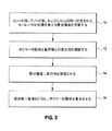
図3は、層状電気デバイスを、本実施形態のいくつかによってどのように作製することができるかを例示する流れ図を示す。図3に示したように、カソード層、アノード層、およびこれらの間に配置されたセパレータ材料層を有する層状構造は、操作10で作製される。操作12では、ポリマー前駆体、電解質、および任意選択により溶媒の混合物が調製される。操作14では、混合物が層状構造中に浸透させられ、その結果、ポリマー前駆体および電解質がカソード層とセパレータ材料層の間、およびアノード層とセパレータ材料層の間に配置される。最後に、操作16では、ポリマー前駆体が、混合物に電場を印加しながら重合される。
FIG. 3 shows a flow diagram illustrating how a layered electrical device can be made according to some of the embodiments. As shown in FIG. 3, a layered structure having a cathode layer, an anode layer, and a separator material layer disposed therebetween is made in
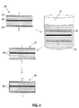
本実施形態による層状電気デバイスを作製するためのプロセスを、図4に概略的に例示する。図4は、層状電気デバイスを本実施形態によって作製することができる例示的方法を例示する概略図を示す。図4に示したように、カソード層22、アノード層24、およびこれらの間に配置されたセパレータ材料層26を含有する層状構造20が形成される。一実施形態では、層状構造20は、様々な層を単に積み重ねることによって作製することができる。次いで、層状構造20は、ポリマー前駆体および電解質を含有する混合物30を浸透させられることができる。一実施形態では、層状構造20中への十分な程度の浸透が達成されるまで、層状構造20を混合物30のリザーバ31内に浸漬することができる。例えば、加圧浸透またはバキュームバック浸透(vacuum back infiltration)を含めた他の浸透技法も当業者によって想定され得る。次いで、混合物30が層状構造20に浸透した後、この混合物に電流を印加しながらポリマー前駆体の重合を行うことができる。例えば、交流電流をカソード層22およびアノード層24にわたって確立することによって、混合物30内に電場をもたらすことができる。層状構造20内の混合物30に電場を印加しながら、次いでポリマーを重合させることによって、層状構造20内でイオン伝導性ポリマー32を形成することができる。当業者は、特定のポリマー前駆体に適したものとなる適切な重合技法を認識するであろう。例えば、様々な実施形態では、ポリマー前駆体の重合は、加熱、開始剤の添加によって、または光開始を通じて開始することができる。
A process for fabricating a layered electrical device according to this embodiment is schematically illustrated in FIG. FIG. 4 shows a schematic diagram illustrating an exemplary method by which a layered electrical device can be fabricated according to this embodiment. As shown in FIG. 4, a
電気デバイスのセパレータ材料は、帯電状態が得られた後に電解質イオンの電荷分離を維持することができる十分な厚さの任意の物質から形成することができる。一般に、セパレータ材料は、本質的に多孔質であって、電気デバイスが帯電または放電している間に電極材料同士間で高イオン移動度を可能にするが、電気デバイスが帯電状態に到達した後に電荷分離を維持することができる薄膜誘電体とすることができる。したがって、セパレータ材料は、電解質の電荷担体について選択的に透過性となり得る。いくつかの実施形態では、セパレータ材料は、不織のポリマー布地、例えば、ポリエチレン不織布、ポリプロピレン不織布、ポリエステル不織布、およびポリアクリロニトリル不織布などとすることができる。他の実施形態では、セパレータ材料は、多孔質物質、例えば、多孔質ポリ(フッ化ビニリデン)−ヘキサフルオロプロパンコポリマー膜、多孔質セルロース膜、クラフト紙、レーヨン織物などとすることができる。一般に、バッテリーで使用することができる任意のセパレータ材料も、同様の目的について、本実施形態において使用することができる。 The separator material of the electrical device can be formed from any substance of sufficient thickness that can maintain charge separation of electrolyte ions after a charged state is obtained. In general, the separator material is porous in nature and allows high ion mobility between electrode materials while the electrical device is charged or discharged, but after the electrical device reaches a charged state. It can be a thin film dielectric capable of maintaining charge separation. Thus, the separator material can be selectively permeable to the charge carrier of the electrolyte. In some embodiments, the separator material can be a nonwoven polymer fabric, such as a polyethylene nonwoven fabric, a polypropylene nonwoven fabric, a polyester nonwoven fabric, and a polyacrylonitrile nonwoven fabric. In other embodiments, the separator material can be a porous material, such as a porous poly (vinylidene fluoride) -hexafluoropropane copolymer membrane, porous cellulose membrane, kraft paper, rayon fabric, and the like. In general, any separator material that can be used in a battery can also be used in this embodiment for similar purposes.
セパレータ材料の多孔度の程度は、電解質のイオンが、デバイスが帯電または放電されているときにセパレータ材料を横断するように十分可動性であるが、デバイスが帯電状態に到達した後に電荷分離を維持するように十分に固定されているものである。いくつかの実施形態では、セパレータ材料の多孔度は、約90%超であり得る。いくつかの実施形態では、セパレータ材料の多孔度は、約90%〜約95%の間の範囲となり得る。他の実施形態では、セパレータ材料の多孔度は、約90%〜約40%の間、または約87%〜約50%の間、または約85%〜約65%の間の範囲となり得る。 The degree of porosity of the separator material is sufficiently mobile so that electrolyte ions can traverse the separator material when the device is charged or discharged, but maintain charge separation after the device reaches a charged state It is something that is fixed enough to do. In some embodiments, the porosity of the separator material can be greater than about 90%. In some embodiments, the porosity of the separator material can range between about 90% to about 95%. In other embodiments, the porosity of the separator material can range between about 90% to about 40%, or between about 87% to about 50%, or between about 85% to about 65%.
多孔度に加えて、セパレータ材料層の厚さも、セパレータ材料を横断するイオン移動度の程度を支配し得る。所与の多孔度について、より厚いセパレータ材料は一般に、より薄いセパレータ材料がもたらすよりも、より大きい程度の短絡保護およびより低いイオン移動度をもたらし得る。いくつかの実施形態では、セパレータ材料層の厚さは、約100μm未満であり得る。いくつかの実施形態では、セパレータ材料層の厚さは、約100μm〜約50μmの間の範囲となり得る。いくつかの実施形態では、セパレータ材料層の厚さは、約50μm〜約25μmの間、または約25μm〜約10μmの間の範囲となり得る。いくつかの実施形態では、セパレータ材料層の厚さは、約10μm未満である場合がある。いくつかの実施形態では、セパレータ材料層の厚さは、約10μm〜約1μmの間の範囲となり得る。いくつかの実施形態では、セパレータ材料層の厚さは、約1μm未満である場合がある。いくつかの実施形態では、セパレータ材料層の厚さは、約100nm〜約1μmの間の範囲となり得る。 In addition to porosity, the thickness of the separator material layer can also dictate the degree of ion mobility across the separator material. For a given porosity, thicker separator materials can generally provide a greater degree of short circuit protection and lower ion mobility than do thinner separator materials. In some embodiments, the thickness of the separator material layer can be less than about 100 μm. In some embodiments, the thickness of the separator material layer can range between about 100 μm to about 50 μm. In some embodiments, the thickness of the separator material layer can range between about 50 μm and about 25 μm, or between about 25 μm and about 10 μm. In some embodiments, the thickness of the separator material layer may be less than about 10 μm. In some embodiments, the thickness of the separator material layer can range between about 10 μm to about 1 μm. In some embodiments, the thickness of the separator material layer may be less than about 1 μm. In some embodiments, the thickness of the separator material layer can range between about 100 nm to about 1 μm.
一実施形態では、適当なセパレータ材料は、高多孔度(例えば、>90%)ポリプロピレンおよび/またはポリエチレン電解膜とすることができる。このような電解膜は、Celgard LLC of Charlotte、North Carolinaから入手可能である。これらの電解膜は、高い電圧スタンドオフ能力を呈し、それによって、電極材料を隔離するためのより薄くより軽い膜を可能にする。いくつかの実施形態では、セルロース繊維セパレータ材料(例えば、クラフト紙)または不織ポリマーマット(例えば、ポリイミド繊維セパレータ)も使用することができる。 In one embodiment, a suitable separator material can be a high porosity (eg,> 90%) polypropylene and / or polyethylene electrolyte membrane. Such electrolytic membranes are available from Celgard LLC of Charlotte, North Carolina. These electrolytic membranes exhibit a high voltage standoff capability, thereby allowing a thinner and lighter membrane for isolating the electrode material. In some embodiments, a cellulose fiber separator material (eg, kraft paper) or a non-woven polymer mat (eg, polyimide fiber separator) can also be used.
本明細書のいくつかの実施形態では、カーボンナノチューブ導入繊維を利用することができる。例示的なカーボンナノチューブ導入繊維は、共通して所有されている米国特許出願第12/611,073号、同第12/611,101号、および同第12/611,103号により詳細に記載されており、それぞれは、2009年11月2日に出願され、その全体が参照により本明細書に組み込まれている。カーボンナノチューブ導入繊維およびこれらを生産するためのプロセスのさらなる詳細を以下に続ける。いくつかの実施形態では、カーボンナノチューブ導入繊維は、イオン伝導性ポリマー内に充填材として存在し得る。いくつかの実施形態または他の実施形態では、カーボンナノチューブ導入繊維は、本開示のイオン伝導性ポリマーを含有する電気デバイス内の少なくとも1つの電極層中に使用することができる。カーボンナノチューブ導入繊維を含有する例示的な電気デバイスは、それぞれ2011年3月2日に出願された、共有の米国特許出願第13/039,025号、および同第13/039,028号、ならびに2011年5月26日に出願された同第13/117,071号に記載されており、これらのそれぞれは、その全体が参照により本明細書に組み込まれている。これらの特許出願に記載された電気デバイスの構成は、例示の目的のためだけであり、記載された構成は、当業者によって容易に改変することができることが認識されるべきである。 In some embodiments herein, carbon nanotube-introduced fibers can be utilized. Exemplary carbon nanotube-introduced fibers are described in more detail in commonly owned U.S. patent application Ser. Nos. 12 / 611,073, 12 / 611,101, and 12 / 611,103. Each of which is filed on Nov. 2, 2009, which is incorporated herein by reference in its entirety. Further details of the carbon nanotube-introduced fibers and the process for producing them follow below. In some embodiments, the carbon nanotube-introduced fiber may be present as a filler within the ion conducting polymer. In some or other embodiments, carbon nanotube-introduced fibers can be used in at least one electrode layer in an electrical device containing an ion conducting polymer of the present disclosure. Exemplary electrical devices containing carbon nanotube-introduced fibers are described in commonly owned U.S. Patent Application Nos. 13 / 039,025 and 13 / 039,028, each filed on March 2, 2011, and No. 13 / 117,071, filed May 26, 2011, each of which is incorporated herein by reference in its entirety. It should be appreciated that the configurations of the electrical devices described in these patent applications are for illustrative purposes only and the described configurations can be readily modified by those skilled in the art.
本明細書において、用語「繊維」、「繊維材料」、または「フィラメント」は同等に、基本的な構造特徴として繊維成分を有する任意の材料を指す。本明細書において、用語「連続繊維」は、巻き取り可能な(spoolable)長さの繊維材料、例えば、個々のフィラメント、ヤーン、ロービング、トウ(tow)、テープ、リボン、織物および不織布、プライ(ply)、マットなどを指す。 As used herein, the terms “fiber”, “fiber material”, or “filament” equally refer to any material having a fiber component as a fundamental structural feature. As used herein, the term “continuous fiber” refers to a fiber material of spoolable length, such as individual filaments, yarns, rovings, tow, tapes, ribbons, woven and non-woven fabrics, plies ( ply), refers to mats, etc.
本明細書において、用語「巻き取り可能な長さ」または「巻き取り可能な寸法」は、同等に、長さが制限されていない少なくとも1つの寸法を有し、それによってカーボンナノチューブを導入した後に繊維材料をスプールまたはマンドレル上に保管することが可能になっている繊維材料を指す。「巻き取り可能な長さ」または「巻き取り可能な寸法」の繊維材料は、繊維材料へのカーボンナノチューブ導入のためのバッチ処理または連続処理のいずれかの使用を示す少なくとも1つの寸法を有する。 As used herein, the term “windable length” or “windable dimension” equally has at least one dimension that is not limited in length, thereby introducing a carbon nanotube. Refers to a fiber material that allows it to be stored on a spool or mandrel. A “rollable length” or “windable dimension” fiber material has at least one dimension that indicates the use of either a batch or continuous process for introducing carbon nanotubes into the fiber material.
本明細書において、用語「導入された」は、結合されていることを指し、「導入」は、結合のプロセスを指す。本明細書において、用語「カーボンナノチューブ導入繊維」または「カーボンナノチューブ導入繊維材料」は、同等に、繊維材料に結合されたカーボンナノチューブを有する繊維材料を指す。カーボンナノチューブの繊維材料へのこのような結合は、機械的付着、共有結合、イオン結合、π−π相互作用(π−スタッキング相互作用)、および/またはファンデルワールス力媒介物理吸着を伴うことができる。いくつかの実施形態では、カーボンナノチューブは、繊維材料に直接結合することができる。他の実施形態では、カーボンナノチューブは、バリアコーティング剤および/またはカーボンナノチューブの成長を媒介するのに使用される触媒ナノ粒子を介して、繊維材料に間接的に結合される場合がある。カーボンナノチューブが繊維材料に導入される特定の様式は、結合モチーフと呼ばれる場合がある。 As used herein, the term “introduced” refers to being bound, and “introducing” refers to the process of binding. As used herein, the term “carbon nanotube-introduced fiber” or “carbon nanotube-introduced fiber material” refers equally to a fiber material having carbon nanotubes bonded to the fiber material. Such bonding of carbon nanotubes to fiber material may involve mechanical attachment, covalent bonding, ionic bonding, π-π interaction (π-stacking interaction), and / or van der Waals force-mediated physical adsorption. it can. In some embodiments, the carbon nanotubes can be directly bonded to the fiber material. In other embodiments, the carbon nanotubes may be indirectly bound to the fiber material via a barrier coating agent and / or catalytic nanoparticles used to mediate the growth of the carbon nanotubes. The particular manner in which carbon nanotubes are introduced into the fiber material is sometimes referred to as a binding motif.
本明細書において、用語「ナノ粒子」は、等価な球径において約0.1nm〜約100nmの間の直径を有する粒子を指すが、ナノ粒子は、必ずしも形状が球状である必要はない。本明細書において、用語「触媒ナノ粒子」は、カーボンナノチューブ成長を媒介するための触媒活性を有するナノ粒子を指す。 As used herein, the term “nanoparticle” refers to a particle having an equivalent sphere diameter between about 0.1 nm and about 100 nm in diameter, although a nanoparticle need not necessarily be spherical in shape. As used herein, the term “catalytic nanoparticle” refers to a nanoparticle having catalytic activity to mediate carbon nanotube growth.
本明細書において、用語「サイズ剤(sizing agent)」または「サイズ剤(sizing)」は、一括して、繊維材料の完全性を保護し、繊維材料とマトリックス材料の間の表面相互作用を増強し、かつ/または繊維材料のある特定の物理的性質を変更および/もしくは増強するためのコーティング剤として、繊維材料の製造において使用される材料を指す。 As used herein, the terms “sizing agent” or “sizing” collectively protect the integrity of the fiber material and enhance the surface interaction between the fiber material and the matrix material. And / or a material used in the manufacture of fiber materials as a coating agent to alter and / or enhance certain physical properties of the fiber material.
カーボンナノチューブ導入繊維の繊維材料は一般に、限定することなく多様となり得、例えば、ガラス繊維、炭素繊維、金属繊維、セラミック繊維、および有機繊維(例えば、アラミド繊維)を挙げることができる。このようなカーボンナノチューブ導入繊維は、市販の連続繊維または連続繊維形態(例えば、繊維トウもしくは繊維テープ)から巻き取り可能な長さで容易に作製することができる。さらに、カーボンナノチューブの長さ、直径、および被覆密度は、上記で参照した方法によって容易に変更することができる。 The fiber material of the carbon nanotube-introduced fiber can generally vary without limitation, and examples thereof include glass fiber, carbon fiber, metal fiber, ceramic fiber, and organic fiber (for example, aramid fiber). Such a carbon nanotube-introduced fiber can be easily produced in a length capable of being wound from a commercially available continuous fiber or a continuous fiber form (for example, fiber tow or fiber tape). Furthermore, the length, diameter, and coating density of the carbon nanotubes can be easily changed by the method referred to above.
カーボンナノチューブの成長条件に応じて、カーボンナノチューブ導入繊維のカーボンナノチューブは、これらが繊維材料の表面に対して実質的に垂直であるように、またはこれらが繊維材料の長手方向軸に対して実質的に平行であるように配向させることもできる。本実施形態では、実質的に垂直なカーボンナノチューブを有するカーボンナノチューブ導入繊維を使用することによって、電解質のカーボンナノチューブ表面領域へのより良好な曝露を実現することができる。カーボンナノチューブが実質的に束ねられていない状態で存在するとき、これは特に当てはまる。カーボンナノチューブ導入繊維を作製するための上記で参照した方法は、実質的に垂直な配向および実質的に束ねられていない状態を達成するのに特によく適しており、それによって、本実施形態で使用するための大きな有効表面積を有するカーボンナノチューブ導入繊維を提供する。 Depending on the growth conditions of the carbon nanotubes, the carbon nanotubes of the carbon nanotube-introduced fibers can be substantially perpendicular to the surface of the fiber material or they can be substantially relative to the longitudinal axis of the fiber material. It can also be oriented so that it is parallel to. In this embodiment, better exposure of the electrolyte to the carbon nanotube surface region can be achieved by using carbon nanotube-introduced fibers having substantially vertical carbon nanotubes. This is especially true when the carbon nanotubes are present in a substantially unbundled state. The above-referenced method for making carbon nanotube-introduced fibers is particularly well suited to achieving a substantially vertical orientation and a substantially unbundled state, thereby being used in this embodiment A carbon nanotube-introduced fiber having a large effective surface area is provided.
様々な実施形態では、カーボンナノチューブは、約1μm〜約1000μmの間、または約1μm〜約500μmの間の範囲の長さを有することができる。いくつかの実施形態では、カーボンナノチューブは、約100μm〜約500μmの間の範囲の長さを有することができる。他の実施形態では、カーボンナノチューブは、約1μm〜約50μmの間、または約10μm〜約25μmの間の範囲の長さを有することができる。いくつかの実施形態では、カーボンナノチューブは、長さが実質的に均一である場合がある。 In various embodiments, the carbon nanotubes can have a length in the range between about 1 μm and about 1000 μm, or between about 1 μm and about 500 μm. In some embodiments, the carbon nanotubes can have a length ranging between about 100 μm and about 500 μm. In other embodiments, the carbon nanotubes can have a length ranging between about 1 μm and about 50 μm, or between about 10 μm and about 25 μm. In some embodiments, the carbon nanotubes can be substantially uniform in length.
カーボンナノチューブを繊維材料に導入するために、カーボンナノチューブは、繊維材料上で直接合成される。いくつかの実施形態では、これは、カーボンナノチューブ形成触媒(例えば、触媒ナノ粒子)を繊維材料上に最初に配置することによって達成される。この触媒堆積の前に、いくつかの準備プロセスを実施することができる。 In order to introduce carbon nanotubes into the fiber material, the carbon nanotubes are synthesized directly on the fiber material. In some embodiments, this is accomplished by first placing a carbon nanotube-forming catalyst (eg, catalyst nanoparticles) on the fiber material. Several preparatory processes can be performed prior to this catalyst deposition.
いくつかの実施形態では、繊維材料を、プラズマで任意選択により処理することによって、触媒を受け入れるための繊維表面を作製することができる。例えば、プラズマ処理されたガラス繊維材料は、カーボンナノチューブ形成触媒を堆積させることができる粗面化されたガラス繊維表面をもたらすことができる。いくつかの実施形態では、プラズマは、繊維表面を「浄化する」役割も果たす。したがって、繊維表面を「粗面化する」ためのプラズマプロセスは、触媒堆積を促進する。粗さは、一般的にナノメートルの規模である。プラズマ処理プロセスにおいて、深さ数ナノメートルおよび直径数ナノメートルのクレーターまたはくぼみが形成される。このような表面修飾は、限定することなく、アルゴン、ヘリウム、酸素、アンモニア、窒素、および水素を含めた、様々な異なるガスのうちの任意の1つまたは複数のプラズマを使用して実現することができる。さらに、繊維表面をプラズマ処理すると、いくつかの実施形態において有用となり得る官能基をこの表面に付加することができる。 In some embodiments, the fiber material can be optionally treated with a plasma to create a fiber surface for receiving the catalyst. For example, a plasma treated glass fiber material can provide a roughened glass fiber surface on which a carbon nanotube forming catalyst can be deposited. In some embodiments, the plasma also serves to “clean” the fiber surface. Thus, the plasma process for “roughening” the fiber surface facilitates catalyst deposition. Roughness is typically on the nanometer scale. In the plasma treatment process, craters or depressions are formed that are several nanometers in depth and several nanometers in diameter. Such surface modification may be achieved using any one or more of a variety of different gases, including but not limited to argon, helium, oxygen, ammonia, nitrogen, and hydrogen. Can do. Furthermore, plasma treatment of the fiber surface can add functional groups to this surface that may be useful in some embodiments.
いくつかの実施形態では、使用される繊維材料がこれに付随したサイズ剤材料を有する場合、このようなサイズ剤を、触媒堆積の前に任意選択により除去することができる。任意選択により、サイズ剤材料は、触媒堆積後に除去することができる。いくつかの実施形態では、サイズ剤材料の除去は、カーボンナノチューブ合成の間に、または予熱工程においてカーボンナノチューブ合成の直前に遂行することができる。他の実施形態では、一部のサイズ剤材料は、カーボンナノチューブ合成プロセス全体にわたって残っている場合がある。 In some embodiments, if the fiber material used has a sizing material associated with it, such sizing can be optionally removed prior to catalyst deposition. Optionally, the sizing material can be removed after catalyst deposition. In some embodiments, removal of the sizing material can be performed during carbon nanotube synthesis or just prior to carbon nanotube synthesis in a preheating step. In other embodiments, some sizing material may remain throughout the carbon nanotube synthesis process.
カーボンナノチューブ形成触媒(すなわち、触媒ナノ粒子)の堆積の前、またはこれに付随するさらに別の任意選択の工程は、繊維材料上へのバリアコーティング剤の塗布である。バリアコーティング剤は、敏感な繊維材料、例えば、炭素繊維、有機繊維、ガラス繊維、金属繊維などの完全性を保護するために設計された材料である。このようなバリアコーティング剤として、例えば、アルコキシシラン、アルモキサン、アルミナナノ粒子、スピンオンガラスおよびガラスナノ粒子を挙げることができる。例えば、一実施形態では、バリアコーティング剤は、Accuglass T−11 Spin−On Glass(Honeywell International Inc.、Morristown、NJ)である。一実施形態では、カーボンナノチューブ形成触媒を未硬化バリアコーティング材料に添加し、次いで一緒に繊維材料に塗布することができる。他の実施形態では、バリアコーティング材を、カーボンナノチューブ形成触媒を堆積させる前に繊維材料に添加することができる。このような実施形態では、バリアコーティング剤を、触媒を堆積させる前に部分的に硬化させることができる。バリアコーティング材は、後続のCVDカーボンナノチューブ成長または同様のカーボンナノチューブ成長のために、カーボンナノチューブ形成触媒を炭素供給原料ガスに曝露させるのに十分に薄い厚さのものとすることができる。いくつかの実施形態では、バリアコーティングの厚さは、カーボンナノチューブ形成触媒の有効径未満であり、またはこれにほぼ等しい。カーボンナノチューブ形成触媒およびバリアコーティング剤の準備が整った後、バリアコーティング剤を完全に硬化させることができる。いくつかの実施形態では、バリアコーティング剤の厚さは、これが、カーボンナノチューブ供給原料ガスが触媒の部位にアクセスすることを依然として可能にする限り、カーボンナノチューブ形成触媒の有効径より大きい場合がある。このようなバリアコーティングは、十分に多孔質であることによって、炭素供給原料ガスがカーボンナノチューブ形成触媒にアクセスすることを可能にすることができる。 Yet another optional step prior to or associated with the deposition of the carbon nanotube-forming catalyst (ie, catalyst nanoparticles) is the application of a barrier coating onto the fiber material. A barrier coating agent is a material designed to protect the integrity of sensitive fiber materials such as carbon fibers, organic fibers, glass fibers, metal fibers, and the like. Examples of such a barrier coating agent include alkoxysilane, alumoxane, alumina nanoparticles, spin-on glass, and glass nanoparticles. For example, in one embodiment, the barrier coating agent is Accuglass T-11 Spin-On Glass (Honeywell International Inc., Morristown, NJ). In one embodiment, the carbon nanotube formation catalyst can be added to the uncured barrier coating material and then applied together to the fiber material. In other embodiments, the barrier coating material can be added to the fiber material prior to depositing the carbon nanotube-forming catalyst. In such embodiments, the barrier coating agent can be partially cured prior to depositing the catalyst. The barrier coating material can be sufficiently thin to expose the carbon nanotube-forming catalyst to the carbon feed gas for subsequent CVD carbon nanotube growth or similar carbon nanotube growth. In some embodiments, the barrier coating thickness is less than or approximately equal to the effective diameter of the carbon nanotube-forming catalyst. After the carbon nanotube formation catalyst and the barrier coating agent are ready, the barrier coating agent can be fully cured. In some embodiments, the thickness of the barrier coating agent may be greater than the effective diameter of the carbon nanotube-forming catalyst so long as it still allows the carbon nanotube feed gas to access the site of the catalyst. Such a barrier coating can be sufficiently porous to allow the carbon feed gas to access the carbon nanotube-forming catalyst.
いくつかの実施形態では、バリアコーティングの厚さは、約10nm〜約100nmの間の範囲となり得る。他の実施形態では、バリアコーティングの厚さは、約10nm〜約50nmの間の範囲となり得、40nmを含み得る。いくつかの実施形態では、バリアコーティングの厚さは、約1nm、約2nm、約3nm、約4nm、約5nm、約6nm、約7nm、約8nm、約9nm、および約10nmを含み、これらの間のすべての値およびより狭い範囲(subrange)を含めた、約10nm未満であり得る。 In some embodiments, the thickness of the barrier coating can range between about 10 nm to about 100 nm. In other embodiments, the thickness of the barrier coating can range between about 10 nm to about 50 nm, and can include 40 nm. In some embodiments, the thickness of the barrier coating comprises about 1 nm, about 2 nm, about 3 nm, about 4 nm, about 5 nm, about 6 nm, about 7 nm, about 8 nm, about 9 nm, and about 10 nm. Can be less than about 10 nm, including all values of and a narrower subrange.
理論によって束縛されているわけではないが、バリアコーティングは、繊維材料とカーボンナノチューブの間の中間層として役割を果たすことができ、カーボンナノチューブを繊維材料に機械的に導入する。バリアコーティングを通るこのような機械的導入は、カーボンナノチューブ成長のためのロバストなシステムを提供することができ、このシステムでは、繊維材料がカーボンナノチューブを編成するためのプラットフォームとして役割を果たす一方で、有利なカーボンナノチューブの特性が繊維材料に伝わることを依然として可能にする。さらに、バリアコーティングを含めることの利点として、例えば、水分曝露に起因する化学損傷および/またはカーボンナノチューブ成長を促進するために使用される高温における熱損傷からの繊維材料の保護を挙げることができる。 Without being bound by theory, the barrier coating can serve as an intermediate layer between the fiber material and the carbon nanotube, and mechanically introduces the carbon nanotube into the fiber material. Such mechanical introduction through the barrier coating can provide a robust system for carbon nanotube growth, where the fiber material serves as a platform for organizing the carbon nanotubes, It still allows the advantageous carbon nanotube properties to be transmitted to the fiber material. Further, the benefits of including a barrier coating can include, for example, protection of the fiber material from chemical damage due to moisture exposure and / or thermal damage at high temperatures used to promote carbon nanotube growth.
以下にさらに記載するように、カーボンナノチューブ形成触媒は、遷移金属触媒ナノ粒子としてのカーボンナノチューブ形成触媒を含有する溶液として調製することができる。合成カーボンナノチューブの直径は、上述した遷移金属触媒ナノ粒子のサイズに関係している。 As described further below, the carbon nanotube-forming catalyst can be prepared as a solution containing the carbon nanotube-forming catalyst as transition metal catalyst nanoparticles. The diameter of the synthetic carbon nanotube is related to the size of the transition metal catalyst nanoparticles described above.
カーボンナノチューブ合成は、高温で行われる化学気相堆積(CVD)プロセスまたは関連したカーボンナノチューブ成長プロセスに基づくことができる。いくつかの実施形態では、CVDベースの成長プロセスは、カーボンナノチューブの成長が電場の方向に従うように成長プロセスの間に電場を供給することによって、プラズマで促進することができる。他の例示的なカーボンナノチューブ成長プロセスとして、例えば、マイクロキャビティー、レーザーアブレーション、燃焼合成、アーク放電、および高圧一酸化炭素(HiPCO)合成を挙げることができる。具体的な温度は、触媒選択の関数であるが、一般的に、約500℃〜約1000℃の範囲内とすることができる。したがって、カーボンナノチューブ合成は、カーボンナノチューブ成長を支持するために、上述した範囲内への温度に繊維材料の加熱を伴う。 Carbon nanotube synthesis can be based on a chemical vapor deposition (CVD) process performed at high temperature or an associated carbon nanotube growth process. In some embodiments, a CVD-based growth process can be facilitated with a plasma by supplying an electric field during the growth process so that the growth of the carbon nanotubes follows the direction of the electric field. Other exemplary carbon nanotube growth processes can include, for example, microcavities, laser ablation, combustion synthesis, arc discharge, and high pressure carbon monoxide (HiPCO) synthesis. The specific temperature is a function of catalyst selection, but can generally be in the range of about 500 ° C to about 1000 ° C. Thus, carbon nanotube synthesis involves heating the fiber material to a temperature within the range described above to support carbon nanotube growth.
いくつかの実施形態では、触媒を積んだ繊維材料上へのCVDで促進されるカーボンナノチューブ成長を実施することができる。CVDプロセスは、例えば、炭素含有供給原料ガス、例えば、アセチレン、エチレン、および/またはエタノールなどによって促進され得る。カーボンナノチューブ成長プロセスでは一般に、主キャリアガスとして不活性ガス(例えば、窒素、アルゴン、および/またはヘリウム)も使用する。炭素含有供給原料ガスは、全混合物の約1%〜約50%の範囲内で一般的に供給することができる。CVD成長のための実質的に不活性な環境は、成長チャンバーから水分および酸素を除去することによって準備することができる。 In some embodiments, CVD promoted carbon nanotube growth on the catalyst loaded fiber material can be performed. The CVD process can be facilitated by, for example, a carbon-containing feed gas, such as acetylene, ethylene, and / or ethanol. Carbon nanotube growth processes generally also use an inert gas (eg, nitrogen, argon, and / or helium) as the main carrier gas. The carbon-containing feed gas can generally be supplied in the range of about 1% to about 50% of the total mixture. A substantially inert environment for CVD growth can be prepared by removing moisture and oxygen from the growth chamber.
カーボンナノチューブ成長プロセスにおいて、カーボンナノチューブは、カーボンナノチューブ成長のために作用可能である遷移金属触媒ナノ粒子の部位で成長する。カーボンナノチューブ成長に影響を与えるために、強いプラズマ創出電場の存在が任意選択により採用されてもよい。すなわち、成長は、電場の方向に従う傾向がある。プラズマスプレーおよび電場の幾何学的配置を適切に調整することによって、垂直に整列したカーボンナノチューブ(すなわち、繊維材料の表面に垂直)を合成することができる。ある特定の条件下では、プラズマの非存在下でも、密集したカーボンナノチューブは、実質的に垂直の成長方向を維持し、カーペットまたは森林に類似したカーボンナノチューブの高密度アレイをもたらすことができる。 In the carbon nanotube growth process, the carbon nanotubes grow at the site of transition metal catalyst nanoparticles that can act for carbon nanotube growth. In order to influence the carbon nanotube growth, the presence of a strong plasma generating electric field may optionally be employed. That is, the growth tends to follow the direction of the electric field. By appropriately adjusting the plasma spray and electric field geometry, vertically aligned carbon nanotubes (ie, perpendicular to the surface of the fiber material) can be synthesized. Under certain conditions, even in the absence of plasma, dense carbon nanotubes can maintain a substantially vertical growth direction, resulting in a dense array of carbon nanotubes similar to carpets or forests.
触媒堆積プロセスに戻ると、繊維材料上にカーボンナノチューブを成長させる目的で、カーボンナノチューブ形成触媒を堆積させることによって、繊維材料上に触媒ナノ粒子の層(一般的に単層以下)をもたらすことができる。繊維材料上に触媒ナノ粒子を堆積させる操作は、例えば、触媒ナノ粒子の溶液の吹き付けもしくはディップコーティングを含めたいくつかの技法によって、またはプラズマプロセスによって行うことができる気相堆積によって達成することができる。したがって、いくつかの実施形態では、溶媒中の触媒溶液を形成した後、触媒は、繊維材料に溶液を吹き付け、もしくはディップコーティングすることによって、または吹き付けとディップコーティングの組合せによって塗布することができる。単独または組合せで使用されるいずれの技法も、カーボンナノチューブの形成のために作用可能である触媒ナノ粒子で十分に均一にコートされた繊維材料をもたらすのに、1回、2回、3回、4回、任意の回数まで使用することができる。ディップコーティングが使用される場合、例えば、第1のディップ浴中で第1の滞留時間にわたって、第1のディップ浴中に繊維材料を置くことができる。第2のディップ浴を使用する場合、第2の滞留時間にわたって、第2のディップ浴中に繊維材料を置くことができる。例えば、ディップ構成(dip configuration)およびライン速度に応じて約3秒〜約90秒にわたって、カーボンナノチューブ形成触媒の溶液に繊維材料を曝すことができる。吹き付けプロセスまたはディップコーティングプロセスを使用して、約5%未満の表面被覆率から約80%もの高い表面被覆率の触媒表面密度を有する繊維材料を得ることができる。より高い表面密度において(例えば、約80%)、カーボンナノチューブ形成触媒ナノ粒子は、ほぼ単層である。いくつかの実施形態では、繊維材料上にカーボンナノチューブ形成触媒をコートするプロセスは、せいぜい単層しか生成しない。例えば、積み重なったカーボンナノチューブ形成触媒上にカーボンナノチューブが成長すると、カーボンナノチューブの繊維材料への導入の程度が損なわれる場合がある。他の実施形態では、蒸発技法、電解析出技法、および当業者に公知の他のプロセス、例えば、有機金属、金属塩、または気相輸送を促進する他の組成物としての遷移金属触媒のプラズマ供給原料ガスへの添加などを使用して、繊維材料上に遷移金属触媒ナノ粒子を堆積させることができる。 Returning to the catalyst deposition process, depositing a carbon nanotube-forming catalyst for the purpose of growing carbon nanotubes on the fiber material can result in a layer of catalyst nanoparticles (typically less than a single layer) on the fiber material. it can. The operation of depositing catalyst nanoparticles on the fibrous material can be accomplished by several techniques including, for example, spraying a solution of catalyst nanoparticles or dip coating, or by vapor deposition that can be performed by a plasma process. it can. Thus, in some embodiments, after forming a catalyst solution in a solvent, the catalyst can be applied by spraying or dip coating the solution onto the fiber material, or by a combination of spraying and dip coating. Either technique, used alone or in combination, once, twice, three times to yield a fibrous material that is sufficiently uniformly coated with catalyst nanoparticles that can act for the formation of carbon nanotubes. Can be used up to 4 times, any number of times. If dip coating is used, for example, the fibrous material can be placed in the first dip bath for a first residence time in the first dip bath. If a second dip bath is used, the fiber material can be placed in the second dip bath for a second residence time. For example, the fiber material can be exposed to the carbon nanotube-forming catalyst solution for about 3 seconds to about 90 seconds, depending on the dip configuration and line speed. Using a spray or dip coating process, a fibrous material having a catalyst surface density of less than about 5% surface coverage to as high as about 80% surface coverage can be obtained. At higher surface densities (eg, about 80%), the carbon nanotube-forming catalyst nanoparticles are nearly monolayer. In some embodiments, the process of coating the carbon nanotube forming catalyst on the fiber material produces no more than a single layer. For example, when carbon nanotubes grow on stacked carbon nanotube formation catalysts, the degree of introduction of carbon nanotubes into the fiber material may be impaired. In other embodiments, plasmas of transition metal catalysts as evaporation techniques, electrolytic deposition techniques, and other processes known to those skilled in the art, such as organometallics, metal salts, or other compositions that facilitate vapor transport. Transition metal catalyst nanoparticles can be deposited on the fiber material, such as by addition to a feed gas.
カーボンナノチューブ導入繊維を製造するためのプロセスは、連続的であるように設計されているので、ディップコーティング浴が空間的に分離されている一連の浴中に、巻き取り可能な繊維材料をディップコートすることができる。炉から新しく形成されるガラス繊維などの初期繊維(nascent fiber)が新規に(de novo)生成される連続プロセスでは、カーボンナノチューブ形成触媒のディップ浴または吹き付けを、新しく形成された繊維材料を十分に冷却した後の第1工程とすることができる。いくつかの実施形態では、新しく形成されたガラス繊維の冷却は、中に分散したカーボンナノチューブ形成触媒粒子を有する水の冷却ジェットで達成することができる。 The process for producing carbon nanotube-introduced fibers is designed to be continuous, so that the wrappable fiber material is dip coated in a series of baths where the dip coating baths are spatially separated can do. In a continuous process where nascent fibers such as newly formed glass fibers from the furnace are de novo, a dip bath or spraying of the carbon nanotube-forming catalyst is sufficient to allow the newly formed fiber material to It can be set as the 1st process after cooling. In some embodiments, cooling of newly formed glass fibers can be accomplished with a water cooling jet having carbon nanotube-forming catalyst particles dispersed therein.
いくつかの実施形態では、カーボンナノチューブ形成触媒の塗布は、連続プロセスにおいて繊維を生成し、これにカーボンナノチューブを導入する際にサイズ剤を塗布する代わりに実施することができる。他の実施形態では、カーボンナノチューブ形成触媒を、他のサイズ剤の存在下で、新しく形成された繊維材料に塗布することができる。カーボンナノチューブ形成触媒および他のサイズ剤のこのような同時塗布は、繊維材料と表面接触したカーボンナノチューブ形成触媒をもたらして、カーボンナノチューブ導入を確実にすることができる。なおさらなる実施形態では、繊維材料が十分に軟化状態、例えば、アニーリング温度付近または未満である間に、スプレーコーティングまたはディップコーティングによって、カーボンナノチューブ形成触媒を初期繊維に塗布することができ、その結果、カーボンナノチューブ形成触媒は、繊維材料の表面中にわずかに埋め込まれる。高温のガラス繊維材料上にカーボンナノチューブ形成触媒を堆積させる場合、例えば、カーボンナノチューブ形成触媒の融点を越え、それによって、結果としてナノ粒子融合、およびカーボンナノチューブ特性(例えば、直径)の制御の喪失の原因とならないように注意が払われるべきである。 In some embodiments, the application of the carbon nanotube formation catalyst can be performed instead of applying a sizing agent when producing the fibers in a continuous process and introducing the carbon nanotubes thereto. In other embodiments, the carbon nanotube-forming catalyst can be applied to the newly formed fiber material in the presence of other sizing agents. Such simultaneous application of the carbon nanotube formation catalyst and other sizing agents can result in a carbon nanotube formation catalyst in surface contact with the fiber material to ensure carbon nanotube introduction. In still further embodiments, the carbon nanotube-forming catalyst can be applied to the initial fiber by spray coating or dip coating while the fiber material is in a sufficiently softened state, for example, near or below the annealing temperature, so that The carbon nanotube formation catalyst is slightly embedded in the surface of the fiber material. When depositing a carbon nanotube forming catalyst on a high temperature glass fiber material, for example, exceeding the melting point of the carbon nanotube forming catalyst, thereby resulting in nanoparticle fusion and loss of control of carbon nanotube properties (eg, diameter) Care should be taken not to cause it.
繊維材料に導入されるカーボンナノチューブは、例えば、水分、酸化、剥離、圧縮および/または他の環境条件を含む条件から繊維材料を保護する役割を果たすことができる。この場合、カーボンナノチューブ自体がサイズ剤として作用することができる。このようなカーボンナノチューブベースのサイズ剤は、従来のサイズ剤の代わりに、またはこれに加えて繊維材料に塗布することができる。存在する場合、従来のサイズ剤は、繊維材料上へのカーボンナノチューブの導入および成長の前または後に塗布することができる。従来のサイズ剤は、タイプおよび機能において変化に富み、これらには、例えば、界面活性剤、帯電防止剤、滑剤、シロキサン、アルコキシシラン、アミノシラン、シラン、シラノール、ポリビニルアルコール、デンプン、およびこれらの混合物が含まれる。このような従来のサイズ剤を使用することによって、様々な条件からカーボンナノチューブ自体を保護し、またはカーボンナノチューブによって付与されないさらなる特性を繊維材料に伝えることができる。いくつかの実施形態では、従来のサイズ剤を、カーボンナノチューブ成長の前に繊維材料から除去することができる。任意選択により、従来のサイズ剤を、カーボンナノチューブまたはカーボンナノチューブ成長条件により適合する別の従来のサイズ剤に置きかえることができる。 The carbon nanotubes introduced into the fiber material can serve to protect the fiber material from conditions including, for example, moisture, oxidation, delamination, compression, and / or other environmental conditions. In this case, the carbon nanotube itself can act as a sizing agent. Such carbon nanotube-based sizing agents can be applied to the fiber material instead of or in addition to conventional sizing agents. If present, conventional sizing agents can be applied before or after introduction and growth of the carbon nanotubes on the fiber material. Conventional sizing agents vary in type and function, including, for example, surfactants, antistatic agents, lubricants, siloxanes, alkoxysilanes, aminosilanes, silanes, silanols, polyvinyl alcohol, starch, and mixtures thereof. Is included. By using such conventional sizing agents, the carbon nanotubes themselves can be protected from various conditions, or additional properties not imparted by the carbon nanotubes can be conveyed to the fiber material. In some embodiments, conventional sizing agents can be removed from the fiber material prior to carbon nanotube growth. Optionally, the conventional sizing agent can be replaced with carbon nanotubes or another conventional sizing agent that is more compatible with carbon nanotube growth conditions.
カーボンナノチューブ形成触媒溶液は、任意のdブロック遷移金属の遷移金属ナノ粒子溶液とすることができる。さらに、ナノ粒子は、元素形態、塩形態、ならびにこれらの混合物である、dブロック金属の合金および非合金混合物を含むことができる。このような塩形態として、限定することなく、酸化物、カーバイド、窒化物、硝酸塩、硫化物、硫酸塩、リン酸塩、ハロゲン化物(例えば、フッ化物、塩化物、臭化物、およびヨウ化物)、酢酸塩などが挙げられる。限定されない例示的な遷移金属ナノ粒子として、例えば、Ni、Fe、Co、Mo、Cu、Pt、Au、およびAg、これらの塩およびこれらの混合物が挙げられる。多くの遷移金属ナノ粒子触媒は、例えば、Ferrotec Corporation(Bedford、NH)を含む様々な供給者から容易に商業的に入手可能である。 The carbon nanotube formation catalyst solution can be a transition metal nanoparticle solution of any d-block transition metal. Further, the nanoparticles can include alloys and non-alloy mixtures of d-block metals, which are elemental forms, salt forms, and mixtures thereof. Such salt forms include, without limitation, oxides, carbides, nitrides, nitrates, sulfides, sulfates, phosphates, halides (eg, fluoride, chloride, bromide, and iodide), Examples include acetate. Non-limiting exemplary transition metal nanoparticles include, for example, Ni, Fe, Co, Mo, Cu, Pt, Au, and Ag, their salts, and mixtures thereof. Many transition metal nanoparticle catalysts are readily commercially available from a variety of suppliers including, for example, Ferrotec Corporation (Bedford, NH).
カーボンナノチューブ形成触媒を繊維材料に塗布するのに使用される触媒溶液は、カーボンナノチューブ形成触媒が全体にわたって均一に分散するのを可能にする任意の一般的な溶媒中のものとすることができる。このような溶媒として、限定することなく、水、アセトン、ヘキサン、イソプロピルアルコール、トルエン、エタノール、メタノール、テトラヒドロフラン(THF)、シクロヘキサン、またはカーボンナノチューブ形成触媒ナノ粒子が中に入った適切な分散液を作り出すために極性が制御された任意の他の溶媒を挙げることができる。触媒溶液中のカーボンナノチューブ形成触媒の濃度は、約1:1〜約1:10,000の触媒対溶媒比の範囲内とすることができる。 The catalyst solution used to apply the carbon nanotube-forming catalyst to the fiber material can be in any common solvent that allows the carbon nanotube-forming catalyst to be uniformly dispersed throughout. Such solvents include, but are not limited to, water, acetone, hexane, isopropyl alcohol, toluene, ethanol, methanol, tetrahydrofuran (THF), cyclohexane, or a suitable dispersion with carbon nanotube-forming catalyst nanoparticles in it. Mention may be made of any other solvent whose polarity is controlled to produce. The concentration of the carbon nanotube-forming catalyst in the catalyst solution can be in the range of about 1: 1 to about 1: 10,000 catalyst to solvent ratio.
いくつかの実施形態では、カーボンナノチューブ形成触媒を繊維材料に塗布した後、繊維材料を軟化温度まで任意選択により加熱することができる。この工程は、カーボンナノチューブ形成触媒を繊維材料の表面中に埋め込むことによって、種結晶成長を促進し、成長中のカーボンナノチューブの先頭端部で触媒が浮く先端成長を防止するのを助長し得る。いくつかの実施形態では、カーボンナノチューブ形成触媒を繊維材料上に配置した後の繊維材料の加熱は、約500℃〜約1000℃の間の温度におけるものとすることができる。カーボンナノチューブ成長に使用することができる、このような温度への加熱は、繊維材料上の任意の既存のサイズ剤を除去し、カーボンナノチューブ形成触媒を繊維材料上に直接堆積させることを可能にする役割を果たすことができる。いくつかの実施形態では、カーボンナノチューブ形成触媒を、加熱する前にサイズ剤コーティングの表面上に置くこともできる。加熱工程を使用することによって、繊維材料の表面上に配置されたカーボンナノチューブ形成触媒を残しながら、サイズ剤材料を除去することができる。これらの温度での加熱は、カーボンナノチューブ成長用の炭素含有供給原料ガスを導入する前、またはこの導入と実質的に同時に実施することができる。 In some embodiments, after the carbon nanotube-forming catalyst is applied to the fiber material, the fiber material can optionally be heated to a softening temperature. This step can promote seed crystal growth by embedding a carbon nanotube-forming catalyst in the surface of the fiber material, and can help prevent tip growth where the catalyst floats at the leading end of the growing carbon nanotube. In some embodiments, the heating of the fibrous material after placing the carbon nanotube-forming catalyst on the fibrous material can be at a temperature between about 500 ° C and about 1000 ° C. Heating to such a temperature, which can be used for carbon nanotube growth, removes any existing sizing agent on the fiber material and allows the carbon nanotube formation catalyst to be deposited directly on the fiber material. Can play a role. In some embodiments, the carbon nanotube formation catalyst can be placed on the surface of the sizing coating prior to heating. By using a heating step, the sizing material can be removed while leaving the carbon nanotube-forming catalyst disposed on the surface of the fiber material. Heating at these temperatures can be performed before or substantially simultaneously with the introduction of the carbon-containing feed gas for carbon nanotube growth.
いくつかの実施形態では、カーボンナノチューブを繊維材料に導入するプロセスは、繊維材料からサイズ剤を除去する工程と、サイズ剤を除去した後に、カーボンナノチューブ形成触媒を繊維材料に塗布する工程と、繊維材料を少なくとも約500℃に加熱する工程と、繊維材料上でカーボンナノチューブを合成する工程とを含むことができる。いくつかの実施形態では、カーボンナノチューブ導入プロセスの操作は、繊維材料からサイズ剤を除去する工程と、カーボンナノチューブ形成触媒を繊維材料に塗布する工程と、繊維材料をカーボンナノチューブ合成のために作用可能な温度に加熱する工程と、触媒を積んだ繊維材料上に炭素プラズマを吹き付ける工程とを含むことができる。したがって、商業的な繊維材料が使用される場合、カーボンナノチューブ導入繊維を構築するためのプロセスは、繊維材料上に触媒ナノ粒子を配置する前に、繊維材料からサイズ剤を除去するという別個の工程を含む場合がある。いくつかの商業的なサイズ剤材料は、存在する場合、カーボンナノチューブ形成触媒の繊維材料との表面接触を妨げ、繊維材料へのカーボンナノチューブ導入を阻害する場合がある。いくつかの実施形態では、サイズ剤除去がカーボンナノチューブ成長条件下で約束されている場合、サイズ剤除去は、カーボンナノチューブ形成触媒の堆積後であるが、炭素含有供給原料ガスを供給する直前またはこれを供給する間に実施することができる。 In some embodiments, the process of introducing the carbon nanotubes into the fiber material includes removing the sizing agent from the fiber material, applying the carbon nanotube-forming catalyst to the fiber material after removing the sizing agent, Heating the material to at least about 500 ° C. and synthesizing the carbon nanotubes on the fiber material can be included. In some embodiments, the operation of the carbon nanotube introduction process can remove the sizing agent from the fiber material, apply a carbon nanotube-forming catalyst to the fiber material, and the fiber material can act for carbon nanotube synthesis. Heating to a suitable temperature and blowing carbon plasma onto the catalyst loaded fiber material. Thus, when a commercial fiber material is used, the process for constructing the carbon nanotube-introduced fiber is a separate step of removing the sizing from the fiber material prior to placing the catalyst nanoparticles on the fiber material. May be included. Some commercial sizing materials, when present, can interfere with the surface contact of the carbon nanotube-forming catalyst with the fiber material and inhibit carbon nanotube introduction into the fiber material. In some embodiments, when sizing removal is promised under carbon nanotube growth conditions, sizing removal is after deposition of the carbon nanotube-forming catalyst, but immediately before or after supplying the carbon-containing feed gas. Can be carried out during feeding.
カーボンナノチューブを合成する工程として、限定することなく、マイクロキャビティー、熱またはプラズマ促進CVD技法、レーザーアブレーション、アーク放電、燃焼合成、および高圧一酸化炭素(HiPCO)を含めた、カーボンナノチューブを形成するための多数の技法を挙げることができる。特に、CVDの間、カーボンナノチューブ形成触媒が配置された、サイズ剤処理された繊維材料を直接使用することができる。いくつかの実施形態では、任意の従来のサイズ剤をカーボンナノチューブ合成の間に除去することができる。いくつかの実施形態では、他のサイズ剤は、除去されないが、サイズ剤を通じて炭素含有供給原料ガスが拡散するために、カーボンナノチューブの合成および繊維材料への導入を妨害しない。いくつかの実施形態では、アセチレンガスをイオン化することによって、カーボンナノチューブ合成用の低温炭素プラズマのジェットを作り出すことができる。プラズマは、触媒を積んだ繊維材料に向けられる。したがって、いくつかの実施形態では、繊維材料上にカーボンナノチューブを合成する工程は、(a)炭素プラズマを形成することと、(b)繊維材料上に配置された触媒上に炭素プラズマを向けることとを含む。成長するカーボンナノチューブの直径は、カーボンナノチューブ形成触媒のサイズによって規定される。いくつかの実施形態では、サイズ剤処理された繊維材料を約550℃〜約800℃の間に加熱することによって、カーボンナノチューブ成長を促進することができる。カーボンナノチューブの成長を開始するために、2種以上のガス、すなわち、不活性キャリアガス(例えば、アルゴン、ヘリウム、または窒素)、および炭素含有供給原料ガス(例えば、アセチレン、エチレン、エタノール、またはメタン)が反応器内に流される。カーボンナノチューブは、カーボンナノチューブ形成触媒の部位で成長する。 The process of synthesizing carbon nanotubes includes forming carbon nanotubes, including but not limited to microcavities, thermal or plasma enhanced CVD techniques, laser ablation, arc discharge, combustion synthesis, and high pressure carbon monoxide (HiPCO). A number of techniques can be mentioned. In particular, during CVD, a sizing-treated fiber material in which a carbon nanotube-forming catalyst is arranged can be used directly. In some embodiments, any conventional sizing agent can be removed during carbon nanotube synthesis. In some embodiments, other sizing agents are not removed, but do not interfere with the synthesis and introduction of carbon nanotubes into the fiber material due to the diffusion of the carbon-containing feed gas through the sizing agent. In some embodiments, ionizing acetylene gas can create a jet of low temperature carbon plasma for carbon nanotube synthesis. The plasma is directed to the fiber material loaded with the catalyst. Thus, in some embodiments, the step of synthesizing carbon nanotubes on a fiber material includes (a) forming a carbon plasma and (b) directing the carbon plasma on a catalyst disposed on the fiber material. Including. The diameter of the growing carbon nanotube is defined by the size of the carbon nanotube formation catalyst. In some embodiments, carbon nanotube growth can be promoted by heating the sized fiber material between about 550 ° C and about 800 ° C. To initiate the growth of carbon nanotubes, two or more gases, ie, an inert carrier gas (eg, argon, helium, or nitrogen), and a carbon-containing feed gas (eg, acetylene, ethylene, ethanol, or methane) ) Is flowed into the reactor. The carbon nanotube grows at the site of the carbon nanotube formation catalyst.
いくつかの実施形態では、CVD成長プロセスは、プラズマ促進することができる。プラズマは、成長プロセスの間に電場を提供することによって生成することができる。これらの条件下で成長するカーボンナノチューブは、電場の方向に従うことができる。したがって、反応器の幾何学的配置を調整することによって、カーボンナノチューブが繊維材料の表面に対して実質的に垂直である、垂直に整列したカーボンナノチューブを成長させることができる(すなわち、放射状成長)。いくつかの実施形態では、繊維材料の周囲で放射状成長が起こるのにプラズマを必要としない。異なる面を有する繊維材料、例えば、テープ、マット、布地、プライなどについて、カーボンナノチューブ形成触媒を、繊維材料の一方または両方の面に配置することができる。対応して、このような条件下で、カーボンナノチューブは、同様に、繊維材料の一方または両方の面上で成長することができる。 In some embodiments, the CVD growth process can be plasma enhanced. The plasma can be generated by providing an electric field during the growth process. Carbon nanotubes grown under these conditions can follow the direction of the electric field. Thus, by adjusting the reactor geometry, vertically aligned carbon nanotubes can be grown (ie, radial growth) where the carbon nanotubes are substantially perpendicular to the surface of the fiber material. . In some embodiments, no plasma is required for radial growth to occur around the fiber material. For fiber materials having different faces, such as tape, mat, fabric, ply, etc., the carbon nanotube forming catalyst can be placed on one or both faces of the fiber material. Correspondingly, under such conditions, carbon nanotubes can be grown on one or both sides of the fiber material as well.
上述したように、カーボンナノチューブ合成は、巻き取り可能な長さの繊維材料にカーボンナノチューブを導入するための連続プロセスをもたらすのに十分な速度で実施される。多数の装置構成が、このような連続合成を促進する。 As described above, carbon nanotube synthesis is performed at a rate sufficient to provide a continuous process for introducing carbon nanotubes into a length of fiber material that can be wound. A number of device configurations facilitate such continuous synthesis.
いくつかの実施形態では、カーボンナノチューブ導入繊維材料を、「全プラズマ」プロセスで作製することができる。このような実施形態では、繊維材料は、多数のプラズマ媒介工程を通過し、最終的なカーボンナノチューブ導入繊維材料を形成する。プラズマプロセスの第1のプロセスは、繊維表面修飾の工程を含むことができる。これは、上述したように、触媒堆積を促進するために、繊維材料の表面を「粗面化」するためのプラズマプロセスである。任意選択により、繊維材料の機能化も伴うことができる。やはり上述したように、表面修飾は、限定することなく、アルゴン、ヘリウム、酸素、アンモニア、水素、および窒素を含めた、様々な異なるガスのうちの任意の1つまたは複数のプラズマを使用して実現することができる。 In some embodiments, the carbon nanotube-introduced fiber material can be made with an “all plasma” process. In such embodiments, the fiber material passes through a number of plasma mediated processes to form the final carbon nanotube-introduced fiber material. The first process of the plasma process can include a fiber surface modification step. This is a plasma process for “roughening” the surface of the fiber material to promote catalyst deposition, as described above. Optionally, functionalization of the fiber material can also be accompanied. As also noted above, the surface modification is performed using any one or more of a variety of different gases, including but not limited to argon, helium, oxygen, ammonia, hydrogen, and nitrogen. Can be realized.
表面修飾の後、繊維材料は、触媒付与に進む。本全プラズマプロセスでは、この工程は、カーボンナノチューブ形成触媒を繊維材料上に堆積させるためのプラズマプロセスである。カーボンナノチューブ形成触媒は、一般的に、上述した遷移金属である。遷移金属触媒は、例えば、磁性流体、有機金属、金属塩、これらの混合物、または気相輸送を促進するのに適した任意の他の組成物を含めた、限定されない形態での前駆体として、プラズマ供給原料ガスに添加することができる。カーボンナノチューブ形成触媒は、真空も不活性雰囲気も必要とすることなく周囲環境で、室温で付与することができる。いくつかの実施形態では、触媒付与の前に繊維材料が冷却される場合がある。 After surface modification, the fiber material proceeds to catalyst application. In the present all plasma process, this step is a plasma process for depositing the carbon nanotube formation catalyst on the fiber material. The carbon nanotube formation catalyst is generally the above-described transition metal. Transition metal catalysts can be used as precursors in non-limiting forms, including, for example, ferrofluids, organometallics, metal salts, mixtures thereof, or any other composition suitable to facilitate gas phase transport, It can be added to the plasma feed gas. The carbon nanotube formation catalyst can be applied at room temperature in the ambient environment without the need for a vacuum or inert atmosphere. In some embodiments, the fiber material may be cooled prior to catalyst application.
全プラズマプロセスを続けて、カーボンナノチューブ合成をカーボンナノチューブ成長反応器内で行うことができる。カーボンナノチューブ成長は、プラズマ促進化学気相堆積を使用することによって実現することができ、ここで、炭素プラズマが触媒を積んだ繊維上に吹き付けられる。カーボンナノチューブ成長は、高温(一般的に、触媒に応じて約500℃〜約1000℃の範囲内)で起こるので、炭素プラズマに曝される前に、触媒を積んだ繊維を加熱することができる。カーボンナノチューブ導入プロセスについては、繊維材料を、軟化が起こるまで任意選択により加熱することができる。加熱後、繊維材料は、炭素プラズマをいつでも受け取ることができる。炭素プラズマは、例えば、炭素含有供給原料ガス、例えば、アセチレン、エチレン、エタノールなどを、ガスをイオン化することができる電場に通過させることによって生成することができる。この低温炭素プラズマは、スプレーノズルを介して繊維材料に向けられる。繊維材料は、プラズマを受け取るために、スプレーノズルの約1センチメートル以内など、スプレーノズルにごく接近している場合がある。いくつかの実施形態では、繊維材料を高温に維持するために、プラズマスプレーヤーにおいて繊維材料の上方にヒーターを配置することができる。 The entire plasma process can be continued to perform carbon nanotube synthesis in a carbon nanotube growth reactor. Carbon nanotube growth can be achieved by using plasma enhanced chemical vapor deposition, where carbon plasma is sprayed onto the catalyst loaded fiber. Since carbon nanotube growth occurs at high temperatures (generally in the range of about 500 ° C. to about 1000 ° C. depending on the catalyst), the catalyst-laden fiber can be heated before being exposed to the carbon plasma. . For the carbon nanotube introduction process, the fiber material can optionally be heated until softening occurs. After heating, the fiber material can receive the carbon plasma at any time. Carbon plasma can be generated, for example, by passing a carbon-containing feed gas, such as acetylene, ethylene, ethanol, etc., through an electric field that can ionize the gas. This low temperature carbon plasma is directed to the fiber material through a spray nozzle. The fiber material may be in close proximity to the spray nozzle, such as within about 1 centimeter of the spray nozzle, to receive the plasma. In some embodiments, a heater can be placed above the fiber material in the plasma sprayer to maintain the fiber material at an elevated temperature.
連続的なカーボンナノチューブ合成のための別の構成は、繊維材料上にカーボンナノチューブを直接合成し、成長させるための特別な矩形反応器を伴う。カーボンナノチューブ導入を生産するための連続インラインプロセスで使用するように反応器は設計されることができる。いくつかの実施形態では、カーボンナノチューブは、マルチゾーン反応器内で、大気圧および約550℃〜約800℃の範囲内の高温で、CVDプロセスを介して成長する。カーボンナノチューブ合成が大気圧で起こるという事実は、カーボンナノチューブを繊維材料に導入するための連続処理ライン内に反応器を組み込むことを促進する一要因である。このようなゾーン反応器を使用するインライン連続処理と一致する別の利点は、カーボンナノチューブ成長が、当技術分野で一般的な他の手順および装置構成と同様に、数分(またはより長い)とは対照的に数秒で起こるということである。 Another configuration for continuous carbon nanotube synthesis involves a special rectangular reactor for synthesizing and growing carbon nanotubes directly on fiber material. The reactor can be designed for use in a continuous in-line process to produce a carbon nanotube feed. In some embodiments, the carbon nanotubes are grown via a CVD process in a multi-zone reactor at atmospheric pressure and an elevated temperature in the range of about 550 ° C to about 800 ° C. The fact that carbon nanotube synthesis occurs at atmospheric pressure is one factor that facilitates the incorporation of the reactor into a continuous processing line for introducing carbon nanotubes into the fiber material. Another advantage consistent with in-line continuous processing using such a zone reactor is that carbon nanotube growth is as short as several minutes (or longer), as are other procedures and equipment configurations common in the art. Is in contrast to occur in a few seconds.
様々な実施形態によるカーボンナノチューブ合成反応器は、以下の特徴を含む。 Carbon nanotube synthesis reactors according to various embodiments include the following features.
矩形構成の合成反応器:当技術分野で公知である一般的なカーボンナノチューブ合成反応器の断面は円形である。これについてのいくつかの理由が存在し、例えば、歴史的理由(例えば、円筒形反応器が実験室で使用されることが多い)、および利便性(例えば、流体力学は、円筒形反応器においてモデル化することが容易であり、ヒーターシステムは、円管(例えば、石英など)を容易に受け入れる)、および製造の容易さを含む。円筒形の慣例から逸脱して、本開示は、矩形断面を有するカーボンナノチューブ合成反応器を提供する。この逸脱の理由は、少なくとも以下のことを含む。 Rectangular configuration synthesis reactor: A typical carbon nanotube synthesis reactor known in the art has a circular cross section. There are several reasons for this, such as historical reasons (eg, cylindrical reactors are often used in laboratories), and convenience (eg, hydrodynamics are It is easy to model and the heater system includes a circular tube (e.g., easy to accept quartz, etc.), and ease of manufacture. In departure from the cylindrical practice, the present disclosure provides a carbon nanotube synthesis reactor having a rectangular cross section. The reasons for this deviation include at least the following.
1)反応器体積の非効率な使用。反応器によって処理することができる多くの繊維材料は、相対的に平面であるので(例えば、平型テープ、シート様形態、または開織された(spread)トウもしくはロービング)、円形断面は、反応器体積の非効率な使用状態である。この非効率性は、円筒形カーボンナノチューブ合成反応器について、いくつかの欠点をもたらし、この欠点は、例えば、a)十分なシステムパージの維持;反応器体積が増大するので、同じレベルのガスパージを維持するためのガス流量の増加が必要となり、開放環境においてカーボンナノチューブを大量生産するのに非効率性をもたらす)b)炭素含有供給原料ガス流量の増加;システムパージのための不活性ガス流量が相対的に増大するので、上記a)と同様に、炭素含有供給原料ガス流量の増加が必要となる。例示的な12Kガラス繊維ロービングの体積は、矩形断面を有する合成反応器の全体積より約2000分の1小さいことを考慮されたい。等価な円筒形反応器(すなわち、矩形断面の反応器と同じ平坦化されたガラス繊維材料を収容する幅を有する円筒形反応器)では、ガラス繊維材料の体積は、反応器の体積より約17,500分の1小さい。CVDなどのガスデポジションプロセスは、圧力および温度だけで一般的に支配されるが、体積は、堆積の効率に対してかなりの影響を有し得る。矩形反応器について、依然として過剰体積が存在し、この過剰体積は、望まれない反応を促進する。しかし、円筒形反応器は、望まれない反応を促進するのに利用可能であるその体積の約8倍を有する。競合する反応が起こる機会がより大きいために、所望の反応は、円筒形反応器内で実質的によりゆっくりと起こる。カーボンナノチューブ成長のこのような減速は、連続成長プロセスの展開にとって問題である。矩形反応器構成の別の利点は、体積比をより良好にし、反応をさらにより効率的にするために、矩形チャンバーに低い高さを使用することによって、反応器体積をさらになお減少させることができることである。本明細書に開示されるいくつかの実施形態では、矩形合成反応器の全体積は、合成反応器を通過する繊維材料の全体積の約3000倍以下である。いくつかのさらなる実施形態では、矩形合成反応器の全体積は、合成反応器を通過する繊維材料の全体積の約4000倍以下である。いくつかのなおさらなる実施形態では、矩形合成反応器の全体積は、合成反応器を通過する繊維材料の全体積の約10,000倍未満である。さらに、円筒形反応器を使用する場合、矩形断面を有する反応器と比較して、同じ流量百分率をもたらすのに、より多くの炭素含有供給原料ガスが必要とされることに注目すべきである。いくつかの他の実施形態では、合成反応器は、矩形ではないが、矩形と相対的に同様である多角形形態によって記述される断面を有し、円形断面を有する反応器と比べて反応器体積の同様の低減をもたらすことが理解されるべきである;およびc)問題となる温度分布;相対的に小さい直径の反応器が使用される場合、チャンバーの中心からチャンバーの壁までの温度勾配は最小であるが、商業スケール生産に使用するものなど、反応器サイズが増大すると、このような温度勾配は増大する、を含む。温度勾配は、繊維材料にわたる製品品質の変動をもたらす(すなわち、製品品質は、放射方向の位置の関数として変動する)。この問題は、矩形断面を有する反応器を使用する場合、実質的に回避される。特に、平面基板が使用される場合、基板のサイズが拡大する際に、反応器の高さを一定に維持することができる。反応器の頂部と底部の間の温度勾配は、本質的に無視でき、結果として、生じる熱的問題および製品品質変動は、回避される。 1) Inefficient use of reactor volume. Because many fiber materials that can be processed by the reactor are relatively flat (eg, flat tape, sheet-like form, or spread tow or roving), the circular cross section is reactive. This is an inefficient use of the container volume. This inefficiency results in several drawbacks for cylindrical carbon nanotube synthesis reactors, such as: a) maintenance of sufficient system purge; the reactor volume is increased so that the same level of gas purge is achieved. An increase in the gas flow rate to maintain is required, resulting in inefficiencies in mass production of carbon nanotubes in an open environment) b) increased carbon-containing feed gas flow rate; inert gas flow rate for system purge Since it increases relatively, it is necessary to increase the flow rate of the carbon-containing feed gas as in the case a). Consider that the volume of an exemplary 12K glass fiber roving is about 2000 times smaller than the total volume of a synthesis reactor having a rectangular cross section. In an equivalent cylindrical reactor (ie, a cylindrical reactor having a width that accommodates the same flattened glass fiber material as a rectangular cross-section reactor), the volume of glass fiber material is about 17 times that of the reactor. , 1/500 smaller. Gas deposition processes such as CVD are generally governed only by pressure and temperature, but volume can have a significant impact on deposition efficiency. For rectangular reactors, there is still an excess volume that promotes unwanted reactions. However, the cylindrical reactor has about 8 times its volume available to promote unwanted reactions. Due to the greater chance of competing reactions, the desired reaction occurs substantially more slowly in the cylindrical reactor. Such slowing of carbon nanotube growth is a problem for the development of continuous growth processes. Another advantage of the rectangular reactor configuration is that the reactor volume can be further reduced by using a lower height for the rectangular chamber in order to make the volume ratio better and make the reaction even more efficient. It can be done. In some embodiments disclosed herein, the total volume of the rectangular synthesis reactor is no more than about 3000 times the total volume of fiber material that passes through the synthesis reactor. In some further embodiments, the total volume of the rectangular synthesis reactor is no more than about 4000 times the total volume of fiber material that passes through the synthesis reactor. In some still further embodiments, the total volume of the rectangular synthesis reactor is less than about 10,000 times the total volume of fiber material that passes through the synthesis reactor. Furthermore, it should be noted that when using a cylindrical reactor, more carbon-containing feed gas is required to provide the same flow percentage as compared to a reactor having a rectangular cross section. . In some other embodiments, the synthesis reactor has a cross-section described by a polygonal shape that is not rectangular but is relatively similar to the rectangle, compared to a reactor having a circular cross-section. It should be understood that this results in a similar reduction in volume; and c) the temperature distribution in question; if a relatively small diameter reactor is used, the temperature gradient from the center of the chamber to the chamber wall Is minimal, but such temperature gradients increase as reactor size increases, such as those used for commercial scale production. The temperature gradient results in a variation in product quality across the fiber material (ie, product quality varies as a function of radial position). This problem is substantially avoided when using a reactor having a rectangular cross section. In particular, when a planar substrate is used, the height of the reactor can be kept constant as the size of the substrate increases. The temperature gradient between the top and bottom of the reactor is essentially negligible and the resulting thermal problems and product quality fluctuations are avoided.
2)ガス導入。管状炉が当技術分野で通常使用されるので、一般的なカーボンナノチューブ合成反応器は、一端でガスを導入し、反応器を通じて他端にガスを引き込む。本明細書に開示されるいくつかの実施形態では、反応器の側部を通じて、または反応器の頂部プレートおよび底部プレートを通じて対称的に、反応器の中心において、またはターゲット成長ゾーン内においてガスを導入することができる。これにより、全体的なカーボンナノチューブ成長速度が改善され、その理由は、入ってくる供給原料ガスが、カーボンナノチューブ成長が最も活性であるシステムの最も熱い部分を継続して一杯にするためである。 2) Gas introduction. Since tubular furnaces are commonly used in the art, a typical carbon nanotube synthesis reactor introduces gas at one end and draws gas through the reactor to the other end. In some embodiments disclosed herein, gas is introduced through the sides of the reactor or symmetrically through the top and bottom plates of the reactor, at the center of the reactor or in the target growth zone. can do. This improves the overall carbon nanotube growth rate because the incoming feed gas continues to fill the hottest part of the system where carbon nanotube growth is most active.
ゾーニング。相対的に低温のパージゾーンをもたらすチャンバーは、矩形合成反応器の両端から延在する。出願人は、高温のガスが外部環境(すなわち、矩形反応器の外側)と混ざる場合、繊維材料の劣化が増大するはずであると判定した。低温パージゾーンは、内部システムと外部環境の間の緩衝域をもたらす。当技術分野で公知のカーボンナノチューブ合成反応器構成は、一般的に、基板が慎重に(かつ徐々に)冷却されることを必要とする。本矩形カーボンナノチューブ成長反応器の出口における低温パージゾーンは、連続インライン処理に要求される短時間での冷却を実現する。 Zoning. A chamber that provides a relatively cool purge zone extends from both ends of the rectangular synthesis reactor. Applicants have determined that degradation of the fiber material should increase if the hot gas mixes with the external environment (ie, outside the rectangular reactor). The cold purge zone provides a buffer area between the internal system and the external environment. Carbon nanotube synthesis reactor configurations known in the art generally require that the substrate be carefully (and gradually) cooled. The low temperature purge zone at the outlet of the rectangular carbon nanotube growth reactor realizes the cooling in a short time required for continuous in-line processing.
非接触ホットウォール式金属反応器。いくつかの実施形態では、金属ホットウォール式反応器(例えば、ステンレス鋼)が使用される。金属、特にステンレス鋼は、炭素析出(すなわち、すすおよび副生成物形成)をより受けやすいので、このタイプの反応器の使用は、直観に反していると思われ得る。したがって、ほとんどのカーボンナノチューブ合成反応器は石英製であり、その理由は、析出する炭素がより少なく、石英は、清掃するのが容易であり、石英は、試料観察を促進するためである。しかし、出願人は、ステンレス鋼上のすすおよび炭素析出の増大は、より一貫した、効率的な、より速い、安定なカーボンナノチューブ成長をもたらすことを観察した。理論によって束縛されているわけではないが、大気圧での運転と組み合わせると、反応器内で起こるCVDプロセスは、拡散律速であることが示されている。すなわち、カーボンナノチューブ形成触媒に対しては「過剰供給」されており、過剰の炭素が、その(不完全真空下で反応器が稼働している場合より)相対的により高い分圧のために、反応器システム内で利用可能である。結果として、開放システム、特にクリーンなシステムにおいて、過剰の炭素がカーボンナノチューブ形成触媒の粒子に付着することができ、カーボンナノチューブを合成するその能力を損ねている。いくつかの実施形態では、矩形反応器は、反応器が「汚れている」、すなわち、金属反応器の壁にすすが堆積した状態であるときに意図的に運転される。炭素が反応器の壁上に堆積して単層になると、炭素は、それ自体の上に容易に堆積する。利用可能な炭素の一部がこの機構のために「取り除かれる」ので、残っている炭素供給原料は、ラジカルの形態で、触媒の作用を損なわない速度でカーボンナノチューブ形成触媒と反応する。既存のするシステムは「クリーンに」稼動し、これらが連続処理を開始する場合、低減された成長速度ではるかに低い収率のカーボンナノチューブを生産する。 Non-contact hot wall type metal reactor. In some embodiments, a metal hot wall reactor (eg, stainless steel) is used. Since metals, particularly stainless steel, are more susceptible to carbon deposition (ie, soot and by-product formation), the use of this type of reactor may seem counterintuitive. Therefore, most carbon nanotube synthesis reactors are made of quartz because less precipitated carbon, quartz is easier to clean, and quartz facilitates sample observation. However, Applicants have observed that increased soot and carbon deposition on stainless steel results in a more consistent, efficient, faster, and stable carbon nanotube growth. Without being bound by theory, it has been shown that the CVD process occurring in the reactor is diffusion-limited when combined with operation at atmospheric pressure. That is, it is “over-supplied” to the carbon nanotube-forming catalyst, and excess carbon, due to its relatively higher partial pressure (than when the reactor is operating under incomplete vacuum), Available in the reactor system. As a result, in an open system, particularly a clean system, excess carbon can adhere to the carbon nanotube-forming catalyst particles, compromising its ability to synthesize carbon nanotubes. In some embodiments, the rectangular reactor is intentionally operated when the reactor is “dirty”, ie, soot is deposited on the walls of the metal reactor. As carbon deposits on the reactor walls into a monolayer, carbon easily deposits on itself. Because some of the available carbon is “removed” for this mechanism, the remaining carbon feedstock reacts with the carbon nanotube-forming catalyst in a radical form at a rate that does not impair the action of the catalyst. Existing systems operate “clean” and produce much lower yields of carbon nanotubes at reduced growth rates when they begin continuous processing.
カーボンナノチューブ合成を、上述したように「汚れている」状態で実施することが一般に有利であるが、装置のある特定の部分(例えば、ガスマニホールドおよび入口)は、それにもかかわらず、すすが妨害物を作り出す場合、カーボンナノチューブ成長プロセスに悪影響を及ぼし得る。この問題を抑制するために、カーボンナノチューブ成長反応チャンバーのこのような領域を、すす阻害コーティング剤、例えば、シリカ、アルミナ、またはMgOなどで保護することができる。実際には、装置のこれらの部分を、これらのすす阻害コーティング剤でディップコートすることができる。INVAR(登録商標)などの金属を、これらのコーティング剤とともに使用することができ、その理由は、INVARは、同様のCTE(熱膨張係数)を有し、より高温でのコーティング剤の適切な接着を保証し、すすが極めて重要なゾーン内に著しく蓄積することを防止するためである。 While it is generally advantageous to perform carbon nanotube synthesis in the “dirty” state as described above, certain parts of the device (eg, gas manifold and inlet) nevertheless interfere with soot. When creating things, it can adversely affect the carbon nanotube growth process. To suppress this problem, such regions of the carbon nanotube growth reaction chamber can be protected with soot-inhibiting coating agents such as silica, alumina, or MgO. In practice, these parts of the device can be dip coated with these soot inhibiting coatings. Metals such as INVAR® can be used with these coatings because INVAR has a similar CTE (coefficient of thermal expansion) and proper adhesion of the coating at higher temperatures. To prevent soot from accumulating significantly in critical zones.
触媒還元とカーボンナノチューブ合成の組合せ。本明細書に開示されるカーボンナノチューブ合成反応器では、触媒還元およびカーボンナノチューブ成長の両方が反応器内で起こる。還元工程は、別個の操作として実施される場合、連続プロセスで使用するのに十分適時に遂行することができないので、これは重要である。当技術分野で公知の一般的なプロセスでは、還元工程は、一般的に、実施するのに1〜12時間かかる。炭素含有供給原料ガスが、円筒形反応器を使用する当技術分野で一般的である端部ではなく、反応器の中心で導入されるという事実に少なくとも部分的に起因して、両操作は、本開示による反応器内で起こる。還元プロセスは、繊維材料が加熱されたゾーンに入る際に起こる。この時点までに、ガスは、(水素ラジカル相互作用を介して)触媒を還元する前に、壁と反応し、冷えるための時間を有している。還元が起こるのは、この移行領域である。システム内の最も熱い等温ゾーンでカーボンナノチューブ成長が起こり、最大の成長速度は、反応器の中心付近のガス入口の近位で発生する。 Combination of catalytic reduction and carbon nanotube synthesis. In the carbon nanotube synthesis reactor disclosed herein, both catalytic reduction and carbon nanotube growth occur in the reactor. This is important because when the reduction step is performed as a separate operation, it cannot be performed in a timely enough for use in a continuous process. In typical processes known in the art, the reduction step typically takes 1 to 12 hours to perform. Both operations are due, at least in part, to the fact that the carbon-containing feed gas is introduced at the center of the reactor, rather than the end that is common in the art using cylindrical reactors. Occurs in a reactor according to the present disclosure. The reduction process occurs as the fiber material enters the heated zone. By this point, the gas has time to react with the walls and cool down (via hydrogen radical interactions) before reducing the catalyst. It is this transition region where reduction occurs. Carbon nanotube growth occurs in the hottest isothermal zone in the system, with the maximum growth rate occurring proximal to the gas inlet near the center of the reactor.
いくつかの実施形態では、例えば、トウまたはロービングを含めた、緩く結びついた繊維材料が使用される場合(例えば、ガラスロービング)、連続プロセスは、トウまたはロービングのストランド(撚りひも)および/またはフィラメントを開繊する工程を含むことができる。したがって、トウまたはロービングが巻き取られていない場合、これは、例えば、真空ベース繊維開繊システム(fiber spreading system)を使用して開繊することができる。例えば、相対的に堅い場合のあるサイズ剤処理されたガラス繊維ロービングを使用する場合、ロービングを「軟化させて」、繊維の開繊を促進するために、追加の加熱を使用することができる。個々のフィラメントを含有する開繊された繊維は、十分バラバラに広げてフィラメントの表面積全体を露出させ、したがって、ロービングを後続のプロセス工程においてより効率的に反応させることができる。例えば、開繊されたトウまたはロービングは、上述したプラズマシステムから構成される表面処理工程を通過することができる。次いで、粗面化された、開繊された繊維は、カーボンナノチューブ形成触媒ディップ浴を通過することができる。結果物は、その表面上で放射方向に分布した触媒粒子を有するガラスロービングの繊維である。次いでロービングである触媒を積んだ繊維は、上述した矩形チャンバーなどの適切なカーボンナノチューブ成長チャンバーに入り、そこで、フロースルー大気圧CVD(flow through atmospheric pressured CVD)またはプラズマ促進CVDプロセスが使用されることによって、1秒当たり数ミクロンもの高い速度でカーボンナノチューブが合成される。現時点で放射方向に整列したカーボンナノチューブを有するロービングの繊維は、カーボンナノチューブ成長反応器を出る。 In some embodiments, if loosely tied fiber material is used (eg, glass roving), including, for example, tow or roving (eg, glass roving), the continuous process may include tow or roving strands (twists) and / or filaments A step of opening the fiber. Thus, if the tow or roving is not wound, it can be opened using, for example, a vacuum based fiber spreading system. For example, when using a sized glass fiber roving that may be relatively stiff, additional heating can be used to “soften” the roving and promote fiber opening. Opened fibers containing individual filaments can be spread apart enough to expose the entire surface area of the filaments, thus allowing roving to react more efficiently in subsequent process steps. For example, the opened tow or roving can pass through a surface treatment process comprising the plasma system described above. The roughened, opened fiber can then pass through a carbon nanotube-forming catalyst dip bath. The result is a glass roving fiber with catalyst particles distributed radially on its surface. The roving catalyst loaded fibers then enter a suitable carbon nanotube growth chamber, such as the rectangular chamber described above, where a flow through atmospheric pressure CVD (plasma through CVD) or plasma enhanced CVD process is used. As a result, carbon nanotubes are synthesized at a speed as high as several microns per second. The roving fibers with carbon nanotubes currently aligned radially exit the carbon nanotube growth reactor.
本発明の様々な実施形態の活動に実質的に影響しない改変も、本明細書に提供される本発明の定義内に含まれることが理解される。したがって、以下の実施例は、本発明を例示するが、限定しないことが意図されている。 It is understood that modifications that do not substantially affect the activity of the various embodiments of the invention are also included within the definition of the invention provided herein. Accordingly, the following examples are intended to illustrate but not limit the present invention.
エポキシ樹脂と電解質の混合物を様々な比率で調製し、電場の存在下または非存在下で硬化させた。試験データを表1に要約する。 Epoxy resin and electrolyte mixtures were prepared in various ratios and cured in the presence or absence of an electric field. The test data is summarized in Table 1.

表1に示したように、最大のイオン伝導性が純粋な電解質(エントリー1)で観察された。ポリマー樹脂を電解質と組み合わせたとき、導電率は、予期されたように、エントリー1と比較して低減した。しかし、エントリー2と3およびエントリー6と7を互いに比較すると、重合が電場の存在下で行われた場合、イオン伝導性は著しくより高いことが分かる。80:20の電解質:ポリマー樹脂混合物の場合では、重合の間に電場を印加すると、2.3倍高い伝導率をもたらした(エントリー2および3)。50:50の電解質:ポリマー樹脂混合物の場合では、重合の間に電場を印加すると、さらにより顕著な効果をもたらし、電場の存在下で重合させた試料について、28.9倍高い伝導率が観察された(エントリー6および7)。エントリー4と7を比較すると、重合の間に電場を印加すると、20%より少ない電解質の存在下で、同じ程度の伝導率を維持することが可能になることが分かる。
As shown in Table 1, maximum ionic conductivity was observed with the pure electrolyte (entry 1). When the polymer resin was combined with the electrolyte, the conductivity was reduced compared to entry 1 as expected. However, comparing
弾性剛性に対する効果は、電解質がポリマーマトリックスに含められたとき、非常に顕著であった。100%のポリマーマトリックスで、弾性剛性は2110.5MPaであった。50重量%の電解質を含めたとき、弾性剛性は、わずか2.17MPaに著しく低下した。この挙動は、イオン伝導性ポリマーは、理想的なセル状固体として挙動しないことを示す。 The effect on elastic stiffness was very significant when the electrolyte was included in the polymer matrix. With 100% polymer matrix, the elastic stiffness was 2110.5 MPa. When 50% by weight of electrolyte was included, the elastic stiffness was significantly reduced to only 2.17 MPa. This behavior indicates that the ion conducting polymer does not behave as an ideal cellular solid.
本発明を、開示した実施形態を参照して説明してきたが、当業者は、これらの実施形態が本発明の単に例示的なものであることを容易に理解するであろう。本発明の精神を逸脱することなく、様々な改変を行うことができることが理解されるべきである。本明細書の教示の利益を有する当業者に明らかな、異なるが等価な様式で本発明を改変および実施することができるので、上記に開示した特定の実施形態は、単に例示的なものである。さらに、以下の特許請求の範囲に記載した以外に、本明細書で示した構築物または設計の詳細への限定はまったく意図されていない。したがって、上記に開示した特定の例示的な実施形態は、変更し、組み合せ、または改変することができ、すべてのこのようなバリエーションは、本発明の目的および精神の範囲内であるとみなされることが明白である。組成物および方法を、様々な成分または工程を「含む(comprising)」、「含有する(containing)」、または「含む(including)」観点から説明しているが、組成物および方法は、様々な成分および操作「から本質的になり」またはこれら「からなる」場合もある。上記に開示したすべての数値および範囲は、ある程度の量変化し得る。下限および上限を含む数値範囲が開示されているときはいつでも、より広い範囲内に入る任意の数値および任意のより狭い範囲(subrange)が具体的に開示されている。また、特許請求の範囲内の用語は、特許権所有者によって別段に明示的かつ明確に定義されていない限り、平易な通常の意味を有する。本明細書、および参照により本明細書に組み込まれている場合のある1つまたは複数の特許文献または他の文献中の単語または用語の使用法において何らかの矛盾がある場合、本明細書と一致する定義が採用されるべきである。 Although the present invention has been described with reference to the disclosed embodiments, those skilled in the art will readily appreciate that these embodiments are merely exemplary of the invention. It should be understood that various modifications can be made without departing from the spirit of the invention. The particular embodiments disclosed above are merely exemplary, as the invention may be modified and practiced in different but equivalent manners that will be apparent to those skilled in the art having the benefit of the teachings herein. . Furthermore, no limitations are intended to the details of construction or design set forth herein other than as set forth in the claims below. Accordingly, the specific exemplary embodiments disclosed above can be altered, combined, or modified and all such variations are considered within the scope and spirit of the invention. Is obvious. Although the compositions and methods are described in terms of “comprising”, “containing”, or “including” various components or steps, the compositions and methods Sometimes “consists essentially of” or “consists of” components and operations. All numerical values and ranges disclosed above may vary by some amount. Whenever a numerical range including a lower limit and an upper limit is disclosed, any numerical value falling within the wider range and any narrower range is specifically disclosed. Also, the terms in the claims have plain ordinary meanings unless expressly and clearly defined otherwise by the patent owner. Consistent with this specification, if there is any conflict in the use of words or terms in this specification and in one or more patent documents or other documents that may be incorporated herein by reference Definitions should be adopted.
関連出願の相互参照
本願は、その全体が参照により本明細書に組み込まれている、2010年12月2日に出願された米国仮特許出願第61/419,224号からの米国特許法第119条下での優先権の利益を主張する。
CROSS REFERENCE TO RELATED APPLICATIONS This application is hereby incorporated by reference in its entirety. US Provisional Patent Application No. 119 Insist on the benefit of priority under the article.
連邦政府による資金提供を受けた研究開発の記載
適用なし。
Description of research and development funded by the federal government Not applicable.
Claims (29)
電解質とポリマー前駆体とを含む混合物を提供する工程と、
前記混合物に電場を印加している間に前記ポリマー前駆体を重合させる工程と、
を含むことを特徴とする方法。 A method for producing an ion conductive polymer comprising:
Providing a mixture comprising an electrolyte and a polymer precursor;
Polymerizing the polymer precursor while applying an electric field to the mixture;
A method comprising the steps of:
第1の電極層と、第2の電極層と、イオン透過性を有しかつ前記第1の電極層及び前記第2の電極層の間に配置されたセパレータ材料層とを備える層状構造を提供する工程と、
電解質とポリマー前駆体とを含む混合物を提供する工程と、
前記層状構造に前記混合物を浸透させる工程と、
前記混合物に電場を印加している間に前記ポリマー前駆体を重合させる工程と、
を含むことを特徴とする方法。 A method of manufacturing an electrical device comprising:
Provided is a layered structure comprising a first electrode layer, a second electrode layer, and a separator material layer having ion permeability and disposed between the first electrode layer and the second electrode layer And a process of
Providing a mixture comprising an electrolyte and a polymer precursor;
Infiltrating the mixture into the layered structure;
Polymerizing the polymer precursor while applying an electric field to the mixture;
A method comprising the steps of:
前記層状構造に浸透しているイオン伝導性ポリマーと、を備え、
前記イオン伝導性ポリマーは、電解質と、電場の存在下で重合されたポリマーマトリックスと、を備える
ことを特徴とする、電気デバイス。 A layered structure comprising a first electrode layer, a second electrode layer, and a separator material layer having ion permeability and disposed between the first electrode layer and the second electrode layer;
An ion conductive polymer penetrating into the layered structure,
The ion conductive polymer comprises an electrolyte and a polymer matrix polymerized in the presence of an electric field.
Applications Claiming Priority (3)
| Application Number | Priority Date | Filing Date | Title |
|---|---|---|---|
| US41922410P | 2010-12-02 | 2010-12-02 | |
| US61/419,224 | 2010-12-02 | ||
| PCT/US2011/061520 WO2012074800A1 (en) | 2010-12-02 | 2011-11-18 | Ionically conductive polymers, methods for production thereof and electrical devices made therefrom |
Publications (2)
| Publication Number | Publication Date |
|---|---|
| JP2014504313A true JP2014504313A (en) | 2014-02-20 |
| JP2014504313A5 JP2014504313A5 (en) | 2014-12-11 |
Family
ID=46162552
Family Applications (1)
| Application Number | Title | Priority Date | Filing Date |
|---|---|---|---|
| JP2013542045A Withdrawn JP2014504313A (en) | 2010-12-02 | 2011-11-18 | Ion conductive polymers, methods for producing them, and electrical devices made therefrom |
Country Status (9)
| Country | Link |
|---|---|
| US (1) | US20120141880A1 (en) |
| EP (1) | EP2647071A1 (en) |
| JP (1) | JP2014504313A (en) |
| KR (1) | KR20140002655A (en) |
| CN (1) | CN103250287A (en) |
| AU (1) | AU2011336988A1 (en) |
| BR (1) | BR112013013295A2 (en) |
| CA (1) | CA2817753A1 (en) |
| WO (1) | WO2012074800A1 (en) |
Cited By (1)
| Publication number | Priority date | Publication date | Assignee | Title |
|---|---|---|---|---|
| JP2020504420A (en) * | 2016-12-12 | 2020-02-06 | ナノテク インストゥルメンツ, インコーポレイテッドNanotek Instruments, Inc. | Hybrid solid electrolyte for lithium secondary battery |
Families Citing this family (8)
| Publication number | Priority date | Publication date | Assignee | Title |
|---|---|---|---|---|
| EP2893581B1 (en) * | 2012-09-03 | 2017-04-12 | Swerea Sicomp AB | A battery half cell, a battery and their manufacture |
| EP2892859A2 (en) | 2012-09-04 | 2015-07-15 | OCV Intellectual Capital, LLC | Dispersion of carbon enhanced reinforcement fibers in aqueous or non-aqueous media |
| US9523577B1 (en) | 2014-02-27 | 2016-12-20 | The United States Of America As Represented By The Administrator Of The National Aeronautics And Space Administration | Carbon nanotube tape vibrating gyroscope |
| CN108365258A (en) * | 2018-01-19 | 2018-08-03 | 上海大学 | The solid electrolyte of polymer substrate and preparation method thereof with room-temperature conductivity |
| KR102304737B1 (en) | 2018-05-31 | 2021-09-24 | 주식회사 엘지에너지솔루션 | Method for manufacturing lithium secondary battery |
| CN111341976B (en) * | 2020-03-17 | 2023-04-28 | 中创新航技术研究院(江苏)有限公司 | Electrolyte diaphragm, manufacturing method thereof and solid battery |
| CN111600069B (en) * | 2020-06-03 | 2022-08-16 | 重庆大学 | Epoxy solid electrolyte with high strength and high ionic conductivity |
| CN112652819B (en) * | 2020-09-07 | 2022-09-13 | 上海大学 | Mold and method for preparing polymer composite solid electrolyte by electric field induced orientation |
Family Cites Families (4)
| Publication number | Priority date | Publication date | Assignee | Title |
|---|---|---|---|---|
| DE3507419A1 (en) * | 1985-03-02 | 1986-09-04 | Basf Ag, 6700 Ludwigshafen | METHOD FOR PRODUCING COMPOSITES FROM METALS AND ELECTRICALLY CONDUCTIVE POLYMERS |
| DE4190481C2 (en) * | 1990-03-16 | 1997-05-28 | Ricoh Kk | Solid electrolyte consists of viscoelastic material |
| US7972743B2 (en) * | 2004-03-12 | 2011-07-05 | Nagaoka University Of Technology | Membrane electrode assembly, method for producing the same, and solid state polymer fuel cell |
| US8951632B2 (en) * | 2007-01-03 | 2015-02-10 | Applied Nanostructured Solutions, Llc | CNT-infused carbon fiber materials and process therefor |
-
2011
- 2011-11-18 BR BR112013013295A patent/BR112013013295A2/en not_active IP Right Cessation
- 2011-11-18 EP EP11844652.5A patent/EP2647071A1/en not_active Withdrawn
- 2011-11-18 US US13/300,402 patent/US20120141880A1/en not_active Abandoned
- 2011-11-18 CA CA2817753A patent/CA2817753A1/en not_active Abandoned
- 2011-11-18 AU AU2011336988A patent/AU2011336988A1/en not_active Abandoned
- 2011-11-18 KR KR1020137013555A patent/KR20140002655A/en not_active Application Discontinuation
- 2011-11-18 JP JP2013542045A patent/JP2014504313A/en not_active Withdrawn
- 2011-11-18 WO PCT/US2011/061520 patent/WO2012074800A1/en active Application Filing
- 2011-11-18 CN CN2011800581752A patent/CN103250287A/en active Pending
Cited By (1)
| Publication number | Priority date | Publication date | Assignee | Title |
|---|---|---|---|---|
| JP2020504420A (en) * | 2016-12-12 | 2020-02-06 | ナノテク インストゥルメンツ, インコーポレイテッドNanotek Instruments, Inc. | Hybrid solid electrolyte for lithium secondary battery |
Also Published As
| Publication number | Publication date |
|---|---|
| KR20140002655A (en) | 2014-01-08 |
| AU2011336988A1 (en) | 2013-05-30 |
| CN103250287A (en) | 2013-08-14 |
| WO2012074800A1 (en) | 2012-06-07 |
| BR112013013295A2 (en) | 2016-09-06 |
| CA2817753A1 (en) | 2012-06-07 |
| US20120141880A1 (en) | 2012-06-07 |
| EP2647071A1 (en) | 2013-10-09 |
Similar Documents
| Publication | Publication Date | Title |
|---|---|---|
| JP5784643B2 (en) | Electrical device containing carbon nanotube leached fibers and method of manufacturing the same | |
| KR101787645B1 (en) | Spiral wound electrical devices containing carbon nanotube-infused electrode materials and methods and apparatuses for production thereof | |
| JP2014504313A (en) | Ion conductive polymers, methods for producing them, and electrical devices made therefrom | |
| JP2014501026A (en) | Electric device including carbon nanotube leached fiber and method of manufacturing the same | |
| JP2014501026A5 (en) | ||
| US20140065447A1 (en) | Hybrid capacitor-battery and supercapacitor with active bi-functional electrolyte | |
| KR101477782B1 (en) | Electrode for lithum-sulphur secondary battery using composite of polymer nanofiber, aluminum thin film, carbon nanotube and sulphur, and fabricating method thereof | |
| WO2015084945A1 (en) | Electrospun composite nanofiber comprising graphene nanoribbon or graphene oxide nanoribbon, methods for producing same, and applications of same | |
| JP2013542551A (en) | Structural energy storage assembly and method of manufacturing the same | |
| JP2013542551A5 (en) | ||
| Zhang et al. | High-quality and low-cost three-dimensional graphene from graphite flakes via carbocation-induced interlayer oxygen release | |
| Kostaras et al. | Nanocarbon-based sheets: Advances in processing methods and applications | |
| AU2011265654A1 (en) | Electrical devices containing carbon nanotube-infused fibers and methods for production thereof |
Legal Events
| Date | Code | Title | Description |
|---|---|---|---|
| A521 | Written amendment |
Free format text: JAPANESE INTERMEDIATE CODE: A523 Effective date: 20141022 |
|
| A621 | Written request for application examination |
Free format text: JAPANESE INTERMEDIATE CODE: A621 Effective date: 20141022 |
|
| A761 | Written withdrawal of application |
Free format text: JAPANESE INTERMEDIATE CODE: A761 Effective date: 20150324 |
|
| A521 | Written amendment |
Free format text: JAPANESE INTERMEDIATE CODE: A821 Effective date: 20150326 |