JP2014502322A - InSitu method for recovering methane gas from hydrate - Google Patents
InSitu method for recovering methane gas from hydrate Download PDFInfo
- Publication number
- JP2014502322A JP2014502322A JP2013542319A JP2013542319A JP2014502322A JP 2014502322 A JP2014502322 A JP 2014502322A JP 2013542319 A JP2013542319 A JP 2013542319A JP 2013542319 A JP2013542319 A JP 2013542319A JP 2014502322 A JP2014502322 A JP 2014502322A
- Authority
- JP
- Japan
- Prior art keywords
- well
- production well
- hydrate
- gas
- injection
- Prior art date
- Legal status (The legal status is an assumption and is not a legal conclusion. Google has not performed a legal analysis and makes no representation as to the accuracy of the status listed.)
- Pending
Links
Images


Classifications
-
- E—FIXED CONSTRUCTIONS
- E21—EARTH DRILLING; MINING
- E21B—EARTH DRILLING, e.g. DEEP DRILLING; OBTAINING OIL, GAS, WATER, SOLUBLE OR MELTABLE MATERIALS OR A SLURRY OF MINERALS FROM WELLS
- E21B43/00—Methods or apparatus for obtaining oil, gas, water, soluble or meltable materials or a slurry of minerals from wells
- E21B43/16—Enhanced recovery methods for obtaining hydrocarbons
- E21B43/20—Displacing by water
-
- E—FIXED CONSTRUCTIONS
- E21—EARTH DRILLING; MINING
- E21B—EARTH DRILLING, e.g. DEEP DRILLING; OBTAINING OIL, GAS, WATER, SOLUBLE OR MELTABLE MATERIALS OR A SLURRY OF MINERALS FROM WELLS
- E21B41/00—Equipment or details not covered by groups E21B15/00 - E21B40/00
- E21B41/0099—Equipment or details not covered by groups E21B15/00 - E21B40/00 specially adapted for drilling for or production of natural hydrate or clathrate gas reservoirs; Drilling through or monitoring of formations containing gas hydrates or clathrates
-
- E—FIXED CONSTRUCTIONS
- E21—EARTH DRILLING; MINING
- E21B—EARTH DRILLING, e.g. DEEP DRILLING; OBTAINING OIL, GAS, WATER, SOLUBLE OR MELTABLE MATERIALS OR A SLURRY OF MINERALS FROM WELLS
- E21B43/00—Methods or apparatus for obtaining oil, gas, water, soluble or meltable materials or a slurry of minerals from wells
- E21B43/30—Specific pattern of wells, e.g. optimizing the spacing of wells
- E21B43/305—Specific pattern of wells, e.g. optimizing the spacing of wells comprising at least one inclined or horizontal well
Abstract
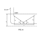
【解決手段】 本発明は、ハイドレート貯留層からメタンの回収を可能とする方法から成る。本発明は、特に、ハイドレート分解を起こさせて上方の傾斜生産井へのガス産出を促進および制御するため、高塩分水を下方の水平坑井に圧入してハイドレート貯留層に圧入するものである塩水ハイドレート抽出プロセス(SHEP)に関するものである。
【選択図】 図4The present invention comprises a method that enables the recovery of methane from a hydrate reservoir. In particular, the present invention injects high salinity water into the lower horizontal well and presses it into the hydrate reservoir in order to promote and control gas production to the upper inclined production well by causing hydrate decomposition. The salt hydrate extraction process (SHEP).
[Selection] Figure 4
Description
本発明はハイドレート貯留層からのガス回収の分野に関するものである。特に本方法は、水平平行坑井および非平行坑井および前記坑井の1つへの塩水の圧入を含む。 The present invention relates to the field of gas recovery from hydrate reservoirs. In particular, the method includes horizontal parallel and non-parallel wells and salt water injection into one of said wells.
ガスハイドレートは、氷の分子格子に封入されている分子メタン(CH4)を含む氷の結晶の形態である。メタンハイドレートは、標準状態でハイドレートの立方フィートごとに最大160立方フィートのガスを含む可能性がある。 Gas hydrate is a form of ice crystals containing molecular methane (CH 4 ) enclosed in an ice molecular lattice. Methane hydrate can contain up to 160 cubic feet of gas per cubic foot of hydrate under standard conditions.
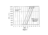
ハイドレートは加熱および減圧によりメタンガスおよび水を不安定化させることはよく知られている。ハイドレート相と平衡状態にある水の塩分の増加がまたハイドレートを不安定化することはあまり知られていない。図1は、圧力、温度、および塩分のメタンハイドレートエンベロープへの影響を示す。プロットは温度がより高いほど、圧力がより低いほど、塩分がより高いほど、ハイドレートの不安定化の可能性が高いことを示す。ハイドレートからのメタン産出のために提案される方法の大部分は、貯留層の加熱または減圧を用いる。しかしながら、これらは大量のエネルギーを消費する作業となる。所定の圧力および温度で、選択肢はハイドレートと平衡状態にある水相の塩分を上げることである。 It is well known that hydrate destabilizes methane gas and water by heating and decompression. Less is known that increasing the salinity of water in equilibrium with the hydrate phase also destabilizes the hydrate. FIG. 1 shows the effect of pressure, temperature, and salinity on the methane hydrate envelope. The plot shows that the higher the temperature, the lower the pressure, the higher the salinity, the higher the probability of hydrate destabilization. Most of the methods proposed for methane production from hydrate use reservoir heating or vacuum. However, these are operations that consume a large amount of energy. At a given pressure and temperature, the option is to increase the salinity of the aqueous phase in equilibrium with the hydrate.
ハイドレート抽出のための現在の方法は、水を圧入するためおよびガス産出のため垂直井の掘削する工程、水、温水および/または塩水を坑井へ圧入する工程を有し、ガスの放出の後、生産井からのガスの検索、および当技術分野で周知の方法によるその回収である。 Current methods for hydrate extraction have the steps of drilling a vertical well for injecting water and for gas production, injecting water, warm water and / or salt water into the well, and Later, retrieval of the gas from the production well and its recovery by methods well known in the art.
当技術分野で周知の圧入井および生産井のいくつかの配置がある。Matsuoによる米国特許第6,817,427号明細書には圧入パイプの周辺部を包囲する抽出パイプの記述がある。BacuiによるWO 2007/117167には、お互いに垂直および平行である坑井の記述がある。Ayoubによる米国特許第7,165,621号明細書には、垂直圧入井、さらには水平抽出井の記述がある。しかしながら、この特許はそのような配置の効果を議論していない。 There are several arrangements of injection and production wells that are well known in the art. U.S. Pat. No. 6,817,427 to Matsuo describes an extraction pipe that surrounds the periphery of a press-fit pipe. WO 2007/117167 by Bacui describes a well that is perpendicular and parallel to each other. U.S. Pat. No. 7,165,621 to Ayoub describes vertical injection wells and even horizontal extraction wells. However, this patent does not discuss the effect of such an arrangement.
すべてのこれらの配置は、1つ共通する欠陥を有する。すなわち、坑井の場所が埋蔵層からメタンの最適な抽出を提供しないということである。これらの配置は、坑井に近接した地下の割れ目およびポケットにたまるガスに対処するものではない。これらの配置は、埋蔵層の全ての層厚を通してガスの抽出に対処するものではない。ほぼ継続的に埋蔵層からメタンを回収するためにさらなる坑井を掘削する必要性がある。この方法は施設の建設費および運用コストを増大させる。 All these arrangements have one common defect. That is, the location of the well does not provide optimal extraction of methane from the reservoir. These arrangements do not deal with subsurface fissures and pockets of gas close to the well. These arrangements do not address gas extraction through the full thickness of the buried layer. There is a need to drill further wells to recover methane from the reserves almost continuously. This method increases the construction and operating costs of the facility.
したがって、ハイドレート層から回収の全プロセスを通してガスを効率的に抽出する方法が必要である。 Therefore, there is a need for a method of efficiently extracting gas from the hydrate layer through the entire recovery process.
最小限要求される掘削でガスを抽出する方法が必要である。 There is a need for a method of extracting gas with minimally required drilling.
各々のハイドレート層からハイドレートの回収を最大にするために空乏チャンバー(depletion chamber)の増大を促進するガス抽出のプロセスが必要である。 There is a need for a gas extraction process that facilitates an increase in the depletion chamber to maximize hydrate recovery from each hydrate layer.
ハイドレート層における水の塩分濃度を上昇させることが可能な新規の回収方法が開示されている。坑井の配置は、前記ハイドレート層において空乏チャンバーの増大を促進するように設計されている。圧入水の塩分の必要条件は、前記層において前記ハイドレートと平衡状態となる水の塩分濃度に依存する。水中塩分が海水の塩分濃度より低い場合、海水はハイドレートを分解するのに用いることが可能である。あるいは、他の層、例えば、より深い層からの高塩分水を用いることが可能である。 A novel recovery method capable of increasing the salt concentration of water in the hydrate layer is disclosed. The well arrangement is designed to promote an increase in the depletion chamber in the hydrate layer. The salinity requirement of the injected water depends on the salinity of the water in equilibrium with the hydrate in the layer. If the salinity in the water is lower than the salinity of seawater, the seawater can be used to decompose hydrate. Alternatively, high salinity water from other layers, such as deeper layers, can be used.
新規のin Situの貯留層回収方法は、図2で示すようにガスをハイドレート貯留層から抽出するための水平な圧入井と傾斜掘りした生産井とから成る。前記圧入井はハイドレート帯の底近くに配置される。前記坑井のつま先部の坑井間の距離間隔は約5〜10mである。この坑井の配置は、前記層内での空乏チャンバーの増大を促進および制御する。図6は、新規の方法の展開した様子を図示する。 The new in-situ reservoir recovery method consists of a horizontal injection well and a tilted production well for extracting gas from the hydrate reservoir as shown in FIG. The injection well is arranged near the bottom of the hydrate zone. The distance between wells in the toe portion of the well is about 5 to 10 m. This well arrangement facilitates and controls the growth of the depletion chamber within the layer. FIG. 6 illustrates the development of the new method.
高塩分水は、下方の坑井のつま先部に圧入されて前記層に圧入される。前記水の塩分濃度が増加している状態のため、一定の圧力および温度下において、ハイドレート相は分解されて水およびメタンが生成され、空乏地帯が形成される。水が貯留層の底部のより近位に留まるのに対し、ガスは前記空乏チャンバーは分離して最上部に留まる。その後、これらの流体は上方の生産井を用い前記空乏チャンバーから産出される。ガスは前記空乏チャンバーの上端に形成されるフリーガスキャップから産出されることも可能であり、またはガス−水接地点の下から産出される水に混入されているかもしれない。 High salinity water is pressed into the toes of the lower well and pressed into the layer. Due to the state in which the salinity of the water is increasing, the hydrate phase is decomposed to produce water and methane under a certain pressure and temperature, and a depletion zone is formed. Water stays closer to the bottom of the reservoir, while gas separates the depletion chamber and stays on top. These fluids are then produced from the depletion chamber using the upper production well. Gas can be produced from a free gas cap formed at the top of the depletion chamber, or it can be entrained in water produced from below the gas-water contact point.
ハイドレート分解から生じた淡水を生産井に移すのに十分な速度で高塩分水を圧入する。このように、空乏地帯の底部の水帯は圧入された高塩分水でほとんど充填され、空乏地帯の端部でハイドレート分解が継続的に行われる。ガスは、前記空乏チャンバーの底部での高塩分水の接触領域が最大になるように前記層でのガス量を制御する速度で空乏領域の最上部で産出される。生産井率はまた、前記一対の坑井に沿った前記空乏チャンバーの増大の制御を果たす。ガスは常に前記空乏チャンバーの最上部まで上昇し、ガス−水分離は重力安定性あるので、ガスの継続的な産出を可能にするためには、前記上方の生産井は前記ハイドレート貯留層の層厚を横断する必要がある。前記上方の生産井が水平である場合、ガスキャップが前記坑井の高さより上の位置に存在することにより、水のみが前記層から産出されるという可能性があった。ハイドレート分解は、ハイドレート貯留層の前記空乏チャンバーの端部の温度を低下させる。この温度低下は、塩水圧入によるハイドレート分解を妨げる。 High salinity water is injected at a rate sufficient to transfer fresh water from hydrate decomposition to the production well. Thus, the water zone at the bottom of the depletion zone is almost filled with the injected high salinity water, and hydrate decomposition is continuously performed at the end of the depletion zone. Gas is produced at the top of the depletion region at a rate that controls the amount of gas in the layer such that the contact area of high salinity water at the bottom of the depletion chamber is maximized. The production well rate also controls the growth of the depletion chamber along the pair of wells. Since gas always rises to the top of the depletion chamber and gas-water separation is gravity stable, the upper production well must be in the hydrate reservoir to allow continuous production of gas. It is necessary to cross the layer thickness. When the upper production well was horizontal, there was a possibility that only water would be produced from the layer due to the presence of a gas cap above the well height. Hydrate decomposition reduces the temperature at the end of the depletion chamber of the hydrate reservoir. This temperature drop prevents hydrate decomposition by salt water injection.
本発明の1実施形態では、圧入井および生産井が貫通された地下のハイドレート貯留層からメタンガスを回収する方法が提供される。その方法は、
a)前記ハイドレート貯留層の底に近接するまで塩水圧入井を掘削する工程と、
b)前記生産井を前記圧入井に対して実質的に非並行に、かつ前記生産井の長さにわたるある位置において前記圧入井の一部から1〜10m以内に位置するように掘削する工程と、
c)最初に前記生産井に塩水を圧入する工程であって、これにより前記圧入井と前記生産井との間に空乏チャンバーが形成されるものである、前記圧入する工程と、
d)ハイドレート層にハイドレート分解により生じる空乏チャンバーを拡大するために、前記塩水の圧入方法を変化させる工程であって、例えば望ましくは圧入圧、圧入率、温度、または塩分のうちの少なくとも1つを変化させる工程と、
e)前記生産井を通しての前記空乏チャンバーからのガスおよび水を抽出する工程とを有する。
In one embodiment of the present invention, a method for recovering methane gas from an underground hydrate reservoir through which a press-fit well and a production well are penetrated is provided. The method is
a) drilling a salt water injection well until close to the bottom of the hydrate reservoir;
b) excavating the production well so as to be located substantially non-parallel to the injection well and within 1 to 10 m from a portion of the injection well at a certain position over the length of the production well; ,
c) the step of initially injecting salt water into the production well, whereby a depletion chamber is formed between the injection well and the production well;
d) a step of changing the method of injecting the salt water in order to expand the depletion chamber generated by hydrate decomposition in the hydrate layer, for example, preferably at least one of press-in pressure, press-in rate, temperature, or salinity Changing the process,
e) extracting gas and water from the depletion chamber through the production well.
好ましくは、この方法はさらに、前記空乏チャンバーの拡大およびガスの抽出を向上させるために、前記圧入圧および温度を監視および変化させる工程を有する。前記方法はまた、前記空乏チャンバーの前記圧力および温度を変化させて、当該空乏チャンバーの拡大およびガスの抽出を行うために抽出率を監視および変化させる工程を有する。更に望ましくは、前記方法は、前記空乏チャンバーの拡大およびガスの抽出を向上させるために前記圧入水の塩分濃度を監視および変更する工程を有する。また、圧入が停止した状態でガスが貯留層から継続的に抽出される場合、追加の工程有することがあり得る。 Preferably, the method further comprises the step of monitoring and changing the press-fit pressure and temperature to improve the depletion chamber expansion and gas extraction. The method also includes the step of monitoring and changing the extraction rate to vary the pressure and temperature of the depletion chamber to expand the depletion chamber and extract gas. More preferably, the method includes monitoring and changing the salinity of the injected water to improve the expansion of the depletion chamber and gas extraction. Further, when gas is continuously extracted from the reservoir in a state where the press-fitting is stopped, an additional process may be included.
本発明の別の態様では、地下のハイドレート層からメタンガスを回収する方法が提供される。前記方法は、少なくとも一対の非平行な坑井である下方の圧入井と上方の生産井とを構築する工程を必要とする。前記圧入井は前記層に塩水を供給し、前記生産井は前記層からガスおよび水を回収する。この配置では、空乏チャンバーは前記一対の坑井の動作の結果として形成され、当該空乏チャンバーは前記坑井間が最小距離の地点から始まる。 In another aspect of the invention, a method for recovering methane gas from an underground hydrate layer is provided. The method requires constructing at least a pair of non-parallel wells, a lower injection well and an upper production well. The injection well supplies salt water to the bed, and the production well collects gas and water from the bed. In this arrangement, a depletion chamber is formed as a result of the operation of the pair of wells, and the depletion chamber begins at a point where the distance between the wells is the minimum.
好ましい実施形態において、前記圧入井は前記ハイドレート層の低部と近接して水平に延伸し、前記生産井は前記圧入井より上に延伸する。前記圧入井と前記生産井との間の垂直距離は、1〜10メートルの最小距離から前記ハイドレート層の層厚の最大距離の間で変化する。 In a preferred embodiment, the injection well extends horizontally close to the lower portion of the hydrate layer, and the production well extends above the injection well. The vertical distance between the injection well and the production well varies from a minimum distance of 1 to 10 meters to a maximum distance of the hydrate layer thickness.
好ましい1実施形態において、前記生産井のかかと部は前記ハイドレート層の最上部に近接して位置し、当該生産井のつま先部は前記圧入井のつま先部より1〜10メートル上に位置する。前記生産井は、そのかかと部とそのつま先部との間で前記圧入井に対してある角度をなして延伸する。 In a preferred embodiment, the heel part of the production well is located close to the top of the hydrate layer, and the toe part of the production well is located 1 to 10 meters above the toe part of the injection well. The production well extends at an angle with respect to the injection well between its heel part and its toe part.
第2の好ましい実施形態において、前記生産井のかかと部は、前記圧入井のかかと部の上1〜10メートルに位置し、当該生産井のつま先部はハイドレート層の最上部に近接して前記圧入井のつま先部より上に位置する。前記生産井は、そのかかと部とそのつま先部との間で前記圧入井に対してある角度をなして延伸する。 In a second preferred embodiment, the heel portion of the production well is located 1 to 10 meters above the heel portion of the injection well, and the toe portion of the production well is close to the top of the hydrate layer. Located above the toes of the injection well. The production well extends at an angle with respect to the injection well between its heel part and its toe part.
さらに別の実施形態において、前記生産井のかかと部は、前記圧入井のかかと部の上1メートルから前記ハイドレート層の最上部までの間の距離に位置しており、前記生産井のつま先部は、前記圧入井のつま先部の上1メートルから前記ハイドレート層の最上部までの間の選択された距離に位置する。前記生産井は、そのかかと部とそのつま先部との間で実質的に前記圧入井と非平行に延伸する。さらに、前記生産井のかかと部とつま先部との間の少なくとも1つの中間部分は、前記圧入井から1〜10メートルの距離に位置する。好ましくは、前記生産井と前記圧入井との間の角度は、前記坑井の先端部と前記坑井のつま先部との間で変化し、中間地点の前まではある角度をなし、当該中間地点を越えてからは別の角度をなすものである。 In yet another embodiment, the heel portion of the production well is located at a distance between 1 meter above the heel portion of the injection well and the top of the hydrate layer, and the toe portion of the production well Is located at a selected distance between 1 meter above the toe of the injection well and the top of the hydrate layer. The production well extends substantially non-parallel to the injection well between its heel part and its toe part. Furthermore, at least one intermediate part between the heel part and the toe part of the production well is located at a distance of 1 to 10 meters from the injection well. Preferably, the angle between the production well and the injection well varies between the tip of the well and the toe of the well, and forms an angle before the intermediate point, the intermediate After crossing a point, it makes another angle.
本発明のさらに別の態様では、上述の方法はまた、加熱した塩水を前記圧入井に圧入して、前記産出されるガスおよび水を前記生産井から回収する工程を有する。 In yet another aspect of the present invention, the method also includes the step of injecting heated brine into the injection well and recovering the produced gas and water from the production well.
望ましくは、上述の方法のうちの1つの工程において、前記生産井の排出口は閉鎖されて前記圧入井のみが運用可能であり、さらに別の工程において、前記圧入井の注入口は閉鎖されて前記生産井のみが運用可能である。 Preferably, in one of the above-described methods, the production well outlet is closed and only the injection well is operational, and in yet another step, the injection well inlet is closed. Only the production well can be operated.
本発明のさらに別の態様では、ハイドレート層からメタンガスを抽出する方法が提供される。この方法は、
a)2つの非平行な坑井である下方の圧入井と上方の生産井とを掘削する工程と、
b)空乏チャンバーを生成するため、前記下方の坑井に加熱した塩水を圧入する工程と、
c)気相および水相に分離されるのを待つ工程と、
d)埋蔵層から前記気相および水相を抽出する工程と、
e)前記水相から前記気相を分離する工程と、
f)前記水相を再利用して圧入に使用する工程とを有する。
In yet another aspect of the invention, a method for extracting methane gas from a hydrate layer is provided. This method
a) drilling two lower parallel wells, a lower injection well and an upper production well;
b) injecting heated salt water into the lower well to produce a depletion chamber;
c) waiting to be separated into a gas phase and an aqueous phase;
d) extracting the gas phase and aqueous phase from the buried layer;
e) separating the gas phase from the aqueous phase;
f) reusing the water phase and using it for press-fitting.
好ましくは、この方法は、前記ハイドレート層の底部で実質的に水平に延伸する前記下方の坑井と、前記下方の坑井にある角度をなして延伸する前記上方の坑井とを有する。前記坑井間の垂直距離は1メートルから前記ハイドレート層の最上部までの距離で変化するものであり、このような方法で、ガスは前記空乏チャンバーの任意の場所から抽出されることが可能である。 Preferably, the method comprises the lower well extending substantially horizontally at the bottom of the hydrate layer and the upper well extending at an angle to the lower well. The vertical distance between the wells varies from 1 meter to the top of the hydrate layer, and in this way gas can be extracted from any location in the depletion chamber It is.
本発明の別の態様では、ハイドレート層からメタンガスを抽出するシステムを提供するものであり、そのシステムは、圧入井と、生産井と、水圧入ユニットと、ガス回収ユニットとを有する。前記圧入井は前記ハイドレート層の底部に向かって圧入地点から垂直に延伸し、その後前記ハイドレート層の底部に沿って水平に延伸する。前記生産井は地面から前記ハイドレート層の最上部まで垂直に延伸し、その後前記圧入井より上で非平行な方向で延伸する。さらに、前記生産井の少なくとも一部分は前記圧入井に近接して配置され、前記生産井の残りの部分は前記ハイドレート層で前記圧入井から離れて配置されている。最後に、前記水圧入ユニットは前記圧入井に取り付けられ、前記ガス回収ユニットは前記生産井に取り付けられる。 In another aspect of the present invention, a system for extracting methane gas from a hydrate layer is provided, and the system includes a press-fit well, a production well, a water press-fit unit, and a gas recovery unit. The injection well extends vertically from the injection point toward the bottom of the hydrate layer, and then extends horizontally along the bottom of the hydrate layer. The production well extends vertically from the ground to the top of the hydrate layer and then extends in a non-parallel direction above the injection well. Furthermore, at least a part of the production well is disposed close to the injection well, and the remaining part of the production well is disposed away from the injection well in the hydrate layer. Finally, the water injection unit is attached to the injection well, and the gas recovery unit is attached to the production well.
好ましくは、上述のシステムまたは方法において、さらに、可動式パッカーを前記生産井に有する。 Preferably, in the above-described system or method, the production well further has a movable packer.
本明細書において記述される方法はまた、ハイドレートを分解するのに必要とされる温度を相殺するのに必要とされる温度に対応するために貯留層温度より約+5℃上まで加熱した塩水を圧入することが可能である。 The method described herein also includes brine heated to about + 5 ° C. above the reservoir temperature to accommodate the temperature required to offset the temperature required to decompose the hydrate. Can be press-fitted.
坑井の配置の1つの長所は、追加の外れた生産井が、現存の一対の坑井のかかと部およびつま先部、および前記既存の一対の前記下方の圧入井を越えて掘削が可能であり、かつ新規の生産井を供給するのに使用可能である場合、ハイドレートの広領域産出を促進することである。 One advantage of well placement is that additional off-site production wells can be drilled across the heel and toe of an existing pair of wells and the existing pair of lower injection wells. And, if it can be used to supply new production wells, to promote the wide area production of hydrate.
この優れた配置の別の長所は、薄いハイドレート層および厚いハイドレート層の両方に対応することである。 Another advantage of this superior arrangement is that it accommodates both thin and thick hydrate layers.
本方法の別の長所は、高塩分圧入水を前記ハイドレートのさらなる分解を促進するために加熱することが可能なことである。 Another advantage of the method is that the high salinity water can be heated to promote further decomposition of the hydrate.
本方法の別の長所は、当該方法を周期的に運用することが可能なことである。この方法では、前記生産井が閉鎖された状態で前記層に前記高塩分水が圧入される。高塩分水の目的圧力または量が圧入された後、前記圧入井は閉鎖され、前記生産井が開かれる。前記高塩分水を加える産出の作用は、ハイドレートの分解と、ハイドレート分解およびガス産出を向上させる一時的圧力とを含む複数の効果を生む。 Another advantage of the method is that it can be operated periodically. In this method, the high salinity water is injected into the layer with the production well closed. After the target pressure or amount of high salinity water is injected, the injection well is closed and the production well is opened. The production action of adding high salinity water produces multiple effects including hydrate decomposition and temporary pressure to improve hydrate decomposition and gas production.
他の1つの長所は、産出ガスは産出された流体の流れから容易に分離されることである。また、産出された水は有する塩分が圧入水より少ないため、後で廃棄が容易にできる。 Another advantage is that the produced gas is easily separated from the produced fluid stream. Further, since the produced water has less salt than the injected water, it can be easily discarded later.
他の1つの長所は、空乏チャンバーにおける二酸化炭素の溶解トラップ(solubility trapping)のため、二酸化炭素を水と共に同時圧入することも可能なことである。 Another advantage is that carbon dioxide can be co-injected with water due to the solubility trapping of carbon dioxide in the depletion chamber.
この坑井の配置の他の1つの長所は、前記一対の坑井に沿った空乏の増大を制御するため、可動式パッカーまたは間隔制御弁を前記坑井の一方または両方で用いることが可能なことである。 Another advantage of this well arrangement is that movable packers or spacing control valves can be used on one or both of the wells to control the increase in depletion along the pair of wells. That is.
さらなる長所は、提供された図面、実施例、および請求項から明らかである。 Further advantages are apparent from the drawings, examples, and claims provided.
当技術分野で周知のプロセスの欠陥のいくつかは、本発明において対処される。 Some of the process defects known in the art are addressed in the present invention.
第1に、このプロセスは、結果的に地下の割れ目にガスの損失をもたらす埋蔵層の割裂および表面に浸出しているポケットの割裂の危険性を除外する。 First, this process eliminates the risk of cracking of buried layers and cracking of pockets leaching to the surface, resulting in gas loss in underground fissures.
第2に、ハイドレート回収プロセスは、ハイドレートを分解するだけでなく、生産されたガスを生産井に送達する手段も提供する必要がある。これは、前記回収プロセスが貯留層の中で前記ガスを分離する必要があり、前記貯留層の前記ガスと前記生産井との間の直接の流体接続部を提供する必要があることを意味する。前記生産井が前記貯留層の全層およびかなりの設置面積領域に及ぶため、本プロセスはこれを保証する。垂直井を用いるプロセスは、広大な設置面積領域および水平坑井の高度までのみに接続する水平坑井を用いるプロセスを有しない(前記水平坑井上に位置するガスポケットは表面に決して生産されることが不可能である)。 Second, the hydrate recovery process needs to not only decompose the hydrate, but also provide a means to deliver the produced gas to the production well. This means that the recovery process needs to separate the gas in a reservoir and provide a direct fluid connection between the gas in the reservoir and the production well. . The process guarantees this because the production well spans the entire reservoir and a substantial footprint area. The process using vertical wells does not have the process of using horizontal wells that connect only to the vast footprint area and to the height of the horizontal wells (gas pockets located on the horizontal wells are never produced on the surface Is impossible).
さらに、ハイドレート回収プロセスは、継続的に前記貯留層に分解「作用因子」(熱、塩水、減圧)を供給する手段を提供する必要がある。本プロセスは、温塩水を循環させることでチャンバーを増大させることによりこれを行う。このように、塩および熱が継続的に補充され、分解が原因で、希釈された塩水は継続的に空乏チャンバーから除去され、圧入した前記温塩水と置換される。割裂底部の回収プロセスでは、割裂が生じた後、分解作用因子が割裂に継続的に供給されない限り、前記空乏チャンバーは増大しない。 Furthermore, the hydrate recovery process needs to provide a means to continuously supply the decomposition “acting factors” (heat, salt water, reduced pressure) to the reservoir. The process does this by increasing the chamber by circulating hot brine. In this way, salt and heat are continuously replenished, and due to decomposition, the diluted brine is continuously removed from the depletion chamber and replaced with the hot brine injected. In the split bottom recovery process, after the split occurs, the depletion chamber does not increase unless a degradation agent is continuously supplied to the split.
図を参照して、上方の傾斜生産井へのハイドレート分解によるガス産出を促進し、制御するために、下方の水平坑井に、そしてハイドレート貯留層に、高塩分水を圧入する塩水ハイドレート抽出プロセス(SHEP)の解説がなされる。概して、本発明は、前記ハイドレート貯留層から結果的に有意に改善されたメタンガス産出をもたらす新規の坑井の配置および新規の圧入戦略から成る。 Referring to the figure, a saltwater hydride that injects high salinity water into the lower horizontal well and into the hydrate reservoir to promote and control gas production by hydrate cracking into the upper inclined production well. The rate extraction process (SHEP) is explained. In general, the present invention consists of a new well arrangement and a new injection strategy that results in significantly improved methane gas production from the hydrate reservoir.
ハイドレートは、in situの最初の貯留層温度および圧力において固形物である。高温または減圧で、ハイドレートは分解し、液体の水およびメタンガスを産出する。また、高塩分状態で、ハイドレートは分解し、液体の水およびメタンガスを産出する。ハイドレート回収プロセスの成功の第1の必要条件は、以下の状態のうち、1若しくはそれ以上貯留層に存在する必要があるということである。第1に、熱水または水蒸気のような熱い圧入物質の形態であることが可能な加熱。第2に、貯留層から流体を除去することにより行うことが可能である減圧。第3に、例えば、ハイドレート貯留層に高塩分水を圧入することまたは当技術分野で周知の任意の方法により認識することが可能である塩分濃度の増加。 Hydrate is a solid at the initial reservoir temperature and pressure in situ. At high temperature or reduced pressure, the hydrate decomposes to produce liquid water and methane gas. In a high salinity state, the hydrate decomposes to produce liquid water and methane gas. The first requirement for the success of the hydrate recovery process is that it must be present in one or more reservoirs of the following states. First, heating that can be in the form of a hot press material such as hot water or steam. Second, decompression that can be performed by removing fluid from the reservoir. Third, an increase in salinity that can be recognized, for example, by injecting high salinity water into a hydrate reservoir or by any method known in the art.
ハイドレート回収プロセスの成功の第2の必要条件は、ハイドレート分解により発生するガスを地表に運ぶため、生産井に供給する必要かあるということである。前記ハイドレートが分解する時、液体と水は重力の働きの下で分離し、ガスは空乏チャンバーの最上部まで上昇するのに対して、液体は前記空乏チャンバーの底へ降下する。ガスを生産するために、それが水帯に存在する場合、前記生産井はガス帯と接触したままである必要があり、さもなければその後、水のみが貯留層から産出される。このように、ハイドレート回収プロセスの成功の坑井の配置は、熱または塩水の圧入、またはより低圧への流体の除去、またはそれらすべての組合せをさせ、さらに生産井へガスの移動をさせる必要がある。 A second requirement for the success of the hydrate recovery process is that the gas generated by the hydrate decomposition needs to be supplied to the production well in order to carry it to the surface. As the hydrate breaks down, liquid and water separate under the action of gravity and gas rises to the top of the depletion chamber, while liquid falls to the bottom of the depletion chamber. In order to produce gas, if it is in a water zone, the production well needs to remain in contact with the gas zone, otherwise only water is produced from the reservoir. Thus, the successful well arrangement of the hydrate recovery process requires the injection of heat or brine, or the removal of fluid to a lower pressure, or a combination of all, and further transfer of gas to the production well. There is.
ここに、記述される方法は、ハイドレートを分解する時必要とされる溶解の熱を埋め合わせするために温めた塩水圧入を用いる可能性がある。空乏チャンバーがハイドレート貯留層で増大するため、それは圧入水およびハイドレート分解した水およびハイドレート生成したガスを分離する天然の手段を提供し、その手段とは、重力の働きの下で、蒸気と液体との間の密度対比により相を分離させるものである。継続的にガスを貯留層から作り出すために、それはまた、圧入した塩水が新たなハイドレートに接近するのを確実とするため、前記空乏チャンバーを拡大することが要求される。 The method described here may use warm brine injection to compensate for the heat of dissolution required when breaking down the hydrate. As the depletion chamber grows in the hydrate reservoir, it provides a natural means of separating the injected and hydrate-decomposed water and hydrate-generated gas, which means that under the action of gravity, steam The phases are separated by density contrast between the liquid and the liquid. In order to continually create gas from the reservoir, it is also required to expand the depletion chamber to ensure that the injected brine is approaching the new hydrate.
本発明の別の重要な部分は、坑井の方向、埋蔵層の坑井の位置、およびお互いのそれらの相対的な位置である。少なくとも1つの圧入井および少なくとも1つの生産井がある。生産井は、ハイドレートから放出されるガスを回収するために圧入井より上に位置する。前記生産井はまたチャンバーから水を除去するために用いられる。かかと部からつま先部までの生産地帯(坑井の足部位)において、坑井が互いに実質的に非平行または少なくとも坑井の部分のいくつかに沿って非平行であるが、前記坑井は地表から前記坑井のかかと部までの部分(坑井の脚部位)において平行である可能性がある。前記坑井は、埋蔵層の特定限界について対処するために、直線、角度のある線、および可変的な角度を持つ線で掘削される可能がある。その生産地帯(坑井の足部位)における圧入井が実質的に水平に延伸し、埋蔵層の底に向かい位置するが、生産井は、その生産地帯において前記圧入井に対し角度を持ち、この角度は前記生産井の拡張に従い数倍異なる可能性がある。 Another important part of the present invention is the direction of the wells, the position of the wells in the reservoir and their relative position with respect to each other. There is at least one injection well and at least one production well. The production well is located above the injection well to recover the gas released from the hydrate. The production well is also used to remove water from the chamber. In the production zone from heel to toe (well foot), the wells are substantially non-parallel to each other, or at least non-parallel along some of the portions of the well, but the well is To the heel of the well (the well leg portion) may be parallel. The wells can be drilled with straight lines, angled lines, and lines with variable angles to address specific limitations of the buried layer. The injection well in the production zone (the well part of the well) extends substantially horizontally and faces the bottom of the buried layer, but the production well has an angle with respect to the injection well in the production zone. The angle may vary several times according to the expansion of the production well.
本発明に従い、図2および7で示すように、水平圧入井5は、陸地1および表土2の表面を貫通し、ハイドレート貯留層3に掘削される。貯留層は、表土2の底および基盤岩4の最上部により境界される。地熱勾配を与えられる基盤岩4は、水の豊富な地帯から成る。前記貯留層3より上は、頁岩、岩、砂層、および帯水層のような他の層の任意の1若しくはそれ以上から成る表土2である。そのつま先部が生産井5のつま先部との垂直整列において1〜数メートル上に配置されるよう掘削した傾斜掘り坑井はまた、前記貯留層3に掘削される。本発明では、図8で示すように、塩水を前記ハイドレート貯蔵層3へ圧入井5を通して圧入し、前記圧入井5から前記圧入井5を囲む空乏チャンバー7へ流す。前記貯留層3に温塩水を圧入することにより、塩水および熱を前記貯留層3に伝え、最終的に空乏チャンバー7の端に至り、前記貯留層3において最初のハイドレートに接触する。塩水は、固体ハイドレートを分解し、液体水およびメタンガスの産出の原因となる。ガスは上昇し、前記空乏チャンバーの上部を図5の8で示すように満たすが、水は重力を受け流れ、前記空乏チャンバーの下部を図5の9で示すように満たす。生産井6の撤退率を、前記空乏チャンバーから地表1へ液体の水およびガス両方を除去するために制御する。この率はハイドレート分解で発生する水により圧入された塩水の過度の希釈を妨げる値に設定される。また、圧入された塩水が増大する空乏チャンバーの最上部に接触することが可能なように、前記空乏チャンバーにおける生産率を、図5の8で示す蒸気相体積が小さいまたはほぼ0となるように、調整する必要がある。図9は、空乏チャンバー9の拡大の後、その生産の後半段階におけるプロセスの概略図を示す。前記空乏チャンバーの増大の工程は、図6に図示される。
According to the present invention, as shown in FIGS. 2 and 7, the horizontal injection well 5 penetrates the surface of the
図2において最も良く図示される本発明の第1の実施形態において、それがハイドレート貯留層の層厚全体に広がり、さらにそのつま先部は圧入井のつま先部に近接するように、傾斜掘りされる生産井6の軌道は選択される。坑井の寸法は、埋蔵層の地質条件、前記埋蔵層のサイズ、深さ、その他に依存する。一般的な寸法は下記の通りである。h1は前記圧入井のつま先部と生産井のつま先部との間の鉛直変位である。距離h1は、0.5〜10m、望ましくは1〜5mである。項目h2は、当技術分野で周知の方法で測定することが可能な(貯留層の底から圧入井の補正値を差し引いた)ハイドレート貯留層の層厚である。圧入井はかかと部からつま先部まで実質的に水平に延伸し、その距離(L)は50〜1500m、望ましくは100〜1000mである。θは、前記生産井と前記圧入井のと間の角度である。この角度は、0.5〜45°、望ましくは1〜10°である。項目hは前記ハイドレート貯留層の層厚である。この層厚は非常に多様性がある可能性があり、通常20〜200mで延伸する。
In the first embodiment of the invention best illustrated in FIG. 2, it is tilted so that it spans the entire thickness of the hydrate reservoir, and its toes are close to the toes of the injection well. The trajectory of the
図3に図示される本発明の第2の実施形態において、生産井は、ハイドレート層の地質条件に対処するために、異なる方向性を有する。そこで、圧入井と前記生産井との間の最小の距離h1は、両坑井のかかと部であり、2つとの間の距離は前記両坑井のつま先部h2に向かい増加する。h2は貯留層の層厚とほぼ等しいが、「h1」は0.5〜10m、望ましくは1〜5mである。角度θは、再び0.5〜45°、望ましくは1〜10°である。 In the second embodiment of the present invention illustrated in FIG. 3, the production wells have different orientations to address the geological conditions of the hydrate layer. Therefore, the minimum distance h 1 between the production well and injection well is a heel portion of Ryoanai, the distance between the two and is increased toward the toe portion h 2 of the two wells. h 2 is approximately equal to the thickness of the reservoir layer, "h 1" is 0.5 to 10 m, desirably 1 to 5 m. The angle θ is again 0.5 to 45 °, preferably 1 to 10 °.
本技術の1つの目的は、坑井間の距離(h1)が比較的短く(1〜10m、望ましくは1〜5m)、その後坑井の軌線に沿う坑井に沿った地点から始まる空乏チャンバーを増大させることであるため、好ましい実施形態において、坑井の形状にはいくつかの実行可能な選択肢がある。さらに、注記しておかなくてはいけないことは、一対の坑井軌道が垂直平面にある必要がないことである。それは横方向に(水平方向で)互いから分岐することが可能であり、従って貯留層において横方向に延伸する空乏チャンバーを形成する。 One objective of this technique is a depletion that begins at a point along the well along the well trajectory, after the distance (h 1 ) between wells is relatively short (1-10 m, preferably 1-5 m). Due to the increased chamber, in the preferred embodiment, there are several possible options for the well shape. Furthermore, it should be noted that the pair of well tracks need not be in a vertical plane. It can branch off from each other laterally (in the horizontal direction), thus forming a depletion chamber that extends laterally in the reservoir.
本発明のさらに別の実施形態において、空乏チャンバーの起点となる一対の坑井に沿った地点は、図3で示すようにかかと部または坑井の図1で示すようなつま先部である必要はないが、例えば図4および図5で示されるように、それは一対の坑井に沿った任意の点にある可能性がある。これらの図は、非平行および部分的に平行である一対の坑井の形状のさらなる実施形態を図示するものである。距離h、h1、h2は上述の第1の実施形態と同じ範囲にあり、傾斜度θ1、θ2はθの値と同じ範囲にあるが、h3の範囲はh2と類似する。図5におけるL1の水平部分は、20〜1200m、望ましくは20〜100mである。 In yet another embodiment of the invention, the point along the pair of wells from which the depletion chamber originates must be a heel or a toe as shown in FIG. 1 of the well. Although not, for example, as shown in FIGS. 4 and 5, it may be at any point along a pair of wells. These figures illustrate a further embodiment of a pair of well shapes that are non-parallel and partially parallel. Distance h, h 1, h 2 are in the same range as the first embodiment described above, inclination theta 1, theta 2 is in the same range as the value of theta, the range of h 3 is similar to h 2 . Horizontal portion of the L 1 in FIG. 5, 20~1200m, desirably 20 to 100 m.
本発明のさらに別の実施形態において、チュービングストリングは、坑井(図4の第3の実施形態の坑井)のつま先部で終わる生産井に設置される可能性がある。このチュービングの配置は、同時にかかと部および前記つま先部から流体を除去することが可能であり、従って潜在的にプロセスをより効率的にする(1つよりも2つの除去ポイント)。チャンバーは、(h1)の位置(図4を参照)から、一対の坑井に沿って両方向で外側へ増大する。コイル状のチュービングストリングは、標準的な坑井技術である。さらに、可動式パッカーは、チャンバーの増大を導くために前記生産井に設置することが可能である。 In yet another embodiment of the present invention, the tubing string may be installed in a production well that terminates at the toe portion of the well (third embodiment of the well of FIG. 4). This tubing arrangement can simultaneously remove fluid from the heel and the toes, thus potentially making the process more efficient (two removal points than one). The chamber increases outward from the position (h 1 ) (see FIG. 4) in both directions along a pair of wells. Coiled tubing strings are standard well technology. Furthermore, a movable packer can be installed in the production well to guide the increase in chamber.
図7において、800mの長の一対の坑井の塩水およびメタンガスの典型的な圧入および生産プロファイルを示す。これらのプロファイルは、ハイドレート層および分解対圧力の熱力学、温度、および塩分が考慮される業務用の熱貯留層シミュレーターCMG−STARを用いてシミュレーションされた。図11は、前記シミュレーションに用いた坑井の配置を示す。底部の坑井が圧入井であるのに対し、最上部の坑井は生産井である。 In FIG. 7, a typical intrusion and production profile of salt water and methane gas for a pair of 800m long wells is shown. These profiles were simulated using a commercial thermal reservoir simulator CMG-STAR that takes into account the hydrate layer and decomposition versus pressure thermodynamics, temperature, and salinity. FIG. 11 shows the arrangement of wells used in the simulation. The bottom well is an injection well, while the top well is a production well.
プロセスの初期は、坑井との間で加熱を促進するために熱水を圧入井5および生産井6において循環させる可能性がある。最も近い坑井間の間隔は坑井のつま先部であり、よって、坑井のつま先部の領域が坑井との間で最も温められる。この加熱は、そこで空乏チャンバーの起点を開始する坑井のつま先部との間で、ハイドレートの分解を引き起こす。前記空乏チャンバーが形成されると、塩水が前記圧入井5に圧入され、前記空乏チャンバーを満たす。一旦塩水と接触すると、チャンバーの端でハイドレートは分解し、図8で示すように前記チャンバーの体積を拡大させる。 Early in the process, hot water may be circulated in the injection well 5 and production well 6 to facilitate heating to and from the well. The distance between the nearest wells is the toe part of the well, so that the area of the toe part of the well is most warmed with the well. This heating causes the hydrate to decompose between the well toes and where the depletion chamber begins. When the depletion chamber is formed, salt water is injected into the injection well 5 to fill the depletion chamber. Once in contact with salt water, the hydrate decomposes at the end of the chamber, increasing the volume of the chamber as shown in FIG.
ハイドレートを溶解させるために必要な熱を埋め合わせするために、圧入された塩水はチャンバー温度より数度上、望ましくは+5℃またはそれ以下で加熱される可能性がある。塩水の圧入率および水の生産率は、生産井6に気体運動を刺激し、空乏チャンバーの最上部でほとんどまたは全くガスがないように維持すべく、高く維持する。しかしながら、圧力は最初の貯留層圧以下で前記空乏チャンバーで維持される。これは、ハイドレート分解がハイドレート貯留層で圧力の増加により阻害されないことを保証するものである。最初の貯留層圧の圧力より低い圧力で前記空乏チャンバーを運用することで前記ハイドレート分解を促進し、システムのガス生成率が向上する。
In order to make up for the heat required to dissolve the hydrate, the injected brine can be heated several degrees above the chamber temperature, desirably + 5 ° C. or below. The salt water injection rate and water production rate are kept high to stimulate gas motion in the
プロセスが展開し、チャンバーはハイドレート貯留層の最上部に達し、その後圧入井/生産井の対から外側へ横方向に広がる。前記プロセスは、前記ハイドレート貯留層において目標とした空乏チャンバー増大計画を達成するために調整される現場において、いくつかの対の前記圧入井および前記生産井で運用することが可能である。 As the process develops, the chamber reaches the top of the hydrate reservoir and then extends laterally outward from the injection / production well pair. The process can be operated with several pairs of injection wells and production wells at a site that is coordinated to achieve a targeted depletion chamber expansion plan in the hydrate reservoir.
ハイドレートの分解が最大となるように、圧入する塩水および産出する水の量および圧入圧が選択される。 The amount of salt water to be injected and the amount of water produced and the injection pressure are selected so as to maximize the decomposition of the hydrate.
チャンバー7が増大し、図9で示されるように、より冷えた状態の表土と比較し、加熱した水蒸気チャンバー7がより広範囲の露出領域を持つため、表土2への熱損失は増加する。しかしながら、薄いガスブランケット8は、生産井6の穿孔より上に、空乏チャンバー7の最上部で維持される。このガスブランケットは、熱水帯を冷えた表土から隔離し、それ故にプロセスの熱効率を上昇さる。
As the
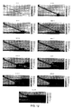
図12は、CMG−STARSを用いて作成したシミュレーションの結果を表す。コンピューターモデリンググループ社(CMG社)により提供されたソフトウェアSTARS=熱の貯留層シミュレーター。この第三者プログラムは、油およびガス(従来型および非従来型)貯留層回収プロセスの熱および反応シミュレーションのための業界標準である。したがって、前記シミュレーションの結果は、実際のプロセスの現実的な予測として考えることが可能である。図12は、プロセスを時間0から10年目まで展開する場合の通し時間のハイドレート濃度、gmole/m3、の11年間の時系列を示す。空乏した地帯は、塩水圧入が持続的となるような、坑井間の距離間隔が最も小さい場所で始まり、その後一対の坑井に沿って増大する。空乏チャンバーは、生産井に沿って、それより上に増大する。
FIG. 12 shows the result of a simulation created using CMG-STARS. Software STARS = thermal reservoir simulator provided by Computer Modeling Group (CMG). This third party program is an industry standard for thermal and reaction simulation of oil and gas (conventional and unconventional) reservoir recovery processes. Therefore, the result of the simulation can be considered as a realistic prediction of an actual process. FIG. 12 shows an 11-year time series of hydrate concentrations over time, gmole / m 3 , when the process is deployed from
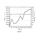
図13は、(最初の貯留層温度より5℃上の)温塩水圧入下でのガス産出と、(最初の貯留層温度より5℃上の)温淡水の圧入での結果との比較を示す。結果は、温塩水圧入による生産率が温淡水によるそれより大幅に高いことを示す。(メタン燃焼により)水を加熱するためのコストを考えると、圧入する塩水の加熱は、可能な限り少なく保つ必要がある。 FIG. 13 shows a comparison of gas production under hot brine injection (5 ° C. above the initial reservoir temperature) and results from hot fresh water injection (5 ° C. above the initial reservoir temperature). . The results show that the production rate by hot salt water injection is significantly higher than that by hot fresh water. Given the cost of heating the water (by methane combustion), the salt water that is injected must be kept as low as possible.
ガス回収施設の運用中に、貯留層で形成されるいくつかの地帯がある。ハイドレート貯留層の底で、つくられる「移行」地帯があり、それは水、ハイドレート、および沈殿物を含む。圧入井は前記ハイドレート貯留層の底に位置する可能性があり、また最終的に、それは移行地帯に設置されることが可能である。 There are several zones formed by reservoirs during the operation of gas recovery facilities. At the bottom of the hydrate reservoir, there is a “transition” zone created, which contains water, hydrate, and sediment. The injection well can be located at the bottom of the hydrate reservoir, and ultimately it can be installed in the transition zone.
水の圧入率は、プロセスの段階に依存し、回収プロセスの間に貯蔵層のサイズおよび状態を変化させる。(温塩水の)圧入率の場合、運用の範囲は1〜2000m3/日であるが、それはまた貯留層の「圧入性」(圧入率貯留層が順応する)により制御される。圧入圧は、前記貯留層の割裂圧より下である必要がある。それがまだガスの経済的生産を生み出す間、好ましい範囲は可能な限り低い。 The water injection rate depends on the stage of the process and changes the size and condition of the reservoir during the recovery process. In the case of the injection rate (warm salt water), the range of operation is 1 to 2000 m 3 / day, but it is also controlled by the “pressability” of the reservoir (the injection rate reservoir adapts). The press-fitting pressure needs to be lower than the splitting pressure of the reservoir. The preferred range is as low as possible while it still produces economic production of gas.
圧入された塩水の温度は、生産されたハイドレートを溶解する熱を埋め合わせするのに十分である必要がある。このように、塩水の温度は、経済的にプロセスを効率的にするために可能な限り低くなければならないが、プロセスを効果的にするために溶解の熱を埋め合わせするのに十分高い必要がある。水の温度の運用範囲は、ハイドレート貯留層の最初の温度より1〜20℃上である。しかしながら特殊な場合においては、その温度は、ハイドレート貯留層の最初の温度より40℃上と同じ程度高い可能性がある。 The temperature of the injected brine must be sufficient to compensate for the heat that dissolves the hydrate produced. Thus, the temperature of salt water must be as low as possible to make the process economically efficient, but it must be high enough to make up the heat of dissolution to make the process effective. . The operating range of water temperature is 1-20 ° C. above the initial temperature of the hydrate reservoir. However, in special cases, the temperature can be as high as 40 ° C. above the initial temperature of the hydrate reservoir.
圧入圧は、運用の様々な段階の間、変更する可能性がある。貯留層の割裂圧より下の圧力は通常の運用の期間は好まれるが、初期状態では、プロセスを開始することが可能となるように、この圧力は最初のハイドレート貯留層圧より高くなる可能性がある。空乏チャンバーが形成されるとすぐに、その後減圧によりハイドレートからのガス回収を増加させるために、圧入圧を貯留層の最初の圧力より下に下げることが可能である。 The press-fit pressure may change during various stages of operation. A pressure below the splitting pressure of the reservoir is preferred during normal operation, but in the initial state this pressure can be higher than the initial hydrate reservoir pressure so that the process can be started. There is sex. As soon as the depletion chamber is formed, the press-fit pressure can be lowered below the initial pressure of the reservoir in order to increase gas recovery from the hydrate by subsequent depressurization.
圧力の時系列は、以下の通りである。 The time series of pressure is as follows.
プロセスの開始時(最初の1〜12ヵ月)
最初の貯留層圧<圧入圧<割裂圧
空乏チャンバーを形成した後(3〜24ヵ月)、圧入圧は最初の貯留層圧の上または下である可能性があるが、最適状態は以下の通りである。
At the start of the process (first 1-12 months)
Initial reservoir pressure <injection pressure <splitting pressure After forming the depletion chamber (3-24 months), the injection pressure may be above or below the initial reservoir pressure, but the optimal conditions are as follows: It is.
圧入圧<最初の貯留層圧
上記で提供した運用のタイミングはおおまかなもので、貯留層の特定の性質に依存するが、それらのタイミングは合理的なものである。
Intrusion Pressure <Initial Reservoir Pressure The operational timing provided above is approximate and depends on the specific nature of the reservoir, but those timings are reasonable.
さらに他の好ましい実施形態において、ガス抽出方法は、周期的方法で運用されることが可能である。この方法では、生産井を閉鎖し、高塩分水を層に圧入する。高塩分水の目標圧または体積を達成した後、圧入井は閉鎖され、前記生産井が開けられる。生産の変化に従う高塩分水の作用は、ハイドレートの分解、さらにはハイドレート分解およびガス産出を向上させる一時的な圧力を含む複数の影響の原因となる。 In yet another preferred embodiment, the gas extraction method can be operated in a periodic manner. In this method, the production well is closed and high salinity water is injected into the bed. After achieving the target pressure or volume of high salinity water, the injection well is closed and the production well is opened. The action of high salinity water following production changes causes multiple effects including hydrate decomposition, and even temporary pressures that improve hydrate decomposition and gas production.
本発明の方法は貯留層の深さに依存しないが、深さは塩水圧入のための圧力に影響を及ぼす。また、ハイドレート層の最初の圧力および温度は、必要とされる塩の量および圧入された塩水の加熱の量に影響する。上述の方法は、ハイドレート貯留層の状態に合わせる必要がある。 Although the method of the present invention does not depend on the depth of the reservoir, the depth affects the pressure for salt water injection. Also, the initial pressure and temperature of the hydrate layer affects the amount of salt required and the amount of heating of the injected salt water. The method described above needs to be matched to the state of the hydrate reservoir.
本発明のプロセスでは、ハイドレート層の割裂はない。前記プロセスは、層を割裂(ひびを入れ壊す)させるのに十分な圧力で、流体の貯留層への圧入を必要としない。割裂は、ハイドレート回収プロセスにとり潜在的に不都合なものである。層を割裂すことにより、高い透過性経路が層において形成され、それが生産井に接続していない場合、分解したハイドレートから水を吸い取る地層、水喰土に生じたガスは潜在的に漏出する。例えば、垂直割裂が起こる場合、その後ハイドレートから作られるガスは潜在的に割裂にそり上昇し表土に(生産井を越えて行き)流出する。 There is no splitting of the hydrate layer in the process of the present invention. The process is at a pressure sufficient to split (break) the layer and does not require the injection of fluid into the reservoir. Splitting is potentially inconvenient for the hydrate recovery process. By splitting the layer, a highly permeable path is formed in the layer, and if it is not connected to the production well, the gas generated in the submerged soil, water-eroded soil, which absorbs water from the decomposed hydrate, can potentially leak To do. For example, if a vertical split occurs, then the gas made from the hydrate potentially rises along the split and flows out (over the production well) to the topsoil.
本発明の方法は非常に順応性があり、陸上および沖合両方において応用されることが可能である。 The method of the present invention is very flexible and can be applied both on land and offshore.
(我々が文献の検索から言うことが可能なものが提供する)先行技術を超えた鍵となる発明は、2若しくはそれ以上の坑井(少なくとも1つの圧入井および1つの生産井)の使用であり、それらとの間で空乏チャンバーが始まり、その後塩水圧入、温度、および圧力制御を用いてハイドレート層の範囲内でそれを増大させる。本発明の重要な特徴は、発生するガスおよび水の重力分離と共に継続的な空乏チャンバーの増大を可能にする坑井の使用である。この機能を用い、生産井は継続的に前記空乏チャンバーから発生ガスを産出することが可能である(ガスが上昇し、液体が流れ出るため、坑井に前記空乏チャンバーの最上部のガスへ継続的な接触を提供させる必要があることを意味する)。 A key invention beyond the prior art (provided by what we can say from a literature search) is the use of two or more wells (at least one injection well and one production well) There begins a depletion chamber between them and then increases it within the hydrate layer using salt water injection, temperature and pressure control. An important feature of the present invention is the use of a well that allows continuous depletion chamber expansion along with the gravitational separation of generated gas and water. Using this function, the production well can continuously produce gas from the depletion chamber (as the gas rises and the liquid flows out, the well continues to the gas at the top of the depletion chamber. Need to provide good contact).
別の鍵となる点は、坑井の配置が希釈された塩水(希釈は分解したハイドレートから得られる淡水により生じる)を除去する方法を提供すべきであるということである。 Another key point is that the well arrangement should provide a way to remove diluted salt water (dilution caused by fresh water derived from decomposed hydrates).
本発明のプロセスでは、塩水は継続的に一定またはパルス様式で圧入されることが可能である。 In the process of the present invention, brine can be continuously injected in a constant or pulsed fashion.
本発明のシステムは、以下の方針(寸法および角度)を有する。 The system of the present invention has the following policy (size and angle).
a)一対の坑井(一対の坑井は一つの圧入井および一つの生産井が存在する図2における実施形態を指す)の長さLは、1〜数千メーターであることが可能である。一対の坑井の好ましい長さは、貯留層の層厚および圧入井から層へ水を圧入するのに必要な圧入圧により設定され、好ましい値は500〜1000mである。 a) The length L of a pair of wells (a pair of wells refers to the embodiment in FIG. 2 where there is one injection well and one production well) can be 1 to several thousand meters. . The preferable length of the pair of wells is set by the thickness of the reservoir and the press-fit pressure required to press-fit water from the press-fit well to the layer, and a preferable value is 500 to 1000 m.
b)生産井の傾斜度はまた、貯留層の層厚および一対の坑井の長さにより設定される。広域、広範囲に及ぶ空乏チャンバーとなるよう促すため、(水平位置に対して)角度を浅くする必要があるが、必要な場合はそれは同様に急勾配である可能性がある。角度値の範囲は(水平位置から)0.5から70°までであるが、好ましい値は(水平位置から)2〜5°である。 b) The slope of the production well is also set by the reservoir thickness and the length of the pair of wells. To encourage a wide, wide depletion chamber, the angle (relative to the horizontal position) needs to be shallow, but if necessary, it can be steep as well. The range of angle values is 0.5 to 70 ° (from the horizontal position), but the preferred value is 2 to 5 ° (from the horizontal position).
c)最小の坑井間の間隔(圧入井と生産井との間の最小の距離)は5m以下である必要がある。これは、坑井との間のコミュニケーションを可能な限り早く確立させることが可能であることを保証するためである。プロセスの初期で、熱水が各々の坑井で循環する(これは、坑井が形成のラインヒーターとして働くことを意味する)。坑井間の間隔が最小の位置で、加熱でハイドレートが分解し、そこで最初に坑井との間で水圧コミュニケーションが行われる(これが前記圧入井と前記生産井との間の最初の空乏チャンバーを作り出す)。水圧コミュニケーションが形成されると(水圧コミュニケーションを形成することに費やされるこの期間は初動期間と呼ばれる)その後、圧入井は温塩水圧入に切り替わり、前記生産井は生産に変換する。その後、チャンバーは一対の坑井軌道に沿り、それとの間で増大する。これは、唯一の必要条件が、坑井が、それらの軌道に沿ったいくつかの間隔で、水圧コミュニケーションを行うため互いに十分に近い必要があるということを意味する。最小限の坑井間の間隔の位置以上に、坑井軌道は、前記空乏チャンバーを増大させるために、垂直方向および水平方向両方に分岐することが可能である。最小限の坑井間の間隔で生じる坑井の間隔は、1〜50mまでの範囲の長さの圧入井と生産井との間の水平方向断面である可能性がある。好ましい長さは、1〜10mの範囲である。 c) The minimum distance between wells (minimum distance between the injection well and the production well) needs to be 5 m or less. This is to ensure that communication with the well can be established as soon as possible. Early in the process, hot water circulates in each well (which means that the well acts as a forming line heater). At the position where the distance between wells is the smallest, the hydrate decomposes upon heating, where hydraulic communication is first made between the wells (this is the first depletion chamber between the injection well and the production well) Produce). Once the hydraulic communication is formed (this period spent in forming the hydraulic communication is called the initial activation period), then the injection well is switched to hot salt water injection and the production well is converted to production. The chamber then increases along and along a pair of well tracks. This means that the only requirement is that the wells need to be close enough to each other for hydraulic communication at several intervals along their trajectory. Beyond the position of the minimum inter-well spacing, the well trajectory can branch both vertically and horizontally to increase the depletion chamber. The well spacing that occurs at the minimum well-to-well spacing can be a horizontal cross section between a press well and a production well with a length in the range of 1-50 meters. A preferred length is in the range of 1-10 m.
d)初動期間の別の態様は、圧入井と生産井との間で最初のチャンバーを形成するのを促進するメタノールの使用である。 d) Another aspect of the initial activation period is the use of methanol to help form the first chamber between the injection well and the production well.
e)最大の坑井間の間隔(圧入井と生産井との間の最大の距離)は、ハイドレート層の層厚および空乏チャンバーの望ましい水平範囲により設定される可能性が最も高い。 e) The maximum inter-well spacing (maximum distance between the injection well and the production well) is most likely set by the layer thickness of the hydrate layer and the desired horizontal extent of the depletion chamber.
f)複数の坑井の対がハイドレート層に設置される貯留層では、一対の坑井間の間隔は、層における空乏チャンバーの予想された幅により設定される(それは、平面に対する垂直の浸透性比率、kv/kh、および前記ハイドレート層の層厚、および圧入井および生産井の平面軌道により設定される)。重力分離がプロセスの主要な駆動機構であるとすると、kv/kh、比を提供することが合理的であり(>0.2)、坑井の軌道により水平の増大を強制しない限り、前記空乏チャンバーは主に垂直方向に増大する。これは、坑井対間の間隔が20〜300mであり、好ましい値の範囲は50〜100mまでである可能性があることを意味する。 f) In a reservoir where multiple well pairs are installed in the hydrate layer, the spacing between the pair of wells is set by the expected width of the depletion chamber in the layer (it is the vertical penetration to the plane) Sex ratio, kv / kh, and the layer thickness of the hydrate layer and the plane trajectories of the injection wells and production wells). Given that gravity separation is the main driving mechanism of the process, it is reasonable to provide kv / kh, ratio (> 0.2), and the depletion unless the horizontal trajectory is forced by well trajectory The chamber grows mainly in the vertical direction. This means that the distance between well pairs is 20-300 m and the preferred range of values may be 50-100 m.
一対の坑井の運用戦略は、圧入される塩水の流量、塩含有量、および温度、および生産井の流量、により制御される。空乏チャンバーの圧力は、圧入する流体の量に対する貯留層から除去する流体の流量率に依存する(ガスおよび水の生産率)。前記貯留層に圧入される塩水の温度は、それが分解する場合、ハイドレート溶解の熱を埋め合わせすることであり、従って、前記塩水は地表からハイドレート帯へポンプで圧入されるため、陸地に対する熱損失の量および(層の最初の圧力および温度が既知なので、ハイドレート層のガス含有量が推定することが可能であるため、ガス産出率により測定することが可能である)溶解熱に対処するための熱量より少なくとも大きい必要がある。圧入水の塩分は、ハイドレート層の最初の塩分(および圧力、および温度)により設定され、それはハイドレートを分解するのに十分である必要がある。塩水圧入剤は、海水、淡水と混合した海水、塩帯水層水、淡水と混合した塩帯水層水、地表で淡水に添加した塩、および当技術分野で周知の塩水の他の生産物から得ることが可能である。 The operation strategy of a pair of wells is controlled by the flow rate of salt water injected, salt content and temperature, and the flow rate of the production well. The pressure in the depletion chamber depends on the flow rate of fluid removed from the reservoir relative to the amount of fluid injected (gas and water production rate). The temperature of the salt water injected into the reservoir is to make up for the heat of hydrate dissolution when it decomposes, and therefore the salt water is pumped from the surface to the hydrate zone, so that Addresses the amount of heat loss and heat of dissolution (because the initial pressure and temperature of the layer are known, the gas content of the hydrate layer can be estimated and can be measured by gas yield) It needs to be at least larger than the amount of heat to do. The salinity of the injected water is set by the initial salinity (and pressure and temperature) of the hydrate layer, which needs to be sufficient to decompose the hydrate. Saltwater intrusions include seawater, seawater mixed with freshwater, saltwater aquifer water, saltwater aquifer water mixed with freshwater, salt added to freshwater at the surface, and other products of saltwater known in the art It is possible to obtain from
別の制御可能な態様は、圧入井においてハイドレートの形成を阻害するため層に圧入する塩水を温めることである。前記圧入井の任意の場所の圧力が平衡状態図(図1を参照)のハイドレート層側の方に押し出せれる場合、これは生じる可能性がある。 Another controllable aspect is to warm the salt water that is injected into the bed to inhibit hydrate formation in the injection well. This can occur if the pressure anywhere in the injection well can be pushed towards the hydrate layer side of the equilibrium diagram (see FIG. 1).
制御戦略の別の態様は、圧入井および生産井のどちらか一方または両方の可動式パッカーの使用である。これは温塩水を圧入し、流体を貯留層から産出する坑井の間隔を促進させ、貯留層の空乏チャンバー増大を制御するのを助ける。 Another aspect of the control strategy is the use of movable packers for either or both injection and production wells. This injects warm saline, facilitates well spacing between fluids from the reservoir, and helps control reservoir depletion chamber growth.
温塩水を得るために必要とされる燃料源のいくつかは、分解されたハイドレート由来の産出したメタンのごく一部、現場作業に搬入したディーゼルまたは他の液体燃料、流体の地熱暖房である。 Some of the fuel sources needed to obtain hot brine are a small fraction of the methane produced from cracked hydrates, diesel or other liquid fuels carried in the field, and fluid geothermal heating .
圧入井および生産井の直径が本技術の重要な部分でないことは注目に値する。さらに、傾斜井の掘削は当技術分野で周知のプロセスである。 It is noteworthy that the diameter of the injection well and production well is not an important part of the technology. In addition, tilt well drilling is a process well known in the art.
監視する工程には、両坑井に沿った温度および圧力センサーを含む標準的な方法を用いることが可能である。生産された水の塩分はまた、圧入水の塩分を調整するのに用いられる。別の監視した変数は圧入水に対する産出されたガスの比率である。 The monitoring process can use standard methods including temperature and pressure sensors along both wells. The produced water salinity is also used to adjust the salinity of the injected water. Another monitored variable is the ratio of gas produced to injected water.
標準的な表面油およびガス装置が生産された流体のため用いられる。 Standard surface oil and gas equipment is used for the produced fluid.
上述の方法の別の態様は、現場の下で坑井の配置を拡大することである(空乏チャンバーを形成するため最初の一対の坑井を用い、その後、その地点から一対の坑井から埋め合わせを生じさせるものを単に配置し、層に温塩水を圧入するために一対の圧入井を用いる)。圧入された塩水の温度は、貯留層においてより長い距離を移動することに関連した熱損失を埋め合わせする必要がある。 Another aspect of the method described above is to expand the arrangement of wells under the field (using the first pair of wells to form a depletion chamber and then making up from the pair of wells from that point. Is simply placed, and a pair of injection wells are used to inject warm brine into the bed). The temperature of the injected brine must compensate for the heat loss associated with traveling longer distances in the reservoir.
プロセスの終わり頃に、空乏チャンバーはハイドレート帯の最上部に到達し、層に水平方向に広がる。圧入された温塩水の多くが単に圧入井から生産井へ移動するため、ガスの生産量は低く、前記プロセスは中断される。生産されたガスの収益は、塩水を温め、層にポンプ圧入するコストより大きくなければならない。 Near the end of the process, the depletion chamber reaches the top of the hydrate zone and spreads horizontally in the layers. Since much of the injected hot salt water simply moves from the injection well to the production well, the gas production is low and the process is interrupted. The revenue of the gas produced must be greater than the cost of warming the salt water and pumping it into the bed.
ハイドレート回収プロセスは、貯留層の中の広大な適合地帯が経済的であることを可能にする方法を提供する必要がある。言い換えれば、分解した地帯(我々はそれを空乏チャンバーと呼ぶ)は、高回収率とすべく大きいものである必要がある。チャンバーのこの垂直方向および領面積を大きく増大させることが、本明細書において提案する坑井の配置の主な目的である。多くの坑井の配置は、このことをプロセスの主な目的として有さず、それどころかむしろ、チャンバーは坑井において特定の場所のままである。一対の坑井の軌道に沿って前記空乏チャンバーを増大させるため、我々のプロセスは制御された方法でハイドレート貯留層における適合地帯を増大させる自然でかつ効率的な方法を提供するものである。 The hydrate recovery process needs to provide a way to allow a vast fit zone in the reservoir to be economical. In other words, the decomposed zone (we call it a depletion chamber) needs to be large for high recovery. To greatly increase this vertical direction and area of the chamber is the main purpose of the well arrangement proposed herein. Many well arrangements do not have this as the main purpose of the process, rather the chamber remains a specific place in the well. To increase the depletion chamber along a pair of well trajectories, our process provides a natural and efficient way to increase the fit zone in the hydrate reservoir in a controlled manner.
本発明の好ましい実施形態が示され記述されるが、その修正は本発明の範囲または教授を逸脱しない範囲で当業者によりなされることが可能である。本明細書において記述される実施形態は、典型的なもののみであり、限定されるものではない。システムの多くの変更および修正は可能であり、発明の範囲内である。前記システムおよび方法が本明細書において議論される利点を保持する限り、さらなる実施例のために、様々な部分の相対的な寸法、様々な部分が作られる材料、および運用の設定値は多様であることが可能である。 While preferred embodiments of the invention have been shown and described, modifications thereof can be made by one skilled in the art without departing from the scope or teaching of the invention. The embodiments described herein are exemplary only and not limiting. Many changes and modifications to the system are possible and within the scope of the invention. As long as the system and method retain the advantages discussed herein, for further embodiments, the relative dimensions of the various parts, the materials from which the various parts are made, and the operational settings vary. It is possible that there is.
したがって、保護の範囲は本明細書において記述される実施形態に限定されるものではなく、あとに続く請求項により限定されるのみであり、その範囲は請求項の内容の全ての同等のものを含む。 Accordingly, the scope of protection is not limited to the embodiments described herein, but only by the claims that follow, the scope of which covers all equivalents of the content of the claims. Including.
Claims (18)
a)前記ハイドレート貯留層の底部に近接するまで塩水圧入井を掘削する工程と、
b)実質的に非平行な生産井を掘削する工程であって、その生産井の長さに沿うある位置において、当該生産井は前記圧入井の一部から1〜10m以内である、前記掘削する工程と、
c)前記生産井に塩水を最初に圧入する工程であって、これにより前記圧入井と前記生産井との間に空乏チャンバー(depletion chamber)を生成するものである、前記圧入する工程と、
d)ハイドレート分解により生じるハイドレート層における空乏チャンバーを拡大するために、前記塩水の圧入方法を変化させる工程であって、例えば望ましくは圧入圧、圧入率、温度、または塩分のうちの少なくとも1つを変化させるものである、前記変化させる工程と、
e)前記生産井を通じて前記空乏チャンバーからガスおよび水を抽出する工程と
を有する方法。 A method for recovering methane gas from an underground hydrate reservoir through which a pressure well and a production well penetrated,
a) drilling a saltwater injection well until close to the bottom of the hydrate reservoir;
b) Drilling a substantially non-parallel production well, wherein the production well is within 1 to 10 m from a portion of the injection well at a position along the length of the production well. And a process of
c) the step of initially injecting salt water into the production well, thereby generating a depletion chamber between the injection well and the production well;
d) changing the method of injecting salt water to enlarge the depletion chamber in the hydrate layer produced by hydrate decomposition, preferably at least one of intrusion pressure, indentation rate, temperature, or salinity The step of changing, wherein the step of changing
e) extracting gas and water from the depletion chamber through the production well.
前記空乏チャンバーの拡大およびガスの抽出を向上させるために、前記圧入圧および温度を監視および変化させる工程を有するものである方法。 The method of claim 1, further comprising:
A method comprising monitoring and changing the press-fit pressure and temperature in order to improve the depletion chamber expansion and gas extraction.
前記空乏チャンバーの前記圧および温度を変化させて当該空乏チャンバーの拡大およびガスの抽出を行うために、抽出率を監視および変更する工程を有するものである方法。 The method of claim 1, further comprising:
A method comprising the step of monitoring and changing the extraction rate in order to change the pressure and temperature of the depletion chamber to expand the depletion chamber and extract gas.
前記空乏チャンバーの拡大およびガスの抽出を向上させるために、圧入水の塩分濃度を監視および変更する工程を有するものである方法。 The method of claim 1, further comprising:
A method comprising monitoring and changing the salinity of the injected water in order to improve the depletion chamber expansion and gas extraction.
少なくとも一対の概して非平行な坑井である下方の圧入井と上方の生産井とを構築する工程を有し、
前記圧入井は前記層に塩水を供給し、且つ前記生産井は前記層からガスおよび水を回収するものである方法。 A method for recovering methane gas from an underground hydrate layer,
Constructing at least a pair of generally non-parallel wells, a lower injection well and an upper production well,
The injection well supplies salt water to the bed, and the production well collects gas and water from the bed.
2つの概して非平行な坑井である下方の圧入井と上方の生産井とを掘削する工程と、
空乏チャンバーを生成するため、前記下方の坑井に加熱された塩水を圧入する工程と、
気相および水相の分離を待つ工程と、
埋蔵層から前記気相および水相を抽出する工程と、
前記水相から前記気相を分離する工程と、
前記水相を再利用してさらに圧入に使用する工程と
を有する方法。 A method for extracting methane gas from a hydrate layer,
Drilling two generally non-parallel wells, a lower injection well and an upper production well;
Injecting heated brine into the lower well to produce a depletion chamber;
Waiting for separation of the gas and water phases;
Extracting the gas phase and the aqueous phase from the buried layer;
Separating the gas phase from the aqueous phase;
And reusing the aqueous phase for further press-fitting.
圧入井と、生産井と、水圧入ユニットと、ガス回収ユニットとを有し、
前記圧入井は、前記ハイドレート層の底部に向かって圧入地点から垂直に延伸し、且つその後前記ハイドレート層の底部に沿って水平に延伸するものであり、
前記生産井は、地面から前記ハイドレート層の最上部に垂直に延伸し、且つその後前記圧入井より上で非平行な方向で延伸するものであり、
前記生産井の少なくとも一部は前記圧入井に近接して位置し、且つ前記生産井の残りの部分は前記ハイドレート層において前記圧入井から離れて位置するものであり、
前記水圧入ユニットは前記圧入井に取り付けられ、前記ガス回収ユニットは前記生産井に取り付けられるものであるシステム。 A system for extracting methane gas from a hydrate layer,
A press well, a production well, a water press unit, and a gas recovery unit;
The injection well extends vertically from the injection point toward the bottom of the hydrate layer, and then extends horizontally along the bottom of the hydrate layer,
The production well extends vertically from the ground to the top of the hydrate layer, and then extends in a non-parallel direction above the injection well,
At least a part of the production well is located close to the injection well, and the remaining part of the production well is located away from the injection well in the hydrate layer,
The water injection unit is attached to the injection well, and the gas recovery unit is attached to the production well.
Applications Claiming Priority (3)
| Application Number | Priority Date | Filing Date | Title |
|---|---|---|---|
| US42126610P | 2010-12-09 | 2010-12-09 | |
| US61/421,266 | 2010-12-09 | ||
| PCT/CA2011/001344 WO2012075569A1 (en) | 2010-12-09 | 2011-12-09 | In situ process to recover methane gas from hydrates |
Publications (2)
| Publication Number | Publication Date |
|---|---|
| JP2014502322A true JP2014502322A (en) | 2014-01-30 |
| JP2014502322A5 JP2014502322A5 (en) | 2015-02-05 |
Family
ID=46198144
Family Applications (1)
| Application Number | Title | Priority Date | Filing Date |
|---|---|---|---|
| JP2013542319A Pending JP2014502322A (en) | 2010-12-09 | 2011-12-09 | InSitu method for recovering methane gas from hydrate |
Country Status (4)
| Country | Link |
|---|---|
| US (1) | US8925632B2 (en) |
| JP (1) | JP2014502322A (en) |
| CA (1) | CA2760312A1 (en) |
| WO (1) | WO2012075569A1 (en) |
Cited By (2)
| Publication number | Priority date | Publication date | Assignee | Title |
|---|---|---|---|---|
| WO2018159594A1 (en) * | 2017-02-28 | 2018-09-07 | 国立大学法人東北大学 | Methane gas recovery method, low carbon dioxide emission power generation method, methane gas recovery system, and low carbon dioxide emission power generation system |
| WO2019123571A1 (en) * | 2017-12-20 | 2019-06-27 | 日揮株式会社 | Methane gas production equipment and methane gas production method |
Families Citing this family (11)
| Publication number | Priority date | Publication date | Assignee | Title |
|---|---|---|---|---|
| US8925632B2 (en) * | 2010-12-09 | 2015-01-06 | Mgm Energy Corp. | In situ process to recover methane gas from hydrates |
| CN103233710A (en) * | 2013-04-16 | 2013-08-07 | 杜志刚 | Environment-friendly gas extracting method capable of extracting gases and circularly injecting water simultaneously |
| US20150027697A1 (en) * | 2013-07-26 | 2015-01-29 | Baker Hughes Incorporated | System and method for producing methane from a methane hydrate formation |
| CA2853074C (en) * | 2014-05-30 | 2016-08-23 | Suncor Energy Inc. | In situ hydrocarbon recovery using distributed flow control devices for enhancing temperature conformance |
| CN108661606B (en) * | 2017-03-30 | 2022-07-19 | 中国计量大学 | Methane generation device for seabed combustible ice |
| CN110344788B (en) * | 2018-04-02 | 2021-11-23 | 威海海冰能源科技有限公司 | Method and system for exploiting combustible ice natural gas by utilizing deep stratum hot water |
| CN110159233B (en) * | 2019-06-10 | 2021-07-23 | 中国石油大学(华东) | Method for improving natural gas hydrate reservoir recovery ratio through artificial dense cover layer |
| CN111271035B (en) * | 2020-02-13 | 2021-10-26 | 中国石油大学(华东) | Natural gas hydrate exploitation well structure |
| CN111155973B (en) * | 2020-03-16 | 2022-03-01 | 中国石油大学(华东) | Bottom water hydrate reservoir perforation mode optimization method |
| CN113204050B (en) * | 2021-04-27 | 2022-03-22 | 青岛海洋地质研究所 | Method for preparing hydrate reservoirs with different burial depths |
| CN115306366B (en) * | 2022-09-13 | 2023-04-28 | 中国石油大学(华东) | Efficient yield-increasing exploitation method for natural gas hydrate |
Citations (6)
| Publication number | Priority date | Publication date | Assignee | Title |
|---|---|---|---|---|
| JP2003214082A (en) * | 2002-01-18 | 2003-07-30 | Tobishima Corp | Gas hydrate drilling and collecting method and its device |
| JP2005060957A (en) * | 2003-08-08 | 2005-03-10 | Univ Akita | Method of manufacturing methane gas from mainly methane hydrate sedimentary layer and measuring method of production characteristics of methane making mainly use of simulated hydrate sedimentary layer model |
| JP2005213824A (en) * | 2004-01-28 | 2005-08-11 | Univ Akita | Integrated provision having facility for natural gas production from methane hydrate sedimentary layer and power generation facility |
| JP2008510085A (en) * | 2004-08-10 | 2008-04-03 | シュラムバーガー ホールディングス リミテッド | How to collect gas hydrate |
| JP2008239651A (en) * | 2007-03-23 | 2008-10-09 | Tokyo Gas Co Ltd | Method for collecting gas from gas hydrate sedimentary layer, and apparatus therefor |
| JP2009520097A (en) * | 2005-12-20 | 2009-05-21 | シュルンベルジェ ホールディングス リミテッド | Method and system for monitoring particulate intrusion into a well casing in a hydrocarbon-containing bed containing gas hydrate |
Family Cites Families (12)
| Publication number | Priority date | Publication date | Assignee | Title |
|---|---|---|---|---|
| US4262747A (en) * | 1979-02-26 | 1981-04-21 | Elliott Guy R B | In situ recovery of gaseous hydrocarbons and steam |
| US4376462A (en) * | 1981-02-19 | 1983-03-15 | The United States Of America As Represented By The United States Department Of Energy | Substantially self-powered method and apparatus for recovering hydrocarbons from hydrocarbon-containing solid hydrates |
| US4424866A (en) * | 1981-09-08 | 1984-01-10 | The United States Of America As Represented By The United States Department Of Energy | Method for production of hydrocarbons from hydrates |
| US8297377B2 (en) * | 1998-11-20 | 2012-10-30 | Vitruvian Exploration, Llc | Method and system for accessing subterranean deposits from the surface and tools therefor |
| US6948562B2 (en) | 2001-04-24 | 2005-09-27 | Shell Oil Company | Production of a blending agent using an in situ thermal process in a relatively permeable formation |
| US20030178195A1 (en) * | 2002-03-20 | 2003-09-25 | Agee Mark A. | Method and system for recovery and conversion of subsurface gas hydrates |
| US6973968B2 (en) * | 2003-07-22 | 2005-12-13 | Precision Combustion, Inc. | Method of natural gas production |
| US7530392B2 (en) | 2005-12-20 | 2009-05-12 | Schlumberger Technology Corporation | Method and system for development of hydrocarbon bearing formations including depressurization of gas hydrates |
| WO2007117167A1 (en) | 2006-04-07 | 2007-10-18 | Petru Baciu | Procedure and apparatus for hydrocarbon gases extraction from under ground hydrates |
| US8235110B2 (en) * | 2006-12-13 | 2012-08-07 | Gushor Inc. | Preconditioning an oilfield reservoir |
| EP2643093B1 (en) * | 2010-11-22 | 2019-08-21 | Advanced Combustion Energy Systems, Inc. | Combustion thermal generator and systems and methods for enhanced oil recovery |
| US8925632B2 (en) * | 2010-12-09 | 2015-01-06 | Mgm Energy Corp. | In situ process to recover methane gas from hydrates |
-
2011
- 2011-12-08 US US13/314,344 patent/US8925632B2/en not_active Expired - Fee Related
- 2011-12-08 CA CA2760312A patent/CA2760312A1/en not_active Abandoned
- 2011-12-09 JP JP2013542319A patent/JP2014502322A/en active Pending
- 2011-12-09 WO PCT/CA2011/001344 patent/WO2012075569A1/en active Application Filing
Patent Citations (6)
| Publication number | Priority date | Publication date | Assignee | Title |
|---|---|---|---|---|
| JP2003214082A (en) * | 2002-01-18 | 2003-07-30 | Tobishima Corp | Gas hydrate drilling and collecting method and its device |
| JP2005060957A (en) * | 2003-08-08 | 2005-03-10 | Univ Akita | Method of manufacturing methane gas from mainly methane hydrate sedimentary layer and measuring method of production characteristics of methane making mainly use of simulated hydrate sedimentary layer model |
| JP2005213824A (en) * | 2004-01-28 | 2005-08-11 | Univ Akita | Integrated provision having facility for natural gas production from methane hydrate sedimentary layer and power generation facility |
| JP2008510085A (en) * | 2004-08-10 | 2008-04-03 | シュラムバーガー ホールディングス リミテッド | How to collect gas hydrate |
| JP2009520097A (en) * | 2005-12-20 | 2009-05-21 | シュルンベルジェ ホールディングス リミテッド | Method and system for monitoring particulate intrusion into a well casing in a hydrocarbon-containing bed containing gas hydrate |
| JP2008239651A (en) * | 2007-03-23 | 2008-10-09 | Tokyo Gas Co Ltd | Method for collecting gas from gas hydrate sedimentary layer, and apparatus therefor |
Cited By (6)
| Publication number | Priority date | Publication date | Assignee | Title |
|---|---|---|---|---|
| WO2018159594A1 (en) * | 2017-02-28 | 2018-09-07 | 国立大学法人東北大学 | Methane gas recovery method, low carbon dioxide emission power generation method, methane gas recovery system, and low carbon dioxide emission power generation system |
| JPWO2018159594A1 (en) * | 2017-02-28 | 2020-01-09 | 国立大学法人東北大学 | Methane gas recovery method and low carbon dioxide power generation method, and methane gas recovery system and low carbon dioxide power generation system |
| WO2019123571A1 (en) * | 2017-12-20 | 2019-06-27 | 日揮株式会社 | Methane gas production equipment and methane gas production method |
| JPWO2019123571A1 (en) * | 2017-12-20 | 2020-12-10 | 日揮グローバル株式会社 | Methane gas production equipment and methane gas production method |
| US11225858B2 (en) | 2017-12-20 | 2022-01-18 | Jgc Corporation | Methane gas production facility and methane gas production method |
| JP7050811B2 (en) | 2017-12-20 | 2022-04-08 | 日揮グローバル株式会社 | Methane gas production equipment and methane gas production method |
Also Published As
| Publication number | Publication date |
|---|---|
| US20120145388A1 (en) | 2012-06-14 |
| WO2012075569A1 (en) | 2012-06-14 |
| US8925632B2 (en) | 2015-01-06 |
| CA2760312A1 (en) | 2012-06-09 |
Similar Documents
| Publication | Publication Date | Title |
|---|---|---|
| JP2014502322A (en) | InSitu method for recovering methane gas from hydrate | |
| US10927655B2 (en) | Pressure assisted oil recovery | |
| US10989028B2 (en) | Steam foam methods for steam-assisted gravity drainage | |
| RU2263774C2 (en) | Mehtod for obtaining hydrocarbons from rock rich in organic compounds | |
| CA1130201A (en) | Method for continuously producing viscous hydrocarbons by gravity drainage while injecting heated fluids | |
| US8387691B2 (en) | Low pressure recovery process for acceleration of in-situ bitumen recovery | |
| CA2593585C (en) | In situ heavy oil and bitumen recovery process | |
| CA1295547C (en) | Overburn process for recovery of heavy bitumens | |
| CA2641294C (en) | Low pressure recovery process for acceleration of in-situ bitumen recovery | |
| CA2766838C (en) | Enhancing the start-up of resource recovery processes | |
| CN102947539A (en) | Conduction convection reflux retorting process | |
| AU2001250938A1 (en) | Method for production of hydrocarbons from organic-rich rock | |
| WO2014000097A1 (en) | Uplifted single well steam assisted gravity drainage system and process | |
| CA2762448C (en) | Improving recovery from a hydrocarbon reservoir | |
| CA2766844A1 (en) | Heating a hydrocarbon reservoir | |
| WO2013003093A1 (en) | Recycling co2 in heavy oil or bitumen production | |
| US9284827B2 (en) | Hydrocarbon recovery facilitated by in situ combustion | |
| RU2395676C1 (en) | Method of bitumen deposit development | |
| RU2289684C1 (en) | Method for extracting reservoirs of highly viscous oil or bitumen | |
| CA3014841A1 (en) | Process for producing hydrocarbons from a subterranean hydrocarbon-bearing formation | |
| CA2976575A1 (en) | Well configuration for coinjection |
Legal Events
| Date | Code | Title | Description |
|---|---|---|---|
| A711 | Notification of change in applicant |
Free format text: JAPANESE INTERMEDIATE CODE: A711 Effective date: 20140616 |
|
| A521 | Written amendment |
Free format text: JAPANESE INTERMEDIATE CODE: A821 Effective date: 20140616 |
|
| A521 | Written amendment |
Free format text: JAPANESE INTERMEDIATE CODE: A523 Effective date: 20141209 |
|
| A621 | Written request for application examination |
Free format text: JAPANESE INTERMEDIATE CODE: A621 Effective date: 20141209 |
|
| A977 | Report on retrieval |
Free format text: JAPANESE INTERMEDIATE CODE: A971007 Effective date: 20150723 |
|
| A131 | Notification of reasons for refusal |
Free format text: JAPANESE INTERMEDIATE CODE: A131 Effective date: 20150804 |
|
| A601 | Written request for extension of time |
Free format text: JAPANESE INTERMEDIATE CODE: A601 Effective date: 20151104 |
|
| A02 | Decision of refusal |
Free format text: JAPANESE INTERMEDIATE CODE: A02 Effective date: 20160216 |