JP2014501901A - Metal sector with curved outer surface and induction heating type low temperature melting furnace including the same - Google Patents
Metal sector with curved outer surface and induction heating type low temperature melting furnace including the same Download PDFInfo
- Publication number
- JP2014501901A JP2014501901A JP2013539738A JP2013539738A JP2014501901A JP 2014501901 A JP2014501901 A JP 2014501901A JP 2013539738 A JP2013539738 A JP 2013539738A JP 2013539738 A JP2013539738 A JP 2013539738A JP 2014501901 A JP2014501901 A JP 2014501901A
- Authority
- JP
- Japan
- Prior art keywords
- sector
- melting furnace
- induction heating
- heating type
- type low
- Prior art date
- Legal status (The legal status is an assumption and is not a legal conclusion. Google has not performed a legal analysis and makes no representation as to the accuracy of the status listed.)
- Pending
Links
Images


Classifications
-
- H—ELECTRICITY
- H05—ELECTRIC TECHNIQUES NOT OTHERWISE PROVIDED FOR
- H05B—ELECTRIC HEATING; ELECTRIC LIGHT SOURCES NOT OTHERWISE PROVIDED FOR; CIRCUIT ARRANGEMENTS FOR ELECTRIC LIGHT SOURCES, IN GENERAL
- H05B6/00—Heating by electric, magnetic or electromagnetic fields
- H05B6/02—Induction heating
- H05B6/22—Furnaces without an endless core
- H05B6/24—Crucible furnaces
- H05B6/28—Protective systems
-
- F—MECHANICAL ENGINEERING; LIGHTING; HEATING; WEAPONS; BLASTING
- F27—FURNACES; KILNS; OVENS; RETORTS
- F27B—FURNACES, KILNS, OVENS, OR RETORTS IN GENERAL; OPEN SINTERING OR LIKE APPARATUS
- F27B14/00—Crucible or pot furnaces
- F27B14/06—Crucible or pot furnaces heated electrically, e.g. induction crucible furnaces with or without any other source of heat
- F27B14/061—Induction furnaces
-
- F—MECHANICAL ENGINEERING; LIGHTING; HEATING; WEAPONS; BLASTING
- F27—FURNACES; KILNS; OVENS; RETORTS
- F27D—DETAILS OR ACCESSORIES OF FURNACES, KILNS, OVENS, OR RETORTS, IN SO FAR AS THEY ARE OF KINDS OCCURRING IN MORE THAN ONE KIND OF FURNACE
- F27D1/00—Casings; Linings; Walls; Roofs
- F27D1/12—Casings; Linings; Walls; Roofs incorporating cooling arrangements
-
- F—MECHANICAL ENGINEERING; LIGHTING; HEATING; WEAPONS; BLASTING
- F27—FURNACES; KILNS; OVENS; RETORTS
- F27D—DETAILS OR ACCESSORIES OF FURNACES, KILNS, OVENS, OR RETORTS, IN SO FAR AS THEY ARE OF KINDS OCCURRING IN MORE THAN ONE KIND OF FURNACE
- F27D11/00—Arrangement of elements for electric heating in or on furnaces
- F27D11/06—Induction heating, i.e. in which the material being heated, or its container or elements embodied therein, form the secondary of a transformer
-
- H—ELECTRICITY
- H05—ELECTRIC TECHNIQUES NOT OTHERWISE PROVIDED FOR
- H05B—ELECTRIC HEATING; ELECTRIC LIGHT SOURCES NOT OTHERWISE PROVIDED FOR; CIRCUIT ARRANGEMENTS FOR ELECTRIC LIGHT SOURCES, IN GENERAL
- H05B6/00—Heating by electric, magnetic or electromagnetic fields
- H05B6/02—Induction heating
- H05B6/16—Furnaces having endless cores
-
- F—MECHANICAL ENGINEERING; LIGHTING; HEATING; WEAPONS; BLASTING
- F27—FURNACES; KILNS; OVENS; RETORTS
- F27D—DETAILS OR ACCESSORIES OF FURNACES, KILNS, OVENS, OR RETORTS, IN SO FAR AS THEY ARE OF KINDS OCCURRING IN MORE THAN ONE KIND OF FURNACE
- F27D99/00—Subject matter not provided for in other groups of this subclass
- F27D99/0001—Heating elements or systems
- F27D99/0006—Electric heating elements or system
- F27D2099/0015—Induction heating
-
- Y—GENERAL TAGGING OF NEW TECHNOLOGICAL DEVELOPMENTS; GENERAL TAGGING OF CROSS-SECTIONAL TECHNOLOGIES SPANNING OVER SEVERAL SECTIONS OF THE IPC; TECHNICAL SUBJECTS COVERED BY FORMER USPC CROSS-REFERENCE ART COLLECTIONS [XRACs] AND DIGESTS
- Y02—TECHNOLOGIES OR APPLICATIONS FOR MITIGATION OR ADAPTATION AGAINST CLIMATE CHANGE
- Y02P—CLIMATE CHANGE MITIGATION TECHNOLOGIES IN THE PRODUCTION OR PROCESSING OF GOODS
- Y02P10/00—Technologies related to metal processing
- Y02P10/25—Process efficiency
Abstract
本発明は金属セクター及びこれを含む誘導加熱式低温溶融炉に関し、本発明の誘導加熱式低温溶融炉は、多数の金属材セクターが絶縁物質で絶縁されてなる壁体を含む誘導加熱式低温溶融炉であって、前記セクターは、前記壁体の外側に膨らんで前記壁体の外側面をなす外側曲面部と、前記壁体の内側面をなす内側平面部と、前記外側曲面部及び内側平面部を連結する側平面部とを含んでなることを特徴とし、電気アークの発生を防止することができ、溶融炉の運転効率を向上させることができる効果があるものである。
【選択図】 図1The present invention relates to a metal sector and an induction heating type low temperature melting furnace including the same, and the induction heating type low temperature melting furnace of the present invention includes an induction heating type low temperature melting including a wall body in which a number of metal material sectors are insulated by an insulating material. The sector includes an outer curved surface portion that swells outside the wall body and forms an outer surface of the wall body, an inner flat surface portion that forms an inner surface of the wall body, and the outer curved surface portion and the inner flat surface. And a side plane part connecting the parts, and it is possible to prevent the occurrence of an electric arc and to improve the operation efficiency of the melting furnace.
[Selection] Figure 1
Description
本発明は外側面が曲面形状の金属セクター及びこれを含む誘導加熱式低温溶融炉に関し、特に溶融炉の壁体を構成する金属セクターで電気的アークが発生することを防止し、溶融炉の運転効率性を高めることができる金属セクター及びこれを含む誘導加熱式低温溶融炉に関する。 The present invention relates to a metal sector having a curved outer surface and an induction heating type low temperature melting furnace including the same, and in particular, an electric arc is prevented from being generated in the metal sector constituting the wall of the melting furnace, and the operation of the melting furnace is performed. The present invention relates to a metal sector capable of increasing efficiency and an induction heating type low temperature melting furnace including the same.
誘導加熱式の低温溶融炉(cold crucible induction melter;CCIM)は、冷却水が循環する多数の金属セクターの間に絶縁体が挿入される円筒状の溶融チャンバを構成し、溶融チャンバに収容された物質の溶融に必要な電力を供給するために、溶融チャンバの外側には高周波の誘導コイルが備えられる。 A cold crucible induction melter (CCIM) is a cylindrical melting chamber in which an insulator is inserted between a number of metal sectors through which cooling water circulates, and is accommodated in the melting chamber. A high frequency induction coil is provided outside the melting chamber in order to supply power necessary for melting the material.
例えば、特許文献1(特許登録日:1977.11.15)、特許文献2(特許登録日:1990.05.08)、特許文献3(特許登録日:1988.04.19)、及び特許文献4(特許登録日:2006.02.07)は、溶融炉の壁体が多数の金属セクターから構成され、金属セクターの間に電気絶縁体が挿入された誘導加熱式低温溶融炉を開示している。 For example, Patent Literature 1 (patent registration date: 1977.11.15), Patent Literature 2 (patent registration date: 1990.05.08), Patent Literature 3 (patent registration date: 1988.04.19), and Patent Literature. 4 (patent registration date: 2006.02.07) discloses an induction heating type low temperature melting furnace in which a wall of a melting furnace is composed of a number of metal sectors, and an electric insulator is inserted between the metal sectors. Yes.
誘導加熱式低温溶融炉は、内部の物体を溶融させるために、高周波の電流を誘導コイルに印加することになる。一方、溶融炉の壁体は誘導された電流を制限し、電磁気場の相対的な透過性を確保するために、絶縁体で絶縁される多数の金属セクターから構成される。
また、それぞれの金属セクターは、溶融炉壁体を一定温度に維持するために、冷却水の循環によって冷却がなされ、廃棄物のガラス化過程で炉壁と接触する溶融ガラスが固化して薄層をなすことにより、溶融炉の密封性を確保することができる。
In the induction heating type low temperature melting furnace, a high frequency current is applied to the induction coil in order to melt an internal object. On the other hand, the wall of the melting furnace is composed of a number of metal sectors that are insulated by insulators to limit the induced current and ensure the relative permeability of the electromagnetic field.
In addition, each metal sector is cooled by circulating cooling water in order to maintain the melting furnace wall at a constant temperature, and the molten glass that comes into contact with the furnace wall in the waste vitrification process is solidified to form a thin layer. As a result, the sealing performance of the melting furnace can be ensured.
このように、金属セクターは、相対的に磁場に対する透過性を持つ金属材料を使うが、金属材料であるため、誘導電流による熱が発生し、これは溶融炉の運転効率を低下させる。
このような問題点のため、金属セクターは、誘導された電流を制限し、金属セクターの間で発生し得る電気的アーク(electric arc)の発生を防止しなければならない。
このような問題点を考慮して、金属セクターは、誘導電流の発生を最小化するために、できれば単位金属セクターのサイズを小さくするか電気的アークの発生を防止することができる形状を持つように設計され、一般的に金属セクターの断面形状は菱形または台形を持つか、あるいは角部がラウンド処理された形態を採用している。
As described above, the metal sector uses a metal material that is relatively permeable to a magnetic field. However, since the metal sector is a metal material, heat is generated by an induced current, which reduces the operation efficiency of the melting furnace.
Because of these problems, the metal sector must limit the induced current and prevent the generation of an electric arc that can occur between the metal sectors.
Considering such problems, the metal sector should have a shape that can reduce the size of the unit metal sector or prevent the occurrence of an electric arc, if possible, in order to minimize the generation of the induced current. In general, the cross-sectional shape of the metal sector has a rhombus or trapezoidal shape, or a shape in which corners are rounded.
本発明は従来の問題点に鑑みてなされたもので、電気的アークの発生を防止し、溶融炉の効率を高めることができる外側面が曲面形状の金属セクター及びこれを含む誘導加熱式低温溶融炉を提供する。 The present invention has been made in view of the conventional problems, a metal sector having a curved outer surface that can prevent the occurrence of an electric arc and increase the efficiency of a melting furnace, and induction heating type low temperature melting including the same. Provide a furnace.
本発明による金属セクターは、互いに電気的に絶縁されて誘導加熱式低温溶融炉の壁体を構成する金属材セクターであって、前記セクターは、壁体の外側に膨らんで前記壁体の外側面をなす外側曲面部と、壁体の内側面をなす内側平面部と、前記外側曲面部及び内側平面部を連結する側平面部とによって提供できる。 The metal sector according to the present invention is a metal material sector that is electrically insulated from each other and constitutes a wall of an induction heating type low temperature melting furnace, and the sector bulges outside the wall body and is formed on an outer surface of the wall body. Can be provided by an outer curved surface portion, an inner flat surface portion forming the inner surface of the wall, and a side flat surface portion connecting the outer curved surface portion and the inner flat surface portion.
次に、このような特徴的な構造を持つ金属セクターを含む本発明の誘導加熱式低温溶融炉であって、前記セクターのそれぞれは長手方向に一つの冷却流路が形成され、隣り合う一対のセクターは冷却流路が互いに連結されることを特徴とする。 Next, in the induction heating type low temperature melting furnace of the present invention including the metal sector having such a characteristic structure, each of the sectors has one cooling channel formed in the longitudinal direction, and a pair of adjacent ones. The sector is characterized in that the cooling channels are connected to each other.
また、本発明の誘導加熱式低温溶融炉であって、前記セクターのそれぞれは長手方向に一つの冷却流路が形成され、各冷却流路は前記壁体の外部に設けられて前記冷却流路に連結される冷却チューブをさらに備えることができる。 Further, in the induction heating type low temperature melting furnace according to the present invention, each of the sectors is formed with one cooling channel in the longitudinal direction, and each cooling channel is provided outside the wall body, and the cooling channel. And a cooling tube connected to the.
さらに、本発明の誘導加熱式低温溶融炉であって、前記冷却チューブの数は前記セクターの数と同一であり、各冷却チューブは一つのセクターの冷却流路のみに連結されることを特徴とする。 Furthermore, in the induction heating type low temperature melting furnace of the present invention, the number of cooling tubes is the same as the number of sectors, and each cooling tube is connected to only one sector cooling flow path. To do.
本発明による金属セクター及びこれを含む誘導加熱式低温溶融炉は、各単位金属セクターが壁体の外側に膨らんで外側面をなす外側曲面部と、この外側曲面部に連結され、壁体の側面と外側面をなす内側平面部と、側平面部とからなり、電気アークの発生を防止することができ、金属セクター内に一つの冷却流路のみが形成され、冷却流体の循環によって冷却できるので、単位金属セクターのサイズを最小化して溶融炉の運転効率を向上させることができる効果があるものである。 The metal sector and the induction heating type low temperature melting furnace including the same according to the present invention include an outer curved surface portion in which each unit metal sector swells outside the wall body to form an outer surface, and is connected to the outer curved surface portion. And an inner plane portion that forms the outer surface, and a side plane portion, which can prevent the occurrence of an electric arc, and since only one cooling channel is formed in the metal sector and can be cooled by circulation of the cooling fluid. In addition, the size of the unit metal sector can be minimized and the operation efficiency of the melting furnace can be improved.
以下、本発明の実施例を添付図面に基づいて詳細に説明する。
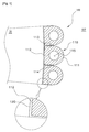
本発明による金属セクターは、誘導加熱式低温溶融炉(以下、“溶融炉”は低温溶融炉をいう)の壁体を構成するもので、壁体100の外側に膨らんで壁体100の外側面をなす外側曲面部111と、壁体100の内側面をなす内側平面部112と、外側曲面部111及び内側平面部112を連結する側平面部113、114とを含む。
Hereinafter, embodiments of the present invention will be described in detail with reference to the accompanying drawings.
The metal sector according to the present invention constitutes a wall body of an induction heating type low temperature melting furnace (hereinafter, “melting furnace” refers to a low temperature melting furnace). An outer
本発明において、金属セクター110は全体としてバー(bar)状を持ち、内部には長手方向に冷却流路が形成されて、冷却水の循環によって溶融炉壁体を冷却させる。 In the present invention, the metal sector 110 has a bar shape as a whole, and a cooling channel is formed in the longitudinal direction in the metal sector 110 to cool the melting furnace wall body by circulating cooling water.
図1は本発明の誘導加熱式低温溶融炉の断面構成を示す図で、溶融炉の一部のみを示しており、同一構造を持つセクターが同一に配置されて全体として溶融炉の形状は円筒状である。 FIG. 1 is a diagram showing a cross-sectional configuration of an induction heating type low temperature melting furnace of the present invention, showing only a part of the melting furnace, sectors having the same structure are arranged in the same manner, and the shape of the melting furnace as a whole is a cylinder. Is.
具体的に、図1を参照すれば、セクター110は、壁体100の外側に膨らんで壁体100の外側面をなす外側曲面部111と、壁体100の内側面をなす内側平面部112と、外側曲面部111及び内側平面部112を連結する側平面部113、114とを含む。
各セクター110は、長手方向に一つまたはそれ以上の冷却流路115が形成されて、冷却水が循環して溶融炉壁体の冷却がなされる。
内側平面部111と側平面部113、114の接する角はラウンド状を持つか面取りされることができる。
Specifically, referring to FIG. 1, the sector 110 includes an outer
In each sector 110, one or
An angle at which the
セクターの材質はステンレススチールを用いることができ、各セクターの間は絶縁物質が設けられて電気的な絶縁がなされる。好ましくは、本発明において、各セクター間の電気的な絶縁は少なくともセクターの内側平面部112及び側平面部113、114にコートされる絶縁層120によって提供できる。
The sector material can be stainless steel, and an insulating material is provided between the sectors to provide electrical insulation. Preferably, in the present invention, electrical insulation between each sector can be provided by an
絶縁層120としては電気絶縁性に優れた多様な材料を用いることができ、好ましくは電気絶縁性のほかに耐磨耗性、耐食性などに優れて効果的な絶縁体物質として利用可能なアルミナ、ジルコニア、ジルコニウムが使用できる。このような絶縁層120は、電気絶縁のほかに熱を緩衝する機能を有することができる。一方、絶縁層120が塗布されるセクターの表面112には凹凸または粗さ(roughness)を持つようにして、コーティング結合力を向上させることができる。
A variety of materials having excellent electrical insulation can be used as the
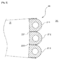
図2を参照すれば、本発明において、各セクターは図1のような形状を持ち、別途の絶縁層をコーティングせずに、各セクター211、212、213の間には電気絶縁のために雲母などの絶縁板221、222が挿入されて、セクター間の電気的な絶縁をなすことができる。
Referring to FIG. 2, in the present invention, each sector has a shape as shown in FIG. 1, and a mica for electrical insulation is provided between the
前述したように、本発明において、セクターは、長手方向に冷却流体が流れる中空部が形成され、特に本発明によるそれぞれの金属セクターは、一つの中空部のみが形成されて、冷却流体の循環がなされることを特徴とする。
二つ以上の中空部が形成されて冷却流体が循環する従来の金属セクターに比べ、本発明の金属セクターは、一つの中空部だけでもセクターの冷却が可能なので、単位金属セクターのサイズを減らすことができる。
As described above, in the present invention, the sector is formed with a hollow portion through which the cooling fluid flows in the longitudinal direction, and in particular, each metal sector according to the present invention is formed with only one hollow portion to circulate the cooling fluid. It is made to be made.
Compared with the conventional metal sector where two or more hollow parts are formed and the cooling fluid circulates, the metal sector of the present invention can cool the sector with only one hollow part, thus reducing the size of the unit metal sector. Can do.
また、冷却流入及び流出のために一つのセクターに二つの中空部を要する従来の金属セクターに比べ、本発明の金属セクターは、一つの中空部のみによって冷却流体の循環が可能なので、セクターの設計時にセクターの全体サイズを大きく変更することなく、必要な冷却流体流量に対する冷却流路のサイズ変更が容易で設計自由度が高く、溶融壁体における誘導電流の吸収を最小化し、溶融炉の運転効率を高めることができる。 Also, compared to the conventional metal sector, which requires two hollow parts in one sector for cooling inflow and outflow, the metal sector of the present invention can circulate the cooling fluid by only one hollow part. Sometimes it is easy to resize the cooling channel for the required cooling fluid flow without greatly changing the overall size of the sector, and the design flexibility is high, the absorption of the induced current in the molten wall is minimized, and the operating efficiency of the melting furnace Can be increased.
具体的に、図3を参照すれば、単位金属セクターは図1または図2の実施例の構成を含むが、隣り合う一対のセクター310、320は冷却流路が互いに連結されて、冷却流体の循環がなされることを特徴とする。
具体的に、隣り合う一対のセクター310、320は、それぞれ一つの第1冷却流路311と第2冷却流路321が形成され、第1及び第2冷却流路311、321は、各セクター310、320の上端または下端で連結配管330を介して連結される。図示は省略するが、第1冷却流路と第2冷却流路には、冷却流体を循環させるために循環ポンプのような冷却流体循環装置が連結される。
Specifically, referring to FIG. 3, the unit metal sector includes the configuration of the embodiment of FIG. 1 or FIG. 2, but the pair of
Specifically, a pair of
例えば、循環ポンプ(図示せず)によって冷却流体が第1冷却流路311を通じて流入し、連結配管330に沿って第2冷却流路321を通じて排出され、循環ポンプに還収されることで、冷却流体の循環がなされるので、互いに隣接して位置する一対のセクター単位で冷却がなされる。
このように一対のセクターを単位として構成された溶融炉は全体的に偶数のセクターで構成されることができる。
For example, the cooling fluid flows in through the first
Thus, the melting furnace configured with a pair of sectors as a unit can be configured with an even number of sectors as a whole.
図4は本発明による誘導加熱式低温溶融炉のさらに他の実施例を示す図であり、同様に単位金属セクターは図1または図2の実施例と同様な構成を含むが、各金属セクターは溶融炉壁体の外側に位置する冷却チューブに連結されて、冷却流体の循環がなされることを特徴とする。 FIG. 4 is a view showing still another embodiment of the induction heating type low temperature melting furnace according to the present invention. Similarly, the unit metal sector includes the same configuration as the embodiment of FIG. 1 or FIG. The cooling fluid is circulated by being connected to a cooling tube located outside the melting furnace wall.
具体的に、図4を参照すれば、各セクター410には、それに対応する冷却チューブ420が設けられ、冷却流路411はセクターの上端または下端で連結配管430を介して冷却チューブ420と連結される。
冷却流路411または冷却チューブ420は図示しない一つまたは複数の共通冷却流体ヘッダーで連結されることができ、冷却流路と冷却チューブは冷却流体循環装置(図示せず)に連結されて、冷却流体の循環がなされることができる。
Specifically, referring to FIG. 4, each
The
図4は一つのセクターに一つの冷却チューブのみが連結されるものを示しているが、二つ以上のセクターが一つの冷却チューブで連結されて、冷却流体の循環がなされることもできる。一方、図4は絶縁層がコートされた各セクターの間に絶縁板が挿入されて壁体をなすものを示す。 Although FIG. 4 shows a case where only one cooling tube is connected to one sector, two or more sectors can be connected by one cooling tube to circulate the cooling fluid. On the other hand, FIG. 4 shows a structure in which an insulating plate is inserted between each sector coated with an insulating layer to form a wall.
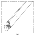
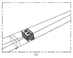
図5は金属セクターの構造的な形状に対する電磁気解釈モデルを示す図であり、(a)は本発明による金属セクター、(b)は従来技術による金属セクターである。
図5の(a)において、本発明による金属セクターの外側にCu誘導コイルが配置され、金属セクターの内側にはガラスと、誘導電流によってガラスに溶融熱を提供するチタンリングがあると仮定して解釈した。図5(b)は従来技術による金属セクターであり、図5(a)と同一条件であるが、一つの金属セクター内に二つの冷却流路が形成された金属セクターの構造に対する解釈結果である。
FIG. 5 is a diagram showing an electromagnetic interpretation model for the structural shape of the metal sector, where (a) is a metal sector according to the present invention and (b) is a metal sector according to the prior art.
In FIG. 5 (a), it is assumed that a Cu induction coil is arranged outside the metal sector according to the present invention, and inside the metal sector is a glass and a titanium ring that provides heat of fusion to the glass by an induced current. Interpreted. FIG. 5B shows a metal sector according to the prior art, which is the interpretation result for the structure of the metal sector in which two cooling channels are formed in one metal sector under the same conditions as FIG. 5A. .
以下の表1は、解釈結果から得たモデル別電流分布の割合(%)を定量的に示すもので、本発明によるセクターの構造は従来技術に比べてガラスに伝達される誘導電流の割合が高いことを確認することができる。 Table 1 below shows quantitatively the ratio (%) of the current distribution by model obtained from the interpretation result. The sector structure according to the present invention has a ratio of induced current transmitted to the glass as compared with the prior art. It can be confirmed that it is expensive.

したがって、本発明による誘導加熱式低温溶融炉は、従来のセクター構造に比べ、運転効率を高めることができる。 Therefore, the induction heating type low temperature melting furnace according to the present invention can increase the operation efficiency as compared with the conventional sector structure.
前記実施例は、本発明の技術的思想を具体的に説明するための一例であり、本発明の範囲は前記の図面や実施例に限定されない。 The embodiments are examples for specifically explaining the technical idea of the present invention, and the scope of the present invention is not limited to the drawings and the embodiments described above.
100 溶融壁体
110 セクター
111 外側曲面部
112 内側平面部
113、114 側平面部
120 絶縁層
DESCRIPTION OF
Claims (8)
前記セクターは、前記壁体の外側に膨らんで前記壁体の外側面をなす外側曲面部と、前記壁体の内側面をなす内側平面部と、前記外側曲面部及び内側平面部を連結する側平面部とを含んでなることを特徴とする、誘導加熱式低温溶融炉。 In an induction heating type low temperature melting furnace including a wall body in which a large number of metal material sectors are insulated by an insulating material,
The sector includes an outer curved surface portion that bulges outside the wall body and forms an outer surface of the wall body, an inner flat surface portion that forms an inner surface of the wall body, and a side that connects the outer curved surface portion and the inner flat surface portion. An induction heating type low temperature melting furnace comprising a flat portion.
前記セクターは、前記壁体の外側に膨らんで前記壁体の外側面をなす外側曲面部と、壁体の内側面をなす内側平面部と、前記外側曲面部及び内側平面部を連結する側平面部とを含んでなることを特徴とする、金属セクター。 In the metal material sector that is electrically insulated from each other and forms the wall of an induction heating type low temperature melting furnace,
The sector includes an outer curved surface portion that swells outside the wall body and forms an outer surface of the wall body, an inner flat surface portion that forms an inner surface of the wall body, and a side plane that connects the outer curved surface portion and the inner flat surface portion. A metal sector, characterized by comprising a part.
The metal sector according to claim 6 or 7, wherein the sector is formed with one hollow portion in a longitudinal direction.
Applications Claiming Priority (1)
| Application Number | Priority Date | Filing Date | Title |
|---|---|---|---|
| PCT/KR2011/007053 WO2013047914A1 (en) | 2011-09-26 | 2011-09-26 | Metal sector having a curved outer surface and cold crucible induction melter comprising same |
Publications (2)
| Publication Number | Publication Date |
|---|---|
| JP2014501901A true JP2014501901A (en) | 2014-01-23 |
| JP2014501901A5 JP2014501901A5 (en) | 2014-11-20 |
Family
ID=47995925
Family Applications (1)
| Application Number | Title | Priority Date | Filing Date |
|---|---|---|---|
| JP2013539738A Pending JP2014501901A (en) | 2011-09-26 | 2011-09-26 | Metal sector with curved outer surface and induction heating type low temperature melting furnace including the same |
Country Status (3)
| Country | Link |
|---|---|
| US (1) | US9265096B2 (en) |
| JP (1) | JP2014501901A (en) |
| WO (1) | WO2013047914A1 (en) |
Cited By (1)
| Publication number | Priority date | Publication date | Assignee | Title |
|---|---|---|---|---|
| US11391516B2 (en) | 2016-11-25 | 2022-07-19 | Korea Hydro & Nuclear Power Co., Ltd | Cold crucible comprising metal oxide barrier and method for manufacturing same |
Citations (4)
| Publication number | Priority date | Publication date | Assignee | Title |
|---|---|---|---|---|
| JPH05264176A (en) * | 1991-10-16 | 1993-10-12 | Shinko Electric Co Ltd | Cold wall induction smelting crusible furnace |
| JPH1174070A (en) * | 1997-08-28 | 1999-03-16 | Fuji Electric Co Ltd | Crucible for floatation dissolution |
| WO2002066915A1 (en) * | 2001-02-20 | 2002-08-29 | Budapesti Muszaki És Gazdaságtudományi Egyetem | Crucible for the induction melting of metals and/or maintaining the temperature of molten metals |
| JP2005517148A (en) * | 2002-02-04 | 2005-06-09 | コミツサリア タ レネルジー アトミーク | Induction furnace |
Family Cites Families (9)
| Publication number | Priority date | Publication date | Assignee | Title |
|---|---|---|---|---|
| US2149008A (en) * | 1937-09-15 | 1939-02-28 | Comb Eng Co Inc | Tube with metallic block and method of attaching latter |
| FR2036418A5 (en) * | 1969-03-13 | 1970-12-24 | Commissariat Energie Atomique | |
| US4058668A (en) | 1976-03-01 | 1977-11-15 | The United States Of America As Represented By The Secretary Of The Interior | Cold crucible |
| JPS5832313B2 (en) * | 1977-12-06 | 1983-07-12 | 山陽特殊製鋼株式会社 | Water cooling panel for electric arc furnace |
| US4738713A (en) | 1986-12-04 | 1988-04-19 | The Duriron Company, Inc. | Method for induction melting reactive metals and alloys |
| US4923508A (en) * | 1989-05-08 | 1990-05-08 | Howmet Corporation | Segmented induction skull melting crucible and method |
| JP5078197B2 (en) * | 2001-04-27 | 2012-11-21 | シンフォニアテクノロジー株式会社 | Induction heating melting furnace |
| JP5000149B2 (en) * | 2006-02-15 | 2012-08-15 | 株式会社神戸製鋼所 | Cold Crucible Induction Dissolver |
| US8080999B2 (en) * | 2008-07-05 | 2011-12-20 | Westerngeco L.L.C. | Sensor cable for electromagnetic surveying |
-
2011
- 2011-09-26 JP JP2013539738A patent/JP2014501901A/en active Pending
- 2011-09-26 US US13/883,801 patent/US9265096B2/en active Active
- 2011-09-26 WO PCT/KR2011/007053 patent/WO2013047914A1/en active Application Filing
Patent Citations (4)
| Publication number | Priority date | Publication date | Assignee | Title |
|---|---|---|---|---|
| JPH05264176A (en) * | 1991-10-16 | 1993-10-12 | Shinko Electric Co Ltd | Cold wall induction smelting crusible furnace |
| JPH1174070A (en) * | 1997-08-28 | 1999-03-16 | Fuji Electric Co Ltd | Crucible for floatation dissolution |
| WO2002066915A1 (en) * | 2001-02-20 | 2002-08-29 | Budapesti Muszaki És Gazdaságtudományi Egyetem | Crucible for the induction melting of metals and/or maintaining the temperature of molten metals |
| JP2005517148A (en) * | 2002-02-04 | 2005-06-09 | コミツサリア タ レネルジー アトミーク | Induction furnace |
Cited By (1)
| Publication number | Priority date | Publication date | Assignee | Title |
|---|---|---|---|---|
| US11391516B2 (en) | 2016-11-25 | 2022-07-19 | Korea Hydro & Nuclear Power Co., Ltd | Cold crucible comprising metal oxide barrier and method for manufacturing same |
Also Published As
| Publication number | Publication date |
|---|---|
| WO2013047914A1 (en) | 2013-04-04 |
| US20130235896A1 (en) | 2013-09-12 |
| US9265096B2 (en) | 2016-02-16 |
Similar Documents
| Publication | Publication Date | Title |
|---|---|---|
| JP5564150B2 (en) | Cold crucible induction melting furnace integrated with induction coil and melting furnace | |
| US8462506B2 (en) | Water-cooled reactor | |
| KR20110097722A (en) | Apparatus for use in direct resistance heating of platinum-containing vessels | |
| JP6383540B2 (en) | Spinning molding equipment | |
| JP2014501901A (en) | Metal sector with curved outer surface and induction heating type low temperature melting furnace including the same | |
| JP5840220B2 (en) | Metal sector with inner curved surface and induction heating type low temperature melting furnace including the same | |
| CN112325641B (en) | Vacuum smelting induction coil device | |
| KR101307741B1 (en) | Cold crucible induction melter including a metal sector having a curved outer surface | |
| US10384253B2 (en) | Spinning forming device | |
| JP5186374B2 (en) | Melting furnace with an inductor device having a single loop of multiple conductors | |
| KR101340876B1 (en) | Metal sector having a curved inner surface and a cold crucible induction melter including the same | |
| US20160262218A1 (en) | High-frequency induction melting furnace | |
| CN209443039U (en) | A kind of bracket bearing longitudinal direction heating quenching inductor | |
| CN105682276A (en) | Novel electromagnetic eddy current heating device | |
| CN102583955A (en) | Direct electric-heating flange used for platinum channel | |
| CN105783246A (en) | Electromagnetic eddy current heating system | |
| CN108050832A (en) | Energy-saving electrical furnace system | |
| JP2022524841A (en) | Electromagnetic devices and systems for pumping, circulating, or transferring non-ferrous molten metals | |
| CN101484594A (en) | Thermal isolation screen for isolating an electromagnetic inductor, and heat treatment installation comprising such a screen | |
| CN110357397A (en) | Electric boosting cooling jacket | |
| CN220755089U (en) | Internal heater of titanium sponge condensation reactor | |
| CN216770166U (en) | Liquid-cooled copper crucible of electromagnetic high-frequency induction furnace | |
| CN217005323U (en) | High temperature induction heating furnace inductor, induction heating furnace | |
| CN201986201U (en) | Circulating water cooling type bottom electrode assembly | |
| CN208688266U (en) | A kind of isolation structure of magnet ring calcining isolation cushion block and application the isolation cushion block |
Legal Events
| Date | Code | Title | Description |
|---|---|---|---|
| A977 | Report on retrieval |
Free format text: JAPANESE INTERMEDIATE CODE: A971007 Effective date: 20140514 |
|
| A131 | Notification of reasons for refusal |
Free format text: JAPANESE INTERMEDIATE CODE: A131 Effective date: 20140701 |
|
| A521 | Written amendment |
Free format text: JAPANESE INTERMEDIATE CODE: A523 Effective date: 20140926 |
|
| A524 | Written submission of copy of amendment under section 19 (pct) |
Free format text: JAPANESE INTERMEDIATE CODE: A524 Effective date: 20140926 |
|
| A521 | Written amendment |
Free format text: JAPANESE INTERMEDIATE CODE: A821 Effective date: 20140926 |
|
| A02 | Decision of refusal |
Free format text: JAPANESE INTERMEDIATE CODE: A02 Effective date: 20150106 |