JP2014233610A - Ultrasonic diagnostic apparatus - Google Patents
Ultrasonic diagnostic apparatus Download PDFInfo
- Publication number
- JP2014233610A JP2014233610A JP2013119300A JP2013119300A JP2014233610A JP 2014233610 A JP2014233610 A JP 2014233610A JP 2013119300 A JP2013119300 A JP 2013119300A JP 2013119300 A JP2013119300 A JP 2013119300A JP 2014233610 A JP2014233610 A JP 2014233610A
- Authority
- JP
- Japan
- Prior art keywords
- difference
- unit
- reference signal
- time
- ultrasonic
- Prior art date
- Legal status (The legal status is an assumption and is not a legal conclusion. Google has not performed a legal analysis and makes no representation as to the accuracy of the status listed.)
- Pending
Links
Images


Landscapes
- Ultra Sonic Daignosis Equipment (AREA)
Abstract
Description
この発明の実施形態は超音波診断装置に関する。 Embodiments described herein relate generally to an ultrasonic diagnostic apparatus.
超音波診断装置は、超音波プローブを用いて被検体内に超音波を送信してその反射波を受信することにより、被検体の生体情報を取得する超音波検査を行うものである。超音波診断装置は、取得した生体情報に基づく超音波画像データを生成し、超音波画像として表示部に表示させる。 The ultrasonic diagnostic apparatus performs an ultrasonic examination to acquire biological information of a subject by transmitting an ultrasonic wave into the subject using an ultrasonic probe and receiving a reflected wave thereof. The ultrasound diagnostic apparatus generates ultrasound image data based on the acquired biological information and displays the ultrasound image data on the display unit as an ultrasound image.
超音波診断装置には、クリップ形状や吸盤形状の心電検知部を介して被検体の心電信号を測定する心電計を有するものがある。超音波診断装置は、測定した心電信号に基づくECG(Electrocardiogram)画像データを生成し、ECG画像を超音波画像とともに表示部に表示させる。ECG画像データ及びECG画像は被検体の心電波形を表す。 Some ultrasonic diagnostic apparatuses include an electrocardiograph that measures an electrocardiogram signal of a subject via a clip-shaped or sucker-shaped electrocardiogram detection unit. The ultrasonic diagnostic apparatus generates ECG (Electrocardiogram) image data based on the measured electrocardiogram signal, and displays the ECG image on the display unit together with the ultrasonic image. The ECG image data and the ECG image represent the electrocardiographic waveform of the subject.
超音波診断装置は、超音波画像データを生成したとき、生成した時間を表す時間情報を当該超音波画像データに付帯する。また、超音波診断装置は、ECG画像を生成したとき、生成した時間を表す時間情報を当該ECG画像データに付帯する。超音波診断装置は、超音波画像データに付帯された時間情報に表された時間と、ECG画像データに付帯された時間情報に表された時間とが最も近い超音波画像データとECG画像データに基づく超音波画像とECG画像とを同じ時相を表す画像としてともに表示部に表示させる。このようにして、超音波診断装置は、生成した画像どうしの時相合わせを行う。なお、超音波診断装置は、超音波画像データに付帯された時間情報に表された時間と、ECG画像データに付帯された時間情報に表された時間とが同一となる超音波画像データとECG画像データとが生成していた場合、該超音波画像データと該ECG画像データとをともに表示部に表示させる。この場合は、前述した、超音波診断装置が、超音波画像データに付帯された時間情報に表された時間と、ECG画像データに付帯された時間情報に表された時間とが最も近い超音波画像データとECG画像データに基づく超音波画像とECG画像とをともに表示部に表示させる概念に包含されるものである。 When the ultrasonic diagnostic apparatus generates ultrasonic image data, time information indicating the generated time is attached to the ultrasonic image data. In addition, when the ECG image is generated, the ultrasonic diagnostic apparatus attaches time information indicating the generated time to the ECG image data. The ultrasonic diagnostic apparatus converts the time indicated in the time information attached to the ultrasonic image data and the time indicated in the time information attached to the ECG image data into the ultrasonic image data and the ECG image data closest to each other. The ultrasonic image based and the ECG image are displayed together on the display unit as images representing the same time phase. In this way, the ultrasonic diagnostic apparatus performs time alignment between the generated images. Note that the ultrasonic diagnostic apparatus uses the ultrasonic image data and the ECG in which the time represented by the time information attached to the ultrasonic image data is the same as the time represented by the time information attached to the ECG image data. When image data has been generated, both the ultrasonic image data and the ECG image data are displayed on the display unit. In this case, the ultrasound diagnosis apparatus described above has the closest time represented by the time information attached to the ultrasound image data and the time represented by the time information attached to the ECG image data. The present invention is included in the concept of displaying both an ultrasonic image and an ECG image based on image data and ECG image data on a display unit.
しかしながら、超音波プローブが被検体からの反射波を受けてから超音波画像データが生成されるまでの時間と、心電検知部が心電信号を受けてからECG画像データが生成されるまでの時間とには差異が生じる。なぜならば、超音波画像データを生成するための信号処理時間と、ECG画像データを生成するための信号処理時間とは異なる時間であるからである。なお、この差異の値は、超音波診断装置の仕様、信号処理条件、若しくは内蔵時計の仕様又はこれらの組み合わせによってことなる値となる場合がある。以下、この差異を時相合わせの誤差と称する。従来の超音波診断装置は、この誤差の時間分時相がずれた超音波画像とECG画像とを同じ時相の画像として表示部に表示させていた。このことは、超音波プローブが被検体からの反射波を受けた時間と心電検知部が心電信号を受けた時間とが異なる超音波画像とECG画像とを同じ時相の画像として表示部に表示することに相当する。それにより、医師等のユーザは、反射波を受けた時間と心電信号を受けた時間とが時相合わせの誤差の時間分異なる超音波画像とECG画像とを同じ時相として表示した表示部の画面を見て診断することとなる。従って、ユーザは、この時相合わせの誤差を考慮しながら診断を行わなければならない場合があった。この診断作業は煩わしく、また、診断の精度が損なわれる場合があった。 However, the time until the ultrasound image data is generated after the ultrasound probe receives the reflected wave from the subject, and the time from when the ECG detection unit receives the ECG signal until the ECG image data is generated. There is a difference in time. This is because the signal processing time for generating ultrasonic image data is different from the signal processing time for generating ECG image data. Note that the difference value may vary depending on the specifications of the ultrasonic diagnostic apparatus, the signal processing conditions, the specifications of the built-in clock, or a combination thereof. Hereinafter, this difference is referred to as a time phase alignment error. In the conventional ultrasonic diagnostic apparatus, an ultrasonic image and an ECG image whose time phases are shifted by the time of the error are displayed on the display unit as images of the same time phase. This is because an ultrasonic image and an ECG image in which the time when the ultrasonic probe receives the reflected wave from the subject and the time when the electrocardiogram detection unit receives the electrocardiogram signal are displayed as the same time phase image. Is equivalent to displaying on the screen. Thereby, a user such as a doctor displays an ultrasonic image and an ECG image in which the time when the reflected wave is received and the time when the electrocardiogram signal is received are different from each other by the time of the phase matching error. Diagnose by looking at the screen. Therefore, the user may have to make a diagnosis in consideration of the error in phase matching. This diagnosis work is cumbersome and the accuracy of diagnosis may be impaired.
本発明が解決しようとする課題は、生成した画像データの時相合わせの誤差を低減することができる超音波診断装置を提供することである。 The problem to be solved by the present invention is to provide an ultrasonic diagnostic apparatus capable of reducing an error in time alignment of generated image data.
実施形態の超音波診断装置は、超音波プローブと、心電計と、超音波画像生成部と、ECG画像生成部と、第1の時間部と、第2の時間部と、基準信号部と、算出部と、記憶部と、表示制御部とを有する。超音波プローブは、被検体に対して超音波を送受信する。心電計は、心電検知部を介して被検体の心電信号を測定する。超音波画像生成部は、超音波プローブで受信した超音波に基づく超音波画像データを生成する。ECG画像生成部は、心電計からの入力に基づくECG画像データを生成する。第1の時間部は、超音波画像データが生成されるごとに、超音波画像データが生成された時間を表す第1の時間情報を超音波画像データに付帯する。第2の時間部は、ECG画像データが生成されるごとに、ECG画像データが生成された時間を表す第2の時間情報をECG画像データに付帯する。基準信号部は、超音波プローブへ第1の基準信号を、心電検知部へ第2の基準信号を、同時に出力する。算出部は、第1の基準信号に基づいて生成された超音波画像データに付帯された第1の時間情報に表される第1の基準時間と第2の基準信号に基づいて生成されたECG画像データに付帯された第2の時間情報に表される第2の基準時間との差分である第1の差分を算出する。記憶部は、第1の差分を記憶する。表示制御部は、第1の時間情報に表される時間と第2の時間情報に表される時間に第1の差分を加えた時間を表す第3の時間情報に表される時間とが最も近い超音波画像データの超音波画像とECG画像データのECG画像とを表示部に表示させる。 The ultrasonic diagnostic apparatus according to the embodiment includes an ultrasonic probe, an electrocardiograph, an ultrasonic image generation unit, an ECG image generation unit, a first time unit, a second time unit, and a reference signal unit. A calculation unit, a storage unit, and a display control unit. The ultrasonic probe transmits and receives ultrasonic waves to and from the subject. The electrocardiograph measures an electrocardiographic signal of a subject via an electrocardiogram detection unit. The ultrasonic image generation unit generates ultrasonic image data based on the ultrasonic waves received by the ultrasonic probe. The ECG image generation unit generates ECG image data based on an input from the electrocardiograph. The first time unit adds first time information indicating the time when the ultrasonic image data is generated to the ultrasonic image data every time the ultrasonic image data is generated. Each time the ECG image data is generated, the second time portion adds second time information indicating the time when the ECG image data is generated to the ECG image data. The reference signal unit simultaneously outputs the first reference signal to the ultrasonic probe and the second reference signal to the electrocardiogram detection unit. The calculation unit generates an ECG generated based on the first reference time and the second reference signal represented by the first time information attached to the ultrasonic image data generated based on the first reference signal. A first difference which is a difference from the second reference time represented by the second time information attached to the image data is calculated. The storage unit stores the first difference. In the display control unit, the time represented by the first time information and the time represented by the third time information representing the time obtained by adding the first difference to the time represented by the second time information are the most. An ultrasonic image of near ultrasonic image data and an ECG image of ECG image data are displayed on the display unit.
〈第1の実施形態〉
[構成]
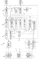
図1は、この実施形態の超音波診断装置1の構成を表すブロック図である。図1において、実線の矢印は、超音波画像又はECG画像に係るデータの流れを表す。破線の矢印は制御信号の流れを表す。二点鎖線の矢印は第1の基準信号又は第2の基準信号の流れを表す。超音波診断装置1は、超音波プローブ2と、心電計3と、基準信号部4と、本体部5と、表示部6と、操作部7とを有する。
<First Embodiment>
[Constitution]
FIG. 1 is a block diagram showing the configuration of the ultrasonic diagnostic apparatus 1 of this embodiment. In FIG. 1, a solid line arrow represents a data flow related to an ultrasonic image or an ECG image. Dashed arrows represent the flow of control signals. A two-dot chain line arrow represents a flow of the first reference signal or the second reference signal. The ultrasonic diagnostic apparatus 1 includes an
(超音波プローブ2)
超音波プローブ2は、被検体に対して超音波を送受信する。超音波プローブ2には、複数の超音波振動子が走査方向に1列に配置された1次元アレイプローブ、または、複数の超音波振動子が2次元的に配置された2次元アレイプローブが用いられる。また、走査方向に1列に配置された複数の超音波振動子を走査方向に直交する揺動方向に揺動させる機械式1次元アレイプローブが用いられてもよい。超音波プローブ2は、送信部13からの電気信号を超音波信号に変換し、被検体へ超音波を送信し、被検体からの反射波を受信する。また、超音波プローブ2は、基準信号部4からの第1の基準信号を受信する。超音波プローブ2は、受信した被検体からの反射波または基準信号部4からの第1の基準信号に基づく信号をエコー信号として超音波受信部14へ出力する。
(Ultrasonic probe 2)
The
(心電計3)
心電計3は、心電検知部8を介して被検体の心電信号を測定する。心電計3は、心電検知部8とECG受信部9とを有する。心電検知部8は、クリップ状の形状や吸盤状の形状に構成され、被検体の腕、脚、胸部等に装着される。心電検知部8は、被検体の心電信号を検知する電極を有し、検知した心電信号をECG受信部9へ出力する。また、心電検知部8は、基準信号部4からの第2の基準信号を受け、ECG受信部9へ出力する。ECG受信部9は、システム制御部21からの制御信号に基づいて、心電検知部8から受けた心電信号または基準信号部4からの第2の基準信号をECG画像処理部17へ出力する。該制御信号は、心電信号の受信条件を表す。例えばECG受信部9は、心電信号のサンプリングレートを表す制御信号をシステム制御部21から受け、該サンプリングレートに基づいて、心電検知部8から受けた心電信号または第2の基準信号をECG画像処理部17へ出力する。
(Electrocardiograph 3)
The electrocardiograph 3 measures an electrocardiographic signal of the subject via the electrocardiogram detection unit 8. The electrocardiograph 3 includes an electrocardiogram detection unit 8 and an ECG reception unit 9. The electrocardiogram detection unit 8 is configured in a clip shape or a sucker shape, and is mounted on the arm, leg, chest, etc. of the subject. The electrocardiogram detection unit 8 includes an electrode that detects an electrocardiogram signal of the subject, and outputs the detected electrocardiogram signal to the ECG reception unit 9. The electrocardiogram detection unit 8 receives the second reference signal from the reference signal unit 4 and outputs the second reference signal to the ECG reception unit 9. Based on the control signal from the
(基準信号部4)
基準信号部4は、超音波プローブ2へ第1の基準信号を、心電検知部8へ第2の基準信号を、同時に出力する。基準信号部4は、第1の基準信号出力部10と、第2の基準信号出力部11と、基準信号制御部12とを有する。
(Reference signal section 4)
The reference signal unit 4 simultaneously outputs the first reference signal to the
(第1の基準信号出力部10)
第1の基準信号出力部10は、超音波プローブ2へ第1の基準信号を出力する。例えば第1の基準信号は、超音波信号である。第1の基準信号としては、ノイズと区別可能な超音波信号が予め設定される。例えば、第1の基準信号は、該第1の基準信号に基づいて生成された超音波画像データにおいて、定められた形状、輝度、若しくは色相またはこれらの組み合わせを表すように予め設定される。この設定の内容を第1の基準信号の設定内容と称す。
(First reference signal output unit 10)
The first reference
(第2の基準信号出力部11)
第2の基準信号出力部11は、心電検知部8へ第2の基準信号を出力する。例えば第2の基準信号は、心電信号を模した電気信号である。第2の基準信号としては、ノイズと区別可能な電気信号が予め設定される。例えば、第2の基準信号は、該第2の基準信号に基づいて生成されたECG画像データにおいて、定められた心電波形を表すように予め設定される。この設定の内容を第2の基準信号の設定内容と称す。
(Second reference signal output unit 11)
The second reference signal output unit 11 outputs the second reference signal to the electrocardiogram detection unit 8. For example, the second reference signal is an electrical signal simulating an electrocardiogram signal. As the second reference signal, an electrical signal that can be distinguished from noise is set in advance. For example, the second reference signal is set in advance so as to represent a predetermined electrocardiographic waveform in the ECG image data generated based on the second reference signal. This setting content is referred to as the setting content of the second reference signal.
(基準信号制御部12)
基準信号制御部12は、第1の基準信号出力部10と第2の基準信号出力部11とが第1の基準信号と第2の基準信号とを同時に出力するための制御信号を、第1の基準信号出力部10と第2の基準信号出力部11とへ出力する。それにより、第1の基準信号と第2の基準信号とが同時に出力される。ここで、同時に出力するとは、後述するカウント部18がカウント信号を出力する時間間隔に対して十分に短い誤差の範囲内のタイミングで、第1の基準信号出力部10と第2の基準信号出力部11とが同時に第1の基準信号と第2の基準信号とを出力することである。また、基準信号制御部12は、第1の基準信号の設定内容を第1の基準信号出力部10へ出力し、第2の基準信号の設定内容を第2の基準信号出力部11へ出力する。基準信号制御部12は、ユーザによる動作開始指示を受け、所定の時間経過した後、前述した制御を行い、第1の基準信号と第2の基準信号とを同時に出力させる。
(Reference signal control unit 12)
The reference
(本体部5)
本体部5は、送信部13と、超音波受信部14と、スキャン制御部15と、超音波画像処理部16と、ECG画像処理部17と、カウント部18と、画像出力制御部19と、記憶部20と、システム制御部21とを有する。
(Main body 5)
The main unit 5 includes a transmission unit 13, an ultrasonic reception unit 14, a scan control unit 15, an ultrasonic
(送信部13)
送信部13は、超音波プローブ2から被検体へ超音波を送信させる。送信部13は、超音波プローブ2へ電気信号を供給して超音波を発生させる。送信部13は、図示しない送信遅延回路及びパルサ回路を有する。送信遅延回路は、送信遅延回路は、超音波の送信時に遅延をかけて送信フォーカスを実施する。パルサ回路は、各超音波振動子に対応した経路(チャンネル)の数に応じたパルサを備え、遅延がかけられた送信タイミングで駆動パルスを発生し、超音波プローブ2の各超音波振動子に供給する。送信部13は、送信フォーカスの位置情報や駆動パルスの繰り返し周波数等の送信条件を表す制御信号をスキャン制御部15から受け、該制御信号に基づいて、超音波プローブ2へ電気信号を供給する。
(Transmitter 13)
The transmission unit 13 transmits ultrasonic waves from the
(超音波受信部14)
超音波受信部14は、超音波プローブ2からのエコー信号を受ける。超音波受信部14は、受けたエコー信号に対して遅延処理を行うことにより、アナログのエコー信号を整相された(受信ビームフォームされた)デジタルの信号に変換する。
(Ultrasonic receiver 14)
The ultrasonic receiver 14 receives an echo signal from the
超音波受信部14は、例えば図示しないプリアンプ回路と、A/D変換器と、受信遅延回路と、加算器とを有する。プリアンプ回路は、超音波プローブ2の各超音波振動子からのエコー信号を受信チャンネルごとに増幅する。A/D変換器は、増幅されたアナログのエコー信号をデジタル信号に変換する。受信遅延回路は、デジタル信号に変換されたエコー信号に、受信指向性を決定するための遅延時間を与える。加算器は、遅延時間が与えられたエコー信号を整相加算する。その整相加算によって、受信指向性に応じた方向からの反射成分が強調される。超音波受信部14は、整相加算した信号を受信信号として超音波画像生成部22へ出力する。超音波受信部14は、受信指向性等の受信条件を表す制御信号をスキャン制御部15から受け、該制御信号に基づいて、受信信号を求め、超音波画像生成部22へ出力する。
The ultrasonic receiver 14 includes, for example, a preamplifier circuit (not shown), an A / D converter, a reception delay circuit, and an adder. The preamplifier circuit amplifies the echo signal from each ultrasonic transducer of the
(スキャン制御部15)
スキャン制御部15は、走査線の数、超音波画像のフレーム数、超音波画像のフレームレート等を表す制御信号をシステム制御部21から受け、該制御信号に基づいて、送信フォーカスの位置情報や駆動パルスの繰り返し周波数等の送信条件を表す制御信号を送信部13へ出力し、また、受信指向性等の受信条件を表す制御信号を超音波受信部14へ出力する。
(Scan control unit 15)
The scan control unit 15 receives a control signal indicating the number of scanning lines, the number of frames of the ultrasonic image, the frame rate of the ultrasonic image, and the like from the
(超音波画像処理部16)
超音波画像処理部16は、超音波受信部14からの受信信号に信号処理を施して超音波画像データを生成する。このとき、超音波画像処理部16は、フィルタ処理等の条件である信号処理条件を表す制御信号をシステム制御部21から受け、該制御信号に基づいて超音波画像データを生成する。超音波画像処理部16は、超音波画像生成部22と、第1の時間部26とを有する。
(Ultrasonic image processing unit 16)
The ultrasonic
(超音波画像生成部22)
超音波画像生成部22は、超音波プローブ2で受信した超音波に基づく超音波画像データを生成する。また、超音波画像生成部22は、超音波画像データを生成するごとに、生成した超音波画像データを第1の時間部26へ出力する。超音波画像生成部22は、Bモード画像生成部23を有する。Bモード画像生成部23は、受信信号を超音波受信部14から受け、受信信号の振幅情報の映像化を行う。このとき、Bモード画像生成部23は、受信信号に対してバンドパスフィルタ処理を行い、バンドパスフィルタ処理が施された受信信号の包絡線を検波し、検波された包絡線のデータに対して対数変換による圧縮処理を施すことによってBモード画像データを生成する。このBモード画像データは、走査線の信号列で表されたデータでもよく、該信号列が直交座標系に変換(スキャンコンバージョン処理)されて表されたデータでもよい。Bモード画像データは、超音波画像データの1例に相当する。
(Ultrasonic image generation unit 22)
The ultrasonic
また、Bモード画像生成部23は、1本の走査線における1次元の画像を時間軸に沿って並べることによりMモード画像データを生成してもよい。例えば表示部6にBモード画像が表示されている場合、システム制御部21は、操作部7から走査線の指定を受け、指定された走査線の位置情報をBモード画像生成部23に出力する。Bモード画像生成部23は、走査線の位置情報に基づいて、指定された走査線における受信信号を用いてMモード画像データを生成する。Mモード画像データは、超音波画像データの1例に相当する。
The B-mode image generation unit 23 may generate M-mode image data by arranging one-dimensional images on one scanning line along the time axis. For example, when a B-mode image is displayed on the display unit 6, the
また、超音波画像生成部22は、ドプラ画像生成部24を有してもよい。ドプラ画像生成部24は、受信信号を位相検波することによりドプラ偏移周波数成分を取り出し、FFT(Fast Fourier Transform)処理を施すことにより血流速度の時間変化を表すドプラ画像データを生成する。例えばドプラ画像生成部24は、ドプラ偏移周波数分布を、縦軸に周波数、横軸に時間、周波数成分ごとの強さを輝度(諧調)としてスペクトラム表示したドプラ画像データを生成する。ドプラ画像データは、超音波画像データの1例に相当する。
Further, the ultrasonic
また、超音波画像生成部22は、CFM(Color Flow Mapping)画像生成部25を有してもよい。CFM画像生成部25は、定められた走査領域における血流情報の分布を表すCFM画像データを生成する。血流情報には、速度、分散、又はパワーなどの情報が含まれる。血流情報は、例えば色相情報として生成される。このCFM画像データは、走査線の信号列で表されたデータでもよく、該信号列が直交座標系に変換(スキャンコンバージョン処理)されて表されたデータでもよい。CFM画像データは、超音波画像データの1例に相当する。
Further, the ultrasonic
(第1の時間部26)
第1の時間部26は、超音波画像データが生成されるごとに、超音波画像データが生成された時間を表す第1の時間情報を超音波画像データに付帯する。第1の時間部26は、カウント部18からカウント信号を逐次受けている(カウント部18については後述する)。第1の時間部26は、超音波画像生成部22から超音波画像データを受け、超音波画像データを受けたときのカウント信号に表される時間を第1の時間情報として該超音波画像データに付帯する。第1の時間部26は、第1の時間情報を付帯した超音波画像データを画像出力制御部19へ出力する。
(First time part 26)
Each time the ultrasonic image data is generated, the
(ECG画像処理部17)
ECG画像処理部17は、ECG受信部9からの心電信号に信号処理を施してECG画像データを生成する。このとき、ECG画像処理部17は、フィルタ処理等の条件である信号処理条件を表す制御信号をシステム制御部21から受け、該制御信号に基づいてECG画像データを生成する。ECG画像処理部17は、ECG画像生成部27と、第2の時間部28とを有する。
(ECG image processing unit 17)
The ECG
(ECG画像生成部27)
ECG画像生成部27は、心電計3からの入力に基づくECG画像データを生成する。例えばECG画像生成部27は、ECG受信部9から心電信号を受け、被検体の心電波形を表すECG画像データを生成する。また、ECG画像生成部27は、ECG画像データを生成するごとに、生成したECG画像データを第2の時間部28へ出力する。
(ECG image generation unit 27)
The ECG
(第2の時間部28)
第2の時間部28は、ECG画像データが生成されるごとに、ECG画像データが生成された時間を表す第2の時間情報をECG画像データに付帯する。第2の時間部28は、カウント部18からカウント信号を逐次受けている(カウント部18については後述する)。第2の時間部28は、ECG画像生成部27からECG画像データを受け、ECG画像データを受けたときのカウント信号に表される時間を第2の時間情報として該ECG画像データに付帯する。第2の時間部28は、第2の時間情報を付帯したECG画像データを画像出力制御部19へ出力する。
(Second time part 28)
Each time ECG image data is generated, the
(カウント部18)
カウント部18は、一定の時間間隔ごとにカウント信号を第1の時間部26及び第2の時間部28へ出力する。カウント信号は、所定の時刻からの経過時間を表す信号である。例えば所定の時刻には、超音波診断における超音波の送受信開始時刻若しくは基準信号部4の起動時刻またはこれらの双方が含まれる。カウント部18はクロックを有し、該クロックのクロック周波数に基づいて、カウント信号を生成し、一定の時間間隔ごとにカウント信号を出力する。該時間間隔は、超音波画像生成部22が超音波画像データを生成する時間間隔(超音波画像データのフレームレート)と、ECG画像生成部27がECG画像データを生成する時間間隔(ECG画像データのフレームレート)とに基づいて予め設計される。
(Counter 18)
The count unit 18 outputs a count signal to the
(画像出力制御部19)
画像出力制御部19は、超音波画像処理部16から受けた超音波画像データと、ECG画像処理部17から受けたECG画像データとを記憶部20に記憶させる。また、画像出力制御部19は、算出部29と表示制御部30とを有する。
(Image output control unit 19)
The image output control unit 19 causes the
(算出部29)
算出部29は、第1の基準信号に基づいて生成された超音波画像データに付帯された第1の時間情報に表される第1の基準時間と第2の基準信号に基づいて生成されたECG画像データに付帯された第2の基準時間との差分である第1の差分を算出する。
(Calculation unit 29)
The calculation unit 29 is generated based on the first reference time and the second reference signal represented by the first time information attached to the ultrasonic image data generated based on the first reference signal. A first difference that is a difference from the second reference time attached to the ECG image data is calculated.
算出部29は、記憶部20に記憶された超音波画像データから、第1の基準信号に基づいて生成された超音波画像データを選択する。該超音波画像データは、第1の基準信号の設定内容に基づく形状、輝度、若しくは色相またはこれらの組み合わせを表す。算出部29は、基準信号制御部12からの入力またはユーザによる入力によって第1の基準信号の設定内容を受け、受けた設定内容に相当する超音波画像データを記憶部20に記憶された超音波画像データから検索し、該当した超音波画像データを第1の基準信号に基づいて生成された超音波画像データとして選択する。
The calculation unit 29 selects ultrasonic image data generated based on the first reference signal from the ultrasonic image data stored in the
また、算出部29は、記憶部20に記憶されたECG画像データから、第2の基準信号に基づいて生成されたECG画像データを選択する。該ECG画像データは、第2の基準信号の設定内容に基づく心電波形を表す。算出部29は、基準信号制御部12からの入力またはユーザによる入力によって第2の基準信号の設定内容を受け、受けた設定内容に相当するECG画像データを記憶部20に記憶されたECG画像データから検索し、該当したECG画像データを第2の基準信号に基づいて生成されたECG画像データとして選択する。
Further, the calculation unit 29 selects ECG image data generated based on the second reference signal from the ECG image data stored in the
算出部29は、選択した超音波画像データに付帯された第1の時間情報と選択したECG画像データに付帯された第2の時間情報とを参照し、該第1の時間情報に表される時間と該第2の時間情報に表される時間との差分を第1の差分として算出する。算出部29は、算出した第1の差分を記憶部20へ出力し、記憶させる。
The calculation unit 29 refers to the first time information attached to the selected ultrasound image data and the second time information attached to the selected ECG image data, and is represented in the first time information. A difference between the time and the time represented by the second time information is calculated as the first difference. The calculation unit 29 outputs the calculated first difference to the
図2は第1の差分についての概略を表す模式図である。時刻txは、基準信号部4の動作開始時刻を表す。時刻t0は、超音波プローブ2が第1の基準信号を受けた時刻及び心電検知部8が第2の基準信号を受けた時刻である。時刻t1は、第1の基準信号に基づいて生成された超音波画像データに第1の時間情報が付帯された時刻である。時刻t2は、第2の基準信号に基づいて生成されたECG画像データに第2の時間情報が付帯された時刻である。超音波プローブ2が第1の基準信号を受けてから該第1の基準信号に基づいて生成された超音波画像データに第1の時間情報が付帯されるまでの時間s1と、心電検知部8が第2の基準信号を受けてから該第2の基準信号に基づいて生成されたECG画像データに第2の時間情報が付帯されるまでの時間s2とには差分d1が生じる。算出部29はこの差分d1を第1の差分として算出する。
FIG. 2 is a schematic diagram showing an outline of the first difference. Time tx represents the operation start time of the reference signal unit 4. Time t0 is the time when the
(表示制御部30)
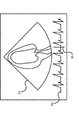
表示制御部30は、第1の時間情報に表される時間と第2の時間情報に表される時間に第1の差分を加えた時間を表す第3の時間情報に表される時間とが最も近い超音波画像データの超音波画像とECG画像データのECG画像とを表示部6に表示させる。図3は、表示部6に表示された超音波画像P1及びECG画像P2の概略を表す模式図である。表示制御部30は、記憶部20から第1の差分を読み出す。また、表示制御部30は、記憶部20に記憶された超音波画像データのそれぞれについて付帯された第1の時間情報を読み、また、記憶部20に記憶されたECG画像データのそれぞれにについて付帯された第2の時間情報を読むとともに第2の時間情報が表す時間に第1の差分を加えた時間を表す第3の時間情報を求める。表示制御部30は、第1の時間情報に表される時間と第3の時間情報に表される時間とが最も近い超音波画像データとECG画像データとを記憶部20から読み出し、該超音波画像データの超音波画像と該ECG画像データのECG画像とを表示部6に表示させる。例えば、表示制御部30は、ユーザによる超音波画像データの指定を受け、指定された超音波画像データに付帯された第1の時間情報が表す時間に最も近い時間を表す第3の時間情報のECG画像データを記憶部20に記憶されたECG画像データから選択し、該超音波画像データの超音波画像と該ECG画像データのECG画像とを表示部6に表示させる。また、表示制御部30は、ユーザによるECG画像データの指定を受け、指定されたECG画像データの第3の時間情報が表す時間に最も近い時間を表す第1の時間情報が付帯された超音波画像データを記憶部20に記憶された超音波画像データから選択し、該ECG画像データのECG画像と該超音波画像データの超音波画像とを表示部6に表示させてもよい。なお、マーカMは、表示されている超音波画像P1の時相をECG画像の時間軸において示すものである。
(Display control unit 30)
The display control unit 30 includes a time represented by the first time information and a time represented by the third time information representing a time obtained by adding the first difference to the time represented by the second time information. The ultrasonic image of the closest ultrasonic image data and the ECG image of the ECG image data are displayed on the display unit 6. FIG. 3 is a schematic diagram showing an outline of the ultrasonic image P1 and the ECG image P2 displayed on the display unit 6. The display control unit 30 reads the first difference from the
なお、表示制御部30は、第1の時間情報に表された時間と、第3の時間情報に表された時間とが同一となる超音波画像データとECG画像データとが記憶部20に記憶されていた場合、該超音波画像データと該ECG画像データとをともに表示部6に表示させる。この場合は、前述した、表示制御部30が、第1の時間情報に表された時間と、第3の時間情報に表された時間とが最も近い超音波画像データとECG画像データに基づく超音波画像とECG画像とをともに表示部6に表示させる概念に包含されるものである。
The display control unit 30 stores in the
(記憶部20)
記憶部20は、画像出力制御部19からの入力を受け、超音波画像データ、ECG画像データ、及び第1の差分を記憶する。前述したように、記憶部20が記憶する超音波画像データには第1の時間情報が付帯され、また、記憶部20が記憶するECG画像データには第2の時間情報が付帯されている。
(Storage unit 20)
The
(システム制御部21)
システム制御部21は、超音波診断装置1の各部を制御する。システム制御部21は、超音波診断装置1の各部の機能を実行するためのコンピュータプログラムを予め記憶する。システム制御部21は、該コンピュータプログラムを実行することで、各部の機能を実現する。
(System control unit 21)
The
(表示部6)
表示部6は、超音波画像及びECG画像を表示する。表示部6は、例えば、CRT(Cathode Ray Tube)やLCD(Liquid Crystal Display)などの表示デバイスで構成される。
(Display unit 6)
The display unit 6 displays an ultrasonic image and an ECG image. The display unit 6 includes a display device such as a CRT (Cathode Ray Tube) or an LCD (Liquid Crystal Display).
(操作部7)
操作部7は、ユーザによる操作を受けて、この操作の内容に応じた信号や情報を装置各部へシステム制御部21を介して入力する。操作部7は、例えば、キーボード、マウス、タッチパネルなどによって構成される。
(Operation unit 7)
In response to an operation by the user, the operation unit 7 inputs signals and information corresponding to the contents of the operation to each unit via the
[動作]
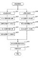
図4は、この実施形態の超音波診断装置1の動作を表すフローチャートである。
[Operation]
FIG. 4 is a flowchart showing the operation of the ultrasonic diagnostic apparatus 1 of this embodiment.
(S001)
超音波診断装置1は、第1の差分を算出する。このステップの詳細については後述する。
(S001)
The ultrasonic diagnostic apparatus 1 calculates the first difference. Details of this step will be described later.
(S002)
超音波診断装置1は、超音波検査を行い、第1の時間情報に表される時間と第2の時間情報に表される時間に第1の差分を加えた時間を表す第3の時間情報に表される時間とが最も近い超音波画像データの超音波画像とECG画像データのECG画像とを表示部6に表示させる。このステップの詳細については後述する。
(S002)
The ultrasonic diagnostic apparatus 1 performs ultrasonic examination, and third time information representing a time obtained by adding a first difference to the time represented by the first time information and the time represented by the second time information. The display unit 6 displays the ultrasonic image of the ultrasonic image data and the ECG image of the ECG image data that are closest in time. Details of this step will be described later.
図5は、超音波診断装置1が第1の差分を算出する動作を表すフローチャートである。 FIG. 5 is a flowchart showing an operation in which the ultrasonic diagnostic apparatus 1 calculates the first difference.
(S101)
基準信号部4は、超音波プローブ2へ第1の基準信号を、心電検知部8へ第2の基準信号を、同時に出力する。
(S101)
The reference signal unit 4 simultaneously outputs the first reference signal to the
(S102)
超音波プローブ2は、基準信号部4からの第1の基準信号を受信する。超音波プローブ2は、基準信号部4からの第1の基準信号に基づく信号をエコー信号として超音波受信部14へ出力する。
(S102)
The
(S103)
超音波受信部14は、超音波プローブ2からのエコー信号を受ける。超音波受信部14は、受けたエコー信号に対して遅延処理を行うことにより、アナログのエコー信号を整相されたデジタルの信号に変換し、受信信号として超音波画像生成部22へ出力する。
(S103)
The ultrasonic receiver 14 receives an echo signal from the
(S104)
超音波画像生成部22は、超音波受信部14からの受信信号を受け、超音波プローブ2で受信した超音波に基づく超音波画像データを生成する。超音波画像生成部22は、生成した超音波画像データを第1の時間部26へ出力する。
(S104)
The ultrasonic
(S105)
第1の時間部26は、超音波画像生成部22から超音波画像データを受け、超音波画像データを受けたときのカウント信号に表される時間を第1の時間情報として該超音波画像データに付帯する。第1の時間部26は、第1の時間情報を付帯した超音波画像データを画像出力制御部19へ出力する。
(S105)
The
(S106)
画像出力制御部19は、第1の時間情報が付帯された超音波画像データを受け、記憶部20に記憶させる。
(S106)
The image output control unit 19 receives the ultrasonic image data attached with the first time information, and stores it in the
(S107)
心電検知部8は、基準信号部4からの第2の基準信号を検知し、ECG受信部9へ出力する。ECG受信部9は、心電検知部8から受けた第2の基準信号をECG画像生成部27へ出力する。
(S107)
The electrocardiogram detection unit 8 detects the second reference signal from the reference signal unit 4 and outputs it to the ECG reception unit 9. The ECG reception unit 9 outputs the second reference signal received from the electrocardiogram detection unit 8 to the ECG
(S108)
ECG画像生成部27は、心電計3からの入力に基づくECG画像データを生成する。ECG画像生成部27は、生成したECG画像データを第2の時間部28へ出力する。
(S108)
The ECG
(S109)
第2の時間部28は、ECG画像生成部27からECG画像データを受け、ECG画像データを受けたときのカウント信号に表される時間を第2の時間情報として該ECG画像データに付帯する。第2の時間部28は、第2の時間情報を付帯したECG画像データを画像出力制御部19へ出力する。
(S109)
The
(S110)
画像出力制御部19は、ECG画像データを受け、記憶部20に記憶させる。
(S110)
The image output control unit 19 receives the ECG image data and stores it in the
なお、ステップS101からステップS106までの処理群と、ステップS107からステップS110までの処理群とは並列処理の関係である。 The processing group from step S101 to step S106 and the processing group from step S107 to step S110 have a parallel processing relationship.
(S111)
算出部29は、記憶部20に記憶された超音波画像データから、第1の基準信号に基づいて生成された超音波画像データを選択する。また、算出部29は、記憶部20に記憶されたECG画像データから、第2の基準信号に基づいて生成されたECG画像データを選択する。
(S111)
The calculation unit 29 selects ultrasonic image data generated based on the first reference signal from the ultrasonic image data stored in the
(S112)
算出部29は、選択した超音波画像データに付帯された第1の時間情報と選択したECG画像データに付帯された第2の時間情報とを参照し、該第1の時間情報に表される時間と該第2の時間情報に表される時間との差分を第1の差分として算出する。算出部29は、算出した第1の差分を記憶部20へ出力し、記憶させる。
(S112)
The calculation unit 29 refers to the first time information attached to the selected ultrasound image data and the second time information attached to the selected ECG image data, and is represented in the first time information. A difference between the time and the time represented by the second time information is calculated as the first difference. The calculation unit 29 outputs the calculated first difference to the
図6は、超音波診断装置1が超音波検査を行う動作を表すフローチャートである。 FIG. 6 is a flowchart showing an operation in which the ultrasonic diagnostic apparatus 1 performs an ultrasonic examination.
(S201)
送信部13は、超音波プローブ2へ電気信号を供給して超音波を発生させる。超音波プローブ2は、送信部13からの電気信号を超音波信号に変換し、被検体へ超音波を送信し、被検体からの反射波を受信する。超音波プローブ2は、受信した被検体からの反射波に基づく信号をエコー信号として超音波受信部14へ出力する。
(S201)
The transmission unit 13 supplies an electric signal to the
(S202)
超音波受信部14は、超音波プローブ2からのエコー信号を受ける。超音波受信部14は、受けたエコー信号に対して遅延処理を行うことにより、アナログのエコー信号を整相されたデジタルの信号に変換し、受信信号として超音波画像生成部22へ出力する。
(S202)
The ultrasonic receiver 14 receives an echo signal from the
(S203)
超音波画像生成部22は、超音波受信部14からの受信信号を受け、超音波プローブ2で受信した超音波に基づく超音波画像データを生成する。超音波画像生成部22は、超音波画像データを生成するごとに、生成した超音波画像データを第1の時間部26へ出力する。
(S203)
The ultrasonic
(S204)
第1の時間部26は、超音波画像生成部22から超音波画像データを受け、超音波画像データを受けたときのカウント信号に表される時間を第1の時間情報として該超音波画像データに付帯する。第1の時間部26は、第1の時間情報を付帯した超音波画像データを画像出力制御部19へ出力する。
(S204)
The
(S205)
画像出力制御部19は、第1の時間情報が付帯された超音波画像データを受け、記憶部20に記憶させる。
(S205)
The image output control unit 19 receives the ultrasonic image data attached with the first time information, and stores it in the
(S206)
心電検知部8は、被検体の心電信号を検知し、検知した心電信号をECG受信部9へ出力する。ECG受信部9は、心電検知部8から受けた心電信号をECG画像生成部27へ出力する。
(S206)
The electrocardiogram detection unit 8 detects an electrocardiogram signal of the subject and outputs the detected electrocardiogram signal to the ECG reception unit 9. The ECG reception unit 9 outputs the electrocardiogram signal received from the electrocardiogram detection unit 8 to the ECG
(S207)
ECG画像生成部27は、ECG受信部9から心電信号を受け、被検体の心電波形を表すECG画像データを生成する。ECG画像生成部27は、ECG画像データを生成するごとに、生成したECG画像データを第2の時間部28へ出力する。
(S207)
The
(S208)
第2の時間部28は、ECG画像生成部27からECG画像データを受け、ECG画像データを受けたときのカウント信号に表される時間を第2の時間情報として該ECG画像データに付帯する。第2の時間部28は、第2の時間情報を付帯したECG画像データを画像出力制御部19へ出力する。
(S208)
The
(S209)
画像出力制御部19は、第2の時間情報が付帯されたECG画像データを受け、記憶部20に記憶させる。
(S209)
The image output control unit 19 receives the ECG image data attached with the second time information and stores it in the
なお、ステップS201からステップS205までの処理群と、ステップS206からステップS209までの処理群とは並列処理の関係である。 Note that the processing group from step S201 to step S205 and the processing group from step S206 to step S209 have a parallel processing relationship.
(S210)
表示制御部30は、記憶部20から第1の差分を読み出す。また、表示制御部30は、記憶部20に記憶された超音波画像データのそれぞれについて付帯された第1の時間情報を読み、また、記憶部20に記憶されたECG画像データのそれぞれについて付帯された第2の時間情報を読むとともに第2の時間情報が表す時間に第1の差分を加えた時間を表す第3の時間情報を求める。
(S210)
The display control unit 30 reads the first difference from the
(S211)
表示制御部30は、第1の時間情報に表される時間と第3の時間情報に表される時間とが最も近い超音波画像データとECG画像データとを記憶部20から読み出し、該超音波画像データの超音波画像と該ECG画像データのECG画像とを表示部6に表示させる。
(S211)
The display control unit 30 reads the ultrasound image data and the ECG image data having the closest time represented by the first time information and the time represented by the third time information from the
[効果]
この実施形態の超音波診断装置1の効果について説明する。超音波診断装置1は、超音波プローブ2と、心電計3と、超音波画像生成部22と、ECG画像生成部27と、第1の時間部26と、第2の時間部28と、基準信号部4と、算出部29と、記憶部20と、表示制御部30とを有する。超音波プローブ2は、被検体に対して超音波を送受信する。心電計3は、心電検知部8を介して被検体の心電信号を測定する。超音波画像生成部22は、超音波プローブ2で受信した超音波に基づく超音波画像データを生成する。ECG画像生成部27は、心電計3からの入力に基づくECG画像データを生成する。第1の時間部26は、超音波画像データが生成されるごとに、超音波画像データが生成された時間を表す第1の時間情報を超音波画像データに付帯する。第2の時間部28は、ECG画像データが生成されるごとに、ECG画像データが生成された時間を表す第2の時間情報をECG画像データに付帯する。基準信号部4は、超音波プローブ2へ第1の基準信号を、心電検知部8へ第2の基準信号を、同時に出力する。算出部29は、第1の基準信号に基づいて生成された超音波画像データに付帯された第1の時間情報に表される第1の基準時間と第2の基準信号に基づいて生成されたECG画像データに付帯された第2の時間情報に表される第2の基準時間との差分である第1の差分を算出する。記憶部20は、第1の差分を記憶する。表示制御部30は、第1の時間情報に表される時間と第2の時間情報に表される時間に第1の差分を加えた時間を表す第3の時間情報に表される時間とが最も近い超音波画像データの超音波画像とECG画像データのECG画像とを表示部6に表示させる。このように、超音波診断装置1は、超音波プローブ2が第1の基準信号を受けてから該第1の基準信号に基づいて生成された超音波画像データに第1の時間情報が付帯されるまでの時間と、心電検知部8が第2の基準信号を受けてから該第2の基準信号に基づいて生成されたECG画像データに第2の時間情報が付帯されるまでの時間との差分を予め算出し、この差分の時間だけずらした時間情報に基づいて、超音波画像データとECG画像データとの時相合わせを行う。それにより、超音波診断装置1は、生成した画像データの時相合わせの誤差を低減することができる。
[effect]
The effect of the ultrasonic diagnostic apparatus 1 of this embodiment will be described. The ultrasound diagnostic apparatus 1 includes an
〈第1の実施形態の変形例〉
[構成]
記憶部20が第1の差分を記憶した後にある程度の期間が経過すると、クロックの累積誤差、若しくは超音波診断装置1の部品交換による信号処理時間の変化、またはこれらの双方が生じる場合がある。この場合、超音波プローブ2が第1の基準信号を受けてから該第1の基準信号に基づいて生成された超音波画像データに第1の時間情報が付帯されるまでの時間と、心電検知部8が第2の基準信号を受けてから該第2の基準信号に基づいて生成されたECG画像データに第2の時間情報が付帯されるまでの時間との差分が記憶した第1の差分と異なることがある。この変形例の超音波診断装置1は、第1の差分を新たに算出し、記憶する。以下、第1の実施形態の超音波診断装置1と異なる事項について特に説明する。
<Modification of First Embodiment>
[Constitution]
When a certain period of time elapses after the
基準信号部4は、記憶部20が第1の差分を記憶した後、新たに第1の基準信号と第2の基準信号とを同時に出力する。基準信号部4により出力された新たな第1の基準信号は、第1の実施形態の超音波診断装置1と同様に、超音波プローブ2において受信され、超音波受信部14においてデジタルの受信信号に変換され、超音波画像生成部22において超音波画像データとして生成され、第1の時間部26において第1の時間情報を付帯される。記憶部20は、新たな第1の基準信号に基づいて生成され、第1の時間情報を付帯された超音波画像データを記憶する。
After the
また、基準信号部4により出力された新たな第2の基準信号は、第1の実施形態の超音波診断装置1と同様に、心電検知部8において検知され、ECG受信部9からECG画像生成部27へ出力され、ECG画像生成部27においてECG画像データとして生成され、第2の時間部28において第2の時間情報を付帯される。記憶部20は、新たな第2の基準信号に基づいて生成され、第2の時間情報を付帯されたECG画像データを記憶する。
Also, the new second reference signal output by the reference signal unit 4 is detected by the electrocardiogram detection unit 8 as in the ultrasound diagnostic apparatus 1 of the first embodiment, and the ECG image is received from the ECG reception unit 9. The data is output to the
算出部29は、新たな第1の基準時間と新たな第2の基準時間との差分を新たな第1の差分として算出する。このとき算出部29は、記憶部20に記憶された超音波画像データから、新たな第1の基準信号に基づいて生成された超音波画像データを選択する。また、算出部29は、記憶部20に記憶されたECG画像データから、新たな第2の基準信号に基づいて生成されたECG画像データを選択する。算出部29は、該超音波画像データに付帯された第1の時間情報と該ECG画像データに付帯された第2の時間情報とを参照し、該第1の時間情報に表される新たな第1の基準時間と該第2の時間情報に表される新たな第2の基準時間との差分を新たな第1の差分として算出する。算出部29は、算出した新たな第1の差分を記憶部20へ出力する。記憶部20は、記憶していた第1の差分に替えて、算出部29からの新たな第1の差分を記憶する。
The calculation unit 29 calculates a difference between the new first reference time and the new second reference time as a new first difference. At this time, the calculation unit 29 selects ultrasonic image data generated based on the new first reference signal from the ultrasonic image data stored in the
なお、記憶部20が第1の差分を記憶してから新たな第1の差分を記憶するまでの期間は、装置により適宜設定されてよいものである。また、基準信号部4は、記憶部20が第1の差分を記憶し、そして定められた期間が経過するごとに、新たに第1の基準信号と第2の基準信号とを同時に出力してもよい。この場合、算出部29は、定められた期間が経過するごとに、新たな第1の差分を算出する。また、記憶部20は、定められた期間が経過するごとに、記憶していた第1の差分に替えて、算出部29からの新たな第1の差分を記憶する。このように、超音波診断装置1は、定められた期間ごとに自動的に新たな第1の差分を算出し、記憶してもよい。
Note that the period from when the
[動作]
図7は、変形例の超音波診断装置1の動作を表すフローチャートである。
[Operation]
FIG. 7 is a flowchart showing the operation of the ultrasonic diagnostic apparatus 1 according to the modification.
(S301)
基準信号部4は、新たに第1の基準信号と第2の基準信号とを同時に出力する。
(S301)
The reference signal unit 4 newly outputs a first reference signal and a second reference signal simultaneously.
(S302)
超音波診断装置1は、基準信号部4により出力された新たな第1の基準信号について、図5のステップS102からステップS106までと同様の処理を施す。それにより、記憶部20は新たな第1の基準信号に基づいて生成され、第1の時間情報を付帯された超音波画像データを記憶する。
(S302)
The ultrasonic diagnostic apparatus 1 performs the same processing as in steps S102 to S106 in FIG. 5 on the new first reference signal output by the reference signal unit 4. Thereby, the memory |
(S303)
超音波診断装置1は、基準信号部4により出力された新たな第2の基準信号について、図5のステップS107からステップS110までと同様の処理を施す。それにより、記憶部20は、新たな第2の基準信号に基づいて生成され、第2の時間情報を付帯されたECG画像データを記憶する。
(S303)
The ultrasonic diagnostic apparatus 1 performs the same processing as in steps S107 to S110 in FIG. 5 on the new second reference signal output by the reference signal unit 4. Thereby, the
なお、ステップS302とステップS303とは並列処理の関係である。 Step S302 and step S303 have a parallel processing relationship.
(S304)
算出部29は、記憶部20に記憶された超音波画像データから、新たな第1の基準信号に基づいて生成された超音波画像データを選択する。また、算出部29は、記憶部20に記憶されたECG画像データから、新たな第2の基準信号に基づいて生成されたECG画像データを選択する。
(S304)
The calculation unit 29 selects ultrasonic image data generated based on the new first reference signal from the ultrasonic image data stored in the
(S305)
算出部29は、選択した超音波画像データに付帯された第1の時間情報と選択したECG画像データに付帯された第2の時間情報とを参照し、該第1の時間情報に表される新たな第1の基準時間と該第2の時間情報に表される新たな第2の基準時間との差分を新たな第1の差分として算出する。算出部29は、算出した新たな第1の差分を記憶部20へ出力する。
(S305)
The calculation unit 29 refers to the first time information attached to the selected ultrasound image data and the second time information attached to the selected ECG image data, and is represented in the first time information. A difference between the new first reference time and the new second reference time represented in the second time information is calculated as a new first difference. The calculation unit 29 outputs the calculated new first difference to the
(S306)
記憶部20は、記憶していた第1の差分に替えて、算出部29からの新たな第1の差分を記憶する。
(S306)
The
[効果]
この変形例の超音波診断装置1の効果について説明する。超音波診断装置1は、基準信号部4と、算出部29と、記憶部20とを有する。基準信号部4は、記憶部20が第1の差分を記憶した後、新たに第1の基準信号と第2の基準信号とを同時に出力する。算出部29は、新たな第1の基準時間と新たな第2の基準時間との差分を新たな第1の差分として算出する。記憶部20は、記憶した第1の差分に替えて、新たな第1の差分を記憶する。このように、超音波診断装置1は、クロックの累積誤差、若しくは超音波診断装置1の部品交換による信号処理時間の変化、またはこれらの双方が生じた場合において、新たな第1の差分を算出し、記憶することができる。それにより、記憶部20が第1の差分を記憶した後に、超音波プローブ2が第1の基準信号を受けてから該第1の基準信号に基づいて生成された超音波画像データに第1の時間情報が付帯されるまでの時間と、心電検知部8が第2の基準信号を受けてから該第2の基準信号に基づいて生成されたECG画像データに第2の時間情報が付帯されるまでの時間との差分が記憶した第1の差分と異なった場合においても、超音波診断装置1は、生成した画像データの時相合わせの誤差を低減することができる。
[effect]
The effect of the ultrasonic diagnostic apparatus 1 of this modification will be described. The ultrasonic diagnostic apparatus 1 includes a reference signal unit 4, a calculation unit 29, and a
〈第2の実施形態〉
[構成]
第2の実施形態の超音波診断装置1は、超音波画像の画像種別ごとに第1の差分を算出し、記憶する。以下、第1の実施形態と異なる事項について特に説明する。
<Second Embodiment>
[Constitution]
The ultrasonic diagnostic apparatus 1 according to the second embodiment calculates and stores the first difference for each image type of the ultrasonic image. Hereinafter, items different from the first embodiment will be particularly described.
超音波画像生成部22は、Bモード画像、ドプラ画像、CFM画像、及びMモード画像のうち2以上を含む複数の画像種別に係る超音波画像データを生成することが可能に構成される。このとき、超音波画像生成部22は、Bモード画像生成部23、ドプラ画像生成部24、及びCFM画像生成部25のうち2以上を有する。また、超音波画像生成部22は、Bモード画像生成部23を有し、該Bモード画像生成部23がBモード画像データ及びMモード画像データを生成する構成でもよい。また、超音波画像生成部22は、ユーザによる画像種別の指定を受け、受けた画像種別に基づいて起動する。または、指定される画像種別が超音波画像生成部22においてプリセットされてもよい。例えば超音波画像生成部22は、Bモード画像又はMモード画像の指定を受けたとき、Bモード画像生成部23を起動する。また、超音波画像生成部22は、ドプラ画像の指定を受けたとき、ドプラ画像生成部24を起動する。また、超音波画像生成部22は、CFM画像の指定を受けたとき、CFM画像生成部25を起動する。
The ultrasonic
基準信号部4は、画像種別ごとに第1の基準信号と第2の基準信号とを同時に出力する。該第1の基準信号は、第1の実施形態の超音波診断装置1と同様に、超音波プローブ2において受信され、超音波受信部14においてデジタルの受信信号に変換される。また、超音波画像生成部22においては、指定された画像種別の超音波画像データが生成され、第1の時間部26において第1の時間情報を付帯される。記憶部20は、第1の時間情報を付帯された超音波画像データを記憶する。また、第2の基準信号は、第1の実施形態の超音波診断装置1と同様に、心電検知部8において検知され、ECG受信部9からECG画像生成部27へ出力され、ECG画像生成部27においてECG画像データとして生成され、第2の時間部28において第2の時間情報を付帯される。記憶部20は、新たな第2の基準信号に基づいて生成され、第2の時間情報を付帯されたECG画像データを記憶する。
The reference signal unit 4 simultaneously outputs a first reference signal and a second reference signal for each image type. The first reference signal is received by the
算出部29は、画像種別ごとに第1の差分を算出する。例えば算出部29は、ユーザによる画像種別の指定を受け、記憶部20に記憶され、指定された画像種別の超音波画像データから、第1の基準信号に基づいて生成された超音波画像データを選択する。なお、指定される画像種別は、算出部29においてプリセットされていてもよい。また、算出部29は、記憶部20に記憶されたECG画像データから、第2の基準信号に基づいて生成されたECG画像データを選択する。算出部29は、選択した超音波画像データ及びECG画像データに付帯された第1の時間情報及び第2の時間情報に基づいて、第1の差分を算出し、指定された画像種別とともに記憶部20へ出力する。
The calculation unit 29 calculates a first difference for each image type. For example, the calculation unit 29 receives the designation of the image type by the user, is stored in the
記憶部20は、画像種別ごとに第1の差分を記憶する。記憶部20は、算出部29から受けた画像種別と第1の差分とを関連付けて記憶する。
The
表示制御部30は、ECG画像とともに表示部6に表示させる超音波画像の画像種別の指定を受ける。表示制御部30は、指定された画像種別に関連付けられた第1の差分を記憶部20から読み出し、該第1の差分に基づいて第3の時間情報を求める。表示制御部30は、第1の時間情報に表される時間と第3の時間情報に表される時間とが最も近い超音波画像データとECG画像データとを記憶部20から読み出し、該超音波画像データの超音波画像と該ECG画像データのECG画像とを表示部6に表示させる。
The display control unit 30 receives designation of the image type of the ultrasonic image to be displayed on the display unit 6 together with the ECG image. The display control unit 30 reads the first difference associated with the designated image type from the
生成される超音波画像データの画像種別によって、超音波プローブ2が第1の基準信号を受けてから該第1の基準信号に基づいて生成された超音波画像データに第1の時間情報が付帯されるまでの時間と、心電検知部8が第2の基準信号を受けてから該第2の基準信号に基づいて生成されたECG画像データに第2の時間情報が付帯されるまでの時間との差分が異なる場合がある。記憶部20が画像種別ごとに第1の差分を記憶することにより、表示制御部30は、ECG画像とともに表示部6に表示される超音波画像の画像種別ごとに、ECG画像と超音波画像との時相合わせを行うことができる。
Depending on the image type of the generated ultrasonic image data, the first time information is attached to the ultrasonic image data generated based on the first reference signal after the
なお、超音波画像生成部22は、前述した画像種別のそれぞれについて、複数の信号処理条件に基づいて画像種別のそれぞれの超音波画像データを生成することが可能に構成されてもよい。例えば信号処理条件には、バンドパスフィルタやMTI(Moving Target Indicator)フィルタのフィルタ条件などが含まれる。信号処理条件は、指定された画像種別ごとに異なる。このとき超音波画像生成部22は、複数の信号処理条件を予め記憶し、該複数の信号処理条件のうち、1つの信号処理条件の指定を受ける。超音波画像生成部22は、指定された信号処理条件に基づいて受信信号に信号処理を施し、超音波画像データを生成する。このとき基準信号部4は、信号処理条件ごとに第1の基準信号と第2の基準信号とを同時に出力してよい。このとき算出部29は、信号処理条件の指定を受け、信号処理条件ごとに第1の差分を算出する。記憶部20は、信号処理条件ごとに、第1の差分と信号処理条件とを関連付けて記憶する。
Note that the ultrasonic
信号処理条件によって、超音波プローブ2が第1の基準信号を受けてから該第1の基準信号に基づいて生成された超音波画像データに第1の時間情報が付帯されるまでの時間と、心電検知部8が第2の基準信号を受けてから該第2の基準信号に基づいて生成されたECG画像データに第2の時間情報が付帯されるまでの時間との差分が異なる場合がある。記憶部20が信号処理条件ごとに第1の差分を記憶することにより、表示制御部30は、ECG画像とともに表示部6に表示される超音波画像の超音波画像データに係る信号処理条件ごとに、ECG画像と超音波画像との時相合わせを行うことができる。
Depending on the signal processing conditions, the time from when the
[動作]
図8は、第2の実施形態の超音波診断装置1の動作を表すフローチャートである。
[Operation]
FIG. 8 is a flowchart showing the operation of the ultrasonic diagnostic apparatus 1 according to the second embodiment.
(S401)
超音波画像生成部22は、画像種別の指定を受ける。
(S401)
The ultrasonic
(S402)
基準信号部4は、超音波プローブ2へ第1の基準信号を、心電検知部8へ第2の基準信号を、同時に出力する。
(S402)
The reference signal unit 4 simultaneously outputs the first reference signal to the
(S403)
超音波診断装置1は、基準信号部4により出力された第1の基準信号について、図5のステップS102からステップS103までと同様の処理を施し、受信信号を超音波画像生成部22へ出力する。
(S403)
The ultrasonic diagnostic apparatus 1 performs the same processing as the steps S102 to S103 in FIG. 5 on the first reference signal output by the reference signal unit 4, and outputs the received signal to the ultrasonic
(S404)
超音波画像生成部22は、受信信号を受け、指定された画像種別の超音波画像データを生成する。超音波画像生成部22は、生成した超音波画像データを第1の時間部26へ出力する。
(S404)
The ultrasonic
(S405)
超音波診断装置1は、生成された超音波画像データについて、図5のステップS105からステップS106までと同様の処理を施す。それにより、記憶部20は、指定された画像種別であり、第1の時間情報を付帯された超音波画像データを記憶する。
(S405)
The ultrasonic diagnostic apparatus 1 performs the same processing as the steps S105 to S106 in FIG. 5 on the generated ultrasonic image data. Thereby, the
(S406)
超音波診断装置1は、基準信号部4により出力された第2の基準信号について、図5のステップS107からステップS110までと同様の処理を施す。それにより、記憶部20は、第2の時間情報を付帯されたECG画像データを記憶する。
(S406)
The ultrasonic diagnostic apparatus 1 performs the same processing as in steps S107 to S110 in FIG. 5 on the second reference signal output by the reference signal unit 4. Thereby, the
なお、ステップS403からステップS405までの処理群と、ステップS406の処理とは並列処理の関係である。 Note that the processing group from step S403 to step S405 and the processing of step S406 have a parallel processing relationship.
(S407)
算出部29は、指定された画像種別について、第1の差分を算出する。また、記憶部20は、画像種別に関連付けて第1の差分を記憶する。
(S407)
The calculation unit 29 calculates a first difference for the designated image type. The
(S408)
他の画像種別についても第1の差分を算出するとき、ステップS401へ戻る。他の画像種別について第1の差分を算出しないとき、ステップS407へ進む。
(S408)
When calculating the first difference for other image types, the process returns to step S401. When the first difference is not calculated for other image types, the process proceeds to step S407.
(S409)
超音波診断装置1は、超音波検査を行う。このステップにおける処理は、図6のステップS201からステップS209までの処理と同様である。
(S409)
The ultrasonic diagnostic apparatus 1 performs an ultrasonic examination. The processing in this step is the same as the processing from step S201 to step S209 in FIG.
(S410)
表示制御部30は、ECG画像とともに表示部6に表示させる超音波画像の画像種別の指定を受ける。表示制御部30は、指定された画像種別に関連付けられた第1の差分を記憶部20から読み出し、該第1の差分に基づいて第3の時間情報を求める。表示制御部30は、第1の時間情報に表される時間と第3の時間情報に表される時間とが最も近い超音波画像データとECG画像データとを記憶部20から読み出し、該超音波画像データの超音波画像と該ECG画像データのECG画像データとを表示部6に表示させる。
(S410)
The display control unit 30 receives designation of the image type of the ultrasonic image to be displayed on the display unit 6 together with the ECG image. The display control unit 30 reads the first difference associated with the designated image type from the
[効果]
この実施形態の超音波診断装置1の効果について説明する。超音波診断装置1は、超音波画像生成部22と、基準信号部4と、算出部29と、記憶部20とを有する。超音波画像生成部22は、Bモード画像、ドプラ画像、CFM画像、及びMモード画像のうち2以上を含む複数の画像種別に係る超音波画像データを生成することが可能に構成される。基準信号部4は、画像種別ごとに第1の基準信号と第2の基準信号とを同時に出力する。算出部29は、画像種別ごとに第1の差分を算出する。記憶部20は、画像種別ごとに第1の差分を記憶する。それにより、生成される超音波画像データの画像種別によって、超音波プローブ2が第1の基準信号を受けてから該第1の基準信号に基づいて生成された超音波画像データに第1の時間情報が付帯されるまでの時間と、心電検知部8が第2の基準信号を受けてから該第2の基準信号に基づいて生成されたECG画像データに第2の時間情報が付帯されるまでの時間との差分が異なる場合においても、超音波診断装置1は、画像種別ごとに、生成した画像データの時相合わせの誤差を低減することができる。
[effect]
The effect of the ultrasonic diagnostic apparatus 1 of this embodiment will be described. The ultrasonic diagnostic apparatus 1 includes an ultrasonic
また、超音波画像生成部22は、前記画像種別のそれぞれについて、複数の信号処理条件に基づいて前記画像種別のそれぞれの超音波画像データを生成することが可能に構成されてもよい。このとき基準信号部4は、信号処理条件ごとに前記第1の基準信号と前記第2の基準信号とを同時に出力してもよい。また、このとき算出部29は、信号処理条件ごとに前記第1の差分を算出してもよい。また、このとき記憶部20は、信号処理条件ごとに前記第1の差分を記憶してもよい。それにより、信号処理条件によって、超音波プローブ2が第1の基準信号を受けてから該第1の基準信号に基づいて生成された超音波画像データに第1の時間情報が付帯されるまでの時間と、心電検知部8が第2の基準信号を受けてから該第2の基準信号に基づいて生成されたECG画像データに第2の時間情報が付帯されるまでの時間との差分が異なる場合においても、信号処理条件ごとに、生成した画像データの時相合わせの誤差を低減することができる。
Moreover, the ultrasonic
〈第2の実施形態の変形例〉
[構成]
記憶部20が第1の差分を画像種別ごとまたは信号処理条件ごとに記憶した後にある程度の期間が経過すると、クロックの累積誤差、若しくは超音波診断装置1の部品交換による信号処理時間の変化、またはこれらの双方が生じる場合がある。この変形例の超音波診断装置1は、1つの画像種別または信号処理条件について新たな第1の差分を算出し、この新たな第1の差分に基づいて他の画像種別または信号処理条件について新たな第1の差分を算出する。以下、第1の実施形態、第1の実施形態の変形例、及び第2の実施形態の超音波診断装置1と異なる事項について特に説明する。
<Modification of Second Embodiment>
[Constitution]
When a certain period of time elapses after the
基準信号部4は、記憶部20が画像種別ごとに第1の差分を記憶した後、新たに第1の基準信号と第2の基準信号とを複数の画像種別のうちいずれか1つの画像種別である基準種別について同時に出力する。例えば基準種別は、第1の差分が記憶された複数の画像種別のうちいずれが1つをユーザによって指定される。また、基準種別は、超音波診断装置1においてプリセットされていてもよい。記憶部20は、新たな第1の基準信号に基づいて生成され、第1の時間情報を付帯された基準種別の超音波画像データを記憶する。また、記憶部20は、新たな第2の基準信号に基づいて生成され、第2の時間情報を付帯されたECG画像データを記憶する。
After the
算出部29は、基準種別の新たな第1の基準時間と新たな第2の基準時間との差分を新たな第1の差分として算出する。また、算出部29は、新たな第1の差分と記憶部20が記憶した第1の差分との差分である第2の差分を算出する。この第2の差分は、第1の差分を画像種別ごとまたは信号処理条件ごとに記憶した後にある程度の期間が経過したときに生じた新たな第1の差分と第1の差分との変化量を表す。算出部29は、基準種別以外の画像種別について記憶された第1の差分を記憶部20から読み出し、該画像種別ごとの第1の差分に第2の差分を加えた値を新たな第1の差分として基準種別以外の画像種別ごとに算出する。算出部29は、画像種別ごとに算出した新たな第1の差分を記憶部20へ出力する。
The calculation unit 29 calculates the difference between the new first reference time of the reference type and the new second reference time as a new first difference. In addition, the calculation unit 29 calculates a second difference that is a difference between the new first difference and the first difference stored in the
記憶部20は、算出部29からの入力を受け、基準種別について記憶した第1の差分に替えて、新たな前記第1の差分を記憶する。また、記憶部20は、算出部29からの入力を受け、複数の画像種別のうち基準種別以外の画像種別ごとに記憶した第1の差分に替えて、該画像種別ごとの第1の差分に第2の差分を加えた値を新たな第1の差分として基準種別以外の前記画像種別ごとに記憶する。
The
なお、基準信号部4は、記憶部20が前記信号処理条件ごとに第1の差分を記憶した後、新たに第1の基準信号と第2の基準信号とを複数の信号処理条件のうちいずれか1つの信号処理条件である基準条件について同時に出力してもよい。例えば基準条件は、第1の差分が記憶された複数の信号処理条件のうちいずれが1つをユーザによって指定される。また、基準条件は、超音波診断装置1においてプリセットされていてもよい。記憶部20は、新たな第1の基準信号及び基準条件に基づいて生成され、第1の時間情報を付帯された超音波画像データを記憶する。また、記憶部20は、新たな第2の基準信号に基づいて生成され、第2の時間情報を付帯されたECG画像データを記憶する。
In addition, after the memory |
算出部29は、基準条件について、新たな第1の基準時間と新たな第2の基準時間との差分を新たな第1の差分として算出する。また、算出部29は、新たな第1の差分と記憶部20が記憶した第1の差分との差分である第2の差分を算出する。算出部29は、基準条件以外の信号処理条件について記憶された第1の差分を記憶部20から読み出し、該信号処理条件ごとの第1の差分に第2の差分を加えた値を新たな第1の差分として基準条件以外の信号処理条件ごとに算出する。算出部29は、信号処理条件ごとに算出した新たな第1の差分を記憶部20へ出力する。
The calculation unit 29 calculates a difference between the new first reference time and the new second reference time as a new first difference for the reference condition. In addition, the calculation unit 29 calculates a second difference that is a difference between the new first difference and the first difference stored in the
記憶部20は、算出部29からの入力を受け、基準条件について記憶した第1の差分に替えて、新たな前記第1の差分を記憶する。また、記憶部20は、算出部29からの入力を受け、複数の信号処理条件のうち基準条件以外の信号処理条件ごとに記憶した第1の差分に替えて、該信号処理条件ごとの第1の差分に第2の差分を加えた値を新たな第1の差分として基準条件以外の信号処理条件ごとに記憶する。
The
[動作]
図9は、第2の実施形態の変形例に係る超音波診断装置1の動作を表すフローチャートである。
[Operation]
FIG. 9 is a flowchart showing the operation of the ultrasonic diagnostic apparatus 1 according to the modification of the second embodiment.
(S501)
基準信号部4は、新たに第1の基準信号と第2の基準信号とを基準種別について同時に出力する。
(S501)
The reference signal unit 4 newly outputs the first reference signal and the second reference signal simultaneously for the reference type.
(S502)
超音波診断装置1は、基準信号部4により出力された新たな第1の基準信号について、図5のステップS102からステップS106までと同様の処理を施す。それにより、記憶部20は新たな第1の基準信号に基づいて生成され、第1の時間情報を付帯された基準種別の超音波画像データを記憶する。
(S502)
The ultrasonic diagnostic apparatus 1 performs the same processing as in steps S102 to S106 in FIG. 5 on the new first reference signal output by the reference signal unit 4. Accordingly, the
(S503)
超音波診断装置1は、基準信号部4により出力された新たな第2の基準信号について、図5のステップS107からステップS110までと同様の処理を施す。それにより、記憶部20は、新たな第2の基準信号に基づいて生成され、第2の時間情報を付帯されたECG画像データを記憶する。
(S503)
The ultrasonic diagnostic apparatus 1 performs the same processing as in steps S107 to S110 in FIG. 5 on the new second reference signal output by the reference signal unit 4. Thereby, the
なお、ステップS502とステップS503とは並列処理の関係である。 Note that step S502 and step S503 have a parallel processing relationship.
(S504)
算出部29は、記憶部20に記憶された基準種別の超音波画像データから、新たな第1の基準信号に基づいて生成された超音波画像データを選択する。また、算出部29は、記憶部20に記憶されたECG画像データから、新たな第2の基準信号に基づいて生成されたECG画像データを選択する。
(S504)
The calculation unit 29 selects ultrasonic image data generated based on the new first reference signal from the ultrasonic image data of the reference type stored in the
(S505)
算出部29は、基準種別の新たな第1の基準時間と新たな第2の基準時間との差分を新たな第1の差分として算出する。また、算出部29は、新たな第1の差分と記憶部20が記憶した第1の差分との差分である第2の差分を算出する。
(S505)
The calculation unit 29 calculates the difference between the new first reference time of the reference type and the new second reference time as a new first difference. In addition, the calculation unit 29 calculates a second difference that is a difference between the new first difference and the first difference stored in the
(S506)
算出部29は、基準種別以外の画像種別について記憶された第1の差分を記憶部20から読み出し、該画像種別ごとの第1の差分に第2の差分を加えた値を新たな第1の差分として基準種別以外の画像種別ごとに算出する。
(S506)
The calculation unit 29 reads out the first difference stored for the image type other than the reference type from the
(S507)
記憶部20は、算出部29からの入力を受け、基準種別について記憶した第1の差分に替えて、新たな前記第1の差分を記憶する。また、記憶部20は、算出部29からの入力を受け、複数の画像種別のうち基準種別以外の画像種別ごとに記憶した第1の差分に替えて、該画像種別ごとの第1の差分に第2の差分を加えた値を新たな第1の差分として基準種別以外の画像種別ごとに記憶する。
(S507)
The
[効果]
この変形例の超音波診断装置1の効果について説明する。超音波診断装置1は、基準信号部4と、算出部29と、記憶部20とを有する。基準信号部4は、記憶部20が画像種別ごとに第1の差分を記憶した後、新たに第1の基準信号と第2の基準信号とを複数の画像種別のうちいずれか1つの画像種別である基準種別について同時に出力する。算出部29は、新たな第1の基準時間と新たな第2の基準時間との差分を新たな第1の差分として算出し、新たな第1の差分と記憶部20が記憶した第1の差分との差分である第2の差分を算出する。記憶部20は、基準種別について記憶した第1の差分に替えて、新たな第1の差分を記憶し、複数の画像種別のうち基準種別以外の画像種別ごとに記憶した第1の差分に替えて、該画像種別ごとの第1の差分に第2の差分を加えた値を新たな第1の差分として基準種別以外の画像種別ごとに記憶する。それにより、記憶部20が画像種別ごとに第1の差分を記憶した後に、超音波プローブ2が第1の基準信号を受けてから該第1の基準信号に基づいて生成された超音波画像データに第1の時間情報が付帯されるまでの時間と、心電検知部8が第2の基準信号を受けてから該第2の基準信号に基づいて生成されたECG画像データに第2の時間情報が付帯されるまでの時間との差分が記憶した第1の差分と異なった場合においても、超音波診断装置1は、複数の画像種別のうち1つについて新たに第1の基準信号と第2の基準信号とを出力することにより、画像種別ごとに、生成した画像データの時相合わせの誤差を低減することができる。
[effect]
The effect of the ultrasonic diagnostic apparatus 1 of this modification will be described. The ultrasonic diagnostic apparatus 1 includes a reference signal unit 4, a calculation unit 29, and a
また、基準信号部4は、記憶部20が信号処理条件ごとに第1の差分を記憶した後、新たに第1の基準信号と第2の基準信号とを複数の信号処理条件のうちいずれか1つの信号処理条件である基準条件について同時に出力してもよい。このとき算出部29は、新たな第1の基準時間と新たな第2の基準時間との差分を新たな第1の差分として算出し、新たな第1の差分と記憶部20が記憶した第1の差分との差分である第2の差分を算出する。また、このとき記憶部20は、基準条件について記憶した第1の差分に替えて、新たな第1の差分を記憶し、複数の信号処理条件のうち基準条件以外の信号処理条件ごとに記憶した第1の差分に替えて、該信号処理条件ごとの第1の差分に第2の差分を加えた値を新たな第1の差分として基準条件以外の信号処理条件ごとに記憶する。それにより、記憶部20が信号処理条件ごとに第1の差分を記憶した後に、超音波プローブ2が第1の基準信号を受けてから該第1の基準信号に基づいて生成された超音波画像データに第1の時間情報が付帯されるまでの時間と、心電検知部8が第2の基準信号を受けてから該第2の基準信号に基づいて生成されたECG画像データに第2の時間情報が付帯されるまでの時間との差分が記憶した第1の差分と異なった場合においても、超音波診断装置1は、複数の信号処理条件のうち1つについて新たに第1の基準信号と第2の基準信号とを出力することにより、信号処理条件ごとに、生成した画像データの時相合わせの誤差を低減することができる。
In addition, after the
〈基準信号部4の構成例〉
基準信号部4の構成例について説明する。この構成例は、前述した第1の実施形態、第1の実施形態の変形例、第2の実施形態、及び第2の実施形態の変形例に適宜援用可能である。図10は、基準信号部4の構成例を概略的に表す模式図である。基準信号部4は、超音波プローブ2を挿入可能な凹部Hと心電検知部8を連結可能な連結部Cとを有し、凹部Hを介して第1の基準信号を出力し、連結部Cを介して第2の基準信号を出力する。凹部Hは、超音波プローブ2において超音波振動子が配置された素子部PDの近傍位置に第1の基準信号出力部10を備える。凹部Hの形状、寸法、及び第1の基準信号出力部10の実装位置は、超音波プローブ2の形状、寸法、及び超音波振動子の配置位置に基づいて適宜設計されてよい。連結部Cは、心電検知部8の近傍位置に第2の基準信号出力部11を備える。連結部Cの形状、寸法、及び第2の基準信号出力部11の実装位置は、心電検知部8の形状、寸法、及び超音波振動子の配置位置に基づいて適宜設計されてよい。
<Configuration Example of Reference Signal Unit 4>
A configuration example of the reference signal unit 4 will be described. This configuration example can be used as appropriate in the first embodiment, the modification of the first embodiment, the second embodiment, and the modification of the second embodiment. FIG. 10 is a schematic diagram schematically illustrating a configuration example of the reference signal unit 4. The reference signal unit 4 has a recess H into which the
基準信号部4は、記憶部20が第1の差分を記憶した後、凹部Hに超音波プローブ2が挿入され、連結部Cに心電検知部8が連結されたまま設置されてもよい。例えば基準信号部4は、定められた期間が経過するごとに、新たに第1の基準信号と第2の基準信号とを同時に出力する。この場合、算出部29は、定められた期間が経過するごとに、新たな第1の差分を算出する。また、記憶部20は、定められた期間が経過するごとに、記憶していた第1の差分に替えて、算出部29からの新たな第1の差分を記憶する。それにより、基準信号部4は、第1の基準信号と第2の基準信号とを出力するために、その都度、ユーザによる超音波プローブ2の挿入及び心電検知部8の連結を受ける必要がなくなる。従って、超音波診断装置1は、簡便に新たな第1の差分を算出することができる。また、超音波診断装置1が最初に第1の差分を算出及び記憶する場合においても、基準信号部4は、この構成において第1の基準信号と第2の基準信号とを同時に出力してよい。
After the
なお、基準信号部4は、第1の基準信号と第2の基準信号とを出力しているとき、出力中であることを報知するライトを備えてもよい。また基準信号部4は、出力中であることを報知する文字情報や画像情報などを表示部6に表示させてもよい。また、基準信号部4は、凹部Hに超音波プローブ2の挿入を検知するセンサを、連結部Cに心電検知部8の連結を検知するセンサを備え、第1の基準信号と第2の基準信号との出力中に超音波プローブ2又は心電検知部8が凹部H又は連結部Cから外れたとき、第1の基準信号と第2の基準信号との出力を停止し、算出部29による新たな第1の差分の算出を停止させてもよい。また、基準信号部4は、ユーザによる操作を受けて第1の基準信号と第2の基準信号との出力をオン・オフさせるスイッチを備えてもよい。
The reference signal unit 4 may include a light for notifying that the first reference signal and the second reference signal are being output when outputting the first reference signal and the second reference signal. Further, the reference signal unit 4 may cause the display unit 6 to display character information, image information, or the like for notifying that output is in progress. The reference signal unit 4 includes a sensor that detects insertion of the
〈実施形態に共通の効果〉
以上述べた少なくとも1つの実施形態の超音波診断装置によれば、超音波プローブが第1の基準信号を受けてから該第1の基準信号に基づいて生成された超音波画像データに第1の時間情報が付帯されるまでの時間と、心電検知部が第2の基準信号を受けてから該第2の基準信号に基づいて生成されたECG画像データに第2の時間情報が付帯されるまでの時間との差分を予め算出し、この差分の時間だけずらした時間情報に基づいて、超音波画像データとECG画像データとの時相合わせを行う。それにより、超音波診断装置は、生成した画像データの時相合わせの誤差を低減することができる。
<Effects common to the embodiments>
According to the ultrasonic diagnostic apparatus of at least one embodiment described above, the first ultrasonic image data is generated based on the first reference signal after the ultrasonic probe receives the first reference signal. The time until the time information is attached and the second time information is attached to the ECG image data generated based on the second reference signal after the electrocardiogram detection unit receives the second reference signal. The time difference between the ultrasonic image data and the ECG image data is adjusted based on the time information shifted by the time of the difference. Thereby, the ultrasonic diagnostic apparatus can reduce an error in time alignment of the generated image data.
この発明の実施形態を説明したが、上記の実施形態は例として提示したものであり、発明の範囲を限定することを意図していない。これら新規な実施形態は、その他の様々な形態で実施されることが可能であり、発明の要旨を逸脱しない範囲で、種々の省略、置き換え、変更を行うことができる。これら実施形態やその変形は、発明の範囲や要旨に含まれるとともに、特許請求の範囲に記載された発明とその均等の範囲に含まれる。 Although the embodiment of the present invention has been described, the above-described embodiment has been presented as an example, and is not intended to limit the scope of the invention. These novel embodiments can be implemented in various other forms, and various omissions, replacements, and changes can be made without departing from the scope of the invention. These embodiments and modifications thereof are included in the scope and gist of the invention, and are included in the invention described in the claims and the equivalents thereof.
1 超音波診断装置
2 超音波プローブ
3 心電計
4 基準信号部
5 本体部
6 表示部
7 操作部
8 心電検知部
9 ECG受信部
10 第1の基準信号出力部
11 第2の基準信号出力部
12 基準信号制御部
13 送信部
14 超音波受信部
15 スキャン制御部
16 超音波画像処理部
17 ECG画像処理部
18 カウント部
19 画像出力制御部
20 記憶部
21 システム制御部
22 超音波画像生成部
23 Bモード画像生成部
24 ドプラ画像生成部
25 CFM画像生成部
26 第1の時間部
27 ECG画像生成部
28 第2の時間部
29 算出部
30 表示制御部
DESCRIPTION OF SYMBOLS 1 Ultrasonic
Claims (7)
心電検知部を介して前記被検体の心電信号を測定する心電計と、
前記超音波プローブで受信した超音波に基づく超音波画像データを生成する超音波画像生成部と、
前記心電計からの入力に基づくECG画像データを生成するECG画像生成部と、
前記超音波画像データが生成されるごとに、前記超音波画像データが生成された時間を表す第1の時間情報を前記超音波画像データに付帯する第1の時間部と、
前記ECG画像データが生成されるごとに、前記ECG画像データが生成された時間を表す第2の時間情報を前記ECG画像データに付帯する第2の時間部と、
前記超音波プローブへ第1の基準信号を、前記心電検知部へ第2の基準信号を、同時に出力する基準信号部と、
第1の基準信号に基づいて生成された超音波画像データに付帯された前記第1の時間情報に表される第1の基準時間と第2の基準信号に基づいて生成されたECG画像データに付帯された前記第2の時間情報に表される第2の基準時間との差分である第1の差分を算出する算出部と、
前記第1の差分を記憶する記憶部と、
前記第1の時間情報に表される時間と前記第2の時間情報に表される時間に前記第1の差分を加えた時間を表す第3の時間情報に表される時間とが最も近い前記超音波画像データの超音波画像と前記ECG画像データのECG画像とを表示部に表示させる表示制御部と
を有することを特徴とする超音波診断装置。 An ultrasound probe that transmits and receives ultrasound to and from a subject;
An electrocardiograph for measuring an electrocardiogram signal of the subject via an electrocardiogram detection unit;
An ultrasonic image generation unit for generating ultrasonic image data based on the ultrasonic wave received by the ultrasonic probe;
An ECG image generator for generating ECG image data based on an input from the electrocardiograph;
A first time portion that attaches to the ultrasound image data first time information representing a time at which the ultrasound image data was generated each time the ultrasound image data is generated;
A second time part that attaches to the ECG image data second time information indicating the time when the ECG image data is generated each time the ECG image data is generated;
A reference signal unit that simultaneously outputs a first reference signal to the ultrasonic probe and a second reference signal to the electrocardiogram detection unit;
ECG image data generated based on the first reference time and the second reference signal represented by the first time information attached to the ultrasonic image data generated based on the first reference signal. A calculation unit that calculates a first difference that is a difference from the second reference time represented in the attached second time information;
A storage unit for storing the first difference;
The time represented by the third time information representing the time obtained by adding the first difference to the time represented by the second time information is closest to the time represented by the first time information. An ultrasonic diagnostic apparatus comprising: a display control unit configured to display an ultrasonic image of ultrasonic image data and an ECG image of the ECG image data on a display unit.
前記基準信号部は、前記画像種別ごとに前記第1の基準信号と前記第2の基準信号とを同時に出力し、
前記算出部は、前記画像種別ごとに前記第1の差分を算出し、
前記記憶部は、前記画像種別ごとに前記第1の差分を記憶する
ことを特徴とする請求項1に記載の超音波診断装置。 The ultrasonic image generation unit can generate ultrasonic image data related to a plurality of image types including two or more of a B-mode image, a Doppler image, a CFM image, and an M-mode image,
The reference signal unit outputs the first reference signal and the second reference signal simultaneously for each image type,
The calculation unit calculates the first difference for each image type,
The ultrasonic diagnostic apparatus according to claim 1, wherein the storage unit stores the first difference for each image type.
前記基準信号部は、前記信号処理条件ごとに前記第1の基準信号と前記第2の基準信号とを同時に出力し、
前記算出部は、前記信号処理条件ごとに前記第1の差分を算出し、
前記記憶部は、前記信号処理条件ごとに前記第1の差分を記憶する
ことを特徴とする請求項2に記載の超音波診断装置。 The ultrasonic image generation unit can generate ultrasonic image data of each of the image types based on a plurality of signal processing conditions for each of the image types,
The reference signal unit outputs the first reference signal and the second reference signal simultaneously for each of the signal processing conditions,
The calculation unit calculates the first difference for each signal processing condition,
The ultrasonic diagnostic apparatus according to claim 2, wherein the storage unit stores the first difference for each signal processing condition.
前記算出部は、新たな前記第1の基準時間と新たな前記第2の基準時間との差分を新たな前記第1の差分として算出し、
前記記憶部は、記憶した前記第1の差分に替えて、新たな前記第1の差分を記憶する
ことを特徴とする請求項1に記載の超音波診断装置。 The reference signal unit newly outputs the first reference signal and the second reference signal simultaneously after the storage unit stores the first difference,
The calculation unit calculates a difference between the new first reference time and the new second reference time as the new first difference,
The ultrasonic diagnostic apparatus according to claim 1, wherein the storage unit stores the new first difference in place of the stored first difference.
前記算出部は、新たな前記第1の基準時間と新たな前記第2の基準時間との差分を新たな前記第1の差分として算出し、新たな前記第1の差分と前記記憶部が記憶した前記第1の差分との差分である第2の差分を算出し、
前記記憶部は、前記基準種別について記憶した前記第1の差分に替えて、新たな前記第1の差分を記憶し、複数の前記画像種別のうち前記基準種別以外の前記画像種別ごとに記憶した前記第1の差分に替えて、該画像種別ごとの第1の差分に前記第2の差分を加えた値を新たな前記第1の差分として前記基準種別以外の前記画像種別ごとに記憶する
ことを特徴とする請求項2に記載の超音波診断装置。 In the reference signal unit, after the storage unit stores the first difference for each image type, a new one of the first reference signal and the second reference signal is selected from the plurality of image types. Or output for one image type, the standard type at the same time,
The calculation unit calculates a difference between the new first reference time and the new second reference time as the new first difference, and the new first difference and the storage unit store the difference. Calculating a second difference which is a difference from the first difference,
The storage unit stores the new first difference in place of the first difference stored for the reference type, and stores the first difference for each image type other than the reference type among the plurality of image types. In place of the first difference, a value obtained by adding the second difference to the first difference for each image type is stored as a new first difference for each image type other than the reference type. The ultrasonic diagnostic apparatus according to claim 2.
前記算出部は、新たな前記第1の基準時間と新たな前記第2の基準時間との差分を新たな前記第1の差分として算出し、新たな前記第1の差分と前記記憶部が記憶した前記第1の差分との差分である第2の差分を算出し、
前記記憶部は、前記基準条件について記憶した前記第1の差分に替えて、新たな前記第1の差分を記憶し、複数の前記信号処理条件のうち前記基準条件以外の前記信号処理条件ごとに記憶した前記第1の差分に替えて、該信号処理条件ごとの第1の差分に前記第2の差分を加えた値を新たな前記第1の差分として前記基準条件以外の前記信号処理条件ごとに記憶する
ことを特徴とする請求項3に記載の超音波診断装置。 The reference signal unit newly stores the first difference and the second reference signal for a plurality of the signal processing conditions after the storage unit stores the first difference for each of the signal processing conditions. Output the reference condition that is one of the signal processing conditions at the same time,
The calculation unit calculates a difference between the new first reference time and the new second reference time as the new first difference, and the new first difference and the storage unit store the difference. Calculating a second difference which is a difference from the first difference,
The storage unit stores a new first difference in place of the first difference stored for the reference condition, and for each signal processing condition other than the reference condition among a plurality of the signal processing conditions. Instead of the stored first difference, a value obtained by adding the second difference to the first difference for each signal processing condition is used as a new first difference for each signal processing condition other than the reference condition. The ultrasonic diagnostic apparatus according to claim 3, wherein the ultrasonic diagnostic apparatus is stored.
Priority Applications (1)
| Application Number | Priority Date | Filing Date | Title |
|---|---|---|---|
| JP2013119300A JP2014233610A (en) | 2013-06-05 | 2013-06-05 | Ultrasonic diagnostic apparatus |
Applications Claiming Priority (1)
| Application Number | Priority Date | Filing Date | Title |
|---|---|---|---|
| JP2013119300A JP2014233610A (en) | 2013-06-05 | 2013-06-05 | Ultrasonic diagnostic apparatus |
Publications (1)
| Publication Number | Publication Date |
|---|---|
| JP2014233610A true JP2014233610A (en) | 2014-12-15 |
Family
ID=52136749
Family Applications (1)
| Application Number | Title | Priority Date | Filing Date |
|---|---|---|---|
| JP2013119300A Pending JP2014233610A (en) | 2013-06-05 | 2013-06-05 | Ultrasonic diagnostic apparatus |
Country Status (1)
| Country | Link |
|---|---|
| JP (1) | JP2014233610A (en) |
Cited By (1)
| Publication number | Priority date | Publication date | Assignee | Title |
|---|---|---|---|---|
| JP2021016627A (en) * | 2019-07-22 | 2021-02-15 | キヤノンメディカルシステムズ株式会社 | Ultrasonic diagnostic device, ultrasonic diagnostic system, time information giving program, and delay time measurement method |
-
2013
- 2013-06-05 JP JP2013119300A patent/JP2014233610A/en active Pending
Cited By (2)
| Publication number | Priority date | Publication date | Assignee | Title |
|---|---|---|---|---|
| JP2021016627A (en) * | 2019-07-22 | 2021-02-15 | キヤノンメディカルシステムズ株式会社 | Ultrasonic diagnostic device, ultrasonic diagnostic system, time information giving program, and delay time measurement method |
| JP7437889B2 (en) | 2019-07-22 | 2024-02-26 | キヤノンメディカルシステムズ株式会社 | Ultrasonic diagnostic equipment, ultrasonic diagnostic system, and time information provision program |
Similar Documents
| Publication | Publication Date | Title |
|---|---|---|
| US20180192989A1 (en) | Methods and systems for ultrasonic imaging | |
| JP4801912B2 (en) | Ultrasonic diagnostic equipment | |
| JP5972581B2 (en) | Ultrasonic diagnostic equipment | |
| WO2019205167A1 (en) | Ultrasound-based transient elasticity measurement device and method | |
| US20080177182A1 (en) | Ultrasonic imaging apparatus and method for acquiring ultrasonic image | |
| JP5481334B2 (en) | Ultrasonic diagnostic equipment | |
| US11039777B2 (en) | Ultrasonic diagnostic apparatus and control method | |
| US20150366541A1 (en) | Subject information acquisition apparatus, subject information acquisition method, and program | |
| CN108135570B (en) | Ultrasonic imaging apparatus and control method of ultrasonic imaging apparatus | |
| KR20150071531A (en) | Apparatus and method for displaying ultrasound image | |
| JP6199045B2 (en) | Ultrasonic diagnostic equipment | |
| US20120203111A1 (en) | Ultrasonic diagnostic apparatus, ultrasonic image processing apparatus, and ultrasonic image acquisition method | |
| JP5992705B2 (en) | Ultrasonic diagnostic equipment | |
| JP2009000552A (en) | Ultrasonic diagnostic apparatus | |
| JP2015006249A (en) | Ultrasonic diagnostic apparatus and ultrasonic probe | |
| KR20200110960A (en) | Ultrasonic diagnostic apparatus and control method thereof | |
| JP2014233610A (en) | Ultrasonic diagnostic apparatus | |
| JP2016000105A (en) | Ultrasonic diagnostic device and control program | |
| JP6223036B2 (en) | Subject information acquisition apparatus, subject information acquisition method, and program | |
| JP2012143356A (en) | Ultrasonic diagnostic equipment and program | |
| JP6334883B2 (en) | Ultrasonic diagnostic apparatus and display control program | |
| JP6584906B2 (en) | Ultrasonic diagnostic apparatus and medical image processing apparatus | |
| JP2009112491A (en) | Ultrasonic diagnostic system | |
| JP5950271B2 (en) | Ultrasonic diagnostic equipment | |
| JP2014223114A (en) | Ultrasonic diagnostic apparatus, medical image processing apparatus and medical image processing program |
Legal Events
| Date | Code | Title | Description |
|---|---|---|---|
| A711 | Notification of change in applicant |
Free format text: JAPANESE INTERMEDIATE CODE: A712 Effective date: 20150617 |