JP2014216632A - Device and method for separating support body - Google Patents
Device and method for separating support body Download PDFInfo
- Publication number
- JP2014216632A JP2014216632A JP2013095969A JP2013095969A JP2014216632A JP 2014216632 A JP2014216632 A JP 2014216632A JP 2013095969 A JP2013095969 A JP 2013095969A JP 2013095969 A JP2013095969 A JP 2013095969A JP 2014216632 A JP2014216632 A JP 2014216632A
- Authority
- JP
- Japan
- Prior art keywords
- support
- holding
- support plate
- laminate
- separating
- Prior art date
- Legal status (The legal status is an assumption and is not a legal conclusion. Google has not performed a legal analysis and makes no representation as to the accuracy of the status listed.)
- Granted
Links
Images
Classifications
-
- H—ELECTRICITY
- H10—SEMICONDUCTOR DEVICES; ELECTRIC SOLID-STATE DEVICES NOT OTHERWISE PROVIDED FOR
- H10P—GENERIC PROCESSES OR APPARATUS FOR THE MANUFACTURE OR TREATMENT OF DEVICES COVERED BY CLASS H10
- H10P72/00—Handling or holding of wafers, substrates or devices during manufacture or treatment thereof
- H10P72/04—Apparatus for manufacture or treatment
- H10P72/0442—Apparatus for placing on an insulating substrate, e.g. tape
-
- B—PERFORMING OPERATIONS; TRANSPORTING
- B32—LAYERED PRODUCTS
- B32B—LAYERED PRODUCTS, i.e. PRODUCTS BUILT-UP OF STRATA OF FLAT OR NON-FLAT, e.g. CELLULAR OR HONEYCOMB, FORM
- B32B43/00—Operations specially adapted for layered products and not otherwise provided for, e.g. repairing; Apparatus therefor
- B32B43/006—Delaminating
-
- H—ELECTRICITY
- H10—SEMICONDUCTOR DEVICES; ELECTRIC SOLID-STATE DEVICES NOT OTHERWISE PROVIDED FOR
- H10P—GENERIC PROCESSES OR APPARATUS FOR THE MANUFACTURE OR TREATMENT OF DEVICES COVERED BY CLASS H10
- H10P72/00—Handling or holding of wafers, substrates or devices during manufacture or treatment thereof
- H10P72/04—Apparatus for manufacture or treatment
- H10P72/0428—Apparatus for mechanical treatment or grinding or cutting
-
- B—PERFORMING OPERATIONS; TRANSPORTING
- B32—LAYERED PRODUCTS
- B32B—LAYERED PRODUCTS, i.e. PRODUCTS BUILT-UP OF STRATA OF FLAT OR NON-FLAT, e.g. CELLULAR OR HONEYCOMB, FORM
- B32B2457/00—Electrical equipment
- B32B2457/14—Semiconductor wafers
-
- H—ELECTRICITY
- H10—SEMICONDUCTOR DEVICES; ELECTRIC SOLID-STATE DEVICES NOT OTHERWISE PROVIDED FOR
- H10P—GENERIC PROCESSES OR APPARATUS FOR THE MANUFACTURE OR TREATMENT OF DEVICES COVERED BY CLASS H10
- H10P72/00—Handling or holding of wafers, substrates or devices during manufacture or treatment thereof
- H10P72/70—Handling or holding of wafers, substrates or devices during manufacture or treatment thereof for supporting or gripping
- H10P72/74—Handling or holding of wafers, substrates or devices during manufacture or treatment thereof for supporting or gripping using temporarily an auxiliary support
- H10P72/744—Details of chemical or physical process used for separating the auxiliary support from a device or a wafer
- H10P72/7442—Separation by peeling
-
- Y—GENERAL TAGGING OF NEW TECHNOLOGICAL DEVELOPMENTS; GENERAL TAGGING OF CROSS-SECTIONAL TECHNOLOGIES SPANNING OVER SEVERAL SECTIONS OF THE IPC; TECHNICAL SUBJECTS COVERED BY FORMER USPC CROSS-REFERENCE ART COLLECTIONS [XRACs] AND DIGESTS
- Y10—TECHNICAL SUBJECTS COVERED BY FORMER USPC
- Y10T—TECHNICAL SUBJECTS COVERED BY FORMER US CLASSIFICATION
- Y10T156/00—Adhesive bonding and miscellaneous chemical manufacture
- Y10T156/11—Methods of delaminating, per se; i.e., separating at bonding face
- Y10T156/1126—Using direct fluid current against work during delaminating
- Y10T156/1132—Using vacuum directly against work during delaminating
-
- Y—GENERAL TAGGING OF NEW TECHNOLOGICAL DEVELOPMENTS; GENERAL TAGGING OF CROSS-SECTIONAL TECHNOLOGIES SPANNING OVER SEVERAL SECTIONS OF THE IPC; TECHNICAL SUBJECTS COVERED BY FORMER USPC CROSS-REFERENCE ART COLLECTIONS [XRACs] AND DIGESTS
- Y10—TECHNICAL SUBJECTS COVERED BY FORMER USPC
- Y10T—TECHNICAL SUBJECTS COVERED BY FORMER US CLASSIFICATION
- Y10T156/00—Adhesive bonding and miscellaneous chemical manufacture
- Y10T156/11—Methods of delaminating, per se; i.e., separating at bonding face
- Y10T156/1168—Gripping and pulling work apart during delaminating
- Y10T156/1195—Delaminating from release surface
-
- Y—GENERAL TAGGING OF NEW TECHNOLOGICAL DEVELOPMENTS; GENERAL TAGGING OF CROSS-SECTIONAL TECHNOLOGIES SPANNING OVER SEVERAL SECTIONS OF THE IPC; TECHNICAL SUBJECTS COVERED BY FORMER USPC CROSS-REFERENCE ART COLLECTIONS [XRACs] AND DIGESTS
- Y10—TECHNICAL SUBJECTS COVERED BY FORMER USPC
- Y10T—TECHNICAL SUBJECTS COVERED BY FORMER US CLASSIFICATION
- Y10T156/00—Adhesive bonding and miscellaneous chemical manufacture
- Y10T156/19—Delaminating means
- Y10T156/1928—Differential fluid pressure delaminating means
- Y10T156/1944—Vacuum delaminating means [e.g., vacuum chamber, etc.]
-
- Y—GENERAL TAGGING OF NEW TECHNOLOGICAL DEVELOPMENTS; GENERAL TAGGING OF CROSS-SECTIONAL TECHNOLOGIES SPANNING OVER SEVERAL SECTIONS OF THE IPC; TECHNICAL SUBJECTS COVERED BY FORMER USPC CROSS-REFERENCE ART COLLECTIONS [XRACs] AND DIGESTS
- Y10—TECHNICAL SUBJECTS COVERED BY FORMER USPC
- Y10T—TECHNICAL SUBJECTS COVERED BY FORMER US CLASSIFICATION
- Y10T156/00—Adhesive bonding and miscellaneous chemical manufacture
- Y10T156/19—Delaminating means
- Y10T156/1978—Delaminating bending means
-
- Y—GENERAL TAGGING OF NEW TECHNOLOGICAL DEVELOPMENTS; GENERAL TAGGING OF CROSS-SECTIONAL TECHNOLOGIES SPANNING OVER SEVERAL SECTIONS OF THE IPC; TECHNICAL SUBJECTS COVERED BY FORMER USPC CROSS-REFERENCE ART COLLECTIONS [XRACs] AND DIGESTS
- Y10—TECHNICAL SUBJECTS COVERED BY FORMER USPC
- Y10T—TECHNICAL SUBJECTS COVERED BY FORMER US CLASSIFICATION
- Y10T156/00—Adhesive bonding and miscellaneous chemical manufacture
- Y10T156/19—Delaminating means
- Y10T156/1994—Means for delaminating from release surface
Landscapes
- Container, Conveyance, Adherence, Positioning, Of Wafer (AREA)
- Laminated Bodies (AREA)
Abstract
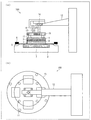
【課題】積層体から支持体を、より小さい力で、且つ、基板の破損及び変形を抑制して分離する。【解決手段】支持体分離装置100は、基板1と、接着層2と、光を吸収することによって変質する分離層3と、サポートプレート4と、をこの順で積層してなる積層体からサポートプレート4を分離し、積層体の一方の面を保持する保持部11と、保持部11を昇降させる昇降部12と、保持部11に掛かる力を一定に保つための調整部13とを備える。【選択図】図1A support is separated from a laminated body with a smaller force while suppressing breakage and deformation of the substrate. A support separating apparatus (100) supports a substrate (1), an adhesive layer (2), a separation layer (3) that is altered by absorbing light, and a support plate (4) stacked in this order. The holding part 11 which isolate | separates the plate 4 and hold | maintains one surface of a laminated body, the raising / lowering part 12 which raises / lowers the holding part 11, and the adjustment part 13 for keeping the force applied to the holding part 11 constant are provided. [Selection] Figure 1
Description
本発明は、積層体から支持体を分離する支持体分離装置及び支持体分離方法に関する。 The present invention relates to a support separating apparatus and a support separating method for separating a support from a laminate.
近年、ICカード、携帯電話などの電子機器の薄型化、小型化、軽量化などが要求されている。これらの要求を満たすためには、組み込まれる半導体チップについても薄型の半導体チップを使用しなければならない。このため、半導体チップの基となるウエハ基板の厚さ(膜厚)は現状では125μm〜150μmであるが、次世代のチップ用には25μm〜50μmにしなければならないといわれている。したがって、上記の膜厚のウエハ基板を得るためには、ウエハ基板の薄板化工程が必要不可欠である。 In recent years, electronic devices such as IC cards and mobile phones have been required to be thinner, smaller, and lighter. In order to satisfy these requirements, a thin semiconductor chip must be used as a semiconductor chip to be incorporated. For this reason, the thickness (film thickness) of the wafer substrate on which the semiconductor chip is based is currently 125 μm to 150 μm, but it is said that it must be 25 μm to 50 μm for the next generation chip. Therefore, in order to obtain a wafer substrate having the above film thickness, a wafer substrate thinning step is indispensable.
ウエハ基板は、薄板化により強度が低下するので、薄板化したウエハ基板の破損を防ぐために、製造プロセス中は、ウエハ基板にサポートプレートを貼り合わされた状態で自動搬送しながら、ウエハ基板上に回路等の構造物を実装する。そして、製造プロセス後に、ウエハ基板をサポートプレートから分離する。したがって、製造プロセス中は、ウエハ基板とサポートプレートとが強固に接着していることが好ましいが、製造プロセス後には、サポートプレートからウエハ基板を円滑に分離できることが好ましい。 Since the strength of the wafer substrate is reduced due to the thin plate, in order to prevent damage to the thinned wafer substrate, a circuit is placed on the wafer substrate while automatically supporting the support plate on the wafer substrate during the manufacturing process. Etc. are mounted. Then, after the manufacturing process, the wafer substrate is separated from the support plate. Therefore, it is preferable that the wafer substrate and the support plate are firmly bonded during the manufacturing process, but it is preferable that the wafer substrate can be smoothly separated from the support plate after the manufacturing process.
ウエハ基板とサポートプレートとを強固に接着した場合、接着材料によっては、ウエハ基板上に実装した構造物を破損させることなく、ウエハ基板からサポートプレートを分離することは困難である。したがって、製造プロセス中にはウエハ基板とサポートプレートとの強固な接着を実現しつつ、製造プロセス後にはウエハ基板上に実装した素子を破損させることなく分離するという、非常に困難な仮止め技術の開発が求められている。 When the wafer substrate and the support plate are firmly bonded, depending on the adhesive material, it is difficult to separate the support plate from the wafer substrate without damaging the structure mounted on the wafer substrate. Therefore, it is a very difficult temporary fixing technology that realizes strong adhesion between the wafer substrate and the support plate during the manufacturing process and separates the elements mounted on the wafer substrate without damaging them after the manufacturing process. Development is required.
仮止め技術として、例えば、ウエハ基板及びサポートプレートを接着する接着層とサポートプレートとの間に、光を照射することにより変質する分離層を予め設けておいてもよい。分離層に光を照射して当該分離層を変質させた後、ウエハ基板とサポートプレートとが接着した積層体に力を加えることにより、サポートプレートとウエハ基板との分離を行うことができる。 As the temporary fixing technique, for example, a separation layer that is altered by irradiating light may be provided in advance between the support layer and the adhesive layer that bonds the wafer substrate and the support plate. After the separation layer is irradiated with light to alter the separation layer, the support plate and the wafer substrate can be separated by applying a force to the laminated body in which the wafer substrate and the support plate are bonded.
ここで、特許文献1には、支持板を吸着する吸着手段を備え、支持板が貼着された基板から、当該支持板を剥離する剥離装置が記載されている。 Here, Patent Document 1 describes a peeling device that includes a suction unit that sucks a support plate and peels the support plate from a substrate on which the support plate is attached.
また、特許文献2には、吸着シートに液体を介在させて吸着保持されたガラス基板を該吸着シートから剥離する剥離手段を備えたガラス基板剥離装置が記載されている。
Further,
しかしながら、接着層を介して接着した支持体と基板との分離を行うとき、変質した分離層は領域によって変質度合いに相違がある。そのため、支持体を垂直に引き上げるだけでは、支持体を好適に分離することができない、あるいは、基板が破損又は変形するおそれがある。 However, when the substrate and the substrate bonded via the adhesive layer are separated, the altered separation layer has a different degree of alteration depending on the region. For this reason, the support cannot be separated properly only by pulling the support vertically, or the substrate may be damaged or deformed.
本発明に係る支持体分離装置及び支持体分離方法は、上記課題に鑑みてなされたものであり、積層体から支持体を、より小さい力で、且つ、基板の破損及び変形を抑制して分離することを目的とする。 The support body separating apparatus and the support body separating method according to the present invention have been made in view of the above problems, and separate the support body from the laminated body with a smaller force while suppressing breakage and deformation of the substrate. The purpose is to do.
本発明に係る支持体分離装置は、上記課題を解決するために、基板と、接着層と、光を吸収することによって変質する分離層と、支持体と、をこの順で積層してなる積層体から上記支持体を分離する支持体分離装置であって、上記積層体の一方の面を保持する保持部と、上記保持部を昇降させる昇降部と、上記保持部に掛かる力を一定に保つための調整部と、を備えることを特徴としている。 In order to solve the above problems, a support separating apparatus according to the present invention is a laminate in which a substrate, an adhesive layer, a separation layer that is altered by absorbing light, and a support are laminated in this order. A support separating apparatus for separating the support from a body, the holding unit holding one surface of the laminated body, a lifting unit for moving the holding unit up and down, and a force applied to the holding unit are kept constant. And an adjusting unit.
本発明に係る支持体分離方法は、基板と、接着層と、光を吸収することによって変質する分離層と、支持体と、をこの順で積層してなる積層体から上記支持体を分離する支持体分離方法であって、上記積層体を固定し、積層体の一方の面を、掛かる力が一定に保たれるように調整しながら保持して昇降させることを特徴としている。 The method for separating a support according to the present invention separates the support from a laminate obtained by laminating a substrate, an adhesive layer, a separation layer that is altered by absorbing light, and a support in this order. A method of separating a support, characterized in that the laminate is fixed, and one surface of the laminate is lifted and lowered while being adjusted so that the applied force is kept constant.
本発明に係る支持体分離装置及び支持体分離方法は、積層体から支持体を、より小さい力で、且つ、基板の破損及び変形を抑制して分離することができるという効果を奏する。 The support body separating apparatus and the support body separating method according to the present invention have an effect that the support body can be separated from the laminated body with a smaller force while suppressing breakage and deformation of the substrate.
以下、図1を用いて、本発明の実施の一形態について説明する。図1は、本発明の一実施形態に係る支持体分離装置100の概略の構成を示す図であり、(a)は側面図、(b)は上面図である。
Hereinafter, an embodiment of the present invention will be described with reference to FIG. FIG. 1 is a diagram showing a schematic configuration of a
〔支持体分離装置100〕
本実施形態に係る支持体分離装置100は、図1の(a)に示すように、ポーラス部7、ステージ8、保持部11、昇降部12、調整部13、検知部14、プレート部15及びストッパー16を有している。
[Support Separator 100]
As shown in FIG. 1A, the
支持体分離装置100は、基板1と、接着層2と、光を吸収することによって変質する分離層3と、サポートプレート(支持体)4と、をこの順で積層してなる積層体からサポートプレート4を分離するための装置である。また、支持体分離装置100が分離層3に光を照射する光照射手段を備え、支持体分離装置100に搭載した状態で分離層3を変質させた後、積層体からサポートプレート4を分離してもよく、あるいは、支持体分離装置100の外部で分離層3を変質させた後、支持体分離装置100に積層体を搬送し、積層体からサポートプレート4を分離してもよい。
The support
(基板1)
基板1は、接着層2を介してサポートプレート4に貼り付けられる。そして、基板1は、サポートプレート4に支持された状態で、薄化、実装等のプロセスに供され得る。基板1としては、シリコンウエハ基板に限定されず、セラミックス基板、薄いフィルム基板、フレキシブル基板等の任意の基板を使用することができる。
(Substrate 1)
The substrate 1 is attached to the support plate 4 via the
(サポートプレート4)
サポートプレート(支持体)4は、基板1を支持する支持体であり、接着層2を介して、基板1に貼り付けられる。そのため、サポートプレート4としては、基板1の薄化、搬送、実装等のプロセス時に、基板1の破損又は変形を防ぐために必要な強度を有していればよい。以上の観点から、サポートプレート4としては、ガラス、シリコン、アクリル系樹脂からなるもの等が挙げられる。
(Support plate 4)
The support plate (support) 4 is a support that supports the substrate 1, and is attached to the substrate 1 via the
(接着層2)
接着層2は、基板1とサポートプレート4とを貼り合わせるものであり、基板1に接着剤を塗布することによって形成される。基板1又はサポートプレート4への接着剤の塗布方法としては、特に限定されないが、例えば、スピンコート、ディッピング、ローラーブレード、スプレー塗布、スリット塗布等の方法が挙げられる。なお、本実施形態においては、基板に接着層を形成しているが、これに限定されず、支持体に接着層を形成してもよい。
(Adhesive layer 2)
The
接着層2を形成する接着剤としては、特に限定されず用いることができるが、加熱することによって熱流動性が向上する熱可塑性の接着材料が好ましい。熱可塑性の接着材料としては、例えば、アクリル系樹脂、スチレン系樹脂、マレイミド系樹脂、炭化水素系樹脂、エラストマー等が挙げられる。
The adhesive forming the
接着層2の厚さは、貼り合わせの対象となる基板1及びサポートプレート4の種類、接着後に施される基板1に施される処理等に応じて適宜設定することが可能であるが、5〜300μmであることが好ましく、10〜200μmであることがより好ましい。
The thickness of the
(分離層3)
分離層3は、光を照射することによって変質する層である。分離層3は、基板1とサポートプレート4との間に形成されている。そのため、基板1の薄化、搬送、実装等のプロセス後に光を分離層3に照射することで、容易に基板1とサポートプレート4とを分離することができる。
(Separation layer 3)
The
本明細書において、分離層3が「変質する」とは、分離層3をわずかな外力を受けて破壊され得る状態、又は分離層3と接する層との接着力が低下した状態にさせる現象を意味する。また、分離層3の変質は、吸収した光のエネルギーによる(発熱性又は非発熱性の)分解、架橋、立体配置の変化又は官能基の解離(そして、これらにともなう分離層3の硬化、脱ガス、収縮又は膨張)等であり得る。
In the present specification, the “deterioration” of the
また、分離層3として、プラズマCVD法により形成した無機膜または有機膜を用いてもよい。無機膜としては、例えば、金属膜を用いることができる。また、有機膜としては、フルオロカーボン膜を用いることができる。このような反応膜は、例えば、サポートプレート4上にプラズマCVD法により形成することができる。
Further, as the
分離層3に照射する光としては、分離層3が吸収可能な波長に応じて、例えば、YAGレーザ、リビーレーザ、ガラスレーザ、YVO4レーザ、LDレーザ、ファイバーレーザー等の固体レーザ、色素レーザ等の液体レーザ、CO2レーザ、エキシマレーザ、Arレーザ、He−Neレーザ等の気体レーザ、半導体レーザ、自由電子レーザ等のレーザ光、または、非レーザ光を適宜用いればよい。分離層3に吸収されるべき光の波長としては、これに限定されるものではないが、例えば、600nm以下の波長の光であり得る。
The light irradiating the
分離層3は、例えば光等によって分解される光吸収剤を含んでいてもよい。光吸収剤としては、例えば、グラファイト粉、鉄、アルミニウム、銅、ニッケル、コバルト、マンガン、クロム、亜鉛、テルルなどの微粒子金属粉末、黒色酸化チタンなどの金属酸化物粉末、カーボンブラック、または芳香族ジアミノ系金属錯体、脂肪族ジアミン系金属錯体、芳香族ジチオール系金属錯体、メルカプトフェノール系金属錯体、スクアリリウム系化合物、シアニン系色素、メチン系色素、ナフトキノン系色素、アントラキノン系色素などの染料もしくは顔料を用いることができる。このような分離層3は、例えば、バインダー樹脂と混合して、サポートプレート4上に塗布することによって形成することができる。また、光吸収基を有する樹脂を分離層3として用いることもできる。
The
(ダイシングテープ5)
ダイシングテープ5は、基板1の強度を補強するために基板1の片面に接着される。本実施形態において、積層体における基板1は、その外周にダイシングフレーム6が取り付けられたダイシングテープ5に貼着されている。
(Dicing tape 5)
The dicing
ダイシングテープ5としては、例えばベースフィルムに粘着層が形成された構成のダイシングテープを用いることができる。ベースフィルムとしては、例えば、PVC(ポリ塩化ビニル)、ポリオレフィン又はポリプロピレン等の樹脂フィルムを用いることができる。ダイシングテープ5の外径は基板1の外径よりも大きく、これらを貼り合わせると基板1の外縁部分にダイシングテープ5の一部が露出した状態になっている。
As the dicing
ダイシングテープ5の露出面のさらに外周には、ダイシングテープ5の撓みを防止するためのダイシングフレーム6が取り付けられている。すなわち、ダイシングテープ5の外縁部分では、ダイシングフレーム6が露出した状態になっている。ダイシングフレーム6としては、例えば、アルミニウム等の金属製のダイシングフレーム、ステンレススチール(SUS)等の合金製のダイシングフレーム、及び樹脂製のダイシングフレームが挙げられる。樹脂製のダイシングフレームとしては、例えば、信越ポリマー株式会社製又は株式会社ディスコ製の樹脂製ダイシングフレーム等が挙げられる。
A
ダイシングフレーム6として、金属製又は合金製のダイシングフレームを用いれば、剛性があり、ひずみにくい上に安価であるが、樹脂製のダイシングフレームと比較すると重いため、搬送時に作業者又は搬送ロボットに負担が掛かる。近年、平坦で剛性のある樹脂製のダイシングフレームが開発されており、従来広く用いられている金属製又は合金製のダイシングフレームと比較して軽量であるという利点がある。樹脂製のダイシングフレームは、軽量であるため搬送が容易であり、さらに金属製のフレームカセットに出し入れするときに、摩擦による発塵が少ないという利点がある。
If a dicing frame made of metal or alloy is used as the
以下、支持体分離装置100の各構成について説明する。
Hereinafter, each structure of the support
(ポーラス部7)
ポーラス部7は、ステージ8に設けられた多孔性部分をいう。ポーラス部7上に積層体が位置するように、ダイシングテープ5を貼着した積層体がステージ8に載置される。これにより、ポーラス部7を介してダイシングテープ5を貼着した積層体を吸引することができ、ステージ8上に積層体を好適に固定することができる。ポーラス部7を介してステージ8上に積層体を固定することにより、サポートプレート4を保持する保持部11を昇降部12により上昇させた場合であっても、積層体が上昇することを防止することができる。よって、サポートプレート4を保持する保持部11を昇降させることで、ステージ上に固定された積層体からサポートプレート4を分離することができる。
(Porous part 7)
The porous part 7 refers to a porous part provided on the
(保持部11)
保持部11は、積層体の一方の面を保持する吸着パッドである。本実施形態では、保持部11は、積層体におけるサポートプレート4の分離層3が設けられている面とは反対側の面を保持する。保持部11は、両端に開口部と内部に中空部とを備え、一方の開口部がサポートプレート4と接触し、もう一方の開口部は、吸引手段(図示せず)と接続している。そのため、吸引手段が吸引することで、サポートプレート4は保持部11に吸引されて保持される。なお、保持部11は、本実施形態のようにサポートプレート4を吸引して保持する形態に限定されず、例えば、サポートプレート4を把持して保持する構成であってもよい。
(Holding part 11)
The holding
図1の(b)に示すように、保持部11は、円形状のプレート部15に設けられており、プレート部15の中心から等距離に4つの保持部11がそれぞれ2組設けられている。保持するサポートプレート4の大きさに応じて、使用される保持部11が異なっており、例えば、半径が小さいサポートプレート4を保持するときは、内側の4つの保持部11を使用し、半径が大きいサポートプレート4を保持するときは、外側の4つの保持部11を使用する。本実施形態では、外側の4つの保持部を使用する場合を例に挙げている。
As shown in FIG. 1B, the holding
また、プレート部15の中心から等距離に4つ一組の保持部11が、それぞれ等間隔で設けられているため、保持部11は偏りなくサポートプレート4を保持することができる。なお、プレート部15の中心から等距離に配置される保持部11は、4つに限定されず、任意の数であってもよい。
In addition, since the set of four holding
また、本実施形態において、外側の保持部11の中心(保持部11の開口部の中心)は、プレート部15の外周近傍にあることが好ましい。外側の4つの保持部11の中心は、プレート部15の中心から伸びる線分であって、プレート部15の半径の8割以上の長さにあたる線分が形成する円の円周上に位置することがより好ましい。さらに、外側の4つの保持部11の中心は、プレート部15の半径の9割以上、略10割以下の長さにあたる線分が形成する円の円周上に位置することがさらに好ましい。外側の保持部11の中心が、プレート部15の外周近傍にあることにより、サポートプレート4の全体に均等に力が掛かりやすくなり、積層体からサポートプレート4を分離しやすくなる。
In the present embodiment, the center of the outer holding portion 11 (the center of the opening of the holding portion 11) is preferably in the vicinity of the outer periphery of the
また、本実施形態において、プレート部15の形状とサポートプレート4の形状は、ほぼ同じ(合同)であることが好ましく、プレート部15の半径とサポートプレート4の半径は、ほぼ同じであることがより好ましい。
In the present embodiment, the shape of the
4つ一組の保持部11を吸引手段と接続して、当該吸引手段により吸引してサポートプレート4を吸引保持する場合、4つ一組の保持部11の吸引力を合計で70kPa以上、100kPa以下とすることが好ましく、80kPa以上、90kPa以下とすることがさらに好ましい。これにより、保持部11はサポートプレート4を好適に吸引保持することができる。なお、保持部11がサポートプレート4を偏りなく保持するためには、すべての保持部11の吸引力を互いに等しくすることが好ましい。
When the support unit 4 is sucked and held by connecting a set of four holding
(昇降部12)
昇降部12は、保持部11を昇降させるためのものである。サポートプレート4を保持する保持部11を昇降させることにより、基板1とサポートプレート4とを分離することができる。
(Elevating part 12)
The elevating
光を照射することにより変質した分離層3は、わずかな外力を与えることにより破壊され得る状態、又は分離層3と接する層(接着層2)との接着力が低下した状態となっている。そのため、積層体をステージ8上に固定した状態でサポートプレート4を保持する保持部11を上昇させることにより、積層体からサポートプレート4を容易に分離することができる。
The
積層体をステージ8上に固定した状態でサポートプレート4を保持する保持部11を上昇させる速度としては、1mm/秒以上、2mm/秒以下であることが好ましい。これにより、サポートプレート4を徐々に分離することができ、基板1又はサポートプレート4に過度な力が掛かることがない。また、サポートプレート4を保持したまま、保持部11を合計で20mm程度引き上げた場合、積層体からサポートプレート4は通常、分離している。よって、保持部11を合計で20mm程度引き上げた後、保持部11を上昇させる速度を上げても基板1に過度な力が掛からない。
The speed at which the holding
(調整部13)
調整部13は、プレート部15に取り付けられており、保持部11に掛かる力を一定に保つためのものである。これにより、保持部11が保持する積層体に過度な力が掛かることを抑制し、基板1の破損、変形等を防止することができる。
(Adjustment unit 13)
The adjustment unit 13 is attached to the
本実施形態において、調整部13は、保持部11に対して可動するジョイントを備えている。また、ジョイントは、可動するときの軌跡が、積層体の面と平行又は垂直になるような弧又は円である。ジョイントがプレート部15に設けられた保持部11に対して自由に可動することにより、保持部11に掛かる力を一定に保つことができる。
In the present embodiment, the adjustment unit 13 includes a joint that is movable with respect to the holding
可動するジョイントの軌跡が、積層体の面と平行になるような弧又は円である場合、保持部11及び保持部11が保持するサポートプレート4が積層体の面と平行になるような弧又は円の軌跡を描く。
When the trajectory of the movable joint is an arc or a circle that is parallel to the surface of the laminate, the holding
可動するジョイントの軌跡が、積層体の面と垂直になるような弧である場合とは、可動するジョイントが描く弧(弧の延長線も含む)の或る接線が積層体の面と垂直に交わることをいう。 When the trajectory of the movable joint is an arc that is perpendicular to the plane of the stack, a certain tangent of the arc drawn by the movable joint (including the arc extension line) is perpendicular to the plane of the stack. Saying to cross.
ジョイントとしては、保持部11に対して可動するものであれば限定されないが、例えば、フローティングジョイント、ユニバーサルジョイント等が挙げられる。これらジョイントを調整部13として用いることにより、保持部11がサポートプレート4を保持している場合、保持部11がサポートプレート4とともに動作する。よって、保持部11が保持するサポートプレート4の全体に均等に力が掛かり、接着層2との接着が弱い部分の分離層3から接着層2と剥離していく、分離層3との接着が弱い部分のサポートプレート4から分離層3と剥離していく、あるいは、破壊されやすい部分の分離層3から破壊されて、積層体からサポートプレート4が分離されていく。
Although it will not be limited if it is movable with respect to the holding |
保持部11がサポートプレート4を保持するとき、ステージ8のポーラス部7に積層体を固定した状態で、保持部11を傾斜させてもよい。これにより、固定した積層体に対してサポートプレート4を傾斜させることができる。サポートプレート4を傾斜させることにより、積層体からサポートプレート4を分離しやすくなる。
When the holding
本実施形態に係る支持体分離装置100では、保持部11が必要以上に傾斜しないように、係止手段としてストッパー16が設けられている。このとき、保持部11が必要以上に傾斜しようとすると、ストッパー16と調整部13又はプレート部15とが接触してプレート部15がそれ以上傾斜しない。よって、基板1又はサポートプレート4に過度な力が掛かることを防止することができる。
In the
さらに、固定した積層体に対してサポートプレート4を傾斜させる場合、サポートプレート4における最も高い位置とサポートプレート4における最も低い位置との高低差が1cm以下になるようにストッパー16を設けることが好ましい。当該高低差を1cm以下とすることで、基板1又はサポートプレート4に過度な力が掛かることがなく、基板1又はサポートプレート4の破損又は変形を防止することができる。
Furthermore, when the support plate 4 is inclined with respect to the fixed laminate, it is preferable to provide the
(検知部14)
検知部14は、昇降部12に掛かる力を検知するためのものである。そのため、検知部14は、昇降部12に過度な力が掛かっているか否か、つまり、保持部11が保持する積層体に過度な力が掛かっているか否かを検知するようになっている。よって、保持部11が保持する積層体に過度な力が掛かるおそれがあるときは、例えば、保持部11がサポートプレート4の保持を解除する、あるいは、昇降部12が保持部11の上昇を停止する。これにより、保持部11が保持する積層体に過度な力が掛かることを抑制し、基板1の破損、変形等を好適に防止することができる。なお、本発明に係る支持体分離装置が備える検知部としては、例えば、ロードセル等を用いることができる。
(Detector 14)
The
また、支持体分離装置100は、検知部14による検知結果が予め設定された閾値以上であるときに、支持体分離処理を中断する制御部を有していてもよい。支持体分離処理を中断する処理としては、例えば、保持部11による積層体の保持の解消、又は、昇降部12による保持部11の上昇の停止等が挙げられる。これにより、保持部11が保持する積層体に過度な力が掛かったときに、制御部が自動的に支持体分離処理を中断し、基板1の破損、変形等をより好適に防止することができる。
Moreover, the support
予め設定される閾値としては、基板1の破損、変形等が生じない値であれば限定されないが、2.0Kgf以上、7.0Kgf以下であることが好ましく、3.0Kgf以上、5.0Kgf以下であることがより好ましい。これにより、分離層3が十分に変質している場合、閾値未満の力が積層体に掛かったときであっても、積層体からサポートプレート4を分離することができる。さらに、上記閾値程度の力が積層体に掛かった場合では、基板1の破損、変形等が生じない。よって、基板1の破損、変形等が生じる前に、支持体分離処理を中断することができる。
The threshold value set in advance is not limited as long as the substrate 1 is not damaged or deformed, but is preferably 2.0 kgf or more and 7.0 kgf or less, preferably 3.0 kgf or more and 5.0 kgf or less. It is more preferable that Thereby, when the
さらに、制御部は、支持体分離処理を中止した後に再度、サポートプレート4の分離を開始するように支持体分離装置100を制御してもよい。例えば、制御部は、保持部11による積層体の保持を解消した場合、再度、保持部11が積層体を保持するように支持体分離装置100を制御し、あるいは、昇降部12による保持部11の上昇を停止した場合、再度、昇降部12が保持部11を上昇させるように支持体分離装置100を制御する。これにより、支持体分離装置100にサポートプレート4の分離を再度、自動的に行わせることができる。なお、サポートプレート4の分離を再度開始し、検知部14による検知結果が予め設定された閾値以上を再度超えてしまった場合には、制御部は支持体分離処理を中断する。
Further, the control unit may control the
さらに、制御部は、同じ積層体に対して閾値以上の力が3回断続的に加わった場合に、支持体分離処理を終了するように支持体分離装置100を制御してもよい。3回断続的に閾値以上の力を加えてもサポートプレート4を分離することができない場合、同一条件での支持体分離処理を繰り返しても、それ以降、サポートプレート4を好適に分離することができる可能性は少ない。そのため、予め定めた回数(本実施形態では3回)に達してもサポートプレート4を分離することができない場合に、制御部が支持体分離処理を終了するように支持体分離装置100を制御することで、不要な処理を繰り返すことを防止することができる。なお、制御部が支持体分離処理を終了するまでに同じ積層体に対して閾値以上の力を加える回数は、3回に限定されず、ユーザが当該回数を適宜定めることができる。
Further, the control unit may control the
〔支持体分離装置100の動作フロー〕
以下、本発明の一実施形態に係る支持体分離装置100の動作フローについて説明する。まず、光を照射して分離層3を変質させた積層体をステージ8に設置する。このとき、ポーラス部7を介してダイシングテープ5を貼着した積層体を吸引することができ、ステージ8上に積層体を固定することができる。
[Operation Flow of Support Separator 100]
Hereinafter, an operation flow of the
次に、保持部11が、積層体におけるサポートプレート4の分離層3が設けられている面と反対側の面を保持する。本実施形態では、保持部11に接続した吸引手段を用いて、サポートプレート4を保持部11に吸引させて保持する。
Next, the holding
そして、昇降部12を上昇させることにより、サポートプレート4を保持する保持部11を上昇させる。これにより、積層体をステージ8上に固定した状態で、サポートプレート4(積層体の一方の面)を上昇させることができる。
And the raising
サポートプレート4を上昇させるときに積層体に掛かる力が、予め定められた閾値未満の場合、支持体分離処理を中断することなく、サポートプレート4を上昇させる。よって、積層体からサポートプレート4を分離することができる。 If the force applied to the laminate when raising the support plate 4 is less than a predetermined threshold, the support plate 4 is raised without interrupting the support separation process. Therefore, the support plate 4 can be separated from the laminate.
一方、サポートプレート4を上昇させるときに積層体に掛かる力が、予め定められた閾値以上の場合、支持体分離処理を中断する。その後、再度、同一の積層体に対して支持体分離処理を行う。そして、積層体に対して閾値以上の力が予め定めた回数(例えば、3回)、断続的に加わった場合に、支持体分離処理を終了する。 On the other hand, when the force applied to the laminate when raising the support plate 4 is equal to or greater than a predetermined threshold, the support separation process is interrupted. Thereafter, the support separation process is performed again on the same laminate. When the force equal to or greater than the threshold value is intermittently applied to the laminated body for a predetermined number of times (for example, three times), the support separation process is terminated.
支持体分離処理を終了したにもかかわらず、サポートプレート4を基板1から分離することができなかった積層体については、再度、サポートプレート4側から光を照射して分離層3をさらに変質させてもよい。これにより、同じ積層体について再度、支持体分離処理を施した場合に、積層体からサポートプレート4を分離することがより容易となる。
For the laminated body in which the support plate 4 could not be separated from the substrate 1 even after the support separation process was completed, the
本実施形態において、支持体分離装置100は、積層体の一方の面を保持する保持部11と、昇降部12により保持部11を昇降させたときに、保持部11に掛かる力を一定に保つための調整部13とを備えている。そのため、保持部11が保持するサポートプレート4の全体に均等に力が掛かり、接着層2との接着が弱い部分の分離層3から接着層2と剥離していく、分離層3との接着が弱い部分のサポートプレート4から分離層3と剥離をしていく、あるいは、破壊されやすい部分の分離層3から破壊されて、積層体からサポートプレート4が分離されていく。したがって、基板1又はサポートプレート4が破損、変形することなく、積層体からサポートプレート4を、より小さい力で、且つ、基板の破損及び変形を抑制して分離することができる。
In this embodiment, the
本実施形態に係る支持体分離装置100を用いてサポートプレート4を分離した後、サポートプレート4を保持する保持部11は、例えば、サポートプレート4に付着した分離層3を除去する除去部(図示せず)、又は、分離層3を除去する分離層除去装置(図示せず)にサポートプレート4を搬送してもよい。
After the support plate 4 is separated using the
なお、本実施形態では、支持体分離装置100を用いた支持体分離方法について説明したが、本発明はこれに限定されず、他の支持体分離装置を用いた支持体分離方法、及び、支持体分離装置を用いることなく支持体を分離する場合についても、本発明に係る支持体分離方法に包含される。
In this embodiment, the support separating method using the
以下に実施例を示し、本発明の実施の形態についてさらに詳しく説明する。もちろん、本発明は以下の実施例に限定されるものではなく、細部については様々な態様が可能であることはいうまでもない。さらに、本発明は上述した実施形態に限定されるものではなく、請求項に示した範囲で種々の変更が可能であり、それぞれ開示された技術的手段を適宜組み合わせて得られる実施形態についても本発明の技術的範囲に含まれる。また、本明細書中に記載された文献の全てが参考として援用される。 Examples will be shown below, and the embodiments of the present invention will be described in more detail. Of course, the present invention is not limited to the following examples, and it goes without saying that various aspects are possible in detail. Further, the present invention is not limited to the above-described embodiments, and various modifications can be made within the scope shown in the claims, and the present invention is also applied to the embodiments obtained by appropriately combining the disclosed technical means. It is included in the technical scope of the invention. Moreover, all the literatures described in this specification are used as reference.
〔実施例1〕
(積層体の作製)
実施例の積層体を次のようにして作製した。まず、流量400sccm、圧力700mTorr、高周波電力2500W及び成膜温度240℃の条件下において、反応ガスとしてC4F8を使用したCVD法により、分離層であるフルオロカーボン膜(厚さ1μm)を支持体(12インチガラスサポートプレート、厚さ700μm)上に形成した。次に、12インチシリコンウエハには接着剤組成物であるTZNR−A3007t(東京応化工業株式会社製)をスピン塗布して、100℃、160℃、200℃で各3分加熱して接着層を形成した(膜厚50μm)。そして、真空下220℃、4000Kgの条件で3分間、接着層及び分離層を介してシリコンウエハとサポートプレートとの貼り合せを行ない、積層体を作製した。
[Example 1]
(Production of laminate)
The laminated body of the Example was produced as follows. First, under the conditions of a flow rate of 400 sccm, a pressure of 700 mTorr, a high frequency power of 2500 W, and a film forming temperature of 240 ° C., a fluorocarbon film (thickness 1 μm) as a separation layer is supported by a CVD method using C 4 F 8 as a reaction gas. (12-inch glass support plate, thickness 700 μm). Next, TZNR-A3007t (manufactured by Tokyo Ohka Kogyo Co., Ltd.), which is an adhesive composition, is spin-coated on a 12-inch silicon wafer and heated at 100 ° C., 160 ° C., and 200 ° C. for 3 minutes each to form an adhesive layer. Formed (film thickness 50 μm). Then, the silicon wafer and the support plate were bonded through an adhesive layer and a separation layer for 3 minutes under a condition of 220 ° C. and 4000 Kg under vacuum to produce a laminate.
(サポートプレートの分離)
上記作製条件により作製した積層体を、以下のような処理をした上で、サポートプレートがシリコンウエハから分離されるか否かについて評価した。
(Separation of support plate)
The laminated body produced under the above production conditions was subjected to the following treatment, and then evaluated whether or not the support plate was separated from the silicon wafer.
532nmの波長を有するパルスレーザを、積層体のサポートプレート側から分離層に向けて照射した。レーザ条件としては、電流が19A、照射速度が6,500mm/sec、パルス周波数が40kHz、照射ピッチが180μm、照射範囲がφ309mmであった。 A pulse laser having a wavelength of 532 nm was irradiated from the support plate side of the laminate toward the separation layer. As laser conditions, the current was 19 A, the irradiation speed was 6,500 mm / sec, the pulse frequency was 40 kHz, the irradiation pitch was 180 μm, and the irradiation range was φ309 mm.
上記条件でパルスレーザを照射した後、図1に示す支持体分離装置であって、調整部としてジョイントを備えた支持体分離装置を用いて、積層体からサポートプレートを分離した。支持体分離装置には、半径150mmのプレート部にその外周から10mmの位置に保持部として吸着パット(φ15mm)が4つ設けられており(吸着パットの中心は外周から2.5mmの位置にある)、サポートプレートを合計で90kPaの吸着力で当該吸着パットに吸着させた。そして、積層体をステージに固定した状態で、サポートプレートを吸着した吸着パットを1〜2mm/secの速さで引き上げた。このとき、保持部を上昇させる昇降部に掛かる力を検知部にて検知すると、0.3Kgfであった。その後、サポートプレートを吸着した吸着パッドを20mm引き上げ、ステージに固定した積層体からサポートプレートを分離した。 After irradiating the pulsed laser under the above conditions, the support plate was separated from the laminate using the support separating apparatus shown in FIG. 1 and having a joint as an adjusting portion. The support separating apparatus is provided with four suction pads (φ15 mm) as holding portions at a position 10 mm from the outer periphery of a plate portion having a radius of 150 mm (the center of the suction pad is located at a position 2.5 mm from the outer periphery). ), The support plate was adsorbed to the adsorption pad with a total adsorption force of 90 kPa. And the adsorption pad which adsorb | sucked the support plate was pulled up at the speed of 1-2 mm / sec in the state which fixed the laminated body to the stage. At this time, when the force applied to the elevating part that raises the holding part was detected by the detection part, it was 0.3 kgf. Then, the suction pad which adsorb | sucked the support plate was pulled up 20 mm, and the support plate was isolate | separated from the laminated body fixed to the stage.
〔比較例1〕
実施例1と同様の方法で積層体を作製し、かつ、同様の条件でレーザを照射した。
[Comparative Example 1]
A laminate was produced in the same manner as in Example 1, and the laser was irradiated under the same conditions.
実施例1と同様の条件でパルスレーザを照射した後、支持体分離装置を用いて、積層体からサポートプレートを分離した。本比較例にて用いる支持体分離装置は、保持部に掛かる力を一定に保つための調整部(ジョイント)が設けられておらず、保持部は昇降方向以外には移動しない。本比較例にて用いた支持体分離装置におけるプレート部と吸着パットについては、実施例1と同様である。 After irradiating with a pulse laser under the same conditions as in Example 1, the support plate was separated from the laminate using a support separation device. The support separating apparatus used in this comparative example is not provided with an adjustment unit (joint) for keeping the force applied to the holding unit constant, and the holding unit does not move except in the up-and-down direction. The plate part and the suction pad in the support separating apparatus used in this comparative example are the same as in Example 1.
まず、比較例に係る支持体分離装置を用いて、サポートプレートを合計で90kPaの吸着力で当該吸着パットに吸着させた。そして、積層体をステージに固定した状態で、サポートプレートを吸着した吸着パットを1〜2mm/secの速さで引き上げた。このとき、保持部を上昇させる昇降部に掛かる力を検知部にて検知すると、3.0Kgfであったが、シリコンウエハが割れてしまった。 First, the support plate was made to adsorb | suck to the said adsorption | suction pad by the adsorption force of 90 kPa in total using the support body separation apparatus which concerns on a comparative example. And the adsorption pad which adsorb | sucked the support plate was pulled up at the speed of 1-2 mm / sec in the state which fixed the laminated body to the stage. At this time, when the force applied to the elevating part that raises the holding part was detected by the detection part, it was 3.0 kgf, but the silicon wafer was broken.
実施例1では、比較例1よりも昇降部に掛かる力がより小さい状態で積層体からサポートプレートを分離することができた。一方、比較例1では、実施例1よりも昇降部に掛かる力がより大きく、その結果、積層体からサポートプレートを分離する際に、シリコンウエハが割れてしまった。以上により、実施例1に係る支持体分離装置を用いた場合、より昇降部に力が掛からず、積層体からサポートプレートをより安定的に分離することができた。 In Example 1, it was possible to separate the support plate from the laminate in a state where the force applied to the elevating part was smaller than that in Comparative Example 1. On the other hand, in Comparative Example 1, the force applied to the elevating part was larger than that in Example 1, and as a result, the silicon wafer was broken when the support plate was separated from the laminate. As described above, when the support body separating apparatus according to Example 1 was used, a force was not applied to the elevating part, and the support plate could be more stably separated from the laminate.
本発明に係る支持体分離装置及び支持体分離方法は、例えば、微細化された半導体装置の製造工程において広範に利用することができる。 The support body separating apparatus and the support body separating method according to the present invention can be widely used, for example, in the manufacturing process of a miniaturized semiconductor device.
1 基板
2 接着層
3 分離層
4 サポートプレート(支持体)
5 ダイシングテープ
6 ダイシングフレーム
7 ポーラス部
8 ステージ
11 保持部
12 昇降部
13 調整部
14 検知部
15 プレート部
16 ストッパー
100 支持体分離装置
1
DESCRIPTION OF
Claims (9)
上記積層体の一方の面を保持する保持部と、
上記保持部を昇降させる昇降部と、
上記保持部に掛かる力を一定に保つための調整部と、を備えることを特徴とする支持体分離装置。 A support separating apparatus for separating the support from a laminate formed by laminating a substrate, an adhesive layer, a separation layer that is altered by absorbing light, and a support in this order,
A holding part for holding one surface of the laminate;
An elevating part for raising and lowering the holding part;
And a adjusting unit for keeping the force applied to the holding unit constant.
上記積層体を固定し、積層体の一方の面を、掛かる力が一定に保たれるように調整しながら保持して昇降させることを特徴とする支持体分離方法。 A support separating method for separating the support from a laminate obtained by laminating a substrate, an adhesive layer, a separation layer that is altered by absorbing light, and a support in this order,
A method of separating a support, comprising: fixing the laminate, and holding and raising one side of the laminate while adjusting the applied force so as to be kept constant.
Priority Applications (4)
| Application Number | Priority Date | Filing Date | Title |
|---|---|---|---|
| JP2013095969A JP5926700B2 (en) | 2013-04-30 | 2013-04-30 | Support body separating apparatus and support body separating method |
| US14/202,445 US9238357B2 (en) | 2013-04-30 | 2014-03-10 | Supporting member separation apparatus and supporting member separation method |
| TW103108148A TWI545685B (en) | 2013-04-30 | 2014-03-10 | Support body separation device and support body separation method |
| KR1020140028952A KR101625730B1 (en) | 2013-04-30 | 2014-03-12 | Supporting member separation apparatus and supporting member separation method |
Applications Claiming Priority (1)
| Application Number | Priority Date | Filing Date | Title |
|---|---|---|---|
| JP2013095969A JP5926700B2 (en) | 2013-04-30 | 2013-04-30 | Support body separating apparatus and support body separating method |
Publications (3)
| Publication Number | Publication Date |
|---|---|
| JP2014216632A true JP2014216632A (en) | 2014-11-17 |
| JP2014216632A5 JP2014216632A5 (en) | 2016-01-21 |
| JP5926700B2 JP5926700B2 (en) | 2016-05-25 |
Family
ID=51788240
Family Applications (1)
| Application Number | Title | Priority Date | Filing Date |
|---|---|---|---|
| JP2013095969A Active JP5926700B2 (en) | 2013-04-30 | 2013-04-30 | Support body separating apparatus and support body separating method |
Country Status (4)
| Country | Link |
|---|---|
| US (1) | US9238357B2 (en) |
| JP (1) | JP5926700B2 (en) |
| KR (1) | KR101625730B1 (en) |
| TW (1) | TWI545685B (en) |
Cited By (3)
| Publication number | Priority date | Publication date | Assignee | Title |
|---|---|---|---|---|
| JP2017147345A (en) * | 2016-02-17 | 2017-08-24 | 東京応化工業株式会社 | Support separation device and support separation method |
| KR20180002499A (en) | 2016-06-29 | 2018-01-08 | 도오꾜오까고오교 가부시끼가이샤 | A support separation apparatus, and a support separation method |
| JP6915191B1 (en) * | 2021-01-21 | 2021-08-04 | 信越エンジニアリング株式会社 | Work separation device and work separation method |
Families Citing this family (4)
| Publication number | Priority date | Publication date | Assignee | Title |
|---|---|---|---|---|
| JP6216727B2 (en) * | 2014-05-08 | 2017-10-18 | 東京応化工業株式会社 | Support separation method |
| CN106158691A (en) * | 2015-01-27 | 2016-11-23 | 精材科技股份有限公司 | Stripping device and method for stripping surface cover layer of chip package by using same |
| JP6695227B2 (en) * | 2016-07-19 | 2020-05-20 | 東京応化工業株式会社 | Support separation device and support separation method |
| CN113299576B (en) * | 2020-02-21 | 2022-11-22 | 济南晶正电子科技有限公司 | Mechanical film separating device |
Citations (6)
| Publication number | Priority date | Publication date | Assignee | Title |
|---|---|---|---|---|
| JP2004266052A (en) * | 2003-02-28 | 2004-09-24 | Canon Inc | Superposition device |
| JP2005191535A (en) * | 2003-12-01 | 2005-07-14 | Tokyo Ohka Kogyo Co Ltd | Pasting apparatus and pasting method |
| US7187162B2 (en) * | 2002-12-16 | 2007-03-06 | S.O.I.Tec Silicon On Insulator Technologies S.A. | Tools and methods for disuniting semiconductor wafers |
| JP2009289878A (en) * | 2008-05-28 | 2009-12-10 | Fujitsu Ltd | Apparatus and method for processing substrate |
| WO2013005589A1 (en) * | 2011-07-04 | 2013-01-10 | 旭硝子株式会社 | Method for peeling glass substrate, and apparatus for peeling glass substrate |
| US8360129B2 (en) * | 2009-08-31 | 2013-01-29 | Asahi Glass Company, Limited | Peeling device |
Family Cites Families (7)
| Publication number | Priority date | Publication date | Assignee | Title |
|---|---|---|---|---|
| JP2005057046A (en) * | 2003-08-04 | 2005-03-03 | Sekisui Chem Co Ltd | IC chip manufacturing method and IC chip manufacturing apparatus |
| JP4985513B2 (en) * | 2008-03-26 | 2012-07-25 | 富士通セミコンダクター株式会社 | Method and apparatus for peeling electronic parts |
| JP5210060B2 (en) | 2008-07-02 | 2013-06-12 | 東京応化工業株式会社 | Peeling apparatus and peeling method |
| KR101217749B1 (en) * | 2008-12-11 | 2013-01-02 | 디아이씨 가부시끼가이샤 | Curable resin composition and paint, and plastic molded product produced by laminating the same |
| JP5795199B2 (en) | 2011-06-16 | 2015-10-14 | 株式会社ダイヘン | Power converter and control method of power converter |
| US8858756B2 (en) * | 2011-10-31 | 2014-10-14 | Masahiro Lee | Ultrathin wafer debonding systems |
| JP5977710B2 (en) * | 2013-05-10 | 2016-08-24 | 東京エレクトロン株式会社 | Peeling apparatus, peeling system, peeling method, program, and computer storage medium |
-
2013
- 2013-04-30 JP JP2013095969A patent/JP5926700B2/en active Active
-
2014
- 2014-03-10 TW TW103108148A patent/TWI545685B/en active
- 2014-03-10 US US14/202,445 patent/US9238357B2/en active Active
- 2014-03-12 KR KR1020140028952A patent/KR101625730B1/en active Active
Patent Citations (6)
| Publication number | Priority date | Publication date | Assignee | Title |
|---|---|---|---|---|
| US7187162B2 (en) * | 2002-12-16 | 2007-03-06 | S.O.I.Tec Silicon On Insulator Technologies S.A. | Tools and methods for disuniting semiconductor wafers |
| JP2004266052A (en) * | 2003-02-28 | 2004-09-24 | Canon Inc | Superposition device |
| JP2005191535A (en) * | 2003-12-01 | 2005-07-14 | Tokyo Ohka Kogyo Co Ltd | Pasting apparatus and pasting method |
| JP2009289878A (en) * | 2008-05-28 | 2009-12-10 | Fujitsu Ltd | Apparatus and method for processing substrate |
| US8360129B2 (en) * | 2009-08-31 | 2013-01-29 | Asahi Glass Company, Limited | Peeling device |
| WO2013005589A1 (en) * | 2011-07-04 | 2013-01-10 | 旭硝子株式会社 | Method for peeling glass substrate, and apparatus for peeling glass substrate |
Cited By (8)
| Publication number | Priority date | Publication date | Assignee | Title |
|---|---|---|---|---|
| JP2017147345A (en) * | 2016-02-17 | 2017-08-24 | 東京応化工業株式会社 | Support separation device and support separation method |
| KR20180002499A (en) | 2016-06-29 | 2018-01-08 | 도오꾜오까고오교 가부시끼가이샤 | A support separation apparatus, and a support separation method |
| JP6915191B1 (en) * | 2021-01-21 | 2021-08-04 | 信越エンジニアリング株式会社 | Work separation device and work separation method |
| WO2022157885A1 (en) * | 2021-01-21 | 2022-07-28 | 信越エンジニアリング株式会社 | Workpiece separation device and workpiece separation method |
| KR20230005420A (en) * | 2021-01-21 | 2023-01-09 | 신에츠 엔지니어링 가부시키가이샤 | Work separation device and work separation method |
| CN115803851A (en) * | 2021-01-21 | 2023-03-14 | 信越工程株式会社 | Workpiece separation device and workpiece separation method |
| KR102543854B1 (en) | 2021-01-21 | 2023-06-14 | 신에츠 엔지니어링 가부시키가이샤 | Work separation device and work separation method |
| CN115803851B (en) * | 2021-01-21 | 2023-06-30 | 信越工程株式会社 | Workpiece separating device and workpiece separating method |
Also Published As
| Publication number | Publication date |
|---|---|
| KR101625730B1 (en) | 2016-06-13 |
| JP5926700B2 (en) | 2016-05-25 |
| US9238357B2 (en) | 2016-01-19 |
| KR20140130018A (en) | 2014-11-07 |
| US20140318714A1 (en) | 2014-10-30 |
| TW201448107A (en) | 2014-12-16 |
| TWI545685B (en) | 2016-08-11 |
Similar Documents
| Publication | Publication Date | Title |
|---|---|---|
| JP5926700B2 (en) | Support body separating apparatus and support body separating method | |
| JP5273791B2 (en) | Equipment for applying adhesive tape to substrates | |
| JP5253996B2 (en) | Work dividing method and tape expansion device | |
| JP6283573B2 (en) | Peeling apparatus, peeling system, peeling method, program, and computer storage medium | |
| JP6226596B2 (en) | Support separator | |
| CA2709626A1 (en) | Method and apparatus for removing a reversibly mounted device wafer from a carrier substrate | |
| CN107452596B (en) | Method for manufacturing element chip | |
| JP2015076570A (en) | Peeling apparatus, peeling system, peeling method, program, and computer storage medium | |
| JPWO2014157082A1 (en) | Pasting method | |
| JP2020024976A (en) | Protective member forming device | |
| US20110290415A1 (en) | Apparatus and method for detaping an adhesive layer from the surface of ultra thin wafers | |
| US10964597B2 (en) | Element chip manufacturing method | |
| JP6626413B2 (en) | Support separating method and substrate processing method | |
| JP2019186399A (en) | Adhesive tape peeling method and adhesive tape peeling device | |
| JP2005175207A (en) | Semiconductor device manufacturing method, grinding reinforcing member, and method of attaching the same | |
| KR101304282B1 (en) | debonding method of temporary bonded device wafer and carrier wafer | |
| JP6670190B2 (en) | Support separating apparatus and support separating method | |
| JP6612588B2 (en) | Support body separating apparatus and support body separating method | |
| CN113953133A (en) | Sheet and method for forming protective member | |
| KR101403850B1 (en) | System for holding large scale substrate | |
| JP6612648B2 (en) | Support body separating apparatus and support body separating method | |
| WO2015087763A1 (en) | Sealing sheet adhesion method | |
| JP2020053472A (en) | Method for manufacturing element chip | |
| JP2019160883A (en) | Method for manufacturing element chip | |
| JP2007088038A (en) | Re-sticking device and method therefor |
Legal Events
| Date | Code | Title | Description |
|---|---|---|---|
| A521 | Request for written amendment filed |
Free format text: JAPANESE INTERMEDIATE CODE: A523 Effective date: 20151126 |
|
| A621 | Written request for application examination |
Free format text: JAPANESE INTERMEDIATE CODE: A621 Effective date: 20151126 |
|
| A871 | Explanation of circumstances concerning accelerated examination |
Free format text: JAPANESE INTERMEDIATE CODE: A871 Effective date: 20151126 |
|
| A975 | Report on accelerated examination |
Free format text: JAPANESE INTERMEDIATE CODE: A971005 Effective date: 20160118 |
|
| A131 | Notification of reasons for refusal |
Free format text: JAPANESE INTERMEDIATE CODE: A131 Effective date: 20160126 |
|
| A521 | Request for written amendment filed |
Free format text: JAPANESE INTERMEDIATE CODE: A523 Effective date: 20160309 |
|
| TRDD | Decision of grant or rejection written | ||
| A01 | Written decision to grant a patent or to grant a registration (utility model) |
Free format text: JAPANESE INTERMEDIATE CODE: A01 Effective date: 20160419 |
|
| A61 | First payment of annual fees (during grant procedure) |
Free format text: JAPANESE INTERMEDIATE CODE: A61 Effective date: 20160422 |
|
| R150 | Certificate of patent or registration of utility model |
Ref document number: 5926700 Country of ref document: JP Free format text: JAPANESE INTERMEDIATE CODE: R150 |
|
| R250 | Receipt of annual fees |
Free format text: JAPANESE INTERMEDIATE CODE: R250 |
|
| S111 | Request for change of ownership or part of ownership |
Free format text: JAPANESE INTERMEDIATE CODE: R313111 |
|
| R350 | Written notification of registration of transfer |
Free format text: JAPANESE INTERMEDIATE CODE: R350 |
|
| R250 | Receipt of annual fees |
Free format text: JAPANESE INTERMEDIATE CODE: R250 |
|
| R250 | Receipt of annual fees |
Free format text: JAPANESE INTERMEDIATE CODE: R250 |