JP2014207626A - Aircraft communication method and aircraft communication system - Google Patents
Aircraft communication method and aircraft communication system Download PDFInfo
- Publication number
- JP2014207626A JP2014207626A JP2013085354A JP2013085354A JP2014207626A JP 2014207626 A JP2014207626 A JP 2014207626A JP 2013085354 A JP2013085354 A JP 2013085354A JP 2013085354 A JP2013085354 A JP 2013085354A JP 2014207626 A JP2014207626 A JP 2014207626A
- Authority
- JP
- Japan
- Prior art keywords
- aircraft
- station
- unit
- ground
- ground station
- Prior art date
- Legal status (The legal status is an assumption and is not a legal conclusion. Google has not performed a legal analysis and makes no representation as to the accuracy of the status listed.)
- Pending
Links
Images


Classifications
-
- H—ELECTRICITY
- H04—ELECTRIC COMMUNICATION TECHNIQUE
- H04B—TRANSMISSION
- H04B7/00—Radio transmission systems, i.e. using radiation field
- H04B7/14—Relay systems
- H04B7/15—Active relay systems
- H04B7/185—Space-based or airborne stations; Stations for satellite systems
- H04B7/18502—Airborne stations
- H04B7/18506—Communications with or from aircraft, i.e. aeronautical mobile service
Abstract
Description
本発明は、航空機通信技術に関し、特に、衛星を介さずに地上と航空機間で無線通信を行う航空機通信技術に関する。 The present invention relates to aircraft communication technology, and more particularly to aircraft communication technology for performing wireless communication between the ground and an aircraft without using a satellite.
衛星を介さずに地上局と航空機間で無線通信を行う航空機通信に関する技術としては、例えば、特許文献1および特許文献2に記載されたものがある。
特許文献1は、航空機と地上の送受信機との間に無線通信リンクを成立させるために、地上の送受信機の通信アンテナを指向制御することで航空機を追尾して通信状態を維持するシステムにおける発明で、航空機から衛星通信リンクを経由して取得する第1の位置情報と、航空機の管制あるいは警戒システムにおけるレーダ情報から取得する第2の位置情報に優先度を設定し、通信接続状態が切断されたと判定されたとき、優先度に従って位置情報を選択して所定時間後の航空機の位置を予測し、予測された航空機の位置に通信アンテナを指向させて航空機との通信状態を維持する技術が開示されている。
For example,
また、特許文献2には、飛行中の航空機と受信器との間に無線周波(RF)通信リンクを成立させるために、適応アンテナアレイを飛行中の航空機の方向に指向させるシステム及び方法に関する発明で、受信アンテナアレイパターンの主ローブを飛行中の航空機の方向に電子的にステアリングすると同時に、他の方向からの信号に対する受信器の感度を最小限に抑えることを目的とし、航空機追跡サービスなどの航空機追跡手段から航空機に関する航空機位置情報を受信し、飛行中の所定の飛行機について航空機位置ベクトルgを計算し、その位置ベクトルgに基づいてアンテナ重みベクトルwを発生させて適応アンテナアレイのアンテナ素子に提供し、受信ローブが飛行中の航空機に向けて指向されるようにする技術が開示されている。
背景技術で説明したような、通信会社以外の外部システム(航空管制システム、飛行運行計画、航空機追尾サービスなど)から航空情報(位置情報、航空機の無線機ID)を取得し、地上局から航空機に向けてビームフォームを行うことで航空機を追尾する公知例はあるが、通信会社内のシステムで完結しないという問題点があった。
通信会社外の航空機関係システムと連携する構成とせざるを得ないことにより、システム構成が多段になり設備使用費・システム管理費が高額になるため、よりシンプルな構成のシステムを必要としていた。
また、航空機の機内サービスとして無線LAN環境を提供出来ているが、航空機から外部へのアクセス方法として、衛星を介した通信が一般的である。高速無線LAN環境のサービスを提供するには、限りある衛星回線数を増強する必要があり、その増強分、高額な回線使用料を負担することになるため、衛星通信と比較して安価に構築でき、安定した回線品質がある地上局と航空機を接続する方法が必要とされていた。
Acquire aviation information (location information, aircraft radio ID) from external systems (air traffic control system, flight operation plan, aircraft tracking service, etc.) other than telecommunications companies, as described in Background Art, and transfer from ground station to aircraft Although there is a known example of tracking an aircraft by performing beam forming toward it, there is a problem that it is not completed by a system in a communication company.
Since it must be configured to cooperate with aircraft-related systems outside the telecommunications company, the system configuration becomes multi-stage and equipment use costs and system management costs become high, so a system with a simpler configuration is required.
In addition, although a wireless LAN environment can be provided as an in-flight service for an aircraft, communication via a satellite is generally used as an access method from the aircraft to the outside. In order to provide high-speed wireless LAN environment services, it is necessary to increase the number of limited satellite channels, and because of the increase, you will be charged an expensive line usage fee. There was a need for a way to connect an aircraft to a ground station that was capable of stable line quality.
上記課題を解決するために、本発明は、航空機と、航空機の飛行経路上に配置された複数の地上局と、複数の地上局と地上回線で接続され地上局を制御する制御局を少なくとも有する航空機通信システムにおいて、航空機は複数のアレイアンテナ部と複数のアレイアンテナ部がそれぞれ別の方向にビームを送信するように制御する制御部と、位置情報取得部と、ビームフォームを行うための情報を記憶する記憶部を有する無線装置部と航空機内の端末と無線信号を送受信する無線サービス部とを有し、航空機の記憶部に、複数の地上局の位置情報および、位置情報取得部が取得した航空機の位置情報を記憶しておき、航空機は複数の地上局の位置情報および航空機の位置情報に基づいて、少なくとも一つの地上局を選択し、該地上局に向けたビームを形成して送信し、地上局もまた、アレイアンテナ部とアレイアンテナ部が送信するビームを制御する制御部と、ビームフォームを行うための情報を記憶する記憶部を有する無線装置部と、を有し、航空機および地上局の双方がビームフォーミングを行うことにより通信を継続することを特徴とする。 In order to solve the above-described problems, the present invention includes at least an aircraft, a plurality of ground stations arranged on a flight path of the aircraft, and a control station connected to the plurality of ground stations through a ground line and controlling the ground station. In an aircraft communication system, an aircraft includes a plurality of array antenna units, a control unit that controls a plurality of array antenna units to transmit beams in different directions, a position information acquisition unit, and information for performing beamform. It has a wireless device unit having a storage unit for storing, and a wireless service unit for transmitting and receiving radio signals to and from a terminal in the aircraft, and the location information of a plurality of ground stations and the location information acquisition unit acquired in the storage unit of the aircraft The aircraft position information is stored, and the aircraft selects at least one ground station based on the position information of the plurality of ground stations and the position information of the aircraft, and is directed to the ground station. The ground station also has an array antenna unit, a control unit that controls a beam transmitted by the array antenna unit, and a radio apparatus unit that has a storage unit that stores information for performing beam forming; , And both the aircraft and the ground station continue communication by performing beamforming.
本発明によれば、通信会社の外部システムから航空情報を必要とせず、通信会社内のシステムで完結するシンプルな構成のシステムを構築することが出来る。
また衛星を介した通信より、比較的低コストで、回線品質も安定した高速無線サービスを提供できる。
飛行経路上にある携帯電話基地局の敷地内に本発明の地上局を増設することで、少額投資で飛行経路上の航空機をカバーすることも可能である。
According to the present invention, it is possible to construct a system with a simple configuration that does not require aviation information from an external system of a telecommunications company and is completed by a system within the telecommunications company.
In addition, it is possible to provide a high-speed wireless service with relatively low cost and stable line quality compared to communication via satellite.
By adding the ground station of the present invention in the site of the mobile phone base station on the flight path, it is possible to cover the aircraft on the flight path with a small investment.
以下、本発明の実施例を図面を用いて説明する。 Embodiments of the present invention will be described below with reference to the drawings.
まず、本発明の概要を説明する。本発明は、航空機に搭載する移動局(以下、移動局と称する)と地上局の各々にアダプティブアレイアンテナを搭載させ、移動局側にて、予め地上局の位置情報(緯度、経度、高度)をメモリ登録し、移動局を搭載している航空機の位置情報(緯度、経度、高度、機体方向)と合わせて地上局への放射方向を算定し、ビームフォーミングする。移動局は航空機の無線機ID、位置情報を地上局に送信し、地上局も合わせてビームフォーミングすることにより、航空管制システム、飛行運行計画、航空機追尾サービスなどの外部システムの情報を必要とせずに地上局、移動局が双方で追尾するものである。 First, the outline of the present invention will be described. In the present invention, an adaptive array antenna is mounted on each of a mobile station (hereinafter referred to as a mobile station) and a ground station mounted on an aircraft, and the position information (latitude, longitude, altitude) of the ground station is previously stored on the mobile station side. Is registered in the memory, and the radiation direction to the ground station is calculated together with the position information (latitude, longitude, altitude, aircraft direction) of the aircraft equipped with the mobile station, and beam forming is performed. The mobile station transmits the radio ID and position information of the aircraft to the ground station, and the ground station also performs beamforming, so that information on external systems such as air traffic control systems, flight operation plans, and aircraft tracking services is not required. In addition, the ground station and the mobile station track both.
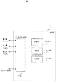
図1は本発明の一実施例における航空機通信方法を適用するシステムの構成を説明する図である。
本発明の一実施例における航空機通信方法を適用するシステムは、構成要素として移動局(航空機)、地上局、制御局からなる無線システムである。
移動局(航空機)1は飛行経路4上を運行するものとし、移動局1と地上局2−1、2−2、2−3との間で無線信号を送受信するためにアダプティブアレイアンテナを搭載しているものとする。
各地上局2−1、2−2、2−3は飛行経路4に沿って地上に配備しているものとし、移動局1と送受信するためにアダプティブアレイアンテナを搭載しており、指向性を持たせず全方位にビーム幅を広げた状態でかつ、上空の飛行経路4に向けて共通制御信号7(地上局の無線機IDを含む)を常時あるいは定期的に送信しているものとする。図1では、地上局2−2から送信される共通制御信号7のみ示したが、基地局2−1、2−3からも同様の共通制御信号7を送信する。
FIG. 1 is a diagram illustrating the configuration of a system to which an aircraft communication method according to an embodiment of the present invention is applied.
A system to which an aircraft communication method according to an embodiment of the present invention is applied is a wireless system including a mobile station (aircraft), a ground station, and a control station as components.
The mobile station (aircraft) 1 operates on the
Each ground station 2-1, 2-2, 2-3 is assumed to be deployed on the ground along the
制御局3は各地上局2−1、2−2、2−3と地上回線5で接続されており、移動局1から受信した多重化されたデータを地上回線5を介して伝送し、また他のネットワーク6にも伝送するものとする。
移動局1は、予め地上局の位置情報(緯度、経度、高度)を移動局1内に登録しており、地上局の位置情報(緯度、経度、高度)と航空機の位置情報(緯度、経度、高度、機体方向)を用いて、航空機に最も近い地上局を選択し、その地上局に向けたビームの放射方向を算定し、ビーム9−1を向ける。
図1を例にすると、移動局1は、地上局2−1が送信した共通制御信号7(地上局の無線機IDを含む)を受信すると、移動局1から地上局2−1に向けて、移動局1の無線機ID、位置情報及び接続要求信号8を送信する。
地上局2−1は移動局1から受信した情報に基づいて移動局1に向けた放射方向を算定する。地上局2−1は移動局1に対してビーム幅を狭めてビームフォーム9−2を向け追尾する。
移動局1が飛行経路4に沿って飛行して移動局1の通信相手である地上局2−1から地上局2−2、地上局2−3のカバーエリアに移動するときも、各地上局はアレイアンテナのビームフォーミングを実施して移動局1を追尾する。
The
The
Taking FIG. 1 as an example, when the
The ground station 2-1 calculates the radiation direction toward the
When the
図2は本発明の一実施例における移動局の構成を説明するである。
移動局1は、アレイアンテナ部1−A、無線装置部1−B、無線サービス部1−Cから構成される。
アレイアンテナ部1−Aはアレイアンテナ部1−A1、1−A2で構成し、移動局1と地上局2−1、2−2、2−3間の信号の送受信を行い、無線装置部1−Bの制御部1−B2によりアレイアンテナ部1−Aの位相を制御することでビームフォームを制御する。
図2では、本実施例の説明のために2組のアレイアンテナを実装する例を示しているが、移動局1と地上局間の無線通信システムに応じて1組のみあるいは3組以上のアレイアンテナを実装してもよい。
無線装置部1−Bは機内・機外と信号を送受信するための機内無線送受信部1−B6、機外無線送受信部1−B5、航空機の位置情報を取得するための航空機位置情報取得部1−B4、航空機と地上局2の位置情報とビームフォーム9−1の放射方向、ウェイト情報を格納するビームフォーム記憶部1−B1、無線装置部1−Bの制御を行う制御部1−B2、無線装置部1−Bの状態監視を行う監視部1−B3から構成される。
航空機位置情報取得部1−B4にはGPS信号受信部1−B7が実装されており、逐次、航空機の位置情報を取得し、取得した航空機の位置情報をビームフォーム記憶部1−B1の航空機位置情報テーブルH2に記録を行う。
無線サービス部1−Cは無線LAN、WiMAX、LTE等の高速無線サービスを提供し、アンテナ1−C1により航空機内の端末1−C2と無線信号の送受信を行う。
FIG. 2 explains the configuration of the mobile station in one embodiment of the present invention.
The
The array antenna unit 1-A includes array antenna units 1-A1 and 1-A2, and transmits and receives signals between the
FIG. 2 shows an example in which two sets of array antennas are mounted for the purpose of explaining this embodiment. However, only one set or three or more sets of arrays are used depending on the radio communication system between the
The wireless device unit 1-B includes an in-flight wireless transmission / reception unit 1-B6 for transmitting / receiving signals to / from the in-flight, an out-of-flight wireless transmission / reception unit 1-B5, and an aircraft position
The aircraft position information acquisition unit 1-B4 is equipped with a GPS signal reception unit 1-B7. The aircraft position information is sequentially acquired, and the acquired aircraft position information is stored in the aircraft position of the beamform storage unit 1-B1. Recording is performed in the information table H2.
The wireless service unit 1-C provides high-speed wireless services such as wireless LAN, WiMAX, and LTE, and transmits and receives wireless signals to and from the terminal 1-C2 in the aircraft using the antenna 1-C1.
図3は本発明の一実施例における地上局の構成を説明する図である。
地上局2はアレイアンテナ部2−A、無線装置部2−Bから構成される。
無線装置部2−Bの構成は、制御局3と通信するための制御局インターフェイス部2−B4、制御局インターフェイス部2−B4からの信号を無線信号に変換し、時分割多重方式などの方式により送受信するための無線送受信部2−B5、アレイアンテナ部のビームフォームの放射方向、ウェイト情報を格納するビームフォーム記憶部2−B1、制御部2−B2、監視部2−B3から構成される。
監視部2−B3により、移動局1からの通信品質(エラーレート、受信レベル、無線伝送路損失等)を監視し、制御局3に通知する。
アレイアンテナ部2−Aはアンテナエレメント部2−A1、ビームフォーム調整部2−A2からなり、無線装置部2−Bのビームフォームの算定によりビームフォーム調整部2−A2に電気的に重み付けをし、アンテナエレメント部2−A1から移動局1に向けてビームフォーミングを行う。
FIG. 3 is a diagram for explaining the configuration of the ground station in one embodiment of the present invention.
The
The configuration of the radio device unit 2-B is a control station interface unit 2-B4 for communicating with the
The monitoring unit 2-B3 monitors the communication quality (error rate, reception level, wireless transmission path loss, etc.) from the
The array antenna unit 2-A includes an antenna element unit 2-A1 and a beamform adjustment unit 2-A2, and electrically weights the beamform adjustment unit 2-A2 by calculating the beamform of the wireless device unit 2-B. Then, beam forming is performed from the antenna element unit 2-A1 toward the
図4は本発明の一実施例における制御局の構成を説明する図である。
制御局3は記憶部3−A1、制御部3−A2、監視部3−A3、インターフェイス部3−A4から構成される。
記憶部3−A1には、予め飛行経路4上の地上局2の無線機IDが登録されており、地上局2が送信する信号の回線品質(エラーレート、受信レベル、無線伝送路損失等)を記録している。
制御部3−A2は、各地上局2の位置情報の管理、移動局1のハンドオーバーの切替制御を行う。
監視部3−A3は、各地上局2の回線品質の情報を監視し、制御部3−A2により、回線品質(エラーレート、受信レベル)が良好な回線を選択する。
インターフェイス部3−A4は各地上局との通信を行う。また他のネットワーク6と接続し、各地上局からネットワーク6に信号を伝送するものとする。
FIG. 4 is a diagram illustrating the configuration of the control station in one embodiment of the present invention.
The
In the storage unit 3-A1, the radio ID of the
The control unit 3-A2 performs management of position information of each
The monitoring unit 3-A3 monitors information on the line quality of each
The interface unit 3-A4 communicates with each ground station. Further, it is assumed that a signal is transmitted from each ground station to the
図5は移動局の無線装置部のビームフォーム記憶部の構成を説明する図である。
ビームフォーム記憶部1−B1、2−B1はアレイアンテナ部1−A、2−Aと制御部1−B2、2−B2、監視部1−B3、2−B3と接続されており、移動局1のビームフォーム記憶部1−B1は航空機位置情報取得部1−B4と接続されている。ビームフォーム記憶部1−B1、2−B1は地上局位置情報テーブルH1、航空機位置情報テーブルH2、放射方向情報テーブルH3を備えている。ビームフォーム記憶部1−B1、2−B1には、予め地上局位置情報テーブルH1に全地上局の位置情報が格納されている。ビームフォーム9−1、9−2の放射方向を算定する際、制御部1−B2、2−B2にて読出しを行う。
航空機位置情報テーブルH2はビームフォーム記憶部1−B1、2−B1に各々備えている。移動局1のビームフォーム記憶部1−B1は航空機位置情報取得部1−B4から取得した位置情報、計測時刻を航空機位置情報テーブルH2に記憶する。
地上局2のビームフォーム記憶部2−B1は移動局1より航空機の位置情報、計測時刻を受けて記憶する。
制御部1−B2、2−B2はビームフォーム9−1、9−2の放射方向情報、ウェイト情報を算定し、算定した放射方向情報とウェイト情報を放射方向情報テーブルH3に記憶し、ビームフォーム9−1、9−2を制御するため放射方向情報、ウェイト情報の読出しを行う。
FIG. 5 is a diagram for explaining the configuration of the beamform storage unit of the radio apparatus unit of the mobile station.
Beamform storage units 1-B1 and 2-B1 are connected to array antenna units 1-A and 2-A, control units 1-B2 and 2-B2, and monitoring units 1-B3 and 2-B3. One beamform storage unit 1-B1 is connected to the aircraft position information acquisition unit 1-B4. The beamform storage units 1-B1 and 2-B1 include a ground station position information table H1, an aircraft position information table H2, and a radiation direction information table H3. In the beamform storage units 1-B1 and 2-B1, the position information of all the ground stations is stored in the ground station position information table H1 in advance. When calculating the radiation directions of the beam forms 9-1 and 9-2, reading is performed by the control units 1-B2 and 2-B2.
The aircraft position information table H2 is provided in each of the beamform storage units 1-B1 and 2-B1. The beamform storage unit 1-B1 of the
The beam form storage unit 2-B1 of the
The control units 1-B2 and 2-B2 calculate the radiation direction information and weight information of the beamforms 9-1 and 9-2, store the calculated radiation direction information and weight information in the radiation direction information table H3, and store the beamform. Reading of radiation direction information and weight information is performed to control 9-1 and 9-2.
図6は地上局位置情報テーブルの概略イメージ図である。
地上局位置情報テーブルには、予め全ての地上局の無線機IDと位置情報(緯度、経度、高度)を登録されているものとする。
FIG. 6 is a schematic image diagram of the ground station position information table.
It is assumed that the radio station IDs and position information (latitude, longitude, altitude) of all the ground stations are registered in advance in the ground station position information table.
図7は航空機位置情報テーブルのイメージ図である。
航空機位置情報テーブルには、移動局1のビームフォーム記憶部1−B1においては、航空機位置情報取得部1−B4から位置情報と計測時刻を取得し、移動局の無線機ID、計測時刻(時間h、分m、秒s)、航空機の位置情報(緯度、経度、高度)の項目を記憶し、随時更新する。
地上局2のビームフォーム記憶部1−B2においては、移動局1から接続要求信号(航空機の無線機ID、位置情報含む)を受信した際、移動局1と同様に随時更新する。
FIG. 7 is an image diagram of the aircraft position information table.
In the aircraft position information table, the beam form storage unit 1-B1 of the
In the beam form storage unit 1 -
図8は放射方向情報テーブルのイメージ図である。
放射方向情報テーブルには航空機位置情報取得部1−B4から取得した移動局1の無線機ID、計測時刻、その計測時刻に算定したビームフォーム9−1、9−2の放射方向(θ、φ、r)、ウェイト情報(ω)の項目を記憶させる。
FIG. 8 is an image diagram of the radiation direction information table.
In the radiation direction information table, the radio station ID of the
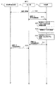
図9(a)、図9(b)は移動局と地上局間のビームフォーミング及び制御局との回線開通処理を説明するシーケンス図である。
地上局2は指向性を持たせず全方位にビーム幅を広げた状態でかつ、上空の飛行経路4に向けて共通制御信号7(地上局の無線機IDを含む)を常時あるいは定期的に送信(S1)しているものとする。
移動局1は、航空機位置情報取得部1−B4より移動局1の位置情報の取得(S2)を行い、位置情報をビームフォーム記憶部1−B1の航空機位置情報テーブルH2に記録(S3)を随時行う。移動局1は航空機位置情報テーブルH2から移動局1の位置情報の読出(S4)を行い、地上局位置情報テーブルH1から移動局1に最も近い地上局の位置情報の読出(S5)を行う。移動局1は無線装置部1−Bの制御部1−B2により、航空機の位置情報と地上局2の位置情報から、ビームフォーム9−1の放射方向と位相制御のためのウェイトの算定(S6)を行い、放射方向情報テーブルH3に記録(S7)を行う。移動局1は算定した電気的な重み付けであるウェイト情報によりアレイアンテナ部1(1−A1)に制御をかけ、ビームフォーム9−1を地上局2に向ける。移動局1は最も近い地上局2の共通制御信号7を受信する迄、S2〜S8までのビームフォーミングを繰り返し行う。(S9)
移動局1は、地上局2から送信(S10)される共通制御信号7(地上局の無線機IDを含む)を移動局1のアレイアンテナ部1(1−A1)にて受信(S11)した場合、移動局1は地上局2に向けて、接続要求信号(移動局1の無線機ID、位置情報を含む)の送信(S12)を行う。
FIG. 9A and FIG. 9B are sequence diagrams for explaining beam forming between the mobile station and the ground station and a line opening process between the control station.
The
The
The
地上局2は移動局1の接続要求信号を受け、無線チャネルの割当て(S13)を行い、制御局3に対し接続要求信号の伝送(S14)を行う。
制御局3は地上局2に対し接続応答信号の伝送(S15)を行い、地上局2は接続応答信号を受信したとき、ビームフォーミングを開始する。
地上局2は移動局1の接続要求信号に付随した位置情報(S12)を受け、無線装置部2−Bのビームフォーム記憶部2−B1にある航空機位置情報テーブルH2に記録(S16)を行い、地上局位置情報テーブルH1から地上局2の位置情報の読出(S17)を行う。地上局2は無線装置部2−Bの制御部2−B2により、移動局1から受けた位置情報と地上局2の位置情報から、ビームフォーム9−2の放射方向情報と位相制御のためのウェイト情報の算定(S18)を行う。地上局2は放射方向テーブルH3にビームフォーム9−2の放射方向情報とウェイト情報の記録(S19)を行う。地上局2は無線装置部2−Bの制御部2−B2により、算定した電気的な重み付けであるウェイト情報をビームフォーム調整部2−A2に送信し、ビームフォーム9−2を航空機1に向ける(S20)。地上局2は移動局1に対し、接続応答信号、無線チャネル割当通知及びビームフォーミング完了通知の送信(S21)を行う。
移動局1と地上局2の間で相互にビームフォーミングした状態で無線回線を確立し、移動局1と制御局3の間で回線1の開通(S22)を行う回線1開通(S22)の後、移動局1と地上局2の間でS2〜S8、S10〜S12、S16〜S21迄のビームフォーミングの過程を行う。ビームフォーミング完了通知の送信(S21)を受けて、再びS2から行うことで繰り返しビームフォーミングを行うことで、航空機1のビームフォーム9−1と地上局2のビームフォーム9−2を相互に向け合わせ追尾する。
The
The
The
After the
図10は移動局と制御局間の回線品質状況監視処理を説明するシーケンス図である。
回線1開通(S22)の後、地上局2にて回線1の通信品質情報(エラーレート、受信レベル、無線伝送路損失等)を制御局3に伝送(S23)を行う。
制御局3の監視部3−A3にて、地上局2からの通信品質情報(S23)を監視(S24)し、記憶部3−A1に記録(S25)を行う。制御部3−A2にて回線1の通信品質(エラーレート、受信レベル、無線伝送路損失等)が予め設定した閾値未満であるか算定(S26)を行う。制御局3は地上局2に対し、回線1の品質結果通知の伝送(S27)を行う。
地上局2は移動局1に対し、回線1の品質結果通知の送信(S28)を行う。
移動局1は回線1の品質結果通知(S28)を、ハンドオーバー先と接続を行うための判断基準にする。
FIG. 10 is a sequence diagram for explaining the line quality status monitoring process between the mobile station and the control station.
After the
The monitoring unit 3-A3 of the
The
The
図11(a)、図11(b)は移動局、地上局、制御局の間で回線開通している状況で、次の接続先の地上局と回線開通処理を説明するシーケンス図である。
先に航空機1、地上局2−1、制御局3の間で回線開通T1(図9(b)のS22と同じ)しているものとし、回線1とする。また航空機1のアレイアンテナ部1(1−A1)を使用して送受信しているものとする。
移動局1は航空機位置情報テーブルH2から移動局1の位置情報の読出(T2)を行い、地上局位置情報テーブルH1から移動局1に最も近い地上局の位置情報の読出(T3)を行う。移動局1は無線装置部1−Bの制御部1−B2により、航空機の位置情報と地上局2−2の位置情報から、ビームフォーム9−1の放射方向情報と位相制御のためのウェイト情報の算定(T4)を行い、放射方向情報テーブルH3に記録(T5)を行う。移動局1は算定した電気的な重み付けであるウェイト情報によりアレイアンテナ部2(1−A2)に制御をかけ、ビームフォーム9−1を地上局2−2に向ける(T6)。移動局1は地上局2−1の次に近い地上局2−2の共通制御信号7を受信する迄、T2〜T6までのビームフォーミングを繰り返し行う。(T7)
地上局2は指向性を持たせず全方位にビーム幅を広げた状態でかつ、上空の飛行経路4に向けて共通制御信号7(地上局の無線機IDを含む)を常時あるいは定期的に送信(T8)しているものとする。地上局2から送信(T9)される共通制御信号7(地上局の無線機IDを含む)を移動局1のアレイアンテナ部2(1−A2)にて受信(T10)し、かつ制御局3から地上局2−1に向けて回線1の品質結果通知(図10S26)を伝送(T11)し、地上局2−1から移動局1に対し、回線1の品質結果通知(図10S27)を送信(T12)し、アンテナアレイ部1(1−A1)にて回線1の品質結果通知を受信(T13)した場合、移動局1は地上局2−2に対して接続判定(T14)を行う。
地上局2−2が送信した共通制御信号7を受信(T10)し、かつ回線1の回線品質(エラーレート、受信レベル、無線伝送路損失等)の結果が予め設定した閾値以上の場合、地上局2−2に対し接続要求信号を送信しない。共通制御信号7を受信(T10)し、かつ回線1の回線品質(エラーレート、受信レベル、無線伝送路損失等)の結果が予め設定した閾値未満であるとき、移動局1は地上局2−2に向けて、接続要求信号(移動局1の無線機ID、位置情報を含む)の送信(T15)を行う。
地上局2−2は図9(b)のS13〜S20迄と同じ工程T16を行い、地上局2−2は移動局1に対し、接続応答信号、無線チャネル割当通知及びビームフォーミング完了通知の送信(T17)を行う。移動局1と地上局2−2の間で相互にビームフォーミングした状態で無線回線確立し、移動局1と制御局3の間で回線2の開通(T18)を行う。回線2開通(T18)の後、移動局1と地上局2−2の間でT2〜T6、T15〜T17迄のビームフォーミングの過程を行う。
ビームフォーミング完了通知の送信(T17)を受けて、再びT2から行うことで繰り返しビームフォーミングを行うことで、航空機1のビームフォーム9−1と地上局2−2のビームフォーム9−2を相互に向け合わせ追尾する。
FIG. 11A and FIG. 11B are sequence diagrams for explaining the next connection destination ground station and line opening process in a situation where the line is opened between the mobile station, the ground station, and the control station.
It is assumed that the
The
The
When the
The ground station 2-2 performs the same process T16 as S13 to S20 in FIG. 9B, and the ground station 2-2 transmits a connection response signal, a radio channel assignment notification, and a beamforming completion notification to the
Upon receiving the beamforming completion notification transmission (T17) and performing beamforming repeatedly from T2, the beamform 9-1 of the
図12は移動局と制御局の間で回線1、回線2が開通している状況で、制御局にて回線品質により回線選択を行う処理を説明するシーケンス図である。
移動局1と制御局3の間にて回線1が開通(T1)し、回線2が開通(T18)している二重接続の状況とする。
地上局2−1は回線1の通信品質情報(エラーレート、受信レベル、無線伝送路損失等)を制御局3に伝送(T19)し、地上局2−2は回線2の通信品質情報の伝送(T20)を行う。
制御局3の監視部3−A3にて、地上局2−1、地上局2−2からの通信品質情報T19、T20を監視(T21)し、記憶部3−A1に記録(T22)を行う。制御部3−A2により、T19、T20で受信した通信品質情報(エラーレート、受信レベル、無線伝送路損失等)を比較し、回線の品質判定(T23)を行う。
回線1、回線2はインターフェイス部3−A4まで接続状態のまま、品質判定(T23)の結果に基づき、制御部3−A2にて回線品質良好な回線番号を選択(T24)する。このとき未選択回線はインターフェイス部3−A4で接続状態である。
制御局3から地上局2−1、地上局2−2に対し、各々、選択結果通知(T26−1)、(T26−2)を行う。地上局2−1、地上局2−2は移動局1に対し、選択結果通知(T27−1),(T27−2)を送信する。
移動局1は選択結果通知T27−1,T27−2を回線切替えの判断情報として扱う。
地上局2−1、地上局2−2、制御局3はT19〜T27の過程を繰り返し行う(T28)。
FIG. 12 is a sequence diagram illustrating a process of selecting a line based on line quality at the control station in a situation where the
It is assumed that the
The ground station 2-1 transmits the communication quality information (error rate, reception level, radio transmission path loss, etc.) of the
The monitoring unit 3-A3 of the
The
The
The
The ground station 2-1, the ground station 2-2, and the
図13(a)、図13(b)は移動局−地上局間の回線切替え処理を説明するシーケンス図である。
移動局1と制御局3の間にて回線1が開通(T1)し、回線2が開通(T18)している二重接続の状況とする。
先に移動局1、地上局2−1、制御局3の間で回線開通(T1)しているものとし、回線1とする。また航空機1のアレイアンテナ部1(1−A1)を使用して送受信しているものとする。同様に回線1の開通の後に、航空機1、地上局2−2、制御局3の間で回線開通(T18)しているものとし回線2とする。また移動局1のアレイアンテナ部2(1−A2)を使用して送受信しているものとする。
FIGS. 13A and 13B are sequence diagrams for explaining the line switching process between the mobile station and the ground station.
It is assumed that the
It is assumed that the line is first opened (T1) among the
制御局3から地上局2−1、地上局2−2に対し、各々、回線の選択結果通知(T26−1)、(T26−2)を行い、地上局2−1、地上局2−2は回線切替えの判断情報として移動局1に対し、選択結果通知(T27−1),(T27−2)を送信する。
移動局1はビームフォーム記憶部1−B1の航空機位置情報テーブルH2から自機の位置情報の読出(U1)を行い、地上局位置情報テーブルH1から地上局2−1、地上局2−2の位置情報の読出(U2)を行う。移動局1は無線装置部1−Bの制御部1−B2により、航空機の位置情報と地上局2−1、地上局2−2の位置情報から、直線距離の算定(U3)を行い、航空機−各地上局間の直線距離判定(U4)を行う。航空機に対して地上局2−1の方が直線距離が近い場合、U1〜U4迄を繰り返す(U5)。航空機1に対して地上局2−1より、地上局2−2の方が直線距離が近い場合でかつ、回線2の選択結果通知(T27−2)が回線1の選択結果通知(T27−1)と比較して良好でかつ、予め設定した閾値以上であるとき、地上局2−1と地上局2−2でハンドオーバー開始(U5)とする。
この条件に合致しない場合、回線1、回線2の二重接続で運用とする。
The
The
If this condition is not met, the
ハンドオーバー開始(U5)として、移動局1は地上局2−1、地上局2−2に対し、各々回線切替要求信号の送信(U6−1),(U6−2)を行う。地上局2−1、地上局2−2は制御局3に対し、各々回線切替要求信号の伝送(U7−1),(U7−2)を行う。制御局3の監視部3−A3にて回線切替要求信号の(U7−1),(U7−2)の監視U9を行う。地上局2−1、地上局2−2は移動局1に対し、各々応答信号の送信(U8−1),(U8−2)を行う。制御局3は地上局2−1に対し、無線回線停止信号の伝送(U10)を行う。地上局2−1は移動局1に対し、無線回線停止信号の送信(U11)を行う。地上局2−1は無線チャネル解放を行い、移動局1の無線回線停止(U12)を行い、制御局3に対し応答通知(U13)を行う。地上局2−1はアレイアンテナ部2−Aのウェイト制御を解除し、ビームフォーム9−2を解放(U14)する。
地上局2−2は、共通制御信号7を送信し、図9(a)のS1を実施する(U15)。移動局1は地上局2−1向きの無線回線停止(U16)を行う。アレイアンテナ部1(1−A1)のウェイト制御を解放し、ビームフォーム9−1の解放(U17)を行う。地上局2−3に向けてアレイアンテナのビームフォーミングを行い、図9(a)のS2を実施する(U18)。地上局2−2は回線2の通信品質情報(エラーレート、受信レベル、無線伝送路損失等)を制御局3に伝送(U19)し、制御局3の監視部3−A3で通信品質情報を監視し、記憶部3−A1に記録(U20)を行う。
As a handover start (U5), the
The ground station 2-2 transmits the
1…移動局(航空機)、2…地上局、3…制御局、4…飛行経路、5…地上回線、6…ネットワーク、7…共通制御信号、8…航空機の位置情報、無線機ID、9…ビームフォーム
DESCRIPTION OF
Claims (5)
該複数の地上局と地上回線で接続され地上局を制御する制御局を少なくとも有する航空機通信システムにおける通信方法であって、
前記航空機は、
複数のアレイアンテナ部と、
該複数のアレイアンテナ部がそれぞれ別の方向にビームを送信するように制御する制御部と、位置情報取得部と、ビームフォームを行うための情報を記憶する記憶部を有する無線装置部と、
航空機内の端末と無線信号を送受信する無線サービス部とを有し、
前記記憶部に、前記複数の地上局の位置情報および、前記位置情報取得部が取得した航空機の位置情報を記憶しており、
該複数の地上局の位置情報および航空機の位置情報に基づいて、少なくとも一つの地上局を選択し、該地上局に向けたビームを形成して送信し、
前記地上局は、
アレイアンテナ部と
該アレイアンテナ部が送信するビームを制御する制御部と、ビームフォームを行うための情報を記憶する記憶部を有する無線装置部と、を有し、
前記航空機および前記地上局の双方がビームフォーミングを行うことにより通信を継続することを特徴とする航空機通信方法。 An aircraft and a plurality of ground stations located on the flight path of the aircraft;
A communication method in an aircraft communication system having at least a control station connected to the plurality of ground stations via a ground line and controlling the ground station,
The aircraft
A plurality of array antenna sections;
A control unit that controls the plurality of array antenna units to transmit beams in different directions, a position information acquisition unit, and a wireless device unit that includes a storage unit that stores information for performing beamform;
A wireless service unit that transmits and receives wireless signals to and from terminals in the aircraft;
The storage unit stores position information of the plurality of ground stations and position information of the aircraft acquired by the position information acquisition unit,
Based on the position information of the plurality of ground stations and the position information of the aircraft, select at least one ground station, and form and transmit a beam toward the ground station;
The ground station is
An array antenna unit, a control unit that controls a beam transmitted by the array antenna unit, and a wireless device unit that includes a storage unit that stores information for performing beamform,
An aircraft communication method characterized in that both the aircraft and the ground station continue communication by performing beamforming.
航空機の飛行経路上に配置された複数の地上局と、
該複数の地上局と地上回線で接続され地上局を制御する制御局を少なくとも有する航空機通信システムであって、
前記航空機は、
複数のアレイアンテナ部と、
該複数のアレイアンテナ部がそれぞれ別の方向にビームを送信するように制御する制御部と、位置情報取得部と、ビームフォームを行うための情報を記憶する記憶部を有する無線装置部と、
航空機内の端末と無線信号を送受信する無線サービス部とを有し、
前記記憶部に、前記複数の地上局の位置情報および、前記位置情報取得部が取得した航空機の位置情報を記憶しており、
該複数の地上局の位置情報および航空機の位置情報に基づいて、少なくとも一つの地上局を選択し、該地上局に向けたビームを形成して送信し、
前記地上局は、
アレイアンテナ部と
該アレイアンテナ部が送信するビームを制御する制御部と、ビームフォームを行うための情報を記憶する記憶部を有する無線装置部と、を有し、
前記航空機および前記地上局の双方がビームフォーミングにより通信を行うことを特徴とする航空機通信システム。 An aircraft,
A plurality of ground stations located on the flight path of the aircraft;
An aircraft communication system having at least a control station connected to the plurality of ground stations via a ground line and controlling the ground station,
The aircraft
A plurality of array antenna sections;
A control unit that controls the plurality of array antenna units to transmit beams in different directions, a position information acquisition unit, and a wireless device unit that includes a storage unit that stores information for performing beamform;
A wireless service unit that transmits and receives wireless signals to and from terminals in the aircraft;
The storage unit stores position information of the plurality of ground stations and position information of the aircraft acquired by the position information acquisition unit,
Based on the position information of the plurality of ground stations and the position information of the aircraft, select at least one ground station, and form and transmit a beam toward the ground station;
The ground station is
An array antenna unit, a control unit that controls a beam transmitted by the array antenna unit, and a wireless device unit that includes a storage unit that stores information for performing beamform,
An aircraft communication system, wherein both the aircraft and the ground station perform communication by beam forming.
Priority Applications (1)
| Application Number | Priority Date | Filing Date | Title |
|---|---|---|---|
| JP2013085354A JP2014207626A (en) | 2013-04-16 | 2013-04-16 | Aircraft communication method and aircraft communication system |
Applications Claiming Priority (1)
| Application Number | Priority Date | Filing Date | Title |
|---|---|---|---|
| JP2013085354A JP2014207626A (en) | 2013-04-16 | 2013-04-16 | Aircraft communication method and aircraft communication system |
Publications (1)
| Publication Number | Publication Date |
|---|---|
| JP2014207626A true JP2014207626A (en) | 2014-10-30 |
Family
ID=52120846
Family Applications (1)
| Application Number | Title | Priority Date | Filing Date |
|---|---|---|---|
| JP2013085354A Pending JP2014207626A (en) | 2013-04-16 | 2013-04-16 | Aircraft communication method and aircraft communication system |
Country Status (1)
| Country | Link |
|---|---|
| JP (1) | JP2014207626A (en) |
Cited By (24)
| Publication number | Priority date | Publication date | Assignee | Title |
|---|---|---|---|---|
| JP2016192693A (en) * | 2015-03-31 | 2016-11-10 | セコム株式会社 | Mobile communication device |
| JP2018078524A (en) * | 2016-11-11 | 2018-05-17 | 株式会社東芝 | Radio transmission device and radio transmission method |
| JP2018127201A (en) * | 2016-12-09 | 2018-08-16 | ザ・ボーイング・カンパニーThe Boeing Company | Phased array antennas for high altitude platforms |
| WO2018211627A1 (en) * | 2017-05-17 | 2018-11-22 | 富士通株式会社 | Wireless base station, wireless terminal, wireless communication system, and wireless communication method |
| WO2019049390A1 (en) * | 2017-09-08 | 2019-03-14 | パナソニックIpマネジメント株式会社 | Communication device, communication system, and communication method |
| JP2019161787A (en) * | 2018-03-09 | 2019-09-19 | 株式会社東芝 | On-vehicle device, ground device and wireless communication method |
| JP2019527505A (en) * | 2016-07-13 | 2019-09-26 | スマートスカイ ネットワークス エルエルシーSmartsky Networks Llc | Air-to-ground communication system having separate control and traffic channels |
| WO2020027990A1 (en) * | 2018-07-30 | 2020-02-06 | Pivotal Commware, Inc. | Distributed antenna networks for wireless communication by wireless devices |
| US10594033B1 (en) | 2018-09-19 | 2020-03-17 | Pivotal Commware, Inc. | Surface scattering antenna systems with reflector or lens |
| US10734736B1 (en) | 2020-01-03 | 2020-08-04 | Pivotal Commware, Inc. | Dual polarization patch antenna system |
| US10863458B2 (en) | 2018-03-19 | 2020-12-08 | Pivotal Commware, Inc. | Communication of wireless signals through physical barriers |
| US10971813B2 (en) | 2019-02-20 | 2021-04-06 | Pivotal Commware, Inc. | Switchable patch antenna |
| US11026055B1 (en) | 2020-08-03 | 2021-06-01 | Pivotal Commware, Inc. | Wireless communication network management for user devices based on real time mapping |
| US11069975B1 (en) | 2020-04-13 | 2021-07-20 | Pivotal Commware, Inc. | Aimable beam antenna system |
| US11088433B2 (en) | 2019-02-05 | 2021-08-10 | Pivotal Commware, Inc. | Thermal compensation for a holographic beam forming antenna |
| US11190266B1 (en) | 2020-05-27 | 2021-11-30 | Pivotal Commware, Inc. | RF signal repeater device management for 5G wireless networks |
| US11297606B2 (en) | 2020-09-08 | 2022-04-05 | Pivotal Commware, Inc. | Installation and activation of RF communication devices for wireless networks |
| US11451287B1 (en) | 2021-03-16 | 2022-09-20 | Pivotal Commware, Inc. | Multipath filtering for wireless RF signals |
| JP2022544639A (en) * | 2019-08-16 | 2022-10-20 | エイブイエックス・アンテナ・インコーポレーテッド | A method for estimating a transmitted signal channel quality indicator based on a received signal channel quality indicator |
| US11497050B2 (en) | 2021-01-26 | 2022-11-08 | Pivotal Commware, Inc. | Smart repeater systems |
| US11843955B2 (en) | 2021-01-15 | 2023-12-12 | Pivotal Commware, Inc. | Installation of repeaters for a millimeter wave communications network |
| US11929822B2 (en) | 2021-07-07 | 2024-03-12 | Pivotal Commware, Inc. | Multipath repeater systems |
| US11937199B2 (en) | 2022-04-18 | 2024-03-19 | Pivotal Commware, Inc. | Time-division-duplex repeaters with global navigation satellite system timing recovery |
| US11968593B2 (en) | 2021-05-28 | 2024-04-23 | Pivotal Commware, Inc. | Wireless communication network management for user devices based on real time mapping |
-
2013
- 2013-04-16 JP JP2013085354A patent/JP2014207626A/en active Pending
Cited By (40)
| Publication number | Priority date | Publication date | Assignee | Title |
|---|---|---|---|---|
| JP2016192693A (en) * | 2015-03-31 | 2016-11-10 | セコム株式会社 | Mobile communication device |
| JP2019527505A (en) * | 2016-07-13 | 2019-09-26 | スマートスカイ ネットワークス エルエルシーSmartsky Networks Llc | Air-to-ground communication system having separate control and traffic channels |
| JP7068266B2 (en) | 2016-07-13 | 2022-05-16 | スマートスカイ ネットワークス エルエルシー | Air-to-ground communication system with separate control and traffic channels |
| JP2018078524A (en) * | 2016-11-11 | 2018-05-17 | 株式会社東芝 | Radio transmission device and radio transmission method |
| JP2018127201A (en) * | 2016-12-09 | 2018-08-16 | ザ・ボーイング・カンパニーThe Boeing Company | Phased array antennas for high altitude platforms |
| JP7169743B2 (en) | 2016-12-09 | 2022-11-11 | ザ・ボーイング・カンパニー | Phased array antenna for high altitude platforms |
| WO2018211627A1 (en) * | 2017-05-17 | 2018-11-22 | 富士通株式会社 | Wireless base station, wireless terminal, wireless communication system, and wireless communication method |
| US11297623B2 (en) | 2017-09-08 | 2022-04-05 | Panasonic Intellectual Property Management Co., Ltd. | System and method for air-to-ground communication involving an aircraft |
| WO2019049390A1 (en) * | 2017-09-08 | 2019-03-14 | パナソニックIpマネジメント株式会社 | Communication device, communication system, and communication method |
| JP2019161787A (en) * | 2018-03-09 | 2019-09-19 | 株式会社東芝 | On-vehicle device, ground device and wireless communication method |
| US11706722B2 (en) | 2018-03-19 | 2023-07-18 | Pivotal Commware, Inc. | Communication of wireless signals through physical barriers |
| US10863458B2 (en) | 2018-03-19 | 2020-12-08 | Pivotal Commware, Inc. | Communication of wireless signals through physical barriers |
| JP7451491B2 (en) | 2018-07-30 | 2024-03-18 | ピヴォタル コムウェア インコーポレイテッド | Distributed antenna network for wireless communication by wireless devices |
| US10862545B2 (en) | 2018-07-30 | 2020-12-08 | Pivotal Commware, Inc. | Distributed antenna networks for wireless communication by wireless devices |
| US11431382B2 (en) | 2018-07-30 | 2022-08-30 | Pivotal Commware, Inc. | Distributed antenna networks for wireless communication by wireless devices |
| WO2020027990A1 (en) * | 2018-07-30 | 2020-02-06 | Pivotal Commware, Inc. | Distributed antenna networks for wireless communication by wireless devices |
| US11374624B2 (en) | 2018-07-30 | 2022-06-28 | Pivotal Commware, Inc. | Distributed antenna networks for wireless communication by wireless devices |
| US10594033B1 (en) | 2018-09-19 | 2020-03-17 | Pivotal Commware, Inc. | Surface scattering antenna systems with reflector or lens |
| US11088433B2 (en) | 2019-02-05 | 2021-08-10 | Pivotal Commware, Inc. | Thermal compensation for a holographic beam forming antenna |
| US11848478B2 (en) | 2019-02-05 | 2023-12-19 | Pivotal Commware, Inc. | Thermal compensation for a holographic beam forming antenna |
| US11757180B2 (en) | 2019-02-20 | 2023-09-12 | Pivotal Commware, Inc. | Switchable patch antenna |
| US10971813B2 (en) | 2019-02-20 | 2021-04-06 | Pivotal Commware, Inc. | Switchable patch antenna |
| JP7459144B2 (en) | 2019-08-16 | 2024-04-01 | エイブイエックス・アンテナ・インコーポレーテッド | Method for estimating transmitted signal channel quality index based on received signal channel quality index |
| JP2022544639A (en) * | 2019-08-16 | 2022-10-20 | エイブイエックス・アンテナ・インコーポレーテッド | A method for estimating a transmitted signal channel quality indicator based on a received signal channel quality indicator |
| US11563279B2 (en) | 2020-01-03 | 2023-01-24 | Pivotal Commware, Inc. | Dual polarization patch antenna system |
| US10998642B1 (en) | 2020-01-03 | 2021-05-04 | Pivotal Commware, Inc. | Dual polarization patch antenna system |
| US10734736B1 (en) | 2020-01-03 | 2020-08-04 | Pivotal Commware, Inc. | Dual polarization patch antenna system |
| US11670849B2 (en) | 2020-04-13 | 2023-06-06 | Pivotal Commware, Inc. | Aimable beam antenna system |
| US11069975B1 (en) | 2020-04-13 | 2021-07-20 | Pivotal Commware, Inc. | Aimable beam antenna system |
| US11424815B2 (en) | 2020-05-27 | 2022-08-23 | Pivotal Commware, Inc. | RF signal repeater device management for 5G wireless networks |
| US11190266B1 (en) | 2020-05-27 | 2021-11-30 | Pivotal Commware, Inc. | RF signal repeater device management for 5G wireless networks |
| US11026055B1 (en) | 2020-08-03 | 2021-06-01 | Pivotal Commware, Inc. | Wireless communication network management for user devices based on real time mapping |
| US11297606B2 (en) | 2020-09-08 | 2022-04-05 | Pivotal Commware, Inc. | Installation and activation of RF communication devices for wireless networks |
| US11844050B2 (en) | 2020-09-08 | 2023-12-12 | Pivotal Commware, Inc. | Installation and activation of RF communication devices for wireless networks |
| US11843955B2 (en) | 2021-01-15 | 2023-12-12 | Pivotal Commware, Inc. | Installation of repeaters for a millimeter wave communications network |
| US11497050B2 (en) | 2021-01-26 | 2022-11-08 | Pivotal Commware, Inc. | Smart repeater systems |
| US11451287B1 (en) | 2021-03-16 | 2022-09-20 | Pivotal Commware, Inc. | Multipath filtering for wireless RF signals |
| US11968593B2 (en) | 2021-05-28 | 2024-04-23 | Pivotal Commware, Inc. | Wireless communication network management for user devices based on real time mapping |
| US11929822B2 (en) | 2021-07-07 | 2024-03-12 | Pivotal Commware, Inc. | Multipath repeater systems |
| US11937199B2 (en) | 2022-04-18 | 2024-03-19 | Pivotal Commware, Inc. | Time-division-duplex repeaters with global navigation satellite system timing recovery |
Similar Documents
| Publication | Publication Date | Title |
|---|---|---|
| JP2014207626A (en) | Aircraft communication method and aircraft communication system | |
| US10833759B2 (en) | Wireless communication location reporting and paging | |
| Koivisto et al. | High-efficiency device positioning and location-aware communications in dense 5G networks | |
| KR101263223B1 (en) | System architecture for providing communications in a wireless communication network | |
| EP3373471B1 (en) | Method and apparatus for focused data communications | |
| JP6748195B2 (en) | Low cost satellite user terminal antenna | |
| EP3868034B1 (en) | Position likelihood based beamformer optimization | |
| US11784730B2 (en) | Apparatus, system and method for improving position estimation and/or communication performance in a wireless communication network | |
| WO2020139369A1 (en) | Unmanned aerial vehicle antenna configurations | |
| US20140010155A1 (en) | Maritime broadband mobile communication apparatus and communication method using the same | |
| CN109890037A (en) | The method of adjustment and system of direction of arrival | |
| CN110383706A (en) | Electronic equipment and method for wireless communication | |
| EP3742626A1 (en) | Dynamic azimuth adjustment for cellular repeater antenna systems | |
| US11522600B1 (en) | Airborne RF-head system | |
| JP6924206B2 (en) | Base station equipment, communication systems, beam control methods and programs | |
| WO2022247685A1 (en) | Information transmission method, reflecting device, base station, system, electronic device, and medium | |
| EP3503421A1 (en) | Base station system for transmitting data towards a user entity | |
| US20200313728A1 (en) | Base station system for transmitting a data stream towards a user entity | |
| CN116566459A (en) | Satellite control method, service switching method, device and storage medium |