JP2014206650A - Light quantity adjusting device, optical instrument, and imaging apparatus - Google Patents
Light quantity adjusting device, optical instrument, and imaging apparatus Download PDFInfo
- Publication number
- JP2014206650A JP2014206650A JP2013084305A JP2013084305A JP2014206650A JP 2014206650 A JP2014206650 A JP 2014206650A JP 2013084305 A JP2013084305 A JP 2013084305A JP 2013084305 A JP2013084305 A JP 2013084305A JP 2014206650 A JP2014206650 A JP 2014206650A
- Authority
- JP
- Japan
- Prior art keywords
- aperture
- base member
- blades
- blade
- diaphragm
- Prior art date
- Legal status (The legal status is an assumption and is not a legal conclusion. Google has not performed a legal analysis and makes no representation as to the accuracy of the status listed.)
- Pending
Links
Images


Abstract
Description
本発明は、撮像装置や交換レンズ等の光学機器に搭載される光量調節装置に関する。 The present invention relates to a light amount adjusting device mounted on an optical apparatus such as an imaging device or an interchangeable lens.
撮像装置などに用いられる光量調節装置(絞り装置)においては、光を通過させる絞り開口を複数の羽根によって形成している。特許文献1には、ベース部材に形成された固定開口の周囲で、回動可能な駆動リングを用いて多数枚の絞り羽根を移動(回動)させ、多角形の絞り開口を形成する虹彩絞り装置が開示されている。
2. Description of the Related Art In a light amount adjusting device (aperture device) used for an imaging device or the like, an aperture opening through which light passes is formed by a plurality of blades. In
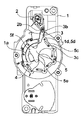
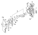
しかしながら、従来の虹彩絞り装置では、以下のような問題がある。図10には、従来の虹彩絞り装置を含む撮像装置の構成を示している。101は絞り装置のベース部材であり、103はベース部材101の固定開口の周囲で回動可能な駆動リングである。106は駆動リング103を回動させるアクチュエータであり、105は駆動リング103によって、ベース部材101に設けられた軸部(図示せず)を中心として回動される複数の絞り羽根である。さらに、114は絞り装置に隣接して配置されたレンズであり、113はレンズ114および絞り装置を含む撮影光学系により形成された被写体像を光電変換する撮像素子である。
However, the conventional iris diaphragm device has the following problems. FIG. 10 shows a configuration of an imaging apparatus including a conventional iris diaphragm apparatus.
図10には、複数の絞り羽根105を絞り込んで小絞り開口を形成した状態を示している。絞り開口を絞り込んでいくと、複数の絞り羽根105は、その先端同士が互いに重なり合うことでレンズ114側に反っていく。このため、この反った絞り羽根105とレンズ114との干渉を避けるために、絞り装置に対するレンズ14の退避スペースhを予め確保しておく必要がある。この結果、撮像装置が大型化する。
FIG. 10 shows a state where a plurality of
本発明は上述した課題に鑑みてなされたものであり、その目的は、羽根の安定駆動を実現できて小型化に有利な光量調節装置およびこれを備えた光学機器を提供することである。 The present invention has been made in view of the above-described problems, and an object of the present invention is to provide a light amount adjusting device that can realize stable driving of blades and is advantageous for downsizing, and an optical apparatus including the same.
本発明に係わる光量調節装置は、光が通過する開口部を形成する光通過開口形成部材と、前記開口部内に向けて回動する複数の光量調節羽根とを備え、前記複数の光量調節羽根は、羽根の回動方向先端部が前記開口部内に位置するときに回動方向後端部が前記開口部の縁部に重なる非横断型回動羽根を含むことを特徴とする。なお、ここでいう前記光通過開口形成部材は、光が通過する固定開口が形成された固定開口形成部材、または前記複数の光量調節羽根を回動させる環状の駆動部材を含むものである。 The light quantity adjusting device according to the present invention includes a light passage opening forming member that forms an opening through which light passes, and a plurality of light quantity adjusting blades that rotate toward the inside of the opening. The blade includes a non-transverse rotating blade whose rear end portion in the rotation direction overlaps with an edge of the opening portion when the leading end portion in the rotation direction of the blade is located in the opening portion. The light passage opening forming member here includes a fixed opening forming member in which a fixed opening through which light passes is formed, or an annular driving member for rotating the plurality of light quantity adjusting blades.
また、本発明に係わる光量調節装置は、光が通過する固定開口が形成されたベース部材と、前記光の進行方向である光軸方向において部分的に重なり合って前記固定開口を絞る絞り開口を形成し、前記ベース部材に対して回動して前記絞り開口を変化させる複数の絞り羽根とを有し、前記複数の絞り羽根は、少なくとも前記絞り開口が最小である最小絞り状態において、各絞り羽根のうち前記ベース部材に対する回動中心側とは反対側の端部である先端部が、前記光軸方向に前記ベース部材に重ならず、前記回動中心側及び前記先端部とは別の支持部で前記ベース部材と重なる複数の第1の絞り羽根と、少なくとも前記最小絞り状態において、各絞り羽根のうち前記ベース部材に対する回動中心側とは反対側の端部である先端部が、前記光軸方向に前記ベース部材に重なる複数の第2の絞り羽根とを含み、前記第2の絞り羽根が、前記第1の絞り羽根に対して、前記光軸方向のうち前記ベース部材に近い側およびその反対側のうち少なくとも一方において重なっていることを特徴とする。 Further, the light amount adjusting device according to the present invention forms a diaphragm aperture that restricts the fixed aperture by partially overlapping with a base member in which a fixed aperture through which light passes is formed in the optical axis direction that is the light traveling direction. And a plurality of aperture blades that rotate with respect to the base member to change the aperture opening, and each of the aperture blades is at least in the minimum aperture state where the aperture aperture is minimum. The tip portion that is the end opposite to the rotation center side of the base member does not overlap the base member in the optical axis direction, and is supported separately from the rotation center side and the tip portion. A plurality of first diaphragm blades that overlap the base member at a portion, and at least in the minimum diaphragm state, a distal end portion that is an end portion of each diaphragm blade on the side opposite to the rotation center side with respect to the base member, optical axis A plurality of second diaphragm blades that overlap the base member in the direction, the second diaphragm blades with respect to the first diaphragm blades in the direction of the optical axis close to the base member and its It is characterized by overlapping on at least one of the opposite sides.
本発明によれば、羽根の安定駆動を実現できて小型化に有利な光量調節装置およびこれを備えた光学機器を提供することが可能となる。 ADVANTAGE OF THE INVENTION According to this invention, it becomes possible to provide the light quantity adjustment apparatus which can implement | achieve the stable drive of a blade | wing and is advantageous for size reduction, and an optical apparatus provided with the same.
以下、本発明の実施形態について添付図面を参照して詳細に説明する。 Hereinafter, embodiments of the present invention will be described in detail with reference to the accompanying drawings.
(第1の実施形態)
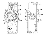
図1は、本発明の光量調節装置の第1の実施形態である虹彩絞り装置を分解して示した図である。また、図2および図3には、それぞれ本実施形態の虹彩絞り装置において用いられる第2の絞り羽根と第1の絞り羽根を示している。さらに、図4には、第1および第2の絞り羽根によって最小絞り開口Aが形成された状態を示している。
(First embodiment)
FIG. 1 is an exploded view of an iris diaphragm device that is a first embodiment of a light amount adjusting device of the present invention. 2 and 3 show a second diaphragm blade and a first diaphragm blade respectively used in the iris diaphragm device of the present embodiment. Further, FIG. 4 shows a state in which the minimum aperture A is formed by the first and second aperture blades.
本実施形態の絞り装置は、光が通過する開口部を有する光通過開口形成部材によって光通過経路を作り、当該光通過経路(開口部)内に移動する複数の羽根によって光量を調節するための装置となる。具体的には、絞り装置は、光が通過する固定開口1aが形成されたベース部材1(固定開口形成部材)を有する。すなわち、ベース部材1は、光通過開口形成部材の1つとなる。このベース部材1は、後に詳しく説明する複数の絞り羽根(複数の第1の絞り羽根5および複数の第2の絞り羽根4)の回動中心となる複数の軸部1dと、後述する駆動リング3の回転を案内するガイド1eとを有する。固定開口1aおよび複数の絞り羽根により形成される絞り開口を通過する光の進行方向(光の通過方向)を、以下、光軸方向という。
The diaphragm device according to the present embodiment creates a light passage path by a light passage opening forming member having an opening through which light passes, and adjusts the amount of light by a plurality of blades moving in the light passage path (opening). It becomes a device. Specifically, the diaphragm device includes a base member 1 (fixed opening forming member) in which a fixed
羽根駆動部6はステッピングモータ等のアクチュエータにより構成され、ベース部材1に取り付けられている。羽根駆動部6の出力軸には、羽根駆動アーム2が取り付けられている。羽根駆動アーム2には、リング駆動ピン2bが設けられている。
The
環状の駆動部材となる駆動リング3には、リング駆動ピン2bと係合する長孔部3bと、複数(本実施形態では8枚)の絞り羽根4,5を回動させる複数の羽根駆動ピン3cとが設けられている。複数の羽根駆動ピン3cのそれぞれは4枚の第2の絞り羽根4のそれぞれの基端部に形成されたカム孔部4cに係合しており、残りの羽根駆動ピン3cは残りの4枚の第1の絞り羽根5のそれぞれの基端部に形成されたカム孔部5cに係合している。第1および第2の絞り羽根5,4の基端部には、さらにベース部材1の軸部1dが挿入される孔部5d,4dが形成されている。なお、この駆動リング3は、光通過経路を取り囲む環状の部材によって構成されている。すなわち、駆動リング3は、上述した光が通過する開口部を有する光通過開口形成部材の一つとなる。
The
第1および第2の絞り羽根5,4は、光軸方向において部分的に重なり合って光通過開口を絞って絞り開口を形成する。ここで、各絞り羽根において、回動中心側である基端部とは反対側の部分を先端部5e,4eと呼び、基端部と先端部との間の部分を中間部と呼ぶ。また、第1の絞り羽根5において、回動中心である基端部および先端部5eとは別で、少なくとも最小絞り状態においてベース部材に重なる部分を支持部5fと呼ぶ。すなわち、第1の絞り羽根5は、羽根の回動方向における先端部5e(回動方向先端部)が光通過開口内に位置するときに回動方向後端部5f(後端側)が光通過開口形成部材(開口部の縁部)に重なる非横断型回動羽根となる。このような非横断型回動羽根は、基端側で回動支持された状態において、その回動動作範囲内において基端部以外の少なくとも一部(上記では回動方向後端部)が光通過開口を形成する部材(光通過開口形成部材)に重なる形状を持つ羽根となる。このような非横断型回動羽根を含めることにより、この非横断型回動羽根に対して他の羽根が重なると、非横断型回動羽根によって隣接する羽根が支持され、全体として安定駆動が可能となる。一方、第2の絞り羽根4は、光通過開口を実質的に横断し、光通過開口形成部材(開口部の縁部)に実質的に重なる横断型回転駆動羽根となる。
The first and
ここで、例えば、本実施形態では、複数の非横断型回動羽根と複数の横断型回動羽根とを併用して、光通過開口の形状を形成し、光量調節を行う構成となる。このとき、複数の非横断型回動羽根である第1の絞り羽根5からなる群を第1羽根群とし、複数の横断型回動羽根である第2の絞り羽根4からなる群を第2羽根群とした場合、例えば、本実施形態では、第1羽根群が第2羽根群に重なり、光量調節構造を実現している。これにより、第1羽根群が第2羽根群によって実質的に支持され、羽根の安定駆動を実現することが可能となる。特に、本実施形態では、第1の絞り羽根(非横断型回動羽根)5の外形は第2の絞り羽根(横断型回動羽根)4よりも小さいことから、第2の絞り羽根4によって第1の絞り羽根5が実質的に支えられることになる。また、第1羽根群を構成する非横断型回動羽根は、回動方向の先端部5eが開口部内に位置するときに回動方向の後端部5fが開口部の縁部に重なっていることから、羽根自体の反りを防ぐことができ、第1羽根群においても安定駆動を実現することが可能となる。そのため、光量調節羽根の全数を非横断型回動羽根で構成してもよく、これにより、光量調節装置の更なる小型化を実現できる。ただし、羽根の安定駆動を考慮して、1枚又は複数枚の横断型回動羽根を含めるようにしてもよい。横断型回動羽根は、非横断型回動羽根と比べて外形が大きいことから、相互に重なり合う羽根群の安定駆動という点でメリットがある。また、横断型回動羽根以外の羽根を含めて光量調節羽根を構成する場合においては、回動しない非回動羽根(直線移動する羽根)を用いて安定駆動を確保するようにしてもよく、更に上述した非横断型回動羽根、横断型回動羽根を含めて光量調節羽根を構成するようにしてもよい。なお、非回動羽根を含めて光量調節羽根を構成する場合には、横断型回動羽根と非横断型回動羽根との間に非回動羽根を配置することで、横断型回動羽根と非横断型回動羽根との仕切り部材としての役割も果たす。これにより、更なる安定駆動を実現することが可能となる。なお、非回動羽根としては、光通過開口を有する1枚の羽根でもよいし、羽根移動方向において対向配置される一対の羽根でもよい。後者の場合には、一対の羽根における対向する端部の形状によって光通過開口を形成するようにすればよい。
Here, for example, in the present embodiment, a plurality of non-transverse rotating blades and a plurality of transverse rotating blades are used in combination to form a light passage opening and adjust the light amount. At this time, a group of
ところで、本実施形態においては、羽根駆動部6によって羽根駆動アーム2が回動されて駆動リング3が回転すると、羽根駆動ピン3cがカム孔部5c,4c内を移動しながら第1および第2の絞り羽根5,4を軸部1dを中心として回動させる。これにより、絞り開口が、全ての絞り羽根4,5が固定開口1aの領域外に退避することで形成される開放絞り開口と、全ての絞り羽根4,5の重なり量が最も多くなって形成される最小絞り開口Aとの間で変化し、この絞り開口を通過する光の量が調節される。なお、以下の説明において、開放絞り開口が形成された状態を開放状態といい、最小絞り開口Aが形成された状態を最小絞り状態という。
By the way, in the present embodiment, when the
カバー部材としての仕切り板7は、ベース部材1の固定開口1aと同じ径の固定開口7aを有しており、ベース部材1との間に駆動リング3と絞り羽根4,5を挟んで、後述するケース11とともにベース部材1にビスにより固定される。すなわち、仕切り板7は、固定開口7aが光通過経路となることから、光が通過する開口部を有する光通過開口形成部材の一つとなる。
The partition plate 7 as a cover member has a fixed
また、仕切り板7に対して絞り羽根4,5とは反対側に、NDフィルタ8を保持したフィルタ保持板9が配置される。フィルタ保持板9は、不図示のフィルタ駆動部によって回動されるNDアーム10によって平行移動するように駆動され、絞り開口の領域に対して挿抜される。絞り開口の領域に挿入されたNDフィルタ8は、絞り開口を通過する光を減衰させる。これにより、絞り開口を、いわゆる小絞り回折が発生するほど絞り込まなくても、絞り開口を通過する光の量を調節することができる。
Further, a
ケース11は、仕切り板7との間にフィルタ保持板9を挟んで、仕切り板7とともにベース部材1にビスにより固定される。
The
本実施形態の絞り装置において、第2の絞り羽根4は、開放絞り開口(固定開口1a)より小さい絞り開口が形成される全ての絞り状態において、図2に示すように中間部がベース部材1の固定開口1aを横断するように延び、先端部4eが光軸方向にベース部材1に重なる。仕切り板7は、第2の絞り羽根4の先端部4eを、ベース部材1との間で挟み込むようにして回動可能に支持する。一方、第1の絞り羽根5は、図3に示すように、少なくとも最小絞り状態では、固定開口1aを横断せず、その先端部5eは光軸方向にベース部材1に重ならない。第1の絞り羽根5は、図3に示すように、少なくとも最小絞り状態では、支持部5fがベース部材に重なる。
In the diaphragm device of the present embodiment, the
そして、本実施形態では、図1および図4に示すように、第2の絞り羽根4を、複数の第1の絞り羽根5よりも光軸方向のベース部材1に近い側に配置している。このため、少なくとも複数の第1の絞り羽根5の大部分が重なり合って最小絞り開口を形成する最小絞り状態では、第2の絞り羽根4の中間部によって第1の絞り羽根5の光軸方向(ベース部材1側)への反りを制限するようにこれら第1の絞り羽根5を押さえる。この反りの制限効果は、最小絞り開口だけでなく、その近傍サイズの絞り開口が形成される状態においても得ることができる。したがって、図5に示すように、第1の絞り羽根5のベース部材1側への反りを抑制することができ、絞り装置の薄型化を実現することができる。
In the present embodiment, as shown in FIGS. 1 and 4, the
第2の絞り羽根4は、ベース部材1に設けられた固定開口1aを横断する長さを有するので、その長さは第1の絞り羽根5よりも長い。このため、仮に図6に示すように8枚の全ての絞り羽根を第2の絞り羽根4とすると、これらの絞り羽根4の重なり合いが複雑になり、絞り羽根4の配置スペースとして絞り羽根8枚分の厚さ方向スペースが必要となる。この結果、絞り装置の光軸方向の厚みが増加する。
Since the
これに対して、本実施形態のように第1の絞り羽根5も用いた場合には、図4に示す最小絞り状態(およびその近傍サイズの絞り開口が形成される状態)において、第1の絞り羽根5の先端部5eを仕切り板7側に寄せることができる。このため、絞り羽根の厚み方向の配置スペースとして絞り羽根8枚分のスペースを設ける必要がなくなる。具体的には、開放状態(絞り羽根の固定開口1aの領域外への退避時)の絞り羽根の重なり数である4枚分の厚み方向の配置スペースで足りるため、絞り装置の厚みを薄くすることができる。また、第1の絞り羽根5は、最小絞り開口を形成する絞り状態では、支持部5fがベース部材1と重なるため、絞り羽根5の光軸方向(仕切り板7側)への反りを低減することができ、絞り装置の薄型化を実現することができる。また、支持部5fを設けることで、第1の絞り羽根5の重心が、ベース部材の開口部ではなく、ベース部材と重なる位置となることも、第1の絞り羽根5の光軸方向への倒れ、反りを防止できる。
On the other hand, when the
さらに、全ての絞り羽根を第2の絞り羽根4とすると、図6に示すように、各絞り羽根4の先端部4eと他の絞り羽根4とのクリアランスが絞り羽根3枚分となり、これら絞り羽根4同士の干渉の可能性が高くなる。これに対し、本実施形態のように第1の絞り羽根5も用いた場合は、図4に示すように、第1の絞り羽根5の先端部5eと他の絞り羽根とのクリアランスが羽根4枚分となるため、干渉の可能性を低くすることができる。
Further, assuming that all the diaphragm blades are the
また、8枚の全ての絞り羽根を第1の絞り羽根5とする場合においても、支持部5fがベース部材と重なるため、光軸方向への反りを低減することができ、絞り装置の薄型化を実現することができる。
Further, even when all the eight diaphragm blades are used as the
なお、本実施形態では、第2の絞り羽根4の先端部4eが、開放絞り開口(固定開口1a)より小さい絞り開口が形成される全ての絞り状態において、光軸方向にベース部材1と重なる場合について説明したが、第2の絞り羽根4の先端部4eは、少なくとも最小絞り状態においてベース部材1に重なればよい。これにより、少なくとも最小絞り状態での第1の絞り羽根5の反りの制限効果を得ることができる。
In the present embodiment, the
また、本実施形態では、第2の絞り羽根4を、複数の第1の絞り羽根5よりもベース部材1に近い側に配置する場合について説明したが、第2の絞り羽根4を、複数の第1の絞り羽根5よりもベース部材1とは反対側(仕切り板7側)に位置するように配置してもよい。これにより、第1の絞り羽根5の仕切り板7側への反りや倒れを制限することができる。
Moreover, although this embodiment demonstrated the case where the
第1の絞り羽根5および第2の絞り羽根4の反りや倒れを制限できると、絞り精度が向上するといったメリットがある。さらに姿勢差による絞り開口面積の変化を低減させることができるメリットがある。
If the warp and the fall of the
また、本実施形態では、第2の絞り羽根4の先端部4eを、ベース部材1と仕切り板7とにより挟み込んで支持する場合について説明したが、ベース部材1に第2の絞り羽根4の先端部4eに係合するレールを設ける等、他の方法で第2の絞り羽根4の先端部4eを支持するようにしてもよい。
Further, in the present embodiment, the case where the
さらに、図7で示すように本実施形態で説明した絞り装置に、絞り開口を全閉するシャッタ機能を持たせて、絞り開口が最小である最小絞り状態は、全閉状態であってもよい。 Further, as shown in FIG. 7, the diaphragm device described in the present embodiment has a shutter function for fully closing the diaphragm opening, and the minimum diaphragm state with the smallest diaphragm opening may be a fully closed state. .
(第2の実施形態)
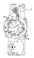
図8には、本発明の光量調節装置の第2の実施形態としての虹彩絞り装置を分解して示している。第1の実施形態では、第2の絞り羽根4を複数の第1の絞り羽根5に対してベース部材1側およびその反対側のうち一方にて重なるように配置した場合について説明した。本実施形態では、少なくとも1枚の第1の絞り羽根4と第2の絞り羽根5の間に、第3の絞り羽根12を配置している。
(Second Embodiment)
FIG. 8 is an exploded view of an iris diaphragm device as a second embodiment of the light amount adjusting device of the present invention. In 1st Embodiment, the case where the
第3の絞り羽根12は、少なくとも最小絞り状態では、固定開口1aを横断せず、その先端部12eは光軸方向でベース部材1に重ならない。また、第3の絞り羽根12は、第1の絞り羽根5のような支持部を持たない。
The
第2の絞り羽根4および第1の絞り羽根5により、絞り羽根の反りや倒れを制限できる。また、第3の絞り羽根12は、形状面積が第1の絞り羽根および第2の絞り羽根に比べ小さいため、絞り羽根同士の摺動抵抗が少なく、作動に有効である。
The
(第3の実施形態)
図9には、本発明の光量調節装置の第3の実施形態としての虹彩絞り装置を分解して示している。第1の実施形態では、第2の絞り羽根4を複数の第1の絞り羽根5に対してベース部材1側およびその反対側のうち一方にて重なるように配置した場合について説明したが、本実施形態では、第2の絞り羽根5のみを配置している。絞り羽根5が有する支持部5fにより、絞り羽根の反りや倒れを制限することができる。
(Third embodiment)
FIG. 9 is an exploded view showing an iris diaphragm device as a third embodiment of the light amount adjusting device of the present invention. In the first embodiment, a case has been described in which the
(第4の実施形態)
図5には、第1、又は第2、又は第3の実施形態において説明した絞り装置を搭載した光学機器の例としての撮像装置を示している。符号1,3,4,5,6はそれが付された部材が、第1の実施形態にて同符号を付した部材であることを示している。
(Fourth embodiment)
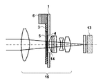
FIG. 5 shows an imaging apparatus as an example of an optical apparatus on which the diaphragm device described in the first, second, or third embodiment is mounted.
被写体からの光は撮影光学系15に入射し、撮影光学系15に含まれる絞り装置の絞り開口を通過して、CCDセンサやCMOSセンサ等により構成される撮像素子13上に被写体像を形成する。撮像素子13は、被写体像を光電変換して撮像信号を出力する。撮像装置は、この撮像信号から映像信号を生成し、この映像信号を記録したり表示したりする。
Light from the subject enters the photographing
第1乃至第3の実施形態の絞り装置では、複数の第1の絞り羽根5のベース部材1側への反りを第2の絞り羽根4によって制限しているので、撮影光学系15において絞り装置に隣接するレンズ14を絞り羽根4,5に近接する位置に配置することができる。このため、図10に示すように絞り羽根105の反りが発生した従来の絞り装置を用いる場合に比べて、撮影光学系15や撮像装置を小型化することができる。
In the aperture devices of the first to third embodiments, the warping of the plurality of
なお、第1及び第2の実施形態で説明した絞り装置は、本実施形態で説明したような撮像装置に限らず、交換レンズ等の他の光学機器にも搭載することができる。 The diaphragm device described in the first and second embodiments can be mounted not only on the imaging device described in this embodiment but also in other optical devices such as an interchangeable lens.
なお、以上説明した各実施形態は代表的な例にすぎず、本発明の実施に際しては、各実施形態に対して種々の変形や変更が可能である。 Each embodiment described above is only a representative example, and various modifications and changes can be made to each embodiment in carrying out the present invention.
良好な絞り開口形状を有する小型の光量調節装置およびこれを搭載した小型の光学機器を提供できる。 It is possible to provide a small light amount adjusting device having a favorable aperture opening shape and a small optical device equipped with the same.
1 ベース部材
3 駆動リング
4 第2の絞り羽根
5 第1の絞り羽根
6 羽根駆動部
7 仕切り板
8 NDフィルタ
9 フィルタ保持板
11 ケース
12 第3の絞り羽根
13 撮像素子
14 レンズ
DESCRIPTION OF
Claims (14)
前記開口部内に向けて回動する複数の光量調節羽根とを備え、
前記複数の光量調節羽根は、羽根の回動方向先端部が前記開口部内に位置するときに回動方向後端部が前記開口部の縁部に重なる非横断型回動羽根を含むことを特徴とする光量調節装置。 A light passage opening forming member that forms an opening through which light passes; and
A plurality of light quantity adjustment blades rotating into the opening,
The plurality of light quantity adjustment blades include a non-transverse rotation blade whose rotation direction rear end portion overlaps an edge of the opening portion when the rotation direction front end portion of the blade is positioned in the opening portion. Light quantity adjustment device.
前記光の進行方向である光軸方向において部分的に重なり合って前記固定開口を絞る絞り開口を形成し、前記ベース部材に対して回動して前記絞り開口を変化させる複数の絞り羽根とを有し、
前記複数の絞り羽根は、
少なくとも前記絞り開口が最小である最小絞り状態において、各絞り羽根のうち前記ベース部材に対する回動中心側とは反対側の端部である先端部が、前記光軸方向に前記ベース部材に重ならず、前記回動中心側及び前記先端部とは別の支持部で前記ベース部材と重なる複数の第1の絞り羽根と、
少なくとも前記最小絞り状態において、各絞り羽根のうち前記ベース部材に対する回動中心側とは反対側の端部である先端部が、前記光軸方向に前記ベース部材に重なる複数の第2の絞り羽根とを含み、
前記第2の絞り羽根が、前記第1の絞り羽根に対して、前記光軸方向のうち前記ベース部材に近い側およびその反対側のうち少なくとも一方において重なっていることを特徴とする光量調節装置。 A base member having a fixed opening through which light passes;
A plurality of aperture blades that overlap with each other in the optical axis direction, which is the traveling direction of the light, form an aperture aperture that limits the fixed aperture, and rotate relative to the base member to change the aperture aperture. And
The plurality of diaphragm blades are:
At least in the minimum aperture state in which the aperture opening is minimum, the tip of each aperture blade, which is the end opposite to the rotation center side with respect to the base member, overlaps the base member in the optical axis direction. A plurality of first diaphragm blades that overlap the base member at a support portion different from the rotation center side and the tip portion;
At least in the minimum aperture state, a plurality of second aperture blades in which the tip portion of each aperture blade that is the end opposite to the rotation center side with respect to the base member overlaps the base member in the optical axis direction Including
The second diaphragm blade overlaps the first diaphragm blade on at least one of the side close to the base member and the opposite side in the optical axis direction. .
前記光の進行方向である光軸方向において部分的に重なり合って前記固定開口を絞る絞り開口を形成し、前記ベース部材に対して回動して前記絞り開口を変化させる複数の絞り羽根とを有し、
前記複数の絞り羽根のそれぞれは、前記ベース部材に対する回動中心側とは反対側の端部である回動方向の先端部が、前記光軸方向に前記ベース部材に重ならず、回動方向の後端側であって前記回動中心側及び前記先端部とは別の支持部で前記ベース部材と重なる非横断型回動羽根であることを特徴とする光量調節装置。 A base member having a fixed opening through which light passes;
A plurality of aperture blades that overlap with each other in the optical axis direction, which is the traveling direction of the light, form an aperture aperture that limits the fixed aperture, and rotate relative to the base member to change the aperture aperture. And
Each of the plurality of aperture blades has a rotation direction tip that is an end opposite to the rotation center side with respect to the base member, and does not overlap the base member in the optical axis direction. A light amount adjusting device, characterized in that the light amount adjusting device is a non-transverse rotating blade that overlaps the base member at a support portion different from the rotation center side and the tip portion on the rear end side.
前記光の進行方向である光軸方向において部分的に重なり合って前記固定開口を絞る絞り開口を形成し、前記ベース部材に対して回動して前記絞り開口を変化させる複数の絞り羽根とを有し、
前記複数の絞り羽根は、
少なくとも前記絞り開口が最小である最小絞り状態において、各絞り羽根のうち前記ベース部材に対する回動中心側とは反対側の端部である先端部が、前記光軸方向に前記ベース部材に重ならず、前記回動中心側及び前記先端部とは別の支持部で前記ベース部材と重なる少なくとも1枚の第1の絞り羽根と、
少なくとも前記最小絞り状態において、各絞り羽根のうち前記ベース部材に対する回動中心側とは反対側の端部である先端部が、前記光軸方向に前記ベース部材に重なる少なくとも1枚の第2の絞り羽根と、
少なくとも前記絞り開口が最小である最小絞り状態において、各絞り羽根のうち前記ベース部材に対する回動中心側とは反対側の端部である先端部が、前記光軸方向に前記ベース部材に重ならず、前記回動中心側及び前記先端部とは別の支持部を持たない少なくとも1枚の第3の絞り羽根とを含むことを特徴とする光量調節装置。 A base member having a fixed opening through which light passes;
A plurality of aperture blades that overlap with each other in the optical axis direction, which is the traveling direction of the light, form an aperture aperture that limits the fixed aperture, and rotate relative to the base member to change the aperture aperture. And
The plurality of diaphragm blades are:
At least in the minimum aperture state in which the aperture opening is minimum, the tip of each aperture blade, which is the end opposite to the rotation center side with respect to the base member, overlaps the base member in the optical axis direction. The at least one first diaphragm blade that overlaps the base member at a support portion different from the rotation center side and the tip portion,
At least in the minimum aperture state, at least one second end portion of each aperture blade, which is the end opposite to the rotation center side of the base member, overlaps the base member in the optical axis direction. Aperture blades,
At least in the minimum aperture state in which the aperture opening is minimum, the tip of each aperture blade, which is the end opposite to the rotation center side with respect to the base member, overlaps the base member in the optical axis direction. And a light amount adjusting device including at least one third diaphragm blade not having a support part separate from the rotation center side and the tip part.
Priority Applications (1)
| Application Number | Priority Date | Filing Date | Title |
|---|---|---|---|
| JP2013084305A JP2014206650A (en) | 2013-04-12 | 2013-04-12 | Light quantity adjusting device, optical instrument, and imaging apparatus |
Applications Claiming Priority (1)
| Application Number | Priority Date | Filing Date | Title |
|---|---|---|---|
| JP2013084305A JP2014206650A (en) | 2013-04-12 | 2013-04-12 | Light quantity adjusting device, optical instrument, and imaging apparatus |
Publications (2)
| Publication Number | Publication Date |
|---|---|
| JP2014206650A true JP2014206650A (en) | 2014-10-30 |
| JP2014206650A5 JP2014206650A5 (en) | 2016-06-02 |
Family
ID=52120229
Family Applications (1)
| Application Number | Title | Priority Date | Filing Date |
|---|---|---|---|
| JP2013084305A Pending JP2014206650A (en) | 2013-04-12 | 2013-04-12 | Light quantity adjusting device, optical instrument, and imaging apparatus |
Country Status (1)
| Country | Link |
|---|---|
| JP (1) | JP2014206650A (en) |
Cited By (1)
| Publication number | Priority date | Publication date | Assignee | Title |
|---|---|---|---|---|
| WO2021096336A1 (en) * | 2019-11-12 | 2021-05-20 | 엘지이노텍 주식회사 | Aperture set and aperture set driving device |
Citations (5)
| Publication number | Priority date | Publication date | Assignee | Title |
|---|---|---|---|---|
| JPH1138467A (en) * | 1997-07-22 | 1999-02-12 | Matsushita Electric Ind Co Ltd | Diaphragm device, lens barrel using the same and assembling method for the lens barrel |
| JP2001033844A (en) * | 1999-07-15 | 2001-02-09 | Olympus Optical Co Ltd | Exposure adjusting device and electronic camera using the same |
| JP2006053409A (en) * | 2004-08-13 | 2006-02-23 | Nisca Corp | Optical quantity adjusting device and imaging apparatus using the same |
| JP2006154312A (en) * | 2004-11-29 | 2006-06-15 | Seiko Precision Inc | Sector driving device |
| JP2010281970A (en) * | 2009-06-03 | 2010-12-16 | Olympus Imaging Corp | Diaphragm device |
-
2013
- 2013-04-12 JP JP2013084305A patent/JP2014206650A/en active Pending
Patent Citations (5)
| Publication number | Priority date | Publication date | Assignee | Title |
|---|---|---|---|---|
| JPH1138467A (en) * | 1997-07-22 | 1999-02-12 | Matsushita Electric Ind Co Ltd | Diaphragm device, lens barrel using the same and assembling method for the lens barrel |
| JP2001033844A (en) * | 1999-07-15 | 2001-02-09 | Olympus Optical Co Ltd | Exposure adjusting device and electronic camera using the same |
| JP2006053409A (en) * | 2004-08-13 | 2006-02-23 | Nisca Corp | Optical quantity adjusting device and imaging apparatus using the same |
| JP2006154312A (en) * | 2004-11-29 | 2006-06-15 | Seiko Precision Inc | Sector driving device |
| JP2010281970A (en) * | 2009-06-03 | 2010-12-16 | Olympus Imaging Corp | Diaphragm device |
Cited By (2)
| Publication number | Priority date | Publication date | Assignee | Title |
|---|---|---|---|---|
| WO2021096336A1 (en) * | 2019-11-12 | 2021-05-20 | 엘지이노텍 주식회사 | Aperture set and aperture set driving device |
| US11796892B2 (en) | 2019-11-12 | 2023-10-24 | Lg Innotek Co., Ltd. | Aperture set and aperture set driving device |
Similar Documents
| Publication | Publication Date | Title |
|---|---|---|
| US7473042B2 (en) | Light-amount adjusting apparatus | |
| WO2014136457A1 (en) | Light-amount adjustment apparatus, optical device, and imaging apparatus | |
| JP5938405B2 (en) | Light amount adjusting device and optical apparatus | |
| JP2006053409A (en) | Optical quantity adjusting device and imaging apparatus using the same | |
| US20160139491A1 (en) | Diaphragm device and optical instrument | |
| JP2016099377A (en) | Diaphragm device and optical apparatus | |
| JP6426436B2 (en) | Blade driving device, light amount adjusting device, and imaging device | |
| JP2012145929A (en) | Light quantity adjustment device and optical instrument | |
| JP2013029693A (en) | Light amount control device and optical apparatus | |
| JP6166262B2 (en) | Light amount adjusting device and optical apparatus | |
| JP6068903B2 (en) | Aperture device and imaging device | |
| JP2014206650A (en) | Light quantity adjusting device, optical instrument, and imaging apparatus | |
| JP2013097178A (en) | Light quantity adjustment device and optical equipment | |
| JP6345026B2 (en) | Aperture device, lens device and imaging device having the same | |
| JP5825783B2 (en) | Lens barrel and imaging device | |
| JP6346409B2 (en) | Light amount adjusting device and imaging device | |
| JP6918502B2 (en) | Blade drive | |
| JP6494581B2 (en) | Aperture device, lens device and imaging device having the same | |
| JP3550963B2 (en) | Camera aperture mechanism | |
| JP6647051B2 (en) | Light control device | |
| JP2021021802A (en) | Diaphragm device and lens device and imaging device including the same | |
| JP5121812B2 (en) | Lens barrier device | |
| JP5952155B2 (en) | Aperture device and lens barrel | |
| JP2002341223A (en) | Zoom lens barrel | |
| JP6977856B2 (en) | Aperture adjustment device, lens barrel and optical equipment |
Legal Events
| Date | Code | Title | Description |
|---|---|---|---|
| A521 | Written amendment |
Free format text: JAPANESE INTERMEDIATE CODE: A523 Effective date: 20160411 |
|
| A621 | Written request for application examination |
Free format text: JAPANESE INTERMEDIATE CODE: A621 Effective date: 20160411 |
|
| A977 | Report on retrieval |
Free format text: JAPANESE INTERMEDIATE CODE: A971007 Effective date: 20170118 |
|
| A131 | Notification of reasons for refusal |
Free format text: JAPANESE INTERMEDIATE CODE: A131 Effective date: 20170224 |
|
| A521 | Written amendment |
Free format text: JAPANESE INTERMEDIATE CODE: A523 Effective date: 20170420 |
|
| A131 | Notification of reasons for refusal |
Free format text: JAPANESE INTERMEDIATE CODE: A131 Effective date: 20170929 |
|
| A521 | Written amendment |
Free format text: JAPANESE INTERMEDIATE CODE: A523 Effective date: 20171127 |
|
| A02 | Decision of refusal |
Free format text: JAPANESE INTERMEDIATE CODE: A02 Effective date: 20180406 |