JP2014206355A - Portable temperature controller - Google Patents
Portable temperature controller Download PDFInfo
- Publication number
- JP2014206355A JP2014206355A JP2013085545A JP2013085545A JP2014206355A JP 2014206355 A JP2014206355 A JP 2014206355A JP 2013085545 A JP2013085545 A JP 2013085545A JP 2013085545 A JP2013085545 A JP 2013085545A JP 2014206355 A JP2014206355 A JP 2014206355A
- Authority
- JP
- Japan
- Prior art keywords
- casing
- air
- evaporator
- condenser
- blowing
- Prior art date
- Legal status (The legal status is an assumption and is not a legal conclusion. Google has not performed a legal analysis and makes no representation as to the accuracy of the status listed.)
- Granted
Links
Images

Landscapes
- Air-Conditioning Room Units, And Self-Contained Units In General (AREA)
Abstract
Description
本発明は、冷凍サイクルの蒸発器によって空気を冷却して供給対象に供給可能に構成された可搬型温調装置に関するものである。 The present invention relates to a portable temperature control device configured to cool air with an evaporator of a refrigeration cycle and supply it to a supply target.
この種の可搬型温調装置として、特開2000−55401号公報に背嚢型充電可能エア・コンディショナー(以下、「背嚢型エアコン」ともいう)が開示されている。この背嚢型エアコンは、一対のベルトが取り付けられた背嚢型ハウジング(以下、「ハウジング」ともいう)内に冷凍サイクルの各構成要素や送風用のファンが収容されて、冷凍サイクルによって冷却した空気を、ハウジングに接続されている冷風ダクトを介して利用者のヘルメット内に供給可能に構成されている。 As this type of portable temperature control device, Japanese Patent Application Laid-Open No. 2000-55401 discloses a back sac type chargeable air conditioner (hereinafter also referred to as “back sac type air conditioner”). In this back sac type air conditioner, each component of the refrigeration cycle and a fan for blowing air are housed in a back sac type housing (hereinafter also referred to as “housing”) to which a pair of belts are attached. It is configured to be supplied into the user's helmet through a cold air duct connected to the housing.
この場合、この背嚢型エアコンでは、蒸発器および第1ファンなどを収容する室内部がハウジングの内部空間における上方部位に区画されると共に、コンデンサー、第2ファン、コンプレッサーおよび冷媒タンクなどを収容する室外部がハウジングの内部空間における下方部位に区画されている。これにより、この背嚢型エアコンでは、蒸発器によって冷却した室内部内の空気が、コンデンサーやコンプレッサー等の発熱体から発せられる熱によって温度上昇させられた室外部内の空気と混ざり合うことなく、冷風ダクトを介してヘルメット内に供給される。 In this case, in this back sac-type air conditioner, the interior of the housing that houses the evaporator, the first fan, and the like is partitioned into an upper portion in the internal space of the housing, and the chamber that houses the condenser, the second fan, the compressor, the refrigerant tank, and the like. The outside is partitioned into a lower part in the internal space of the housing. Thereby, in this back sac type air conditioner, the air inside the room cooled by the evaporator does not mix with the air inside the room raised in temperature by the heat emitted from the heating element such as a condenser or a compressor, and the cold air duct It is supplied in the helmet through.
ところが、従来の背嚢型エアコンには、以下の解決すべき問題点が存在する。すなわち、従来の背嚢型エアコンでは、ハウジングの上方部位に区画された室内部に蒸発器等が収容され、かつハウジングの下方部位に区画された室外部にコンデンサー等が収容されている。この場合、背嚢状の可搬体(人が背負って搬送するもの)では、重量物が上方部位に配置されている状態よりも、重量物が下方部位に配置されている状態の方が重く感じられることが知られている。したがって、冷凍サイクルの構成要素の中でも比較的重いコンデンサーが、ハウジングの下方部位に配設されている従来の背嚢型エアコンには、背嚢型エアコンの搬送時に利用者にかかる負担が大きいという問題点が存在する。 However, the conventional back sac type air conditioner has the following problems to be solved. That is, in the conventional back sac-type air conditioner, an evaporator or the like is accommodated in an indoor portion partitioned in an upper portion of the housing, and a condenser or the like is accommodated in an outdoor portion partitioned in a lower portion of the housing. In this case, in a back sac-like portable body (one that is carried on a person's back), the state in which the heavy object is disposed in the lower part is heavier than the state in which the heavy object is disposed in the upper part. It is known that Therefore, the conventional back sac type air conditioner in which a relatively heavy condenser among the components of the refrigeration cycle is disposed in the lower part of the housing has a problem that the burden on the user is large when the back sac type air conditioner is transported. Exists.
また、従来の背嚢型エアコンでは、冷風ダクトが接続される透孔がハウジングの天板に設けられると共に、室内部(ハウジング内)において蒸発器によって冷却した空気を上方に送気して透孔から冷風ダクト内に送風する構成が採用されている。この場合、ファン等によって強制的に移動させられることのない自然状態において、周囲の空気よりも低温の空気(冷気)は、下降気流となって下向きに移動する。しかしながら、従来の背嚢型エアコンでは、蒸発器によって冷却した空気を上方に送気する構成が採用されており、冷気の移動方向が自然状態における上記の冷気の流れと逆行するため、冷気の送風効率が低下しているという問題点がある。 Further, in the conventional back sac-type air conditioner, a through hole to which a cold air duct is connected is provided in the top plate of the housing, and air cooled by an evaporator in the indoor portion (inside the housing) is sent upward from the through hole. The structure which ventilates in a cold wind duct is employ | adopted. In this case, in a natural state that is not forcibly moved by a fan or the like, air (cold air) having a temperature lower than that of the surrounding air moves downward as a descending airflow. However, the conventional back sac type air conditioner employs a configuration in which the air cooled by the evaporator is sent upward, and the moving direction of the cold air is opposite to the flow of the cold air in the natural state. There is a problem that is reduced.
さらに、従来の背嚢型エアコンでは、コンデンサーやコンプレッサー等の発熱体がハウジングの下方部位に区画された室外部に収容されている。この場合、ファン等によって強制的に移動させられることのない自然状態において、周囲の空気よりも高温の空気は上昇気流となって上向きに移動する。しかしながら、従来の背嚢型エアコンでは、発熱体が収容されている室外部の上方に室内部が区画されているため、室外部内の温度上昇した空気を上向きに移動させてハウジングの外部に送風することができない。このため、従来の背嚢型エアコンでは、コンデンサーやコンプレッサー等の発熱体からの熱の排熱効率が低下しており、これに起因して、蒸発器による空気の冷却効率も低下しているという問題点がある。 Furthermore, in the conventional back sac-type air conditioner, a heating element such as a condenser or a compressor is accommodated outside the room defined in the lower part of the housing. In this case, in a natural state where the air is not forcibly moved by a fan or the like, the air having a temperature higher than that of the surrounding air moves upward as an ascending current. However, in the conventional back sac type air conditioner, since the indoor part is partitioned above the outside of the room in which the heating element is accommodated, the air whose temperature has risen inside the outside is moved upward and blown outside the housing. I can't. For this reason, in the conventional back sac type air conditioner, the heat exhaust efficiency of the heat from a heating element such as a condenser or a compressor is lowered, and as a result, the cooling efficiency of the air by the evaporator is also lowered. There is.
本発明は、かかる解決すべき問題点に鑑みてなされたものであり、空気の冷却効率、および冷却した空気の送風効率を向上させつつ、搬送時に利用者にかかる負担を軽減し得る可搬型温調装置を提供することを主目的とする。 The present invention has been made in view of the problems to be solved, and is a portable temperature capable of reducing the burden on the user during transportation while improving the cooling efficiency of air and the blowing efficiency of cooled air. The main purpose is to provide a control device.
上記目的を達成すべく、請求項1記載の可搬型温調装置は、圧縮機、凝縮器、膨張弁および蒸発器を有する冷凍サイクルと、前記冷凍サイクルを収容するケーシングと、前記ケーシング内に導入されて前記蒸発器によって温度低下させられた空気を当該ケーシングの外部に送風する第1送風処理、および前記ケーシングの外部の空気を当該ケーシング内に導入して前記蒸発器に送風することで当該蒸発器によって温度低下させられた空気を当該ケーシングの外部に送風する第2送風処理のいずれかを実行可能に当該ケーシングに配設された送風機とを備え、前記ケーシングには、当該ケーシングの外部の空気を当該ケーシング内に導入する吸気口と、前記蒸発器によって温度低下させられた空気を当該ケーシングの外部に送風する第1送風口と、前記圧縮機および前記凝縮器によって温度上昇させられた空気を当該ケーシングの外部に送風する第2送風口とが形成されると共に、前記蒸発器によって温度低下させられた空気を前記第1送風口に案内する空気流路が当該ケーシング内に形成され、前記冷凍サイクルは、少なくとも前記蒸発器および前記凝縮器が前記ケーシング内の上方部位に収容され、前記第1送風口は、前記ケーシングにおける上方部位よりも下方に位置する下方部位に形成され、前記第2送風口は、前記ケーシングにおける上方部位に形成されている。
In order to achieve the above object, a portable temperature control device according to
請求項2記載の可搬型温調装置は、請求項1記載の可搬型温調装置において、前記冷凍サイクルを動作させる電源としてのバッテリーを備え、前記バッテリーは、前記ケーシング内の下方部位に収容されている。
The portable temperature control device according to
請求項3記載の可搬型温調装置は、請求項1または2記載の可搬型温調装置において、前記ケーシングには、当該可搬型温調装置を背負うためのベルトが取り付けられている。
The portable temperature control apparatus according to
請求項4記載の可搬型温調装置は、請求項3記載の可搬型温調装置において、前記ケーシングは、当該ケーシングにおける下方部位の横幅が、前記蒸発器および前記凝縮器が収容されている上方部位の横幅よりも狭くなるように形成されている。
The portable temperature control device according to claim 4 is the portable temperature control device according to
請求項5記載の可搬型温調装置は、請求項3または4記載の可搬型温調装置において、前記冷凍サイクルの動作開始および動作停止を指示するための操作スイッチが前記ベルトに配設されている。
The portable temperature control device according to
請求項1記載の可搬型温調装置によれば、少なくとも蒸発器および凝縮器をケーシング内の上方部位に収容すると共に、蒸発器によって温度低下させられた空気をケーシングの外部に送風する第1送風口をケーシングにおける下方部位に形成し、かつ、圧縮機および凝縮器によって温度上昇させられた空気をケーシングの外部に送風する第2送風口をケーシングにおける上方部位に形成したことにより、重量物である凝縮器や蒸発器をケーシングの上方部位に収容したことで、実際の重量よりも軽く感じられるため、この可搬型温調装置を背負った利用者の負担を十分に軽減することができるだけでなく、圧縮機や凝縮器によって温度上昇させられた空気が上昇気流となって第2送風口からスムースに送風されるため、冷凍サイクルの運転効率、すなわち、蒸発器による空気の冷却効率を十分に向上させることができると共に、蒸発器によって冷却された空気が下降気流となって空気流路を下降して第1送風口からスムースに送風されるため、ケーシングの外部への冷気の送風効率を十分に向上させることができる。
According to the portable temperature control device of
また、請求項2記載の可搬型温調装置によれば、ケーシング内の下方部位にバッテリーを収容したことにより、凝縮器や蒸発器を収容したことで冷媒配管が引き回され、かつ冷気の送風に適した空気流路を形成する必要があるケーシング内の上方部位にバッテリーを収容する構成とは異なり、バッテリーの収容空間を確保するために、冷媒配管を必要以上に長く引き回したり、空気の流れが妨げられるような空気流路を形成したりすることなく、バッテリーを収容することができる。これにより、冷凍サイクルの冷媒圧送効率をさらに向上させ、かつ空気の送風効率をさらに向上させることができる。
According to the portable temperature control apparatus of
さらに、請求項3記載の可搬型温調装置によれば、可搬型温調装置を背負うためのベルトをケーシングに取り付けたことにより、例えば手提げ用の取っ手をケーシングに設けて可搬型温調装置を搬送する構成とは異なり、可搬型温調装置を背負った利用者の両手が自由となるため、可搬型温調装置を背負ったままで各種の作業を実施することができる。
Furthermore, according to the portable temperature control device of
また、請求項4記載の可搬型温調装置によれば、ケーシングにおける下方部位の横幅が上方部位の横幅よりも狭くなるようにケーシングを形成したことにより、凝縮器や蒸発器が収容されている上方部位の左右両端部の下方(下方部位の左方および右方)にスペースが形成されるため、利用者の肘などがケーシングに当接する不具合を生じさせることなく可搬型温調装置を背負って移動することができる。 According to the portable temperature control apparatus of claim 4, the condenser and the evaporator are accommodated by forming the casing such that the lateral width of the lower part of the casing is narrower than the lateral width of the upper part. Since a space is formed below the left and right ends of the upper part (left and right of the lower part), the portable temperature control device can be carried on the back without causing a problem that the user's elbow or the like comes into contact with the casing. Can move.
さらに、請求項5記載の可搬型温調装置によれば、冷凍サイクルの動作開始および動作停止を指示するための操作スイッチをベルトに配設したことにより、背負った状態の可搬型温調装置におけるケーシングに手を伸ばす不自然な操作姿勢を強いられることなく、圧縮機等の動作状態を任意に切り替えることができる。
Furthermore, according to the portable temperature control device of
以下、添付図面を参照して、本発明に係る可搬型温調装置の実施の形態について説明する。 Embodiments of a portable temperature control device according to the present invention will be described below with reference to the accompanying drawings.
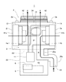
図1に示すバックパッククーラー1は、「可搬型温調装置」の一例であって、ケーシング2、冷凍サイクル3、ファン4a,4b、バッテリー5および制御回路部6を備え、冷凍サイクル3によって冷却した空気を図示しないエアホースを介して供給対象に供給可能に構成されている。この場合、冷凍サイクル3は、圧縮機11、凝縮器12、膨張弁13および蒸発器14を備え、後述するように、制御回路部6の制御下で圧縮機11が冷媒を圧縮することにより、蒸発器14の周囲の空気が冷却されるように構成されている。なお、本例のバックパッククーラー1(冷凍サイクル3)では、一例として、キャピラリチューブで構成された膨張弁13を採用しているが、この膨張弁13に代えて電子膨張弁を「膨張弁」として採用することもできる。また、冷媒としてフロンガスを使用する例について説明するが、二酸化炭素(CO2)などの各種の冷媒ガスを使用する構成を採用することもができる。
A
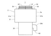
一方、ケーシング2は、冷凍サイクル3、ファン4a,4b、バッテリー5および制御回路部6等を収容可能に構成されたケーシング本体2aと、このバックパッククーラー1を背負って搬送可能にケーシング本体2aに取り付けられた一対のベルト2bとを備えている。また、ケーシング本体2aは、冷凍サイクル3における凝縮器12、膨張弁13および蒸発器14やファン4a,4bなどを収容する上方収容空間S1(「ケーシング内の上方部位」の一例)を形成する上側収容部21(「ケーシングにおける上方部位」の一例)と、冷凍サイクル3における圧縮機11や、バッテリー5および制御回路部6などを収容する下方収容空間S2(「ケーシング内の下方部位」の一例)を形成する下側収容部22(「ケーシングにおける下方部位」の一例)とが一体的に形成されている。
On the other hand, the
この場合、上側収容部21と下側収容部22との間には、上方収容空間S1および下方収容空間S2を区画すると共に凝縮器12や蒸発器14を固定するためのベース部として機能する仕切部23が設けられている。また、図1,2に示すように、本例のバックパッククーラー1(ケーシング2)では、下側収容部22の横幅が上側収容部21の横幅よりも狭くなるように(上側収容部21の横幅が下側収容部22の横幅よりも広くなるように)正面視T字状に形成されている。なお、本明細書においては、バックパッククーラー1が利用者によって背負われた状態において、利用者の背後から見える面を正面とし、かつ、利用者の背中に接する面を背面として、以下に説明する。
In this case, the upper storage space S1 and the lower storage space S2 are partitioned between the
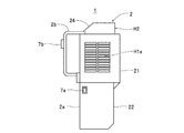
また、図3に示すように、上側収容部21の左右両側面の一方(一例として、正面向かって左側の側面)には、後述するように凝縮器12を冷却するための空気をケーシング2の外部から上方収容空間S1に導入するための吸気口H1aが形成されている。さらに、図4に示すように、上側収容部21の左右両側面の他方(一例として、正面向かって右側の側面)には、後述するように蒸発器14によって冷却して供給対象に供給するための空気をケーシング2の外部から上方収容空間S1に導入するための吸気口H1b(「吸気口」の一例)が形成されている。また、図1,2に示すように、上側収容部21の天板には、後述するように圧縮機11や凝縮器12からの排熱によって温度上昇した(圧縮機11や凝縮器12によって温度上昇させられた)ケーシング2内の空気(上方収容空間S1内の空気)をケーシング2の外部に送風するための送風口H2(「第2送風口」の一例)が設けられたダクト24が配設されている(「第2送風口」が「ケーシングにおける上方部位に形成されている」との構成の一例)。
As shown in FIG. 3, air for cooling the
さらに、図1,2,4に示すように、下側収容部22の左右両側面の一方(一例として、正面向かって右側の側面)には、ダクト25bが取り付けられている。また、図1に示すように、ケーシング2内には、上側収容部21内(上方収容空間S1内)に収容されている蒸発器14と下側収容部22に取り付けられたダクト25bとを相互に接続するようにダクト25aが配設されている。この場合、本例のバックパッククーラー1(ケーシング2)では、ダクト25bの送風口H3が「第1送風口」に相当する(「第1送風口」が「ケーシングにおける下方部位に形成され」との構成の一例)。また、本例のバックパッククーラー1(ケーシング2)では、上記の両ダクト25a,25bが相俟って「空気流路」の一例である空気流路Rが構成されている。これにより、本例のバックパッククーラー1(ケーシング2)では、後述するように、吸気口H1bから上方収容空間S1内に導入されて蒸発器14によって温度低下させられた空気が空気流路Rを経て送風口H3からケーシング2の外部に送風される。
Further, as shown in FIGS. 1, 2, and 4, a
また、図3に示すように、ケーシング2の上側収容部21における左右両側面の他方(一例として、正面向かって左側の側面)には、主電源スイッチを有する操作部7aが配設されている。さらに、本例のバックパッククーラー1(ケーシング2)では、上記の操作部7aにおける主電源スイッチがオン状態に操作されている状態において、冷凍サイクル3の圧縮機11やファン4a,4bの動作開始および動作停止を指示したり、圧縮機11の運転状態(冷媒の圧縮量)を変更するためのオン/オフスイッチを有する操作部7b(「操作スイッチ」の一例)がベルト2bに配設されている。また、本例のバックパッククーラー1(ケーシング2)では、一例として、下側収容部22の背面における下方側に、後述するように下方収容空間S2内に収容されているバッテリー5を脱着するため開口部が設けられると共に、この開口部が蓋体によって閉塞されている(図示せず)。
As shown in FIG. 3, an
ファン4aは、図1示すように、凝縮器12に取り付けられており、吸気口H1aからケーシング2内(上方収容空間S1内)に空気を吸気することで凝縮器12を冷却する。この場合、本例のバックパッククーラー1では、このファン4aが吸気口H1aからケーシング2の外部の空気を吸気することにより、上方収容空間S1や下方収容空間S2における空気流路Rを除く部位の空気がダクト24の送風口H2からケーシング2の外部に送風される構成が採用されている。なお、本例のバックパッククーラー1のような構成に代えて、吸気口H1aと凝縮器12との間にファン4aを配置してケーシング2の外部の空気を凝縮器12に送風する構成を採用することもできる。
As shown in FIG. 1, the
ファン4bは、「送風機」の一例であって、後述するように、吸気口H1bからケーシング2内(上方収容空間S1内)に導入されて蒸発器14によって温度低下させられた空気を、ダクト25a,25b(空気流路R)を介して送風口H3からケーシング2の外部に送風する(供給対象に供給する)送風処理(「第1送風処理」の一例)を実行可能に蒸発器14に取り付けられている。なお、上記のような構成に代えて、吸気口H1bと蒸発器14との間、または、吸気口H1bの外側(ケーシング2の外部)にファン4bを配置し、ケーシング2の外部の空気を吸気口H1bからケーシング2内(上方収容空間S1内)に導入して蒸発器14に送風することにより、蒸発器14によって温度低下させられた空気を、空気流路Rを介して送風口H3からケーシング2の外部に送風する(供給対象に供給する)送風処理(「第2送風処理」の一例)を実行可能に構成することもできる。
The
バッテリー5は、冷凍サイクル3(圧縮機11)、ファン4a,4bおよび制御回路部6を動作させるための電源であって、一例として、リチウムイオン二次電池等の二次電池で構成され、前述したように、下側収容部22内(下方収容空間S2)に収容されている。制御回路部6は、冷凍サイクル3の圧縮機11やファン4a,4bの動作を制御する。具体的には、制御回路部6は、圧縮機11の動作状態を変更するためのインバータ制御回路や、ファン4a,4bを動作させるための電圧を生成する(変圧する)変圧回路等を備え(図示せず)、操作部7a,7bの操作状態に応じて、圧縮機11やファン4a,4bの動作開始や動作停止、および圧縮機11の運転状態(冷媒の圧縮量)の変更を制御する。
The
このバックパッククーラー1は、一例として、エアホースを接続可能な接続口が配設されたカバーオール(図示せず)を着た利用者が、バックパッククーラー1のダクト25b(送風口H3)とカバーオールにおける上記の接続口とをエアーホースによって相互に接続した状態においてバックパッククーラー1を背負うことにより、利用者の移動を規制することなく、エアホースを介してカバーオール内に冷気を供給することが可能となっている。これにより、例えば、周囲温度が高温となる作業空間内や、日中の炎天下において利用者(作業者)の体温上昇を抑えることが可能となる。
In this
具体的には、まず、ダクト25b(送風口H3)とカバーオールの接続口とをエアーホースによって相互に接続する。次いで、操作部7aの主電源スイッチをオン操作する。この際には、ケーシング2内のバッテリー5が制御回路部6に接続される。続いて、ケーシング2に配設されているベルト2b,2bに両腕を通してバックパッククーラー1を背負う。この際に、本例のバックパッククーラー1では、各構成要素のなかでも重い凝縮器12や蒸発器14がケーシング2における上側収容部21内の上方収容空間S1に収容されているため、仮に、従来の背嚢型エアコンと総重量が同じであったとしても、利用者が感じる重さが十分に軽くなっている。
Specifically, first, the
次いで、操作部7bを操作して冷凍サイクル3およびファン4a,4bの動作開始を指示する。この際に、本例のバックパッククーラー1では、ベルト2bに操作部7bが配設されているため、無理な姿勢を強いられることなく操作部7bの操作スイッチを操作することが可能となっている。また、操作部7bのスイッチ操作によって動作開始を指示されたときに、制御回路部6は、圧縮機11に電源を供給して冷媒の圧縮を開始させると共に、ファン4a,4bを動作させる。
Next, the
この際には、圧縮機11によって圧縮された高温高圧の冷媒ガスが凝縮器12に圧送されると共にファン4aによってケーシング2の外部の空気が吸気口H1aから上方収容空間S1に吸気され、この空気が凝縮器12を通過する際に凝縮器12内の高温高圧の冷媒ガスと熱交換することで温度上昇させられる。また、ファン4aによってケーシング2の外部の空気が上方収容空間S1内に順次吸気されることにより、凝縮器12によって温度上昇させられた上方収容空間S1内の空気が、図1に矢印Aで示すように、ダクト24の送風口H2からケーシング2の外部に送風される。
At this time, the high-temperature and high-pressure refrigerant gas compressed by the
この際に、本例のバックパッククーラー1では、ケーシング2における上方部位に送風口H2が形成されているため、凝縮器12によって温度上昇させられた高温の空気が上昇気流となってケーシング2内(上方収容空間S1内)を上昇して、送風口H2からスムーズに送風される。また、冷凍サイクル3の動作時には、制御回路部6のインバータ制御回路や圧縮機11が発熱して高温となり、制御回路部6や圧縮機11の周囲の空気(この例では、下方収容空間S2内の空気)が温度上昇させられる。この温度上昇させられた空気は、上昇気流となってケーシング2内を上昇し、凝縮器12において温度上昇させられた空気と共に送風口H2からケーシング2の外部に送風される。
At this time, in the
一方、吸気口H1aから吸気された空気との熱交換によって凝縮器12内において凝縮させられた冷媒は、膨張弁13を通過して蒸発器14に供給される。この際には、ファン4bによってケーシング2の外部の空気が吸気口H1bから上方収容空間S1に吸気されているため、この空気が蒸発器14を通過する際に蒸発器14内の冷媒と熱交換させられることで冷却される。また、蒸発器14において空気を冷却することで温度上昇させられた冷媒は、圧縮機11に吸引されて圧縮されて、再び凝縮器12に圧送される。
On the other hand, the refrigerant condensed in the
また、蒸発器14において冷却された空気は、図1に矢印Bで示すように、空気流路Rを通過して送風口H3からエアホース内に送風されて、エアホースを介して利用者のカバーオール内に供給される。この際に、本例のバックパッククーラー1では、ケーシング2における下方部位に送風口H3が形成されているため、蒸発器14によって冷却された(温度低下させられた)低温の空気が下降気流となってケーシング2内(空気流路R内)を下降して、送風口H3からエアホース内にスムーズに送風される。これにより、利用者の身体とカバーオールとの間の空間、すなわち、利用者の身体の周囲が冷却されて、利用者の体温上昇を抑えることが可能となる。
In addition, as shown by an arrow B in FIG. 1, the air cooled in the evaporator 14 passes through the air flow path R and is blown into the air hose from the blower port H3, and then inside the user's coverall through the air hose. To be supplied. At this time, in the
このように、このバックパッククーラー1によれば、少なくとも凝縮器12および蒸発器14をケーシング2内の上方部位(上側収容部21内の上方収容空間S1)に収容すると共に、蒸発器14によって温度低下させられた空気をケーシング2の外部に送風する送風口H3をケーシング2における下方部位(下側収容部22の側板)に形成し、かつ、圧縮機11および凝縮器12によって温度上昇させられた空気をケーシング2の外部に送風する送風口H2をケーシング2における上方部位(上側収容部21上のダクト24)に形成したことにより、重量物である凝縮器12や蒸発器14をケーシング2の上方部位(上方収容空間S1)に収容したことで、実際の重量よりも軽く感じられるため、このバックパッククーラー1を背負った利用者の負担を十分に軽減することができるだけでなく、圧縮機11や凝縮器12によって温度上昇させられた空気が上昇気流となって送風口H2からスムースに送風されるため、冷凍サイクル3の運転効率、すなわち、蒸発器14による空気の冷却効率を十分に向上させることができると共に、蒸発器14によって冷却された空気が下降気流となって空気流路Rを下降して送風口H3からスムースに送風されるため、供給対象(上記の例では、利用者が着ているカバーオール内)への冷気の送風効率を十分に向上させることができる。
Thus, according to the
また、このバックパッククーラー1によれば、ケーシング2内の下方部位(下側収容部22内の下方収容空間S2)にバッテリー5を収容したことにより、凝縮器12や蒸発器14を収容したことで冷媒配管が引き回され、かつ冷気の送風に適した空気流路Rを形成する必要がある上方収容空間S1内にバッテリー5を収容する構成とは異なり、バッテリー5の収容空間を確保するために、冷媒配管を必要以上に長く引き回したり、空気の流れが妨げられるような空気流路Rを形成したりすることなく、バッテリー5を収容することができる。これにより、冷凍サイクル3の冷媒圧送効率をさらに向上させ、かつ空気(冷気)の送風効率をさらに向上させることができる。
Moreover, according to this
さらに、このバックパッククーラー1によれば、バックパッククーラー1を背負うためのベルト2b,2bをケーシング2に取り付けたことにより、例えば手提げ用の取っ手を「ケーシング」に設けて「バックパッククーラー(可搬型温調装置)」を搬送する構成とは異なり、バックパッククーラー1を背負った利用者の両手が自由となるため、バックパッククーラー1を背負ったままで各種の作業を実施することができる。
Furthermore, according to this
また、このバックパッククーラー1によれば、ケーシング2における下方部位(下側収容部22)の横幅が上方部位(上側収容部21)の横幅よりも狭くなるようにケーシング2を形成したことにより、上側収容部21の左右両端部の下方(下側収容部22の左方および右方)にスペースが形成されるため、利用者の肘などがケーシング2に当接する不具合を生じさせることなくバックパッククーラー1を背負って移動することができる。
Moreover, according to this
さらに、このバックパッククーラー1によれば、冷凍サイクルの動作開始および動作停止を指示するための操作スイッチを有する操作部7bをベルト2b,2bに配設したことにより、背負った状態のバックパッククーラー1におけるケーシング2に手を伸ばす不自然な操作姿勢を強いられることなく、圧縮機11等の動作状態を任意に切り替えることができる。
Furthermore, according to the
なお、「可搬型温調装置」の構成は、上記のバックパッククーラー1の構成に限定されるものではない。例えば、圧縮機11を下側収容部22内の下方収容空間S2に収容した例について説明したが、「圧縮機」の重量が重い場合には、この「圧縮機」を「ケーシングにおける上方部位」に収容する構成を採用することもできる。このような構成を採用することにより、利用者に対して「可搬型温調装置」の重量を一層軽く感じさせることができる。また、膨張弁13を上側収容部21内の上方収容空間S1に収容した例について説明したが、「膨張弁」は比較的軽量のため、この「膨張弁」を「ケーシングにおける下方部位」に収容する構成を採用することもできる。さらに、バッテリー5を備えて構成した例について説明したが、このような構成に代えて(または、このような構成に加えて)、圧縮機11やファン4a,4b等を動作させるための電源を外部から供給させるための電源ケーブルを接続可能に構成することもできる(図示せず)。
The configuration of the “portable temperature control device” is not limited to the configuration of the
1 バックパッククーラー
2 ケーシング
2a ケーシング本体
2b ベルト
3 冷凍サイクル
4a,4b ファン
5 バッテリー
6 制御回路部
7a,7b 操作部
11 圧縮機
12 凝縮器
13 膨張弁
14 蒸発器
21 上側収容部
22 下側収容部
23 仕切部
24,25a,25b ダクト
H1a,H1b 吸気口
H2,H3 送風口
R 空気流路
S1 上方収容空間
S2 下方収容空間
DESCRIPTION OF
Claims (5)
前記冷凍サイクルを収容するケーシングと、
前記ケーシング内に導入されて前記蒸発器によって温度低下させられた空気を当該ケーシングの外部に送風する第1送風処理、および前記ケーシングの外部の空気を当該ケーシング内に導入して前記蒸発器に送風することで当該蒸発器によって温度低下させられた空気を当該ケーシングの外部に送風する第2送風処理のいずれかを実行可能に当該ケーシングに配設された送風機とを備え、
前記ケーシングには、当該ケーシングの外部の空気を当該ケーシング内に導入する吸気口と、前記蒸発器によって温度低下させられた空気を当該ケーシングの外部に送風する第1送風口と、前記圧縮機および前記凝縮器によって温度上昇させられた空気を当該ケーシングの外部に送風する第2送風口とが形成されると共に、前記蒸発器によって温度低下させられた空気を前記第1送風口に案内する空気流路が当該ケーシング内に形成され、
前記冷凍サイクルは、少なくとも前記蒸発器および前記凝縮器が前記ケーシング内の上方部位に収容され、
前記第1送風口は、前記ケーシングにおける下方部位に形成され、
前記第2送風口は、前記ケーシングにおける上方部位に形成されている可搬型温調装置。 A refrigeration cycle having a compressor, a condenser, an expansion valve and an evaporator;
A casing containing the refrigeration cycle;
A first air blowing process for blowing air introduced into the casing and having its temperature lowered by the evaporator to the outside of the casing, and air outside the casing is introduced into the casing and blown to the evaporator. A blower disposed in the casing so as to be capable of performing any one of the second air blowing processes for blowing the air whose temperature has been lowered by the evaporator to the outside of the casing,
The casing includes an inlet for introducing air outside the casing into the casing, a first air outlet for blowing the air whose temperature has been lowered by the evaporator to the outside of the casing, the compressor, A second air outlet that blows the air whose temperature has been raised by the condenser to the outside of the casing, and an air flow that guides the air whose temperature has been lowered by the evaporator to the first air outlet. A path is formed in the casing,
In the refrigeration cycle, at least the evaporator and the condenser are accommodated in an upper part in the casing,
The first air outlet is formed in a lower part of the casing,
The second air blowing port is a portable temperature control device formed at an upper part of the casing.
前記バッテリーは、前記ケーシング内の下方部位に収容されている請求項1記載の可搬型温調装置。 A battery as a power source for operating the refrigeration cycle,
The portable temperature control device according to claim 1, wherein the battery is housed in a lower part of the casing.
Priority Applications (1)
| Application Number | Priority Date | Filing Date | Title |
|---|---|---|---|
| JP2013085545A JP6240969B2 (en) | 2013-04-16 | 2013-04-16 | Portable temperature controller |
Applications Claiming Priority (1)
| Application Number | Priority Date | Filing Date | Title |
|---|---|---|---|
| JP2013085545A JP6240969B2 (en) | 2013-04-16 | 2013-04-16 | Portable temperature controller |
Publications (2)
| Publication Number | Publication Date |
|---|---|
| JP2014206355A true JP2014206355A (en) | 2014-10-30 |
| JP6240969B2 JP6240969B2 (en) | 2017-12-06 |
Family
ID=52120034
Family Applications (1)
| Application Number | Title | Priority Date | Filing Date |
|---|---|---|---|
| JP2013085545A Active JP6240969B2 (en) | 2013-04-16 | 2013-04-16 | Portable temperature controller |
Country Status (1)
| Country | Link |
|---|---|
| JP (1) | JP6240969B2 (en) |
Cited By (3)
| Publication number | Priority date | Publication date | Assignee | Title |
|---|---|---|---|---|
| CN111263871A (en) * | 2017-07-28 | 2020-06-09 | 欧洲冷水机组有限公司 | Air condenser |
| US20210131716A1 (en) * | 2019-11-05 | 2021-05-06 | Carrier Corporation | Unit load device |
| WO2021210430A1 (en) * | 2020-04-14 | 2021-10-21 | 株式会社デンソー | Temperature control box |
Citations (7)
| Publication number | Priority date | Publication date | Assignee | Title |
|---|---|---|---|---|
| JPS6229032U (en) * | 1985-08-07 | 1987-02-21 | ||
| JPH02176326A (en) * | 1988-12-27 | 1990-07-09 | Koken Kk | Portable cooling air delivery device |
| JPH0732422U (en) * | 1993-11-05 | 1995-06-16 | 五十一 紫垣 | Portable air conditioner |
| JP2000055401A (en) * | 1998-08-07 | 2000-02-25 | Shigemi Ichikawa | Knapsack type chargeable air conditioner |
| JP2002188831A (en) * | 2000-12-18 | 2002-07-05 | Masazo Matsui | Back cooling device |
| JP3171066U (en) * | 2011-08-01 | 2011-10-13 | 野中俊彦 | Body temperature control device for heat stroke measures |
| JP3180367U (en) * | 2012-10-03 | 2012-12-13 | 株式会社FoxGlove | Cooling system |
-
2013
- 2013-04-16 JP JP2013085545A patent/JP6240969B2/en active Active
Patent Citations (7)
| Publication number | Priority date | Publication date | Assignee | Title |
|---|---|---|---|---|
| JPS6229032U (en) * | 1985-08-07 | 1987-02-21 | ||
| JPH02176326A (en) * | 1988-12-27 | 1990-07-09 | Koken Kk | Portable cooling air delivery device |
| JPH0732422U (en) * | 1993-11-05 | 1995-06-16 | 五十一 紫垣 | Portable air conditioner |
| JP2000055401A (en) * | 1998-08-07 | 2000-02-25 | Shigemi Ichikawa | Knapsack type chargeable air conditioner |
| JP2002188831A (en) * | 2000-12-18 | 2002-07-05 | Masazo Matsui | Back cooling device |
| JP3171066U (en) * | 2011-08-01 | 2011-10-13 | 野中俊彦 | Body temperature control device for heat stroke measures |
| JP3180367U (en) * | 2012-10-03 | 2012-12-13 | 株式会社FoxGlove | Cooling system |
Cited By (4)
| Publication number | Priority date | Publication date | Assignee | Title |
|---|---|---|---|---|
| CN111263871A (en) * | 2017-07-28 | 2020-06-09 | 欧洲冷水机组有限公司 | Air condenser |
| US20210131716A1 (en) * | 2019-11-05 | 2021-05-06 | Carrier Corporation | Unit load device |
| WO2021210430A1 (en) * | 2020-04-14 | 2021-10-21 | 株式会社デンソー | Temperature control box |
| JP2021169868A (en) * | 2020-04-14 | 2021-10-28 | 株式会社デンソー | Temperature regulating box |
Also Published As
| Publication number | Publication date |
|---|---|
| JP6240969B2 (en) | 2017-12-06 |
Similar Documents
| Publication | Publication Date | Title |
|---|---|---|
| JP6240969B2 (en) | Portable temperature controller | |
| ATE317962T1 (en) | COMPACT AIR CONDITIONER FOR A CONTROL CABINET | |
| JP2006192969A (en) | Power supply device for vehicle | |
| US20060128261A1 (en) | Cooling arrangement for a humanoid robot | |
| JP2004037068A (en) | Refrigerator for kimchi | |
| TW200702880A (en) | Projector and method for cooling the same | |
| TW201542111A (en) | Heat dissipation clothing | |
| JP5945716B2 (en) | Heating element storage device | |
| KR20130010977A (en) | Refrigerator | |
| JP2005172309A (en) | Blower and air conditioning system for room | |
| TW201723392A (en) | Cooler and blowing device using the cooler for human body with which coolant is employed to effectively cool down the target object to be cooled | |
| JP2016021278A (en) | Backpack power source | |
| JP2017083096A (en) | Cooling/heating device with illumination | |
| JP2012222043A (en) | Air-conditioning system | |
| CN204285573U (en) | There is the smoke exhaust ventilator of air-supply arrangement | |
| CN110779104B (en) | Portable air conditioner | |
| KR20070028633A (en) | Movable type air-conditioner | |
| TW202013801A (en) | Air conditioner capable of cooling the battery with a simple and low-cost structure | |
| JP2005042937A (en) | Separation type refrigerator | |
| JP2005308345A (en) | Rack for storing apparatus and air conditioning system for computer room | |
| KR20090002735A (en) | Outdoor unit of air conditioner | |
| JP2021162261A (en) | Cooling system | |
| JP2012083038A (en) | Floor type indoor unit of air conditioner | |
| JP5900690B1 (en) | Heat pump steam generator | |
| US11906195B2 (en) | Indoor unit of air-conditioning apparatus and air-conditioning apparatus |
Legal Events
| Date | Code | Title | Description |
|---|---|---|---|
| A621 | Written request for application examination |
Free format text: JAPANESE INTERMEDIATE CODE: A621 Effective date: 20150217 |
|
| A977 | Report on retrieval |
Free format text: JAPANESE INTERMEDIATE CODE: A971007 Effective date: 20151111 |
|
| A131 | Notification of reasons for refusal |
Free format text: JAPANESE INTERMEDIATE CODE: A131 Effective date: 20151208 |
|
| A601 | Written request for extension of time |
Free format text: JAPANESE INTERMEDIATE CODE: A601 Effective date: 20160204 |
|
| A521 | Request for written amendment filed |
Free format text: JAPANESE INTERMEDIATE CODE: A523 Effective date: 20160303 |
|
| A02 | Decision of refusal |
Free format text: JAPANESE INTERMEDIATE CODE: A02 Effective date: 20160906 |
|
| A521 | Request for written amendment filed |
Free format text: JAPANESE INTERMEDIATE CODE: A523 Effective date: 20161201 |
|
| A911 | Transfer to examiner for re-examination before appeal (zenchi) |
Free format text: JAPANESE INTERMEDIATE CODE: A911 Effective date: 20161212 |
|
| A912 | Re-examination (zenchi) completed and case transferred to appeal board |
Free format text: JAPANESE INTERMEDIATE CODE: A912 Effective date: 20170303 |
|
| A521 | Request for written amendment filed |
Free format text: JAPANESE INTERMEDIATE CODE: A523 Effective date: 20170828 |
|
| A61 | First payment of annual fees (during grant procedure) |
Free format text: JAPANESE INTERMEDIATE CODE: A61 Effective date: 20171017 |
|
| R150 | Certificate of patent or registration of utility model |
Ref document number: 6240969 Country of ref document: JP Free format text: JAPANESE INTERMEDIATE CODE: R150 |
|
| R250 | Receipt of annual fees |
Free format text: JAPANESE INTERMEDIATE CODE: R250 |
|
| R250 | Receipt of annual fees |
Free format text: JAPANESE INTERMEDIATE CODE: R250 |
|
| R250 | Receipt of annual fees |
Free format text: JAPANESE INTERMEDIATE CODE: R250 |