JP2014204307A - User terminal, small base station and communication method - Google Patents
User terminal, small base station and communication method Download PDFInfo
- Publication number
- JP2014204307A JP2014204307A JP2013079297A JP2013079297A JP2014204307A JP 2014204307 A JP2014204307 A JP 2014204307A JP 2013079297 A JP2013079297 A JP 2013079297A JP 2013079297 A JP2013079297 A JP 2013079297A JP 2014204307 A JP2014204307 A JP 2014204307A
- Authority
- JP
- Japan
- Prior art keywords
- base station
- user terminal
- uplink signal
- cell
- hopping pattern
- Prior art date
- Legal status (The legal status is an assumption and is not a legal conclusion. Google has not performed a legal analysis and makes no representation as to the accuracy of the status listed.)
- Granted
Links
Images


Classifications
-
- H—ELECTRICITY
- H04—ELECTRIC COMMUNICATION TECHNIQUE
- H04W—WIRELESS COMMUNICATION NETWORKS
- H04W16/00—Network planning, e.g. coverage or traffic planning tools; Network deployment, e.g. resource partitioning or cells structures
- H04W16/24—Cell structures
- H04W16/32—Hierarchical cell structures
-
- H—ELECTRICITY
- H04—ELECTRIC COMMUNICATION TECHNIQUE
- H04W—WIRELESS COMMUNICATION NETWORKS
- H04W72/00—Local resource management
- H04W72/20—Control channels or signalling for resource management
- H04W72/21—Control channels or signalling for resource management in the uplink direction of a wireless link, i.e. towards the network
-
- H—ELECTRICITY
- H04—ELECTRIC COMMUNICATION TECHNIQUE
- H04B—TRANSMISSION
- H04B1/00—Details of transmission systems, not covered by a single one of groups H04B3/00 - H04B13/00; Details of transmission systems not characterised by the medium used for transmission
- H04B1/69—Spread spectrum techniques
- H04B1/713—Spread spectrum techniques using frequency hopping
- H04B1/7156—Arrangements for sequence synchronisation
-
- H—ELECTRICITY
- H04—ELECTRIC COMMUNICATION TECHNIQUE
- H04L—TRANSMISSION OF DIGITAL INFORMATION, e.g. TELEGRAPHIC COMMUNICATION
- H04L5/00—Arrangements affording multiple use of the transmission path
- H04L5/0001—Arrangements for dividing the transmission path
- H04L5/0003—Two-dimensional division
- H04L5/0005—Time-frequency
- H04L5/0007—Time-frequency the frequencies being orthogonal, e.g. OFDM(A), DMT
- H04L5/0012—Hopping in multicarrier systems
-
- H—ELECTRICITY
- H04—ELECTRIC COMMUNICATION TECHNIQUE
- H04L—TRANSMISSION OF DIGITAL INFORMATION, e.g. TELEGRAPHIC COMMUNICATION
- H04L5/00—Arrangements affording multiple use of the transmission path
- H04L5/003—Arrangements for allocating sub-channels of the transmission path
- H04L5/0048—Allocation of pilot signals, i.e. of signals known to the receiver
- H04L5/0051—Allocation of pilot signals, i.e. of signals known to the receiver of dedicated pilots, i.e. pilots destined for a single user or terminal
-
- H—ELECTRICITY
- H04—ELECTRIC COMMUNICATION TECHNIQUE
- H04L—TRANSMISSION OF DIGITAL INFORMATION, e.g. TELEGRAPHIC COMMUNICATION
- H04L5/00—Arrangements affording multiple use of the transmission path
- H04L5/003—Arrangements for allocating sub-channels of the transmission path
- H04L5/0053—Allocation of signaling, i.e. of overhead other than pilot signals
-
- H—ELECTRICITY
- H04—ELECTRIC COMMUNICATION TECHNIQUE
- H04L—TRANSMISSION OF DIGITAL INFORMATION, e.g. TELEGRAPHIC COMMUNICATION
- H04L5/00—Arrangements affording multiple use of the transmission path
- H04L5/003—Arrangements for allocating sub-channels of the transmission path
- H04L5/0058—Allocation criteria
- H04L5/0073—Allocation arrangements that take into account other cell interferences
-
- H—ELECTRICITY
- H04—ELECTRIC COMMUNICATION TECHNIQUE
- H04L—TRANSMISSION OF DIGITAL INFORMATION, e.g. TELEGRAPHIC COMMUNICATION
- H04L5/00—Arrangements affording multiple use of the transmission path
- H04L5/0001—Arrangements for dividing the transmission path
- H04L5/0003—Two-dimensional division
- H04L5/0005—Time-frequency
- H04L5/0007—Time-frequency the frequencies being orthogonal, e.g. OFDM(A), DMT
- H04L5/001—Time-frequency the frequencies being orthogonal, e.g. OFDM(A), DMT the frequencies being arranged in component carriers
-
- H—ELECTRICITY
- H04—ELECTRIC COMMUNICATION TECHNIQUE
- H04L—TRANSMISSION OF DIGITAL INFORMATION, e.g. TELEGRAPHIC COMMUNICATION
- H04L5/00—Arrangements affording multiple use of the transmission path
- H04L5/0001—Arrangements for dividing the transmission path
- H04L5/0014—Three-dimensional division
- H04L5/0016—Time-frequency-code
-
- H—ELECTRICITY
- H04—ELECTRIC COMMUNICATION TECHNIQUE
- H04W—WIRELESS COMMUNICATION NETWORKS
- H04W72/00—Local resource management
- H04W72/04—Wireless resource allocation
- H04W72/044—Wireless resource allocation based on the type of the allocated resource
- H04W72/0446—Resources in time domain, e.g. slots or frames
Abstract
Description
本発明は、次世代移動通信システムにおけるユーザ端末、スモール基地局及び通信方法に関する。 The present invention relates to a user terminal, a small base station, and a communication method in a next generation mobile communication system.
UMTS(Universal Mobile Telecommunications System)ネットワークにおいて、さらなる高速データレート、低遅延などを目的としてロングタームエボリューション(LTE:Long Term Evolution)が仕様化された(非特許文献1)。LTEではマルチアクセス方式として、下り回線(下りリンク)にOFDMA(Orthogonal Frequency Division Multiple Access)をベースとした方式を用い、上り回線(上りリンク)にSC−FDMA(Single Carrier Frequency Division Multiple Access)をベースとした方式を用いている。 In a UMTS (Universal Mobile Telecommunications System) network, Long Term Evolution (LTE) has been specified for the purpose of higher data rate and low delay (Non-Patent Document 1). LTE uses a multi-access scheme based on OFDMA (Orthogonal Frequency Division Multiple Access) for the downlink (downlink) and SC-FDMA (single carrier frequency division multiple access) for the uplink (uplink). Is used.
また、LTEからのさらなる広帯域化及び高速化を目的として、LTEの後継システムも検討されてきた(例えば、LTEアドバンスト又はLTEエンハンスメントと呼ぶこともある(以下、「LTE−A」という))。LTE−Aシステムでは、半径数キロメートル程度の広範囲のカバレッジエリアを有するマクロセル内に、半径数十メートル程度の局所的なカバレッジエリアを有するスモールセル(例えば、ピコセル、フェムトセルなど)が形成されるHetNet(Heterogeneous Network)が検討されている(例えば、非特許文献2)。 In addition, a successor system of LTE has also been studied for the purpose of further broadbanding and speeding up from LTE (for example, LTE advanced or LTE enhancement (hereinafter referred to as “LTE-A”)). In the LTE-A system, a small cell (for example, a pico cell, a femto cell, etc.) having a local coverage area of a radius of several tens of meters is formed in a macro cell having a wide coverage area of a radius of several kilometers. (Heterogeneous Network) has been studied (for example, Non-Patent Document 2).
上記のHetNetでは、マクロセルをサポートするように無線通信方式が設計される他、マクロセル環境に加えてインドア、ショッピングモール等のスモールセルでの近距離通信による高速無線サービスを提供することが想定される。このため、マクロセル内に多数のスモールセルが配置されることになり、スモールセル間で上り制御信号のランダム化を十分に図れないおそれがあり、マクロセル内に無数のスモールセルを組み込む際のセルプランニングを簡易化することが難しい。 In the above HetNet, a wireless communication system is designed to support a macro cell, and in addition to a macro cell environment, it is assumed to provide a high-speed wireless service by short-range communication in a small cell such as an indoor or shopping mall. . For this reason, a large number of small cells are arranged in the macro cell, and there is a possibility that the uplink control signal may not be sufficiently randomized between the small cells, and cell planning when incorporating an infinite number of small cells in the macro cell. It is difficult to simplify.
本発明はかかる点に鑑みてなされたものであり、マクロセル内に配置された多数のスモールセル間で上り制御信号のランダム化を十分に図ることができ、スモールセルのセルプランニングを簡易化できるユーザ端末、スモール基地局及び通信方法を提供することを目的とする。 The present invention has been made in view of the above points, and a user who can sufficiently randomize an uplink control signal among a large number of small cells arranged in a macro cell and can simplify cell planning of the small cell. An object is to provide a terminal, a small base station, and a communication method.
本発明のユーザ端末は、マクロセルをカバーするマクロ基地局と、前記マクロセル内に配置されたスモールセルをカバーするスモール基地局と通信可能なユーザ端末であって、同期点以外の自己相関が0になる上り信号系列を用いて上り信号を生成する信号生成部と、所定周期内のサブフレーム毎に前記上り信号系列の系列番号を切り替えるホッピングパターンを用いて、サブフレームに前記上り信号を割り当てる信号割当部とを備え、前記マクロ基地局に対するホッピングパターンよりも、前記スモール基地局に対するホッピングパターンにおいて、前記上り信号系列をホッピングさせる周期が長周期であることを特徴とする。 A user terminal according to the present invention is a user terminal capable of communicating with a macro base station that covers a macro cell and a small base station that covers a small cell arranged in the macro cell, and the autocorrelation other than the synchronization point is zero. A signal generator that generates an uplink signal using the uplink signal sequence and a signal allocation that assigns the uplink signal to a subframe using a hopping pattern that switches a sequence number of the uplink signal sequence for each subframe within a predetermined period The hopping pattern for the small base station has a longer period for hopping the uplink signal sequence than the hopping pattern for the macro base station.
本発明によれば、スモールセルではマクロセルよりも長周期のホッピングパターンを用いて上り信号系列がホッピングされるため、信号系列数を増加させることなく、スモールセル間で上り信号系列を十分にランダム化することができる。このため、上り信号系列から生成される上り制御信号のランダム化を図り、さらにマクロセル内に多数のスモールセルを組み込む際のセルプランニングを簡易化することができる。 According to the present invention, an uplink signal sequence is hopped in a small cell using a hopping pattern having a longer period than that of a macro cell, so that the uplink signal sequence is sufficiently randomized between the small cells without increasing the number of signal sequences. can do. For this reason, it is possible to randomize the uplink control signal generated from the uplink signal sequence, and to simplify the cell planning when incorporating a large number of small cells in the macro cell.
図1は、HetNetの概念図である。図1に示すように、HetNetは、マクロセルMとスモールセルSとの少なくとも一部が地理的に重複して配置される無線通信システムである。HetNetは、マクロセルMを形成する無線基地局(以下、マクロ基地局という)MeNBと、スモールセルSを形成する無線基地局(以下、スモール基地局という)SeNBと、マクロ基地局MeNBとスモール基地局SeNBと通信するユーザ端末UEとを含んで構成される。なお、スモールセルSは、ファントムセル、ピコセル、ナノセル、フェムトセル、マイクロセルを含む概念である。 FIG. 1 is a conceptual diagram of HetNet. As shown in FIG. 1, HetNet is a wireless communication system in which at least a part of a macro cell M and a small cell S are arranged geographically overlapping. The HetNet is a radio base station (hereinafter referred to as a macro base station) MeNB that forms a macro cell M, a radio base station (hereinafter referred to as a small base station) SeNB that forms a small cell S, a macro base station MeNB, and a small base station. It is comprised including the user terminal UE which communicates with SeNB. The small cell S is a concept including a phantom cell, a pico cell, a nano cell, a femto cell, and a micro cell.
このようなHetNet構成では、マクロセルMとスモールセルSとに別キャリアを適用してCA(Carrier Aggregation)するシナリオ(Separate frequency)が想定される。マクロセルMでは、例えば、800MHzや2GHzなど、相対的に低い周波数帯のキャリア(以下、低周波数帯キャリアという)F1が用いられる。一方、多数のスモールセルSでは、例えば、3.5GHzなど、相対的に高い周波数帯のキャリア(以下、高周波数帯キャリアという)F2が用いられる。 In such a HetNet configuration, a scenario (separate frequency) in which another carrier is applied to the macro cell M and the small cell S to perform CA (Carrier Aggregation) is assumed. In the macro cell M, for example, a relatively low frequency band carrier (hereinafter referred to as a low frequency band carrier) F1 such as 800 MHz or 2 GHz is used. On the other hand, in many small cells S, for example, a relatively high frequency band carrier (hereinafter, referred to as a high frequency band carrier) F2 such as 3.5 GHz is used.
すなわち、マクロセルMでは、低周波数帯キャリアF1で高い送信電力密度をサポートすることで広いカバレッジを確保する。一方で、スモールエリアSでは、高周波帯キャリアF2でキャパシティを確保することで近距離通信による高速無線サービスを実現する。なお、マクロセルM及びスモールセルSのキャリアの周波数帯はあくまでも一例である。マクロセルMのキャリアとして、3.5GHzが用いられてもよいし、スモールセルSのキャリアとして、800MHzや2GHz、800MHzや2GHz、1.7GHz等が用いられてもよい。 That is, in the macro cell M, a wide coverage is ensured by supporting a high transmission power density in the low frequency band carrier F1. On the other hand, in the small area S, a high-speed wireless service by short-range communication is realized by securing capacity with the high frequency band carrier F2. Note that the carrier frequency bands of the macro cell M and the small cell S are merely examples. As a carrier of the macro cell M, 3.5 GHz may be used, and as a carrier of the small cell S, 800 MHz, 2 GHz, 800 MHz, 2 GHz, 1.7 GHz, or the like may be used.
また、スモールセルSには、キャパシティ以外の要求として、省消費電力化やランダムセルプランニングのサポートが求められている。このため、スモールセルSに対しては、スモールセルSに特化した周波数キャリアが設計されてもよい。スモールセルS用の周波数キャリアは、省消費電力化やランダムセルプランニングに起因した干渉を考慮すると、トラヒックが無い場合には無送信にする構成が望ましい。よって、スモールセルS用の周波数キャリアは、限りなくUE-specificな新たなキャリアタイプNCT(New Carrier Type)にすることができる。なお、NCTは、追加キャリアタイプ(Additional Carrier Type)と呼ばれてもよいし、拡張キャリアタイプ(Extension Carrier Type)と呼ばれてもよい。 In addition, the small cell S is required to support power saving and random cell planning as requests other than capacity. For this reason, for the small cell S, a frequency carrier specialized for the small cell S may be designed. The frequency carrier for the small cell S is preferably configured so as not to transmit when there is no traffic in consideration of power saving and interference due to random cell planning. Therefore, the frequency carrier for the small cell S can be a UE-specific new carrier type NCT (New Carrier Type) without limitation. Note that the NCT may be referred to as an additional carrier type or an extension carrier type.
NCTは、LTEにおけるPSS/SSS(Primary Synchronization Signal/Secondary Synchronization Signal)、CRS(Cell-specific Reference Signal)、PDCCH(Physical Downlink Control Channel)等を使用せず、EPDCCH(Enhanced Physical Downlink Control Channel)、DM−RS(Demodulation − Reference Signal)をベースとして設計される。ここで、EPDCCHは、PDSCH領域(データ信号領域)内の所定周波数帯域をPDCCH領域(制御信号領域)として使用するものである。PDSCH領域に割り当てられたEPDCCHは、DM−RSを用いて復調される。 NCT does not use PSS / SSS (Primary Synchronization Signal / Secondary Synchronization Signal), CRS (Cell-specific Reference Signal), PDCCH (Physical Downlink Control Channel), etc. in LTE, EPDCCH (Enhanced Physical Downlink Control Channel), DM -Designed based on RS (Demodulation-Reference Signal). Here, the EPDCCH uses a predetermined frequency band in the PDSCH region (data signal region) as the PDCCH region (control signal region). The EPDCCH assigned to the PDSCH region is demodulated using DM-RS.
図2に示すように、上記したHetNetのシナリオでは、マクロ基地局MeNBとスモール基地局SeNBは、光ファイバ(Optical fiber)や非光ファイバ(X2インターフェース)等の有線で接続されてもよいし、無線で接続されてもよい。なお、基地局間の接続において、光ファイバを用いて低遅延で行う場合をideal backhaul、X2インターフェースを用いて行う場合をNon−ideal backhaulと呼ぶ。ideal backhaulは、Non−ideal backhaulと比較して、基地局間の情報の送受信を低遅延で制御することができる。 As shown in FIG. 2, in the above-mentioned HetNet scenario, the macro base station MeNB and the small base station SeNB may be connected by a wired line such as an optical fiber (Optical fiber) or a non-optical fiber (X2 interface), It may be connected wirelessly. In the connection between base stations, a case where an optical fiber is used with low delay is referred to as an ideal backhaul, and a case where an X2 interface is used is referred to as a non-ideal backhaul. The ideal backhaul can control transmission / reception of information between base stations with a low delay compared to the non-ideal backhaul.
ところで、都市部では現状のマクロセル環境でもセルID(PCI: Physical Cell Identity)が足りなくなることが想定される。したがって、マクロセルM内に多数のスモールセルSをプランニングする場合には、より多くのセルIDが必要になると考えられる。上記したように、スモールセルSのセルプランニングを簡略化したいという要望があり、固定的なセルIDの代わりにユーザ毎に払い出されるIDで物理チャネル及び信号をランダム化できること望ましい。このため、Rel−11で導入されたUE−Specific ID(以下、USIDという)を利用することが考えられる。なお、USIDは仮想セルID(Virtual Cell ID)と呼ばれてもよい。 By the way, it is assumed that the cell ID (PCI: Physical Cell Identity) is insufficient in the current macro cell environment in urban areas. Therefore, when planning a large number of small cells S in the macro cell M, it is considered that more cell IDs are required. As described above, there is a demand for simplifying the cell planning of the small cell S, and it is desirable that the physical channel and the signal can be randomized with an ID assigned for each user instead of a fixed cell ID. For this reason, it is conceivable to use a UE-Specific ID (hereinafter referred to as USID) introduced in Rel-11. The USID may be referred to as a virtual cell ID (Virtual Cell ID).
Rel−11で規定されたUSIDは、物理チャネル及び信号の各種処理に用いられる識別情報である。例えば、Rel−11において、下りリンクではDM−RS、CSI−RS(Channel State Information − Reference Signal)、EPDCCHに導入され、上りリンクではPUSCH(Physical Uplink Shared Channel)用のDM−RS、PUCCH(Physical Uplink Control Channel)に導入されている。また、スモールセルSでは、504個のUSIDをスモールセルS間のランダム化に十分な数まで拡張することが検討されている。 The USID defined by Rel-11 is identification information used for various processing of physical channels and signals. For example, in Rel-11, DM-RS, CSI-RS (Channel State Information-Reference Signal) and EPDCCH are introduced in the downlink, and DM-RS and PUCCH (Physical Uplink Shared Channel) for PUSCH (Physical Uplink Shared Channel) in the uplink. Uplink Control Channel). In the small cell S, it is considered to expand 504 USIDs to a number sufficient for randomization between the small cells S.
具体的には、図1に示すCoMP(Coordinated multiple point)送信では、マクロセルMのキャリア(PCell)に既存の504個のうちの1つのセルIDを適用し、スモールセルSのキャリア(SCell)に504個以上のUSIDを適用するようにする。このように、スモールセルSのUSID数が拡張された場合には、上り物理チャネルや信号について、スモールセルS間でのランダム化を図る必要がある。DM−RSやPUCCHでは、Zadoff−Chu系列等の上り信号系列を用いて信号生成されるが、上り信号系列の30個のルート系列数だけではランダム化が図れないため、グループホッピング(Group Hopping)が用いられている。 Specifically, in CoMP (Coordinated multiple point) transmission shown in FIG. 1, one cell ID of existing 504 cells is applied to the carrier (PCell) of the macro cell M, and the carrier (SCell) of the small cell S is applied. Apply more than 504 USIDs. Thus, when the number of USIDs of the small cells S is expanded, it is necessary to achieve randomization between the small cells S for the uplink physical channel and the signal. In DM-RS and PUCCH, a signal is generated using an uplink signal sequence such as a Zadoff-Chu sequence, but randomization cannot be achieved only with the number of 30 route sequences of the uplink signal sequence, so group hopping (Group Hopping) Is used.
グループホッピングでは、所定の周期内のサブフレーム毎(スロット毎)に上り信号系列の系列番号(シーケンスグループ番号)が切り替えられる。このため、各サブフレーム(各スロット)に割当可能な上り信号系列は30種類しかないが、異なるホッピングパターンを用いることによってホッピング周期全体を見ればランダム化が図られている。すなわち、セル間で一部のサブフレームでは信号系列が衝突する可能性があるが、一部のサブフレームを除いて衝突が回避される。なお、上り信号系列は、時間領域と周波数領域において一定振幅で、かつ同期点以外の自己相関が0(無相関)になるCAZAC系列のことである。 In group hopping, the sequence number (sequence group number) of the uplink signal sequence is switched for each subframe (for each slot) within a predetermined period. For this reason, although there are only 30 types of uplink signal sequences that can be assigned to each subframe (each slot), randomization is achieved by looking at the entire hopping period by using different hopping patterns. That is, there is a possibility that signal sequences collide in some subframes between cells, but collision is avoided except for some subframes. The uplink signal sequence is a CAZAC sequence having a constant amplitude in the time domain and the frequency domain and having autocorrelation other than the synchronization point being 0 (no correlation).
マクロセルMのセルID数は504個なので、上り信号系列の30個のルート系列数と17パターンのホッピングパターンとにより上り信号系列のランダム化を図ることが可能である。しかしながら、スモールセルSのUSID数がさらに増加すると、マクロセルMと同じ上り信号系列の系列数(系列長)とホッピングパターンでは上り制御信号のランダム化を図ることはできない。例えば、スモールセルSのUSIDが10000に増加した場合には、約330パターン以上のホッピングパターンが必要になる。このため、現状のホッピング周期(10msec)では、ホッピングパターンを増加させるのに限界があった。 Since the number of cell IDs of the macro cell M is 504, it is possible to randomize the uplink signal sequence by the number of 30 route sequences of the uplink signal sequence and 17 hopping patterns. However, when the number of USIDs of the small cell S further increases, the uplink control signal cannot be randomized with the same number of uplink signal sequences (sequence length) and hopping pattern as the macro cell M. For example, when the USID of the small cell S increases to 10,000, about 330 or more hopping patterns are required. For this reason, there is a limit in increasing the hopping pattern in the current hopping cycle (10 msec).
そこで、本発明者らは、スモールセルSの増加に伴う上り信号系列のランダム化を図るために、本発明に至った。すなわち、本発明の骨子は、スモールセルSにおいて、マクロセルMよりも長周期のホッピングパターンを用いることで、ホッピングパターンを増やして上り信号系列のランダム化を図ることである。また、広帯域送信の場合に、上り信号系列数(系列長)を増加させることで、上り信号系列のランダム化を図ることである。このような構成により、スモールセルSのセルプランニングを簡易化することが可能になる。 Therefore, the present inventors have reached the present invention in order to randomize the uplink signal sequence accompanying the increase of the small cells S. That is, the gist of the present invention is to use a hopping pattern having a longer period than that of the macro cell M in the small cell S, thereby increasing the hopping pattern and randomizing the upstream signal sequence. Further, in the case of wideband transmission, the uplink signal sequence is randomized by increasing the number of uplink signal sequences (sequence length). With such a configuration, it becomes possible to simplify the cell planning of the small cell S.
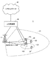
また、図12に示すように複数のスモールセルSとの間のパスロス値や上り干渉量(IoT)を用いた送信電力制御(図ではこれらを用いて仮想的なパスロス値や送信電力の上限値を設定している)を行うことで、周波数利用効率の増大が期待できる。例えば、TP(Transmission Point)#1−TP#4からなるTPグループ内にユーザ端末UEが属する場合を考える。この場合、ユーザ端末UEは、TP#1−#4のパスロス値(PL1−PL4)を推定して、仮想的なパスロス値による第1の送信電力制御、又は送信電力の上限値による第2の送信電力制御が実施される。
Further, as shown in FIG. 12, transmission power control using path loss values and uplink interference amounts (IoT) with a plurality of small cells S (in the figure, these are used to determine virtual path loss values and upper limit values of transmission power. The frequency utilization efficiency can be expected to increase. For example, consider a case where the user terminal UE belongs to a TP group composed of TP (Transmission Point) # 1 to
第1の送信電力制御では、PLを仮想的なパスロス値、ΩをTPグループ、PLiを各スモールセルSのパスロス値とすると、次式(1)により仮想的なパスロス値が算出される。なお、f(PLi∈Ω)は調和平均を求める関数である。

第2の送信電力制御では、P〜 CMAXを仮想的な送信力の上限値(P〜は、Pの上に〜を付したものである)、PCMAXを送信電力の上限値、ΩをTPグループ、PLiを各スモールセルSのパスロス値、IoTMaxを上り干渉量とすると、次式(2)により仮想的な送信電力の上限値が算出される。なお、g(PLi∈Ω,IoTMax)は、所定の干渉レベルの送信電力を求める関数である。
このように、第1、第2の送信電力制御によって、周囲に干渉を与えない程度にユーザ端末UEの送信電力が抑えられるので、ユーザ端末UE間(スモールセルS間)の干渉を減らして、各ユーザ端末UE(スモールセルS)での周波数利用効率が向上される。 Thus, since the transmission power of the user terminal UE is suppressed to such an extent that the first and second transmission power controls do not interfere with the surroundings, the interference between the user terminals UE (between the small cells S) is reduced, The frequency utilization efficiency in each user terminal UE (small cell S) is improved.
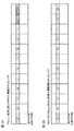
以下、図3及び図4を参照して、上り信号系列のランダム化について説明する。なお、ユーザ端末は、マクロセルをPCellとし、スモールセルをSCell(NCT)としてキャリアアグリゲーションしているものとする。また、図3においては、実際には各サブフレームの前半スロット及び後半スロットに異なる系列番号が割り当てられるが、説明の便宜上、ここでは各スロットに対する割り当てを省略して記載している。 Hereinafter, randomization of the uplink signal sequence will be described with reference to FIGS. It is assumed that the user terminal performs carrier aggregation with the macro cell as the PCell and the small cell as the SCell (NCT). In FIG. 3, different sequence numbers are actually assigned to the first half slot and the second half slot of each subframe. However, for convenience of explanation, the assignment to each slot is omitted here.
まず、上り信号系列の第1のランダム化方法について説明する。図3Aに示すように、PCellでは10msec周期で上り信号系列の系列番号がホッピングされている。すなわち、10サブフレーム周期で、系列番号のホッピングパターンが繰り返されている。例えば、先頭サブフレームから10サブフレーム目までに系列番号[3、10、12、25、4、13、7、29、15、11]が割り当てられ、11サブフレーム目からも同様のホッピングパターンが適用される。 First, the first randomizing method of the uplink signal sequence will be described. As shown in FIG. 3A, the sequence number of the upstream signal sequence is hopped at a period of 10 msec in the PCell. That is, the sequence number hopping pattern is repeated in a period of 10 subframes. For example, a sequence number [3, 10, 12, 25, 4, 13, 7, 29, 15, 11] is assigned from the first subframe to the 10th subframe, and a similar hopping pattern is also assigned from the 11th subframe. Applied.
PCellでは、10サブフレーム周期でホッピングパターンが繰り返されても十分に上り信号系列のランダム化を図ることができる。なお、PCellにおいて10サブフレーム周期でホッピングパターンが繰り返されるのは、最初にPCellとのフレーム同期を確立する必要があるからである。フレーム番号が確立する前なので、サブフレーム番号の関数としてホッピングパターンを定義する必要がある。 In PCell, it is possible to sufficiently randomize an upstream signal sequence even if a hopping pattern is repeated in a period of 10 subframes. Note that the hopping pattern is repeated in the PCell with a period of 10 subframes because it is necessary to first establish frame synchronization with the PCell. Since the frame number has not yet been established, it is necessary to define a hopping pattern as a function of the subframe number.
一方、図3Bに示すように、SCellでは、フレーム同期がPCellで確立済みなので、PCellよりも長周期(10msec以上)で上り信号系列の系列番号をホッピングすることができる。すなわち、10サブフレーム以上の周期で、系列番号のホッピングパターンが繰り返されている。例えば、先頭サブフレームから順に系列番号[3、10、12、25、4、13、7、29、15、11、8、20、…]が割り当てられ、次に周期でも同様のホッピングパターンが適用されている。 On the other hand, as shown in FIG. 3B, in SCell, since frame synchronization has already been established in PCell, the sequence number of the uplink signal sequence can be hopped in a longer cycle (10 msec or more) than PCell. That is, the sequence number hopping pattern is repeated at a period of 10 subframes or more. For example, sequence numbers [3, 10, 12, 25, 4, 13, 7, 29, 15, 11, 8, 20,...] Are assigned in order from the first subframe, and the same hopping pattern is applied in the next cycle. Has been.
SCellでは、このようにPCellよりもホッピングの周期を比較的長くできるため、ホッピングパターンを増加させることができる。よって、上り信号系列のランダム化、すなわち上りのDM−RS、PUCCHのランダム化を十分に図ることができ、スモールセルのセルプランニングを簡易化することが可能になっている。また、上り信号系列の系列数を増やすことなく、ランダム化を図ることができるため、系列数を多くとることができない狭帯域送信の場合にも有効である。なお、SCellでは、サブフレーム番号だけでなく、フレーム番号の関数としてホッピングパターンを定義することも可能である。 In SCell, the hopping cycle can be made relatively longer than in PCell in this way, so that the hopping pattern can be increased. Therefore, randomization of the uplink signal sequence, that is, randomization of the uplink DM-RS and PUCCH can be sufficiently achieved, and the cell planning of the small cell can be simplified. Further, since randomization can be achieved without increasing the number of upstream signal sequences, it is also effective in narrowband transmission where the number of sequences cannot be increased. In SCell, it is possible to define a hopping pattern as a function of not only the subframe number but also the frame number.
なお、第1のランダム化方法において、ホッピングパターンをユーザ端末で決定してもよいし、無線基地局で決定してもよい。ホッピングパターンは、RRCシグナリングで通知されてもよい。また、ホッピングパターンは、セルIDやUSIDに応じて決定されるように規定されているため、USIDに関連付けて通知されてもよい。また、後述する第2のUSIDのみに関連付けて通知されてもよい。なお、USIDの通知方法については後述する。 In the first randomizing method, the hopping pattern may be determined by the user terminal or the radio base station. The hopping pattern may be notified by RRC signaling. Further, since the hopping pattern is defined so as to be determined according to the cell ID or the USID, the hopping pattern may be notified in association with the USID. Further, notification may be made in association with only the second USID described later. The USID notification method will be described later.
次に、上り信号系列の第2のランダム化方法について説明する。上り信号系列は、サブキャリアと同数程度とることができるため、図4Aに示す狭帯域送信の場合には、上り信号系列を多くとることができない。これに対し、図4Bに示す広帯域送信の場合には、サブキャリア数に合わせて上り信号系列を多くとることができる。このため、所定帯域以上の広帯域送信時に、上り信号系列を増加させることでランダム化を図ることも可能である。例えば、5MHzの広帯域であれば300サブキャリアであり、上り信号系列数を約300個まで増やすことができる。 Next, a second randomizing method for uplink signal sequences will be described. Since the number of uplink signal sequences can be as many as the number of subcarriers, a large number of uplink signal sequences cannot be obtained in the case of narrowband transmission shown in FIG. 4A. On the other hand, in the case of wideband transmission shown in FIG. 4B, it is possible to increase the number of uplink signal sequences in accordance with the number of subcarriers. For this reason, it is also possible to achieve randomization by increasing the number of uplink signal sequences during wideband transmission over a predetermined band. For example, if the bandwidth is 5 MHz, the number of subcarriers is 300, and the number of upstream signal sequences can be increased to about 300.
この場合、所定帯域以上(例えば、50リソースブロック以上)の広帯域送信の場合に上り信号系列数を増加するようにする。特にSCellでは、高周波数帯キャリアを用いた広帯域送信がメインとなるため、上り信号系列数を増やすことは有効である。このような構成により、ホッピングパターンを増やすことなく、上り信号系列のランダム化を図ることが可能である。また、広帯域送信時に十分な系列数がとれる場合に、上り信号系列のグループホッピングを無効してもよい。 In this case, the number of uplink signal sequences is increased in the case of wideband transmission of a predetermined band or more (for example, 50 resource blocks or more). In particular, in SCell, wideband transmission using a high frequency band carrier is the main, so increasing the number of uplink signal sequences is effective. With such a configuration, it is possible to randomize the upstream signal sequence without increasing the hopping pattern. Further, group hopping of uplink signal sequences may be invalidated when a sufficient number of sequences can be obtained during wideband transmission.
グループホッピングでは、前半スロットと後半スロットに異なる上り信号系列が割り当てられるが(図4A参照)、第2のランダム化方法を採用してグループホッピングを無効にすると、前半スロットと後半スロットに同じ上り信号系列が割り当てられる(図4B参照)。このように、広帯域送信時にはグループホッピングによる上り信号系列のランダム化の代わりに、上り信号系列の系列数を増加させている。この場合、複数のユーザ間でOCC(Orthogonal Cover Code)による直交化が図られている。 In group hopping, different upstream signal sequences are assigned to the first half slot and the second half slot (see FIG. 4A). However, if group hopping is disabled by adopting the second randomization method, the same upstream signal is assigned to the first half slot and the second half slot. A sequence is assigned (see FIG. 4B). In this way, the number of upstream signal sequences is increased instead of randomization of upstream signal sequences by group hopping during wideband transmission. In this case, orthogonalization by an OCC (Orthogonal Cover Code) is achieved among a plurality of users.
また、図11に示すように、OCCの代わりにSRS(Sounding Reference Signal)で用いられているComb(くしの歯)を用いて直交化を行ってもよい。この場合、くし歯の間でデータを送信しなくてもよいし、くしの歯の隙間でデータを送信してもよい。また、くしの歯に加えてさらに前半スロットと後半スロットに同じ上り信号系列を割り当てるOCCを併用するような例も挙げられる。従って、これらの切り替えを、制御信号を用いてユーザ端末に通知してもよい。 Further, as shown in FIG. 11, orthogonalization may be performed using a comb (comb tooth) used in SRS (Sounding Reference Signal) instead of OCC. In this case, it is not necessary to transmit data between the comb teeth, and data may be transmitted through the gaps between the comb teeth. In addition to the comb teeth, there is an example in which OCC that assigns the same upstream signal sequence to the first half slot and the second half slot is used together. Therefore, the switching may be notified to the user terminal using the control signal.
また、第2のランダム化方法において、上り信号系列の増加及びグループホッピングのオンオフを、ユーザ端末で決定してもよいし、無線基地局で決定してもよい。上り信号系列の増加及びグループホッピングのオンオフの指示は、RRCシグナリングで通知されてもよいし、USIDに関連付けて通知されてもよい。また、後述する第2のUSIDのみに関連付けて通知されてもよい。 Further, in the second randomizing method, the increase of the uplink signal sequence and the on / off of the group hopping may be determined by the user terminal or the radio base station. The instruction to increase the uplink signal sequence and turn on / off the group hopping may be notified by RRC signaling or may be notified in association with the USID. Further, notification may be made in association with only the second USID described later.
また、第1のランダム化方法と第2のランダム化方法を組み合わせてもよい。この場合、所定帯域よりも狭い狭帯域送信の場合に第1のランダム化方法を適用し、所定帯域以上の広帯域送信の場合に第2のランダム化方法を適用するようにする。このような構成により、狭帯域送信時にはホッピングパターンを増やして上り信号系列の衝突確立が下げられ、広帯域送信時には上り信号系列の系列数を増やして上り信号系列の衝突確立が下げられる。よって、SCellの送信帯域に応じて適切なランダム化方法を動的に選択することが可能になっている。 Further, the first randomizing method and the second randomizing method may be combined. In this case, the first randomizing method is applied in the case of narrowband transmission narrower than a predetermined band, and the second randomizing method is applied in the case of wideband transmission of a predetermined band or higher. With such a configuration, the hopping pattern is increased during narrowband transmission to lower the uplink signal sequence collision establishment, and the broadband signal transmission is increased in the number of upstream signal sequence collisions to reduce the uplink signal sequence collision establishment. Therefore, it is possible to dynamically select an appropriate randomizing method according to the SCell transmission band.
第1のランダム化方法及び第2のランダム化方法を動的に変更する場合、いずれのランダム化方法に変更するかを、ユーザ端末で決定してもよいし、無線基地局で決定してもよい。無線基地局でランダム化方法を決定する場合、RRCシグナリングやUSIDによってランダム化方法が通知されてもよい。なお、USIDの通知方法については後述する。 When dynamically changing the first randomizing method and the second randomizing method, the user terminal or the radio base station may determine which randomizing method to change to. Good. When the randomization method is determined by the radio base station, the randomization method may be notified by RRC signaling or USID. The USID notification method will be described later.
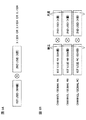
次に図5を参照して、SCell用のUSIDの拡張方法について説明する。SCell用のUSIDは、Rel−11で規定されたUSID(仮想セルID)を拡張して生成される。この場合、既存の504個のUSIDを第1のUSID(第1の識別子)とし、この第1のUSIDに加えて第2のUSID(第2の識別子)を定義することでUSID数を増加させる。図5Aに示すように、第1のUSIDを第2のUSIDによって拡散(乗算)することでUSID数を増加させる。この場合、第2のUSIDの数は、Rel−11で規定されたUSIDと同数の504個でもよいし、504個より多くてもよいし、504個より少なくてもよい。 Next, referring to FIG. 5, a method for extending the USID for SCell will be described. The USID for SCell is generated by extending the USID (virtual cell ID) defined by Rel-11. In this case, the existing 504 USIDs are set as the first USID (first identifier), and the number of USIDs is increased by defining the second USID (second identifier) in addition to the first USID. . As shown in FIG. 5A, the number of USIDs is increased by spreading (multiplying) the first USID by the second USID. In this case, the number of second USIDs may be 504, which is the same as the USID defined by Rel-11, may be more than 504, or may be less than 504.
なお、SCell用のUSIDは、第1のUSIDと第2のUSIDとから算出されればよく、算出方法は特に限定されない。例えば、第1のUSIDと第2のUSIDとを加算するようにしてもよい。また、次式(3)に示すように、SCell用のUSID数は、第2のUSIDが0個の場合にRel−11で規定されたUSID数と一致するようにしてもよい。なお、次式(3)は一例に過ぎず、この構成に限定されない。
(3)
USID=第1のUSID+第2のUSID×第1のUSID数(504)
Note that the SCell USID may be calculated from the first USID and the second USID, and the calculation method is not particularly limited. For example, the first USID and the second USID may be added. Further, as shown in the following equation (3), the number of USIDs for SCell may match the number of USIDs defined by Rel-11 when the second USID is zero. In addition, following Formula (3) is only an example and is not limited to this structure.
(3)
USID = first USID + second USID × first USID number (504)
また、図5Bに示すように、第1のUSIDは各物理チャネル及び信号に独立に適用されるが、第2のUSIDは各物理チャネル及び信号に対して共通又はグループ単位で適用されてもよい。なお、第2のUSIDのグループ単位は、例えば上りリンクと下りリンクでグループ化されてもよい。また、第2の識別子は、第2のUSID等のユーザ固有の識別子に限定されない。第2の識別子は、第1のUSIDとの演算によってUSIDを生成する識別子であればよい。 5B, the first USID is applied independently to each physical channel and signal, but the second USID may be applied to each physical channel and signal in common or in group units. . Note that the group unit of the second USID may be grouped, for example, in uplink and downlink. Further, the second identifier is not limited to a user-specific identifier such as a second USID. The second identifier may be an identifier that generates a USID by calculation with the first USID.
なお、SCell用のUSIDは、PCell(マクロセル)からRRCシグナリングによってユーザ個別に通知されてもよいし、SCell(スモールセル)から報知チャネルやRRCシグナリングによって通知されてもよい。SCellから通知される場合、SCell検出用に規定されたDS(Discovery Signal)の信号系列に関連付けられてもよい。また、SCell用のUSIDが第1のUSIDと第2のUSIDとで生成される場合、第1のUSIDと第2のUSIDとが異なる方法で通知されてもよい。 Note that the SCell USID may be notified individually from the PCell (macro cell) by RRC signaling, or may be notified from the SCell (small cell) by a broadcast channel or RRC signaling. When notified from the SCell, it may be associated with a DS (Discovery Signal) signal sequence defined for SCell detection. Moreover, when the USID for SCell is generated by the first USID and the second USID, the first USID and the second USID may be notified by different methods.
例えば、第1のUSIDはPCellから通知され、第2のUSIDはSCellからDSに関連付けて通知されてもよい。また、第1のUSIDはPCellから通知され、第2のUSIDはSCellから報知されてもよい。さらに、第1のUSIDはPCellからRRCシグナリングで通知され、第2のUSIDはPCellのセルIDに関連付けて通知されてもよい。第2のUSIDの適用の有無は、ユーザ端末に対してNCTや特定のTM(Transmission Mode)を適用するか否かを示すシグナリングに関連付けられてもよい。 For example, the first USID may be notified from the PCell, and the second USID may be notified from the SCell in association with the DS. Moreover, 1st USID may be notified from PCell and 2nd USID may be alert | reported from SCell. Further, the first USID may be notified from the PCell by RRC signaling, and the second USID may be notified in association with the PCell cell ID. Whether or not the second USID is applied may be associated with signaling indicating whether or not NCT or a specific TM (Transmission Mode) is applied to the user terminal.
以下、本実施の形態に係る無線通信システムについて、詳細に説明する。この無線通信システムでは、上記した上り信号系列の第1、第2のランダム化方法が適用される。 Hereinafter, the radio communication system according to the present embodiment will be described in detail. In this radio communication system, the first and second randomization methods for the uplink signal sequence described above are applied.
図6は、本実施の形態に係る無線通信システムの概略構成図である。なお、図6に示す無線通信システムは、例えば、LTEシステム或いは、SUPER 3Gが包含されるシステムである。この無線通信システムでは、LTEシステムのシステム帯域幅を1単位とする複数の基本周波数ブロック(コンポーネントキャリア)を一体としたキャリアアグリゲーション(CA)を適用することができる。また、この無線通信システムは、IMT−Advancedと呼ばれても良いし、4G、FRA(Future Radio Access)と呼ばれても良い。 FIG. 6 is a schematic configuration diagram of the radio communication system according to the present embodiment. Note that the radio communication system shown in FIG. 6 is a system including, for example, an LTE system or SUPER 3G. In this radio communication system, carrier aggregation (CA) in which a plurality of basic frequency blocks (component carriers) having the system bandwidth of the LTE system as one unit can be applied. Further, this radio communication system may be called IMT-Advanced, or may be called 4G, FRA (Future Radio Access).
図6に示す無線通信システム1は、マクロセルC1を形成する無線基地局11と、マクロセルC1内に配置され、マクロセルC1よりも狭いスモールセルC2を形成する無線基地局12a、12bを備えている。また、マクロセルC1及び各スモールセルC2には、ユーザ端末20が配置されている。ユーザ端末20は、無線基地局11及び無線基地局12の双方に接続すること(dual connectivity)ができる。この場合、ユーザ端末20は、異なる周波数を用いるマクロセルC1とスモールセルC2を、CA(Carrier Aggregation)により同時に使用することが想定される。
The
ユーザ端末20と無線基地局11との間は、相対的に低い周波数帯域(例えば、2GHz)で帯域幅が狭いキャリア(Legacy carrier等と呼ばれる)を用いて通信が行なわれる。一方、ユーザ端末20と無線基地局12との間は、相対的に高い周波数帯域(例えば、3.5GHz等)で帯域幅が広いキャリアが用いられてもよいし、無線基地局11との間と同じキャリアが用いられてもよい。ユーザ端末20と無線基地局12間のキャリアタイプとしてニューキャリアタイプ(NCT)を利用してもよい。無線基地局11と無線基地局12(又は、無線基地局12間)は、有線接続(Optical fiber、X2インターフェース等)又は無線接続されている。
Communication between the
無線基地局11及び各無線基地局12は、それぞれ上位局装置30に接続され、上位局装置30を介してコアネットワーク40に接続される。なお、上位局装置30には、例えば、アクセスゲートウェイ装置、無線ネットワークコントローラ(RNC)、モビリティマネジメントエンティティ(MME)等が含まれるが、これに限定されるものではない。また、各無線基地局12は、無線基地局11を介して上位局装置30に接続されてもよい。
The
なお、無線基地局11は、相対的に広いカバレッジを有する無線基地局であり、eNodeB、マクロ基地局、送受信ポイントなどと呼ばれてもよい。また、無線基地局12は、局所的なカバレッジを有する無線基地局であり、スモール基地局、ピコ基地局、フェムト基地局、Home eNodeB、RRH(Remote Radio Head)、マイクロ基地局、送受信ポイントなどと呼ばれてもよい。以下、無線基地局11及び12を区別しない場合は、無線基地局10と総称する。各ユーザ端末20は、LTE、LTE−Aなどの各種通信方式に対応した端末であり、移動通信端末だけでなく固定通信端末を含んでよい。
The
無線通信システムにおいては、無線アクセス方式として、下りリンクについてはOFDMA(直交周波数分割多元接続)が適用され、上りリンクについてはSC−FDMA(シングルキャリア−周波数分割多元接続)が適用される。OFDMAは、周波数帯域を複数の狭い周波数帯域(サブキャリア)に分割し、各サブキャリアにデータをマッピングして通信を行うマルチキャリア伝送方式である。SC−FDMAは、システム帯域幅を端末毎に1つ又は連続したリソースブロックからなる帯域に分割し、複数の端末が互いに異なる帯域を用いることで、端末間の干渉を低減するシングルキャリア伝送方式である。 In a radio communication system, OFDMA (Orthogonal Frequency Division Multiple Access) is applied to the downlink and SC-FDMA (Single Carrier Frequency Division Multiple Access) is applied to the uplink as radio access schemes. OFDMA is a multi-carrier transmission scheme that performs communication by dividing a frequency band into a plurality of narrow frequency bands (subcarriers) and mapping data to each subcarrier. SC-FDMA is a single-carrier transmission scheme that reduces interference between terminals by dividing the system bandwidth into bands composed of one or continuous resource blocks for each terminal, and a plurality of terminals using different bands. is there.
ここで、図6に示す無線通信システムで用いられる通信チャネルについて説明する。下りリンクの通信チャネルは、各ユーザ端末20で共有されるPDSCH(Physical Downlink Shared Channel)と、下りL1/L2制御チャネル(PDCCH、PCFICH、PHICH、拡張PDCCH)とを有する。PDSCHにより、ユーザデータ及び上位制御情報が伝送される。PDCCH(Physical Downlink Control Channel)により、PDSCHおよびPUSCHのスケジューリング情報等が伝送される。PCFICH(Physical Control Format Indicator Channel)により、PDCCHに用いるOFDMシンボル数が伝送される。PHICH(Physical Hybrid-ARQ Indicator Channel)により、PUSCHに対するHARQのACK/NACKが伝送される。また、EPDCCHにより、PDSCH及びPUSCHのスケジューリング情報等が伝送されてもよい。このEPDCCHは、PDSCH(下り共有データチャネル)と周波数分割多重される。
Here, communication channels used in the wireless communication system shown in FIG. 6 will be described. The downlink communication channel includes a PDSCH (Physical Downlink Shared Channel) shared by each
上りリンクの通信チャネルは、各ユーザ端末20で共有される上りデータチャネルとしてのPUSCH(Physical Uplink Shared Channel)と、上りリンクの制御チャネルであるPUCCH(Physical Uplink Control Channel)とを有する。このPUSCHにより、ユーザデータや上位制御情報が伝送される。また、PUCCHにより、下りリンクの無線品質情報(CQI:Channel Quality Indicator)、ACK/NACK等が伝送される。
The uplink communication channel includes a PUSCH (Physical Uplink Shared Channel) as an uplink data channel shared by each
図7は、本実施の形態に係る無線基地局10(無線基地局11及び12を含む)の全体構成図である。無線基地局10は、MIMO伝送のための複数の送受信アンテナ101と、アンプ部102と、送受信部(送信部、受信部)103と、ベースバンド信号処理部104と、呼処理部105と、伝送路インターフェース106とを備えている。
FIG. 7 is an overall configuration diagram of the radio base station 10 (including the
下りリンクにより無線基地局10からユーザ端末20に送信されるユーザデータは、上位局装置30から伝送路インターフェース106を介してベースバンド信号処理部104に入力される。
User data transmitted from the
ベースバンド信号処理部104では、PDCPレイヤの処理、ユーザデータの分割・結合、RLC(Radio Link Control)再送制御の送信処理などのRLCレイヤの送信処理、MAC(Medium Access Control)再送制御、例えば、HARQの送信処理、スケジューリング、伝送フォーマット選択、チャネル符号化、逆高速フーリエ変換(IFFT:Inverse Fast Fourier Transform)処理、プリコーディング処理が行われて各送受信部103に転送される。また、下りリンクの制御チャネルの信号に関しても、チャネル符号化や逆高速フーリエ変換等の送信処理が行われて、各送受信部103に転送される。
The baseband
また、ベースバンド信号処理部104は、報知チャネルにより、ユーザ端末20に対して、当該セルにおける通信のための制御情報を通知する。なお、ユーザ端末が無線基地局11と無線基地局12の双方に接続する場合(dual connection)、中央制御局として機能する無線基地局12からユーザ端末へ報知チャネルを用いて情報を通知することができる。
Moreover, the baseband
各送受信部103は、ベースバンド信号処理部104からアンテナ毎にプリコーディングして出力されたベースバンド信号を無線周波数帯に変換する。アンプ部102は、周波数変換された無線周波数信号を増幅して送受信アンテナ101により送信する。
Each transmission /
一方、上りリンクによりユーザ端末20から無線基地局10に送信されるデータについては、各送受信アンテナ101で受信された無線周波数信号がそれぞれアンプ部102で増幅され、各送受信部103で周波数変換されてベースバンド信号に変換され、ベースバンド信号処理部104に入力される。
On the other hand, for data transmitted from the
ベースバンド信号処理部104では、入力されたベースバンド信号に含まれるユーザデータに対して、FFT処理、IDFT処理、誤り訂正復号、MAC再送制御の受信処理、RLCレイヤ、PDCPレイヤの受信処理がなされ、伝送路インターフェース106を介して上位局装置30に転送される。呼処理部105は、通信チャネルの設定や解放等の呼処理や、無線基地局10の状態管理や、無線リソースの管理を行う。
The baseband
図8は、本実施の形態に係る無線基地局10(無線基地局11及び12を含む)が有するベースバンド信号処理部104の主な機能構成図である。図8に示すように、無線基地局10が有するベースバンド信号処理部104は、スケジューラ111と、データ信号生成部112と、制御信号生成部113と、参照信号生成部114と、上位制御信号生成部115と、を含んで構成されている。なお、上述したように、ベースバンド信号処理部104は、再送制御の送信処理、チャネル符号化、プリコーディング、IFFT処理等を行う機能部も有している。
FIG. 8 is a main functional configuration diagram of baseband
スケジューラ111は、PDSCHで伝送される下りユーザデータ、PDCCH及び/又は拡張PDCCH(EPDCCH)で伝送される下り制御情報、参照信号のスケジューリングを行う。具体的に、スケジューラ111は、上位局装置30からの指示情報や各ユーザ端末20からのフィードバック情報(例えば、CQI、RIなどを含むCSI)に基づいて、無線リソースの割り当てを行う。なお、スケジューラ111が各スモール基地局12のスケジューリングを行う構成とすることもできる。
The
上位制御信号生成部115は、マクロセルC1のセルIDに関する情報、スモールセルC2のUSIDに関する情報、システム帯域幅に関する情報等を生成する。USIDに関する情報には、ユーザ端末20において第1、第2のUSIDからUSIDを生成する場合に第1、第2のUSIDが含まれる。またUSIDに関する情報には、無線基地局10において第1、第2のUSIDからスモールセルC2用のUSIDを生成する場合に、第1、第2のUSIDから生成されたUSIDが含まれる。
The upper control
データ信号生成部112は、スケジューラ111により各サブフレームへの割当てが決定されたユーザ端末20に対するデータ信号(PDSCH信号)を生成する。データ信号生成部112により生成されるデータ信号には、上位制御信号生成部115により生成される上位制御信号が含まれる。
The data signal
制御信号生成部113は、スケジューラ111により各サブフレームへの割当てが決定されたユーザ端末20に対する制御信号(PDCCH信号及び/又はEPDCCH信号)を生成する。また、参照信号生成部114は、下りリンクで送信する各種参照信号を生成する。無線基地局10がスモールセルC2の無線基地局12の場合、参照信号生成部114はスモールセル用の同期信号であるDS(Discovery Signal)を生成する。
The control
なお、本実施の形態では、USIDに関する情報が上位制御信号で通知される構成としているが、この構成に限定されない。USIDに関する情報は、制御チャネル、報知チャネルで通知されてもよい。また、USIDは、マクロセルC1の無線基地局11からユーザ端末20に通知されてもよいし、スモールセルC2の無線基地局12からユーザ端末20に通知されてもよい。無線基地局12からUSIDが通知される場合、スモールセル検出用のDSに関連付けて通知されてもよい。
In addition, in this Embodiment, although it is set as the structure by which the information regarding USID is notified by a high-order control signal, it is not limited to this structure. Information regarding the USID may be notified through a control channel and a broadcast channel. Further, the USID may be notified to the
また、第1、第2のUSIDを異なる方法で通知してもよい。第1のUSIDは、マクロセルC1の無線基地局11からユーザ端末20に通知され、第2のUSIDは、DSに関連付けてスモールセルC2の無線基地局12からユーザ端末20に通知されてもよい。また、第1のUSIDは、マクロセルC1の無線基地局11からユーザ端末20にRRCシグナリングで通知され、第2のUSIDは、マクロセルC1用のセルIDに関連付けて通知されてもよい。また、第2のUSIDの適用は、NCTやTMの適用の有無に関連づけられてもよい。
Further, the first and second USIDs may be notified by different methods. The first USID may be notified to the
図9は、本実施の形態に係るユーザ端末20の全体構成図である。ユーザ端末20は、MIMO伝送のための複数の送受信アンテナ201と、アンプ部202と、送受信部(受信部)203と、ベースバンド信号処理部204と、アプリケーション部205とを備えている。
FIG. 9 is an overall configuration diagram of the
下りリンクのデータについては、複数の送受信アンテナ201で受信された無線周波数信号がそれぞれアンプ部202で増幅され、送受信部203で周波数変換されてベースバンド信号に変換される。このベースバンド信号は、ベースバンド信号処理部204でFFT処理や、誤り訂正復号、再送制御の受信処理等がなされる。この下りリンクのデータの内、下りリンクのユーザデータは、アプリケーション部205に転送される。アプリケーション部205は、物理レイヤやMACレイヤより上位のレイヤに関する処理等を行う。また、下りリンクのデータの内、報知情報もアプリケーション部205に転送される。
For downlink data, radio frequency signals received by a plurality of transmission /
一方、上りリンクのユーザデータについては、アプリケーション部205からベースバンド信号処理部204に入力される。ベースバンド信号処理部204では、再送制御(H−ARQ (Hybrid ARQ))の送信処理や、チャネル符号化、プリコーディング、DFT処理、IFFT処理等が行われて各送受信部203に転送される。送受信部203は、ベースバンド信号処理部204から出力されたベースバンド信号を無線周波数帯に変換する。その後、アンプ部202は、周波数変換された無線周波数信号を増幅して送受信アンテナ201により送信する。送受信部203は、無線基地局から通知されるサブフレーム種別に関する情報等を受信する受信部として機能する。
On the other hand, uplink user data is input from the
図10は、ユーザ端末20が有するベースバンド信号処理部204の主な機能構成図である。図10に示すように、ユーザ端末20が有するベースバンド信号処理部204は、データ信号生成部211、制御信号生成部(信号生成部)212、参照信号生成部(信号生成部)213、上位制御信号取得部214、ホッピングパターン決定部215、マッピング部(信号割当部)216を少なくとも有している。なお、上述したように、ベースバンド信号処理部204は、再送制御の送信処理、チャネル符号化、プリコーディング、DFT処理、IFFT処理等を行う機能部も有している。
FIG. 10 is a main functional configuration diagram of the baseband
データ信号生成部211は、下りの制御信号に基づき無線基地局10に対するデータ信号(PUSCH信号)を生成する。制御信号生成部212は、Zadoff−Chu系列等の上り信号系列に基づき無線基地局10に対するフィードバック情報(PUCCH信号)を生成する。参照信号生成部213は、Zadoff−Chu系列等の上り信号系列に基づき、下りリンクで送信する各種参照信号(DM−RS等)を生成する。なお、制御信号生成部212及び参照信号生成部213は、ホッピングパターン決定部215でグループホッピングが無効にされると、信号系列数の多い(系列長の長い)上り信号系列から信号を生成する。
The data signal
上位制御信号取得部214は、無線基地局10から通知された上位制御信号を取得する。上位制御信号には、マクロセルC1のセルIDに関する情報、スモールセルC2のUSIDに関する情報、システム帯域幅に関する情報等が含まれている。上位制御信号取得部214は、USIDに関する情報として、無線基地局10で生成されたUSIDを取得してもよい。この場合、上位制御信号取得部214は、マクロセルC1の無線基地局11からUSIDを取得してもよいし、スモールセルC2の無線基地局12からUSIDを取得してもよい。
The upper control
また、上位制御信号取得部214は、無線基地局10から第1、第2のUSIDを個々に取得して、ユーザ端末20でUSIDを生成してもよい(図5参照)。この場合、上位制御信号取得部214は、マクロセルC1の無線基地局11から第1のUSIDを取得し、スモールセルC2の無線基地局12から第2のUSIDを取得してもよい。
Further, the upper control
ホッピングパターン決定部215は、上位制御信号取得部214で取得した上位制御信号に基づいてホッピングパターンを決定する。ホッピングパターン決定部215は、マクロセルC1のセルIDに基づいて初期化される疑似ランダム系列によって、マクロセルC1(PCell)用のホッピングパターンを決定する。また、ホッピングパターン決定部215は、スモールセルC2のUSIDに基づいて初期化される疑似ランダム系列によって、スモールセルC(SCell)用のホッピングパターンを決定する。疑似ランダム系列の初期値Cinitは、例えば、式(4)により初期化される。なお、nRS IDは、セルID又はUSIDである。
ホッピングパターン決定部215で決定されるホッピングパターンは、マクロセルC1よりもスモールセルC2が長周期に設定されている(図3参照)。このため、上り信号系列のルート系列数に制限があっても、グループホッピングによって上りのチャネル及び信号のランダム化を図ることが可能になっている。特に、狭帯域送信のように上り信号系列数を増やすことができない場合に有効である。
In the hopping pattern determined by the hopping
また、ホッピングパターン決定部215は、上位制御信号取得部214で取得したシステム帯域幅に基づいてグループホッピングのオンオフを制御することもできる。例えば、スモールセルC2のシステム帯域幅が、所定の帯域幅よりも狭い狭帯域送信時の場合にグループホッピングを有効にし、所定の帯域幅よりも広い広帯域送信時の場合にグループホッピングを無効してもよい。グループホッピングを無効にする場合には、グループホッピングを無効にする代わりに、上り信号系列の系列数を増加させる。広帯域送信の場合にはサブキャリア数と同等まで信号系列数を増やすことでスモールセル間のランダム化を図っている。なお、広帯域送信時にグループホッピングを有効してもよい。これにより、上り信号系列数を増加させると共に、ホッピングパターンによるランダム化を図ることができる。
The hopping
マッピング部216は、データ信号生成部211で生成されたデータ信号、制御信号生成部212で生成された制御信号、参照信号生成部213で生成された参照信号を所定のリソースにマッピングする。この場合、上り信号系列から生成されるDM−RS及びPUCCH信号は、ホッピングパターン決定部215で決定されたホッピングパターンに基づいてマッピングされる。例えば、マクロセル用のDM−RS及びPUCCH信号については、比較的短い10サブフレーム周期のホッピングパターンによってマッピングされる(図3A参照)。また、スモールセル用のDM−RS及びPUCCH信号については、比較的長い長周期のホッピングパターンによってマッピングされる(図3B参照)。また、マッピング部216は、グループホッピングが無効にされた場合、ホッピングパターンを使用せずにマッピングする。
The
このように、ユーザ端末20は、スモールセルC2に対してマクロセルC1よりも長周期のホッピングパターンを用いることにより、スモールセルC2の増加に対応して上り信号系列のランダム化を図ることができる。また、広帯域送信時には、サブキャリア数に合わせて上り信号系列数を増加させて上り信号系列の直交化を図ることができる。よって、マクロセルC1に多数のスモールセルC2が配置される場合に、スモールセルC2のセルプランニングが簡易化される。
As described above, the
なお、本実施の形態では、無線基地局10からユーザ端末20にUSIDを通知することで、ユーザ端末20にホッピングパターンを決定させる構成としているが、この構成に限定されない。無線基地局10でホッピングパターンを決定して、無線基地局10からユーザ端末20にホッピングパターンを通知してもよい。なお、ホッピングパターンの通知は、上位制御信号、制御チャネル、報知チャネルのいずれにて通知してもよい。また、ホッピングパターンは、USID及び第2のUSIDに関連付けて通知されてもよい。
In the present embodiment, the
また、本実施の形態では、無線基地局10からユーザ端末20にシステム帯域幅を通知することで、上り信号系列数の増加やグループホッピングのオンオフを指示する構成としているが、この構成に限定されない。無線基地局10で上り信号系列数やグループホッピングのオンオフを決定して、無線基地局10からユーザ端末20に上り信号系列数やグループホッピングのオンオフを通知してもよい。なお、上り信号系列数やグループホッピングのオンオフの通知は、上位制御信号、制御チャネル、報知チャネルのいずれにて通知してもよい。また、ホッピングパターンは、USID及び第2のUSIDに関連付けて通知されてもよい。
Further, in the present embodiment, the
以上のように、本実施の形態に係る無線通信システム1によれば、スモールセルC2ではマクロセルC1よりも長周期のホッピングパターンを用いて上り信号系列がホッピングされるため、信号系列数を増加させることなく、スモールセルC2間で上り信号系列を十分にランダム化することができる。このため、上り信号系列から生成される上りの制御信号のランダム化を図り、さらにマクロセルC1内に多数のスモールセルC2を組み込む際のセルプランニングを簡易化することができる。
As described above, according to the
本発明は上記実施の形態に限定されず、様々変更して実施することが可能である。例えば、本発明の範囲を逸脱しない限りにおいて、上記説明におけるキャリア数、キャリアの帯域幅、シグナリング方法、処理部の数、処理手順については適宜変更して実施することが可能である。その他、本発明の範囲を逸脱しないで適宜変更して実施することが可能である。 The present invention is not limited to the embodiment described above, and can be implemented with various modifications. For example, the number of carriers, the carrier bandwidth, the signaling method, the number of processing units, and the processing procedure in the above description can be appropriately changed and implemented without departing from the scope of the present invention. Other modifications can be made without departing from the scope of the present invention.
例えば、本実施の形態では、USIDに基づいてスモールセルに対するホッピングパターンが決定される構成としたが、この構成に限定されない。ホッピングパターンは、スモールセルに対してマクロセルよりも長周期のホッピングパターンが決定されれば、どのように決定されてもよい。したがって、本実施の形態に係るランダム化方法は、USIDを適用しない通信システムにおいても適用可能である。 For example, in the present embodiment, the hopping pattern for the small cell is determined based on the USID, but is not limited to this configuration. The hopping pattern may be determined in any way as long as a hopping pattern having a longer period than the macro cell is determined for the small cell. Therefore, the randomizing method according to the present embodiment can also be applied to a communication system that does not apply USID.
また、本実施の形態では、スモールセル用にNCTを適用した通信システムに本発明を適用したが、この構成に限定されない。本発明は、スモールセルに対してマクロセルと同じ周波数キャリアが用いられる場合にも適用可能である。 Moreover, in this Embodiment, although this invention was applied to the communication system which applied NCT for small cells, it is not limited to this structure. The present invention is also applicable to the case where the same frequency carrier as that of the macro cell is used for the small cell.
また、本実施の形態では、上り信号系列により生成されるDM−RS、PUCCH信号を例示して説明したが、この構成に限定されない。本発明は、SRS等の他の参照信号、他の物理チャネル信号にも適用可能である。 In the present embodiment, the DM-RS and the PUCCH signal generated by the uplink signal sequence are exemplified and described, but the present invention is not limited to this configuration. The present invention is also applicable to other reference signals such as SRS and other physical channel signals.
また、本実施の形態では、ホッピングパターン決定部215において、システム帯域幅が所定帯域幅以上か否かを判定する構成としたが、この構成に限定されない。ベースバンド信号処理部204には、システム帯域幅が所定帯域幅以上か否かを判定する判定部が別途設けられていてもよい。
In the present embodiment, the hopping
1 無線通信システム
10、11、12 無線基地局
20 ユーザ端末
103 送受信部(送信部、受信部)
104 ベースバンド信号処理部
111 スケジューラ
112 データ信号生成部
113 制御信号生成部
114 参照信号生成部
115 上位制御信号生成部
203 送受信部
204 ベースバンド信号処理部
211 データ信号生成部
212 制御信号生成部(信号生成部)
213 参照信号生成部(信号生成部)
214 上位制御信号取得部
215 ホッピングパターン決定部
216 マッピング部(信号割当部)
C1 マクロセル
C2 スモールセル
DESCRIPTION OF
104 baseband
213 Reference signal generator (signal generator)
214 Host control
C1 Macrocell C2 Small cell
Claims (10)
同期点以外の自己相関が0になる上り信号系列を用いて上り信号を生成する信号生成部と、
所定周期内のサブフレーム毎に前記上り信号系列の系列番号を切り替えるホッピングパターンを用いて、サブフレームに前記上り信号を割り当てる信号割当部とを備え、
前記マクロ基地局に対するホッピングパターンよりも、前記スモール基地局に対するホッピングパターンにおいて、前記上り信号系列をホッピングさせる周期が長周期であることを特徴とするユーザ端末。 A macro base station that covers a macro cell, and a user terminal that can communicate with a small base station that covers a small cell arranged in the macro cell,
A signal generation unit that generates an uplink signal using an uplink signal sequence in which autocorrelation other than the synchronization point is 0;
A signal allocation unit that allocates the uplink signal to a subframe using a hopping pattern that switches a sequence number of the uplink signal sequence for each subframe within a predetermined period;
The user terminal characterized in that in the hopping pattern for the small base station, the period for hopping the uplink signal sequence is longer than the hopping pattern for the macro base station.
スモールセル用のセル識別子をユーザ端末に送信する送信部と、
同期点以外の自己相関が0になる上り信号系列を用いて生成された上り信号を前記ユーザ端末から受信する受信部とを備え、
前記スモールセル用のセル識別子は、前記上り信号系列の系列番号が所定周期内のサブフレーム毎に切り替わるように、ホッピングパターンを前記ユーザ端末に決定させ、
前記マクロ基地局に対するホッピングパターンよりも、前記スモール基地局に対するホッピングパターンにおいて、前記上り信号系列をホッピングさせる周期が長周期であることを特徴とするスモール基地局。 A small cell is arranged in a macro cell covered by a macro base station, and is a small base station that covers the small cell,
A transmitter that transmits a cell identifier for the small cell to the user terminal;
A receiving unit that receives an uplink signal generated using an uplink signal sequence in which autocorrelation other than the synchronization point is 0, from the user terminal;
The cell identifier for the small cell causes the user terminal to determine a hopping pattern so that the sequence number of the uplink signal sequence is switched for each subframe within a predetermined period,
The small base station, wherein a period of hopping the uplink signal sequence is longer in a hopping pattern for the small base station than in a hopping pattern for the macro base station.
前記スモール基地局が、スモールセル用のセル識別子を前記ユーザ端末に送信し、
前記ユーザ端末が、同期点以外の自己相関が0になる上り信号系列を用いて上り信号を生成し、
前記ユーザ端末が、前記スモールセル用のセル識別子に基づいて所定周期内のサブフレーム毎に前記上り信号系列の系列番号を切り替えるホッピングパターンを決定し、当該ホッピングパターンを用いてサブフレームに前記上り信号を割り当て、
前記マクロ基地局に対するホッピングパターンよりも、前記スモール基地局に対するホッピングパターンにおいて、前記上り信号系列をホッピングさせる周期が長周期であることを特徴とする通信方法。 A macro base station covering a macro cell and a communication method in which a small base station covering a small cell arranged in the macro cell and a user terminal communicate with each other,
The small base station transmits a cell identifier for a small cell to the user terminal,
The user terminal generates an uplink signal using an uplink signal sequence in which autocorrelation other than the synchronization point is 0,
The user terminal determines a hopping pattern for switching the sequence number of the uplink signal sequence for each subframe within a predetermined period based on the cell identifier for the small cell, and uses the hopping pattern to transmit the uplink signal to the subframe. Assign
The communication method characterized in that in the hopping pattern for the small base station, the period for hopping the uplink signal sequence is longer than the hopping pattern for the macro base station.
Priority Applications (5)
| Application Number | Priority Date | Filing Date | Title |
|---|---|---|---|
| JP2013079297A JP6155075B2 (en) | 2013-04-05 | 2013-04-05 | User terminal, small base station, and communication method |
| EP17195425.8A EP3316642A1 (en) | 2013-04-05 | 2014-03-31 | User terminal, small base station and communication method |
| US14/782,434 US20160050657A1 (en) | 2013-04-05 | 2014-03-31 | User terminal, small base station and communication method |
| PCT/JP2014/059483 WO2014163045A1 (en) | 2013-04-05 | 2014-03-31 | User terminal, small base station, and communications method |
| EP14779481.2A EP2983431B1 (en) | 2013-04-05 | 2014-03-31 | User terminal, small base station, and communications method |
Applications Claiming Priority (1)
| Application Number | Priority Date | Filing Date | Title |
|---|---|---|---|
| JP2013079297A JP6155075B2 (en) | 2013-04-05 | 2013-04-05 | User terminal, small base station, and communication method |
Related Child Applications (1)
| Application Number | Title | Priority Date | Filing Date |
|---|---|---|---|
| JP2017110863A Division JP2017147769A (en) | 2017-06-05 | 2017-06-05 | User terminal, wireless communication method, and mobile communication system |
Publications (2)
| Publication Number | Publication Date |
|---|---|
| JP2014204307A true JP2014204307A (en) | 2014-10-27 |
| JP6155075B2 JP6155075B2 (en) | 2017-06-28 |
Family
ID=51658341
Family Applications (1)
| Application Number | Title | Priority Date | Filing Date |
|---|---|---|---|
| JP2013079297A Expired - Fee Related JP6155075B2 (en) | 2013-04-05 | 2013-04-05 | User terminal, small base station, and communication method |
Country Status (4)
| Country | Link |
|---|---|
| US (1) | US20160050657A1 (en) |
| EP (2) | EP3316642A1 (en) |
| JP (1) | JP6155075B2 (en) |
| WO (1) | WO2014163045A1 (en) |
Families Citing this family (3)
| Publication number | Priority date | Publication date | Assignee | Title |
|---|---|---|---|---|
| FR3033464B1 (en) * | 2015-03-03 | 2017-03-31 | Sigfox | METHODS FOR TRANSMITTING DATA BETWEEN A TERMINAL AND A FREQUENCY SYNCHRONIZED ACCESS NETWORK ON AN AMOUNT MESSAGE OF SAID TERMINAL |
| WO2016165127A1 (en) * | 2015-04-17 | 2016-10-20 | Mediatek Singapore Pte. Ltd. | Multiple conectivity in millimeter wave system |
| WO2018042372A1 (en) * | 2016-09-01 | 2018-03-08 | Telefonaktiebolaget Lm Ericsson (Publ) | Methods for signaling or receiving cell identity, network identity, and frequency hopping patterns |
Citations (1)
| Publication number | Priority date | Publication date | Assignee | Title |
|---|---|---|---|---|
| WO2013025054A2 (en) * | 2011-08-16 | 2013-02-21 | 엘지전자 주식회사 | Method and apparatus for transmitting uplink reference signal in wireless communication system |
Family Cites Families (11)
| Publication number | Priority date | Publication date | Assignee | Title |
|---|---|---|---|---|
| JP4067755B2 (en) * | 2000-10-24 | 2008-03-26 | 三菱電機株式会社 | Spread spectrum communication system receiver |
| US7778151B2 (en) * | 2006-10-03 | 2010-08-17 | Texas Instruments Incorporated | Efficient scheduling request channel for wireless networks |
| US8086272B2 (en) * | 2007-08-06 | 2011-12-27 | Mitsubishi Electric Research Laboratories, Inc. | Wireless networks incorporating antenna selection based on received sounding reference signals |
| US8675621B2 (en) * | 2008-07-07 | 2014-03-18 | Zte (Usa) Inc. | Using identification sequences in wireless communication systems |
| JP5232660B2 (en) * | 2008-12-26 | 2013-07-10 | 株式会社エヌ・ティ・ティ・ドコモ | Mobile communication system, radio base station and mobile station |
| CN102792622B (en) * | 2010-03-29 | 2015-12-16 | 松下电器(美国)知识产权公司 | Terminal installation, base station apparatus, pilot sending method and method for propagation path estimation |
| EP3416433B1 (en) * | 2011-07-13 | 2021-07-28 | Sun Patent Trust | Terminal apparatus, base station apparatus, transmission method and reception method |
| US8995385B2 (en) * | 2011-08-05 | 2015-03-31 | Samsung Electronics Co., Ltd. | Apparatus and method for UE-specific demodulation reference signal scrambling |
| EP2742635B1 (en) * | 2011-08-12 | 2017-03-29 | Telefonaktiebolaget LM Ericsson (publ) | Methods and apparatuses for handling reference signals in a cellular network |
| KR101584552B1 (en) * | 2011-09-25 | 2016-01-22 | 엘지전자 주식회사 | User equipment and method for transmitting uplink signal, and base station and method for receiving uplink signal |
| US8811332B2 (en) * | 2012-10-31 | 2014-08-19 | Sharp Laboratories Of America, Inc. | Systems and methods for carrier aggregation |
-
2013
- 2013-04-05 JP JP2013079297A patent/JP6155075B2/en not_active Expired - Fee Related
-
2014
- 2014-03-31 US US14/782,434 patent/US20160050657A1/en not_active Abandoned
- 2014-03-31 WO PCT/JP2014/059483 patent/WO2014163045A1/en active Application Filing
- 2014-03-31 EP EP17195425.8A patent/EP3316642A1/en not_active Withdrawn
- 2014-03-31 EP EP14779481.2A patent/EP2983431B1/en not_active Not-in-force
Patent Citations (2)
| Publication number | Priority date | Publication date | Assignee | Title |
|---|---|---|---|---|
| WO2013025054A2 (en) * | 2011-08-16 | 2013-02-21 | 엘지전자 주식회사 | Method and apparatus for transmitting uplink reference signal in wireless communication system |
| JP2014527354A (en) * | 2011-08-16 | 2014-10-09 | エルジー エレクトロニクス インコーポレイティド | Method and apparatus for transmitting uplink reference signal in wireless communication system |
Also Published As
| Publication number | Publication date |
|---|---|
| EP2983431B1 (en) | 2017-10-11 |
| EP2983431A4 (en) | 2016-11-09 |
| WO2014163045A1 (en) | 2014-10-09 |
| US20160050657A1 (en) | 2016-02-18 |
| JP6155075B2 (en) | 2017-06-28 |
| EP2983431A1 (en) | 2016-02-10 |
| EP3316642A1 (en) | 2018-05-02 |
Similar Documents
| Publication | Publication Date | Title |
|---|---|---|
| JP6095991B2 (en) | Wireless base station, user terminal, and wireless communication method | |
| JP5771177B2 (en) | Wireless base station, user terminal, wireless communication system, and wireless communication method | |
| CN108965190B (en) | User terminal | |
| JP6091816B2 (en) | Wireless communication system, base station apparatus, mobile terminal apparatus, and interference measurement method | |
| US9742534B2 (en) | Radio communication method, radio communication system, radio base station and user terminal | |
| EP2836008B1 (en) | Communication system, mobile communication terminal, local area base station device and communication method | |
| EP3425978B1 (en) | User terminal, wireless base station and wireless communication method | |
| WO2014069163A1 (en) | Wireless communication method, wireless communication system, wireless base station, and user terminal | |
| JP6698519B2 (en) | Wireless base station, user terminal, and wireless communication method | |
| JP6164859B2 (en) | Wireless base station, user terminal, and wireless communication method | |
| JP2013211749A (en) | Wireless communication method, wireless base stations, user terminal and wireless communication system | |
| JP6212188B2 (en) | Wireless communication method, wireless base station, and user terminal | |
| JP2015146549A (en) | User terminal, radio base station and radio communication method | |
| WO2014061475A1 (en) | Radio communication method, radio communication system, radio base station and user terminal | |
| JP6320683B2 (en) | Wireless base station, user terminal, and wireless communication method | |
| JP5984769B2 (en) | User terminal, radio base station, and radio communication method | |
| JP7201675B2 (en) | Terminal, wireless communication method and system | |
| JP6155075B2 (en) | User terminal, small base station, and communication method | |
| JPWO2017150447A1 (en) | User terminal, radio base station, and radio communication method | |
| JP2014143606A (en) | Radio communication system, radio communication method, radio base station, and user equipment | |
| JP2017147769A (en) | User terminal, wireless communication method, and mobile communication system | |
| JP2018191335A (en) | User terminal | |
| JP2017143584A (en) | Communication system, base station device, mobile terminal device, and communication method |
Legal Events
| Date | Code | Title | Description |
|---|---|---|---|
| A621 | Written request for application examination |
Free format text: JAPANESE INTERMEDIATE CODE: A621 Effective date: 20160404 |
|
| TRDD | Decision of grant or rejection written | ||
| A01 | Written decision to grant a patent or to grant a registration (utility model) |
Free format text: JAPANESE INTERMEDIATE CODE: A01 Effective date: 20170404 |
|
| A601 | Written request for extension of time |
Free format text: JAPANESE INTERMEDIATE CODE: A601 Effective date: 20170501 |
|
| A61 | First payment of annual fees (during grant procedure) |
Free format text: JAPANESE INTERMEDIATE CODE: A61 Effective date: 20170605 |
|
| R150 | Certificate of patent or registration of utility model |
Ref document number: 6155075 Country of ref document: JP Free format text: JAPANESE INTERMEDIATE CODE: R150 |
|
| LAPS | Cancellation because of no payment of annual fees |