JP2014200618A - Game machine - Google Patents
Game machine Download PDFInfo
- Publication number
- JP2014200618A JP2014200618A JP2013081903A JP2013081903A JP2014200618A JP 2014200618 A JP2014200618 A JP 2014200618A JP 2013081903 A JP2013081903 A JP 2013081903A JP 2013081903 A JP2013081903 A JP 2013081903A JP 2014200618 A JP2014200618 A JP 2014200618A
- Authority
- JP
- Japan
- Prior art keywords
- lamp unit
- unit
- front door
- light
- player
- Prior art date
- Legal status (The legal status is an assumption and is not a legal conclusion. Google has not performed a legal analysis and makes no representation as to the accuracy of the status listed.)
- Granted
Links
Images


Landscapes
- Slot Machines And Peripheral Devices (AREA)
Abstract
Description
本発明は、フロントドアに設けられたランプユニットを有する遊技機に関する。 The present invention relates to a gaming machine having a lamp unit provided on a front door.
近年では、遊技の進行と共に様々な演出を行う遊技機が知られている。例えば、特許文献1に開示されている遊技機では、フロントドアに照明ユニットを設けて光による演出を行っている。この特許文献1に開示された遊技機では、照明ユニットから遊技機の前方に対して光を照射し、遊技者の視覚に訴えかけることで、演出効果をさらに高めている。 In recent years, gaming machines that perform various effects as the game progresses are known. For example, in the gaming machine disclosed in Patent Document 1, a lighting unit is provided on the front door to produce an effect using light. In the gaming machine disclosed in Patent Document 1, the lighting effect is further enhanced by irradiating light from the lighting unit to the front of the gaming machine and appealing to the player's vision.
しかしながら、特許文献1に記載された遊技機は、ランプユニットである照明ユニットがフロントドアに固定されているため、ランプユニットを用いた演出のバリエーションは、光の色の違いや点灯及び点滅の仕方の違いだけであった。そのため、従来の遊技機では、ランプユニットを用いた演出の変化が乏しく、単調なものとなっていた。 However, in the gaming machine described in Patent Document 1, since the lighting unit, which is a lamp unit, is fixed to the front door, there are variations in performance using the lamp unit, such as the difference in the color of light and the way of lighting and blinking. The only difference was. For this reason, conventional gaming machines are monotonous with little change in production using lamp units.
本発明の目的は、上記従来技術における実情を考慮し、ランプユニットを用いて多種多様な演出を行うことができる遊技機を提供することにある。 An object of the present invention is to provide a gaming machine capable of performing a wide variety of effects using a lamp unit in consideration of the actual situation in the prior art.
上記課題を解決し、本発明の目的を達成するため、本発明の遊技機は、キャビネットと、キャビネットに対して開閉可能に取り付けられ、遊技者側の前面が開口した収納部を有するフロントドアと、収納部に設けられ、光を出射するランプユニットと、ランプユニットをフロントドアの前後方向の移動させる可動機構と、を備えている。そして、ランプユニットは、フロントドアの前後方向の前方に向けて光を出射する前面発光部と、ランプユニットにおけるフロントドアの前後方向と直交する側面部から光を出射する側面発光部と、を有している。また、ランプユニットは、可動機構により、収納部の開口から突出し、及び収納部に収納される。そして、側面発光部は、ランプユニットが収納部に収納された際に収納部内に隠れる。 In order to solve the above-described problems and achieve the object of the present invention, a gaming machine of the present invention includes a cabinet, a front door that is attached to the cabinet so as to be openable and closable, and has a storage portion that opens on the front side on the player side. And a lamp unit that emits light, and a movable mechanism that moves the lamp unit in the front-rear direction of the front door. The lamp unit includes a front light-emitting unit that emits light toward the front in the front-rear direction of the front door, and a side light-emitting unit that emits light from a side surface orthogonal to the front-rear direction of the front door in the lamp unit. doing. The lamp unit protrudes from the opening of the storage unit and is stored in the storage unit by the movable mechanism. The side light emitting unit is hidden in the storage unit when the lamp unit is stored in the storage unit.
上記構成の遊技機によれば、光の色の違いや点灯及び点滅の仕方の違いだけでなく、ランプユニットが収納部に収納された状態と、ランプユニットが収納部から突出した状態という演出のバリエーションを増やすことができる。 According to the gaming machine having the above configuration, not only the difference in the color of light and the way of lighting and blinking, but also the effect that the lamp unit is stored in the storage unit and the state where the lamp unit protrudes from the storage unit. Variations can be increased.
上記構成の遊技機によれば、前面発光部からフロントドアの前方に向けて光を出射することで、ランプユニットが収納部に収納されている状態でも遊技者に向けて光を用いた演出を行うことができる。さらに、側面発光部からランプユニットの側面部から光を出射することで、パチスロの前方に位置する遊技者が光で包まれているような感覚を演出することができる。 According to the gaming machine having the above-described configuration, the light is emitted from the front light emitting unit toward the front of the front door, so that an effect using the light is directed toward the player even when the lamp unit is stored in the storage unit. It can be carried out. Furthermore, by emitting light from the side light emitting portion from the side surface portion of the lamp unit, it is possible to produce a feeling that the player located in front of the pachislot is wrapped in light.
また、本発明の遊技機としては、フロントドアに設けられ、表示部を用いて映像による演出を行う表示装置と、を備え、ランプユニットは、フロントドアにおける表示装置の左右方向の両側に配置されるようにしてもよい。 In addition, the gaming machine of the present invention includes a display device that is provided on the front door and that produces an effect using an image using a display unit, and the lamp units are disposed on both sides of the display device on the front door in the left-right direction. You may make it do.
上記構成の遊技機によれば、ランプユニットが収納部の開口からフロントドアの前方に突出した際に、パチスロの前方に位置する遊技者をフロントドアに設けた表示装置と、表示装置の左右の両側に配置されたランプユニットで取り囲むようにすることができる。これにより、ランプユニットから出射される光と、表示装置から出射される光とで遊技者を包み込むようにすることができ、遊技者のパチスロの演出に対する没入感を高めることができる。 According to the gaming machine configured as described above, when the lamp unit protrudes from the opening of the storage portion to the front of the front door, the display device in which the player located in front of the pachislot is provided on the front door, and the left and right of the display device The lamp unit can be surrounded by lamp units arranged on both sides. Thereby, the player can be wrapped with the light emitted from the lamp unit and the light emitted from the display device, and the player's feeling of immersion in the pachislot effect can be enhanced.
また、本発明の遊技機としては、ランプユニットは、略直方体状の本体部と、本体部における上下方向の上部と下部に設けられる略円柱状の2つの円柱部と、を有し、前面発光部は、円柱部における軸方向の遊技者側の端部に設けられ、側面発光部は、本体部における側面部のうち表示装置側の内側面部に設けられるようにしてもよい。 Further, as the gaming machine of the present invention, the lamp unit has a substantially rectangular parallelepiped main body part, and two substantially cylindrical column parts provided at an upper part and a lower part in the vertical direction of the main body part, and emits front light. The portion may be provided at an end portion on the player side in the axial direction of the cylindrical portion, and the side light emitting portion may be provided on the inner side surface portion on the display device side of the side surface portion in the main body portion.
上記構成の遊技機によれば、ランプユニットが収納部に収納された状態では、円柱部の端部に設けられた前面発光部によって略点状に光が出射され、ランプユニットが突出した状態では、本体部に設けられた側面発光部により略面状に光が出射される。これにより、ランプユニットが収納部に収納された状態と、ランプユニットが収納部から突出した状態とで、異なる光の演出を行うことができる。 According to the gaming machine having the above configuration, when the lamp unit is housed in the housing portion, light is emitted in a substantially dot shape by the front light emitting portion provided at the end of the cylindrical portion, and in a state where the lamp unit protrudes. The light is emitted in a substantially planar shape by the side light emitting part provided in the main body part. Thereby, it is possible to produce different light effects in the state where the lamp unit is housed in the housing portion and the state where the lamp unit protrudes from the housing portion.
また、本発明の遊技機としては、ランプユニットに設けられ、遊技者に向けて風を送る送風機構を備えるようにしてもよい。 Further, the gaming machine of the present invention may be provided with a blower mechanism that is provided in the lamp unit and sends wind toward the player.
上記構成の遊技機によれば、送風機構によって遊技者に風を吹き付けるという演出を追加することができる。また、フロントドアに映像を表示する液晶表示装置を設けた際に、液晶表示装置の映像に合わせて送風機構を駆動させることで、映像のスピード感を演出することもできる。 According to the gaming machine having the above configuration, it is possible to add an effect of blowing wind to the player by the blower mechanism. Further, when a liquid crystal display device that displays an image is provided on the front door, it is possible to produce a sense of speed of the image by driving the blower mechanism in accordance with the image of the liquid crystal display device.
本発明の遊技機によれば、ランプユニットを用いて多種多様な演出を行うことができる。 According to the gaming machine of the present invention, a wide variety of effects can be performed using the lamp unit.
本発明の一実施形態を示す遊技機であるパチスロについて、図1〜図9を参照しながら説明する。はじめに、図1を参照して、遊技機の実施の形態に係る機能フローについて説明する。 A pachislot machine that is a gaming machine according to an embodiment of the present invention will be described with reference to FIGS. First, a functional flow according to the embodiment of the gaming machine will be described with reference to FIG.
本実施の形態のパチスロでは、遊技を行うための遊技媒体としてメダルを用いる。なお、遊技媒体としては、メダル以外にも、コイン、遊技球、遊技用のポイントデータ又はトークン等を適用することもできる。 In the pachislot of this embodiment, medals are used as game media for playing games. In addition to the medals, coins, game balls, game point data, tokens, or the like can be applied as game media.
遊技者によりメダルが投入され、スタートレバーが操作されると、予め定められた数値の範囲(例えば、0〜65535)の乱数から1つの値(以下、乱数値)が抽出される。 When a player inserts a medal and operates the start lever, one value (hereinafter, random number value) is extracted from random numbers in a predetermined numerical range (for example, 0 to 65535).
内部抽籤手段は、抽出された乱数値に基づいて抽籤を行い、内部当籤役を決定する。この内部抽籤手段は、後述する主制御回路が担う。内部当籤役の決定により、後述の入賞判定ラインに沿って表示を行うことを許可する図柄の組合せが決定される。なお、図柄の組合せの種別としては、メダルの払い出し、再遊技の作動、ボーナスの作動等といった特典が遊技者に与えられる「入賞」に係るものと、それ以外のいわゆる「ハズレ」に係るものとが設けられている。 The internal lottery means performs lottery based on the extracted random number value and determines an internal winning combination. This internal lottery means is carried out by a main control circuit described later. By determining the internal winning combination, a combination of symbols that permits display along a winning determination line described later is determined. The types of symbol combinations include those related to “winning” in which merits such as paying out medals, re-games, bonuses, etc. are given to players, and other so-called “loses”. Is provided.
また、スタートレバーが操作されると、複数のリールの回転が行われる。その後、遊技者により所定のリールに対応するストップボタンが押されると、リール停止制御手段は、内部当籤役とストップボタンが押されたタイミングとに基づいて、該当するリールの回転を停止する制御を行う。このリール停止制御手段は、後述する主制御回路が担う。 Further, when the start lever is operated, a plurality of reels are rotated. Thereafter, when the player presses the stop button corresponding to the predetermined reel, the reel stop control means performs control to stop the rotation of the corresponding reel based on the internal winning combination and the timing when the stop button is pressed. Do. The reel stop control means is responsible for a main control circuit described later.
パチスロでは、基本的に、ストップボタンが押されたときから規定時間(190msec又は75msec)内に、該当するリールの回転を停止する制御が行われる。本実施形態では、この規定時間内にリールの回転に伴って移動する図柄の数を「滑り駒数」と呼ぶ。規定時間が190msecである場合には、滑り駒数の最大数を図柄4コマ分に定め、規定時間が75msecである場合には、滑り駒数の最大数を図柄1コマ分に定める。 In the pachislot, basically, a control for stopping the rotation of the corresponding reel is performed within a specified time (190 msec or 75 msec) from when the stop button is pressed. In the present embodiment, the number of symbols that move with the rotation of the reel within the specified time is referred to as “the number of sliding symbols”. When the specified time is 190 msec, the maximum number of sliding symbols is set to 4 symbols, and when the specified time is 75 msec, the maximum number of sliding symbols is set to 1 symbol.
リール停止制御手段は、入賞に係る図柄の組合せ表示を許可する内部当籤役が決定されているときは、通常、190msec(図柄4コマ分)の規定時間内に、その図柄の組合せが入賞判定ラインに沿って極力表示されるようにリールの回転を停止させる。また、リール停止制御手段は、例えば、第2種特別役物であるチャレンジボーナス(CB)及びCBを連続して作動させるミドルボーナス(MB)の動作時には、1つ以上のリールに対して、規定時間75msec(図柄1コマ分)内に、その図柄の組合せが入賞判定ラインに沿って極力表示されるようにリールの回転を停止させる。さらに、リール停止制御手段は、遊技状態に対応する各種規定時間を利用して、内部当籤役によってその表示が許可されていない図柄の組合せが入賞判定ラインに沿って表示されないようにリールの回転を停止させる。 When the internal winning combination allowing the symbol combination display related to winning is determined, the reel stop control means usually displays the symbol combination within the specified time of 190 msec (four symbols) for the winning determination line. The rotation of the reel is stopped so as to display as much as possible. In addition, the reel stop control means is defined for one or more reels when, for example, a challenge bonus (CB), which is a second-type special accessory, and a middle bonus (MB) for continuously operating the CB are operated. The reel rotation is stopped so that the combination of symbols is displayed as much as possible along the winning determination line within a time of 75 msec (for one symbol). Furthermore, the reel stop control means uses various specified times corresponding to the gaming state to rotate the reels so that combinations of symbols that are not permitted to be displayed by the internal winning combination are not displayed along the winning determination line. Stop.
こうして、複数のリールの回転がすべて停止されると、入賞判定手段は、入賞判定ラインに沿って表示された図柄の組合せが、入賞に係るものであるか否かの判定を行う。この入賞判定手段は、後述する主制御回路が担う。入賞判定手段により入賞に係るものであるとの判定が行われると、メダルの払い出し等の特典が遊技者に与えられる。パチスロでは、以上のような一連の流れが1回の遊技として行われる。 Thus, when the rotation of the plurality of reels is all stopped, the winning determination means determines whether or not the combination of symbols displayed along the winning determination line is related to winning. This winning determination means is carried out by a main control circuit described later. When it is determined by the winning determination means that it is related to winning, a privilege such as paying out medals is given to the player. In the pachislot, a series of flows as described above is performed as one game.
また、パチスロでは、前述した一連の流れの中で、液晶表示装置などの表示装置により行う映像の表示、各種ランプにより行う光の出力、スピーカにより行う音の出力、或いはこれらの組合せを利用して様々な演出が行われる。 Further, in the pachislot, in the above-described series of flows, video display performed by a display device such as a liquid crystal display device, light output performed by various lamps, sound output performed by a speaker, or a combination thereof is used. Various productions are performed.
スタートレバーが操作されると、上述した内部当籤役の決定に用いられた乱数値とは別に、演出用の乱数値(以下、演出用乱数値)が抽出される。演出用乱数値が抽出されると、演出内容決定手段は、内部当籤役に対応づけられた複数種類の演出内容の中から今回実行するものを抽籤により決定する。この演出内容決定手段は、後述する副制御回路が担う。 When the start lever is operated, an effect random number value (hereinafter referred to as effect random number value) is extracted separately from the random number value used for determining the internal winning combination. When the effect random number value is extracted, the effect content determining means determines, by lottery, what is to be executed this time from among a plurality of types of effect contents associated with the internal winning combination. This effect content determination means is carried out by a sub-control circuit described later.
演出内容が決定されると、演出実行手段は、リールの回転開始時、各リールの回転停止時、入賞の有無の判定時等の各契機に連動させて対応する演出を実行する。このように、パチスロでは、内部当籤役に対応づけられた演出内容を実行することによって、決定された内部当籤役(言い換えると、狙うべき図柄の組合せ)を知る機会又は予想する機会が遊技者に提供され、遊技者の興味の向上を図ることができる。 When the contents of the effect are determined, the effect executing means executes the corresponding effect in conjunction with each opportunity, such as when the rotation of the reels starts, when the rotation of each reel stops, or when determining whether there is a winning. In this way, in the pachislot machine, the player has the opportunity to know or predict the determined internal winning combination (in other words, the combination of symbols to be aimed at) by executing the production contents associated with the internal winning combination. It is possible to improve the player's interest.
<パチスロの構造>
次に、図2〜図6を参照して、本実施形態におけるパチスロの構造について説明する。なお、図2は、本実施形態のパチスロ1の外部構造を示す斜視図である。
<Pachislot structure>
Next, the structure of the pachislot machine according to the present embodiment will be described with reference to FIGS. FIG. 2 is a perspective view showing an external structure of the pachislot machine 1 of the present embodiment.
[外観構造]
パチスロ1は、図2に示すように、リールや回路基板等を収容したキャビネット1aと、キャビネット1aに対して開閉可能に取り付けられたフロントドア1bとを備える。キャビネット1aの内部には、3つのリール3L,3C,3R(変動表示手段)が設けられ、該3つのリール3L,3C,3Rは横方向(リールの回転方向と直交する方向)に一列に配置される。以下、リール3L,3C,3Rを、それぞれ左リール3L、中リール3C、右リール3Rという。
[Appearance structure]
As shown in FIG. 2, the pachi-slot 1 includes a
各リール(表示列)は、円筒状のリール本体と、リール本体の周面(周回面)に装着された透光性のシート材とを有する。シート材の表面には、複数(例えば21個)の図柄がリール本体の周方向に沿って連続的に描かれる。 Each reel (display row) has a cylindrical reel body and a translucent sheet material mounted on the peripheral surface (circumferential surface) of the reel body. A plurality of (for example, 21) symbols are continuously drawn on the surface of the sheet material along the circumferential direction of the reel body.
フロントドア1bの中央には、液晶表示装置10と、3つのリール3L,3C,3Rに描かれた図柄を表示する表示窓4とが設けられる。そして、液晶表示装置10は、映像の表示が行われ、演出が実行される。
At the center of the
表示窓4は、例えばアクリル板等の透明部材で構成され、図2に示すように、正面(遊技者側)から見て、3つのリールの配置領域と重畳する位置に設けられ、かつ、3つのリールより手前(遊技者側)に位置するように設けられる。それゆえ、表示窓4の背後に設けられた3つのリールに描かれた図柄が、表示窓4を介して目視することができる。 The display window 4 is made of, for example, a transparent member such as an acrylic plate, and is provided at a position overlapping with the three reel arrangement areas when viewed from the front (player side) as shown in FIG. It is provided so as to be positioned in front of one reel (player side). Therefore, the symbols drawn on the three reels provided behind the display window 4 can be viewed through the display window 4.
また、正面から見て表示窓4の左側方には、7セグメントLED(Light Emitting Diode)からなる7セグ表示器6が設けられる。7セグ表示器6は、今回の遊技に投入されたメダルの枚数(以下、投入枚数という)、特典として遊技者に払い出されるメダルの枚数(以下、払出枚数という)、パチスロ1の内部に預けられているメダルの枚数(以下、クレジット枚数という)等の情報をデジタル表示する。
In addition, a 7-
また、フロントドア1bには、遊技者の操作対象となる各種装置(メダル投入口11、MAXベットボタン12、1BETボタン14、スタートレバー16、ストップボタン17L,17C,17R)が設けられる。
Further, the
メダル投入口11は、遊技者によって外部からパチスロ1に投入されるメダルを受け入れるために設けられる。メダル投入口11を介して受け入れられたメダルは、所定枚数(例えば3枚)を上限として1回の遊技に投入され、所定枚数を超えた分は、パチスロ1の内部に預けることができる(いわゆるクレジット機能)。なお、本実施形態のパチスロ1では、後述のように、1回の遊技に投入可能なメダルの枚数は、1枚、2枚及び3枚のいずれかである。
The
MAXベットボタン12及び1BETボタン14は、パチスロ1の内部に預けられているメダルから1回の遊技に投入する枚数を決定するために設けられる。なお、図2には示さないが、フロントドア1bには、精算ボタンが設けられる(スタートレバー16のストップボタン側とは反対側の側部に配置されている)。この精算ボタンは、パチスロ1の内部に預けられているメダルを外部に引き出す(排出する)ために設けられる。
The
スタートレバー16は、全てのリール(3L,3C,3R)の回転を開始するために設けられる。ストップボタン17L,17C,17Rは、それぞれ、左リール3L、中リール3C、右リール3Rに対応づけて設けられ、各ストップボタンは対応するリールの回転を停止するために設けられる。以下、ストップボタン17L,17C,17Rを、それぞれ左ストップボタン17L、中ストップボタン17C、右ストップボタン17Rという。
The
さらに、フロントドア1bには、メダル払出口18、メダル受皿19、スピーカ20L,20R、ランプユニット21及び送風機構22(図6参照)等が設けられる。
Further, the
メダル払出口18は、後述のメダル払出装置33の駆動により排出されるメダルを外部に導く。メダル受皿19は、メダル払出口18から排出されたメダルを貯める。また、スピーカ20L,20Rは、演出内容に対応する効果音や楽曲等の音を出力する。
The
なお、本実施形態では、液晶表示装置10を備える構成を説明するが、本発明はこれに限定されない。例えば、リールの上部に複数のLEDをマトリックス状に配置し、これらのLEDの点消灯によるドットパターンにより、演出(報知)を行う構成にしてもよい。
In addition, although this embodiment demonstrates the structure provided with the liquid
また、フロントドア1bにおける液晶表示装置10の左右の両端に位置する二つの側辺部には、それぞれ収納部101が設けられている。収納部101は、前面が開口した凹部である。この収納部101には、ランプユニット21が設けられている。ランプユニット21は、LED等で構成され、演出内容に対応するパターンで、光を点灯及び消灯する。このランプユニット21は、可動機構121(図8参照)によってフロントドア1bの前後方向に移動(図2及び図7参照)する。そして、ランプユニット21は、演出内容に応じて収納部101の開口から突出し、または収納部101内に収納される。
In addition, a
さらに、ランプユニット21には、送風機構22(図6参照)が設けられている。送風機構22は、演出内容に応じて遊技者側に風を送る。これにより、液晶表示装置10に例えば疾走感のある映像が映し出された際に、送風機構22から遊技者側に風を送ることで、映像のスピード感を高めることができる。
Further, the
[内部構造]
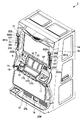
次に、パチスロ1の内部構造を、図3及び図4を参照しながら説明する。なお、図3は、フロントドア1bが開放され、フロントドア1bの裏面側に設けたミドルドア25がフロントドア1bに対して閉じた状態を示す図である。また、図4では、フロントドア1bが開放され、ミドルドア25がフロントドア1bに対して開いた状態を示している。
[Internal structure]
Next, the internal structure of the pachislot machine 1 will be described with reference to FIGS. FIG. 3 is a diagram illustrating a state in which the
キャビネット1aの内部の下側には、キャビネット1a内の下方部分には、多量のメダルを収容可能であり、かつ、それらを1枚ずつ排出可能な構造を有するメダル払出装置33(以下、ホッパー33という)が設けられる。また、キャビネット1a内における、ホッパー33の一方の側部(図3に示す例では左側)には、パチスロ1が有する各装置に対して必要な電力を供給する電源装置34が設けられる。
Below the interior of the
図3及び図4に示すように、ミドルドア25は、フロントドア1bの裏面における中央部に配置され、表示窓4(図4参照)を裏側から開閉可能に構成されている。ミドルドア25の上部と下部には、ドアストッパ25a,25b,25cが設けられている。このドアストッパ25a,25b,25cは、表示窓4を裏側から閉じた状態のミドルドア25の開動作を固定(禁止)する。すなわち、ミドルドア25を開くには、ドアストッパ25a,25b,25cを回転させてミドルドア25の固定を解除する必要がある。
As shown in FIGS. 3 and 4, the
ミドルドア25には、後述の主制御回路41(図5参照)を構成する主基板31が設けられる。主制御回路41は、内部当籤役の決定、各リールの回転及び停止、入賞の有無の判定等の、パチスロ1における遊技の主な動作及び該動作間の流れを制御する回路である。なお、主制御回路41の具体的な構成は後述する。
The
また、ミドルドア25の中央部分には、3つのリール(左リール3L、中リール3C及び右リール3R)が設けられる。なお、図3には示さないが、各リールは、所定の減速比を有するギアを介して対応する後述のステッピングモータ(図5中のステッピングモータ61L,61C,61Rのいずれか)に接続される。
Further, three reels (a
ミドルドア25の上方には、後述の副制御回路42(図5及び図6参照)を構成する副基板32が設けられる。副制御回路42は、映像の表示等による演出の実行を制御する回路である。なお、副制御回路42の具体的な構成は後述する。
Above the
さらに、フロントドア1bの裏側部において、表示窓4の配置領域の下方部分には、セレクタ35が設けられる。セレクタ35は、メダル投入口11を介して外部から投入されたメダルの材質や形状等が適正である否かを選別する装置であり、適正であると判定されたメダルをホッパー33に案内する。また、図3には示さないが、セレクタ35内においてメダルが通過する経路上には、適正なメダルが通過したことを検出するメダルセンサ35S(後述の図5参照)が設けられる。
Further, a
<パチスロが備える回路の構成>
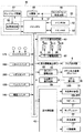
次に、図5及び図6を参照して、本実施形態におけるパチスロ1が備える回路の構成について説明する。なお、図5は、パチスロ1が備える回路全体のブロック構成図であり、図6は、副制御回路の内部構成を示すブロック構成図である。
<Configuration of circuits provided in pachislot>
Next, with reference to FIG. 5 and FIG. 6, a configuration of a circuit included in the pachi-slot 1 in the present embodiment will be described. FIG. 5 is a block configuration diagram of the entire circuit included in the pachi-slot 1, and FIG. 6 is a block configuration diagram illustrating an internal configuration of the sub control circuit.
パチスロ1は、図5に示すように、主制御回路41、副制御回路42、及び、これらの回路と電気的に接続される周辺装置(アクチュエータ)を備える。
As shown in FIG. 5, the pachi-slot 1 includes a
[主制御回路]
主制御回路41は、主に、回路基板(主基板31)上に設置されたマイクロコンピュータ50により構成される。それ以外の構成要素として、主制御回路41は、図7に示すように、クロックパルス発生回路54、分周器55、乱数発生器56、サンプリング回路57、表示部駆動回路64、ホッパー駆動回路65、及び、払出完了信号回路66を含む。
[Main control circuit]
The
マイクロコンピュータ50は、メインCPU51(特別遊技制御手段、通常遊技制御手段)、メインROM(Read Only Memory)52及びメインRAM(Random Access Memory)53により構成される。
The
メインROM52には、メインCPU51により実行される各種処理の制御プログラム、内部抽籤テーブル等のデータテーブル、副制御回路42に対して各種制御指令(コマンド)を送信するためのデータ等が記憶される。メインRAM53には、制御プログラムの実行により決定された内部当籤役等の各種データを格納する格納領域が設けられる。
The
メインCPU51には、図5に示すように、クロックパルス発生回路54、分周器55、乱数発生器56及びサンプリング回路57が接続される。クロックパルス発生回路54及び分周器55は、クロックパルスを発生する。なお、メインCPU51は、発生されたクロックパルスに基づいて、制御プログラムを実行する。また、乱数発生器56は、予め定められた範囲の乱数(例えば、0〜65535)を発生する。そして、サンプリング回路57は、発生された乱数の中から1つの値を抽出する。
As shown in FIG. 5, a clock
マイクロコンピュータ50の入力ポートには、各種スイッチ及びセンサ等が接続される。メインCPU51は、各種スイッチ等からの入力信号を受けて、ステッピングモータ61L,61C,61R等の周辺装置の動作を制御する。
Various switches and sensors are connected to the input port of the
ストップスイッチ17S(停止操作検出手段)は、左ストップボタン17L、中ストップボタン17C、右ストップボタン17Rのそれぞれが遊技者により押されたこと(停止操作)を検出する。スタートスイッチ16S(開始操作検出手段)は、スタートレバー16が遊技者により操作されたこと(開始操作)を検出する。精算スイッチ14Sは、精算ボタンが遊技者により押されたことを検出する。
The stop switch 17S (stop operation detecting means) detects that the player has pressed each of the
メダルセンサ35S(投入操作検出手段)は、メダル投入口11に投入されたメダルがセレクタ35内を通過したことを検出する。また、ベットスイッチ12Sは、ベットボタン(MAXベットボタン12又は1BETボタン14)が遊技者により押されたことを検出する。
The medal sensor 35S (insertion operation detecting means) detects that a medal inserted into the
また、マイクロコンピュータ50により動作が制御される周辺装置としては、3つのステッピングモータ61L,61C,61R(変動表示手段)、7セグ表示器6及びホッパー33がある。また、マイクロコンピュータ50の出力ポートには、各周辺装置の動作を制御するための駆動回路が接続される。
Peripheral devices whose operations are controlled by the
モータ駆動回路62は、左リール3L、中リール3C、右リール3Rに対応してそれぞれ設けられた3つのステッピングモータ61L,61C,61Rの駆動を制御する。リール位置検出回路63は、発光部と受光部とを有する光センサにより、リールが一回転したことを示すリールインデックスをリール毎に検出する。
The
3つのステッピングモータ61L,61C,61Rのそれぞれは、その運動量がパルスの出力数に比例し、回転軸を指定された角度で停止させることが可能な構成を有する。また、各ステッピングモータの駆動力は、所定の減速比を有するギアを介して、対応するリールに伝達される。そして、各ステッピングモータに対して1回のパルスが出力されるごとに、対応するリールは一定の角度で回転する。 Each of the three stepping motors 61L, 61C, 61R has a configuration in which the momentum is proportional to the number of output pulses, and the rotation axis can be stopped at a specified angle. The driving force of each stepping motor is transmitted to the corresponding reel via a gear having a predetermined reduction ratio. Each time one pulse is output to each stepping motor, the corresponding reel rotates at a constant angle.
メインCPU51は、各リールのリールインデックスを検出してから対応するステッピングモータに対してパルスが出力された回数をカウントすることによって、各リールの回転角度(具体的には、リールが図柄何個分だけ回転したか)を管理する。
The
ここで、各リールの回転角度の管理を具体的に説明する。各ステッピングモータに対して出力されたパルスの数は、メインRAM53に設けられたパルスカウンタ(不図示)によって計数される。そして、図柄1個分の回転に必要な所定回数(例えば16回)のパルスの出力がパルスカウンタで計数されるごとに、メインRAM53に設けられた図柄カウンタ(不図示)の値に、「1」が加算される。なお、図柄カウンタは、リール毎に設けられる。そして、図柄カウンタの値は、リール位置検出回路63によってリールインデックスが検出されるとクリアされる。
Here, the management of the rotation angle of each reel will be specifically described. The number of pulses output to each stepping motor is counted by a pulse counter (not shown) provided in the
すなわち、本実施形態では、図柄カウンタの値を管理することにより、リールインデックスが検出されてから図柄何個分の回転動作が行われたのかを管理する。それゆえ、各リールの各図柄の位置は、リールインデックスが検出される位置を基準として検出される。 In other words, in the present embodiment, by managing the value of the symbol counter, it is managed how many symbols have been rotated since the reel index was detected. Therefore, the position of each symbol on each reel is detected with reference to the position where the reel index is detected.
本実施形態では、上述のように、通常遊技中の滑り駒数の最大数を図柄4個分に定め、それゆえ、例えば、通常遊技中に所定のリールに対応するストップボタンが押されたときには、表示窓4内の有効ライン上の対応する領域に位置する所定のリールの図柄と、その4個先までの範囲に存在する図柄が、該領域に停止可能な図柄となる。 In this embodiment, as described above, the maximum number of sliding symbols in the normal game is set to 4 symbols, and therefore, for example, when the stop button corresponding to a predetermined reel is pressed during the normal game. The symbols of a predetermined reel located in the corresponding area on the active line in the display window 4 and the symbols existing in the range up to four ahead of them are symbols that can be stopped in the area.
なお、主制御回路41に含まれる、表示部駆動回路64は、7セグ表示器6の動作を制御する。ホッパー駆動回路65は、ホッパー33の動作を制御する。また、払出完了信号回路66は、ホッパー33に設けられたメダル検出部33Sが行うメダルの検出を管理し、ホッパー33から外部に排出されたメダルが所定の払出枚数に達したか否かをチェックする。
A display unit drive circuit 64 included in the
[副制御回路]
副制御回路42は、図5及び図6に示すように、主制御回路41と電気的に接続され、主制御回路41から送信されるコマンドに基づいて演出内容の決定や実行等の処理を行う。副制御回路42は、基本的には、図6に示すように、サブCPU81、サブROM82、サブRAM83、レンダリングプロセッサ84、描画用RAM85、ドライバ86、DSP(Digital Signal Processor)90、オーディオRAM91、A/D(Analog to Digital)変換器92、アンプ93及び可動機構駆動回路96を含む。
[Sub control circuit]
As shown in FIGS. 5 and 6, the
サブCPU81は、主制御回路41から送信されたコマンドに応じて、サブROM82に記憶されている制御プログラムに従い、映像、音、光の出力制御を行う。なお、サブROM82は、基本的には、プログラム記憶領域及びデータ記憶領域を有する。また、サブROM82には、各種のデータテーブルが記憶されている。
The
プログラム記憶領域には、サブCPU81が実行する各種制御プログラムが記憶される。なお、プログラム記憶領域に格納される制御プログラムには、例えば、主制御回路41との通信を制御するための主基板通信タスク、演出用乱数値を抽出して演出内容(演出データ)の決定及び登録を行うための演出登録タスク、決定した演出内容に基づいて液晶表示装置10による映像の表示を制御するための描画制御タスク、ランプユニット21による光の出力を制御するためのランプ制御タスク、スピーカ20L,20Rによる音の出力を制御するための音声制御タスク等のプログラムが含まれる。
Various control programs executed by the
データ記憶領域には、例えば、各種データテーブルを記憶する記憶領域、各種演出内容を構成する演出データを記憶する記憶領域、映像の作成に関するアニメーションデータを記憶する記憶領域、BGMや効果音に関するサウンドデータを記憶する記憶領域、光の点消灯のパターンに関するランプデータを記憶する記憶領域等の各種記憶領域が含まれる。 In the data storage area, for example, a storage area for storing various data tables, a storage area for storing effect data constituting various effects, a storage area for storing animation data relating to creation of video, and sound data relating to BGM and sound effects And various storage areas such as a storage area for storing lamp data relating to a light on / off pattern.
サブRAM83は、決定された演出内容や演出データを登録する格納領域や、主制御回路41から送信される内部当籤役等の各種データを格納する格納領域などを有する。
The
また、副制御回路42には、液晶表示装置10、スピーカ20L,20R、ランプユニット21、送風機構22、可動機構121等の周辺装置が接続され、これらの周辺装置の動作は、副制御回路42により制御される。
Further, peripheral devices such as the liquid
本実施形態では、サブCPU81、レンダリングプロセッサ84、描画用RAM85(フレームバッファを含む)及びドライバ86は、演出内容により指定されたアニメーションデータに従って映像を作成し、該作成した映像は液晶表示装置10により表示される。
In the present embodiment, the
また、サブCPU81、DSP90、オーディオRAM91、A/D変換器92及びアンプ93は、演出内容により指定されたサウンドデータに従ってBGM等の音をスピーカ20L,20Rにより出力する。さらに、サブCPU81は、演出内容により指定されたランプデータに従ってランプユニット21の点灯及び消灯を行う。また、サブCPU81は、演出内容に指定された送風データに従って送風機構22の駆動を行う。
Further, the
さらに、サブCPU81及び可動機構駆動回路96は、所定の演出を行う際に、演出内容により指定された可動機構駆動データに従って、可動機構121の駆動を行う。その結果、ランプユニット21がフロントドア1b(図7参照)から遊技者側に向けて突出し、またはランプユニット21が収納部101(図2参照)に収納される。
Further, the
<ランプユニットの構成>
次に、フロントドア1bに設けられたランプユニット21の構成について、図2及び図7を参照して説明する。
図7は、フロントドア1bからランプユニット21が突出した状態を示す斜視図である。
<Configuration of lamp unit>
Next, the structure of the
FIG. 7 is a perspective view showing a state in which the
図2に示すように、ランプユニット21は、通常状態では、フロントドア1bに設けられた収納部101に収納されている。また、図7に示すように、特定の演出時には、ランプユニット21は、後述する可動機構121(図8及び図9参照)によってフロントドア1bの収納部101から遊技者側に向けて突出する。
As shown in FIG. 2, the
ランプユニット21は、略直方体状の本体部201と、2つの略円柱状の円柱部202、202とを有している。本体部201は、側面発光部201aと、前面発光部201bとを有している。側面発光部201a及び前面発光部201bには、それぞれ光を出射する光源を有している。
The
側面発光部201aは、本体部201におけるフロントドア1bの前後方向と直交する側面部のうち液晶表示装置10側の内側面部に取り付けられている。側面発光部201aは、本体部201の内側面部から、液晶表示装置10側に向けて略面状に光を出射する。これにより、ランプユニット21がフロントドア1bの前方に突出した際に、側面発光部201aから出射される光によって、パチスロ1の前方に位置する遊技者が光で包まれているような感覚を演出することができる。
The side
なお、図2に示すように、ランプユニット21が収納部101内に収納されている状態では、側面発光部201aは、収納部101内に位置する。そのため、側面発光部201aは、収納部101内に隠れて、遊技者側からは側面発光部201aを視認不可能となる。そして、図7に示すように、ランプユニット21が収納部101から突出した際に、側面発光部201aは、収納部101から露出する。
As shown in FIG. 2, in a state where the
また、前面発光部201bは、本体部201における遊技者側の前面部に取り付けられている。そして、前面発光部201bは、本体部201の前面部からパチスロ1の前方に光を出射する。これにより、ランプユニット21が収納部101に収納されている状態でも、パチスロ1の前方に位置する遊技者に対して光を照射することができる。
Further, the front light emitting unit 201b is attached to the front side of the
また、本体部201における上下方向の上部と下部には、それぞれ円柱部202が設けられている。円柱部202は、回転発光部202aと、前面発光部202bとを有している。回転発光部202aは、不図示の光源と、光源の周囲を回転する不図示の反射鏡とを有している。反射鏡は、円柱部202の周方向に沿って回転する。そして、光源から出射した光が回転する反射鏡に反射されると、円柱部202の側周部から周方向に沿って光が出射される向きが順次変更される。これにより、パチスロ1で遊技している遊技者に対する演出効果を高めることができる。
In addition,
なお、図2に示すように、ランプユニット21が収納部101内に収納されている状態では、回転発光部202aは、収納部101内に位置する。そのため、回転発光部202aは、収納部101内に隠れて、遊技者側からは回転発光部202aを視認不可能となる。そして、図7に示すように、ランプユニット21が収納部101から突出した際に、回転発光部202aは、収納部101から露出する。
As shown in FIG. 2, in a state where the
また、前面発光部202bは、円柱部202における遊技者側である軸方向の一端部に設けられている。すなわち、円柱部202は、側周部だけでなく軸方向の一端部から遊技者に向けて光を出射することができる。これにより、ランプユニット21が収納部101に収納されている状態でも、パチスロ1の前方に位置する遊技者に対して光を照射することができる。
Further, the front
さらに、ランプユニット21が収納部101に収納された状態では、円柱部202の前面発光部202bから略点状に光が出射される。そして、ランプユニット21が収納部101から突出した状態では、本体部201の側面発光部201aが露出し、この側面発光部201aから略面状に光が出射される。さらに、円柱部202の回転発光部202aが露出し、円柱部202の側周部か出射方向の向きを順次変更した状態で光が出射される。これにより、本実施形態のランプユニット21によれば、収納部101に収納された状態と収納部101から突出した状態とで、異なる光の演出を行うことができる。
Further, in a state where the
また、本体部201及び円柱部202における液晶表示装置10と反対側の外側面部は、鈍く光るように例えば表面が凹凸状に加工されている。これにより、ランプユニット21がフロントドア1bの前方に突出した際に、パチスロ1の隣に位置する他の遊技者がまぶしくならないようにすることができる。なお、本体部201及び円柱部202における外側面部からも光が出射されるように加工してもよい。これにより、パチスロ1の前方に位置する遊技者だけでなく、パチスロ1の周囲にいる者の興味を引き付けることができる。
Further, for example, the surface of the
<収納部及び可動機構の構成>
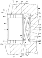
次に、ランプユニット21を収納する収納部101及びランプユニット21を移動させる可動機構121の構成について図8及び図9を参照して説明する。
図8は、フロントドア1bにおける収納部101を示す縦断面図である。図9は、収納部101からランプユニット21が突出した状態を示すフロントドア1bの縦断面図である。
<Configuration of storage unit and movable mechanism>
Next, the configuration of the
FIG. 8 is a longitudinal sectional view showing the
図8に示すように、収納部101は、略長方形の凹部であり、上面を形成する上面部101aと、底面を形成する底面部101bと、開口と対向する背面部101cとを有している。上面部101aと底面部101bには、それぞれ背面部101cから開口にかけて延在するガイドレール211、211が取り付けられている。ガイドレール211には、ランプユニット21の円柱部202に設けたスライダ212、212が摺動可能に支持されている。スライダ212は、ガイドレール211に沿って前後方向にのみ摺動可能となっており、水平方向への移動が規制されている。そのため、ランプユニット21は、スライダ212を介してガイドレール211に沿って収納部101の前後方向にのみ移動する。
As shown in FIG. 8, the
また、ランプユニット21における背面部101cと対向する一面には、保持部材213が設けられている。保持部材213の後方には、可動機構121が設けられている。
A holding
可動機構121は、X型のリンク機構302と、このX型のリンク機構302を駆動させる駆動部303を備えている。リンク機構302は、第1のリンク片305と、第2のリンク片306と、これら2つのリンク片305,306を中間部で回転可能に連結する連結軸307と、2つの摺動支持部材308,309と、2つの送りナット311,312から構成されている。
The
2つの摺動支持部材308,309は、それぞれ保持部材213に摺動可能に係合されている。これら摺動支持部材308,309は、上下方向にのみ摺動可能となっており、水平方向への移動が禁止されている。2つの送りナット311,312は、それぞれ収納部101の背面部101cに摺動可能に係合されている。これら送りナット311,312は、上下方向にのみ摺動可能となっており、水平方向への移動が禁止されている。
The two sliding
第1のリンク片305の一端305a(下端)は、上述した摺動支持部材309に回動可能に支持され、他端305b(上端)は、上述した送りナット311に回動可能に支持されている。また、第2のリンク片306の一端306a(上端)は、上述した摺動支持部材308に回動可能に支持され、他端306b(下端)は、上述した送りナット312に回動可能に支持されている。
One
駆動部303は、駆動モータ321と、この駆動モータ321の回転軸として設けられた送りねじ軸314から構成されている。この駆動モータ321は、可動機構駆動回路96(図6参照)からの駆動信号に基づいて駆動する。
The
送りねじ軸314は、収納部101の上面部101aと底面部101bが対向する方向に延在されている。この送りねじ軸314は、駆動モータ側である半分から下側に設けられたねじ山と、先端側である半分から上側に設けられたねじ山が互いに逆方向に延在されるように構成されている。この送りねじ軸314の上側に設けられたねじ山には、上述した送りナット311が螺合され、下側のねじ山には、上述した送りナット312が螺合されている。
The
駆動モータ321によって送りねじ軸314を一方に回転させると、送りナット311,312は、互いに接近するように上下方向へ移動する。また、送りねじ軸314を他方に回転させると、送りナット311,312は、互いに離反するように上下方向に移動する。これにより、第1のリンク片305及び第2のリンク片306が開閉するように回転し、ランプユニット21が収納部101の前後方向に移動される。
When the
例えば、図8に示す状態から図9に示すように、ランプユニット21を収納部101の開口からフロントドア1bの前方に突出させるには、駆動モータ321によって送りねじ軸314を一方に回転させる。これにより、送りナット311,312が互いに接近するように上下方向へ移動し、第1のリンク片305及び第2のリンク片306が開くように回転する。第1のリンク片305及び第2のリンク片306が開くように回転すると、摺動支持部材308,309が互いに接近するように上下方向へ移動すると共に、第1のリンク片305及び第2のリンク片306が摺動支持部材308,309を介してランプユニット21を収納部101の前側に押圧する。その結果、ランプユニット21がガイドレール211に沿って収納部101の開口から突出する。
For example, as shown in FIG. 9 from the state shown in FIG. 8, in order to project the
このとき、図7に示すように、パチスロ1の前方に位置する遊技者は、フロントドア1bの前面に設けた液晶表示装置10と、2つのランプユニット21,21に取り囲まれたようになる。そして、ランプユニット21、21の本体部201の側面発光部201a及び円柱部202の回転発光部202aから出射される光と、液晶表示装置10から出射される光とで遊技者を包みこむようにすることができる。その結果、遊技者のパチスロ1の演出に対する没入感を高めることができる。
At this time, as shown in FIG. 7, the player located in front of the pachislot 1 is surrounded by the liquid
さらに、ランプユニット21が遊技者に向けて突出した状態で、送風機構22(図6参照)を駆動させて遊技者に向けて風を送ることで、液晶表示装置10に映し出された映像のスピード感を高めることができ、演出の臨場感を向上させることもできる。
Further, in a state where the
また、図9に示す状態から図8に示すように、ランプユニット21を収納部101内に収納させるには、駆動モータ321によって送りねじ軸314を他方に回転させる。これにより、送りナット311,312が互いに離反するように上下方向へ移動し、第1のリンク片305及び第2のリンク片306が閉じるように回転する。第1のリンク片305及び第2のリンク片306が閉じるように回転すると、摺動支持部材308,309が互いに離反するように上下方向へ移動する。そして、第1のリンク片305及び第2のリンク片306が摺動支持部材308,309を介してランプユニット21を収納部101の背面部101c側へ引っ張る。その結果、ランプユニット21がガイドレール211に沿って収納部101内に収納される。
Further, as shown in FIG. 8 from the state shown in FIG. 9, in order to store the
なお、本実施形態では、ランプユニット21を移動させる可動機構121がX型のリンク機構302と、このX型のリンク機構302を駆動させる駆動部303によって構成される例を説明したがこれに限定されるものではない。可動機構121としては、例えばソレノイドを用いた機構や、リニアモータを用いた機構等その他各種の機構を用いてもよい。
In this embodiment, an example in which the
また、本実施形態のパチスロ1によれば、ランプユニット21を用いた演出として、ランプユニット21が収納部101に収納された状態と、ランプユニット21が収納部101から突出した状態というバリエーションを増やすことができる。さらに、送風機構22を用いて遊技者に風を吹き付けるという演出を追加している。これにより、光の色の違いや点灯及び点滅の仕方の違いだけでなく、ランプユニット21を用いて多種多様な演出を行うことができる。
Further, according to the pachi-slot 1 of the present embodiment, as an effect using the
さらに、本実施形態では、ランプユニット21をフロントドア1bにおける液晶表示装置10の左右の両側方に設けた例を説明したが、これに限定されるものではない。例えばランプユニット21をフロントドア1bにおける液晶表示装置10の上方に配置してもよい。これにより、ランプユニット21がフロントドア1bの前面から前方に突出した際に、パチスロ1の前方に位置する遊技者に対して上方から光を照射することができる。
Further, in the present embodiment, the example in which the
以上、本発明の一実施形態に係る遊技機について、その作用効果も含めて説明したが、本発明はここで説明した実施の形態に限定されるものではない。特許請求の範囲に記載した本発明の要旨を逸脱しない限り、種々の実施の形態を含むことは言うまでもない。 As mentioned above, although the game machine concerning one embodiment of the present invention was explained including the operation effect, the present invention is not limited to the embodiment described here. It goes without saying that various embodiments are included without departing from the gist of the present invention described in the claims.
また、上述した実施の形態例では、遊技機としてパチスロ機を用いた例を説明したが、これに限定されるものではなく、例えば、パチンコ機等、その他各種の遊技機であってもよい。 In the embodiment described above, an example using a pachislot machine as a gaming machine has been described. However, the present invention is not limited to this, and various other gaming machines such as a pachinko machine may be used.
1…パチスロ(遊技機)、 2…外装体、 2a…キャビネット、 2b…フロントドア、 3L…左リール、 3C…中リール、 3R…右リール、 4…表示窓、 6…7セグ表示器、 7…把手、 9…ドア本体、 10…液晶表示装置、 11…メダル投入口、 18…メダル払出口、 19…メダル受皿、 20L,20R…スピーカ、 21…ランプユニット、 31…主基板、 32…副基板、 33…ホッパー(メダル払出装置)、 34…電源装置、 35…セレクタ、 41…主制御回路、 42…副制御回路、 101…収納部、 101a…上面部、 101b…底面部、 101c…背面部、 121…可動機構、 201…本体部、 201a…側面発光部、 201b,202b…前面発光部、 202…円柱部、 202a…回転発光部、 211…ガイドレール、 212…スライダ、 213…保持部材、 302…リンク機構、 303…駆動部、 305…第1のリンク片、 306…第2のリンク片、 307…連結軸、 308,309…摺動支持部材、 311,312…送りナット、 314…送りねじ軸、 321…駆動モータ
DESCRIPTION OF SYMBOLS 1 ... Pachislot (game machine), 2 ... Exterior body, 2a ... Cabinet, 2b ... Front door, 3L ... Left reel, 3C ... Middle reel, 3R ... Right reel, 4 ... Display window, 6 ... 7 segment display, 7 DESCRIPTION OF SYMBOLS ... Handle, 9 ... Door main body, 10 ... Liquid crystal display device, 11 ... Medal insertion slot, 18 ... Medal payout opening, 19 ... Medal tray, 20L, 20R ... Speaker, 21 ... Lamp unit, 31 ... Main board, 32 ... Sub Substrate, 33 ... Hopper (medal paying device), 34 ... Power supply device, 35 ... Selector, 41 ... Main control circuit, 42 ... Sub-control circuit, 101 ... Storage part, 101a ... Top surface part, 101b ... Bottom surface part, 101c ... Back surface , 121 ... movable mechanism, 201 ... main body, 201a ... side light emitting part, 201b and 202b ... front light emitting part, 202 ... cylindrical part, 202a ... rotation
Claims (4)
前記キャビネットに対して開閉可能に取り付けられ、遊技者側の前面が開口した収納部を有するフロントドアと、
前記収納部に設けられ、光を出射するランプユニットと、
前記ランプユニットを前記フロントドアの前後方向の移動させる可動機構と、を備え、
前記ランプユニットは、
前記フロントドアの前後方向の前方に向けて光を出射する前面発光部と、
前記ランプユニットにおける前記フロントドアの前後方向と直交する側面部から光を出射する側面発光部と、を有し、
前記可動機構により、前記収納部の開口から突出し、及び前記収納部に収納され、
前記側面発光部は、前記ランプユニットが前記収納部に収納された際に前記収納部内に隠れる
遊技機。 Cabinet,
A front door having a storage portion attached to the cabinet so as to be openable and closable and having an open front on the player side;
A lamp unit that is provided in the housing and emits light;
A movable mechanism for moving the lamp unit in the front-rear direction of the front door,
The lamp unit is
A front light-emitting portion that emits light toward the front in the front-rear direction of the front door;
A side light emitting unit that emits light from a side surface perpendicular to the front-rear direction of the front door in the lamp unit;
The movable mechanism protrudes from the opening of the storage unit, and is stored in the storage unit,
The side light emitting unit is hidden in the storage unit when the lamp unit is stored in the storage unit.
前記ランプユニットは、前記フロントドアにおける前記表示装置の左右方向の両側に配置される
請求項1に記載の遊技機。 A display device provided on the front door and performing an effect by an image using a display unit;
The gaming machine according to claim 1, wherein the lamp units are disposed on both sides of the display device in the left-right direction of the front door.
前記本体部における上下方向の上部と下部に設けられる略円柱状の2つの円柱部と、を有し、
前記前面発光部は、前記円柱部における軸方向の前記遊技者側の端部に設けられ、
前記側面発光部は、前記本体部における側面部のうち前記表示装置側の内側面部に設けられる
請求項2に記載の遊技機。 The lamp unit includes a substantially rectangular parallelepiped main body,
Two substantially cylindrical columnar portions provided at the upper and lower parts in the vertical direction of the main body,
The front light-emitting portion is provided at an end portion on the player side in the axial direction of the cylindrical portion,
The gaming machine according to claim 2, wherein the side light emitting portion is provided on an inner side surface portion on the display device side of the side surface portion in the main body portion.
請求項1〜3のいずれかに記載の遊技機。 The gaming machine according to any one of claims 1 to 3, further comprising a blower mechanism that is provided in the lamp unit and sends wind toward the player.
Priority Applications (1)
| Application Number | Priority Date | Filing Date | Title |
|---|---|---|---|
| JP2013081903A JP6165488B2 (en) | 2013-04-10 | 2013-04-10 | Game machine |
Applications Claiming Priority (1)
| Application Number | Priority Date | Filing Date | Title |
|---|---|---|---|
| JP2013081903A JP6165488B2 (en) | 2013-04-10 | 2013-04-10 | Game machine |
Related Child Applications (1)
| Application Number | Title | Priority Date | Filing Date |
|---|---|---|---|
| JP2017121035A Division JP2017192759A (en) | 2017-06-21 | 2017-06-21 | Game machine |
Publications (2)
| Publication Number | Publication Date |
|---|---|
| JP2014200618A true JP2014200618A (en) | 2014-10-27 |
| JP6165488B2 JP6165488B2 (en) | 2017-07-19 |
Family
ID=52351603
Family Applications (1)
| Application Number | Title | Priority Date | Filing Date |
|---|---|---|---|
| JP2013081903A Expired - Fee Related JP6165488B2 (en) | 2013-04-10 | 2013-04-10 | Game machine |
Country Status (1)
| Country | Link |
|---|---|
| JP (1) | JP6165488B2 (en) |
Cited By (2)
| Publication number | Priority date | Publication date | Assignee | Title |
|---|---|---|---|---|
| JP2015077190A (en) * | 2013-10-15 | 2015-04-23 | 株式会社三共 | Game machine |
| JP2016135317A (en) * | 2016-04-26 | 2016-07-28 | 株式会社三共 | Game machine |
Citations (7)
| Publication number | Priority date | Publication date | Assignee | Title |
|---|---|---|---|---|
| JPH1147382A (en) * | 1997-07-30 | 1999-02-23 | Daiichi Shokai Co Ltd | Display device for pachinko machine |
| JP2001025575A (en) * | 1999-07-14 | 2001-01-30 | Yua Kaihatsu:Kk | Game equipment and game auxiliary machine |
| JP2008161293A (en) * | 2006-12-27 | 2008-07-17 | Daito Giken:Kk | Game machine |
| JP2009112711A (en) * | 2007-11-09 | 2009-05-28 | Sammy Corp | Game machine |
| JP2010046314A (en) * | 2008-08-22 | 2010-03-04 | Universal Entertainment Corp | Game machine |
| JP2010227400A (en) * | 2009-03-27 | 2010-10-14 | Olympia:Kk | Pinball game machine |
| JP2011078630A (en) * | 2009-10-08 | 2011-04-21 | Sophia Co Ltd | Game machine |
-
2013
- 2013-04-10 JP JP2013081903A patent/JP6165488B2/en not_active Expired - Fee Related
Patent Citations (7)
| Publication number | Priority date | Publication date | Assignee | Title |
|---|---|---|---|---|
| JPH1147382A (en) * | 1997-07-30 | 1999-02-23 | Daiichi Shokai Co Ltd | Display device for pachinko machine |
| JP2001025575A (en) * | 1999-07-14 | 2001-01-30 | Yua Kaihatsu:Kk | Game equipment and game auxiliary machine |
| JP2008161293A (en) * | 2006-12-27 | 2008-07-17 | Daito Giken:Kk | Game machine |
| JP2009112711A (en) * | 2007-11-09 | 2009-05-28 | Sammy Corp | Game machine |
| JP2010046314A (en) * | 2008-08-22 | 2010-03-04 | Universal Entertainment Corp | Game machine |
| JP2010227400A (en) * | 2009-03-27 | 2010-10-14 | Olympia:Kk | Pinball game machine |
| JP2011078630A (en) * | 2009-10-08 | 2011-04-21 | Sophia Co Ltd | Game machine |
Cited By (2)
| Publication number | Priority date | Publication date | Assignee | Title |
|---|---|---|---|---|
| JP2015077190A (en) * | 2013-10-15 | 2015-04-23 | 株式会社三共 | Game machine |
| JP2016135317A (en) * | 2016-04-26 | 2016-07-28 | 株式会社三共 | Game machine |
Also Published As
| Publication number | Publication date |
|---|---|
| JP6165488B2 (en) | 2017-07-19 |
Similar Documents
| Publication | Publication Date | Title |
|---|---|---|
| JP2017060714A (en) | Game machine | |
| JP5808452B2 (en) | Game machine | |
| JP2014042693A (en) | Game machine | |
| JP6165488B2 (en) | Game machine | |
| JP2017192759A (en) | Game machine | |
| JP6285999B2 (en) | Game machine | |
| JP5810200B2 (en) | Game machine | |
| JP6199249B2 (en) | Game machine | |
| JP5792872B2 (en) | Game machine | |
| JP5792873B2 (en) | Game machine | |
| JP2017202364A (en) | Game machine | |
| JP6511176B2 (en) | Gaming machine | |
| JP5659201B2 (en) | Game machine | |
| JP6486531B2 (en) | Game machine | |
| JP2017018782A (en) | Game machine | |
| JP6639534B2 (en) | Gaming machine | |
| JP6511173B2 (en) | Gaming machine | |
| JP6133948B2 (en) | Game machine | |
| JP6313151B2 (en) | Game machine | |
| JP6629552B2 (en) | Gaming machine | |
| JP5976181B2 (en) | Game machine | |
| JP6317205B2 (en) | Game machine | |
| JP5961735B2 (en) | Game machine | |
| JP5823001B2 (en) | Game machine | |
| JP2016022028A (en) | Game machine |
Legal Events
| Date | Code | Title | Description |
|---|---|---|---|
| A621 | Written request for application examination |
Free format text: JAPANESE INTERMEDIATE CODE: A621 Effective date: 20151203 |
|
| A977 | Report on retrieval |
Free format text: JAPANESE INTERMEDIATE CODE: A971007 Effective date: 20161014 |
|
| A131 | Notification of reasons for refusal |
Free format text: JAPANESE INTERMEDIATE CODE: A131 Effective date: 20161018 |
|
| A521 | Request for written amendment filed |
Free format text: JAPANESE INTERMEDIATE CODE: A523 Effective date: 20161209 |
|
| TRDD | Decision of grant or rejection written | ||
| A01 | Written decision to grant a patent or to grant a registration (utility model) |
Free format text: JAPANESE INTERMEDIATE CODE: A01 Effective date: 20170523 |
|
| A61 | First payment of annual fees (during grant procedure) |
Free format text: JAPANESE INTERMEDIATE CODE: A61 Effective date: 20170621 |
|
| R150 | Certificate of patent or registration of utility model |
Ref document number: 6165488 Country of ref document: JP Free format text: JAPANESE INTERMEDIATE CODE: R150 |
|
| R250 | Receipt of annual fees |
Free format text: JAPANESE INTERMEDIATE CODE: R250 |
|
| R250 | Receipt of annual fees |
Free format text: JAPANESE INTERMEDIATE CODE: R250 |
|
| LAPS | Cancellation because of no payment of annual fees |