JP2014195575A - Game machine - Google Patents
Game machine Download PDFInfo
- Publication number
- JP2014195575A JP2014195575A JP2013072900A JP2013072900A JP2014195575A JP 2014195575 A JP2014195575 A JP 2014195575A JP 2013072900 A JP2013072900 A JP 2013072900A JP 2013072900 A JP2013072900 A JP 2013072900A JP 2014195575 A JP2014195575 A JP 2014195575A
- Authority
- JP
- Japan
- Prior art keywords
- display
- big hit
- variation
- state
- variation pattern
- Prior art date
- Legal status (The legal status is an assumption and is not a legal conclusion. Google has not performed a legal analysis and makes no representation as to the accuracy of the status listed.)
- Granted
Links
Images


Abstract
Description
本発明は、第1始動領域を遊技媒体が通過した後に開始条件が成立したことにもとづいて第1識別情報の可変表示を開始し表示結果を導出表示する第1可変表示手段または第2始動領域を遊技媒体が通過した後に開始条件が成立したことにもとづいて第2識別情報の可変表示を開始し表示結果を導出表示する第2可変表示手段において導出表示された表示結果があらかじめ定められた特定表示結果となったときに特定遊技状態に制御し、第2識別情報の可変表示は第1識別情報の可変表示に優先して実行されるパチンコ遊技機等の遊技機に関する。 The present invention provides a first variable display means or a second start area for starting variable display of the first identification information and deriving and displaying the display result based on the start condition being satisfied after the game medium passes through the first start area. The display result derived and displayed in the second variable display means for starting the variable display of the second identification information and deriving and displaying the display result based on the start condition being satisfied after the game medium passes through When the display result is obtained, control is performed to a specific gaming state, and the variable display of the second identification information relates to a gaming machine such as a pachinko gaming machine that is executed in preference to the variable display of the first identification information.
遊技機として、遊技媒体である遊技球を発射装置によって遊技領域に発射し、遊技領域に設けられている入賞口などの入賞領域に遊技球が入賞すると、所定個の賞球が遊技者に払い出されるものがある。さらに、識別情報を可変表示(「変動」ともいう。)可能な可変表示部が設けられ、可変表示部において識別情報の可変表示の表示結果が特定表示結果となった場合に、所定の遊技価値を遊技者に与えるように構成されたものがある。 As a gaming machine, a game ball, which is a game medium, is launched into a game area by a launching device, and when a game ball wins a prize area such as a prize opening provided in the game area, a predetermined number of prize balls are paid out to the player. There is something to be done. Further, a variable display unit capable of variably displaying the identification information (also referred to as “fluctuation”) is provided, and a predetermined game value is obtained when the display result of the variable display of the identification information in the variable display unit becomes a specific display result. Are configured to give the player.
なお、遊技価値とは、遊技機の遊技領域に設けられた可変入賞球装置の状態が打球が入賞しやすい遊技者にとって有利な状態になることや、遊技者にとって有利な状態になるための権利を発生させたりすることや、賞球払出の条件が成立しやすくなる状態になることである。 The game value is the right that the state of the variable winning ball apparatus provided in the gaming area of the gaming machine becomes advantageous for a player who is easy to win, and the right for becoming advantageous for a player. In other words, or a condition for winning a prize ball is easily established.
パチンコ遊技機では、始動入賞口に遊技球が入賞したことにもとづいて可変表示部において開始される特別図柄(識別情報)の可変表示の表示結果として、あらかじめ定められた特定表示結果が導出表示された場合に、「大当り(特定遊技状態)」が発生する。なお、導出表示とは、図柄を停止表示させることである。大当りが発生すると、例えば、大入賞口が所定回数開放して打球が入賞しやすい大当り遊技状態に移行する。そして、各開放期間において、所定個(例えば10個)の大入賞口への入賞があると大入賞口は閉成する。そして、大入賞口の開放回数は、所定回数(例えば15ラウンド)に固定されている。なお、各開放について開放時間(例えば29秒)が決められ、入賞数が所定個に達しなくても開放時間が経過すると大入賞口は閉成する。以下、各々の大入賞口の開放期間をラウンドということがある。 In a pachinko machine, a predetermined specific display result is derived and displayed as a variable display display result of a special symbol (identification information) that is started in the variable display section based on the winning of a game ball at the start winning opening. In this case, a “hit (specific game state)” occurs. The derived display is to stop and display the symbol. When the big hit occurs, for example, the big winning opening is opened a predetermined number of times, and the game shifts to a big hit gaming state where the hit ball is easy to win. And in each open period, if there is a prize for a predetermined number (for example, 10) of the big prize opening, the big prize opening is closed. And the number of times the special winning opening is opened is fixed to a predetermined number (for example, 15 rounds). An opening time (for example, 29 seconds) is determined for each opening, and even if the number of winnings does not reach a predetermined number, the big winning opening is closed when the opening time elapses. Hereinafter, the opening period of each special winning opening may be referred to as a round.
また、可変表示部において、最終停止図柄(例えば左右中図柄のうち中図柄)となる図柄以外の図柄が、所定時間継続して、特定の表示結果と一致している状態で停止、揺動、拡大縮小もしくは変形している状態、または、複数の図柄が同一図柄で同期して変動したり、表示図柄の位置が入れ替わっていたりして、最終結果が表示される前で大当り発生の可能性が継続している状態(以下、これらの状態をリーチ状態という。)において行われる演出をリーチ演出という。また、リーチ状態やその様子をリーチ態様という。さらに、リーチ演出を含む可変表示をリーチ可変表示という。そして、可変表示装置に変動表示される図柄の表示結果が特定の表示結果でない場合には「はずれ」となり、変動表示状態は終了する。遊技者は、大当りをいかにして発生させるかを楽しみつつ遊技を行う。 In the variable display section, the symbols other than the symbol that becomes the final stop symbol (for example, the middle symbol of the left and right middle symbols) continue for a predetermined time and stop, swing, There is a possibility that a big hit will occur before the final result is displayed due to the state of scaling or deformation, or multiple symbols changing synchronously with the same symbol, or the position of the display symbol being switched An effect performed in a continuing state (hereinafter, these states are referred to as reach states) is referred to as reach effect. Further, the reach state and its state are referred to as a reach mode. Furthermore, variable display including reach production is called reach variable display. Then, when the display result of the symbol variably displayed on the variable display device is not a specific display result, it becomes “out of”, and the variable display state ends. A player plays a game while enjoying how to generate a big hit.
この種の遊技機は、通常、遊技領域に設けられた始動入賞口に遊技球が始動入賞すると、その始動入賞にもとづいて大当りとするか否かやリーチとするか否かを直ちに判定するのではなく、その始動入賞にもとづく変動表示を開始可能となったタイミングで各乱数値を読み出し、大当りとするか否かやリーチとするか否かを判定するように構成されている。 This type of gaming machine usually determines immediately whether or not to make a big hit or reach based on the start winning when the game ball starts to win in the start winning opening provided in the game area. Instead, each random number value is read out at a timing when the variable display based on the start winning can be started, and it is determined whether or not to make a big hit or reach.
一方、そのような遊技機において、始動条件の成立(始動入賞)にもとづく変動表示を実行する前に、あらかじめ各乱数値を先読みして特定表示結果となるか否かを判定し所定予告演出を実行するように構成したものがある。例えば、特許文献1には、始動入賞のタイミングであらかじめ大当りとなるか否かを先読み判定しておき、始動入賞のタイミングでプレゼント箱や爆弾など通常と異なる態様で保留表示を表示したり、保留記憶を消化して保留表示をシフトするタイミングで保留表示の表示態様をプレゼント箱から物体が出現する態様に変化させたり爆弾から大桃に変化させることにより所定予告演出(特許文献1に示す例では、保留予告演出)を実行することが記載されている。
On the other hand, in such a gaming machine, before executing the variable display based on the establishment of the start condition (start winning prize), it is determined in advance whether each random number value is pre-read and a specific display result is obtained, and a predetermined notice effect is provided. Some are configured to run. For example, in
しかし、特許文献1に記載された遊技機では、複数の可変表示手段を備え第2識別情報の可変表示を優先して実行するように構成した場合に、第2保留記憶手段に保留記憶が記憶されている状態で第1保留記憶手段に記憶されている保留記憶に対する所定予告演出を実行しまうと、第1保留記憶手段に記憶されている保留記憶に特定遊技状態となる可能性があるものが存在することを認識した状態で、第2識別情報の可変表示が消化されてしまうおそれがある。すると、特定遊技状態の可能性をストックした状態で遊技が実行される可能性があり、射幸性が必要以上に高くなるおそれがある。
However, in the gaming machine described in
そこで、本発明は、特定遊技状態の可能性をストックした状態で遊技が実行されることを防止し、射幸性が必要以上に高くなることを防止することができる遊技機を提供することを目的とする。 Therefore, the present invention has an object to provide a gaming machine that prevents a game from being executed in a state where the possibility of a specific gaming state is stocked, and prevents the gambling ability from becoming higher than necessary. And
(手段1)本発明による遊技機は、第1始動領域(例えば、第1始動入賞口13)を遊技媒体(例えば、遊技球)が通過した後に開始条件が成立したこと(例えば、第1特別図柄および第2特別図柄のいずれの可変表示も実行されておらず、かつ大当り遊技状態でもないこと)にもとづいて第1識別情報(例えば、第1特別図柄)の可変表示を開始し表示結果を導出表示する第1可変表示手段(例えば、第1特別図柄表示器8a)または第2始動領域(例えば、第2始動入賞口14)を遊技媒体が通過した後に開始条件が成立したことにもとづいて第2識別情報(例えば、第2特別図柄)の可変表示を開始し表示結果を導出表示する第2可変表示手段(例えば、第2特別図柄表示器8b)において導出表示された表示結果があらかじめ定められた特定表示結果(例えば、大当り図柄)となったときに特定遊技状態(例えば、大当り遊技状態)に制御し、第2識別情報の可変表示は第1識別情報の可変表示に優先して実行される(例えば、遊技制御用マイクロコンピュータ560において、ステップS52〜S54が実行されることによって、第2特別図柄の変動表示が優先実行される)遊技機であって、光を透過可能な透光性を有する導光板(例えば、前導光板505a、後導光板505b)と、導光板の端面から光を入射可能に設けられた発光体(例えば、表示用LED62a,62b)と、第1始動領域を遊技媒体が通過したにもかかわらず未だ開始条件が成立していない第1識別情報の可変表示について、所定の情報(例えば、大当り判定用乱数、変動パターン種別判定用乱数)を第1上限数(例えば、4)を限度に保留記憶として記憶する第1保留記憶手段(例えば、第1保留記憶バッファ)と、第2始動領域を遊技媒体が通過したにもかかわらず未だ開始条件が成立していない第2識別情報の可変表示について、所定の情報を第2上限数を限度に保留記憶として記憶する第2保留記憶手段(例えば、第2保留記憶バッファ)と、開始条件が成立する前に、所定の情報にもとづいて第1識別情報の可変表示の表示結果が特定表示結果となるか否かを判定する開始前判定手段(例えば、遊技制御用マイクロコンピュータ560におけるステップS1217Aを実行する部分)と、開始前判定手段の判定結果にもとづいて、特定のタイミング(例えば、始動入賞が発生したタイミング、保留記憶を消化し保留表示をシフトするタイミング)で当該判定の対象となった第1識別情報の可変表示が実行される前に開始される可変表示において所定予告演出(例えば、保留予告演出)を実行する所定予告演出実行手段(例えば、演出制御用マイクロコンピュータ100におけるステップS6011を実行する部分)とを備え、導光板は、発光体によって該導光板の端面から該導光板の内部に入射された光を反射して該遊技機の前面に出射させる反射部(例えば、反射部510a〜510c、511)が設けられ、所定予告演出実行手段は、特定のタイミングにおいて第2保留記憶手段に保留記憶が記憶されている場合には、所定予告演出の実行を制限し(例えば、演出制御用マイクロコンピュータ100は、ステップS6006でNのときステップS6008以降の処理に移行せず、保留予告演出を開始しない)、所定予告演出として、発光体を発光させることにより導光板に設けられた反射部から該遊技機の前面に光を出射させる発光演出(例えば、導光板演出)を実行する(例えば、演出制御用マイクロコンピュータ100におけるステップS6012A,S6514Aの処理を実行する部分)ことを特徴とする。そのような構成により、第1始動領域を遊技媒体が通過したことにもとづく保留記憶の中に特定遊技状態の可能性があるものをストックした状態で遊技が実行されることを防止し、射幸性が必要以上に高くなることを防止することができる。
なお、「所定予告演出を制限する」とは、所定予告演出の制限期間内に発生した始動入賞(第1始動領域や第2始動領域への遊技媒体の通過)に対応する保留記憶に対して、全く所定予告演出の設定を行わず所定予告演出を実行しない概念と、所定予告演出の開始タイミングを遅らせる概念との両方を含む。さらに、「所定予告演出を制限する」という概念には、既に現在表示中である保留表示に対応する保留記憶に対して、遡及的に所定予告演出を実行することを禁止したり、所定予告演出の開始タイミングを遅らせたりすることも含まれる。
(Means 1) In the gaming machine according to the present invention, the start condition is satisfied after the game medium (for example, a game ball) passes through the first start area (for example, the first start winning opening 13) (for example, the first special The variable display of the first identification information (for example, the first special symbol) is started based on the fact that neither the variable display of the symbol nor the second special symbol is executed and the game state is not a big hit gaming state, and the display result is displayed. Based on the fact that the start condition is satisfied after the game medium passes through the first variable display means (for example, the first
Note that “restrict the predetermined notice effect” refers to the reserved storage corresponding to the start winning (passage of the game medium to the first start area or the second start area) that occurred within the restriction period of the predetermined notice effect. In addition, both the concept of not setting the predetermined notice effect at all and not executing the predetermined notice effect and the concept of delaying the start timing of the predetermined notice effect are included. Furthermore, the concept of “restricting the predetermined notice effect” includes prohibiting the predetermined notice effect from being retroactively performed on the hold storage corresponding to the hold display that is already being displayed. It also includes delaying the start timing.
(手段2)手段1において、第2始動領域を遊技媒体が通過しやすい第1状態(例えば、可変入賞球装置15の開放状態)と、当該第1状態よりも遊技媒体が通過しにくい第2状態(例えば、可変入賞球装置15の閉鎖状態)とに制御可能な始動領域制御手段(例えば、遊技制御用マイクロコンピュータ560におけるステップS27の普通図柄プロセス処理において可変入賞球装置15を開放状態や閉鎖状態に制御する部分)と、第2始動領域が第1状態に制御されることを報知する予告演出(例えば、所定演出)を実行する予告演出実行手段(例えば、演出制御用マイクロコンピュータ100におけるステップS800Aを実行する部分)とを備え、所定予告演出実行手段は、第2始動領域が第1状態に制御されることを報知する予告演出が実行されることにもとづいて所定予告演出の実行を制限する(例えば、演出制御用マイクロコンピュータ100は、ステップS6005でYのときステップS6008以降の処理に移行せず、保留予告演出を開始しない)ように構成されていてもよい。そのような構成によれば、第1保留記憶手段に記憶されている保留記憶に特定遊技状態となる可能性があるものが存在することを認識した状態で遊技が実行されることを未然に防止することができ、射幸性が必要以上に高くなることを防止することができる。
(Means 2) In the
(手段3)手段1または手段2において、所定予告演出実行手段は、第1保留記憶手段に記憶されている保留記憶の数が減少するときに所定予告演出を実行可能である(例えば、演出制御用マイクロコンピュータ100は、ステップS6513を実行する)ように構成されていてもよい。そのような構成によれば、所定予告演出が実行されるタイミングを把握でき、遊技に対する興趣を向上させることができる。
(Means 3) In the
(手段4)手段1から手段3のうちのいずれかにおいて、開始前判定手段は、始動領域(例えば、第1始動入賞口13)を遊技媒体(例えば、遊技球)が通過したことにもとづいて、第1識別情報の可変表示の表示結果が特定表示結果となるか否かの判定を実行し(例えば、遊技制御用マイクロコンピュータ560は、ステップS1217Aを実行する)、所定予告演出実行手段は、開始前判定手段によって第1識別情報の可変表示の表示結果が特定表示結果となるか否かの判定が実行されるときに第2保留記憶手段に保留記憶が記憶されている場合には当該第2保留記憶手段に保留記憶が記憶されていない状態となった後に特定条件が成立したこと(例えば、保留記憶を消化して保留表示をシフトしたこと)にもとづいて所定予告演出を実行する(例えば、演出制御用マイクロコンピュータ100は、ステップS6006でNと判定したときには、保留記憶を消化(保留表示をシフト)するタイミングでステップS6513を実行して保留予告演出を開始する)ように構成されていてもよい。そのような構成によれば、所定予告演出の実行タイミングを遅らせることにより、射幸性が必要以上に高くなることを防止しつつ所定予告演出の実行頻度の低下を防止して、遊技に対する興趣を向上させることができる。
(Means 4) In any one of the
(手段5)手段1から手段3のうちのいずれかにおいて、始動領域(例えば、第1始動入賞口13)を遊技媒体(例えば、遊技球)が通過したことにもとづいて、第2保留記憶手段に保留記憶が記憶されているか否かを判定する保留記憶判定手段(例えば、第2の実施の形態において、演出制御用マイクロコンピュータ100におけるステップS6006を実行する部分)を備え、開始前判定手段は、保留記憶判定手段によって第2保留記憶手段に保留記憶が記憶されていると判定された場合には当該第2保留記憶手段に保留記憶が記憶されていない状態となった後に特定条件が成立したこと(例えば、保留記憶を消化して保留表示をシフトしたこと)にもとづいて第1識別情報の可変表示の表示結果が特定表示結果となるか否かの判定を実行する(例えば、第2の実施の形態において、演出制御用マイクロコンピュータ100は、ステップS6006でNと判定したときには、保留記憶を消化(保留表示をシフト)するタイミングでステップS6510aを実行して先読み判定を行う)ように構成されていてもよい。そのような構成によれば、開始前判定手段による判定タイミングを遅らせることにより、射幸性が必要以上に高くなることを防止しつつ所定予告演出の実行頻度の低下を防止して、遊技に対する興趣を向上させることができる。
(Means 5) In any one of the
(手段6)手段1から手段5のうちのいずれかにおいて、遊技の進行を制御する遊技制御手段(例えば、遊技制御用マイクロコンピュータ560)と、遊技制御手段からの情報にもとづいて第1識別情報および第2識別情報の可変表示に対応した演出(例えば、演出図柄の変動表示)を実行する演出制御手段(例えば、演出制御用マイクロコンピュータ100)とを備え、遊技制御手段は、第1保留記憶手段および第2保留記憶手段に記憶されている保留記憶の数を特定可能な保留記憶情報(例えば、第1保留記憶数加算指定コマンド、第2保留記憶数加算指定コマンド)を送信する保留記憶情報送信手段(例えば、遊技制御用マイクロコンピュータ560におけるステップS1220A,S1220Bを実行する部分)と、開始前判定手段の判定結果を示す判定結果情報(例えば、図柄指定コマンド、変動カテゴリコマンド)を送信する判定結果情報送信手段(例えば、遊技制御用マイクロコンピュータ560におけるステップS1218A,S1219A,S1218B,S1219Bを実行する部分)とを含み、演出制御手段は、少なくとも保留記憶情報または判定結果情報のうちのいずれかを正常に受信することができなかった場合に、所定予告演出の実行を制限する所定予告演出制限手段(例えば、演出制御用マイクロコンピュータ100におけるステップS6003でNのときやステップS6004でNのとき、ステップS6008以降の処理に移行せず、保留予告演出を開始しない)を含むように構成されていてもよい。そのような構成によれば、開始前判定手段の判定結果にもとづかずに誤って所定予告演出を実行してしまうことを防止することができ、所定予告演出の信頼性の低下を防止することができる。
(Means 6) In any one of the
(手段7)手段1から手段6のうちのいずれかにおいて、所定予告演出実行手段は、所定予告演出の実行を禁止することにより所定予告演出の実行を制限する(例えば、演出制御用マイクロコンピュータ100は、保留予告演出(2)(ステップS660C,S662C参照)を設けないようにし、遡及的に保留予告演出が実行される場合がないようにする)ように構成されていてもよい。そのような構成によれば、所定予告演出の実行を完全に禁止することにより、射幸性が必要以上に高くなることを防止できる。
(Means 7) In any one of the
実施の形態1.
以下、本発明の第1の実施の形態を、図面を参照して説明する。まず、遊技機の一例であるパチンコ遊技機1の全体の構成について説明する。図1はパチンコ遊技機1を正面からみた正面図である。
DESCRIPTION OF EXEMPLARY EMBODIMENTS Hereinafter, a first embodiment of the invention will be described with reference to the drawings. First, the overall configuration of a
パチンコ遊技機1は、縦長の方形状に形成された外枠(図示せず)と、外枠の内側に開閉可能に取り付けられた遊技枠とで構成される。また、パチンコ遊技機1は、遊技枠に開閉可能に設けられている額縁状に形成されたガラス扉枠2を有する。遊技枠は、外枠に対して開閉自在に設置される前面枠(図示せず)と、機構部品等が取り付けられる機構板(図示せず)と、それらに取り付けられる種々の部品(後述する遊技盤6を除く)とを含む構造体である。
The
ガラス扉枠2の下部表面には打球供給皿(上皿)3がある。打球供給皿3の下部には、打球供給皿3に収容しきれない遊技球を貯留する余剰球受皿4や、打球を発射する打球操作ハンドル(操作ノブ)5が設けられている。また、ガラス扉枠2の背面には、遊技盤6が着脱可能に取り付けられている。なお、遊技盤6は、それを構成する板状体と、その板状体に取り付けられた種々の部品とを含む構造体である。また、遊技盤6の前面には、打ち込まれた遊技球が流下可能な遊技領域7が形成されている。
On the lower surface of the
遊技領域7の中央付近には、表示ユニット550が設けられている。また、表示ユニット550内には、液晶表示装置(LCD)で構成された演出表示装置9が設けられている。演出表示装置9の表示画面には、第1特別図柄または第2特別図柄の可変表示に同期した演出図柄の可変表示を行う演出図柄表示領域がある。よって、演出表示装置9は、演出図柄の可変表示を行う可変表示装置に相当する。演出図柄表示領域には、例えば「左」、「中」、「右」の3つの装飾用(演出用)の演出図柄を可変表示する図柄表示エリアがある。図柄表示エリアには「左」、「中」、「右」の各図柄表示エリアがあるが、図柄表示エリアの位置は、演出表示装置9の表示画面において固定的でなくてもよいし、図柄表示エリアの3つ領域が離れてもよい。演出表示装置9は、演出制御基板に搭載されている演出制御用マイクロコンピュータによって制御される。演出制御用マイクロコンピュータが、第1特別図柄表示器8aで第1特別図柄の可変表示が実行されているときに、その可変表示に伴って演出表示装置9で演出表示を実行させ、第2特別図柄表示器8bで第2特別図柄の可変表示が実行されているときに、その可変表示に伴って演出表示装置9で演出表示を実行させるので、遊技の進行状況を把握しやすくすることができる。
A
また、演出表示装置9において、最終停止図柄(例えば左右中図柄のうち中図柄)となる図柄以外の図柄が、所定時間継続して、大当り図柄(例えば左中右の図柄が同じ図柄で揃った図柄の組み合わせ)と一致している状態で停止、揺動、拡大縮小もしくは変形している状態、または、複数の図柄が同一図柄で同期して変動したり、表示図柄の位置が入れ替わっていたりして、最終結果が表示される前で大当り発生の可能性が継続している状態(以下、これらの状態をリーチ状態という。)において行われる演出をリーチ演出という。また、リーチ状態やその様子をリーチ態様という。さらに、リーチ演出を含む可変表示をリーチ可変表示という。そして、演出表示装置9に変動表示される図柄の表示結果が大当り図柄でない場合には「はずれ」となり、変動表示状態は終了する。遊技者は、大当りをいかにして発生させるかを楽しみつつ遊技を行う。
Further, in the
なお、この実施の形態では、演出表示装置9における液晶表示の演出として演出図柄の変動表示を行う場合を示しているが、演出表示装置9で行われる演出は、この実施の形態で示したものにかぎらず、例えば、所定のストーリー性をもつ演出を実行して、大当り判定や変動パターンの決定結果にもとづいてストーリーの結果を表示するような演出を実行するようにしてもよい。例えば、プロレスやサッカーの試合や敵味方のキャラクタが戦うバトル演出を行うとともに、大当りであれば試合やバトルに勝利する演出を行い、はずれであれば試合やバトルに敗北する演出を行うようにしてもよい。また、例えば、勝敗などの結果を表示するのではなく、物語などの所定のストーリーを順に展開させていくような演出を実行するようにしてもよい。
Note that, in this embodiment, a case is shown in which the effect symbol display is performed as a liquid crystal display effect in the
演出表示装置9の表示画面の右上方部には、演出図柄と後述する特別図柄および普通図柄とに次ぐ第4図柄を表示する第4図柄表示領域9c,9dが設けられている。この実施の形態では、後述する第1特別図柄の変動表示に同期して第1特別図柄用の第4図柄の変動表示が行われる第1特別図柄用の第4図柄表示領域9cと、第2特別図柄の変動表示に同期して第2特別図柄用の第4図柄の変動表示が行われる第2特別図柄用の第4図柄表示領域9dとが設けられている。
In the upper right part of the display screen of the
この実施の形態では、特別図柄の変動表示に同期して演出図柄の変動表示が実行されるのであるが(ただし、正確には、演出図柄の変動表示は、演出制御用マイクロコンピュータ100側で変動パターンコマンドにもとづいて認識した変動時間を計測することによって行われる。)、演出表示装置9を用いた演出を行う場合、例えば、演出図柄の変動表示を含む演出内容が画面上から一瞬消えるような演出が行われたり、可動物が画面上の全部または一部を遮蔽するような演出が行われるなど、演出態様が多様化してきている。そのため、演出表示装置9上の表示画面を見ていても、現在変動表示中の状態であるのか否か認識しにくい場合も生じている。そこで、この実施の形態では、演出表示装置9の表示画面の一部でさらに第4図柄の変動表示を行うことによって、第4図柄の状態を確認することにより現在変動表示中の状態であるのか否かを確実に認識可能としている。なお、第4図柄は、常に一定の動作で変動表示され、画面上から消えたり遮蔽物で遮蔽することはないため、常に視認することができる。
In this embodiment, the variation display of the effect symbol is executed in synchronization with the variation display of the special symbol (however, to be precise, the variation display of the effect symbol is varied on the
なお、第1特別図柄用の第4図柄と第2特別図柄用の第4図柄とを、第4図柄と総称することがあり、第1特別図柄用の第4図柄表示領域9cと第2特別図柄用の第4図柄表示領域9dを、第4図柄表示領域と総称することがある。 The 4th symbol for the first special symbol and the 4th symbol for the 2nd special symbol may be collectively referred to as the 4th symbol, and the 4th symbol display area 9c for the 1st special symbol and the 2nd special symbol The 4th symbol display area 9d for symbols may be collectively referred to as a 4th symbol display area.
第4図柄の変動(可変表示)は、第4図柄表示領域9c,9dを所定の表示色(例えば、青色)で一定の時間間隔で点灯と消灯とを繰り返す状態を継続することによって実現される。第1特別図柄表示器8aにおける第1特別図柄の可変表示と、第1特別図柄用の第4図柄表示領域9cにおける第1特別図柄用の第4図柄の可変表示とは同期している。第2特別図柄表示器8bにおける第2特別図柄の可変表示と、第2特別図柄用の第4図柄表示領域9dにおける第2特別図柄用の第4図柄の可変表示とは同期している。なお、「可変表示が同期する」とは、可変表示の開始時点および終了時点が同じであって、可変表示の期間が同じであることをいう。また、第1特別図柄表示器8aにおいて大当り図柄が停止表示されるときには、第1特別図柄用の第4図柄表示領域9cにおいて大当りを想起させる表示色(はずれとは異なる表示色。例えば、はずれのときには青色で表示されるのに対して、大当りのときには赤色で表示される。なお、大当りの種類(15R確変大当りや、10R確変大当り、2R確変大当りのいずれであるかに応じて表示色を異ならせてもよい。)で点灯されたままになる。第2特別図柄表示器8bにおいて大当り図柄が停止表示されるときには、第2特別図柄用の第4図柄表示領域9dにおいて大当りを想起させる表示色(はずれとは異なる表示色。例えば、はずれのときには青色で表示されるのに対して、大当りのときには赤色で表示される。なお、大当りの種類(15R確変大当りや、10R確変大当り、2R確変大当りのいずれであるかに応じて表示色を異ならせてもよい。)で点灯されたままになる。なお、第4図柄表示領域9c,9dの消灯時の表示色は、消灯したときに背景画像と同化して見えなくなることを防止するために、背景画像とは異なる表示色(例えば、黒色)であることが望ましい。
The variation (variable display) of the fourth symbol is realized by continuing the state where the fourth symbol display areas 9c and 9d are repeatedly turned on and off at a predetermined time interval in a predetermined display color (for example, blue). . The variable display of the first special symbol on the first special
なお、この実施の形態では、第4図柄表示領域を演出表示装置9の表示画面の一部に設ける場合を示しているが、演出表示装置9とは別に、ランプやLEDなどの発光体を用いて第4図柄表示領域を実現するようにしてもよい。この場合、例えば、第4図柄の変動(可変表示)を、2つのLEDが交互に点灯する状態を継続することによって実現されるようにしてもよく、2つのLEDのうちのいずれのLEDが停止表示されたかによって大当り図柄が停止表示されたか否かを表すようにしてもよい。
In this embodiment, the case where the 4th symbol display area is provided on a part of the display screen of the
また、この実施の形態では、第1特別図柄と第2特別図柄とにそれぞれ対応させて別々の第4図柄表示領域9c,9dを備える場合を示しているが、第1特別図柄と第2特別図柄とに対して共通の第4図柄表示領域を演出表示装置9の表示画面の一部に設けるようにしてもよい。また、第1特別図柄と第2特別図柄とに対して共通の第4図柄表示領域をランプやLEDなどの発光体を用いて実現するようにしてもよい。この場合、第1特別図柄の変動表示に同期して第4図柄の変動表示を実行するときと、第2特別図柄の変動表示に同期して第4図柄の変動表示を実行するときとで、例えば、一定の時間間隔で異なる表示色の表示を点灯および消灯を繰り返すような表示を行うことによって、第4図柄の変動表示を区別して実行するようにしてもよい。また、第1特別図柄の変動表示に同期して第4図柄の変動表示を実行するときと、第2特別図柄の変動表示に同期して第4図柄の変動表示を実行するときとで、例えば、異なる時間間隔で点灯および消灯を繰り返すような表示を行うことによって、第4図柄の変動表示を区別して実行するようにしてもよい。また、例えば、第1特別図柄の変動表示に対応して停止図柄を導出表示するときと、第2特別図柄の変動表示に対応して停止図柄を導出表示するときとで、同じ大当り図柄であっても異なる態様の停止図柄を停止表示するようにしてもよい。
Further, in this embodiment, a case is shown in which separate fourth symbol display areas 9c and 9d are provided corresponding to the first special symbol and the second special symbol, respectively, but the first special symbol and the second special symbol are provided. A fourth symbol display area common to the symbols may be provided in a part of the display screen of the
また、演出表示装置9の表示画面の下部には、後述する所定演出を実行する所定演出実行エリア9Fが設けられている。
In addition, a predetermined
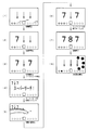
遊技盤6における下部の左側には、識別情報としての第1特別図柄を可変表示する第1特別図柄表示器(第1可変表示部)8aが設けられている。この実施の形態では、第1特別図柄表示器8aは、0〜9の数字を可変表示可能な簡易で小型の表示器(例えば7セグメントLED)で実現されている。すなわち、第1特別図柄表示器8aは、0〜9の数字(または、記号)を可変表示するように構成されている。遊技盤6における下部の右側には、識別情報としての第2特別図柄を可変表示する第2特別図柄表示器(第2可変表示部)8bが設けられている。第2特別図柄表示器8bは、0〜9の数字を可変表示可能な簡易で小型の表示器(例えば7セグメントLED)で実現されている。すなわち、第2特別図柄表示器8bは、0〜9の数字(または、記号)を可変表示するように構成されている。
On the left side of the lower part of the
小型の表示器は、例えば方形状に形成されている。また、この実施の形態では、第1特別図柄の種類と第2特別図柄の種類とは同じ(例えば、ともに0〜9の数字)であるが、種類が異なっていてもよい。また、第1特別図柄表示器8aおよび第2特別図柄表示器8bは、それぞれ、例えば、00〜99の数字(または、2桁の記号)を可変表示するように構成されていてもよい。
The small display is formed in a square shape, for example. In this embodiment, the type of the first special symbol and the type of the second special symbol are the same (for example, both 0 to 9), but the types may be different. Further, the first
以下、第1特別図柄と第2特別図柄とを特別図柄と総称することがあり、第1特別図柄表示器8aと第2特別図柄表示器8bとを特別図柄表示器(可変表示部)と総称することがある。
Hereinafter, the first special symbol and the second special symbol may be collectively referred to as a special symbol, and the first
なお、この実施の形態では、2つの特別図柄表示器8a,8bを備える場合を示しているが、遊技機は、特別図柄表示器を1つのみ備えるものであってもよい。
Although this embodiment shows a case where two
第1特別図柄または第2特別図柄の可変表示は、可変表示の実行条件である第1始動条件または第2始動条件が成立(例えば、遊技球が第1始動入賞口13または第2始動入賞口14を通過(入賞を含む)したこと)した後、可変表示の開始条件(例えば、保留記憶数が0でない場合であって、第1特別図柄および第2特別図柄の可変表示が実行されていない状態であり、かつ、大当り遊技が実行されていない状態)が成立したことにもとづいて開始され、可変表示時間(変動時間)が経過すると表示結果(停止図柄)を導出表示する。なお、遊技球が通過するとは、入賞口やゲートなどのあらかじめ入賞領域として定められている領域を遊技球が通過したことであり、入賞口に遊技球が入った(入賞した)ことを含む概念である。また、表示結果を導出表示するとは、図柄(識別情報の例)を最終的に停止表示させることである。
For the variable display of the first special symbol or the second special symbol, the first start condition or the second start condition, which is the variable display execution condition, is satisfied (for example, the game ball has the first
演出表示装置9の下方には、第1始動入賞口13を有する入賞装置が設けられている。第1始動入賞口13に入賞した遊技球は、遊技盤6の背面に導かれ、第1始動口スイッチ13aによって検出される。
A winning device having a first
また、第1始動入賞口(第1始動口)13を有する入賞装置の下方には、遊技球が入賞可能な第2始動入賞口14を有する可変入賞球装置15が設けられている。第2始動入賞口(第2始動口)14に入賞した遊技球は、遊技盤6の背面に導かれ、第2始動口スイッチ14aによって検出される。可変入賞球装置15は、ソレノイド16によって開状態とされる。可変入賞球装置15が開状態になることによって、遊技球が第2始動入賞口14に入賞可能になり(始動入賞し易くなり)、遊技者にとって有利な状態になる。可変入賞球装置15が開状態になっている状態では、第1始動入賞口13よりも、第2始動入賞口14に遊技球が入賞しやすい。また、可変入賞球装置15が閉状態になっている状態では、遊技球は第2始動入賞口14に入賞しない。従って、可変入賞球装置15が閉状態になっている状態では、第2始動入賞口14よりも、第1始動入賞口13に遊技球が入賞しやすい。なお、可変入賞球装置15が閉状態になっている状態において、入賞はしづらいものの、入賞することは可能である(すなわち、遊技球が入賞しにくい)ように構成されていてもよい。
A variable winning
以下、第1始動入賞口13と第2始動入賞口14とを総称して始動入賞口または始動口ということがある。
Hereinafter, the first
可変入賞球装置15が開放状態に制御されているときには可変入賞球装置15に向かう遊技球は第2始動入賞口14に極めて入賞しやすい。そして、第1始動入賞口13は演出表示装置9の直下に設けられているが、演出表示装置9の下端と第1始動入賞口13との間の間隔をさらに狭めたり、第1始動入賞口13の周辺で釘を密に配置したり、第1始動入賞口13の周辺での釘配列を遊技球を第1始動入賞口13に導きづらくして、第2始動入賞口14の入賞率の方を第1始動入賞口13の入賞率よりもより高くするようにしてもよい。
When the variable winning
なお、この実施の形態では、図1に示すように、第2始動入賞口14に対してのみ開閉動作を行う可変入賞球装置15が設けられているが、第1始動入賞口13および第2始動入賞口14のいずれについても開閉動作を行う可変入賞球装置が設けられている構成であってもよい。
In this embodiment, as shown in FIG. 1, the variable winning
第1特別図柄表示器8aの側方には、第1始動入賞口13に入った有効入賞球数すなわち第1保留記憶数(保留記憶を、始動記憶または始動入賞記憶ともいう。)を表示する4つの表示器からなる第1特別図柄保留記憶表示器18aが設けられている。第1特別図柄保留記憶表示器18aは、有効始動入賞がある毎に、点灯する表示器の数を1増やす。そして、第1特別図柄表示器8aでの可変表示が開始される毎に、点灯する表示器の数を1減らす。
On the side of the first
第2特別図柄表示器8bの側方には、第2始動入賞口14に入った有効入賞球数すなわち第2保留記憶数を表示する4つの表示器からなる第2特別図柄保留記憶表示器18bが設けられている。第2特別図柄保留記憶表示器18bは、有効始動入賞がある毎に、点灯する表示器の数を1増やす。そして、第2特別図柄表示器8bでの可変表示が開始される毎に、点灯する表示器の数を1減らす。
On the side of the second
また、演出表示装置9の表示画面の下部には、第1保留記憶数を表示する第1保留記憶表示部9aと第2保留記憶数を表示する第2保留記憶表示部9bとが設けられている。なお、この実施の形態では、第1保留記憶数と第2保留記憶数とを個別に表示する場合を示しているが、第1保留記憶数と第2保留記憶数との合計数である合算保留記憶数を表示する合算保留記憶表示部を設けるように構成してもよい。そのように構成すれば、可変表示の開始条件が成立していない実行条件の成立数の合計を把握しやすくすることができる。また、そのように構成した場合に、合算保留記憶表示部において、第1保留記憶と第2保留記憶とが第1始動入賞口13および第2始動入賞口14への入賞順に並べて表示されるとともに、第1保留記憶であるか第2保留記憶であるかを認識可能な態様で表示される(例えば、第1保留記憶は赤色で表示され、第2保留記憶は青色で表示される)ように構成してもよい。
In addition, at the lower part of the display screen of the
演出表示装置9は、第1特別図柄表示器8aによる第1特別図柄の可変表示時間中、および第2特別図柄表示器8bによる第2特別図柄の可変表示時間中に、装飾用(演出用)の図柄としての演出図柄の可変表示を行う。第1特別図柄表示器8aにおける第1特別図柄の可変表示と、演出表示装置9における演出図柄の可変表示とは同期している。また、第2特別図柄表示器8bにおける第2特別図柄の可変表示と、演出表示装置9における演出図柄の可変表示とは同期している。また、第1特別図柄表示器8aにおいて大当り図柄が停止表示されるときと、第2特別図柄表示器8bにおいて大当り図柄が停止表示されるときには、演出表示装置9において大当りを想起させるような演出図柄の組み合わせが停止表示される。
The
なお、この実施の形態では、後述するように、特別図柄の変動表示を制御する遊技制御用マイクロコンピュータ560が変動時間を特定可能な変動パターンコマンドを送信し、演出制御用マイクロコンピュータ100によって、受信した変動パターンコマンドで特定される変動時間に従って演出図柄の変動表示が制御される。そのため、変動パターンコマンドにもとづいて変動時間が特定されることから、特別図柄の変動表示と演出図柄の変動表示とは、原則として同期して実行されるはずである。ただし、万一変動パターンコマンドのデータ化けなどが生じた場合には、遊技制御用マイクロコンピュータ560側で認識している変動時間と、演出制御用マイクロコンピュータ100側で認識している変動時間との間にズレが生じる可能性がある。そのため、コマンドのデータ化けなどの不測の事態が生じた場合には、特別図柄の変動表示と演出図柄の変動表示とが完全には同期しない事態が生じる可能性がある。
In this embodiment, as will be described later, the
演出表示装置9の周囲の飾り部において、左側には、モータ86の回転軸に取り付けられ、モータ86が回転すると移動する可動部材78が設けられている。この実施の形態では、可動部材78は、予告演出(可動物予告演出)やスーパーリーチ演出が実行されるときに動作する。なお、可動物予告演出やスーパーリーチ演出にかぎらず、例えば、擬似連の演出において可動部材78が動作するようにしてもよい。
On the left side of the decorative portion around the
また、演出表示装置9の周囲の飾り部において、左右の下方には、モータ87の回転軸に取り付けられ、モータ87が回転すると移動する羽根形状の可動部材(以下、演出羽根役物という。)79a,79bが設けられている。演出羽根役物79a,79bは、例えば、予告演出(演出羽根役物予告演出)が実行されるときに動作する。なお、演出羽根役物予告演出にかぎらず、例えば、擬似連の演出やスーパーリーチ演出において演出羽根役物79a,79bが動作するようにしてもよい。
Further, in the decorative portion around the
また、図1に示すように、可変入賞球装置15の下方には、特別可変入賞球装置20が設けられている。特別可変入賞球装置20は開閉板を備え、第1特別図柄表示器8aに特定表示結果(大当り図柄)が導出表示されたときと、第2特別図柄表示器8bに特定表示結果(大当り図柄)が導出表示されたときに生起する特定遊技状態(大当り遊技状態)においてソレノイド21によって開閉板が開放状態に制御されることによって、入賞領域となる大入賞口が開放状態になる。大入賞口に入賞した遊技球はカウントスイッチ23で検出される。
Further, as shown in FIG. 1, a special variable winning
遊技領域6には、遊技球の入賞にもとづいてあらかじめ決められている所定数の景品遊技球の払出を行うための入賞口(普通入賞口)29,30,33,39も設けられている。入賞口29,30,33,39に入賞した遊技球は、入賞口スイッチ29a,30a,33a,39aで検出される。
The
遊技盤6の右側方には、普通図柄表示器10が設けられている。普通図柄表示器10は、普通図柄と呼ばれる複数種類の識別情報(例えば、「○」および「×」)を可変表示する。
A
遊技球がゲート32を通過しゲートスイッチ32aで検出されると、普通図柄表示器10の表示の可変表示が開始される。この実施の形態では、上下のランプ(点灯時に図柄が視認可能になる)が交互に点灯することによって可変表示が行われ、例えば、可変表示の終了時に下側のランプが点灯すれば当りとなる。そして、普通図柄表示器10における停止図柄が所定の図柄(当り図柄)である場合に、可変入賞球装置15が所定回数、所定時間だけ開状態になる。すなわち、可変入賞球装置15の状態は、普通図柄の停止図柄が当り図柄である場合に、遊技者にとって不利な状態から有利な状態(第2始動入賞口14に遊技球が入賞可能な状態)に変化する。普通図柄表示器10の近傍には、ゲート32を通過した入賞球数を表示する4つのLEDによる表示部を有する普通図柄保留記憶表示器41が設けられている。ゲート32への遊技球の通過がある毎に、すなわちゲートスイッチ32aによって遊技球が検出される毎に、普通図柄保留記憶表示器41は点灯するLEDを1増やす。そして、普通図柄表示器10の可変表示が開始される毎に、点灯するLEDを1減らす。さらに、通常状態に比べて大当りとすることに決定される確率が高い状態である高確率状態(通常状態と比較して、特別図柄の変動表示結果として大当りと判定される確率が高められた状態。ただし、後述する高確率/低ベース状態を除く。)では、普通図柄表示器10における停止図柄が当り図柄になる確率が高められるとともに、可変入賞球装置15の開放時間と開放回数が高められる。
When the game ball passes through the
遊技盤6の遊技領域7の左右周辺には、遊技中に点滅表示される装飾LED25が設けられ、下部には、入賞しなかった打球が取り込まれるアウト口26がある。また、遊技領域7の外側の左右上部には、所定の音声出力として効果音や音声を発声する2つのスピーカ27が設けられている。遊技領域7の外周には、前面枠に設けられた枠LED28が設けられている。
On the left and right sides of the
打球供給皿3を構成する部材においては、遊技者により操作可能な操作手段としての操作ボタン120が設けられている。操作ボタン120には、遊技者が押圧操作をすることが可能な押しボタンスイッチが設けられている。なお、操作ボタン120は、遊技者による押圧操作が可能な押しボタンスイッチが設けられているだけでなく、遊技者による回転操作が可能なダイヤルも設けられている。遊技者は、ダイヤルを回転操作することによって、所定の選択(例えば演出の選択)を行うことができる。
The members constituting the hitting
遊技機には、遊技者が打球操作ハンドル5を操作することに応じて駆動モータを駆動し、駆動モータの回転力を利用して遊技球を遊技領域7に発射する打球発射装置(図示せず)が設けられている。打球発射装置から発射された遊技球は、遊技領域7を囲むように円形状に形成された打球レールを通って遊技領域7に入り、その後、遊技領域7を下りてくる。遊技球が第1始動入賞口13に入り第1始動口スイッチ13aで検出されると、第1特別図柄の可変表示を開始できる状態であれば(例えば、特別図柄の可変表示が終了し、第1の開始条件が成立したこと)、第1特別図柄表示器8aにおいて第1特別図柄の可変表示(変動)が開始されるとともに、演出表示装置9において演出図柄の可変表示が開始される。すなわち、第1特別図柄および演出図柄の可変表示は、第1始動入賞口13への入賞に対応する。第1特別図柄の可変表示を開始できる状態でなければ、第1保留記憶数が上限値に達していないことを条件として、第1保留記憶数を1増やす。
In the gaming machine, a ball striking device (not shown) that drives a driving motor in response to a player operating the batting operation handle 5 and uses the rotational force of the driving motor to launch a gaming ball to the gaming area 7. ) Is provided. A game ball launched from the ball striking device enters the
遊技球が第2始動入賞口14に入り第2始動口スイッチ14aで検出されると、第2特別図柄の可変表示を開始できる状態であれば(例えば、特別図柄の可変表示が終了し、第2の開始条件が成立したこと)、第2特別図柄表示器8bにおいて第2特別図柄の可変表示(変動)が開始されるとともに、演出表示装置9において演出図柄の可変表示が開始される。すなわち、第2特別図柄および演出図柄の可変表示は、第2始動入賞口14への入賞に対応する。第2特別図柄の可変表示を開始できる状態でなければ、第2保留記憶数が上限値に達していないことを条件として、第2保留記憶数を1増やす。
When the game ball enters the second start winning opening 14 and is detected by the second
この実施の形態では、大当りとなった場合には、大当り遊技終了後にいわゆる確変状態に移行され、遊技状態を高確率状態に移行するとともに、遊技球が始動入賞しやすくなる(すなわち、特別図柄表示器8a,8bや演出表示装置9における可変表示の実行条件が成立しやすくなる)ように制御された遊技状態である高ベース状態に移行する。高ベース状態である場合には、例えば、高ベース状態でない場合と比較して、可変入賞球装置15が開状態となる頻度が高められたり、可変入賞球装置15が開状態となる時間が延長されたりして、始動入賞しやすくなる。なお、この実施の形態では、大当りとなった場合には必ず確変状態に移行されるのであるが、大当りとなった場合に、確変状態以外にいわゆる時短状態に移行される場合もあるように遊技機を構成してもよい。この場合、時短状態においても高ベース状態に移行されるようにしてもよい。
In this embodiment, when a big hit is made, the game is shifted to a so-called probability change state after the big hit game is finished, the game state is changed to a high probability state, and the game ball is easily started and won (that is, a special symbol display). Transition to the high base state, which is a gaming state controlled so that variable display execution conditions in the
なお、可変入賞球装置15が開状態となる時間を延長する(開放延長状態ともいう)のでなく、普通図柄表示器10における停止図柄が当り図柄になる確率が高められる普通図柄確変状態に移行することによって、高ベース状態に移行してもよい。普通図柄表示器10における停止図柄が所定の図柄(当り図柄)となると、可変入賞球装置15が所定回数、所定時間だけ開状態になる。この場合、普通図柄確変状態に移行制御することによって、普通図柄表示器10における停止図柄が当り図柄になる確率が高められ、可変入賞球装置15が開状態となる頻度が高まる。従って、普通図柄確変状態に移行すれば、可変入賞球装置15の開放時間と開放回数が高められ、始動入賞しやすい状態(高ベース状態)となる。すなわち、可変入賞球装置15の開放時間と開放回数は、普通図柄の停止図柄が当り図柄であったり、特別図柄の停止図柄が確変図柄である場合等に高められ、遊技者にとって不利な状態から有利な状態(始動入賞しやすい状態)に変化する。なお、開放回数が高められることは、閉状態から開状態になることも含む概念である。
Instead of extending the time during which the variable winning
また、普通図柄表示器10における普通図柄の変動時間(可変表示期間)が短縮される普通図柄時短状態に移行することによって、高ベース状態に移行してもよい。普通図柄時短状態では、普通図柄の変動時間が短縮されるので、普通図柄の変動が開始される頻度が高くなり、結果として普通図柄が当りとなる頻度が高くなる。従って、普通図柄が当たりとなる頻度が高くなることによって、可変入賞球装置15が開状態となる頻度が高くなり、始動入賞しやすい状態(高ベース状態)となる。
Moreover, you may transfer to a high base state by shifting to the normal symbol time short state where the fluctuation time (variable display period) of the normal symbol in the
また、特別図柄や演出図柄の変動時間(可変表示期間)が短縮される時短状態に移行することによって、特別図柄や演出図柄の変動時間が短縮されるので、特別図柄や演出図柄の変動が開始される頻度が高くなり(換言すれば、保留記憶の消化が速くなる。)、無効な始動入賞が生じてしまう事態を低減することができる。従って、有効な始動入賞が発生しやすくなり、結果として、大当り遊技が行われる可能性が高まる。 In addition, the change time of special symbols and production symbols will be shortened by shifting to the short time state when the variation time (variable display period) of special symbols and production symbols is shortened. The frequency of being played (in other words, the digestion of the reserved memory becomes faster), and the situation where an invalid start prize is generated can be reduced. Therefore, an effective start winning is likely to occur, and as a result, the possibility of a big hit game being increased.
さらに、上記に示した全ての状態(開放延長状態、普通図柄確変状態、普通図柄時短状態および特別図柄時短状態)に移行させることによって、始動入賞しやすくなる(高ベース状態に移行する)ようにしてもよい。また、上記に示した各状態(開放延長状態、普通図柄確変状態、普通図柄時短状態および特別図柄時短状態)のうちのいずれか複数の状態に移行させることによって、始動入賞しやすくなる(高ベース状態に移行する)ようにしてもよい。また、上記に示した各状態(開放延長状態、普通図柄確変状態、普通図柄時短状態および特別図柄時短状態)のうちのいずれか1つの状態にのみ移行させることによって、始動入賞しやすくなる(高ベース状態に移行する)ようにしてもよい。 Furthermore, by making transitions to all the states shown above (open extended state, normal symbol probability change state, normal symbol short time state, and special symbol short time state), it will be easier to win a start (shift to a high base state). May be. In addition, it becomes easier to win a start (high base) by shifting to any one of the above states (open extended state, normal symbol probability changing state, normal symbol short time state, and special symbol short time state). Transition to a state). In addition, it is easier to win a start by shifting to any one of the above states (open extended state, normal symbol probability changing state, normal symbol short time state, and special symbol short time state). You may make it move to a base state.
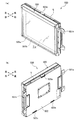
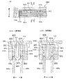
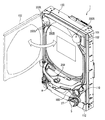
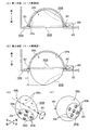
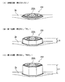
次に、表示ユニット550の構造について説明する。図2は、(a)は表示ユニットを斜め前方から見た状態を示す斜視図、(b)は斜め後方から見た状態を示す斜視図である。図3は、表示ユニットの内部構造を示す分解斜視図である。図4は、(a)は前導光板、(b)は後導光板、(c)はドットパターンを示す要部拡大図、(d)はドットパターンを示す拡大断面図である。図5は、上フレームの内部構造を示す分解斜視図である。図6は、(a)は集光レンズの平面図、(b)は集光レンズの正面図、(c)は(a)のA−A断面図、(d)は(a)のB−B断面図である。図7は、(a)は上フレームを示す要部拡大平面図、(b)は(a)のC−C断面図、(c)は(a)のD−D断面図である。図8は、表示ユニットを示す縦断面図である。図9は、図8の要部拡大断面図である。図10は、図8のE−E断面図である。
Next, the structure of the
なお、以下の説明においては、表示ユニット550を遊技機1の正面から見た場合を規準として上下左右方向を説明することとする。
In the following description, the vertical and horizontal directions will be described with reference to the case where the
図2および図3に示すように、表示ユニット550は、演出表示装置9と、演出表示装置9の前面側に配置された表示装置500と、が一体的に組み付けられてなる。演出表示装置9は、左右側辺に遊技機1に取り付けるための取付金具501a、501bが設けられた取付部材502の前面に取り付けられている。表示装置500は、演出表示装置9の表示領域の前面側を覆うように配置された状態で、上辺および下辺から背面側に向けて突設された係止爪503a〜503cを介して取付部材502に係止されている。
As shown in FIGS. 2 and 3, the
表示装置500は、光を透過可能な透光性を有する前導光板505aおよび後導光板505bからなる導光板505と、該導光板505の端面に光を入射可能に設けられる発光体としての表示用LED62a,62b(図5参照)と、導光板505の背面に所定の表示情報(図4参照)を表す態様にて設けられ、導光板505の端面から内部に入射された表示用LED62a,62bからの入射光を誘導して前面から出射させることで表示情報を表示する反射部510a〜510c、511と、導光板505と表示用LED62a,62bとの間に配置され、該表示用LED62a,62bからの入射光を導光板505側に誘導しながら板厚方向に集光して該導光板505の端面に向けて出射する前レンズ507aおよび後レンズ507bからなる集光レンズ507(図5参照)と、非透光性を有する合成樹脂材により四角枠状に形成されたフレーム枠体504と、から主に構成されている。
The
フレーム枠体504は、左フレーム504aおよび右フレーム504bと、これら左フレーム504aおよび右フレーム504bの下端間を連結する下フレーム504cおよび上端間を連結する上フレーム504dと、により四角枠状に形成されている。左フレーム504a、右フレーム504bおよび下フレーム504cは一体化され上向きコ字形に形成されているとともに、上フレーム504dは、左フレーム504aおよび右フレーム504bの上端にネジN1により着脱可能に取り付けられ、上辺を開放可能に設けられている。
The
左フレーム504a、右フレーム504bおよび下フレーム504cの内側面には、前導光板505aが差し込まれる差込溝508aと、後導光板505bが差し込まれる差込溝508bと、が長手方向にわたり連続して、かつ平行に形成されており、図3に示すように上フレーム504dを取り外すことで、導光板505を上方から差込溝508a、508b内に差し込みおよび上方に抜き取り可能とされている。
An
このように導光板505を左フレーム504a、右フレーム504bおよび下フレーム504cから取り外し可能に設けることで、導光板505を容易に交換することができるため、例えば表面が汚れたり傷付いたり、あるいは表示情報が異なる他の導光板505へ交換する場合において、導光板505のみを容易に交換することができる。
Since the light guide plate 505 is detachably provided from the
図4に示すように、前導光板505aおよび後導光板505bは、所定の前後幅寸法L3{板厚(例えば、5mm)}を有するアクリルやポリカーボネートなどの透明な合成樹脂板により正面視横長長方形状に形成されている。なお、導光板505は、透光性を有していれば必ずしも透明でなくてもよく、例えば着色されていてもよいし、半透明とされていてもよい。
As shown in FIG. 4, the front
前導光板505aの背面505Bには、表示用LED62aからの光を反射して前面505Fから出射させるための反射部510a〜510cが形成されている(図4(a)参照)。反射部510aは「大」、反射部510bは「当」、反射部510cは「り」の文字を表す態様に形成され、前面505Fを左右方向に3等分した左領域、中領域、右領域それぞれに収まるように配置されている。
Reflecting
また、後導光板505bの背面505Bには、表示用LED62bからの光を反射して前面505Fから出射させるための反射部511が形成されている(図4(b)参照)。反射部511は、一群の花のような態様に形成されている。
Further, on the
よって、これら反射部510a,510b,510cと反射部511とは、前導光板505aと後導光板505bとがフレーム枠体504に差し込まれた状態で前後に重畳する位置に配置される。
Therefore, the
これら反射部510a〜510c、511は、図4(c)(d)に示すように、導光板505内を導光される光の進行方向の断面視が一定ピッチの略三角波形状をなす凹凸状態(粗面)に形成されている。具体的には、スタンパーやインジェクションにより導光板505の背面505Bに凹凸部をつける成型方式にて構成されているが、例えばアクリル板に白色インクで反射ドットを印刷したシルク印刷方式や、アクリル板と反射板とをドット状の粘着材で貼り付けた貼着ドット方式や、溝加工方式等により反射部を構成してもよい。
As shown in FIGS. 4C and 4D, the reflecting
なお、この実施の形態では、導光板505の背面505Bにおける反射部510a〜510c、511を光の進行方向の断面視が略三角波形状の凹凸部としているが、本発明はこれに限定されるものではなく、これら反射部510a〜510c、511の断面形状を略半円形状等、光を前面505Fに向けて反射可能な反射面を構成するものであれば種々に変形可能である。なお、図4(a)(b)などにおいて、これら反射部510a〜510c、511は枠線で囲まれた文字や絵柄として表されているが、実際には枠線はなく、上記ドット等の集まりにより文字や絵柄が形成されている。
In this embodiment, the
また、この実施の形態では、導光板505により表示可能とする表示情報として、文字や絵柄が例示されているが、これら以外にも、記号、図柄、あるいは模様等の装飾も含む他の表示情報を表示可能としてもよい。以下、導光板505により文字や絵柄を表示する演出を導光板演出という。この実施の形態では、導光板演出は、保留予告演出の実行時や、大当り図柄が停止表示された時に実行される。なお、この実施の形態で示した場合にかぎらず、導光板演出は、例えば、スーパーリーチ時や、可動物予告演出の実行時、所定演出の実行時、大当り遊技状態中、大当り遊技後の高ベース状態中などの他に特別図柄変動中の任意のタイミングで実行されるようにしてもよい。 In this embodiment, characters and pictures are exemplified as display information that can be displayed by the light guide plate 505, but other display information including decorations such as symbols, patterns, or patterns is also included. Can be displayed. Hereinafter, an effect of displaying characters and designs by the light guide plate 505 is referred to as a light guide plate effect. In this embodiment, the light guide plate effect is executed when the hold notice effect is executed or when the big hit symbol is stopped and displayed. Note that the light guide plate effect is not limited to the case shown in this embodiment, for example, at the time of super reach, at the time of execution of the moving object notice effect, at the time of execution of the predetermined effect, during the big hit game state, after the big hit game It may be executed at an arbitrary timing during the special symbol change in addition to during the base state.
図5および図7に示すように、上フレーム504cには、左右方向に延設されるとともに上下方向に貫通される前後一対のレンズ溝512a、512bが形成されている。レンズ溝512a、512bは、中央の壁部513を挟んで前後に隔てて並設され、上方から下方に向けて漸次前後幅寸法が小さくなるようにテーパ状に形成されている。また、壁部513の左右端部には、レンズ溝512a、512bそれぞれに臨む前後一対の係止爪517a、517bが設けられており、レンズ溝512a、512bに嵌合された集光レンズ507の上端を係止して、上方への移動を規制するようになっている。
As shown in FIGS. 5 and 7, the
また、上フレーム504cの上面開口には、表示用LED62a、62bが下面に設けられたLED基板514が嵌合可能な凹状の基板配置部515が形成されている。この基板配置部515に、LED基板514を配置することで、前後のレンズ溝512a、512bの上面開口に表示用LED62a、62bが対向して配置され、その左右端部に取り付けたネジN2をネジ穴516a、516bに螺入することでLED基板514を固定できるようになっている。
In addition, a concave
図5および図6に示すように、前レンズ507aおよび後レンズ507bは、アクリルまたはポリカーボネート等の透光性を有する合成樹脂材により横長板状に形成され、導光板505の上端面505Hに沿うように延設され、導光板505の上端面505Hと表示用LED62a、62bとの間に配設される(図10参照)。
As shown in FIGS. 5 and 6, the
具体的には、前レンズ507aおよび後レンズ507bの下辺部には、正面視で下向きに膨出する略半円形状の複数の凸部518が長手方向に複数連続して並設されている。各凸部518は、表示用LED62a、62b各々に対応して1つずつ形成され、各凸部518の先端面、つまり前レンズ507aおよび後レンズ507bにおいて導光板505の上端面505Hに対向する下端面507L(出射面)は、複数の湾曲面(レンズ面)を構成している。
Specifically, a plurality of substantially semicircular
なお、複数の凸部518は表示用LEDに一対一に対応するものに限らず、例えば2以上のLED(発光体)に対応する凸部518(レンズ面)が複数設けられていてもよい。また、前レンズ507aおよび後レンズ507bは複数の凸部518が一体に設けられた単一の部材にて構成されていたが、上端面505Hに沿って複数並設される表示用LED62a、62b各々に対応して、互いに別個に形成された複数の集光レンズを配設してもよい。
Note that the plurality of
前レンズ507aおよび後レンズ507bの上辺部には、正面視で上向きに僅かに膨出する湾曲形状の膨出部519が長手方向に複数連続して形成されている。各膨出部519は、表示用LED62a、62b各々に対応して1つずつ形成され、各膨出部519の先端面、つまり前レンズ507aおよび後レンズ507bにおいて表示用LED62a、62bに対向する上端面507H(入射面)は、複数の湾曲面(レンズ面)を構成している。なお、湾曲状の上端面507Hは、湾曲状の下端面507Lに比べて曲率は小さく、僅かに膨出する程度に形成されている。
On the upper sides of the
また、前レンズ507aおよび後レンズ507bの下端面507Lにおける最下位部の前後幅寸法L1(板厚)は、上端面507Hの最上位部の前後幅寸法L2(板厚)よりも短寸とされている(L1<L2)。また、下端面507Lの前後幅寸法L1は、導光板505の前後幅寸法L3とほぼ同寸とされ(L1≒L3)、上端面507Hの前後幅寸法L2は、表示用LED62a、62bの発光面62cの前後幅寸法L4(図9参照)とほぼ同寸に形成されている。
The front-rear width dimension L1 (plate thickness) of the lowermost portion of the
そして、前面507Fは、上端面507Hから下端面507Lに向けて漸次後側に傾斜する平坦な傾斜面を構成し、背面507Bは、上端面507Hから下端面507Lに向けて漸次前側に傾斜する平坦な傾斜面を構成している。つまり、前面507Fおよび背面507Bは、上端面507Hから下端面507Lに向けて漸次互いに近づく方向に傾斜する傾斜面を構成しているため、前レンズ507aおよび後レンズ507bは、上端面507Hから下端面507Lに向けて漸次板厚が薄くなる縦断面視略逆ハの字状に形成されている。
The
よって、前レンズ507aおよび後レンズ507bの下端面507Lの前後幅寸法(板厚)は、各凸部518における最下位部に近づくにつれて短寸となり、最下位部において前後幅寸法L1が最小となる。なお、この実施の形態では、上端面507Hと傾斜面との間に互いに平行をなす短寸の非傾斜面507Fa、507Bbが設けられている。
Therefore, the front-rear width dimension (plate thickness) of the
前レンズ507aおよび後レンズ507bの左右端部にはフック片520a、520bが形成されており、上フレーム504d内に設けられたリブ(図示略)に上方から係止され、レンズ溝512a、512b内に保持されるようになっている。
図7に示すように、このように構成された前レンズ507aおよび後レンズ507bは、上フレーム504dの上面開口から前後のレンズ溝512a、512b内に上方から差し込まれる。そして、上端面507Hがレンズ溝512a、512bの上面開口とほぼ同高さ位置に位置するまで差し込まれ、フック片520a、520bがリブ(図示略)に係止された状態において、下端面507Lはレンズ溝512a、512bの下面開口よりもやや上方位置に位置し、レンズ溝512a、512b内下部に、導光板505が差し込まれる凹溝部が形成されるようになっている。
As shown in FIG. 7, the thus configured
実際には、上フレーム504dを左フレーム504aおよび右フレーム504bの上端間に連結したときに、前導光板505aおよび後導光板505bがレンズ溝512a、512b内下部に差し込まれる。このように、前導光板505aおよび後導光板505bがレンズ溝512a、512b内下部に差し込まれることで、前導光板505aおよび後導光板505bの上端面505Hと、前レンズ507aおよび後レンズ507bの下端面507Lとは、レンズ溝512a、512b内にて所定の隙間を隔てて対峙する。このように前導光板505aおよび後導光板505bがレンズ溝512a、512b内下部に嵌合されることで、上端面505Hと下端面507Lとの前後方向の位置ずれが防止される。
Actually, when the
また、特に図7(c)に示すように、凸部518により下端面507Lが湾曲面にて形成されていることで、下端面507Lと上端面505Hとの間に空間部が形成されるが、レンズ溝512a、512bを構成する上フレーム504dの非透光性壁面によりこの空間部が密封されることで、下端面507Lから出射される光が周囲に漏出することなく上端面505Hに入射される。なお、この実施の形態で示す例に限らず、同じ効果を得るために、例えば、上端面507Hや上端面505Hが、凹面となるように形成されていたり、ローレット形状に加工されていてもよい。
In particular, as shown in FIG. 7C, a space is formed between the
図8に示すように、このように構成された表示装置500は、演出表示装置9の前面側に組み付けられる(図2参照)。前面側に組み付けられた状態において、フレーム枠体504により演出表示装置9の表示領域の周囲が囲まれるとともに、前後一対の導光板507により演出表示装置9の表示領域が全て覆われる。
As shown in FIG. 8, the
また、後導光板505bは、演出表示装置9の表示領域に対して所定の隙間(例えば、約20mm)を隔てて前面側に配置され、前導光板505aは、後導光板505bに対して所定の隙間(例えば、約15mm)を隔てて前面側に配置される。なお、この隙間幅は種々に変更可能である。また、前導光板505aと後導光板505bとを互いに当接させた状態で配置してもよい。
In addition, the rear
また、演出表示装置9と表示装置500とは別個に構成され、互いに着脱可能に組み付けられて一体化できるようになっていることで、演出表示装置9と表示装置500とを一体化した状態で遊技機1に組み付けたり取り外したりすることができるため、作業性が向上するばかりか、遊技機1への組み付け時に演出表示装置9と表示装置500との相対位置にずれなどが生じることがない。
In addition, the
また、演出表示装置9と前後の導光板507および表示用LED62a、62bの交換作業等を互いに分離した状態で別個に行うことができるため、交換作業が容易になる。さらに表示装置500は、導光板505、LED基板514、集光レンズ507などがフレーム枠体504を介して一体化されていることで、演出表示装置9から分離しても各部材の相対位置関係が変わることがないため、作業性が向上するとともに、交換による取り外しにより各部材の相対位置関係が変化して発光表示に悪影響が及ぶことがない。
In addition, the replacement operation of the
次に、図9および図10に示すように、表示装置500は、集光レンズ507、LED基板514、導光板505がフレーム枠体504に一体に組み付けられた状態において、前導光板505aの上辺に沿って前レンズ507aが配設され、前レンズ507aの上方位置に複数の表示用LED62aが長手方向に並設されるとともに、後導光板505bの上辺に沿って後レンズ507bが配設され、後レンズ507bの上方位置に複数の表示用LED62bが長手方向に並設される。つまり、導光板505と表示用LED62a、62bとの間に集光レンズ507が配設される。
Next, as shown in FIGS. 9 and 10, the
具体的には、集光レンズ507は、下端面507Lが導光板505の上端面505Hに対向し、上端面507Hが各表示用LED62a、62bの発光面62cに対向する。また、各表示用LED62a、62bは、各凸部518に対応する個々の上端面507Hおよび下端面507Lの左右方向の略中央位置に配置される。
Specifically, in the
そして、上端面507Hの前後幅寸法L2と発光面62cの前後幅寸法L4とはほぼ同寸であり(L2≒L4)、発光面62cと上端面507Hとの前後方向のずれはないことで、発光面62cからの出射光は前後方向に拡散されることなく上端面507Hに入射される。また、上端面505Hの前後幅寸法L3は下端面507Lの最下位部付近の前後幅寸法L1とほぼ同寸であり(L3≒L1)、上端面505Hと下端面507Lとの前後方向のずれはないことで、下端面507Lからの出射光は前後方向に拡散されることなく上端面505Hに入射される。
The front-rear width dimension L2 of the
また、下端面507Lの最下位部と上端面505Hとの間および上端面507Hと表示用LED62a,62bの発光面62cとの間には、所定の隙間(例えば、約1〜3mm程度)が設けられる。これにより、遊技機の輸送や使用の際に生じる振動により集光レンズ507や導光板505に傷が付くことが防止されている。
Further, a predetermined gap (for example, about 1 to 3 mm) is provided between the lowermost portion of the
次に、表示用LED62a,62bからの出射光の導光状態について説明する。
Next, the light guide state of the emitted light from the
各表示用LED62a,62bから出射された出射光は、集光レンズ507の上端面507H内に入射される。ここで、上端面507Hの前後幅寸法L2と発光面62cの前後幅寸法L4とはほぼ同寸であるため(L2≒L4)、各表示用LED62a,62bからの出射光は、前後方向に拡散せずにほぼ上端面507H内に入射される。また、上端面507Hの左右幅は発光面62cの左右幅よりも長寸であるため、左右方向に拡散される光もほぼ上端面507H内に入射される。
The outgoing light emitted from each of the
上端面507Hから集光レンズ507内に入射された入射光は、下方の導光板505に向けて誘導される。LEDの光は指向性が高いが、レンズ面をなすように湾曲状に形成された上端面507Hを通して入射されることで、入射光は左右方向に放射状に拡散される。そして、同じように湾曲状のレンズ面として形成された下端面507Lを通過する際に、鉛直下方に向けて屈折して出射されるようになっている(図10参照)。
Incident light that enters the
これにより、指向性が高い表示用LED62a,62bからの出射光を、集光レンズ507によりある程度左右方向に放射状に拡散させて発光領域を広げることが可能となるとともに、下端面507Lにおける左右方向の異なる位置から出射される光は鉛直下方に導光されて放射状に拡がることはないので、各表示用LED62a,62bに対応する鉛直下方領域のみを部分的に発光させることが可能となる。
As a result, the light emitted from the
また、上端面507Hから集光レンズ507内に入射された入射光は、下方の導光板505に向けて誘導されながら、前後(板厚)方向に全反射を繰り返し、該前後方向の略中央位置に向けて集光され(図9参照)、最終的に上端面507Hよりも前後幅が短い下端面507Lから出射される。
Further, the incident light that has entered the
このように、表示用LED62a,62bからの光を前後幅(板厚)方向に拡散させることなく集光して導光板505の上端面505Hに導くことができるため、光の減衰が抑制される。特に、表示用LED62a,62bの発光面62cの前後幅寸法L4が、上端面505Hの前後幅寸法L3よりも大きい場合(L4>L3)であっても、表示用LED62a,62bからの光を前後幅(板厚)方向に拡散させることなく導光板505の上端面505Hに導くことができるため、表示用LED62a,62bからの光が周囲に拡散されることが防止される。
In this way, the light from the
また、特に図示しないが、例えば表示用LED62a,62bが前後幅方向に複数配置される場合でも、上端面507Hの前後幅寸法L2を表示用LED62a,62bに応じて拡げ、これにより出射光を周囲に拡散させずに上端面507Hに入射させることができる。よって、導光板505の前後幅寸法L3(板厚)よりも表示用LED62a,62bの発光領域の前後幅寸法が大きい場合でも、表示用LED62a,62bからの出射光を誘導しながら板厚方向に集光して導光板505内に入射させることができる。
Although not specifically shown, for example, even when a plurality of
下端面507Lから出射された光は、導光板505の上端面505Hに入射され、前後面により全反射を繰り返しながら下方に誘導されていく。そして、反射部510a〜510c、511に到達したときに、凹部により形成された反射面にて入射光が前面側に向けて反射されることで、遊技者からは、それぞれの反射部510a〜510c、511に対応する箇所が反射光により発光されることで、所定の文字やキャラクタ等の表示情報が表示されるようになる。
The light emitted from the
図11は、主基板(遊技制御基板)31における回路構成の一例を示すブロック図である。なお、図11は、払出制御基板37および演出制御基板80等も示されている。主基板31には、プログラムに従ってパチンコ遊技機1を制御する遊技制御用マイクロコンピュータ(遊技制御手段に相当)560が搭載されている。遊技制御用マイクロコンピュータ560は、ゲーム制御(遊技進行制御)用のプログラム等を記憶するROM54、ワークメモリとして使用される記憶手段としてのRAM55、プログラムに従って制御動作を行うCPU56およびI/Oポート部57を含む。この実施の形態では、ROM54およびRAM55は遊技制御用マイクロコンピュータ560に内蔵されている。すなわち、遊技制御用マイクロコンピュータ560は、1チップマイクロコンピュータである。1チップマイクロコンピュータには、少なくともCPU56のほかRAM55が内蔵されていればよく、ROM54は外付けであっても内蔵されていてもよい。また、I/Oポート部57は、外付けであってもよい。遊技制御用マイクロコンピュータ560には、さらに、ハードウェア乱数(ハードウェア回路が発生する乱数)を発生する乱数回路53が内蔵されている。
FIG. 11 is a block diagram showing an example of the circuit configuration of the main board (game control board) 31. As shown in FIG. FIG. 11 also shows the
また、RAM55は、その一部または全部が電源基板910において作成されるバックアップ電源によってバックアップされている不揮発性記憶手段としてのバックアップRAMである。すなわち、遊技機に対する電力供給が停止しても、所定期間(バックアップ電源としてのコンデンサが放電してバックアップ電源が電力供給不能になるまで)は、RAM55の一部または全部の内容は保存される。特に、少なくとも、遊技状態すなわち遊技制御手段の制御状態に応じたデータ(特別図柄プロセスフラグなど)と未払出賞球数を示すデータは、バックアップRAMに保存される。遊技制御手段の制御状態に応じたデータとは、停電等が生じた後に復旧した場合に、そのデータにもとづいて、制御状態を停電等の発生前に復旧させるために必要なデータである。また、制御状態に応じたデータと未払出賞球数を示すデータとを遊技の進行状態を示すデータと定義する。なお、この実施の形態では、RAM55の全部が、電源バックアップされているとする。 The RAM 55 is a backup RAM as a non-volatile storage means, part or all of which is backed up by a backup power source created on the power supply substrate 910. That is, even if the power supply to the gaming machine is stopped, a part or all of the contents of the RAM 55 is stored for a predetermined period (until the capacitor as the backup power supply is discharged and the backup power supply cannot be supplied). In particular, at least data (a special symbol process flag or the like) corresponding to the game state, that is, the control state of the game control means, and data indicating the number of unpaid winning balls are stored in the backup RAM. The data corresponding to the control state of the game control means is data necessary for restoring the control state before the occurrence of a power failure or the like based on the data when the power is restored after a power failure or the like occurs. Further, data corresponding to the control state and data indicating the number of unpaid prize balls are defined as data indicating the progress state of the game. In this embodiment, it is assumed that the entire RAM 55 is backed up.
なお、遊技制御用マイクロコンピュータ560においてCPU56がROM54に格納されているプログラムに従って制御を実行するので、以下、遊技制御用マイクロコンピュータ560(またはCPU56)が実行する(または、処理を行う)ということは、具体的には、CPU56がプログラムに従って制御を実行することである。このことは、主基板31以外の他の基板に搭載されているマイクロコンピュータについても同様である。
In the
乱数回路53は、特別図柄の可変表示の表示結果により大当りとするか否か判定するための判定用の乱数を発生するために用いられるハードウェア回路である。乱数回路53は、初期値(例えば、0)と上限値(例えば、65535)とが設定された数値範囲内で、数値データを、設定された更新規則に従って更新し、ランダムなタイミングで発生する始動入賞時が数値データの読出(抽出)時であることにもとづいて、読出される数値データが乱数値となる乱数発生機能を有する。 The random number circuit 53 is a hardware circuit that is used to generate a random number for determination for determining whether or not to win a jackpot based on a display result of variable symbol special display. The random number circuit 53 updates numerical data in accordance with a set update rule within a numerical range in which an initial value (for example, 0) and an upper limit value (for example, 65535) are set, and starts at a random timing Based on the fact that the winning time is the reading (extraction) of the numerical data, it has a random number generation function in which the numerical data to be read becomes a random value.
乱数回路53は、数値データの更新範囲の選択設定機能(初期値の選択設定機能、および、上限値の選択設定機能)、数値データの更新規則の選択設定機能、および数値データの更新規則の選択切換え機能等の各種の機能を有する。このような機能によって、生成する乱数のランダム性を向上させることができる。 The random number circuit 53 has a numeric data update range selection / setting function (initial value selection / setting function and upper limit selection / setting function), numeric data update rule selection / setting function, and numeric data update rule selection. It has various functions such as a switching function. With such a function, the randomness of the generated random numbers can be improved.
また、遊技制御用マイクロコンピュータ560は、乱数回路53が更新する数値データの初期値を設定する機能を有している。例えば、ROM54等の所定の記憶領域に記憶された遊技制御用マイクロコンピュータ560のIDナンバ(遊技制御用マイクロコンピュータ560の各製品ごとに異なる数値で付与されたIDナンバ)を用いて所定の演算を行なって得られた数値データを、乱数回路53が更新する数値データの初期値として設定する。そのような処理を行うことによって、乱数回路53が発生する乱数のランダム性をより向上させることができる。
Further, the
また、ゲートスイッチ32a、始動口スイッチ13a、カウントスイッチ23、入賞口スイッチ29a,30a,33a,39aからの検出信号を遊技制御用マイクロコンピュータ560に与える入力ドライバ回路58も主基板31に搭載されている。また、可変入賞球装置15を開閉するソレノイド16、および大入賞口を形成する特別可変入賞球装置20を開閉するソレノイド21を遊技制御用マイクロコンピュータ560からの指令に従って駆動する出力回路59も主基板31に搭載されている。
Further, an
また、遊技制御用マイクロコンピュータ560は、特別図柄を可変表示する第1特別図柄表示器8a、第2特別図柄表示器8b、普通図柄を可変表示する普通図柄表示器10、第1特別図柄保留記憶表示器18a、第2特別図柄保留記憶表示器18bおよび普通図柄保留記憶表示器41の表示制御を行う。
In addition, the
なお、大当り遊技状態の発生を示す大当り情報等の情報出力信号をホールコンピュータ等の外部装置に対して出力する情報出力回路(図示せず)も主基板31に搭載されている。
An information output circuit (not shown) that outputs an information output signal such as jackpot information indicating the occurrence of a jackpot gaming state to an external device such as a hall computer is also mounted on the
この実施の形態では、演出制御基板80に搭載されている演出制御手段(演出制御用マイクロコンピュータで構成される。)が、中継基板77を介して遊技制御用マイクロコンピュータ560から演出内容を指示する演出制御コマンドを受信し、演出図柄を可変表示する演出表示装置9の表示制御を行う。
In this embodiment, the effect control means (configured by the effect control microcomputer) mounted on the
また、演出制御基板80に搭載されている演出制御手段が、ランプドライバ基板35を介して、前導光板505aに対応する表示用LED62a、後導光板505bに対応する表示用LED62b、および遊技盤に設けられている装飾LED25、および枠側に設けられている枠LED28の表示制御を行うとともに、音声出力基板70を介してスピーカ27からの音出力の制御を行う。
The effect control means mounted on the
図12は、中継基板77、演出制御基板80、ランプドライバ基板35および音声出力基板70の回路構成例を示すブロック図である。なお、図12に示す例では、ランプドライバ基板35および音声出力基板70には、マイクロコンピュータは搭載されていないが、マイクロコンピュータを搭載してもよい。また、ランプドライバ基板35および音声出力基板70を設けずに、演出制御に関して演出制御基板80のみを設けてもよい。
FIG. 12 is a block diagram illustrating a circuit configuration example of the
演出制御基板80は、演出制御用CPU101、および演出図柄プロセスフラグ等の演出に関する情報を記憶するRAMを含む演出制御用マイクロコンピュータ100を搭載している。なお、RAMは外付けであってもよい。この実施の形態では、演出制御用マイクロコンピュータ100におけるRAMは電源バックアップされていない。演出制御基板80において、演出制御用CPU101は、内蔵または外付けのROM(図示せず)に格納されたプログラムに従って動作し、中継基板77を介して入力される主基板31からの取込信号(演出制御INT信号)に応じて、入力ドライバ102および入力ポート103を介して演出制御コマンドを受信する。また、演出制御用CPU101は、演出制御コマンドにもとづいて、VDP(ビデオディスプレイプロセッサ)109に演出表示装置9の表示制御を行わせる。
The
この実施の形態では、演出制御用マイクロコンピュータ100と共動して演出表示装置9の表示制御を行うVDP109が演出制御基板80に搭載されている。VDP109は、演出制御用マイクロコンピュータ100とは独立したアドレス空間を有し、そこにVRAMをマッピングする。VRAMは、画像データを展開するためのバッファメモリである。そして、VDP109は、VRAM内の画像データをフレームメモリを介して演出表示装置9に出力する。
In this embodiment, a
演出制御用CPU101は、受信した演出制御コマンドに従ってCGROM(図示せず)から必要なデータを読み出すための指令をVDP109に出力する。CGROMは、演出表示装置9に表示されるキャラクタ画像データや動画像データ、具体的には、人物、文字、図形や記号等(演出図柄を含む)、および背景画像のデータをあらかじめ格納しておくためのROMである。VDP109は、演出制御用CPU101の指令に応じて、CGROMから画像データを読み出す。そして、VDP109は、読み出した画像データにもとづいて表示制御を実行する。
The
演出制御コマンドおよび演出制御INT信号は、演出制御基板80において、まず、入力ドライバ102に入力する。入力ドライバ102は、中継基板77から入力された信号を演出制御基板80の内部に向かう方向にしか通過させない(演出制御基板80の内部から中継基板77への方向には信号を通過させない)信号方向規制手段としての単方向性回路でもある。
The effect control command and the effect control INT signal are first input to the
中継基板77には、主基板31から入力された信号を演出制御基板80に向かう方向にしか通過させない(演出制御基板80から中継基板77への方向には信号を通過させない)信号方向規制手段としての単方向性回路74が搭載されている。単方向性回路として、例えばダイオードやトランジスタが使用される。図12には、ダイオードが例示されている。また、単方向性回路は、各信号毎に設けられる。さらに、単方向性回路である出力ポート571を介して主基板31から演出制御コマンドおよび演出制御INT信号が出力されるので、中継基板77から主基板31の内部に向かう信号が規制される。すなわち、中継基板77からの信号は主基板31の内部(遊技制御用マイクロコンピュータ560側)に入り込まない。なお、出力ポート571は、図11に示されたI/Oポート部57の一部である。また、出力ポート571の外側(中継基板77側)に、さらに、単方向性回路である信号ドライバ回路が設けられていてもよい。
As a signal direction regulating means, the signal inputted from the
また、演出制御用CPU101は、出力ポート106を介して、可動部材78を動作させるためにモータ86を駆動する。また、演出制御用CPU101は、出力ポート106を介して、演出羽根役物79a,79bを動作させるためのモータ87を駆動する。
The
また、演出制御用CPU101は、入力ポート107を介して、遊技者による操作ボタン120の押圧操作に応じて操作ボタン120からの信号を入力する。
Further, the
さらに、演出制御用CPU101は、出力ポート105を介してランプドライバ基板35に対してLEDやランプを駆動する信号を出力する。また、演出制御用CPU101は、出力ポート104を介して音声出力基板70に対して音番号データを出力する。
Further, the
ランプドライバ基板35において、LEDやランプを駆動する信号は、入力ドライバ351を介してLED/ランプドライバ352に入力される。LED/ランプドライバ352は、LEDやランプを駆動する信号にもとづいて枠LED28などの枠側に設けられている発光体に電流を供給する。また、遊技盤側に設けられている装飾LED25などに電流を供給する。また、前導光板505aに対応する表示用LED62aや、後導光板505bに対応する表示用LED62bなどに電流を供給する。
In the
音声出力基板70において、音番号データは、入力ドライバ702を介して音声合成用IC703に入力される。音声合成用IC703は、音番号データに応じた音声や効果音を発生し増幅回路705に出力する。増幅回路705は、音声合成用IC703の出力レベルを、ボリューム706で設定されている音量に応じたレベルに増幅した音声信号をスピーカ27に出力する。音声データROM704には、音番号データに応じた制御データが格納されている。音番号データに応じた制御データは、所定期間(例えば演出図柄の変動期間)における効果音または音声の出力態様を時系列的に示すデータの集まりである。
In the
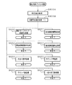
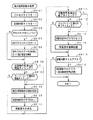
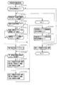
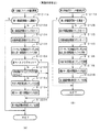
次に、遊技機の動作について説明する。図13は、主基板31における遊技制御用マイクロコンピュータ560が実行するメイン処理を示すフローチャートである。遊技機に対して電源が投入され電力供給が開始されると、リセット信号が入力されるリセット端子の入力レベルがハイレベルになり、遊技制御用マイクロコンピュータ560(具体的には、CPU56)は、プログラムの内容が正当か否か確認するための処理であるセキュリティチェック処理を実行した後、ステップS1以降のメイン処理を開始する。メイン処理において、CPU56は、まず、必要な初期設定を行う。
Next, the operation of the gaming machine will be described. FIG. 13 is a flowchart showing a main process executed by the
初期設定処理において、CPU56は、まず、割込禁止に設定する(ステップS1)。次に、割込モードを割込モード2に設定し(ステップS2)、スタックポインタにスタックポインタ指定アドレスを設定する(ステップS3)。そして、内蔵デバイスの初期化(内蔵デバイス(内蔵周辺回路)であるCTC(カウンタ/タイマ)およびPIO(パラレル入出力ポート)の初期化など)を行った後(ステップS4)、RAMをアクセス可能状態に設定する(ステップS5)。なお、割込モード2は、CPU56が内蔵する特定レジスタ(Iレジスタ)の値(1バイト)と内蔵デバイスが出力する割込ベクタ(1バイト:最下位ビット0)とから合成されるアドレスが、割込番地を示すモードである。
In the initial setting process, the
次いで、CPU56は、入力ポートを介して入力されるクリアスイッチ(例えば、電源基板に搭載されている。)の出力信号(クリア信号)の状態を確認する(ステップS6)。その確認においてオンを検出した場合には、CPU56は、通常の初期化処理(ステップS10〜S15)を実行する。
Next, the
クリアスイッチがオンの状態でない場合には、遊技機への電力供給が停止したときにバックアップRAM領域のデータ保護処理(例えばパリティデータの付加等の電力供給停止時処理)が行われたか否か確認する(ステップS7)。そのような保護処理が行われていないことを確認したら、CPU56は初期化処理を実行する。バックアップRAM領域にバックアップデータがあるか否かは、例えば、電力供給停止時処理においてバックアップRAM領域に設定されるバックアップフラグの状態によって確認される。
If the clear switch is not on, check whether data protection processing of the backup RAM area (for example, power supply stop processing such as addition of parity data) has been performed when power supply to the gaming machine is stopped (Step S7). When it is confirmed that such protection processing is not performed, the
電力供給停止時処理が行われたことを確認したら、CPU56は、バックアップRAM領域のデータチェックを行う(ステップS8)。この実施の形態では、データチェックとしてパリティチェックを行う。よって、ステップS8では、算出したチェックサムと、電力供給停止時処理で同一の処理によって算出され保存されているチェックサムとを比較する。不測の停電等の電力供給停止が生じた後に復旧した場合には、バックアップRAM領域のデータは保存されているはずであるから、チェック結果(比較結果)は正常(一致)になる。チェック結果が正常でないということは、バックアップRAM領域のデータが、電力供給停止時のデータとは異なっていることを意味する。そのような場合には、内部状態を電力供給停止時の状態に戻すことができないので、電力供給の停止からの復旧時でない電源投入時に実行される初期化処理を実行する。
When it is confirmed that the power supply stop process has been performed, the
チェック結果が正常であれば、CPU56は、遊技制御手段の内部状態と演出制御手段等の電気部品制御手段の制御状態を電力供給停止時の状態に戻すための遊技状態復旧処理(ステップS41〜S43の処理)を行う。具体的には、ROM54に格納されているバックアップ時設定テーブルの先頭アドレスをポインタに設定し(ステップS41)、バックアップ時設定テーブルの内容を順次作業領域(RAM55内の領域)に設定する(ステップS42)。作業領域はバックアップ電源によって電源バックアップされている。バックアップ時設定テーブルには、作業領域のうち初期化してもよい領域についての初期化データが設定されている。ステップS41およびS42の処理によって、作業領域のうち初期化してはならない部分については、保存されていた内容がそのまま残る。初期化してはならない部分とは、例えば、電力供給停止前の遊技状態を示すデータ(特別図柄プロセスフラグ、高確率フラグ、高ベースフラグなど)、出力ポートの出力状態が保存されている領域(出力ポートバッファ)、未払出賞球数を示すデータが設定されている部分などである。
If the check result is normal, the
また、CPU56は、電力供給復旧時の初期化コマンドとしての停電復旧指定コマンドを送信する(ステップS43)。また、CPU56は、バックアップRAMに保存されている表示結果(15R確変大当り、10R確変大当り、2R確変大当り、突然確変大当り、小当り、またははずれ)を指定した表示結果指定コマンドを演出制御基板80に対して送信する(ステップS44)。そして、ステップS14に移行する。なお、ステップS44において、CPU56は、例えば、後述する特別図柄ポインタの値もバックアップRAMに保存している場合には、第1図柄変動指定コマンドや第2図柄変動指定コマンド(図22参照)も送信するようにしてもよい。この場合、演出制御用マイクロコンピュータ100は、第1図柄変動指定コマンドや第2図柄変動指定コマンドを受信したことにもとづいて、第4図柄の変動表示を再開するようにしてもよい。
Further, the
なお、この実施の形態では、バックアップRAM領域には、後述する変動時間タイマの値も保存される。従って、停電復旧した場合には、ステップS44で表示結果指定コマンドが送信された後、保存していた変動時間タイマの値の計測を再開して特別図柄の変動表示が再開されるとともに、保存していた変動時間タイマの値がタイムアウトしたときに、さらに後述する図柄確定指定コマンドが送信される。また、この実施の形態では、バックアップRAM領域には、後述する特別図柄プロセスフラグの値も保存される。従って、停電復旧した場合には、保存されている特別図柄プロセスフラグの値に応じたプロセスから特別図柄プロセス処理が再開される。 In this embodiment, the value of a variable time timer (to be described later) is also stored in the backup RAM area. Therefore, when the power failure is restored, after the display result designation command is transmitted in step S44, measurement of the saved variation time timer value is resumed, and the variation display of the special symbol is resumed and saved. When the value of the changed time timer has timed out, a symbol determination designation command to be described later is further transmitted. In this embodiment, a special symbol process flag value, which will be described later, is also stored in the backup RAM area. Therefore, when the power failure is recovered, the special symbol process is resumed from the process corresponding to the value of the stored special symbol process flag.
なお、停電復旧時に必ず表示結果指定コマンドを送信するのではなく、CPU56は、まず、バックアップRAM領域に保存している変動時間タイマの値が0であるか否かを確認するようにしてもよい。そして、変動時間タイマの値が0でなければ、変動中に停電した場合であると判断して、表示結果指定コマンドを送信するようにし、変動時間タイマが0であれば、停電時に変動中の状態ではなかったと判断して、表示結果指定コマンドを送信しないようにしてもよい。
Note that the display result designation command is not necessarily transmitted when the power failure is restored, but the
また、CPU56は、まず、バックアップRAM領域に保存している特別図柄プロセスフラグの値が3であるか否かを確認するようにしてもよい。そして、特別図柄プロセスフラグの値が3であれば、変動中に停電した場合であると判断して、表示結果指定コマンドを送信するようにし、特別図柄プロセスフラグが3でなければ、停電時に変動中ではなかったと判断して、表示結果指定コマンドを送信しないようにしてもよい。
Further, the
なお、この実施の形態では、バックアップフラグとチェックデータとの双方を用いてバックアップRAM領域のデータが保存されているか否か確認しているが、いずれか一方のみを用いてもよい。すなわち、バックアップフラグとチェックデータとのいずれかを、遊技状態復旧処理を実行するための契機としてもよい。 In this embodiment, it is confirmed whether the data in the backup RAM area is stored using both the backup flag and the check data. However, only one of them may be used. That is, either the backup flag or the check data may be used as an opportunity for executing the game state restoration process.
初期化処理では、CPU56は、まず、RAMクリア処理を行う(ステップS10)。なお、RAMクリア処理によって、所定のデータ(例えば、普通図柄当り判定用乱数を生成するためのカウンタのカウント値のデータ)は0に初期化されるが、任意の値またはあらかじめ決められている値に初期化するようにしてもよい。また、RAM55の全領域を初期化せず、所定のデータ(例えば、普通図柄当り判定用乱数を生成するためのカウンタのカウント値のデータ)をそのままにしてもよい。また、ROM54に格納されている初期化時設定テーブルの先頭アドレスをポインタに設定し(ステップS11)、初期化時設定テーブルの内容を順次作業領域に設定する(ステップS12)。
In the initialization process, the
ステップS11およびS12の処理によって、例えば、普通図柄当り判定用乱数カウンタ、特別図柄バッファ、総賞球数格納バッファ、特別図柄プロセスフラグなど制御状態に応じて選択的に処理を行うためのフラグに初期値が設定される。 By the processing in steps S11 and S12, for example, a normal symbol per-determining random number counter, a special symbol buffer, a total prize ball number storage buffer, a special symbol process flag, and other flags for selectively performing processing according to the control state are initialized. Value is set.
また、CPU56は、サブ基板(主基板31以外のマイクロコンピュータが搭載された基板。)を初期化するための初期化指定コマンド(遊技制御用マイクロコンピュータ560が初期化処理を実行したことを示すコマンドでもある。)をサブ基板に送信する(ステップS13)。例えば、演出制御用マイクロコンピュータ100は、初期化指定コマンドを受信すると、演出表示装置9において、遊技機の制御の初期化がなされたことを報知するための画面表示、すなわち初期化報知を行う。
Further, the
また、CPU56は、乱数回路53を初期設定する乱数回路設定処理を実行する(ステップS14)。CPU56は、例えば、乱数回路設定プログラムに従って処理を実行することによって、乱数回路53にランダムRの値を更新させるための設定を行う。
Further, the
そして、ステップS15において、CPU56は、所定時間(例えば4ms)毎に定期的にタイマ割込がかかるように遊技制御用マイクロコンピュータ560に内蔵されているCTCのレジスタの設定を行なう。すなわち、初期値として例えば4msに相当する値が所定のレジスタ(時間定数レジスタ)に設定される。この実施の形態では、4ms毎に定期的にタイマ割込がかかるとする。
In step S15, the
初期化処理の実行(ステップS10〜S15)が完了すると、CPU56は、メイン処理で、表示用乱数更新処理(ステップS17)および初期値用乱数更新処理(ステップS18)を繰り返し実行する。表示用乱数更新処理および初期値用乱数更新処理を実行するときには割込禁止状態に設定し(ステップS16)、表示用乱数更新処理および初期値用乱数更新処理の実行が終了すると割込許可状態に設定する(ステップS19)。この実施の形態では、表示用乱数とは、大当りとしない場合の特別図柄の停止図柄を決定するための乱数や大当りとしない場合にリーチとするか否かを決定するための乱数であり、表示用乱数更新処理とは、表示用乱数を発生するためのカウンタのカウント値を更新する処理である。また、初期値用乱数更新処理とは、初期値用乱数を発生するためのカウンタのカウント値を更新する処理である。この実施の形態では、初期値用乱数とは、普通図柄に関して当りとするか否か決定するための乱数を発生するためのカウンタ(普通図柄当り判定用乱数発生カウンタ)のカウント値の初期値を決定するための乱数である。後述する遊技の進行を制御する遊技制御処理(遊技制御用マイクロコンピュータ560が、遊技機に設けられている演出表示装置、可変入賞球装置、球払出装置等の遊技用の装置を、自身で制御する処理、または他のマイクロコンピュータに制御させるために指令信号を送信する処理、遊技装置制御処理ともいう)において、普通図柄当り判定用乱数のカウント値が1周(普通図柄当り判定用乱数の取りうる値の最小値から最大値までの間の数値の個数分歩進したこと)すると、そのカウンタに初期値が設定される。
When the execution of the initialization process (steps S10 to S15) is completed, the
なお、この実施の形態では、リーチ演出は、演出表示装置9において可変表示される演出図柄を用いて実行される。また、特別図柄の表示結果を大当り図柄にする場合には、リーチ演出は常に実行される(ただし、突然確変大当りの場合には、リーチとはならずに突然確変大当り図柄(例えば「135」)が停止表示される場合もある)。特別図柄の表示結果を大当り図柄にしない場合には、遊技制御用マイクロコンピュータ560は、乱数を用いた変動パターン種別や変動パターンを決定する抽選を行うことによって、リーチ演出を実行するか否か決定する。ただし、実際にリーチ演出の制御を実行するのは、演出制御用マイクロコンピュータ100である。
In this embodiment, the reach effect is executed using effect symbols that are variably displayed on the
タイマ割込が発生すると、CPU56は、図14に示すステップS20〜S34のタイマ割込処理を実行する。タイマ割込処理において、まず、電源断信号が出力されたか否か(オン状態になったか否か)を検出する電源断検出処理を実行する(ステップS20)。電源断信号は、例えば電源基板に搭載されている電源監視回路が、遊技機に供給される電源の電圧の低下を検出した場合に出力する。そして、電源断検出処理において、CPU56は、電源断信号が出力されたことを検出したら、必要なデータをバックアップRAM領域に保存するための電力供給停止時処理を実行する。次いで、入力ドライバ回路58を介して、ゲートスイッチ32a、第1始動口スイッチ13a、第2始動口スイッチ14aおよびカウントスイッチ23の検出信号を入力し、それらの状態判定を行う(スイッチ処理:ステップS21)。
When the timer interrupt occurs, the
次に、CPU56は、第1特別図柄表示器8a、第2特別図柄表示器8b、普通図柄表示器10、第1特別図柄保留記憶表示器18a、第2特別図柄保留記憶表示器18b、普通図柄保留記憶表示器41の表示制御を行う表示制御処理を実行する(ステップS22)。第1特別図柄表示器8a、第2特別図柄表示器8bおよび普通図柄表示器10については、ステップS32,S33で設定される出力バッファの内容に応じて各表示器に対して駆動信号を出力する制御を実行する。
Next, the
また、遊技制御に用いられる普通図柄当り判定用乱数等の各判定用乱数を生成するための各カウンタのカウント値を更新する処理を行う(判定用乱数更新処理:ステップS23)。CPU56は、さらに、初期値用乱数および表示用乱数を生成するためのカウンタのカウント値を更新する処理を行う(初期値用乱数更新処理,表示用乱数更新処理:ステップS24,S25)。
Also, a process of updating the count value of each counter for generating each random number for determination such as a random number for determination per ordinary symbol used for game control is performed (determination random number update process: step S23). The
さらに、CPU56は、特別図柄プロセス処理を行う(ステップS26)。特別図柄プロセス処理では、第1特別図柄表示器8a、第2特別図柄表示器8bおよび大入賞口を所定の順序で制御するための特別図柄プロセスフラグに従って該当する処理を実行する。CPU56は、特別図柄プロセスフラグの値を、遊技状態に応じて更新する。
Further, the
次いで、普通図柄プロセス処理を行う(ステップS27)。普通図柄プロセス処理では、CPU56は、普通図柄表示器10の表示状態を所定の順序で制御するための普通図柄プロセスフラグに従って該当する処理を実行する。CPU56は、普通図柄プロセスフラグの値を、遊技状態に応じて更新する。なお、ステップS27の普通図柄プロセス処理では、ゲート32への遊技球の通過を検出したことにもとづいて普通図柄の変動表示を実行して変動表示結果を導出表示したり、普通図柄の変動表示結果が当りとなったときに可変入賞球装置15を開放状態に制御したり閉鎖状態に制御したりする処理を実行する。
Next, normal symbol process processing is performed (step S27). In the normal symbol process, the
また、CPU56は、演出制御用マイクロコンピュータ100に演出制御コマンドを送出する処理を行う(演出制御コマンド制御処理:ステップS28)。
Further, the
さらに、CPU56は、例えばホール管理用コンピュータに供給される大当り情報、始動情報、確率変動情報などのデータを出力する情報出力処理を行う(ステップS29)。
Further, the
また、CPU56は、第1始動口スイッチ13a、第2始動口スイッチ14aおよびカウントスイッチ23の検出信号にもとづく賞球個数の設定などを行う賞球処理を実行する(ステップS30)。具体的には、第1始動口スイッチ13a、第2始動口スイッチ14aおよびカウントスイッチ23のいずれかがオンしたことにもとづく入賞検出に応じて、払出制御基板37に搭載されている払出制御用マイクロコンピュータに賞球個数を示す払出制御コマンド(賞球個数信号)を出力する。払出制御用マイクロコンピュータは、賞球個数を示す払出制御コマンドに応じて球払出装置97を駆動する。
Further, the
この実施の形態では、出力ポートの出力状態に対応したRAM領域(出力ポートバッファ)が設けられているのであるが、CPU56は、出力ポートの出力状態に対応したRAM領域におけるソレノイドのオン/オフに関する内容を出力ポートに出力する(ステップS31:出力処理)。
In this embodiment, a RAM area (output port buffer) corresponding to the output state of the output port is provided. However, the
また、CPU56は、特別図柄プロセスフラグの値に応じて特別図柄の演出表示を行うための特別図柄表示制御データを特別図柄表示制御データ設定用の出力バッファに設定する特別図柄表示制御処理を行う(ステップS32)。
Further, the
さらに、CPU56は、普通図柄プロセスフラグの値に応じて普通図柄の演出表示を行うための普通図柄表示制御データを普通図柄表示制御データ設定用の出力バッファに設定する普通図柄表示制御処理を行う(ステップS33)。CPU56は、例えば、普通図柄の変動に関する開始フラグがセットされると終了フラグがセットされるまで、普通図柄の変動速度が0.2秒ごとに表示状態(「○」および「×」)を切り替えるような速度であれば、0.2秒が経過する毎に、出力バッファに設定される表示制御データの値(例えば、「○」を示す1と「×」を示す0)を切り替える。また、CPU56は、出力バッファに設定された表示制御データに応じて、ステップS22において駆動信号を出力することによって、普通図柄表示器10における普通図柄の演出表示を実行する。
Further, the
その後、割込許可状態に設定し(ステップS34)、処理を終了する。 Thereafter, the interrupt permission state is set (step S34), and the process is terminated.
以上の制御によって、この実施の形態では、遊技制御処理は4ms毎に起動されることになる。なお、遊技制御処理は、タイマ割込処理におけるステップS21〜S33(ステップS29を除く。)の処理に相当する。また、この実施の形態では、タイマ割込処理で遊技制御処理が実行されているが、タイマ割込処理では例えば割込が発生したことを示すフラグのセットのみがなされ、遊技制御処理はメイン処理において実行されるようにしてもよい。 With the above control, in this embodiment, the game control process is started every 4 ms. The game control process corresponds to the processes in steps S21 to S33 (excluding step S29) in the timer interrupt process. In this embodiment, the game control process is executed by the timer interrupt process. However, in the timer interrupt process, for example, only a flag indicating that an interrupt has occurred is set, and the game control process is performed by the main process. May be executed.
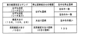
第1特別図柄表示器8aまたは第2特別図柄表示器8bおよび演出表示装置9にはずれ図柄が停止表示される場合には、演出図柄の可変表示が開始されてから、演出図柄の可変表示状態がリーチ状態にならずに、リーチにならない所定の演出図柄の組み合わせが停止表示されることがある。このような演出図柄の可変表示態様を、可変表示結果がはずれ図柄になる場合における「非リーチ」(「通常はずれ」ともいう)の可変表示態様という。
When the shifted symbol is stopped and displayed on the first
第1特別図柄表示器8aまたは第2特別図柄表示器8bおよび演出表示装置9にはずれ図柄が停止表示される場合には、演出図柄の可変表示が開始されてから、演出図柄の可変表示状態がリーチ状態となった後にリーチ演出が実行され、最終的に大当り図柄とはならない所定の演出図柄の組み合わせが停止表示されることがある。このような演出図柄の可変表示結果を、可変表示結果が「はずれ」となる場合における「リーチ」(「リーチはずれ」ともいう)の可変表示態様という。
When the shifted symbol is stopped and displayed on the first
この実施の形態では、第1特別図柄表示器8aまたは第2特別図柄表示器8bに大当り図柄が停止表示される場合には、演出図柄の可変表示状態がリーチ状態になった後にリーチ演出が実行され、最終的に演出表示装置9における「左」、「中」、「右」の各図柄表示エリア9L、9C、9Rに、演出図柄が揃って停止表示される(ただし、突然確変大当りの場合には、リーチとはならずに突然確変大当り図柄(例えば「135」)が停止表示される場合もある)。
In this embodiment, when the big win symbol is stopped and displayed on the first
第1特別図柄表示器8aまたは第2特別図柄表示器8bに小当りである「5」が停止表示される場合には、演出表示装置9において、演出図柄の可変表示態様が「突然確変大当り」である場合と同様に演出図柄の可変表示が行われた後、所定の小当り図柄(突然確変大当り図柄と同じ図柄。例えば「135」)が停止表示されることがある。第1特別図柄表示器8aまたは第2特別図柄表示器8bに小当り図柄である「5」が停止表示されることに対応する演出表示装置9における表示演出を「小当り」の可変表示態様という。
When “5”, which is a small hit, is stopped and displayed on the first
ここで、小当りとは、大当りと比較して大入賞口の開放回数が少ない回数(この実施の形態では0.1秒間の開放を2回)まで許容される当りである。なお、小当り遊技が終了した場合、遊技状態は変化しない。すなわち、確変状態から通常状態に移行したり通常状態から確変状態に移行したりすることはない。また、突然確変大当りとは、大当り遊技状態において大入賞口の開放回数が少ない回数(この実施の形態では0.1秒間の開放を2回)まで許容されるが大入賞口の開放時間が極めて短い大当りであり、かつ、大当り遊技後の遊技状態を確変状態に移行させるような大当りである(すなわち、そのようにすることにより、遊技者に対して突然に確変状態となったかのように見せるものである)。つまり、この実施の形態では、突然確変大当りと小当りとは、大入賞口の開放パターンが同じである。そのように制御することによって、大入賞口の0.1秒間の開放が2回行われると、突然確変大当りであるか小当りであるかまでは認識できないので、遊技者に対して高確率状態(確変状態)を期待させることができ、遊技の興趣を向上させることができる。 Here, the small win is a hit that is allowed up to a small number of times that the big winning opening is opened compared to the big win (in this embodiment, the opening for 0.1 second is twice). When the small hit game ends, the game state does not change. That is, there is no transition from the probability variation state to the normal state or from the normal state to the certain variation state. In addition, the sudden probability change big hit is allowed up to a small number of times of opening of the big prize opening in the big hit gaming state (in this embodiment, the opening for 0.1 second is twice), but the opening time of the big prize opening is extremely large. It is a big hit that is a short jackpot and the game state after the big hit game is shifted to a probable state (that is, by doing so, it appears to the player as if it suddenly became a probable state) Is). In other words, in this embodiment, the sudden winning odds and the small wins have the same opening pattern of the big prize opening. By controlling in such a way, if the winning opening is opened twice for 0.1 seconds, it is impossible to recognize whether it is suddenly a big hit or a small hit, so a high probability state for the player (Probable change state) can be expected, and the interest of the game can be improved.
なお、この実施の形態で示すように大当り種別が全て確変大当り(この実施の形態では、15R確変大当り、10R確変大当り、2R確変大当り、突然確変大当り)であるように構成する場合、小当りを設けなくてもよい。また、大当り種別が全て確変大当りである場合に小当りを設けるように構成する場合には、高確率状態に移行されるのみで高ベース状態を伴わない突然確変大当りを設けるようにすることが好ましい。ただし、この実施の形態では、後述するように、大当り遊技終了後71回目の変動表示の際に高確率/低ベース状態とするときにスーパーリーチとなる割合を高めているのであるが、このように高確率/低ベース状態となる突然確変大当りを設けるように構成する場合には、突然確変大当りによる大当り遊技を終了した後、71回転目の変動表示を終了するまで全ての変動表示において高確率/低ベース状態に制御された状態となるので、確変状態を終了するまでの全ての変動表示においてスーパーリーチとなる割合が高くなってしまう。従って、高確率/低ベース状態となる突然確変大当りを設けるように構成する場合には、高確率/低ベース状態であるときにスーパーリーチとなる割合を必ず毎回高めるのではなく、スーパーリーチとなる割合を高めるときと高めない(通常の割合のまま)ときとを設けるようにしてもよい。また、例えば、遊技状態(例えば、高確率フラグや高ベースフラグがセットされているか否か)を見るのではなく、大当り遊技後の変動表示の回数をカウントし、71回目の変動表示となったときにのみ、スーパーリーチとなる割合を高めるようにしてもよい。そのように構成すれば、高確率/低ベース状態となる突然確変大当りを設けた場合に、突然確変大当りによる大当り遊技を終了した後、確変状態を終了するまでの毎回の変動表示においてスーパーリーチの出現率が連続して高くなってしまう状態を防止することができる。 As shown in this embodiment, when the big hit types are all probability variation big hits (in this embodiment, 15R probability variation big hit, 10R probability variation big hit, 2R probability variation big hit, sudden probability variation big hit), It does not have to be provided. In addition, when the big hit types are all probabilistic big hits, it is preferable to provide a sudden probable big hit that does not involve the high base state only by shifting to the high probability state. . However, in this embodiment, as will be described later, the ratio of the super reach when the high probability / low base state is set at the time of the 71st variation display after the end of the big hit game is increased. In the case of providing a sudden probability variation jackpot with a high probability / low base state, the probability of all variations display is high until the variation display for the 71st rotation is terminated after the jackpot game with the sudden probability variation jackpot is terminated. / Because it is in the state controlled to the low base state, the ratio of super reach becomes high in all the change displays until the probability variation state ends. Therefore, in the case of providing a sudden probability variation big hit that becomes a high probability / low base state, the ratio of the super reach in the high probability / low base state is not necessarily increased every time, but the super reach is achieved. You may make it provide the time of raising a ratio, and the time of not raising (it is a normal ratio). In addition, for example, instead of looking at the gaming state (for example, whether or not a high probability flag or a high base flag is set), the number of variable displays after the big hit game is counted, and the 71st variable display is obtained. Only occasionally you may increase the percentage of superreach. With such a configuration, when a sudden probability change big hit that becomes a high probability / low base state is provided, after the big hit game by the sudden probability change big hit is finished, the super reach of each time the change display until the probability change state ends It is possible to prevent a state in which the appearance rate is continuously increased.
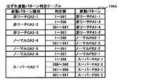
図15は、あらかじめ用意された演出図柄の変動パターンを示す説明図である。図15に示すように、この実施の形態では、可変表示結果が「はずれ」であり演出図柄の可変表示態様が「非リーチ」である場合に対応した変動パターンとして、非リーチPA1−1〜非リーチPA1−4の変動パターンが用意されている。また、可変表示結果が「はずれ」であり演出図柄の可変表示態様が「リーチ」である場合に対応した変動パターンとして、ノーマルPA2−1〜ノーマルPA2−2、ノーマルPB2−1〜ノーマルPB2−2、スーパーPA3−1〜スーパーPA3−2、スーパーPB3−1〜スーパーPB3−2の変動パターンが用意されている。なお、図15に示すように、リーチしない場合に使用され擬似連の演出を伴う非リーチPA1−4の変動パターンについては、再変動が1回行われる。リーチする場合に使用され擬似連の演出を伴う変動パターンのうち、ノーマルPB2−1を用いる場合には、再変動が1回行われる。また、リーチする場合に使用され擬似連の演出を伴う変動パターンのうち、ノーマルPB2−2を用いる場合には、再変動が2回行われる。さらに、リーチする場合に使用され擬似連の演出を伴う変動パターンのうち、スーパーPA3−1〜スーパーPA3−2を用いる場合には、再変動が3回行われる。なお、再変動とは、演出図柄の可変表示が開始されてから表示結果が導出表示されるまでに一旦はずれとなる演出図柄を仮停止させた後に演出図柄の可変表示を再度実行することである。 FIG. 15 is an explanatory diagram showing a variation pattern of the effect symbol prepared in advance. As shown in FIG. 15, in this embodiment, the non-reach PA 1-1 to the non-reach are used as the variation patterns corresponding to the case where the variable display result is “out of” and the variable display mode of the effect symbol is “non-reach”. A variation pattern of reach PA1-4 is prepared. Further, normal PA2-1 to normal PA2-2, normal PB2-1 to normal PB2-2 are variations patterns corresponding to the case where the variable display result is “out of” and the variable display mode of the effect symbol is “reach”. Fluctuation patterns of Super PA3-1 to Super PA3-2 and Super PB3-1 to Super PB3-2 are prepared. Note that, as shown in FIG. 15, re-variation is performed once for the variation pattern of the non-reach PA 1-4 that is used when the reach is not performed and is accompanied by a pseudo-ream effect. Of the variation patterns used for reaching and accompanied by pseudo-rendition, when normal PB2-1 is used, re-variation is performed once. Of the variation patterns that are used for reaching and have a pseudo-continuous effect, when normal PB2-2 is used, re-variation is performed twice. Furthermore, re-variation is performed three times when using the super PA 3-1 to the super PA 3-2 among the variation patterns that are used for reaching and have the effect of pseudo-continuous. Note that the re-variation means that the variable display of the effect symbol is executed again after temporarily stopping the effect symbol that is once deviated from the start of the variable display of the effect symbol until the display result is derived and displayed. .
また、図15に示すように、この実施の形態では、特別図柄の可変表示結果が大当り図柄または小当り図柄になる場合に対応した変動パターンとして、ノーマルPA2−3〜ノーマルPA2−4、ノーマルPB2−3〜ノーマルPB2−4、スーパーPA3−3〜スーパーPA3−4、スーパーPB3−3〜スーパーPB3−4、特殊PG1−1〜特殊PG1−3、特殊PG2−1〜特殊PG2−2の変動パターンが用意されている。なお、図15において、特殊PG1−1〜特殊PG1−3、特殊PG2−1〜特殊PG2−2の変動パターンは、突然確変大当りまたは小当りとなる場合に使用される変動パターンである。また、図15に示すように、突然確変大当りまたは小当りでない場合に使用され擬似連の演出を伴う変動パターンのうち、ノーマルPB2−3を用いる場合には、再変動が1回行われる。また、リーチする場合に使用され擬似連の演出を伴う変動パターンのうち、ノーマルPB2−4を用いる場合には、再変動が2回行われる。さらに、リーチする場合に使用され擬似連の演出を伴う変動パターンのうち、スーパーPA3−3〜スーパーPA3−4を用いる場合には、再変動が3回行われる。また、突然確変大当りまたは小当りの場合に使用され擬似連の演出を伴う特殊PG1−3の変動パターンについては、再変動が1回行われる。 Further, as shown in FIG. 15, in this embodiment, normal PA2-3 to normal PA2-4, normal PB2 are used as variation patterns corresponding to the case where the variable symbol display result of the special symbol is a big hit symbol or a small hit symbol. -3 to Normal PB2-4, Super PA3-3 to SuperPA3-4, Super PB3-3 to Super PB3-4, Special PG1-1 to Special PG1-3, Special PG2-1 to Special PG2-2 Is prepared. In FIG. 15, the fluctuation patterns of special PG1-1 to special PG1-3 and special PG2-1 to special PG2-2 are fluctuation patterns used when sudden probability big hit or small hit. Further, as shown in FIG. 15, the re-variation is performed once when the normal PB2-3 is used among the variation patterns which are used when sudden sudden change is not big hit or small hit and which has a pseudo-continuous effect. Of the fluctuation patterns used for reaching and accompanied by pseudo-continuous effects, when normal PB2-4 is used, re-variation is performed twice. Furthermore, when using super PA3-3 to super PA3-4 among the fluctuation patterns that are used for reaching and have the effect of pseudo-ream, re-variation is performed three times. In addition, for the variation pattern of the special PG 1-3 that is used in the case of sudden probability big hit or small hit and has a pseudo-continuous effect, re-variation is performed once.
なお、この実施の形態では、図15に示すように、リーチの種類に応じて変動時間が固定的に定められている場合(例えば、擬似連ありのスーパーリーチAの場合には変動時間が32.75秒で固定であり、擬似連なしのスーパーリーチAの場合には変動時間が22.75秒で固定である)を示しているが、例えば、同じ種類のスーパーリーチの場合であっても、合算保留記憶数に応じて、変動時間を異ならせるようにしてもよい。例えば、同じ種類のスーパーリーチを伴う場合であっても、合算保留記憶数が多くなるに従って、変動時間が短くなるようにしてもよい。また、例えば、同じ種類のスーパーリーチの場合であっても、第1特別図柄の変動表示を行う場合には、第1保留記憶数に応じて、変動時間を異ならせるようにしてもよく、第2特別図柄の変動表示を行う場合には、第2保留記憶数に応じて、変動時間を異ならせるようにしてもよい。この場合、第1保留記憶数や第2保留記憶数の値ごとに別々の判定テーブルを用意しておき(例えば、保留記憶数0〜2用の変動パターン種別判定テーブルと保留記憶数3,4用の変動パターン種別判定テーブルとを用意しておき)、第1保留記憶数または第2保留記憶数の値に応じて判定テーブルを選択して、変動時間を異ならせるようにしてもよい。
In this embodiment, as shown in FIG. 15, when the variation time is fixedly determined according to the type of reach (for example, the variation time is 32 in the case of Super Reach A with pseudo-ream). In the case of Super Reach A without pseudo-ream, the fluctuation time is fixed at 22.75 seconds). For example, even in the case of the same type of Super Reach Depending on the total number of pending storage, the variation time may be varied. For example, even with the same type of super reach, the variation time may be shortened as the total number of pending storage increases. Also, for example, even in the case of the same type of super reach, when the variable display of the first special symbol is performed, the variable time may be varied according to the first reserved memory number. When the variable display of the two special symbols is performed, the variable time may be varied according to the second reserved memory number. In this case, a separate determination table is prepared for each value of the first reserved memory number and the second reserved memory number (for example, the variation pattern type determination table for the
図16は、各乱数を示す説明図である。各乱数は、以下のように使用される。
(1)ランダム1(MR1):大当りの種類(後述する15R確変大当り、10R確変大当り、2R確変大当り、突然確変大当り)を決定する(大当り種別判定用)
(2)ランダム2(MR2):変動パターンの種類(種別)を決定する(変動パターン種別判定用)
(3)ランダム3(MR3):変動パターン(変動時間)を決定する(変動パターン判定用)
(4)ランダム4(MR4):普通図柄にもとづく当りを発生させるか否か決定する(普通図柄当り判定用)
(5)ランダム5(MR5):ランダム4の初期値を決定する(ランダム4初期値決定用)
FIG. 16 is an explanatory diagram showing each random number. Each random number is used as follows.
(1) Random 1 (MR1): Determines the type of jackpot (15R probability variation big hit, 10R probability variation big hit, 2R probability variation big hit, sudden probability variation big hit, which will be described later) (for jackpot type determination)
(2) Random 2 (MR2): The type (type) of the variation pattern is determined (for variation pattern type determination)
(3) Random 3 (MR3): A variation pattern (variation time) is determined (for variation pattern determination)
(4) Random 4 (MR4): Determines whether or not to generate a hit based on a normal symbol (for normal symbol hit determination)
(5) Random 5 (MR5): Determine the initial value of random 4 (for determining the initial value of random 4)
なお、この実施の形態では、変動パターンは、まず、変動パターン種別判定用乱数(ランダム2)を用いて変動パターン種別を決定し、変動パターン判定用乱数(ランダム3)を用いて、決定した変動パターン種別に含まれるいずれかの変動パターンに決定する。そのように、この実施の形態では、2段階の抽選処理によって変動パターンが決定される。 In this embodiment, the variation pattern is first determined using the variation pattern type determination random number (random 2), and then the variation pattern determined using the variation pattern determination random number (random 3). One of the variation patterns included in the pattern type is determined. Thus, in this embodiment, the variation pattern is determined by a two-stage lottery process.
なお、変動パターン種別とは、複数の変動パターンをその変動態様の特徴に従ってグループ化したものである。例えば、複数の変動パターンをリーチの種類でグループ化して、ノーマルリーチを伴う変動パターンを含む変動パターン種別と、スーパーリーチAを伴う変動パターンを含む変動パターン種別と、スーパーリーチBを伴う変動パターンを含む変動パターン種別とに分けてもよい。また、例えば、複数の変動パターンを擬似連の再変動の回数でグループ化して、擬似連を伴わない変動パターンを含む変動パターン種別と、再変動1回の変動パターンを含む変動パターン種別と、再変動2回の変動パターンを含む変動パターン種別と、再変動3回の変動パターンを含む変動パターン種別とに分けてもよい。また、例えば、複数の変動パターンを擬似連や滑り演出などの特定演出の有無でグループ化してもよい。 The variation pattern type is a group of a plurality of variation patterns according to the characteristics of the variation mode. For example, a plurality of variation patterns are grouped by reach type, and include a variation pattern type including a variation pattern with normal reach, a variation pattern type including a variation pattern with super reach A, and a variation pattern with super reach B. It may be divided into variable pattern types. Further, for example, a plurality of variation patterns are grouped by the number of re-variations of pseudo-continuations, a variation pattern type including a variation pattern without pseudo-ream, a variation pattern type including a variation pattern of one re-variation, It may be divided into a variation pattern type including a variation pattern of two variations and a variation pattern type including a variation pattern of three variations. Further, for example, a plurality of variation patterns may be grouped according to the presence / absence of a specific effect such as a pseudo ream or a slip effect.
なお、この実施の形態では、後述するように、15R確変大当り、10R確変大当り、2R確変大当りである場合には、ノーマルリーチのみを伴う変動パターンを含む変動パターン種別であるノーマルCA3−1と、ノーマルリーチおよび擬似連を伴う変動パターンを含む変動パターン種別であるノーマルCA3−2と、スーパーリーチを伴う変動パターン種別であるスーパーCA3−3とに種別分けされている。また、突然確変大当りである場合には、非リーチの変動パターンを含む変動パターン種別である特殊CA4−1と、リーチを伴う変動パターンを含む変動パターン種別である特殊CA4−2とに種別分けされている。また、小当りである場合には、非リーチの変動パターンを含む変動パターン種別である特殊CA4−1に種別分けされている。また、はずれである場合には、リーチも特定演出も伴わない変動パターンを含む変動パターン種別である非リーチCA2−1と、リーチを伴わないが特定演出を伴う変動パターンを含む変動パターン種別である非リーチCA2−2と、リーチも特定演出も伴わない短縮変動の変動パターンを含む変動パターン種別である非リーチCA2−3と、ノーマルリーチのみを伴う変動パターンを含む変動パターン種別であるノーマルCA2−4と、ノーマルリーチおよび再変動2回の擬似連を伴う変動パターンを含む変動パターン種別であるノーマルCA2−5と、ノーマルリーチおよび再変動1回の擬似連を伴う変動パターンを含む変動パターン種別であるノーマルCA2−6と、スーパーリーチを伴う変動パターン種別であるスーパーCA2−7とに種別分けされている。 In this embodiment, as will be described later, in the case of 15R probability variation per unit, 10R probability variation per unit, 2R probability variation per unit, normal CA3-1 which is a variation pattern type including a variation pattern with only normal reach, and normal reach And normal CA3-2, which is a variation pattern type including a variation pattern with pseudo-continuations, and super CA3-3, which is a variation pattern type with super reach. In addition, in the case of sudden probability variation big hit, it is classified into special CA4-1 that is a variation pattern type including a non-reach variation pattern and special CA4-2 that is a variation pattern type including a variation pattern with reach. ing. Further, in the case of small hits, it is classified into special CA4-1 that is a variation pattern type including a non-reach variation pattern. Further, in the case of a deviation, it is a non-reach CA 2-1 that is a variation pattern type including a variation pattern with no reach and a specific effect, and a variation pattern type that includes a change pattern with a specific effect without a reach. Non-reach CA2-2, non-reach CA2-3 which is a variation pattern type including a variation pattern of shortened variation without reach and specific effects, and normal CA2-4 which is a variation pattern type including a variation pattern with only normal reach And normal CA2-5 which is a variation pattern type including a variation pattern with normal reach and two re-variation pseudo-continuations, and normal CA2 which is a variation pattern type including a variation pattern with one normal reach and one re-variation pseudo-continuation -6 and super CA2-7 which is a variation pattern type with super reach Are the type divided into.
図14に示された遊技制御処理におけるステップS23では、遊技制御用マイクロコンピュータ560は、(1)の大当り種別判定用乱数、および(4)の普通図柄当り判定用乱数を生成するためのカウンタのカウントアップ(1加算)を行う。すなわち、それらが判定用乱数であり、それら以外の乱数が表示用乱数(ランダム2、ランダム3)または初期値用乱数(ランダム5)である。なお、遊技効果を高めるために、上記の乱数以外の乱数も用いてもよい。また、この実施の形態では、大当り判定用乱数として、遊技制御用マイクロコンピュータ560に内蔵されたハードウェア(遊技制御用マイクロコンピュータ560の外部のハードウェアでもよい。)が生成する乱数を用いる。なお、大当り判定用乱数として、ハードウェア乱数ではなく、ソフトウェア乱数を用いてもよい。
In step S23 in the game control process shown in FIG. 14, the
図17(A)は、大当り判定テーブルを示す説明図である。大当り判定テーブルとは、ROM54に記憶されているデータの集まりであって、ランダムRと比較される大当り判定値が設定されているテーブルである。大当り判定テーブルには、通常状態(確変状態でない遊技状態)において用いられる通常時大当り判定テーブルと、確変状態において用いられる確変時大当り判定テーブルとがある。通常時大当り判定テーブルには、図17(A)の左欄に記載されている各数値が設定され、確変時大当り判定テーブルには、図17(A)の右欄に記載されている各数値が設定されている。図17(A)に記載されている数値が大当り判定値である。
FIG. 17A is an explanatory diagram showing a jackpot determination table. The jackpot determination table is a collection of data stored in the
なお、この実施の形態では、確変状態には、大当り抽選において大当りと決定される確率を高めた高確率状態に移行されるとともに、高ベース状態にも移行された状態であるある場合と、高確率状態にのみ移行され高ベース状態には移行されていない(低ベース状態である)状態である場合との2つのケースがあるが、いずれのケースの場合であっても、確変状態である場合には確変時大当り判定テーブルが用いられ、それ以外の場合に通常時大当り判定テーブルが用いられる。なお、後述するように、この実施の形態では、大当りとなると、大当り遊技終了後に高確率状態に移行されるとともに高ベース状態に移行される。そして、大当り終了後、変動表示を71回終了するまで確変状態が継続する。ただし、高ベース状態は、大当り終了後、変動表示を70回終了したときに終了して低ベース状態に移行され、高確率状態のみ変動表示を71回終了するまで継続される。従って、この実施の形態では、大当り終了後、70回目の変動表示を終了してから71回目の変動表示を終了するまでの間、高確率状態のみに移行され、高ベース状態には移行されていない(低ベース状態である)確変状態となる場合がある。 In this embodiment, the probability variation state is shifted to a high probability state in which the probability of being determined to be a big hit in the big hit lottery is increased, and also to a high base state, There are two cases: a case where only the probability state is transferred and a state where the high base state is not transferred (ie, the low base state). Is used in the probability variation big hit determination table, and in other cases the normal big hit determination table is used. As will be described later, in this embodiment, when a big hit is made, the game is shifted to a high probability state and a high base state after the big hit game ends. After the big hit, the probability variation state continues until the variation display is terminated 71 times. However, after the big hit, the high base state is ended when the variable display is ended 70 times, and is shifted to the low base state, and only the high probability state is continued until the variable display is ended 71 times. Therefore, in this embodiment, after the big hit, from the end of the 70th fluctuation display to the end of the 71st fluctuation display, only the high probability state is transferred and the high base state is transferred. There may be a certain probability change state (which is a low base state).
図17(B),(C)は、小当り判定テーブルを示す説明図である。小当り判定テーブルとは、ROM54に記憶されているデータの集まりであって、ランダムRと比較される小当り判定値が設定されているテーブルである。小当り判定テーブルには、第1特別図柄の変動表示を行うときに用いられる小当り判定テーブル(第1特別図柄用)と、第2特別図柄の変動表示を行うときに用いられる小当り判定テーブル(第2特別図柄用)とがある。小当り判定テーブル(第1特別図柄用)には、図17(B)に記載されている各数値が設定され、小当り判定テーブル(第2特別図柄用)には、図17(C)に記載されている各数値が設定されている。また、図17(B),(C)に記載されている数値が小当り判定値である。
FIGS. 17B and 17C are explanatory diagrams showing a small hit determination table. The small hit determination table is a collection of data stored in the
なお、第1特別図柄の変動表示を行う場合にのみ小当りと決定するようにし、第2特別図柄の変動表示を行う場合には小当りを設けないようにしてもよい。この場合、図17(C)に示す第2特別図柄用の小当り判定テーブルは設けなくてもよい。この実施の形態では、遊技状態が確変状態に移行されているときには主として第2特別図柄の変動表示が実行される。遊技状態が確変状態に移行されているときにも小当りが発生するようにし、確変となるか否かを煽る演出を行うように構成すると、現在の遊技状態が確変状態であるにもかかわらず却って遊技者に煩わしさを感じさせてしまう。そこで、第2特別図柄の変動表示中は小当りが発生しないように構成すれば、遊技状態が確変状態である場合には小当りが発生しにくくし必要以上に確変に対する煽り演出を行わないようにすることができ、遊技者に煩わしさを感じさせる事態を防止することができる。 Note that it may be determined that a small hit is made only when the variable display of the first special symbol is performed, and the small hit may not be provided when the variable display of the second special symbol is performed. In this case, the small hit determination table for the second special symbol shown in FIG. In this embodiment, when the gaming state is shifted to the probability changing state, the variation display of the second special symbol is mainly executed. Even if the game state is shifted to the probability change state, a small hit will be generated, and if it is configured to produce an effect asking whether or not the probability change will occur, even though the current game state is the probability change state On the contrary, it makes the player feel annoying. Therefore, if it is configured so that the small hit does not occur during the variation display of the second special symbol, if the gaming state is the probability variation state, it is difficult for the small hit to occur and the excessive effect is not given to the probability variation. This can prevent the player from feeling annoyed.
CPU56は、所定の時期に、乱数回路53のカウント値を抽出して抽出値を大当り判定用乱数(ランダムR)の値とするのであるが、大当り判定用乱数値が図17(A)に示すいずれかの大当り判定値に一致すると、特別図柄に関して大当り(後述する15R確変大当り、10R確変大当り、2R確変大当り、突然確変大当り)にすることに決定する。また、大当り判定用乱数値が図17(B),(C)に示すいずれかの小当り判定値に一致すると、特別図柄に関して小当りにすることに決定する。なお、図17(A)に示す「確率」は、大当りになる確率(割合)を示す。また、図17(B),(C)に示す「確率」は、小当りになる確率(割合)を示す。また、大当りにするか否か決定するということは、大当り遊技状態に移行させるか否か決定するということであるが、第1特別図柄表示器8aまたは第2特別図柄表示器8bにおける停止図柄を大当り図柄にするか否か決定するということでもある。また、小当りにするか否か決定するということは、小当り遊技状態に移行させるか否か決定するということであるが、第1特別図柄表示器8aまたは第2特別図柄表示器8bにおける停止図柄を小当り図柄にするか否か決定するということでもある。
The
なお、この実施の形態では、図17(B),(C)に示すように、小当り判定テーブル(第1特別図柄用)を用いる場合には300分の1の割合で小当りと決定されるのに対して、小当り判定テーブル(第2特別図柄)を用いる場合には3000分の1の割合で小当りと決定される場合を説明する。従って、この実施の形態では、第1始動入賞口13に始動入賞して第1特別図柄の変動表示が実行される場合には、第2始動入賞口14に始動入賞して第2特別図柄の変動表示が実行される場合と比較して、「小当り」と決定される割合が高い。
In this embodiment, as shown in FIGS. 17B and 17C, when the small hit determination table (for the first special symbol) is used, the small hit is determined at a ratio of 1/300. On the other hand, when using the small hit determination table (second special symbol), a case where the small hit is determined at a ratio of 1/3000 will be described. Therefore, in this embodiment, when the start winning prize is given to the first
図17(D),(E)は、ROM54に記憶されている大当り種別判定テーブル131a,131bを示す説明図である。このうち、図17(D)は、遊技球が第1始動入賞口13に入賞したことにもとづく保留記憶を用いて(すなわち、第1特別図柄の変動表示が行われるとき)大当り種別を決定する場合の大当り種別判定テーブル(第1特別図柄用)131aである。また、図17(E)は、遊技球が第2始動入賞口14に入賞したことにもとづく保留記憶を用いて(すなわち、第2特別図柄の変動表示が行われるとき)大当り種別を決定する場合の大当り種別判定テーブル(第2特別図柄用)131bである。
FIGS. 17D and 17E are explanatory diagrams showing the jackpot type determination tables 131 a and 131 b stored in the
大当り種別判定テーブル131a,131bは、可変表示結果を大当り図柄にする旨の判定がなされたときに、大当り種別判定用の乱数(ランダム1)にもとづいて、大当りの種別を「15R確変大当り」、「10R確変大当り」、「2R確変大当り」、「突然確変大当り」のうちのいずれかに決定するために参照されるテーブルである。なお、この実施の形態では、図17(D),(E)に示すように、大当り種別判定テーブル131aには「突然確変大当り」に対して8個の判定値が割り当てられている(40分の8の割合で突然確変大当りと決定される)のに対して、大当り種別判定テーブル131bには「突然確変大当り」に対して2個の判定値が割り当てられている(40分の2の割合で突然確変大当りと決定される)場合を説明する。従って、この実施の形態では、第1始動入賞口13に始動入賞して第1特別図柄の変動表示が実行される場合には、第2始動入賞口14に始動入賞して第2特別図柄の変動表示が実行される場合と比較して、「突然確変大当り」と決定される割合が高い。なお、第1特別図柄用の大当り種別判定テーブル131aにのみ「突然確変大当り」を振り分けるようにし、第2特別図柄用の大当り種別判定テーブル131bには「突然確変大当り」の振り分けを行わない(すなわち、第1特別図柄の変動表示を行う場合にのみ、「突然確変大当り」と決定される場合がある)ようにしてもよい。
The jackpot type determination tables 131a and 131b, when it is determined that the variable display result is a jackpot symbol, based on a random number (random 1) for determining the jackpot type, the jackpot type is set to “15R probability variable big hit”, This table is referred to in order to determine any one of “10R probability variation big hit”, “2R probability variation big hit”, and “sudden probability variation big hit”. In this embodiment, as shown in FIGS. 17D and 17E, eight determination values are assigned to the “sudden probability variation big hit” in the big hit type determination table 131a (40 minutes). In the jackpot type determination table 131b, two judgment values are assigned to “sudden probability variation jackpot” (a ratio of 2/40). Will suddenly be determined to be a promising big hit). Therefore, in this embodiment, when the first special symbol variation display is executed by starting the first
なお、この実施の形態では、図17(D),(E)に示すように、所定量の遊技価値を付与する第1特定遊技状態としての突然確変大当りと、該遊技価値よりも多い量の遊技価値を付与する第2特定遊技状態としての15ラウンドの確変大当り「15R確変大当り」、10ラウンドの確変大当り「10R確変大当り」および2ラウンドの確変大当り「2R確変大当り」とに決定する場合があるとともに、第1特別図柄の変動表示が実行される場合に高い割合で第1特定遊技状態とすることに決定する場合を示しているが、付与される遊技価値は、この実施の形態で示したようなラウンド数に限られない。例えば、第1特定遊技状態と比較して、遊技価値として1ラウンドあたりの大入賞口への遊技球の入賞数(カウント数)の許容量を多くした第2特定遊技状態を決定するようにしてもよい。また、例えば、第1特定遊技状態と比較して、遊技価値として大当り中の1回あたりの大入賞口の開放時間を長くした第2特定遊技状態を決定するようにしてもよい。また、例えば、同じ15ラウンドの大当りであっても、1ラウンドあたり大入賞口を1回開放する第1特定遊技状態と、1ラウンドあたり大入賞口を複数回開放する第2特定遊技状態とを用意し、大入賞口の開放回数が実質的に多くなるようにして第2特定遊技状態の遊技価値を高めるようにしてもよい。この場合、例えば、第1特定遊技状態または第2特定遊技状態いずれの場合であっても、大入賞口を15回開放したときに(この場合、第1特定遊技状態の場合には15ラウンド全てを終了し、第2特定遊技状態の場合には未消化のラウンドが残っていることになる)、大当りがさらに継続するか否かを煽るような態様の演出を実行するようにしてもよい。そして、第1特定遊技状態の場合には内部的に15ラウンド全てを終了していることから大当り遊技を終了し、第2特定遊技状態の場合には内部的に未消化のラウンドが残っていることから、大当り遊技が継続する(恰も15回開放の大当りを終了した後にさらにボーナスで大入賞口の開放が追加で始まったような演出)ようにしてもよい。 In this embodiment, as shown in FIGS. 17D and 17E, a sudden probability variation big hit as a first specific gaming state to which a predetermined amount of game value is given and an amount larger than the game value There are cases where 15 rounds of probability variation big hit “15R probability variation big hit”, 10 rounds probability variation big hit “10R probability variation big hit” and 2 rounds probability variation big hit “2R probability variation big hit” as the second specific gaming state to which the game value is given. In addition, there is a case where it is determined that the first specific gaming state is determined at a high rate when the variable display of the first special symbol is executed, but the game value to be given is shown in this embodiment. The number of rounds is not limited. For example, as compared with the first specific gaming state, the second specific gaming state in which the allowable amount of the winning number (count number) of game balls to the big winning opening per round is increased as the gaming value is determined. Also good. Further, for example, as compared with the first specific gaming state, the second specific gaming state in which the opening time of the big winning opening per game during the big hit may be determined as the gaming value. In addition, for example, even if the same 15 round big hits, the first specific gaming state that opens the big winning opening once per round and the second specific gaming state that opens the big winning opening multiple times per round It may be prepared to increase the gaming value of the second specific gaming state by substantially increasing the number of times the special winning opening is opened. In this case, for example, in any case of the first specific gaming state or the second specific gaming state, when the big winning opening is opened 15 times (in this case, all 15 rounds in the case of the first specific gaming state) In the case of the second specific gaming state, there is an undigested round remaining), and it is possible to execute an effect in such a manner as to inquire whether or not the jackpot continues further. And in the case of the first specific gaming state, all the 15 rounds have been finished internally, so the big hit game is finished, and in the case of the second specific gaming state, there remains an undigested round internally. For this reason, the jackpot game may be continued (the effect that the bonus winning opening is additionally started with a bonus after finishing the bonus hit of 15 times).
この実施の形態では、図17(D),(E)に示すように、大当り種別として、「15R確変大当り」、「10R確変大当り」、「2R確変大当り」および「突然確変大当り」がある。なお、この実施の形態では、大当り遊技において実行されるラウンド数が15ラウンド、10ラウンドおよび2ラウンドの3種類である場合を示しているが、大当り遊技において実行されるラウンド数は、この実施の形態で示したものに限られない。例えば、7ラウンドの大当り遊技に制御する7R確変大当りや、5ラウンドの大当り遊技に制御する5R確変大当りが設けられていてもよい。また、この実施の形態では、大当り種別が「15R確変大当り」、「10R確変大当り」、「2R確変大当り」および「突然確変大当り」の4種類である場合を示しているが、4種類にかぎらず、例えば、5種類以上の大当り種別を設けるようにしてもよい。また、逆に、大当り種別が4種類よりも少なくてもよく、例えば、大当り種別として2種類のみ設けられていてもよい。 In this embodiment, as shown in FIGS. 17D and 17E, the types of big hits include “15R probability variation big hit”, “10R probability variation big hit”, “2R probability variation big hit”, and “sudden probability variation big hit”. In this embodiment, the case where the number of rounds executed in the jackpot game is three types of 15 rounds, 10 rounds, and 2 rounds, but the number of rounds executed in the jackpot game is the number of rounds executed in this implementation. It is not limited to those shown in the form. For example, a 7R probability variable jackpot that is controlled for a 7-round jackpot game and a 5R probability variable jackpot that is controlled for a 5-round jackpot game may be provided. In this embodiment, there are four types of jackpot types: “15R probability variation jackpot”, “10R probability variation jackpot”, “2R probability variation jackpot”, and “sudden probability variation jackpot”. Instead, for example, five or more types of jackpot types may be provided. Conversely, the jackpot type may be less than four types, for example, only two types of jackpot types may be provided.
「15R確変大当り」とは、15ラウンドの大当り遊技状態に制御し、その大当り遊技状態の終了後に確変状態に移行させる大当りである(この実施の形態では、高確率状態に移行されるとともに高ベース状態にも移行される。後述するステップS166〜S169参照)。そして、確変状態に移行した後、変動表示を70回終了すると高ベース状態が終了し(ステップS169,S144参照)、変動表示を71回終了すると高確率状態が終了する(ステップS167,S140参照)。 The “15R probability variable big hit” is a big hit that is controlled to a 15-round big hit gaming state, and shifts to the probable change state after the big hit gaming state is finished (in this embodiment, the high probability state and the high The state is also shifted to (see steps S166 to S169 described later). After the transition to the probability variation state, the high base state ends when the fluctuation display ends 70 times (see steps S169 and S144), and the high probability state ends when the fluctuation display ends 71 times (see steps S167 and S140). .
「10R確変大当り」とは、10ラウンドの大当り遊技状態に制御し、その大当り遊技状態の終了後に確変状態に移行させる大当りである(この実施の形態では、高確率状態に移行されるとともに高ベース状態にも移行される。後述するステップS166〜S169参照)。そして、確変状態に移行した後、変動表示を70回終了すると高ベース状態が終了し(ステップS169,S144参照)、変動表示を71回終了すると高確率状態が終了する(ステップS167,S140参照)。 The “10R probability variable big hit” is a big hit that is controlled to a 10-round big hit gaming state and shifts to the probability changed state after the big hit gaming state ends (in this embodiment, the high probability state and the high The state is also shifted to (see steps S166 to S169 described later). After the transition to the probability variation state, the high base state ends when the fluctuation display ends 70 times (see steps S169 and S144), and the high probability state ends when the fluctuation display ends 71 times (see steps S167 and S140). .
「2R確変大当り」とは、2ラウンドの大当り遊技状態に制御し、その大当り遊技状態の終了後に確変状態に移行させる大当りである(この実施の形態では、高確率状態に移行されるとともに高ベース状態にも移行される。後述するステップS166〜S169参照)。そして、確変状態に移行した後、変動表示を70回終了すると高ベース状態が終了し(ステップS169,S144参照)、変動表示を71回終了すると高確率状態が終了する(ステップS167,S140参照)。 The “2R probability variable big hit” is a big hit that is controlled to a two-round big hit gaming state and shifts to the probability changed state after the big hit gaming state is finished (in this embodiment, the high probability state and the high base The state is also shifted to (see steps S166 to S169 described later). After the transition to the probability variation state, the high base state ends when the fluctuation display ends 70 times (see steps S169 and S144), and the high probability state ends when the fluctuation display ends 71 times (see steps S167 and S140). .
なお、「2R確変大当り」は、後述する「突然確変大当り」と同様に大入賞口の開放回数が2回(2ラウンド)のみ許容される大当りであるが、「突然確変大当り」と異なり、1ラウンドあたりの大入賞口の開放時間が長い(この実施の形態では29秒)。従って、後述する「突然確変大当り」の場合には、大当り遊技中に遊技球が大入賞口に入賞することは殆ど期待できないのであるが、「2R確変大当り」となった場合には、大入賞口の開放回数は少ないものの大当り遊技中に遊技球が大入賞口に入賞することを期待することができる。 The “2R probability variation big hit” is a big hit that allows only two (2 rounds) opening of the big prize opening as in the case of “sudden probability variation big hit” described later. The opening time of the big prize opening per round is long (29 seconds in this embodiment). Therefore, in the case of “suddenly promising big hit”, which will be described later, it is almost impossible to expect the game ball to win the big winning opening during the big hit game, but in the case of “2R probable big hit”, the big winning Although the number of times the mouth is opened is small, it can be expected that the game ball will win the big prize mouth during the big hit game.
また、「突然確変大当り」とは、「15R確変大当り」や「10R確変大当り」と比較して大入賞口の開放回数が少ない回数(この実施の形態では0.1秒間の開放を2回)まで許容される大当りである。すなわち、「突然確変大当り」となった場合には、2ラウンドの大当り遊技状態に制御される。また、「15R確変大当り」や、「10R確変大当り」、「2R確変大当り」では、1ラウンドあたりの大入賞口の開放時間が29秒と長いのに対して、「突然確変大当り」では1ラウンドあたりの大入賞口の開放時間が0.1秒と極めて短く、大当り遊技中に大入賞口に遊技球が入賞することは殆ど期待できない。そして、この実施の形態では、その突然確変大当り遊技状態の終了後に確変状態に移行される(この実施の形態では、高確率状態に移行されるとともに高ベース状態にも移行される。後述するステップS166〜S169参照)。そして、確変状態に移行した後、変動表示を70回終了すると高ベース状態が終了し(ステップS169,S144参照)、変動表示を71回終了すると高確率状態が終了する(ステップS167,S140参照)。 The “sudden probability change big hit” is the number of times that the big winning opening is less than “15R probability change big hit” or “10R probability change big hit” (in this embodiment, the opening for 0.1 second is twice). The jackpot allowed up to. In other words, when “suddenly promising big hit”, the game is controlled to a two round big hit gaming state. In addition, “15R probability variation big hit”, “10R probability variation big hit”, and “2R probability variation big hit” have a long opening time of 29 seconds per round, whereas “sudden probability variation big hit” takes one round. The opening time of the winning jackpot is as short as 0.1 seconds, and it is almost impossible to expect a game ball to win a winning prize during the big hit game. In this embodiment, after the sudden probability change big hit gaming state is finished, the state is changed to the probability change state (in this embodiment, the state is changed to the high probability state and is also changed to the high base state. (See S166 to S169). After the transition to the probability variation state, the high base state ends when the fluctuation display ends 70 times (see steps S169 and S144), and the high probability state ends when the fluctuation display ends 71 times (see steps S167 and S140). .
なお、前述したように、この実施の形態では、「小当り」となった場合にも、大入賞口の開放が0.1秒間ずつ2回行われ、「突然確変大当り」による大当り遊技状態と同様の制御が行われる。そして、「小当り」となった場合には、大入賞口の2回の開放が終了した後、遊技状態は変化せず、「小当り」となる前の遊技状態が維持される。そのようにすることによって、「突然確変大当り」であるか「小当り」であるかを認識できないようにし、遊技の興趣を向上させている。なお、この実施の形態で示すように大当り種別が全て確変大当り(この実施の形態では、15R確変大当り、10R確変大当り、2R確変大当り、突然確変大当り)であるように構成する場合、小当りを設けなくてもよい。また、この実施の形態のように大当り種別が全て確変大当りである場合に小当りを設けるように構成する場合には、高確率状態に移行されるのみで高ベース状態を伴わない突然確変大当りを設けるようにすること(大入賞口の開放パターンも突然確変大当りと小当りの場合とで同じにすること)が好ましい。ただし、この実施の形態では、後述するように、大当り遊技終了後71回目の変動表示を実行するときにスーパーリーチとなる割合を高めているのであるが、小当りおよび高ベース状態を伴わない突然確変大当りを設けるように構成する場合には、71回目の変動表示においてスーパーリーチとなる割合を必ず毎回高めるのではなく、スーパーリーチとなる割合を高めるときと高めない(通常の割合のまま)ときとを設けるようにし、突然確変大当り後の高確率状態において低確率/低ベース状態のときと同じ選択割合/選択方法で変動パターンを選択するように構成すればよい。そのように構成すれば、大当り終了後71回目の変動表示でスーパーリーチの出現率が永久的に高くなってしまう状態を防止することができる。 As described above, in this embodiment, even in the case of “small hit”, the big winning opening is opened twice for 0.1 seconds, and the big hit gaming state by “suddenly probable big hit” Similar control is performed. In the case of “small hit”, the game state does not change after the opening of the big winning opening twice, and the game state before “small hit” is maintained. By doing so, it is made impossible to recognize whether it is “suddenly promising big hit” or “small hit”, and the interest of the game is improved. As shown in this embodiment, when the big hit types are all probability variation big hits (in this embodiment, 15R probability variation big hit, 10R probability variation big hit, 2R probability variation big hit, sudden probability variation big hit), It does not have to be provided. In addition, when the big hit types are all probabilistic big hits as in this embodiment, when a small hit is provided, only sudden transition with high base state without high base state is performed. It is preferable to provide it (the opening pattern of the big prize opening is also the same for the case of sudden probability change big hit and small hit). However, in this embodiment, as will be described later, the ratio of becoming super reach when executing the 71st fluctuation display after the end of the big hit game is increased. When it is configured to provide a probable big hit, when the ratio of super reach is not necessarily increased every time in the 71st fluctuation display, but when the ratio of super reach is increased or not increased (the normal ratio is maintained) And a variation pattern may be selected with the same selection ratio / selection method as in the low probability / low base state in the high probability state after suddenly probable big hit. With such a configuration, it is possible to prevent a state in which the appearance rate of super reach becomes permanently high in the 71st variation display after the end of the big hit.
大当り種別判定テーブル131a,131bには、ランダム1の値と比較される数値であって、「15R確変大当り」、「10R確変大当り」、「2R確変大当り」、「突然確変大当り」のそれぞれに対応した判定値(大当り種別判定値)が設定されている。CPU56は、ランダム1の値が大当り種別判定値のいずれかに一致した場合に、大当りの種別を、一致した大当り種別判定値に対応する種別に決定する。
The big hit type determination tables 131a and 131b are numerical values that are compared with a random 1 value and correspond to "15R probability variation big hit", "10R probability variation big hit", "2R probability variation big hit", and "sudden probability variation big hit", respectively. Judgment value (big hit type judgment value) is set. When the value of random 1 matches any of the jackpot type determination values, the
図18(A)〜(C)は、大当り用変動パターン種別判定テーブル132A〜132Cを示す説明図である。大当り用変動パターン種別判定テーブル132A〜132Cは、可変表示結果を大当り図柄にする旨の判定がなされたときに、大当り種別の判定結果に応じて、変動パターン種別を、変動パターン種別判定用の乱数(ランダム2)にもとづいて複数種類のうちのいずれかに決定するために参照されるテーブルである。 18A to 18C are explanatory diagrams showing the big hit variation pattern type determination tables 132A to 132C. The jackpot variation pattern type determination tables 132A to 132C, when it is determined that the variable display result is a jackpot symbol, the variation pattern type is determined according to the determination result of the jackpot type, and a random number for determining the variation pattern type. It is a table that is referred to in order to determine one of a plurality of types based on (Random 2).
各大当り用変動パターン種別判定テーブル132A〜132Cには、変動パターン種別判定用の乱数(ランダム2)の値と比較される数値(判定値)であって、ノーマルCA3−1〜ノーマルCA3−2、スーパーCA3−3、特殊CA4−1、特殊CA4−2の変動パターン種別のいずれかに対応する判定値が設定されている。 Each of the big hit variation pattern type determination tables 132A to 132C includes numerical values (determination values) to be compared with random number (random 2) values for variation pattern type determination, which are normal CA3-1 to normal CA3-2, A determination value corresponding to any one of the variation pattern types of super CA3-3, special CA4-1, and special CA4-2 is set.
例えば、大当り種別が「10R確変大当り」や「2R確変大当り」である場合に用いられる図18(A)に示す大当り用変動パターン種別判定テーブル132Aと、大当り種別が「15R確変大当り」である場合に用いられる図18(B)に示す大当り用変動パターン種別判定テーブル132Bとで、ノーマルCA3−1〜ノーマルCA3−2、スーパーCA3−3の変動パターン種別に対する判定値の割り当てが異なっている。 For example, the big hit variation pattern type determination table 132A shown in FIG. 18A used when the big hit type is “10R probability variation big hit” or “2R probability variation big hit”, and when the big hit type is “15R probability variation big hit”. 18B is different from the big hit variation pattern type determination table 132B shown in FIG. 18B in the assignment of determination values to the variation pattern types of normal CA3-1 to normal CA3-2 and super CA3-3.
このように、大当り種別に応じて選択される大当り用変動パターン種別判定テーブル132A〜132Cを比較すると、大当り種別に応じて各変動パターン種別に対する判定値の割り当てが異なっている。また、大当り種別に応じて異なる変動パターン種別に対して判定値が割り当てられている。よって、大当り種別を複数種類のうちのいずれにするかの決定結果に応じて、異なる変動パターン種別に決定することができ、同一の変動パターン種別に決定される割合を異ならせることができる。 As described above, when the big hit variation pattern type determination tables 132A to 132C selected according to the big hit type are compared, the assignment of the determination value to each fluctuation pattern type is different according to the big hit type. Also, determination values are assigned to different variation pattern types depending on the jackpot type. Therefore, different variation pattern types can be determined according to the determination result of whether the big hit type is a plurality of types, and the ratio determined for the same variation pattern type can be varied.
なお、図18(A),(B)に示すように、この実施の形態では、「15R確変大当り」、「10R確変大当り」または「2R確変大当り」である場合には、変動パターン種別判定用の乱数(ランダム2)の値が150〜251であれば、少なくともスーパーリーチ(スーパーリーチA、スーパーリーチB)を伴う変動表示が実行されることがわかる。 As shown in FIGS. 18A and 18B, in this embodiment, when “15R probability variation big hit”, “10R probability variation big hit” or “2R probability variation big hit” is used, the variation pattern type determination is performed. If the value of the random number (random 2) is 150 to 251, it can be seen that the variable display with at least super reach (super reach A, super reach B) is executed.
また、スーパーリーチ大当りについて、擬似連を伴う変動パターン種別(スーパーPA3−3、スーパーPA3−4の変動パターンを含む変動パターン種別)と、擬似連を伴わない変動パターン種別(スーパーPB3−3、スーパーPB3−4の変動パターンを含む変動パターン種別)とに分けてもよい。この場合、10R/2R確変大当り用の大当り用変動パターン種別判定テーブル132Aおよび15R確変大当り用の大当り用変動パターン種別判定テーブル132Bの両方において、スーパーリーチかつ擬似連を伴う変動パターン種別と、スーパーリーチかつ擬似連を伴わない変動パターン種別とが割り当てられることになる。 In addition, for the super reach big hit, the variation pattern type with pseudo-continuity (variation pattern type including the variation pattern of Super PA3-3 and Super PA3-4) and the variation pattern type without super-continuity (Super PB3-3, Super It may be divided into a variation pattern type including a variation pattern of PB3-4. In this case, in both the big hit variation pattern type determination table 132A for 10R / 2R probability variation jackpot and the big hit variation pattern type determination table 132B for 15R probability variation big hit, the variation pattern type with super reach and pseudo-ream and super reach In addition, a variation pattern type that does not involve pseudo-continuations is assigned.
また、大当り種別が「突然確変大当り」である場合に用いられる大当り用変動パターン種別判定テーブル132Cでは、例えば、特殊CA4−1、特殊CA4−2といった大当り種別が「突然確変大当り」以外である場合には判定値が割り当てられない変動パターン種別に対して、判定値が割り当てられている。よって、可変表示結果が「大当り」となり大当り種別が「突然確変大当り」となることに応じて突然確変大当り状態に制御する場合には、15R確変大当りや10R確変大当り、2R確変大当りによる大当り状態に制御する場合とは異なる変動パターン種別に決定することができる。 In the big hit variation pattern type determination table 132C used when the big hit type is “suddenly probable big hit”, for example, when the big hit type such as special CA4-1 or special CA4-2 is other than “suddenly probable big hit”. A determination value is assigned to a variation pattern type to which no determination value is assigned. Therefore, when the variable display result is “big hit” and the big hit type is “suddenly probable big hit”, when the control is suddenly probable big hit state, the big hit state with 15R probable big hit, 10R probable big hit or 2R probable big hit The variation pattern type can be determined differently from the case of control.
また、図18(D)は、小当り用変動パターン種別判定テーブル132Dを示す説明図である。小当り用変動パターン種別判定テーブル132Dは、可変表示結果を小当り図柄にする旨の判定がなされたときに、変動パターン種別を、変動パターン種別判定用の乱数(ランダム2)にもとづいて複数種類のうちのいずれかに決定するために参照されるテーブルである。なお、この実施の形態では、図18(D)に示すように、小当りとすることに決定されている場合には、変動パターン種別として特殊CA4−1が決定される場合が示されている。 FIG. 18D is an explanatory diagram showing a small hit variation pattern type determination table 132D. The small hit variation pattern type determination table 132D has a plurality of variation pattern types based on a random number (random 2) for variation pattern type determination when it is determined that the variable display result is a small hit symbol. It is a table that is referred to in order to determine any of the above. In this embodiment, as shown in FIG. 18D, when it is determined to be a small hit, the case where the special CA4-1 is determined as the variation pattern type is shown. .
図19(A)〜(D)は、はずれ用変動パターン種別判定テーブル135A〜135Dを示す説明図である。このうち、図19(A)は、遊技状態が通常状態であるとともに合算保留記憶数が3未満である場合に用いられるはずれ用変動パターン種別判定テーブル135Aを示している。また、図19(B)は、遊技状態が通常状態であるとともに合算保留記憶数が3以上である場合に用いられるはずれ用変動パターン種別判定テーブル135Bを示している。また、図19(C)は、遊技状態が確変状態のうちの高確率/高ベース状態(大当り終了後、70回目の変動表示を終了するまでの状態)である場合に用いられるはずれ用変動パターン種別判定テーブル135Cを示している。また、図19(D)は、遊技状態が確変状態のうちの高確率/低ベース状態(大当り終了後、70回目の変動表示を終了してから71回目の変動表示を終了するまでの状態)である場合に用いられるはずれ用変動パターン種別判定テーブル135Dを示している。はずれ用変動パターン種別判定テーブル135A〜135Dは、可変表示結果をはずれ図柄にする旨の判定がなされたときに、変動パターン種別を、変動パターン種別判定用の乱数(ランダム2)にもとづいて複数種類のうちのいずれかに決定するために参照されるテーブルである。 FIGS. 19A to 19D are explanatory diagrams showing the deviation variation pattern type determination tables 135A to 135D. Among these, FIG. 19A shows the variation pattern type determination table 135A for loss used when the gaming state is the normal state and the total number of pending storages is less than 3. FIG. 19B shows a variation pattern type determination table 135B for loss used when the gaming state is the normal state and the total number of pending storages is 3 or more. FIG. 19C shows a variation pattern for loss used when the gaming state is a high probability / high base state (a state from the end of the big hit until the end of the 70th variation display) in the probability variation state. A type determination table 135C is shown. FIG. 19D shows a high probability / low base state in which the gaming state is in a probabilistic state (the state from the end of the 70th variation display to the end of the 71st variation display after the end of the big hit). Shows a variation pattern type determination table 135D for loss used in the case of The deviation variation pattern type determination tables 135A to 135D have a plurality of variation pattern types based on a random number (random 2) for variation pattern type determination when it is determined that the variable display result is a loss symbol. It is a table that is referred to in order to determine any of the above.
図19(C),(D)に示すように、この実施の形態では、確変状態である場合であっても、大当り終了後、最後の71回目の変動表示が行われる場合には、それ以前の70回目の変動表示が行われる場合までと比較して、スーパーリーチを伴う変動パターンが選択される割合が高い。そのようにすることによって、この実施の形態では、確変状態が終了する最後の変動表示では高い確率でスーパーリーチの変動表示を行うようにすることによって、確変状態終了時における遊技者の大当りに対する期待感を高めている。なお、最後の71回目の変動表示だけにかぎらず、例えば、確変状態が終了する所定回数前(例えば、5回前)の変動表示から最終回の変動表示にわたってスーパーリーチとなる割合を高めるなど、複数回の変動表示にわたって高い確率でスーパーリーチの変動表示を行うようにしてもよい。 As shown in FIGS. 19C and 19D, in this embodiment, even when the probability variation state is present, if the last 71st variation display is performed after the big hit, the previous time is displayed. Compared to the case where the 70th variation display is performed, the variation pattern with super reach is selected more frequently. By doing so, in this embodiment, the expectation for the big hit of the player at the end of the probability variation state is performed by performing the super reach variation display with a high probability in the last variation display where the probability variation state ends. The feeling is heightened. Not only the last 71th variation display, for example, increasing the ratio of super reach from the variation display of the predetermined number of times before the probability variation state ends (for example, 5 times before) to the last variation display, etc. Super reach variation display may be performed with high probability over a plurality of variation displays.
なお、この実施の形態では、大当り終了後、高確率状態については71回目の変動表示が終了するまで継続するようにし、高ベース状態については70回目の変動表示が終了するまで継続するようにすることによって、確変状態最後の71回目の変動表示においては高確率/低ベース状態に制御されている場合を示しているが、高ベース状態についても71回目の変動表示が終了するまで継続するようににし、確変状態最後の71回目の変動表示においても高確率/高ベース状態に制御されているようにしてもよい。ただし、このように制御すると、この実施の形態では、後述するように、変動パターン設定処理において高確率フラグや高ベースフラグの状態によって、はずれ用変動パターン種別判定テーブル135C,135Dを選択しているのであるが(ステップS95,S96,S100,S101参照)、確変状態最後の71回目の変動表示でも高確率/高ベース状態のままであることから、このようにフラグの状態を確認してはずれ用変動パターン種別判定テーブル135C,135Dを選択することができなくなる。そこで、このように、確変状態最後の71回目の変動表示においても高確率/高ベース状態に制御する場合には、後述する高確率回数カウンタや高ベース回数カウンタの値を確認し、カウンタの値が残り1回となっていれば、はずれ用変動パターン種別判定テーブル135Dを選択するようにし、カウンタの値がまだ2以上であれば、はずれ用変動パターン種別判定テーブル135Cを選択するようにしてもよい。 In this embodiment, after the big hit, the high probability state continues until the 71st variation display ends, and the high base state continues until the 70th variation display ends. Thus, in the 71st variation display in the final probability variation state, the case where the high probability / low base state is controlled is shown, but the high base state is continued until the 71st variation display is completed. In the 71st variation display at the end of the probability variation state, the high probability / high base state may be controlled. However, if controlled in this way, in this embodiment, the variation pattern type determination tables 135C and 135D for detachment are selected according to the state of the high probability flag or the high base flag in the variation pattern setting process, as will be described later. (Refer to Steps S95, S96, S100, and S101). However, since the 71st variation display at the end of the probability variation state remains in the high probability / high base state, the state of the flag is confirmed in this way. It becomes impossible to select the variation pattern type determination tables 135C and 135D. Thus, in the case of controlling to the high probability / high base state even in the 71st variation display in the final probability variation state, the values of the high probability count counter and the high base count counter, which will be described later, are confirmed, and the counter value If the remaining is once, the deviation variation pattern type determination table 135D is selected. If the counter value is still 2 or more, the variation pattern type determination table 135C for deviation is selected. Good.
また、確変状態が終了する所定回数前(例えば、5回前)の変動表示から最終回の変動表示にわたってスーパーリーチとなる割合を高めるように構成する場合、例えば、大当り終了時に後述する高確率回数カウンタや高ベース回数カウンタに75回をセットするようにし(例えば、高確率回数カウンタおよび高ベース回数カウンタの両方に75をセットして、75回の変動表示を終了するまで高確率/高ベース状態が継続するようにしてもよく、高確率回数カウンタに75をセットし、高ベース回数カウンタに70をセットして、確変状態が終了する5変動前から最終回の変動表示までは高確率/低ベース状態に制御するようにしてもよい。なお、確変状態が終了する5変動前から最終回の変動表示までは高確率/低ベース状態に制御する場合には、この実施の形態で示したものと同様の制御に従い、高確率フラグや高ベースフラグを確認することによって、はずれ用変動パターン種別判定テーブル135C,135Dを選択するようにしてもよい(ステップS95,S96,S100,S101参照)。)、変動表示の開始時に、高確率回数カウンタや高ベース回数カウンタの値が残り所定数(例えば5)以内となっているか否か(確変状態の残り回数が所定回数以内となっているか否か)を確認し、所定数(例えば5)以内となっていれば、図19(D)に示すスーパーリーチの割合を高めたはずれ用変動パターン種別判定テーブル135Dを選択するようにし、カウンタの値がまだ所定数(例えば5)より多ければ、図19(C)に示すはずれ用変動パターン種別判定テーブル135Cを選択するようにしてもよい。なお、確変状態が終了する所定回数前(例えば、5回前)の変動表示からスーパーリーチとなる割合を高めるように構成する場合の制御方法は、この実施の形態に示したものにかぎらず、例えば、高確率回数カウンタには、この実施の形態と同様に71をセットし、逆に高ベース回数カウンタに66をセットすることによって、確変状態が終了する5変動前から最終回の変動表示までは高確率/低ベース状態に制御するようにし、高確率回数カウンタの値が残り5以内となっているか否かを確認することによって、はずれ用変動パターン種別判定テーブル135C,135Dを選択するようにしてもよい。また、大当り後の変動回数を高確率回数カウンタや高ベース回数カウンタのカウント値にもとづいて判断するのではなく、他のカウンタを用いて判断するようにしてもよい。例えば、大当り遊技終了後の変動回数をカウントするカウンタを設けるようにし、そのカウンタのカウント値が所定範囲(例えば、71〜75または66〜71。)であるか否かを確認することによって、確変状態が終了する5変動前から最終回の変動表示までの間であるか否かを判定し、はずれ用変動パターン種別判定テーブル135C,135Dを選択するようにしてもよい(なお、確変状態が終了する最終回の変動表示1回のみスーパーリーチの選択割合を高めるように構成する場合にも同様に構成してもよく、例えば、大当り遊技終了後の変動回数をカウントするカウンタの値が例えば71となった場合にはずれ用変動パターン種別判定テーブル135Dを選択するように構成してもよい)。また、確変状態が終了する所定回数前(例えば、5回前)の変動表示から最終回の変動表示が終了するまでを高確率/低ベース状態に制御するように構成する場合には、この実施の形態と同様に、変動パターン設定処理において高確率フラグや高ベースフラグの状態によって、はずれ用変動パターン種別判定テーブル135C,135Dを選択するようにしてもよい(ステップS95,S96,S100,S101参照)。 Further, when the ratio of the super reach is increased from the fluctuation display a predetermined number of times before the probability variation state ends (for example, five times before) to the last fluctuation display, for example, a high probability number described later at the end of the big hit Set the counter and the high base number counter to 75 times (for example, set both the high probability number counter and the high base number counter to 75, and the high probability / high base state until 75 times of variable display is completed. The high probability count counter is set to 75 and the high base count counter is set to 70. From the 5th change before the probability change state ends to the last change display, the high probability / low It is also possible to control to the base state.In the case of controlling to the high probability / low base state from the 5th change before the probability change state ends to the last change display. In this case, according to the same control as that shown in this embodiment, the deviation variation pattern type determination tables 135C and 135D may be selected by checking the high probability flag and the high base flag (step S95, S96, S100, S101))) At the start of the variable display, whether or not the value of the high probability count counter and the high base count counter is within a predetermined number (for example, 5) or not (the remaining number of probability variation states) Is within a predetermined number), and if it is within a predetermined number (for example, 5), the variation pattern type determination table 135D for detachment with an increased super reach ratio shown in FIG. 19D. If the counter value is still greater than a predetermined number (for example, 5), the deviation variation pattern type determination table shown in FIG. It may be selected to 135C. In addition, the control method in the case where it is configured to increase the ratio of the super reach from the fluctuation display a predetermined number of times before the probability variation state ends (for example, five times before) is not limited to that shown in this embodiment. For example, 71 is set in the high probability count counter in the same manner as in this embodiment, and conversely, 66 is set in the high base count counter. Is controlled to a high probability / low base state, and by confirming whether the value of the high probability count counter is within 5 or less, the variation pattern type determination tables 135C and 135D for loss are selected. May be. Further, the number of fluctuations after the big hit may not be determined based on the count value of the high probability number counter or the high base number counter, but may be determined using another counter. For example, a counter that counts the number of fluctuations after the end of the big hit game is provided, and whether the count value of the counter is within a predetermined range (for example, 71 to 75 or 66 to 71) is confirmed. It may be determined whether or not the state is between five changes before the end of the state and the last change display, and the variation pattern type determination tables 135C and 135D for loss may be selected (the probability change state is ended). For example, the configuration may be configured in such a manner that the selection ratio of the super reach is increased only once in the last variation display. For example, the counter value for counting the number of variations after the big hit game is 71, for example, In such a case, the shift variation pattern type determination table 135D may be selected. In addition, when the configuration is such that the high-probability / low-base state is controlled from the change display a predetermined number of times before the probability change state ends (for example, five times before) to the end of the last change display. In the variation pattern setting process, the variation pattern type determination tables 135C and 135D for detachment may be selected according to the state of the high probability flag or the high base flag (see steps S95, S96, S100, and S101). ).
なお、図19に示す例では、遊技状態が高ベース状態である場合と合算保留記憶数が3以上である場合とで別々のはずれ用変動パターン種別判定テーブル135B〜135Dを用いる場合を示しているが、高ベース状態である場合と合算保留記憶数が3以上である場合とで、共通のはずれ用変動パターン種別判定テーブルを用いるように構成してもよい。また、図19(C)に示す例では、合算保留記憶数にかかわらず共通の高ベース用のはずれ用変動パターン種別判定テーブル135Cを用いる場合を示しているが、高ベース用のはずれ用変動パターン種別判定テーブルとして合算保留記憶数に応じた複数のはずれ用変動パターン判定テーブル(判定値の割合を異ならせたテーブル)を用いるようにしてもよい。 In the example shown in FIG. 19, a case where separate variation pattern type determination tables 135 </ b> B to 135 </ b> D are used for the case where the gaming state is the high base state and the case where the total number of pending storages is 3 or more is shown. However, the common deviation variation pattern type determination table may be used in the case of the high base state and in the case where the total number of pending storages is 3 or more. In the example shown in FIG. 19C, the common high base deviation variation pattern type determination table 135C is used regardless of the total number of pending storage, but the high base deviation variation pattern is used. As the type determination table, a plurality of variation pattern determination tables for deviation corresponding to the total number of pending storages (tables with different ratios of determination values) may be used.
なお、この実施の形態では、遊技状態が通常状態である場合には、合算保留記憶数が3未満である場合に用いるはずれ変動パターン種別判定テーブル135Aと、合算保留記憶数が3以上である場合に用いるはずれ変動パターン種別判定テーブル135Bとの2種類のテーブルを用いる場合を示しているが、はずれ変動パターン種別判定テーブルの分け方は、この実施の形態で示したものにかぎられない。例えば、合算保留記憶数の値ごとに別々のはずれ変動パターン種別判定テーブルをそれぞれ備えてもよい(すなわち、合算保留記憶数0個用、合算保留記憶数1個用、合算保留記憶数2個用、合算保留記憶数3個用、合算保留記憶数4個用・・・のはずれ変動パターン種別判定テーブルをそれぞれ別々に用いるようにしてもよい)。また、例えば、合算保留記憶数の他の複数の値の組合せに対応したはずれ変動パターン種別判定テーブルを用いるようにしてもよい。例えば、合算保留記憶数0〜2用、合算保留記憶数3用、合算保留記憶数4用・・・のはずれ変動パターン種別判定テーブルを用いるようにしてもよい。
In this embodiment, when the gaming state is the normal state, the deviation variation pattern type determination table 135A used when the total pending storage number is less than 3 and the total pending storage number is 3 or more. In this example, two types of tables are used, namely, the deviation variation pattern type determination table 135B. However, the method of dividing the variation variation pattern type determination table is not limited to that shown in this embodiment. For example, a separate deviation variation pattern type determination table may be provided for each value of the total pending storage number (that is, for the total
また、この実施の形態では、合算保留記憶数に応じてはずれ変動パターン種別判定テーブルを複数備える場合を示しているが、第1保留記憶数や第2保留記憶数に応じてはずれ変動パターン種別判定テーブルを複数備えるようにしてもよい。例えば、第1特別図柄の変動表示を行う場合には、第1保留記憶数の値ごとに別々に用意されたはずれ変動パターン種別判定テーブルを用いるようにしてもよい(すなわち、第1保留記憶数0個用、第1保留記憶数1個用、第1保留記憶数2個用、第1保留記憶数3個用、第1保留記憶数4個用・・・のはずれ変動パターン種別判定テーブルをそれぞれ別々に用いるようにしてもよい)。また、例えば、第1保留記憶数の他の複数の値の組合せに対応したはずれ変動パターン種別判定テーブルを用いるようにしてもよい。例えば、第1保留記憶数0〜2用、第1保留記憶数3用、第1保留記憶数4用・・・のはずれ変動パターン種別判定テーブルを用いるようにしてもよい。この場合であっても、第1保留記憶数や第2保留記憶数が多い場合(例えば3以上)には、変動時間が短い変動パターンを含む変動パターン種別が選択されやすいように構成すればよい。また、このような場合であっても、特定の可変表示パターンとしてのスーパーリーチを伴う変動パターンを含む変動パターン種別に対して共通の判定値を割り当てるように構成すればよい。
Further, in this embodiment, a case is shown in which a plurality of deviation variation pattern type determination tables are provided according to the total number of reserved storages, but deviation variation pattern type determination is performed according to the first and second reserved memory numbers. A plurality of tables may be provided. For example, when the variable display of the first special symbol is performed, a deviation variation pattern type determination table prepared separately for each value of the first reserved memory number may be used (that is, the first reserved memory number). The deviation variation pattern type determination table for 0, for the first reserved memory number, for the first reserved memory number for 2, for the first reserved memory number for three, for the first reserved memory number for four, etc. Each may be used separately). Further, for example, a deviation variation pattern type determination table corresponding to a combination of a plurality of other values of the first reserved storage number may be used. For example, a deviation variation pattern type determination table for the first reserved
なお、「特定の演出態様」とは、スーパーリーチを伴う変動パターンなど、少なくとも大当りに対する期待度が高く設定され、遊技者に大当りに対する期待感を抱かせることができる変動パターン種別、変動パターンのことである。また、「大当りに対する期待度(信頼度)」とは、その特定の演出態様による可変表示(例えば、スーパーリーチを伴う変動表示)が実行された場合に大当りが出現する出現率(確率)を示している。例えば、スーパーリーチを伴う変動表示が実行される場合の大当り期待度は、(大当りと決定されている場合にスーパーリーチが実行される割合)/(大当りと決定されている場合およびハズレと決定されている場合の両方にスーパーリーチが実行される割合)を計算することによって求められる。 Note that “specific performance mode” refers to a variation pattern type or variation pattern that has a high expectation level for at least big hits, such as a fluctuation pattern with super reach, and can give the player a sense of expectation for the big hit. It is. In addition, the “expected degree (reliability) for the big hit” indicates an appearance rate (probability) that the big hit appears when variable display (for example, variable display with super reach) according to the specific performance mode is executed. ing. For example, the expectation degree of jackpot when the variable display with super reach is executed is determined as (the rate at which super reach is executed when jackpot is determined) / (when jackpot is determined and lost) Is calculated by calculating the rate at which super reach is performed on both.
各はずれ用変動パターン種別判定テーブル135A〜135Bには、変動パターン種別判定用の乱数(ランダム2)の値と比較される数値(判定値)であって、非リーチCA2−1〜非リーチCA2−3、ノーマルCA2−4〜ノーマルCA2−6、スーパーCA2−7の変動パターン種別のいずれかに対応する判定値が設定されている。 Each of the deviation variation pattern type determination tables 135A to 135B includes a numerical value (determination value) to be compared with a random number (random 2) value for variation pattern type determination, which is non-reach CA2-1 to non-reach CA2- 3, a determination value corresponding to one of the variation pattern types of normal CA2-4 to normal CA2-6 and super CA2-7 is set.
なお、図19(A),(B)に示すように、この実施の形態では、はずれであるとともに遊技状態が通常状態である場合には、変動パターン種別判定用の乱数(ランダム2)の値が230〜251であれば、合算保留記憶数にかかわらず、少なくともスーパーリーチ(スーパーリーチA、スーパーリーチB)を伴う変動表示が実行されることがわかる。 As shown in FIGS. 19A and 19B, in this embodiment, when the game state is out of the game and the game state is the normal state, the value of the random number (random 2) for determining the variation pattern type Is 230 to 251, it can be seen that variable display with at least super reach (super reach A, super reach B) is executed regardless of the total number of pending storage.
また、図19(A)、(B)に示すように、この実施の形態では、はずれであるとともに遊技状態が通常状態である場合には、変動パターン種別判定用の乱数(ランダム2)の値が1〜79であれば、合算保留記憶数にかかわらず、少なくともリーチを伴わない(擬似連や滑り演出などの特定演出も伴わない)通常変動の変動表示が実行されることがわかる。そのようなテーブル構成により、この実施の形態では、判定テーブル(はずれ用変動パターン種別判定テーブル135A,135B)は、リーチ用可変表示パターン(リーチを伴う変動パターン)以外の可変表示パターンのうちの少なくとも一部に対して、保留記憶手段(第1保留記憶バッファや第2保留記憶バッファ)が記憶する権利の数(第1保留記憶数や第2保留記憶数、合算保留記憶数)にかかわらず、共通の判定値(図19(A),(B)に示す例では1〜79)が割り当てられるように構成されている。なお、「リーチ用可変表示パターン以外の可変表示パターン」とは、この実施の形態で示したように、例えば、リーチを伴わず、擬似連や滑り演出などの特定演出も伴わず、可変表示結果が大当りとならない場合に用いられる可変表示パターン(変動パターン)のことである。 Further, as shown in FIGS. 19A and 19B, in this embodiment, when the game state is out of the game and the normal state, the value of the random number (random 2) for determining the variation pattern type is used. Is 1 to 79, it can be seen that the fluctuation display of the normal fluctuation is executed at least without the reach (without the specific effect such as the pseudo ream and the slide effect) regardless of the total number of the pending storage. Due to such a table configuration, in this embodiment, the determination table (displacement variation pattern type determination table 135A, 135B) includes at least one of the variable display patterns other than the reach variable display pattern (variation pattern with reach). Regardless of the number of rights (first reserved memory number, second reserved memory number, combined reserved memory number) stored in the reserved memory means (first reserved memory buffer or second reserved memory buffer) for a part, Common determination values (1 to 79 in the example shown in FIGS. 19A and 19B) are assigned. Note that the “variable display pattern other than the reach variable display pattern” means, for example, a variable display result without a reach, a specific effect such as a pseudo-ream or a slip effect, as shown in this embodiment. Is a variable display pattern (fluctuation pattern) that is used when the big hit is not a big hit.
なお、この実施の形態では、図18に示すように、現在の遊技状態にかかわらず、共通の大当り用変動パターン種別判定テーブルを用いる場合を示したが、現在の遊技状態が確変状態であるか通常状態であるかに応じて、それぞれ別々に用意された大当り用変動パターン種別判定テーブルを用いるようにしてもよい。また、この実施の形態では、合算保留記憶数が3以上である場合に、図19(B)に示す短縮用のはずれ用変動パターン種別判定テーブルを選択して短縮変動の変動パターンが決定される場合があるように構成する場合を示しているが、現在の遊技状態に応じて短縮変動の変動パターンが選択されうる場合の合算保留記憶数(第1保留記憶数や第2保留記憶数でもよい)の閾値を異ならせてもよい。例えば、遊技状態が通常状態である場合には、合算保留記憶数が3である場合に(または、例えば、第1保留記憶数や第2保留記憶数が2である場合に)、短縮用のはずれ用変動パターン種別判定テーブルを選択して短縮変動の変動パターンが決定される場合があるようにし、遊技状態が高ベース状態である場合には、合算保留記憶数がより少ない1や2の場合でも(または、例えば、第1保留記憶数や第2保留記憶数がより少ない0や1の場合でも)、短縮用のはずれ用変動パターン種別判定テーブルを選択して短縮変動の変動パターンが決定される場合があるようにしてもよい。 In this embodiment, as shown in FIG. 18, the case where the common big hit variation pattern type determination table is used regardless of the current gaming state is shown. Depending on whether it is a normal state, you may make it use the variation pattern type determination table for big hits prepared separately, respectively. In this embodiment, when the total number of pending storages is 3 or more, the variation pattern of shortening variation is determined by selecting the shortening variation pattern type determination table for shortening shown in FIG. 19B. Although the case where it is configured so that there is a case is shown, the total number of reserved memories (the first reserved memory number or the second reserved memory number may be used) when the variation pattern of the shortening variation can be selected according to the current gaming state ) May be different. For example, when the gaming state is the normal state, when the total number of reserved memory is 3 (or when the first reserved memory number or the second reserved memory number is 2, for example), When the variation pattern type of shortening variation is selected by selecting the variation pattern type determination table for loss, and the gaming state is a high base state, the case of 1 or 2 having a smaller total number of pending storage However (or, for example, even when the number of the first reserved memory and the second reserved memory is smaller 0 or 1), the fluctuation pattern type determination table for shortening is selected to determine the fluctuation pattern of the shortening fluctuation. There may be cases where there are cases.
図20(A),(B)は、ROM54に記憶されている当り変動パターン判定テーブル137A〜137Bを示す説明図である。当り変動パターン判定テーブル137A〜137Bは、可変表示結果を「大当り」や「小当り」にする旨の判定がなされたときに、大当り種別や変動パターン種別の決定結果などに応じて、変動パターン判定用の乱数(ランダム3)にもとづいて、変動パターンを複数種類のうちのいずれかに決定するために参照されるテーブルである。各当り変動パターン判定テーブル137A〜137Bは、変動パターン種別の決定結果に応じて、使用テーブルとして選択される。すなわち、変動パターン種別をノーマルCA3−1〜ノーマルCA3−2、スーパーCA3−3のいずれかにする旨の決定結果に応じて当り変動パターン判定テーブル137Aが使用テーブルとして選択され、変動パターン種別を特殊CA4−1、特殊CA4−2のいずれかにする旨の決定結果に応じて当り変動パターン判定テーブル137Bが使用テーブルとして選択される。各当り変動パターン判定テーブル137A〜137Bは、変動パターン種別に応じて、変動パターン判定用の乱数(ランダム3)の値と比較される数値(判定値)であって、演出図柄の可変表示結果が「大当り」である場合に対応した複数種類の変動パターンのいずれかに対応するデータ(判定値)を含む。
20A and 20B are explanatory diagrams showing hit variation pattern determination tables 137A to 137B stored in the
なお、図20(A)に示す例では、変動パターン種別として、ノーマルリーチのみを伴う変動パターンを含む変動パターン種別であるノーマルCA3−1と、ノーマルリーチおよび擬似連を伴う変動パターンを含む変動パターン種別であるノーマルCA3−2と、スーパーリーチを伴う(スーパーリーチとともに擬似連を伴う場合もある)変動パターンを含む変動パターン種別であるスーパーCA3−3とに種別分けされている場合が示されている。また、図20(B)に示す例では、変動パターン種別として、非リーチの変動パターンを含む変動パターン種別である特殊CA4−1と、リーチを伴う変動パターンを含む変動パターン種別である特殊CA4−2とに種別分けされている場合が示されている。なお、図20(B)において、リーチの有無によって変動パターン種別を分けるのではなく、擬似連や滑り演出などの特定演出の有無によって変動パターン種別を分けてもよい。この場合、例えば、特殊CA4−1は、特定演出を伴わない変動パターンである特殊PG1−1と特殊PG2−1を含むようにし、特殊CA4−2は、特定演出を伴う特殊PG1−2、特殊PG1−3および特殊PG2−2を含むように構成してもよい。 In the example shown in FIG. 20A, as the variation pattern types, normal CA3-1, which is a variation pattern type including a variation pattern with only a normal reach, and a variation pattern type including a variation pattern with a normal reach and a pseudo-ream. A case is shown in which a normal CA 3-2 is classified into a normal CA 3-2 and a super CA 3-3 that is a variation pattern type including a variation pattern with super reach (which may be accompanied by a pseudo-ream). In the example shown in FIG. 20B, as the variation pattern type, a special CA4-1 that is a variation pattern type including a non-reach variation pattern and a special CA4- that is a variation pattern type including a variation pattern with reach are used. 2 shows a case of classification into two. In FIG. 20B, the variation pattern type may be divided according to the presence / absence of a specific effect such as a pseudo-ream or a slip effect, instead of being classified according to the presence / absence of reach. In this case, for example, the special CA 4-1 includes a special PG 1-1 and a special PG 2-1 that are fluctuation patterns not accompanied by a specific effect, and the special CA 4-2 includes a special PG 1-2, a special effect PG 1-2, and a special effect. You may comprise so that PG1-3 and special PG2-2 may be included.
図21は、ROM54に記憶されているはずれ変動パターン判定テーブル138Aを示す説明図である。はずれ変動パターン判定テーブル138Aは、可変表示結果を「はずれ」にする旨の判定がなされたときに、変動パターン種別の決定結果に応じて、変動パターン判定用の乱数(ランダム3)にもとづいて、変動パターンを複数種類のうちのいずれかに決定するために参照されるテーブルである。はずれ変動パターン判定テーブル138Aは、変動パターン種別の決定結果に応じて、使用テーブルとして選択される。
FIG. 21 is an explanatory diagram showing a deviation variation pattern determination table 138A stored in the
図22および図23は、遊技制御用マイクロコンピュータ560が送信する演出制御コマンドの内容の一例を示す説明図である。図22および図23に示す例において、コマンド80XX(H)は、特別図柄の可変表示に対応して演出表示装置9において可変表示される演出図柄の変動パターンを指定する演出制御コマンド(変動パターンコマンド)である(それぞれ変動パターンXXに対応)。つまり、図15に示された使用されうる変動パターンのそれぞれに対して一意な番号を付した場合に、その番号で特定される変動パターンのそれぞれに対応する変動パターンコマンドがある。なお、「(H)」は16進数であることを示す。また、変動パターンを指定する演出制御コマンドは、変動開始を指定するためのコマンドでもある。従って、演出制御用マイクロコンピュータ100は、コマンド80XX(H)を受信すると、演出表示装置9において演出図柄の可変表示を開始するように制御する。
FIG. 22 and FIG. 23 are explanatory diagrams showing an example of the contents of the effect control command transmitted by the
コマンド8C01(H)〜8C06(H)は、大当りとするか否か、小当りとするか否か、および大当り種別を示す演出制御コマンドである。演出制御用マイクロコンピュータ100は、コマンド8C01(H)〜8C06(H)の受信に応じて演出図柄の表示結果を決定するので、コマンド8C01(H)〜8C06(H)を表示結果指定コマンドという。
Commands 8C01 (H) to 8C06 (H) are effect control commands indicating whether or not to make a big hit, whether or not to make a big hit, and a big hit type. The
コマンド8D01(H)は、第1特別図柄の可変表示(変動)を開始することを示す演出制御コマンド(第1図柄変動指定コマンド)である。コマンド8D02(H)は、第2特別図柄の可変表示(変動)を開始することを示す演出制御コマンド(第2図柄変動指定コマンド)である。第1図柄変動指定コマンドと第2図柄変動指定コマンドとを特別図柄特定コマンド(または図柄変動指定コマンド)と総称することがある。なお、第1特別図柄の可変表示を開始するのか第2特別図柄の可変表示を開始するのかを示す情報を、変動パターンコマンドに含めるようにしてもよい。 Command 8D01 (H) is an effect control command (first symbol variation designation command) indicating that variable display (variation) of the first special symbol is started. Command 8D02 (H) is an effect control command (second symbol variation designation command) indicating that variable display (variation) of the second special symbol is started. The first symbol variation designation command and the second symbol variation designation command may be collectively referred to as a special symbol specifying command (or symbol variation designation command). Note that information indicating whether to start variable display of the first special symbol or variable display of the second special symbol may be included in the variation pattern command.
コマンド8F00(H)は、第4図柄の可変表示(変動)を終了して表示結果(停止図柄)を導出表示することを示す演出制御コマンド(図柄確定指定コマンド)である。演出制御用マイクロコンピュータ100は、図柄確定指定コマンドを受信すると、第4図柄の可変表示(変動)を終了して表示結果を導出表示する。
Command 8F00 (H) is an effect control command (symbol confirmation designation command) indicating that the variable display (fluctuation) of the fourth symbol is terminated and the display result (stop symbol) is derived and displayed. When receiving the symbol confirmation designation command, the
コマンド9000(H)は、遊技機に対する電力供給が開始されたときに送信される演出制御コマンド(初期化指定コマンド:電源投入指定コマンド)である。コマンド9200(H)は、遊技機に対する電力供給が再開されたときに送信される演出制御コマンド(停電復旧指定コマンド)である。遊技制御用マイクロコンピュータ560は、遊技機に対する電力供給が開始されたときに、バックアップRAMにデータが保存されている場合には、停電復旧指定コマンドを送信し、そうでない場合には、初期化指定コマンドを送信する。
Command 9000 (H) is an effect control command (initialization designation command: power-on designation command) transmitted when power supply to the gaming machine is started. Command 9200 (H) is an effect control command (power failure recovery designation command) transmitted when power supply to the gaming machine is resumed. When the power supply to the gaming machine is started, the
コマンド9F00(H)は、客待ちデモンストレーションを指定する演出制御コマンド(客待ちデモ指定コマンド)である。 Command 9F00 (H) is an effect control command (customer waiting demonstration designation command) for designating a customer waiting demonstration.
コマンドA001,A002(H)は、ファンファーレ画面を表示すること、すなわち大当り遊技の開始を指定する演出制御コマンド(大当り開始指定コマンド:ファンファーレ指定コマンド)である。この実施の形態では、大当りの種類に応じて、大当り開始指定コマンドまたは小当り/突然確変大当り開始指定コマンドが用いられる。具体的には、「15R確変大当り」や、「10R確変大当り」、「2R確変大当り」である場合には大当り開始指定コマンド(A001(H))が用いられ、「突然確変大当り」や「小当り」である場合には小当り/突然確変大当り開始指定コマンド(A002(H))が用いられる。なお、遊技制御用マイクロコンピュータ560は、突然大当りである場合に突然確変大当り開始指定用のファンファーレ指定コマンドを送信するものの、小当りである場合にはファンファーレ指定コマンドを送信しないように構成してもよい。
Commands A001 and A002 (H) are effect control commands for displaying the fanfare screen, that is, designating the start of the big hit game (big hit start designation command: fanfare designation command). In this embodiment, a big hit start designation command or a small hit / sudden probability sudden change big hit start designation command is used according to the type of big hit. Specifically, in the case of “15R probability variation big hit”, “10R probability variation big hit”, or “2R probability variation big hit”, the big hit start designation command (A001 (H)) is used, and “sudden probability variation big hit” or “small In the case of “hit”, a small hit / sudden probability sudden change big hit start command (A002 (H)) is used. It should be noted that the
コマンドA1XX(H)は、XXで示す回数目(ラウンド)の大入賞口開放中の表示を示す演出制御コマンド(大入賞口開放中指定コマンド)である。なお、大入賞口開放中指定コマンドはラウンドごとにそのラウンドを指定する値がEXTデータに設定されて送信されるので、ラウンドごとに異なる大入賞口開放中指定コマンドが送信される。例えば、大当り遊技中の第1ラウンドを実行する際には、ラウンド1を指定する大入賞口開放中指定コマンド(A101(H))が送信され、大当り遊技中の第10ラウンドを実行する際には、ラウンド10を指定する大入賞口開放中指定コマンド(A10A(H))が送信される。A2XX(H)は、XXで示す回数目(ラウンド)の大入賞口閉鎖を示す演出制御コマンド(大入賞口開放後指定コマンド)である。なお、大入賞口開放後指定コマンドはラウンドごとにそのラウンドを指定する値がEXTデータに設定されて送信されるので、ラウンドごとに異なる大入賞口開放後指定コマンドが送信される。例えば、大当り遊技中の第1ラウンドを終了する際には、ラウンド1を指定する大入賞口開放後指定コマンド(A201(H))が送信され、大当り遊技中の第10ラウンドを終了する際には、ラウンド10を指定する大入賞口開放後指定コマンド(A30A(H))が送信される。
The command A1XX (H) is an effect control command (special command during opening of a big winning opening) indicating a display during the opening of the big winning opening for the number of times (round) indicated by XX. Since the value specifying the round is set in the EXT data for each round, and the command for opening a special prize opening is transmitted, a different command for opening a special prize opening is transmitted for each round. For example, when executing the first round during the big hit game, a special winning opening opening designation command (A101 (H)) for specifying
コマンドA301(H)は、大当り終了画面を表示すること、すなわち大当り遊技の終了を指定する演出制御コマンド(大当り終了指定コマンド:エンディング1指定コマンド)である。なお、大当り終了指定コマンド(A301(H))は、「15R確変大当り」や、「10R確変大当り」、「2R確変大当り」による大当り遊技を終了する場合に用いられる。コマンドA302(H)は、小当りの遊技の終了または突然確変大当りの遊技の終了を指定する演出制御コマンド(小当り/突然確変大当り終了指定コマンド:エンディング2指定コマンド)である。なお、遊技制御用マイクロコンピュータ560は、突然確変大当りである場合に突然確変大当り終了指定用のエンディング指定コマンドを送信するものの、小当りである場合にはエンディング指定コマンドを送信しないように構成してもよい。
The command A301 (H) is an effect control command for displaying the jackpot end screen, that is, the end of the jackpot game (a jackpot end designation command: an ending 1 designation command). The big hit end designation command (A301 (H)) is used when the big hit game with “15R probability change big hit”, “10R probability change big hit”, or “2R probability change big hit” is ended. Command A302 (H) is an effect control command (small hit / sudden probability sudden change big hit end designation command: ending 2 designation command) for designating the end of the small hit game or the sudden probability change big hit game. Note that the
コマンドB000(H)は、遊技状態が通常状態であるときの背景表示を指定する演出制御コマンド(通常状態背景指定コマンド)である。コマンドB001(H)は、遊技状態が高確率/高ベース状態であるときの背景表示を指定する演出制御コマンド(高確率/高ベース状態背景指定コマンド)である。コマンドB002(H)は、遊技状態が高確率/低ベース状態であるときの背景表示を指定する演出制御コマンド(高確率/低ベース状態背景指定コマンド)である。 Command B000 (H) is an effect control command (normal state background designation command) for designating background display when the gaming state is the normal state. Command B001 (H) is an effect control command (high probability / high base state background designation command) for designating a background display when the gaming state is a high probability / high base state. Command B002 (H) is an effect control command (high probability / low base state background designation command) for designating a background display when the gaming state is a high probability / low base state.
コマンドC000(H)は、第1保留記憶数が1増加したことを指定する演出制御コマンド(第1保留記憶数加算指定コマンド)である。コマンドC100(H)は、第2保留記憶数が1増加したことを指定する演出制御コマンド(第2保留記憶数加算指定コマンド)である。コマンドC200(H)は、第1保留記憶数が1減少したことを指定する演出制御コマンド(第1保留記憶数減算指定コマンド)である。コマンドC300(H)は、第2保留記憶数が1減少したことを指定する演出制御コマンド(第2保留記憶数減算指定コマンド)である。 Command C000 (H) is an effect control command (first reserved memory number addition designation command) that specifies that the first reserved memory number has increased by one. Command C100 (H) is an effect control command (second reserved memory number addition designation command) that specifies that the second reserved memory number has increased by one. Command C200 (H) is an effect control command (first reserved memory number subtraction designation command) that specifies that the first reserved memory number has decreased by one. Command C300 (H) is an effect control command (second reserved memory number subtraction designation command) that specifies that the second reserved memory number has decreased by one.
なお、この実施の形態では、保留記憶情報として、第1保留記憶数と第2保留記憶数とについて、それぞれ保留記憶数が増加または減少したことを示す演出制御コマンド(第1保留記憶数加算指定コマンド、第2保留記憶数加算指定コマンド)を送信する場合を示しているが、保留記憶情報の形態は、この実施の形態で示したものにかぎらず、例えば、以下のような態様の保留記憶情報を送信するようにしてもよい。 In this embodiment, as the hold memory information, an effect control command (first hold memory number addition designation indicating that the hold memory number has increased or decreased for the first hold memory number and the second hold memory number, respectively). Command, second reserved memory number addition designation command) is transmitted, but the form of the reserved memory information is not limited to that shown in this embodiment, and for example, the following types of reserved memory Information may be transmitted.
(1)保留記憶情報として、1つのコマンドのみを送信し、その1つのコマンドにおいて、第1保留記憶と第2保留記憶とのいずれが増加したかを指定するとともに、増加した方の保留記憶数(第1保留記憶数または第2保留記憶数)をEXTデータとして設定して送信するようにしてもよい。 (1) Only one command is transmitted as the reserved storage information, and in the one command, which of the first reserved memory and the second reserved memory is increased is specified, and the increased number of reserved memories is increased (The first reserved memory number or the second reserved memory number) may be set as EXT data and transmitted.
(2)保留記憶情報として、1つのコマンドのみを送信し、その1つのコマンドにおいて、第1保留記憶と第2保留記憶とのいずれが増加したかを指定するとともに、合算保留記憶数をEXTデータとして設定して送信するようにしてもよい。 (2) Only one command is transmitted as the hold storage information, and in the one command, it is specified which of the first hold storage and the second hold storage is increased, and the total number of the hold storage is set to the EXT data. May be set and transmitted.
(3)保留記憶情報として、第1始動入賞口13と第2始動入賞口14とのいずれに始動入賞したか(第1保留記憶と第2保留記憶とのいずれが増加したか)を指定する演出制御コマンド(第1始動入賞指定コマンド、第2始動入賞指定コマンド)を送信するとともに、それとは別に保留記憶数を指定する保留記憶数指定コマンドを送信するようにし、その保留記憶数指定コマンドにおいて合算保留記憶数をEXTデータとして設定して送信するようにしてもよい。
(3) Designate which of the first
(4)保留記憶情報として、第1始動入賞口13と第2始動入賞口14とのいずれに始動入賞したか(第1保留記憶と第2保留記憶とのいずれが増加したか)を指定する演出制御コマンド(第1始動入賞指定コマンド、第2始動入賞指定コマンド)を送信するとともに、それとは別に保留記憶数を指定する保留記憶数指定コマンドを送信するようにし、その保留記憶数指定コマンドにおいて増加した方の保留記憶数(第1保留記憶数または第2保留記憶数)をEXTデータとして設定して送信するようにしてもよい。
(4) Designating which of the first
コマンドC4XX(H)およびコマンドC6XX(H)は、入賞時判定結果の内容を示す演出制御コマンド(入賞時判定結果指定コマンド)である。このうち、コマンドC4XX(H)は、入賞時判定結果のうち、大当りとなるか否かや、小当りとなるか否か、大当りの種別の判定結果を示す演出制御コマンド(図柄指定コマンド)である。また、コマンドC6XX(H)は、入賞時判定結果のうち、変動パターン種別判定用乱数の値がいずれの判定値の範囲となるかの判定結果(変動パターン種別の判定結果)を示す演出制御コマンド(変動カテゴリコマンド)である。 Command C4XX (H) and command C6XX (H) are effect control commands (winning determination result designation command) indicating the contents of the determination result at the time of winning. Of these, the command C4XX (H) is an effect control command (symbol design command) that indicates whether or not a big hit, a small hit or not, and a big hit type determination result among the winning determination results. is there. The command C6XX (H) is an effect control command indicating a determination result (variation pattern type determination result) of which determination value range of the variation pattern type determination random number among the winning determination results. (Variation category command).
この実施の形態では、後述する入賞時演出処理(図31参照)において、遊技制御用マイクロコンピュータ560は、始動入賞時に、大当りとなるか否かや、小当りとなるか否か、大当りの種別、変動パターン種別判定用乱数の値がいずれの判定値の範囲にとなるかを判定する。そして、図柄指定コマンドのEXTデータに、大当りや小当りとなることを指定する値や、大当りの種別を指定する値を設定し、演出制御用マイクロコンピュータ100に対して送信する制御を行う。また、変動カテゴリコマンドのEXTデータに判定結果としての判定値の範囲を指定する値を設定し、演出制御用マイクロコンピュータ100に対して送信する制御を行う。なお、この実施の形態では、演出制御用マイクロコンピュータ100は、図柄指定コマンドに設定されている値にもとづいて、表示結果が大当りや小当りとなるか否か、大当りの種別を認識できるとともに、変動カテゴリコマンドにもとづいて、変動パターン種別判定用乱数の値が所定の判定値となる場合には変動パターン種別を認識できる。
In this embodiment, in the winning effect processing described later (see FIG. 31), the
図24は、図柄指定コマンドの内容の一例を示す説明図である。図24に示すように、この実施の形態では、大当りや小当りとなるか否かと、大当りの種別とに応じて、EXTデータが設定され、図柄指定コマンドが送信される。 FIG. 24 is an explanatory diagram showing an example of the contents of a symbol designation command. As shown in FIG. 24, in this embodiment, EXT data is set and a symbol designating command is transmitted according to whether or not a big hit or a small hit is made and the type of the big hit.
例えば、後述する入賞時演出処理において、「はずれ」となると判定された場合には、CPU56は、EXTデータに「00(H)」を設定した図柄指定コマンド(図柄1指定コマンド)を送信する。また、例えば、「15R確変大当り」となると判定された場合には、CPU56は、EXTデータに「01(H)」を設定した図柄指定コマンド(図柄2指定コマンド)を送信する。また、例えば、「10R確変大当り」となると判定された場合には、CPU56は、EXTデータに「02(H)」を設定した図柄指定コマンド(図柄3指定コマンド)を送信する。また、例えば、「2R確変大当り」となると判定された場合には、CPU56は、EXTデータに「03(H)」を設定した図柄指定コマンド(図柄4指定コマンド)を送信する。また、例えば、「突然確変大当り」となると判定された場合には、CPU56は、EXTデータに「04(H)」を設定した図柄指定コマンド(図柄5指定コマンド)を送信する。また、例えば、「小当り」となると判定された場合には、CPU56は、EXTデータに「05(H)」を設定した図柄指定コマンド(図柄6指定コマンド)を送信する。なお、図柄指定コマンドに設定されるEXTデータと、表示結果指定コマンドに設定されるEXTデータとを共通化してもよい。そのように構成すれば、図柄指定コマンドを設定する際と表示結果指定コマンドを設定する際とで、読み出すデータを共通化することができる。
For example, when it is determined that “out of the game” is given in the winning effect processing described later, the
図25および図26は、変動カテゴリコマンドの内容の一例を示す説明図である。図25および図26に示すように、この実施の形態では、いずれの遊技状態であるかと、特別図柄や演出図柄の表示結果がいずれの表示結果となるかと、始動入賞時に変動パターン種別判定用乱数の値がいずれの判定値の範囲になると判定したとかとに応じて、EXTデータに値が設定され、変動カテゴリコマンドが送信される。 FIG. 25 and FIG. 26 are explanatory diagrams showing examples of the contents of the variable category command. As shown in FIG. 25 and FIG. 26, in this embodiment, which gaming state is displayed, which display result is the display result of the special symbol or effect symbol, the random number for determining the variation pattern type at the time of starting winning A value is set in the EXT data according to whether it is determined that any of the determination values falls within the range, and a variation category command is transmitted.
例えば、始動入賞時に、遊技状態が通常状態且つはずれとなると判定した場合、後述する入賞時演出処理のステップS232において、CPU56は、まず、変動パターン種別判定用乱数の値が1〜79となるか否かを判定する。変動パターン種別判定用乱数の値が1〜79となる場合には、CPU56は、EXTデータに「00(H)」を設定した変動カテゴリ1コマンドを送信する。なお、この実施の形態では、遊技状態が通常状態である場合には、合算保留記憶数にかかわらず、判定値1〜79の範囲には非リーチCA2−1の変動パターン種別が共通に割り当てられているのであるから、演出制御用マイクロコンピュータ100は、変動カテゴリ1コマンドを受信したことにもとづいて、少なくとも変動パターン種別が非リーチCA2−1となることを認識することができる。次いで、CPU56は、変動パターン種別判定用乱数の値が80〜89となる場合には、EXTデータに「01(H)」を設定した変動カテゴリ2コマンドを送信する。次いで、CPU56は、変動パターン種別判定用乱数の値が90〜99となる場合には、EXTデータに「02(H)」を設定した変動カテゴリ3コマンドを送信する。次いで、CPU56は、変動パターン種別判定用乱数の値が100〜169となる場合には、EXTデータに「03(H)」を設定した変動カテゴリ4コマンドを送信する。次いで、CPU56は、変動パターン種別判定用乱数の値が170〜199となる場合には、EXTデータに「04(H)」を設定した変動カテゴリ5コマンドを送信する。次いで、CPU56は、変動パターン種別判定用乱数の値が200〜214となる場合には、EXTデータに「05(H)」を設定した変動カテゴリ6コマンドを送信する。次いで、CPU56は、変動パターン種別判定用乱数の値が215〜229となる場合には、EXTデータに「06(H)」を設定した変動カテゴリ7コマンドを送信する。次いで、CPU56は、変動パターン種別判定用乱数の値が230〜251となる場合には、EXTデータに「07(H)」を設定した変動カテゴリ8コマンドを送信する。なお、この実施の形態では、遊技状態が通常状態である場合には、合算保留記憶数にかかわらず、判定値230〜251の範囲にはスーパーCA2−7の変動パターン種別が共通に割り当てられているのであるから、演出制御用マイクロコンピュータ100は、変動カテゴリ8コマンドを受信したことにもとづいて、少なくとも変動パターン種別がスーパーCA2−7となることを認識することができる。
For example, when it is determined that the gaming state is in the normal state and out of place at the time of starting winning, in step S232 of the winning effect processing described later, the
なお、上記のいずれの変動カテゴリに属するかを判定するために用いられる閾値79、89、99、169、199、214および229は、具体的には、図19(A),(B)に示すはずれ用変動パターン種別判定テーブルにおける各変動パターン種別に割り当てられた判定値の範囲の境界となりうる値をピックアップして導き出されたものである。このことは、以降の変動カテゴリ9〜12,21〜29についても同様であり、図18(A)〜(D)や図19(C),(D)に示す変動パターン種別判定テーブルにおける各変動パターン種別に割り当てられた判定値の範囲の境界となりうる値をピックアップしてカテゴリ判定のために用いられる閾値が導き出される。
Note that the threshold values 79, 89, 99, 169, 199, 214, and 229 used to determine which of the above-described variation categories belong are specifically shown in FIGS. 19A and 19B. This is derived by picking up values that can be boundaries of the range of determination values assigned to each variation pattern type in the variation pattern type determination table for loss. This also applies to the
また、例えば、始動入賞時に、遊技状態が高確率/高ベース状態且つはずれとなると判定した場合、後述する入賞時演出処理のステップS232において、CPU56は、まず、変動パターン種別判定用乱数の値が1〜219となるか否かを判定する。変動パターン種別判定用乱数の値が1〜219となる場合(すなわち、非リーチCA2−3の変動パターン種別となる場合)には、CPU56は、EXTデータに「08(H)」を設定した変動カテゴリ9コマンドを送信する。次いで、CPU56は、変動パターン種別判定用乱数の値が220〜251となる場合(すなわち、スーパーCA2−7の変動パターン種別となる場合)には、EXTデータに「09(H)」を設定した変動カテゴリ10コマンドを送信する。
Further, for example, when it is determined that the gaming state is high probability / high base state and out of place at the time of starting winning, in step S232 of winning effect processing described later, the
また、例えば、始動入賞時に、遊技状態が高確率/低ベース状態且つはずれとなると判定した場合、後述する入賞時演出処理のステップS232において、CPU56は、まず、変動パターン種別判定用乱数の値が1〜79となるか否かを判定する。変動パターン種別判定用乱数の値が1〜79となる場合(すなわち、非リーチCA2−1の変動パターン種別となる場合)には、CPU56は、EXTデータに「0A(H)」を設定した変動カテゴリ11コマンドを送信する。次いで、CPU56は、変動パターン種別判定用乱数の値が80〜251となる場合(すなわち、スーパーCA2−7の変動パターン種別となる場合)には、EXTデータに「0B(H)」を設定した変動カテゴリ12コマンドを送信する。
Also, for example, when it is determined that the gaming state is high probability / low base state and out of place at the time of starting winning, in step S232 of winning effect processing described later, the
なお、遊技状態が確変状態(高確率/高ベース状態や高確率/低ベース状態)である場合にも、判定値230〜251の範囲にスーパーCA2−7の変動パターン種別を割り当てるようにしてもよい。そのようにすれば、遊技状態にかかわらず、スーパーCA2−7の変動パターン種別に対して共通の判定値が割り当てられるようにすることができる。そのため、後述する入賞時演出の処理のステップS232の処理を実行する際に、はずれであれば、遊技状態にかかわらず共通の判定処理を行えばよくなり、プログラム容量をより低減することができる。また、この場合、ステップS226の遊技状態の判定処理も不要とすることができる。 Even when the gaming state is a probable change state (high probability / high base state or high probability / low base state), the variation pattern type of the super CA 2-7 may be assigned to the range of the determination values 230 to 251. Good. By doing so, a common determination value can be assigned to the variation pattern type of the super CA 2-7 regardless of the gaming state. For this reason, when executing the process of step S232 of the effect process at the time of winning to be described later, if it is out of place, the common determination process may be performed regardless of the gaming state, and the program capacity can be further reduced. In this case, the game state determination process in step S226 can be made unnecessary.
また、例えば、始動入賞時に、「10R確変大当り」または「2R確変大当り」となると判定した場合、後述する入賞時演出処理のステップS232において、CPU56は、まず、変動パターン種別判定用乱数の値が1〜74となるか否かを判定する。変動パターン種別判定用乱数の値が1〜74となる場合(すなわち、ノーマルCA3−1の変動パターン種別となる場合)には、CPU56は、EXTデータに「10(H)」を設定した変動カテゴリ21コマンドを送信する。次いで、CPU56は、変動パターン種別判定用乱数の値が75〜149となる場合(すなわち、ノーマルCA3−2の変動パターン種別となる場合)には、EXTデータに「11(H)」を設定した変動カテゴリ22コマンドを送信する。次いで、CPU56は、変動パターン種別判定用乱数の値が150〜251となる場合(すなわち、スーパーCA3−3の変動パターン種別となる場合)には、EXTデータに「12(H)」を設定した変動カテゴリ23コマンドを送信する。
Further, for example, when it is determined at the start winning that it becomes “10R probability variation big hit” or “2R probability variation big hit”, in step S232 of winning effect processing described later, the
また、例えば、始動入賞時に、「15R確変大当り」となると判定した場合、後述する入賞時演出処理のステップS232において、CPU56は、まず、変動パターン種別判定用乱数の値が1〜38となるか否かを判定する。変動パターン種別判定用乱数の値が1〜38となる場合(すなわち、ノーマルCA3−1の変動パターン種別となる場合)には、CPU56は、EXTデータに「13(H)」を設定した変動カテゴリ24コマンドを送信する。次いで、CPU56は、変動パターン種別判定用乱数の値が39〜79となる場合(すなわち、ノーマルCA3−2の変動パターン種別となる場合)には、EXTデータに「14(H)」を設定した変動カテゴリ25コマンドを送信する。次いで、CPU56は、変動パターン種別判定用乱数の値が80〜251となる場合(すなわち、スーパーCA3−3の変動パターン種別となる場合)には、EXTデータに「15(H)」を設定した変動カテゴリ26コマンドを送信する。
Also, for example, when it is determined that the “15R probability variation big hit” is reached at the time of starting winning, in step S232 of the winning effect processing described later, the
また、例えば、始動入賞時に、突然確変大当りとなると判定した場合、後述する入賞時演出処理のステップS232において、CPU56は、まず、変動パターン種別判定用乱数の値が1〜100となるか否かを判定する。変動パターン種別判定用乱数の値が1〜100となる場合(すなわち、特殊CA4−1の変動パターン種別となる場合)には、CPU56は、EXTデータに「16(H)」を設定した変動カテゴリ27コマンドを送信する。次いで、CPU56は、変動パターン種別判定用乱数の値が101〜251場合(すなわち、特殊CA4−2の変動パターン種別となる場合)には、EXTデータに「17(H)」を設定した変動カテゴリ28コマンドを送信する。
Further, for example, when it is determined that the winning odds suddenly become a big win at the start winning, in step S232 of the winning effect processing described later, the
また、例えば、始動入賞時に、小当りとなると判定した場合、CPU56は、EXTデータに「18(H)」を設定した変動カテゴリ29コマンドを送信する。
Further, for example, when it is determined that a small hit is made at the time of starting winning, the
なお、始動入賞時に入賞時判定を行ったときと実際に変動表示を開始するときとでは必ずしも合算保留記憶数が同じであるとは限らないのであるから、入賞時判定結果指定コマンドで示される変動パターン種別が実際に変動表示で用いられる変動パターン種別と一致しない場合も生じうる。しかし、この実施の形態では、少なくとも非リーチCA2−1、スーパーCA2−7およびスーパーCA3−3の変動パターン種別については、合算保留記憶数にかかわらず共通の判定値が割り当てられているのであるから(図18、図19参照)、入賞時判定結果と実際に実行される変動表示の変動パターン種別とで不整合が生じない。そのため、この実施の形態では、非リーチCA2−1、スーパーCA2−7またはスーパーCA3−3の変動パターン種別になると入賞時判定された変動表示に対して、所定予告演出として、後述する保留予告演出が実行される。なお、非リーチCA2−1、スーパーCA2−7およびスーパーCA3−3の変動パターン種別となると判定した場合にのみ、図25および図26に示す変動カテゴリコマンド(具体的には、変動カテゴリ1コマンド、変動カテゴリ8コマンド、変動カテゴリ23コマンド、変動カテゴリ26コマンドのみ)を送信し、それ以外の変動パターン種別の入賞時判定結果の場合には変動カテゴリコマンドを送信しないようにしてもよい。また、非リーチCA2−1、スーパーCA2−7およびスーパーCA3−3以外となると入賞時判定された場合には、変動パターン種別を特定不能であることを示す変動カテゴリコマンドを送信するようにしてもよい。
Note that the total number of pending storage is not always the same when the winning determination is made at the time of starting winning and when the variable display is actually started, so the fluctuation indicated by the winning determination result designation command There may be a case where the pattern type does not coincide with the variation pattern type actually used in the variation display. However, in this embodiment, since at least the non-reach CA 2-1, super CA 2-7 and super CA 3-3 fluctuation pattern types are assigned a common determination value regardless of the total number of pending storages. (See FIGS. 18 and 19), there is no inconsistency between the winning determination result and the variation pattern type of variation display that is actually executed. For this reason, in this embodiment, when a variation pattern type of non-reach CA2-1, super CA2-7, or super CA3-3 is selected, a pending notice effect, which will be described later, is provided as a predetermined notice effect for the change display determined at the time of winning. Is executed. Only when it is determined that the variation pattern types of non-reach CA 2-1, super CA 2-7 and super CA 3-3 are the variation category commands shown in FIGS. 25 and 26 (specifically, the
なお、「所定予告演出」とは、予告演出の対象となる変動表示が開始されるよりも前に実行される予告演出のことである。この実施の形態では、所定予告演出として、予告対象となる変動表示に対する始動入賞が発生したタイミングで直ちに実行される予告演出(後述する保留予告演出)が実行される(ただし、後述するように、新たな始動入賞が発生しても保留予告演出が制限され、保留記憶が消化され保留表示がシフトされるタイミングで保留予告演出が実行される場合もある)。 Note that the “predetermined notice effect” is a notice effect that is executed before the start of the variable display that is the subject of the notice effect. In this embodiment, as the predetermined notice effect, a notice effect (a hold notice effect to be described later) that is immediately executed at the timing when the start winning for the variable display to be noticed occurs is executed (however, as described later, Even if a new start prize is generated, the hold notice effect is limited, and the hold notice effect may be executed at the timing when the hold memory is consumed and the hold display is shifted).
なお、所定予告演出として、予告対象となる変動表示に対する始動入賞が発生した後に開始される変動表示から演出を開始し、その予告演出の対象となる変動表示が開始されるよりも前の複数回の変動表示にわたって連続して実行される予告演出(例えば、複数回の変動表示にわたってチャンス目を停止表示させたり表示画面をフラッシュさせるような態様(「図柄変動時の変動形態の変化」ともいう)や、複数回の変動表示にわたって背景画面がせめぎあうような態様でモード変更されるか否かを煽る態様(「モード移行」ともいう)、複数回の変動表示にわたってカウントダウンしていくような態様(「カウントダウン」ともいう)の連続予告演出)を実行可能に構成してもよい。ただし、この場合、必ずしも複数回の変動表示にわたって予告演出を実行する必要は無く、例えば、その予告演出の対象となる変動表示が開始されるよりも前の1回のみの変動表示において予告演出を行うものであってもよい。また、例えば、その予告演出の対象となる変動表示が開始されるよりも前の変動表示から予告演出を開始して、その予告演出の対象となる変動表示の直前の変動表示までで予告演出を終了するものであってもよいし、その予告演出の対象となる変動表示にもわたって予告演出を行うものであってもよい。また、複数回の変動表示にわたって必ずしも連続して実行する必要はなく、例えば、1回おきまたは2回おきに間欠的に複数回の可変表示において予告演出を実行してもよい。ただし、「カウントダウン」の態様の連続予告演出に関しては、カウントダウンが1回のみであったり間欠的あったりすると演出が不自然となってしまうので、複数の変動表示にわたって連続して行うことが望ましい。 In addition, as the predetermined notice effect, the effect is started from the change display that is started after the start winning for the change display to be notified is generated, and a plurality of times before the change display that is the target of the notice effect is started. Notice effect continuously executed over various fluctuation displays (for example, a mode in which chance chances are stopped over a plurality of fluctuation displays and the display screen is flashed (also referred to as “change in fluctuation pattern during symbol fluctuation”) Or a mode in which the mode is changed in such a manner that the background screen crawls over a plurality of variation displays (also referred to as “mode transition”), a mode in which countdown is performed over a plurality of variation displays ( A continuous notice effect) (also referred to as “countdown”) may be executed. However, in this case, it is not always necessary to execute the notice effect over a plurality of fluctuating displays. For example, the notice effect is displayed only once in the fluctuating display before the fluctuating display targeted for the notice effect is started. You may do it. Also, for example, the notice effect is started from the change display before the start of the change display targeted for the notice effect, and the notice effect is displayed until the change display immediately before the change display targeted for the notice effect. It may end, or it may perform a notice effect over a variable display that is the subject of the notice effect. Further, it is not always necessary to continuously execute the display over a plurality of variable displays. For example, the notice effect may be executed in a variable display of a plurality of times intermittently every other time or every second time. However, regarding the continuous notice effect in the “countdown” mode, if the countdown is only once or intermittent, the effect becomes unnatural, so it is desirable to perform continuously over a plurality of variable displays.
なお、この実施の形態では、高ベース状態であるときに第1始動入賞口13への始動入賞が発生した場合や、大当り遊技中に第1始動入賞口13への始動入賞が発生した場合を除いて(ステップS1215A,S1216A参照)、始動入賞が発生するごとに入賞時判定の処理が実行され、図24に示す図柄指定コマンドが送信されるとともに図25および図26に示す変動カテゴリコマンドが送信される。そして、演出制御用マイクロコンピュータ100は、受信した図柄指定コマンドや変動カテゴリコマンドにもとづいて、予告対象の変動表示が開始される以前に、前もって大当りとなるか否かやリーチとなるか否かを予告する保留予告演出を実行する。
In this embodiment, a case where a start winning to the first
演出制御基板80に搭載されている演出制御用マイクロコンピュータ100(具体的には、演出制御用CPU101)は、主基板31に搭載されている遊技制御用マイクロコンピュータ560から上述した演出制御コマンドを受信すると、図22および図23に示された内容に応じて画像表示装置9の表示状態を変更したり、ランプの表示状態を変更したり、音声出力基板70に対して音番号データを出力したりする。
The effect control microcomputer 100 (specifically, the effect control CPU 101) mounted on the
例えば、遊技制御用マイクロコンピュータ560は、始動入賞があり第1特別図柄表示器8aまたは第2特別図柄表示器8bにおいて特別図柄の可変表示が開始される度に、演出図柄の変動パターンを指定する変動パターンコマンドおよび表示結果指定コマンドを演出制御用マイクロコンピュータ100に送信する。
For example, the
この実施の形態では、演出制御コマンドは2バイト構成であり、1バイト目はMODE(コマンドの分類)を表し、2バイト目はEXT(コマンドの種類)を表す。MODEデータの先頭ビット(ビット7)は必ず「1」に設定され、EXTデータの先頭ビット(ビット7)は必ず「0」に設定される。なお、そのようなコマンド形態は一例であって他のコマンド形態を用いてもよい。例えば、1バイトや3バイト以上で構成される制御コマンドを用いてもよい In this embodiment, the effect control command has a 2-byte structure, the first byte represents MODE (command classification), and the second byte represents EXT (command type). The first bit (bit 7) of the MODE data is always set to “1”, and the first bit (bit 7) of the EXT data is always set to “0”. Note that such a command form is an example, and other command forms may be used. For example, a control command composed of 1 byte or 3 bytes or more may be used.
なお、演出制御コマンドの送出方式として、演出制御信号CD0〜CD7の8本のパラレル信号線で1バイトずつ主基板31から中継基板77を介して演出制御基板80に演出制御コマンドデータを出力し、演出制御コマンドデータの他に、演出制御コマンドデータの取込を指示するパルス状(矩形波状)の取込信号(演出制御INT信号)を出力する方式を用いる。演出制御コマンドの8ビットの演出制御コマンドデータは、演出制御INT信号に同期して出力される。演出制御基板80に搭載されている演出制御用マイクロコンピュータ100は、演出制御INT信号が立ち上がったことを検知して、割込処理によって1バイトのデータの取り込み処理を開始する。
In addition, as the transmission method of the effect control command, the effect control command data is output from the
図22および図23に示す例では、変動パターンコマンドおよび表示結果指定コマンドを、第1特別図柄表示器8aでの第1特別図柄の変動に対応した演出図柄の可変表示(変動)と第2特別図柄表示器8bでの第2特別図柄の変動に対応した演出図柄の可変表示(変動)とで共通に使用でき、第1特別図柄および第2特別図柄の可変表示に伴って演出を行う画像表示装置9などの演出用部品を制御する際に、遊技制御用マイクロコンピュータ560から演出制御用マイクロコンピュータ100に送信されるコマンドの種類を増大させないようにすることができる。
In the example shown in FIG. 22 and FIG. 23, the variable pattern command and the display result designation command are used as the variable display (variation) of the effect symbol corresponding to the variation of the first special symbol on the first
図27および図28は、主基板31に搭載される遊技制御用マイクロコンピュータ560(具体的には、CPU56)が実行する特別図柄プロセス処理(ステップS26)のプログラムの一例を示すフローチャートである。上述したように、特別図柄プロセス処理では第1特別図柄表示器8aまたは第2特別図柄表示器8bおよび大入賞口を制御するための処理が実行される。特別図柄プロセス処理において、CPU56は、第1始動入賞口13に遊技球が入賞したことを検出するための第1始動口スイッチ13aがオンしていたら、すなわち、第1始動入賞口13への始動入賞が発生していたら、第1始動口スイッチ通過処理を実行する(ステップS311,S312)。また、CPU56は、第2始動入賞口14に遊技球が入賞したことを検出するための第2始動口スイッチ14aがオンしていたら、すなわち第2始動入賞口14への始動入賞が発生していたら、第2始動口スイッチ通過処理を実行する(ステップS313,S314)。そして、ステップS300〜S310のうちのいずれかの処理を行う。第1始動入賞口スイッチ13aまたは第2始動口スイッチ14aがオンしていなければ、内部状態に応じて、ステップS300〜S310のうちのいずれかの処理を行う。
27 and 28 are flowcharts showing an example of a special symbol process (step S26) program executed by the game control microcomputer 560 (specifically, the CPU 56) mounted on the
ステップS300〜S310の処理は、以下のような処理である。 The processes in steps S300 to S310 are as follows.
特別図柄通常処理(ステップS300):特別図柄プロセスフラグの値が0であるときに実行される。遊技制御用マイクロコンピュータ560は、特別図柄の可変表示が開始できる状態になると、保留記憶バッファに記憶される数値データの記憶数(合算保留記憶数)を確認する。保留記憶バッファに記憶される数値データの記憶数は合算保留記憶数カウンタのカウント値により確認できる。また、合算保留記憶数カウンタのカウント値が0でなければ、第1特別図柄または第2特別図柄の可変表示の表示結果を大当りとするか否かを決定する。大当りとする場合には大当りフラグをセットする。そして、内部状態(特別図柄プロセスフラグ)をステップS301に応じた値(この例では1)に更新する。なお、大当りフラグは、大当り遊技が終了するときにリセットされる。
Special symbol normal processing (step S300): Executed when the value of the special symbol process flag is zero. When the
変動パターン設定処理(ステップS301):特別図柄プロセスフラグの値が1であるときに実行される。また、変動パターンを決定し、その変動パターンにおける変動時間(可変表示時間:可変表示を開始してから表示結果を導出表示(停止表示)するまでの時間)を特別図柄の可変表示の変動時間とすることに決定する。また、決定した変動パターンに応じた変動パターンコマンドを演出制御用マイクロコンピュータ100に送信する制御を行い、特別図柄の変動時間を計測する変動時間タイマをスタートさせる。そして、内部状態(特別図柄プロセスフラグ)をステップS302に対応した値(この例では2)に更新する。
Fluctuation pattern setting process (step S301): This process is executed when the value of the special symbol process flag is 1. Also, the variation pattern is determined, and the variation time in the variation pattern (variable display time: the time from the start of variable display until the display result is derived and displayed (stop display)) is defined as the variation display variation time of the special symbol. Decide to do. Further, control is performed to transmit a variation pattern command corresponding to the determined variation pattern to the
表示結果指定コマンド送信処理(ステップS302):特別図柄プロセスフラグの値が2であるときに実行される。演出制御用マイクロコンピュータ100に、表示結果指定コマンドを送信する制御を行う。そして、内部状態(特別図柄プロセスフラグ)をステップS303に対応した値(この例では3)に更新する。
Display result designation command transmission process (step S302): This process is executed when the value of the special symbol process flag is 2. Control for transmitting a display result designation command to the
特別図柄変動中処理(ステップS303):特別図柄プロセスフラグの値が3であるときに実行される。変動パターン設定処理で選択された変動パターンの変動時間が経過(ステップS301でセットされる変動時間タイマがタイムアウトすなわち変動時間タイマの値が0になる)すると、演出制御用マイクロコンピュータ100に、図柄確定指定コマンドを送信する制御を行い、内部状態(特別図柄プロセスフラグ)をステップS304に対応した値(この例では4)に更新する。なお、演出制御用マイクロコンピュータ100は、遊技制御用マイクロコンピュータ560が送信する図柄確定指定コマンドを受信すると演出表示装置9において第4図柄が停止されるように制御する。
Special symbol changing process (step S303): This process is executed when the value of the special symbol process flag is 3. When the variation time of the variation pattern selected in the variation pattern setting process elapses (the variation time timer set in step S301 times out, that is, the variation time timer value becomes 0), the
特別図柄停止処理(ステップS304):特別図柄プロセスフラグの値が4であるときに実行される。大当りフラグがセットされている場合に、内部状態(特別図柄プロセスフラグ)をステップS305に対応した値(この例では5)に更新する。また、小当りフラグがセットされている場合には、内部状態(特別図柄プロセスフラグ)をステップS308に対応した値(この例では8)に更新する。大当りフラグおよび小当りフラグのいずれもセットされていない場合には、内部状態(特別図柄プロセスフラグ)をステップS300に対応した値(この例では0)に更新する。なお、この実施の形態では、特別図柄プロセスフラグの値が4となったことにもとづいて、後述するように、特別図柄表示制御処理において特別図柄の停止図柄を停止表示するための特別図柄表示制御データが特別図柄表示制御データ設定用の出力バッファに設定され(図39参照)、ステップS22の表示制御処理において出力バッファの設定内容に応じて実際に特別図柄の停止図柄が停止表示される。 Special symbol stop process (step S304): executed when the value of the special symbol process flag is 4. When the big hit flag is set, the internal state (special symbol process flag) is updated to a value (5 in this example) corresponding to step S305. If the small hit flag is set, the internal state (special symbol process flag) is updated to a value (8 in this example) corresponding to step S308. If neither the big hit flag nor the small hit flag is set, the internal state (special symbol process flag) is updated to a value corresponding to step S300 (in this example, 0). In this embodiment, as will be described later, a special symbol display control for stopping and displaying a special symbol stop symbol in the special symbol display control process based on the fact that the value of the special symbol process flag is 4. The data is set in the output buffer for setting the special symbol display control data (see FIG. 39), and the special symbol stop symbol is actually stopped and displayed in accordance with the setting contents of the output buffer in the display control processing in step S22.
大入賞口開放前処理(ステップS305):特別図柄プロセスフラグの値が5であるときに実行される。大入賞口開放前処理では、大入賞口を開放する制御を行う。具体的には、カウンタ(例えば、大入賞口に入った遊技球数をカウントするカウンタ)などを初期化するとともに、ソレノイド21を駆動して大入賞口を開放状態にする。また、大入賞口開放中指定コマンドを演出制御用マイクロコンピュータ100に送信する制御を行うとともに、タイマによって大入賞口開放中処理の実行時間を設定し、内部状態(特別図柄プロセスフラグ)をステップS306に対応した値(この例では6)に更新する。なお、大入賞口開放前処理は各ラウンド毎に実行されるが、第1ラウンドを開始する場合には、大入賞口開放前処理は大当り遊技を開始する処理でもある。また、大入賞口開放中指定コマンドはラウンドごとにそのラウンドを指定する値がEXTデータに設定されて送信されるので、ラウンドごとに異なる大入賞口開放中指定コマンドが送信される。例えば、大当り遊技中の第1ラウンドを実行する際には、ラウンド1を指定する大入賞口開放中指定コマンド(A101(H))が送信され、大当り遊技中の第10ラウンドを実行する際には、ラウンド10を指定する大入賞口開放中指定コマンド(A10A(H))が送信される。
Preliminary winning opening opening process (step S305): This is executed when the value of the special symbol process flag is 5. In the pre-opening process for the big prize opening, control for opening the big prize opening is performed. Specifically, a counter (for example, a counter that counts the number of game balls that have entered the big prize opening) is initialized and the
大入賞口開放中処理(ステップS306):特別図柄プロセスフラグの値が6であるときに実行される。大入賞口開放中処理では、大入賞口の閉成条件の成立を確認する処理等を行う。大入賞口の閉成条件が成立し、かつ、まだ残りラウンドがある場合には、内部状態(特別図柄プロセスフラグ)をステップS305に対応した値(この例では5)に更新する。また、大当り中開放後指定コマンドを演出制御用マイクロコンピュータ100に送信する制御を行うとともに、全てのラウンドを終えた場合には、内部状態(特別図柄プロセスフラグ)をステップS307に対応した値(この例では7)に更新する。
Large winning opening opening process (step S306): This process is executed when the value of the special symbol process flag is 6. In the special prize opening opening process, a process for confirming the establishment of the closing condition of the special prize opening is performed. If the closing condition for the special prize opening is satisfied and there are still remaining rounds, the internal state (special symbol process flag) is updated to a value (5 in this example) corresponding to step S305. In addition, control is performed to transmit the designation command after the big hit release to the
大当り終了処理(ステップS307):特別図柄プロセスフラグの値が7であるときに実行される。大当り遊技状態が終了したことを遊技者に報知する表示制御を演出制御用マイクロコンピュータ100に行わせるための制御を行う。また、遊技状態を示すフラグ(例えば、高確率フラグや高ベースフラグ)をセットする処理を行う。そして、内部状態(特別図柄プロセスフラグ)をステップS300に対応した値(この例では0)に更新する。
Big hit end process (step S307): executed when the value of the special symbol process flag is 7. Control is performed to cause the
小当り開放前処理(ステップS308):特別図柄プロセスフラグの値が8であるときに実行される。小当り開放前処理では、大入賞口を開放する制御を行う。具体的には、カウンタ(例えば、大入賞口に入った遊技球数をカウントするカウンタ)などを初期化するとともに、ソレノイド21を駆動して大入賞口を開放状態にする。また、タイマによって大入賞口開放中処理の実行時間を設定し、内部状態(特別図柄プロセスフラグ)をステップS309に対応した値(この例では9)に更新する。なお、小当り開放前処理は小当り遊技中の大入賞口の開放毎に実行されるが、小当り遊技中の最初の開放を開始する場合には、小当り開放前処理は小当り遊技を開始する処理でもある。
Small hit release pre-processing (step S308): This process is executed when the value of the special symbol process flag is 8. In the pre-opening process for small hits, control is performed to open the big prize opening. Specifically, a counter (for example, a counter that counts the number of game balls that have entered the big prize opening) is initialized and the
小当り開放中処理(ステップS309):特別図柄プロセスフラグの値が9であるときに実行される。大入賞口の閉成条件の成立を確認する処理等を行う。大入賞口の閉成条件が成立し、かつ、まだ大入賞口の開放回数が残っている場合には、内部状態(特別図柄プロセスフラグ)をステップS308に対応した値(この例では8)に更新する。また、全ての開放を終えた場合には、内部状態(特別図柄プロセスフラグ)をステップS310に対応した値(この例では10)に更新する。 Small hit release processing (step S309): executed when the value of the special symbol process flag is 9. Processing to confirm the establishment of the closing condition of the big prize opening is performed. When the closing condition of the big prize opening is satisfied and the number of opening of the big prize opening still remains, the internal state (special symbol process flag) is set to a value (8 in this example) corresponding to step S308. Update. Further, when all the releases are completed, the internal state (special symbol process flag) is updated to a value (10 in this example) corresponding to step S310.
小当り終了処理(ステップS310):特別図柄プロセスフラグの値が10であるときに実行される。小当り遊技状態が終了したことを遊技者に報知する表示制御を演出制御用マイクロコンピュータ100に行わせるための制御を行う。そして、内部状態(特別図柄プロセスフラグ)をステップS300に対応した値(この例では0)に更新する。
Small hit end process (step S310): executed when the value of the special symbol process flag is 10. Control is performed to cause the
図29は、ステップS312,S314の始動口スイッチ通過処理を示すフローチャートである。このうち、図29(A)は、ステップS312の第1始動口スイッチ通過処理を示すフローチャートである。また、図29(B)は、ステップS314の第2始動口スイッチ通過処理を示すフローチャートである。 FIG. 29 is a flowchart showing the start-port switch passing process in steps S312 and S314. Among these, FIG. 29 (A) is a flowchart showing the first start port switch passing process of step S312. FIG. 29B is a flowchart showing the second start port switch passing process in step S314.
まず、図29(A)を参照して第1始動口スイッチ通過処理について説明する。第1始動口スイッチ13aがオン状態の場合に実行される第1始動口スイッチ通過処理において、CPU56は、まず、第1保留記憶数が上限値に達しているか否か(具体的には、第1保留記憶数をカウントするための第1保留記憶数カウンタの値が4でるか否か)を確認する(ステップS1211A)。第1保留記憶数が上限値に達していれば、そのまま処理を終了する。
First, the first start port switch passing process will be described with reference to FIG. In the first start port switch passage process that is executed when the first
第1保留記憶数が上限値に達していなければ、CPU56は、第1保留記憶数カウンタの値を1増やす(ステップS1212A)とともに、合算保留記憶数をカウントするための合算保留記憶数カウンタの値を1増やす(ステップS1213A)。次いで、CPU56は、乱数回路53やソフトウェア乱数を生成するためのカウンタから値を抽出し、それらを、第1保留記憶バッファ(図30(B)参照)における保存領域に格納する処理を実行する(ステップS1214A)。なお、ステップS1214Aの処理では、ハードウェア乱数であるランダムR(大当り判定用乱数)や、ソフトウェア乱数である大当り種別判定用乱数(ランダム1)、変動パターン種別判定用乱数(ランダム2)および変動パターン判定用乱数(ランダム3)が抽出され、保存領域に格納される。なお、変動パターン判定用乱数(ランダム3)を第1始動口スイッチ通過処理(始動入賞時)において抽出して保存領域にあらかじめ格納しておくのではなく、第1特別図柄の変動開始時に抽出するようにしてもよい。例えば、遊技制御用マイクロコンピュータ560は、後述する変動パターン設定処理において、変動パターン判定用乱数(ランダム3)を生成するための変動パターン判定用乱数カウンタから値を直接抽出するようにしてもよい。
If the first reserved memory number has not reached the upper limit value, the
図30は、保留記憶に対応する乱数等を保存する領域(保留バッファ)の構成例を示す説明図である。図30に示すように、第1保留記憶バッファには、第1保留記憶数の上限値(この例では4)に対応した保存領域が確保されている。また、第2保留記憶バッファには、第2保留記憶数の上限値(この例では4)に対応した保存領域が確保されている。この実施の形態では、第1保留記憶バッファおよび第2保留記憶バッファには、ハードウェア乱数であるランダムR(大当り判定用乱数)や、ソフトウェア乱数である大当り種別判定用乱数(ランダム1)、変動パターン種別判定用乱数(ランダム2)および変動パターン判定用乱数(ランダム3)が記憶される。なお、第1保留記憶バッファおよび第2保留記憶バッファは、RAM55に形成されている。 FIG. 30 is an explanatory diagram of a configuration example of an area (hold buffer) for storing random numbers and the like corresponding to the hold memory. As shown in FIG. 30, a storage area corresponding to the upper limit value (4 in this example) of the first reserved storage number is secured in the first reserved storage buffer. In addition, a storage area corresponding to the upper limit value of the second reserved storage number (4 in this example) is secured in the second reserved storage buffer. In this embodiment, the first reserved storage buffer and the second reserved storage buffer include a random R (big hit determination random number) that is a hardware random number, a big hit type determination random number (random 1) that is a software random number, a variation A random number for pattern type determination (random 2) and a random number for variation pattern determination (random 3) are stored. The first reserved storage buffer and the second reserved storage buffer are formed in the RAM 55.
なお、この実施の形態では、第1保留記憶数の上限数(第1上限数)と第2保留記憶数の上限数(第2上限数)とがともに同じ4である場合を示しているが、第1上限数と第2上限数とは異なる数であってもよい。例えば、第1上限数は3であるのに対して第2上限数を5としてもよい。 In this embodiment, the upper limit number (first upper limit number) of the first reserved memory number and the upper limit number (second upper limit number) of the second reserved memory number are both the same 4. The first upper limit number and the second upper limit number may be different numbers. For example, while the first upper limit number is 3, the second upper limit number may be 5.
なお、この実施の形態では、大当り判定用乱数などの乱数値を保留記憶として第1保留記憶バッファおよび第2保留記憶バッファに記憶する場合を示しているが、保留記憶として記憶する所定の情報は乱数値にかぎられない。例えば、大当り判定用乱数などにもとづいて大当りや小当りとするか否かをあらかじめ決定しておき、その決定結果を保留記憶として第1保留記憶バッファおよび第2保留記憶バッファに記憶してもよい。 In this embodiment, a case is shown where random numbers such as jackpot determination random numbers are stored in the first reserved storage buffer and the second reserved storage buffer as reserved storage, but the predetermined information stored as the reserved storage is It is not limited to random values. For example, it may be determined in advance whether or not to make a big hit or a small hit based on a big hit determination random number or the like, and the determination result may be stored as a hold storage in the first hold storage buffer and the second hold storage buffer. .
次いで、CPU56は、遊技状態が高ベース状態であることを示す高ベースフラグがセットされているか否かを確認する(ステップS1215A)。セットされていれば、そのままステップS1220Aに移行する。高ベースフラグがセットされていなければ、CPU56は、特別図柄プロセスフラグの値が5以上であるか否かを確認する(ステップS1216A)。特別図柄プロセスフラグの値が5以上であれば(すなわち、大当り遊技状態または小当り遊技状態であれば)、CPU56は、そのままステップS1220Aに移行する。
Next, the
特別図柄プロセスフラグの値が5未満であれば、検出した始動入賞にもとづく変動がその後実行されたときの変動表示結果や変動パターン種別を始動入賞時にあらかじめ判定する入賞時演出処理を実行する(ステップS1217A)。そして、CPU56は、入賞時演出処理の判定結果にもとづいて図柄指定コマンドを演出制御用マイクロコンピュータ100に送信する制御を行う(ステップS1218A)とともに、変動カテゴリコマンドを演出制御用マイクロコンピュータ100に送信する制御を行う(ステップS1219A)。また、CPU56は、第1保留記憶数加算指定コマンドを演出制御用マイクロコンピュータ100に送信する制御を行う(ステップS1220A)。
If the value of the special symbol process flag is less than 5, a winning presentation effect process is executed to determine in advance the variation display result and variation pattern type when the variation based on the detected winning winning is executed at the time of starting winning (step S1217A). Then, the
なお、ステップS1218A,S1219Aの処理を実行することによって、この実施の形態では、CPU56は、第1始動入賞口13に始動入賞してステップS1217Aの入賞時演出処理を実行するごとに、必ず図柄指定コマンドおよび変動カテゴリコマンドの両方を演出制御用マイクロコンピュータ100に対して送信する。
In this embodiment, by executing the processing of steps S1218A and S1219A, the
また、この実施の形態では、ステップS1218A〜S1220Aの処理が実行されることによって、第1始動入賞口13への始動入賞が発生してステップS1217Aの入賞時演出処理を実行したときに、図柄指定コマンド、変動カテゴリコマンド、および第1保留記憶数加算指定コマンドの3つのコマンドのセットが1タイマ割込内に一括して送信される。
Further, in this embodiment, when the process of steps S1218A to S1220A is executed, the start winning to the first
ただし、ステップS1215AまたはステップS1216AでYと判定したことによりステップS1217Aの入賞時演出処理を実行しなかった場合には、CPU56は、ステップS1220Aにおいて、第1保留記憶数加算指定コマンドのみを送信する制御を行い、入賞時判定結果指定コマンド(図柄指定コマンド、変動カテゴリコマンド)を送信する制御は行わない。なお、ステップS1217Aの入賞時演出処理を実行しなかった場合に、入賞判定結果を特定不能であることを示す値(例えば、「FF(H)」)をEXTデータとして設定した入賞時判定結果指定コマンド(図柄指定コマンド、変動カテゴリコマンド)を送信するようにしてもよい。
However, if the winning effect processing in step S1217A is not executed because it is determined as Y in step S1215A or step S1216A, the
また、この実施の形態では、ステップS1215Aの処理が実行されることによって、第1始動入賞口13への始動入賞があった場合には、遊技状態が低ベース状態である場合にのみステップS1217Aの入賞時演出処理が実行される。また、この実施の形態では、ステップS1216Aの処理が実行されることによって、第1始動入賞口13への始動入賞があった場合には、大当り遊技状態や小当り遊技状態でない場合にのみステップS1217Aの入賞時演出処理が実行される。なお、大当り遊技状態である場合にのみステップS1217Aに移行しないようにし、小当り遊技状態である場合にはステップS1217Aに移行して入賞時演出処理が実行されるようにしてもよい。
Further, in this embodiment, when the process of step S1215A is executed, and there is a start winning to the first
また、この実施の形態において、大当り遊技状態(特定遊技状態)とは、大当りを開始することが報知されてから、所定数のラウンド(例えば、15ラウンド)にわたって大入賞口が開放する制御が行われ、最終ラウンドの大入賞口の開放を終了して大当りを終了することが報知されるまでの状態である。具体的には、特別図柄プロセス処理における大入賞口開放前処理(ステップS305参照)から大当り終了処理(ステップS307参照)までの処理が実行されている状態である。 In this embodiment, the jackpot gaming state (specific gaming state) is a control in which the jackpot is opened for a predetermined number of rounds (for example, 15 rounds) after it is notified that the jackpot is started. It is a state until it is informed that the opening of the big winning opening in the final round is finished and the jackpot is finished. Specifically, it is in a state in which the processing from the big winning opening opening pre-processing (see step S305) to the big hit end processing (see step S307) in the special symbol process processing is being executed.
次に、図30(B)を参照して第2始動口スイッチ通過処理について説明する。第2始動口スイッチ14aがオン状態の場合に実行される第2始動口スイッチ通過処理において、CPU56は、第2保留記憶数が上限値に達しているか否か(具体的には、第2保留記憶数をカウントするための第2保留記憶数カウンタの値が4でるか否か)を確認する(ステップS1211B)。第2保留記憶数が上限値に達していれば、そのまま処理を終了する。
Next, the second start port switch passing process will be described with reference to FIG. In the second start port switch passing process executed when the second
第2保留記憶数が上限値に達していなければ、CPU56は、第2保留記憶数カウンタの値を1増やす(ステップS1212B)とともに、合算保留記憶数をカウントするための合算保留記憶数カウンタの値を1増やす(ステップS1213B)。次いで、CPU56は、乱数回路53やソフトウェア乱数を生成するためのカウンタから値を抽出し、それらを、第2保留記憶バッファ(図30(B)参照)における保存領域に格納する処理を実行する(ステップS1214B)。なお、ステップS1214Bの処理では、ハードウェア乱数であるランダムR(大当り判定用乱数)や、ソフトウェア乱数である大当り種別判定用乱数(ランダム1)、変動パターン種別判定用乱数(ランダム2)および変動パターン判定用乱数(ランダム3)が抽出され、保存領域に格納される。なお、変動パターン判定用乱数(ランダム3)を第2始動口スイッチ通過処理(始動入賞時)において抽出して保存領域にあらかじめ格納しておくのではなく、第2特別図柄の変動開始時に抽出するようにしてもよい。例えば、遊技制御用マイクロコンピュータ560は、後述する変動パターン設定処理において、変動パターン判定用乱数(ランダム3)を生成するための変動パターン判定用乱数カウンタから値を直接抽出するようにしてもよい。
If the second reserved memory number has not reached the upper limit value, the
次いで、CPU56は、入賞時演出処理を実行する(ステップS1217B)。そして、CPU56は、入賞時演出処理の判定結果にもとづいて図柄指定コマンドを演出制御用マイクロコンピュータ100に送信する制御を行う(ステップS1218B)とともに、変動カテゴリコマンドを演出制御用マイクロコンピュータ100に送信する制御を行う(ステップS1219B)。また、CPU56は、第2保留記憶数加算指定コマンドを演出制御用マイクロコンピュータ100に送信する制御を行う(ステップS1220B)。
Next, the
なお、ステップS1218B,S1219Bの処理を実行することによって、この実施の形態では、CPU56は、第2始動入賞口14に始動入賞してステップS1217Bの入賞時演出処理を実行するごとに、必ず図柄指定コマンドおよび変動カテゴリコマンドの両方を演出制御用マイクロコンピュータ100に対して送信する。
It should be noted that by executing the processing of steps S1218B and S1219B, in this embodiment, the
また、この実施の形態では、ステップS1218B〜S1220Bの処理が実行されることによって、第2始動入賞口14への始動入賞が発生してステップS1217Bの入賞時演出処理を実行したときに、図柄指定コマンド、変動カテゴリコマンド、および第2保留記憶数加算指定コマンドの3つのコマンドのセットが1タイマ割込内に一括して送信される。 Further, in this embodiment, when the process of steps S1218B to S1220B is executed, the start winning to the second start winning opening 14 occurs and the effect designating process at the time of winning in step S1217B is executed. A set of three commands, that is, a command, a variable category command, and a second reserved memory number addition designation command, are transmitted together in one timer interrupt.
なお、第2始動口スイッチ通過処理においても、ステップS1215Aと同様の処理を行い、高ベース状態であればステップS1217Bの入賞時演出処理を実行しないようにしてもよい。すなわち、低ベース状態である場合にのみステップS1217Bの入賞時演出処理を実行して、図柄指定コマンドおよび変動カテゴリコマンドを送信するようにしてもよい。 Also in the second start port switch passing process, the same process as in step S1215A may be performed, and the winning effect process in step S1217B may not be executed in the high base state. That is, only when the base state is low, the winning effect process in step S1217B may be executed to transmit the symbol designation command and the variation category command.
また、第2始動口スイッチ通過処理においても、ステップS1216Aと同様の処理を行い、大当り遊技中であればステップS1217Bの入賞時演出処理を実行しないようにしてもよい。また、第2始動口スイッチ通過処理において、ステップS1217Bの入賞時演出処理を実行しないようにしてもよい(すなわち、第2特別図柄に対しては入賞時判定処理を実行しないようにしてもよい)。 Also, in the second start port switch passing process, the same process as in step S1216A may be performed, and the winning effect process in step S1217B may not be executed if the big hit game is being played. Further, in the second start port switch passing process, the winning effect process in step S1217B may not be executed (that is, the winning determination process may not be executed for the second special symbol). .
図31は、ステップS1217A,S1217Bの入賞時演出処理を示すフローチャートである。入賞時演出処理では、CPU56は、まず、ステップS1214A,S1214Bで抽出した大当り判定用乱数(ランダムR)と図17(A)の左欄に示す通常時の大当り判定値とを比較し、それらが一致するか否かを確認する(ステップS220)。この実施の形態では、特別図柄および演出図柄の変動を開始するタイミングで、後述する特別図柄通常処理において大当りや小当りとするか否か、大当り種別を決定したり、変動パターン設定処理において変動パターンを決定したりするのであるが、それとは別に、遊技球が第1始動入賞口13や第2始動入賞口14に始動入賞したタイミングで、その始動入賞にもとづく変動表示が開始される前に、入賞時演出処理を実行することによって、あらかじめ大当りや小当りとなるか否かや、大当りの種別、変動パターン種別判定用乱数の値がいずれの判定値の範囲にとなるかを確認する。そのようにすることによって、演出図柄の変動表示が実行されるより前にあらかじめ変動表示結果や変動パターン種別を予測し、後述するように、入賞時の判定結果にもとづいて、演出制御用マイクロコンピュータ100によって演出図柄の変動表示中に大当りやスーパーリーチとなることを予告する保留予告演出を実行する。
FIG. 31 is a flowchart showing the winning effect processing in steps S1217A and S1217B. In the winning effect process, the
大当り判定用乱数(ランダムR)が通常時の大当り判定値と一致しなければ(ステップS220のN)、CPU56は、遊技状態が高確率状態(確変状態。高確率/高ベース状態と高確率/低ベース状態とを含む。)であることを示す高確率フラグがセットされているか否かを確認する(ステップS221)。高確率フラグがセットされていれば、CPU56は、ステップS1214A,S1214Bで抽出した大当り判定用乱数(ランダムR)と図17(A)の右欄に示す確変時の大当り判定値とを比較し、それらが一致するか否かを確認する(ステップS222)。なお、始動入賞時にステップS221で確変状態であるか否かを確認してから、実際にその始動入賞にもとづく変動表示が開始されるまでの間には、複数の変動表示が実行される可能性がある。そのため、始動入賞時にステップS221で確変状態であるか否かを確認してから、実際にその始動入賞にもとづく変動表示が開始されるまでの間に遊技状態が変化している(例えば、変動開始前に15R確変大当りや、10R確変大当り、2R確変大当り、突然確変大当りが発生した場合には通常状態から確変状態に変化している。)場合がある。そのため、始動入賞時にステップS221で判定する遊技状態と変動開始時に判定する遊技状態(後述するステップS61参照)とは、必ずしも一致するとは限らない。なお、そのような不一致を防止するため、現在記憶している保留記憶内の遊技状態の変更を伴うものを特定して、変更後の遊技状態にもとづいて始動入賞時の判定を行うようにしてもよい。
If the jackpot determination random number (random R) does not match the normal jackpot determination value (N in step S220), the
大当り判定用乱数(ランダムR)が確変時の大当り判定値とも一致しなければ(ステップS222のN)、CPU56は、ステップS1214A,S1214Bで抽出した大当り判定用乱数(ランダムR)と図17(B),(C)に示す小当り判定値とを比較し、それらが一致するか否かを確認する(ステップS223)。この場合、CPU56は、第1始動入賞口13への始動入賞があった場合(ステップS1217Aの入賞時演出処理を実行する場合)には、図17(B)に示す小当り判定テーブル(第1特別図柄用)に設定されている小当り判定値と一致するか否かを判定する。また、第2始動入賞口14への始動入賞があった場合(ステップS1217Bの入賞時演出処理を実行する場合)には、図17(C)に示す小当り判定テーブル(第2特別図柄用)に設定されている小当り判定値と一致するか否かを判定する。
If the jackpot determination random number (random R) does not match the jackpot determination value at the time of probability change (N in step S222), the
大当り判定用乱数(ランダムR)が小当り判定値とも一致しなければ(ステップS223のN)、CPU56は、「はずれ」となることを示すEXTデータ「00(H)」を図柄指定コマンドに設定する処理を行う(ステップS224)。
If the big hit determination random number (random R) does not match the small hit determination value (N in step S223), the
次いで、CPU56は、現在の遊技状態を判定する処理を行う(ステップS225)。この実施の形態では、CPU56は、ステップS225において、遊技状態が高確率状態であるか否かおよび高ベース状態であるか否か(具体的には、高確率フラグおよび高ベースフラグがセットされているか否か)を判定する。なお、始動入賞時にステップS225で高確率状態であるか否かおよび高ベース状態であるか否かを確認してから、実際にその始動入賞にもとづく変動表示が開始されるまでの間には、複数の変動表示が実行される可能性がある。そのため、始動入賞時にステップS225で高確率状態であるか否かおよび高ベース状態であるか否かを確認してから、実際にその始動入賞にもとづく変動表示が開始されるまでの間に遊技状態が変化している(例えば、変動開始前に15R確変大当りや、10R確変大当り、2R確変大当り、突然確変大当りが発生した場合には通常状態から確変状態に変化している。)場合がある。そのため、始動入賞時にステップS225で判定する遊技状態と変動開始時に判定する遊技状態(後述するステップS61参照)とは、必ずしも一致するとは限らない。なお、そのような不一致を防止するため、現在記憶している保留記憶内の遊技状態の変更を伴うものを特定して、変更後の遊技状態にもとづいて始動入賞時の判定を行うようにしてもよい。
Next, the
そして、CPU56は、ステップS225の判定結果に応じて、はずれ用の各閾値を設定する(ステップS226)。この実施の形態では、あらかじめ閾値判定を行う閾値判定プログラムが組み込まれており、閾値より大きいか否かを判定することにより、変動パターン種別判定用乱数の値がいずれの判定値の範囲にとなるかが判定され、図25および図26に示す変動カテゴリコマンドに設定するEXTデータの値が決定される。
Then, the
例えば、CPU56は、遊技状態が高確率/高ベース状態であると判定した場合には閾値219を設定する。この場合、CPU56は、後述するステップS232において、変動パターン種別判定用乱数の値が閾値219以下であるか否かを判定し、閾値219以下である場合(すなわち、1〜219である場合)には変動カテゴリコマンドのEXTデータとして「08(H)」を設定すると判定する(図25参照)。また、閾値219以下でない場合(すなわち、220〜251である場合)には変動カテゴリコマンドのEXTデータとして「09(H)」を設定すると判定する(図25参照)。
For example, if the
また、例えば、CPU56は、遊技状態が高確率/低ベース状態であると判定した場合には閾値79を設定する。この場合、CPU56は、後述するステップS232において、変動パターン種別判定用乱数の値が閾値79以下であるか否かを判定し、閾値79以下である場合(すなわち、1〜79である場合)には変動カテゴリコマンドのEXTデータとして「0A(H)」を設定すると判定する(図25参照)。また、閾値79以下でない場合(すなわち、80〜251である場合)には変動カテゴリコマンドのEXTデータとして「0B(H)」を設定すると判定する(図25参照)。
Further, for example, when the
また、例えば、CPU56は、遊技状態が通常状態であると判定した場合には、合算保留記憶数にかかわらず、閾値79、89、99、169、199、214および229を設定する。この場合、CPU56は、後述するステップS232において、変動パターン種別判定用乱数の値が閾値79以下であるか否かを判定し、閾値79以下である場合(すなわち、1〜79である場合)には変動カテゴリコマンドのEXTデータとして「00(H)」を設定すると判定する(図25参照)。また、閾値89以下である場合(すなわち、80〜89である場合)には変動カテゴリコマンドのEXTデータとして「01(H)」を設定すると判定する(図25参照)。また、閾値99以下である場合(すなわち、90〜99である場合)には変動カテゴリコマンドのEXTデータとして「02(H)」を設定すると判定する(図25参照)。また、閾値169以下である場合(すなわち、100〜169である場合)には変動カテゴリコマンドのEXTデータとして「03(H)」を設定すると判定する(図25参照)。また、閾値199以下である場合(すなわち、170〜199である場合)には変動カテゴリコマンドのEXTデータとして「04(H)」を設定すると判定する(図25参照)。また、閾値214以下である場合(すなわち、200〜214である場合)には変動カテゴリコマンドのEXTデータとして「05(H)」を設定すると判定する(図25参照)。また、閾値229以下である場合(すなわち、215〜229である場合)には変動カテゴリコマンドのEXTデータとして「06(H)」を設定すると判定する(図25参照)。また、閾値229以下でない場合(すなわち、230〜251である場合)には変動カテゴリコマンドのEXTデータとして「07(H)」を設定すると判定する(図25参照)。
For example, if the
なお、上記に示す閾値判定の例では、閾値の値が小さい方から順に79、89、99、169、199、214および229と判定していくので、後の順番の閾値で判定されたものが前の順番の閾値以下の範囲内となることはない。すなわち、閾値79以下であるか否かを判定した後に、閾値89以下であるか否かを判定するときには、前の順番の閾値以下の1〜79の範囲内となることはなく、80〜89の範囲であるか否かを判定することになる。また、この実施の形態では、閾値の値が小さい方から順に79、89、99、169、199、214および229と判定していく場合を示したが、逆に大きい方から順に229、214、199、169、99、89および79と判定していってもよい。このことは、以下に示す他の閾値を用いた判定を行う場合も同様である。 In the threshold determination example described above, 79, 89, 99, 169, 199, 214, and 229 are determined in order from the smallest threshold value. It will never fall within the range below the previous order threshold. That is, after determining whether or not the threshold value is 79 or less, when determining whether or not the threshold value is 89 or less, it does not fall within the range of 1 to 79 that is equal to or less than the threshold value in the previous order. It is determined whether it is in the range. In this embodiment, the case where the threshold values are determined to be 79, 89, 99, 169, 199, 214, and 229 in order from the smallest value is shown. Conversely, 229, 214, 199, 169, 99, 89 and 79 may be determined. The same applies to the determination using other threshold values shown below.
なお、ステップS225の遊技状態の判定を行うことなく、常に通常状態(低確率/低ベース状態)における閾値を設定するようにしてもよい。そのように構成しても、少なくとも「非リーチはずれ」となる変動パターン種別と「スーパーリーチはずれ」となる変動パターン種別とに関しては判定値の範囲が共通化されているのであるから、「非リーチはずれ」や「スーパーリーチはずれ」となるか否かについては判定することができる。 Note that the threshold value in the normal state (low probability / low base state) may always be set without determining the gaming state in step S225. Even in such a configuration, the range of determination values is shared by at least the variation pattern type that is “non-reach” and the variation pattern type that is “super-reach”. It can be determined whether or not it is “out of” or “out of super reach”.
大当り判定用乱数(ランダムR)が小当り判定値と一致した場合には(ステップS223のY)、CPU56は、「小当り」となることを示すEXTデータ「05(H)」を図柄指定コマンドに設定する処理を行う(ステップS227)。
When the big hit determination random number (random R) matches the small hit determination value (Y of step S223), the
次いで、CPU56は、小当り用の閾値を設定する(ステップS228)。なお、この実施の形態では、CPU56は、閾値251を設定するものとし、後述するステップS232において、変動パターン種別判定用乱数の値が閾値251以下である(1〜251である)と判定して、変動カテゴリコマンドのEXTデータとして「18(H)」を設定すると判定するものとする(図26参照)。なお、小当りである場合には、閾値判定を行うことなく、そのままEXTデータ「18(H)」を設定すると判定するようにしてもよい。
Next, the
ステップS220またはステップS222で大当り判定用乱数(ランダムR)が大当り判定値と一致した場合には、CPU56は、ステップS1214A,S1214Bで抽出した大当り種別判定用乱数(ランダム1)にもとづいて大当りの種別を判定する(ステップS229)。この場合、CPU56は、第1始動入賞口13への始動入賞があった場合(ステップS1217Aの入賞時演出処理を実行する場合)には、図17(D)に示す大当り種別判定テーブル(第1特別図柄用)131aを用いて大当り種別が「15R確変大当り」、「10R確変大当り」、「2R確変大当り」または「突然確変大当り」のいずれとなるかを判定する。また、第2始動入賞口14への始動入賞があった場合(ステップS1217Bの入賞時演出処理を実行する場合)には、図17(E)に示す大当り種別判定テーブル(第2特別図柄用)131bを用いて大当り種別が「15R確変大当り」、「10R確変大当り」、「2R確変大当り」または「突然確変大当り」のいずれとなるかを判定する。
When the jackpot determination random number (random R) matches the jackpot determination value in step S220 or step S222, the
次いで、CPU56は、大当り種別の判定結果に応じたEXTデータを図柄指定コマンドに設定する処理を行う(ステップS230)。この場合、「15R確変大当り」となると判定した場合には、CPU56は、「15R確変大当り」となることを示すEXTデータ「01(H)」を図柄指定コマンドに設定する処理を行う。また、「10R確変大当り」となると判定した場合には、CPU56は、「10R確変大当り」となることを示すEXTデータ「02(H)」を図柄指定コマンドに設定する処理を行う。また、「2R確変大当り」となると判定した場合には、CPU56は、「2R確変大当り」となることを示すEXTデータ「03(H)」を図柄指定コマンドに設定する処理を行う。また、「突然確変大当り」となると判定した場合には、CPU56は、「突然確変大当り」となることを示すEXTデータ「04(H)」を図柄指定コマンドに設定する処理を行う。
Next, the
そして、CPU56は、ステップS229で判定した大当り種別に応じて、大当り用の各閾値を設定する(ステップS231)。 And CPU56 sets each threshold value for jackpots according to the jackpot classification determined by step S229 (step S231).
例えば、CPU56は、「10R確変大当り」または「2R確変大当り」と判定した場合には、閾値74および149を設定する。この場合、CPU56は、後述するステップS232において、変動パターン種別判定用乱数の値が閾値74以下であるか否かを判定し、閾値74以下である場合(すなわち、1〜74である場合)には変動カテゴリコマンドのEXTデータとして「10(H)」を設定すると判定する(図26参照)。また、閾値149以下である場合(すなわち、75〜149である場合)には変動カテゴリコマンドのEXTデータとして「11(H)」を設定すると判定する(図26参照)。また、閾値149以下でない場合(すなわち、150〜251である場合)には変動カテゴリコマンドのEXTデータとして「12(H)」を設定すると判定する(図26参照)。
For example, the
また、例えば、CPU56は、「15R確変大当り」と判定した場合には、閾値38および79を設定する。この場合、CPU56は、後述するステップS232において、変動パターン種別判定用乱数の値が閾値38以下であるか否かを判定し、閾値38以下である場合(すなわち、1〜38である場合)には変動カテゴリコマンドのEXTデータとして「13(H)」を設定すると判定する(図26参照)。また、閾値79以下である場合(すなわち、39〜79である場合)には変動カテゴリコマンドのEXTデータとして「14(H)」を設定すると判定する(図26参照)。また、閾値79以下でない場合(すなわち、80〜251である場合)には変動カテゴリコマンドのEXTデータとして「15(H)」を設定すると判定する(図26参照)。
Further, for example, when the
また、例えば、CPU56は、「突然確変大当り」と判定した場合には、閾値100を設定する。この場合、CPU56は、後述するステップS232において、変動パターン種別判定用乱数の値が閾値100以下であるか否かを判定し、閾値100以下である場合(すなわち、1〜100である場合)には変動カテゴリコマンドのEXTデータとして「16(H)」を設定すると判定する(図26参照)。また、閾値100以下でない場合(すなわち、101〜251である場合)には変動カテゴリコマンドのEXTデータとして「17(H)」を設定すると判定する(図26参照)。
Further, for example, if the
次いで、CPU56は、ステップS226,S228,S231で設定した閾値と、ステップS1214A,S1214Bで抽出した変動パターン種別判定用乱数(ランダム2)とを用いて、変動パターン種別判定用乱数の値がいずれの判定値の範囲となるかを判定する(ステップS232)。
Next, the
なお、ステップS226,S228,S231において、あらかじめ定められた閾値を設定するのではなく、変動パターン種別判定テーブル(図18、図19参照)を設定するようにし、ステップS232において、設定した変動パターン種別判定テーブルを用いて、変動パターン種別判定用乱数の値の範囲やいずれの変動パターン種別となるかを判定するようにしてもよい。 In steps S226, S228, and S231, instead of setting a predetermined threshold value, a variation pattern type determination table (see FIGS. 18 and 19) is set. In step S232, the set variation pattern type is set. A determination table may be used to determine the range of the variation pattern type determination random number and which variation pattern type.
そして、CPU56は、判定結果に応じたEXTデータを変動カテゴリコマンドに設定する処理を行う(ステップS233)。具体的には、CPU56は、ステップS232でいずれの変動パターン種別になると判定したかに応じて、図25および図26に示すような「00(H)」〜「0B(H)」、「10(H)」〜「18(H)」のいずれかの値を変動カテゴリコマンドのEXTデータに設定する処理を行う。
Then, the
なお、この実施の形態では、入賞時判定において大当りや小当りとなると判定した場合であっても一律に変動パターン種別判定用乱数の値がいずれの範囲となるかを判定する場合を示したが、大当りや小当りとなると判定した場合には、変動パターン種別判定用乱数の値の範囲の判定を行わないようにしてもよい。そして、大当りまたは小当りとなると入賞時判定したことを示す図柄指定コマンドを送信するとともに、大当りまたは小当りの変動パターン種別となることを包括的に示す変動カテゴリコマンドを送信するようにしてもよい。そして、例えば、演出制御用マイクロコンピュータ100は、具体的にいずれの変動パターン種別となるかまでは示されていないものの、包括的にいずれかの大当りの変動パターン種別となることが示された変動カテゴリコマンドを受信したことにもとづいて、後述する保留予告演出を実行するようにしてもよい。
In this embodiment, although the case where it is determined that the big win or the small win is determined in the determination at the time of winning, the range in which the value of the random number for determining the variation pattern type is uniformly determined is shown. When it is determined that the game is a big hit or a small hit, the range of the random number for determining the variation pattern type may not be determined. Then, when a big win or a small win is received, a symbol designating command indicating that the determination at the time of winning is made may be transmitted, and a variation category command which comprehensively indicates that a variation pattern type of a big hit or small winning may be transmitted. . Then, for example, the
図32および図33は、特別図柄プロセス処理における特別図柄通常処理(ステップS300)を示すフローチャートである。特別図柄通常処理において、CPU56は、合算保留記憶数の値を確認する(ステップS51)。具体的には、合算保留記憶数カウンタのカウント値を確認する。合算保留記憶数が0であれば、まだ客待ちデモ指定コマンドを送信していなければ、演出制御用マイクロコンピュータ100に対して客待ちデモ指定コマンドを送信する制御を行い(ステップS51A)、処理を終了する。なお、例えば、CPU56は、ステップS51Aで客待ちデモ指定コマンドを送信すると、客待ちデモ指定コマンドを送信したことを示す客待ちデモ指定コマンド送信済フラグをセットする。そして、客待ちデモ指定コマンドを送信した後に次回のタイマ割込以降の特別図柄通常処理を実行する場合には、客待ちデモ指定コマンド送信済フラグがセットされていることにもとづいて重ねて客待ちデモ指定コマンドを送信しないように制御すればよい。また、この場合、客待ちデモ指定コマンド送信済フラグは、次回の特別図柄の変動表示が開始されるときにリセットされるようにすればよい。
32 and 33 are flowcharts showing the special symbol normal process (step S300) in the special symbol process. In the special symbol normal process, the
合算保留記憶数が0でなければ、CPU56は、第2保留記憶数が0であるか否かを確認する(ステップS52)。具体的には、第2保留記憶数カウンタの値が0であるか否かを確認する。第2保留記憶数が0でなければ、CPU56は、特別図柄ポインタ(第1特別図柄について特別図柄プロセス処理を行っているのか第2特別図柄について特別図柄プロセス処理を行っているのかを示すフラグ)に「第2」を示すデータを設定する(ステップS53)。第2保留記憶数が0であれば(すなわち、第1保留記憶数のみが溜まっている場合)には、CPU66は、特別図柄ポインタに「第1」を示すデータを設定する(ステップS54)。
If the total reserved memory number is not 0, the
この実施の形態では、ステップS52〜S54の処理が実行されることによって、第1特別図柄の変動表示に対して、第2特別図柄の変動表示が優先して実行される。言い換えれば、第2特別図柄の変動表示を開始させるための第2の開始条件が第1特別図柄の変動表示を開始させるための第1の開始条件に優先して成立するように制御される。 In this embodiment, by executing the processing of steps S52 to S54, the variation display of the second special symbol is executed with priority over the variation display of the first special symbol. In other words, control is performed so that the second start condition for starting the variable display of the second special symbol is established in preference to the first start condition for starting the variable display of the first special symbol.
なお、この実施の形態で示したように第2特別図柄の変動表示を優先して実行するように構成する場合、図31に示した入賞時演出処理において、大当り判定用乱数(ランダムR)の値を、低確率状態における大当り判定値と比較する処理のみを実行するようにし、高確率状態における大当り判定値とは比較しないようにしてもよい(具体的には、ステップS220の処理のみを実行し、ステップS221,S222の処理は行わないようにしてもよい)。そのように構成すれば、第2特別図柄の変動表示を優先して実行するように構成する場合に、入賞時判定における大当りの判定結果と実際の変動開始時における大当りの決定結果との間にズレが生じることを防止することができる。 In the case where the second special symbol is displayed with priority, as shown in this embodiment, in the winning effect processing shown in FIG. 31, the big hit determination random number (random R) Only the process of comparing the value with the jackpot determination value in the low probability state may be executed and not compared with the jackpot determination value in the high probability state (specifically, only the process of step S220 is executed) However, the processing of steps S221 and S222 may not be performed). With such a configuration, when the display of the variation of the second special symbol is prioritized and executed, between the determination result of the jackpot in the determination at the time of winning and the determination result of the jackpot at the actual start of variation It is possible to prevent the deviation from occurring.
次いで、CPU56は、RAM55において、特別図柄ポインタが示す方の保留記憶数=1に対応する保存領域に格納されている各乱数値を読み出してRAM55の乱数バッファ領域に格納する(ステップS55)。具体的には、CPU56は、特別図柄ポインタが「第1」を示している場合には、第1保留記憶バッファにおける第1保留記憶数=1に対応する保存領域に格納されている各乱数値を読み出してRAM55の乱数バッファ領域に格納する。また、CPU56は、特別図柄ポインタが「第2」を示している場合には、第2保留記憶バッファにおける第2保留記憶数=1に対応する保存領域に格納されている各乱数値を読み出してRAM55の乱数バッファ領域に格納する。
Next, the
そして、CPU56は、特別図柄ポインタが示す方の保留記憶数カウンタのカウント値を1減算し、かつ、各保存領域の内容をシフトする(ステップS56)。具体的には、CPU56は、特別図柄ポインタが「第1」を示している場合には、第1保留記憶数カウンタのカウント値を1減算し、かつ、保留特定領域および第1保留記憶バッファにおける各保存領域の内容をシフトする。また、特別図柄ポインタが「第2」を示している場合に、第2保留記憶数カウンタのカウント値を1減算し、かつ、保留特定領域および第2保留記憶バッファにおける各保存領域の内容をシフトする。
Then, the
すなわち、CPU56は、特別図柄ポインタが「第1」を示している場合に、RAM55の第1保留記憶バッファにおいて第1保留記憶数=n(n=2,3,4)に対応する保存領域に格納されている各乱数値を、第1保留記憶数=n−1に対応する保存領域に格納する。また、特別図柄ポインタが「第2」を示す場合に、RAM55の第2保留記憶バッファにおいて第2保留記憶数=n(n=2,3,4)に対応する保存領域に格納されている各乱数値を、第2保留記憶数=n−1に対応する保存領域に格納する。また、CPU56は、保留特定領域において合算保留記憶数=m(m=2〜8)に対応する保存領域に格納されている値(「第1」または「第2」を示す値)を、合算保留記憶数=m−1に対応する保存領域に格納する。
That is, when the special symbol pointer indicates “first”, the
よって、各第1保留記憶数(または、各第2保留記憶数)に対応するそれぞれの保存領域に格納されている各乱数値が抽出された順番は、常に、第1保留記憶数(または、第2保留記憶数)=1,2,3,4の順番と一致するようになっている。また、各合算保留記憶数に対応するそれぞれの保存領域に格納されている各値が抽出された順番は、常に、合算保留記憶数=1〜8の順番と一致するようになっている。 Therefore, the order in which each random value stored in each storage area corresponding to each first reserved memory number (or each second reserved memory number) is extracted is always the first reserved memory number (or (Second reserved storage number) = 1, 2, 3, 4 in order. Further, the order in which the values stored in the respective storage areas corresponding to the total number of pending storages are extracted always matches the order of the total number of pending storages = 1-8.
そして、CPU56は、合算保留記憶数の値を1減らす。すなわち、合算保留記憶数カウンタのカウント値を1減算する(ステップS58)。なお、CPU56は、カウント値が1減算される前の合算保留記憶数カウンタの値をRAM55の所定の領域に保存する。
Then, the
また、CPU56は、現在の遊技状態に応じて背景指定コマンドを演出制御用マイクロコンピュータ100に送信する制御を行う(ステップS60)。この場合、CPU56は、高確率状態であることを示す高確率フラグがセットされているとともに、高ベース状態であることを示す高ベースフラグがセットされている場合には、高確率高ベース状態背景指定コマンドを送信する制御を行う。また、CPU56は、高確率フラグのみがセットされ、高ベースフラグがセットされていない場合には、高確率低ベース状態背景指定コマンドを送信する制御を行う。また、CPU56は、高確率フラグも高ベースフラグもセットされていなければ、通常状態背景指定コマンドを送信する制御を行う。
Moreover, CPU56 performs control which transmits a background designation | designated command to the
なお、具体的には、CPU56は、演出制御用マイクロコンピュータ100に演出制御コマンドを送信する際に、演出制御コマンドに応じたコマンド送信テーブル(あらかじめROMにコマンド毎に設定されている)のアドレスをポインタにセットする。そして、演出制御コマンドに応じたコマンド送信テーブルのアドレスをポインタにセットして、演出制御コマンド制御処理(ステップS28)において演出制御コマンドを送信する。なお、この実施の形態では、特別図柄の変動を開始するときに、タイマ割込ごとに、背景指定コマンド、変動パターンコマンド、表示結果指定コマンド、保留記憶数減算指定コマンド(第1保留記憶数減算指定コマンドまたは第2保留記憶数減算指定コマンド)の順に演出制御用マイクロコンピュータ100に送信されることになる。具体的には、特別図柄の変動を開始するときに、まず、背景指定コマンドが送信され、4ms経過後に変動パターンコマンドが送信され、さらに4ms経過後に表示結果指定コマンドが送信され、さらに4ms経過後に保留記憶数減算指定コマンド(第1保留記憶数減算指定コマンドまたは第2保留記憶数減算指定コマンド)が送信される。なお、特別図柄の変動を開始するときにはさらに図柄変動指定コマンド(第1図柄変動指定コマンド、第2図柄変動指定コマンド)も送信されるが、図柄変動指定コマンドは、変動パターンコマンドと同じタイマ割込において演出制御用マイクロコンピュータ100に対して送信される。
Specifically, when the
特別図柄通常処理では、最初に、第1始動入賞口13を対象として処理を実行することを示す「第1」を示すデータすなわち第1特別図柄を対象として処理を実行することを示す「第1」を示すデータ、または第2始動入賞口14を対象として処理を実行することを示す「第2」を示すデータすなわち第2特別図柄を対象として処理を実行することを示す「第2」を示すデータが、特別図柄ポインタに設定される。そして、特別図柄プロセス処理における以降の処理では、特別図柄ポインタに設定されているデータに応じた処理が実行される。よって、ステップS300〜S310の処理を、第1特別図柄を対象とする場合と第2特別図柄を対象とする場合とで共通化することができる。
In the special symbol normal process, first, data indicating “first” indicating that the process is executed for the first
次いで、CPU56は、乱数バッファ領域からランダムR(大当り判定用乱数)を読み出し、大当り判定モジュールを実行する。なお、この場合、CPU56は、第1始動口スイッチ通過処理のステップS1214Aや第2始動口スイッチ通過処理のステップS1214Bで抽出し第1保留記憶バッファや第2保留記憶バッファにあらかじめ格納した大当り判定用乱数を読み出し、大当り判定を行う。大当り判定モジュールは、あらかじめ決められている大当り判定値や小当り判定値(図17参照)と大当り判定用乱数とを比較し、それらが一致したら大当りや小当りとすることに決定する処理を実行するプログラムである。すなわち、大当り判定や小当り判定の処理を実行するプログラムである。
Next, the
大当り判定の処理では、遊技状態が確変状態(高確率/高ベース状態、高確率/低ベース状態)の場合には、遊技状態が非確変状態(通常状態)の場合よりも、大当りとなる確率が高くなるように構成されている。具体的には、あらかじめ大当り判定値の数が多く設定されている確変時大当り判定テーブル(ROM54における図17(A)の右側の数値が設定されているテーブル)と、大当り判定値の数が確変時大当り判定テーブルよりも少なく設定されている通常時大当り判定テーブル(ROM54における図17(A)の左側の数値が設定されているテーブル)とが設けられている。そして、CPU56は、遊技状態が確変状態であるか否かを確認し、遊技状態が確変状態であるときは、確変時大当り判定テーブルを使用して大当りの判定の処理を行い、遊技状態が通常状態であるときは、通常時大当り判定テーブルを使用して大当りの判定の処理を行う。すなわち、CPU56は、大当り判定用乱数(ランダムR)の値が図17(A)に示すいずれかの大当り判定値に一致すると、特別図柄に関して大当りとすることに決定する。大当りとすることに決定した場合には(ステップS61)、ステップS71に移行する。なお、大当りとするか否か決定するということは、大当り遊技状態に移行させるか否か決定するということであるが、特別図柄表示器における停止図柄を大当り図柄とするか否か決定するということでもある。
In the big hit determination process, when the gaming state is a probable change state (high probability / high base state, high probability / low base state), the probability that the game state is a big hit than when the gaming state is non-probability change state (normal state) Is configured to be high. Specifically, a jackpot determination table at the time of probability change in which a large number of jackpot determination values are set in advance (a table in which the value on the right side of FIG. 17A in the
なお、現在の遊技状態が確変状態であるか否かの確認は、高確率フラグがセットされているか否かにより行われる。高確率フラグは、遊技状態を確変状態に移行するときにセットされ、確変状態を終了するときにリセットされる。具体的には、「15R確変大当り」、「10R確変大当り」、「2R確変大当り」または「突然確変大当り」とすることに決定され、大当り遊技を終了する処理においてセットされる。そして、大当り遊技終了後、所定回数(この実施の形態では71回)の変動表示を終了したときにリセットされる。 Note that whether or not the current gaming state is a probable change state is determined by whether or not the high probability flag is set. The high probability flag is set when the gaming state shifts to the probability change state, and is reset when the probability change state ends. Specifically, it is determined to be “15R probability variation big hit”, “10R probability variation big hit”, “2R probability variation big hit” or “sudden probability variation big hit”, and is set in the process of ending the big hit game. Then, after the big hit game is over, it is reset when the variable display is finished a predetermined number of times (71 in this embodiment).
大当り判定用乱数(ランダムR)の値がいずれの大当り判定値にも一致しなければ(ステップS61のN)、CPU56は、小当り判定テーブル(図17(B),(C)参照)を使用して小当りの判定の処理を行う。すなわち、CPU56は、大当り判定用乱数(ランダムR)の値が図17(B),(C)に示すいずれかの小当り判定値に一致すると、特別図柄に関して小当りとすることに決定する。この場合、CPU56は、特別図柄ポインタが示すデータを確認し、特別図柄ポインタが示すデータが「第1」である場合には、図17(B)に示す小当り判定テーブル(第1特別図柄用)を用いて小当りとするか否かを決定する。また、特別図柄ポインタが示すデータが「第2」である場合には、図17(C)に示す小当り判定テーブル(第2特別図柄用)を用いて小当りとするか否かを決定する。そして、小当りとすることに決定した場合には(ステップS62)、CPU56は、小当りであることを示す小当りフラグをセットし(ステップS63)、ステップS75に移行する。
If the value of the big hit determination random number (random R) does not match any of the big hit determination values (N in step S61), the
なお、ランダムRの値が大当り判定値および小当り判定値のいずれにも一致しない場合には(ステップS62のN)、すなわち、はずれである場合には、そのままステップS75に移行する。 If the random R value does not match either the big hit determination value or the small hit determination value (N in step S62), that is, if it is out of place, the process proceeds to step S75 as it is.
ステップS71では、CPU56は、大当りであることを示す大当りフラグをセットする。そして、大当り種別を複数種類のうちのいずれかに決定するために使用するテーブルとして、特別図柄ポインタが示す方の大当り種別判定テーブルを選択する(ステップS72)。具体的には、CPU56は、特別図柄ポインタが「第1」を示している場合には、図17(D)に示す第1特別図柄用の大当り種別判定用テーブル131aを選択する。また、CPU56は、特別図柄ポインタが「第2」を示している場合には、図17(E)に示す第2特別図柄用の大当り種別判定用テーブル131bを選択する。
In step S71, the
次いで、CPU56は、選択した大当り種別判定テーブルを用いて、乱数バッファ領域に格納された大当り種別判定用の乱数(ランダム1)の値と一致する値に対応した種別(「15R確変大当り」、「10R確変大当り」、「2R確変大当り」または「突然確変大当り」)を大当りの種別に決定する(ステップS73)。なお、この場合、CPU56は、第1始動口スイッチ通過処理のステップS1214Aや第2始動口スイッチ通過処理のステップS1214Bで抽出し第1保留記憶バッファや第2保留記憶バッファにあらかじめ格納した大当り種別判定用乱数を読み出し、大当り種別の決定を行う。また、この場合に、図17(D),(E)に示すように、第1特別図柄の変動表示が実行される場合には、第2特別図柄の変動表示が実行される場合と比較して、突然確変大当りが選択される割合が高い。
Next, the
また、CPU56は、決定した大当りの種別を示すデータをRAM55における大当り種別バッファに設定する(ステップS74)。例えば、大当り種別が「15R確変大当り」の場合には大当り種別を示すデータとして「01」が設定され、大当り種別が「10R確変大当り」の場合には大当り種別を示すデータとして「02」が設定され、大当り種別が「2R確変大当り」の場合には大当り種別を示すデータとして「03」が設定され、大当り種別が「突然確変大当り」の場合には大当り種別を示すデータとして「04」が設定される。
Further, the
次いで、CPU56は、特別図柄の停止図柄を決定する(ステップS75)。具体的には、大当りフラグおよび小当りフラグのいずれもセットされていない場合には、はずれ図柄となる「−」を特別図柄の停止図柄に決定する。大当りフラグがセットされている場合には、大当り種別の決定結果に応じて、大当り図柄となる「1」、「3」、「7」、「9」のいずれかを特別図柄の停止図柄に決定する。すなわち、大当り種別を「突然確変大当り」に決定した場合には「1」を特別図柄の停止図柄に決定し、「2R確変大当り」に決定した場合には「3」を特別図柄の停止図柄に決定し、「10R確変大当り」に決定した場合には「7」を特別図柄の停止図柄に決定し、「15R確変大当り」に決定した場合には「9」を特別図柄の停止図柄に決定する。また、小当りフラグがセットされている場合には、小当り図柄となる「5」を特別図柄の停止図柄に決定する。
Next, the
なお、この実施の形態では、まず大当り種別を決定し、決定した大当り種別に対応する特別図柄の停止図柄を決定する場合を示したが、大当り種別および特別図柄の停止図柄の決定方法は、この実施の形態で示したものにかぎられない。例えば、あらかじめ特別図柄の停止図柄と大当り種別とを対応付けたテーブルを用意しておき、大当り種別決定用乱数にもとづいてまず特別図柄の停止図柄を決定すると、その決定結果にもとづいて対応する大当り種別も決定されるように構成してもよい。 In this embodiment, the case where the jackpot type is first determined, and the stop symbol of the special symbol corresponding to the determined jackpot type is shown. It is not limited to what is shown in the embodiment. For example, a table in which a special symbol stop symbol and a jackpot type are associated in advance is prepared, and a special symbol stop symbol is first determined based on a random number for determining the big hit type. You may comprise so that a classification may also be determined.
そして、特別図柄プロセスフラグの値を変動パターン設定処理(ステップS301)に対応した値に更新する(ステップS76)。 Then, the value of the special symbol process flag is updated to a value corresponding to the variation pattern setting process (step S301) (step S76).
図34は、特別図柄プロセス処理における変動パターン設定処理(ステップS301)を示すフローチャートである。変動パターン設定処理において、CPU56は、大当りフラグがセットされているか否か確認する(ステップS91)。大当りフラグがセットされている場合には、CPU56は、変動パターン種別を複数種類のうちのいずれかに決定するために使用するテーブルとして、大当り用変動パターン種別判定テーブル132A〜132C(図18(A)〜(C)参照)のいずれかを選択する(ステップS92)。そして、ステップS102に移行する。
FIG. 34 is a flowchart showing the variation pattern setting process (step S301) in the special symbol process. In the variation pattern setting process, the
大当りフラグがセットされていない場合には、CPU56は、小当りフラグがセットされているか否かを確認する(ステップS93)。小当りフラグがセットされている場合には、CPU56は、変動パターン種別を複数種類のうちのいずれかに決定するために使用するテーブルとして、小当り用変動パターン種別判定テーブル132D(図18(D)参照)を選択する(ステップS94)。そして、ステップS102に移行する。
When the big hit flag is not set, the
小当りフラグもセットされていない場合には、CPU56は、高ベース状態であることを示す高ベースフラグがセットされているか否かを確認する(ステップS95)。なお、高ベースフラグは、遊技状態を確変状態に移行するときにセットされ、高ベース状態を終了するときにリセットされる。具体的には、「15R確変大当り」、「10R確変大当り」、「2R確変大当り」または「突然確変大当り」とすることに決定され、大当り遊技を終了する処理においてセットされる。また、大当り遊技終了後、所定回数(この実施の形態では70回)の変動表示を終了したときにリセットされる。
If the small hit flag is not set, the
高ベースフラグがセットされていなければ(ステップS95のN)、CPU56は、高確率状態であることを示す高確率フラグがセットされているか否かを確認する(ステップS96)。高確率フラグもセットされていなければ(ステップS96のN)、すなわち、遊技状態が通常状態であれば、CPU56は、合算保留記憶数が3以上であるか否かを確認する(ステップS97)。合算保留記憶数が3未満であれば(ステップS97のN)、CPU56は、変動パターン種別を複数種類のうちのいずれかに決定するために使用するテーブルとして、はずれ用変動パターン種別判定テーブル135A(図19(A)参照)を選択する(ステップS98)。そして、ステップS102に移行する。
If the high base flag is not set (N in step S95), the
合算保留記憶数が3以上である場合(ステップS97のY)には、CPU56は、変動パターン種別を複数種類のうちのいずれかに決定するために使用するテーブルとして、はずれ用変動パターン種別判定テーブル135B(図19(B)参照)を選択する(ステップS99)。そして、ステップS102に移行する。
When the total number of pending storages is 3 or more (Y in step S97), the
高確率フラグがセットされている場合(ステップS96のY)には、すなわち、遊技状態が高確率/低ベース状態であれば、CPU56は、変動パターン種別を複数種類のうちのいずれかに決定するために使用するテーブルとして、はずれ用変動パターン種別判定テーブル135D(図19(D)参照)を選択する(ステップS100)。そして、ステップS102に移行する。
If the high probability flag is set (Y in step S96), that is, if the gaming state is a high probability / low base state, the
高ベースフラグがセットされている場合(ステップS95のY)には、すなわち、遊技状態が高確率/高ベース状態であれば(この実施の形態では、低確率/高ベース状態に制御されることはないので、高ベースフラグがセットされていれば高確率/高ベース状態である)、CPU56は、変動パターン種別を複数種類のうちのいずれかに決定するために使用するテーブルとして、はずれ用変動パターン種別判定テーブル135C(図19(C)参照)を選択する(ステップS101)。そして、ステップS102に移行する。
If the high base flag is set (Y in step S95), that is, if the gaming state is a high probability / high base state (in this embodiment, the low probability / high base state is controlled). Therefore, if the high base flag is set, a high probability / high base state is established), and the
この実施の形態では、ステップS95〜S101の処理が実行されることによって、遊技状態が通常状態であって合算保留記憶数が3以上である場合には、図19(B)に示すはずれ用変動パターン種別判定テーブル135Bが選択される。また、遊技状態が高確率/高ベース状態である場合には、図19(C)に示すはずれ用変動パターン種別判定テーブル135Cが選択される。この場合、後述するステップS102の処理で変動パターン種別として非リーチCA2−3が決定される場合があり、非リーチCA2−3の変動パターン種別が決定された場合には、ステップS105の処理で変動パターンとして短縮変動の非リーチPA1−2が決定される(図21参照)。従って、この実施の形態では、遊技状態が高確率/高ベース状態である場合または合算保留記憶数が3以上である場合には、短縮変動の変動表示が行われる場合がある。なお、この実施の形態では、高確率/高ベース状態で用いる短縮変動用の変動パターン種別判定テーブル(図19(C)参照)と、保留記憶数にもとづく短縮変動用の変動パターン種別判定テーブル(図19(B)参照)とが異なるテーブルである場合を示したが、短縮変動用の変動パターン種別判定テーブルとして共通のテーブルを用いるようにしてもよい。 In this embodiment, when the processing of steps S95 to S101 is executed, and the gaming state is a normal state and the total number of pending storages is 3 or more, the variation for loss shown in FIG. The pattern type determination table 135B is selected. Further, when the gaming state is a high probability / high base state, a variation pattern type determination table 135C for loss shown in FIG. 19C is selected. In this case, non-reach CA2-3 may be determined as the variation pattern type in the process of step S102, which will be described later. If the variation pattern type of non-reach CA2-3 is determined, the process changes in step S105. Short reach variation non-reach PA1-2 is determined as a pattern (see FIG. 21). Therefore, in this embodiment, when the gaming state is a high probability / high base state, or when the total number of pending storages is 3 or more, a change display of the shortening variation may be performed. In this embodiment, a variation pattern type determination table for shortening variation (see FIG. 19C) used in a high probability / high base state and a variation pattern type determination table for shortening variation based on the number of reserved storage ( Although the table is different from that shown in FIG. 19B), a common table may be used as the variation pattern type determination table for shortening variation.
なお、この実施の形態では、遊技状態が高ベース状態である場合であっても、合算保留記憶数がほぼ0である場合(例えば、0であるか、0または1である場合)には、短縮変動の変動表示を行わないようにしてもよい。この場合、例えば、CPU56は、ステップS95でYと判定したときに、合算保留記憶数がほぼ0であるか否かを確認し、合算保留記憶数がほぼ0であれば、はずれ用変動パターン種別判定テーブル135A(図19(A)参照)を選択するようにしてもよい。
In this embodiment, even when the gaming state is a high base state, when the total number of pending storage is almost 0 (for example, 0, 0 or 1), The change display of the shortening change may not be performed. In this case, for example, when the
次いで、CPU56は、乱数バッファ領域(第1保留記憶バッファまたは第2保留記憶バッファ)からランダム2(変動パターン種別判定用乱数)を読み出し、ステップS92、S94、S98、S99、S100またはS101の処理で選択したテーブルを参照することによって、変動パターン種別を複数種類のうちのいずれかに決定する(ステップS102)。
Next, the
次いで、CPU56は、ステップS102の変動パターン種別の決定結果にもとづいて、変動パターンを複数種類のうちのいずれかに決定するために使用するテーブルとして、当り変動パターン判定テーブル137A、137B(図20参照)、はずれ変動パターン判定テーブル138A(図21参照)のうちのいずれかを選択する(ステップS103)。また、乱数バッファ領域(第1保留記憶バッファまたは第2保留記憶バッファ)からランダム3(変動パターン判定用乱数)を読み出し、ステップS103の処理で選択した変動パターン判定テーブルを参照することによって、変動パターンを複数種類のうちのいずれかに決定する(ステップS105)。なお、始動入賞のタイミングでランダム3(変動パターン判定用乱数)を抽出しないように構成する場合には、CPU56は、変動パターン判定用乱数(ランダム3)を生成するための変動パターン判定用乱数カウンタから値を直接抽出し、抽出した乱数値にもとづいて変動パターンを決定するようにしてもよい。
Next, the
次いで、CPU56は、特別図柄ポインタが示す方の図柄変動指定コマンドを、演出制御用マイクロコンピュータ100に送信する制御を行う(ステップS106)。具体的には、CPU56は、特別図柄ポインタが「第1」を示している場合には、第1図柄変動指定コマンドを送信する制御を行う。また、CPU56は、特別図柄ポインタが「第2」を示している場合には、第2図柄変動指定コマンドを送信する制御を行う。また、CPU56は、決定した変動パターンに対応する演出制御コマンド(変動パターンコマンド)を、演出制御用マイクロコンピュータ100に送信する制御を行う(ステップS107)。
Next, the
次に、CPU56は、RAM55に形成されている変動時間タイマに、選択された変動パターンに対応した変動時間に応じた値を設定する(ステップS108)。そして、特別図柄プロセスフラグの値を表示結果指定コマンド送信処理(ステップS302)に対応した値に更新する(ステップS109)。
Next, the
なお、はずれと決定されている場合において、いきなり変動パターン種別を決定するのではなく、まず、リーチ判定用乱数を用いた抽選処理によってリーチとするか否かを決定するようにしてもよい。そして、リーチとするか否かの判定結果にもとづいて、ステップS95〜S102の処理を実行し、変動パターン種別を決定するようにしてもよい。この場合、あらかじめ非リーチ用の変動パターン種別判定テーブル(図19に示す非リーチCA2−1〜非リーチCA2−3の変動パターン種別を含むもの)と、リーチ用の変動パターン種別判定テーブル(図19に示すノーマルCA2−4〜ノーマルCA2−6、スーパーCA2−7の変動パターン種別を含むもの)とを用意しておき、リーチ判定結果にもとづいて、いずれかの変動パターン種別判定テーブルを選択して、変動パターン種別を決定するようにしてもよい。 In the case where it is determined to be out of place, instead of suddenly determining the variation pattern type, first, it may be determined whether or not to reach by a lottery process using a random number for reach determination. Then, based on the determination result as to whether or not to reach, the processing of steps S95 to S102 may be executed to determine the variation pattern type. In this case, a variation pattern type determination table for non-reach (including the variation pattern types of non-reach CA2-1 to non-reach CA2-3 shown in FIG. 19) and a variation pattern type determination table for reach (FIG. 19). Normal CA2-4 to normal CA2-6, including a variation pattern type of super CA2-7) are prepared, and one of the variation pattern type determination tables is selected based on the reach determination result. The variation pattern type may be determined.
また、リーチ判定用乱数を用いた抽選処理によってリーチとするか否かを決定する場合にも、合算保留記憶数(第1保留記憶数や第2保留記憶数でもよい)に応じて、リーチの選択割合が異なるリーチ判定テーブルを選択して、保留記憶数が多くなるに従ってリーチ確率が低くなるようにリーチとするか否かを決定するようにしてもよい。この場合、CPU56は、例えば、入賞時演出処理における「スーパーリーチはずれ」や「非リーチはずれ」となるか否かの判定において、リーチ判定テーブルの共通の範囲に割り当てられた判定値に合致するか否かを判定することによって、リーチとなるか否かをあらかじめ判定するようにしてもよい。なお、予告演出の実行割合が低下してしまうことを考慮すると、この実施の形態で示したように、リーチ判定用乱数を用いた抽選処理を行うことなく、変動パターン種別によって「スーパーリーチはずれ」や「非リーチはずれ」となるか否かを事前判定して保留予告演出を行うように構成することが好ましい。
In addition, when determining whether or not to reach by a lottery process using a reach determination random number, depending on the total reserved memory number (which may be the first reserved memory number or the second reserved memory number), Reach determination tables having different selection ratios may be selected, and it may be determined whether or not to reach so that the reach probability decreases as the number of reserved memories increases. In this case, for example, whether the
図35は、表示結果指定コマンド送信処理(ステップS302)を示すフローチャートである。表示結果指定コマンド送信処理において、CPU56は、決定されている大当りの種類、小当り、はずれに応じて、表示結果1指定〜表示結果6指定のいずれかの演出制御コマンド(図22参照)を送信する制御を行う。具体的には、CPU56は、まず、大当りフラグがセットされているか否か確認する(ステップS110)。セットされていない場合には、ステップS118に移行する。大当りフラグがセットされている場合、大当りの種別が「15R確変大当り」であるときには、表示結果2指定コマンドを送信する制御を行う(ステップS111,S112)。なお、「15R確変大当り」であるか否かは、具体的には、特別図柄通常処理のステップS74で大当り種別バッファに設定されたデータが「01」であるか否かを確認することによって判定できる。また、CPU56は、大当りの種別が「10R確変大当り」であるときには、表示結果3指定コマンドを送信する制御を行う(ステップS113,S114)。なお、「10R確変大当り」であるか否かは、具体的には、特別図柄通常処理のステップS74で大当り種別バッファに設定されたデータが「02」であるか否かを確認することによって判定できる。また、CPU56は、大当りの種別が「2R確変大当り」であるときには、表示結果4指定コマンドを送信する制御を行う(ステップS115,S116)。なお、「2R確変大当り」であるか否かは、具体的には、特別図柄通常処理のステップS74で大当り種別バッファに設定されたデータが「03」であるか否かを確認することによって判定できる。そして、「15R確変大当り」、「10R確変大当り」および「2R確変大当り」のいずれでもないときには(すなわち、「突然確変大当り」であるときには)、CPU56は、表示結果5指定コマンドを送信する制御を行う(ステップS117)。
FIG. 35 is a flowchart showing the display result designation command transmission process (step S302). In the display result designation command transmission process, the
一方、CPU56は、大当りフラグがセットされていないときには(ステップS110のN)、小当りフラグがセットされているか否かを確認する(ステップS118)。小当りフラグがセットされていれば、CPU56は、表示結果6指定コマンドを送信する制御を行う(ステップS119)。小当りフラグもセットされていないときは(ステップS118のN)、すなわち、はずれである場合には、CPU56は、表示結果1指定コマンドを送信する制御を行う(ステップS120)。
On the other hand, when the big hit flag is not set (N in step S110), the
そして、CPU56は、特別図柄プロセスフラグの値を特別図柄変動中処理(ステップS303)に対応した値に更新する(ステップS121)。
Then, the
図36は、特別図柄プロセス処理における特別図柄変動中処理(ステップS303)を示すフローチャートである。特別図柄変動中処理において、CPU56は、まず、保留記憶数減算指定コマンド(第1保留記憶数減算指定コマンドまたは第2保留記憶数減算指定コマンド)を既に送信済みであるか否かを確認する(ステップS1121)。なお、保留記憶数減算指定コマンドを既に送信済みであるか否かは、例えば、後述するステップS1122で保留記憶数減算指定コマンドを送信する際に保留記憶数減算指定コマンドを送信したことを示す保留記憶数減算指定コマンド送信済フラグをセットするようにし、ステップS1121では、その保留記憶数減算指定コマンド送信済フラグがセットされているか否かを確認するようにすればよい。また、この場合、セットした保留記憶数減算指定コマンド送信済フラグは、特別図柄の変動表示を終了する際や大当りを終了する際に後述する特別図柄停止処理や大当り終了処理でリセットするようにすればよい。
FIG. 36 is a flowchart showing the special symbol changing process (step S303) in the special symbol process. In the special symbol changing process, the
次いで、保留記憶数減算指定コマンドを送信済みでなければ、CPU56は、保留記憶数減算指定コマンドを演出制御用マイクロコンピュータ100に送信する制御を行う(ステップS1122)。この場合、特別図柄ポインタに「第1」を示す値が設定されている場合には、CPU56は、第1保留記憶数減算指定コマンドを送信する制御を行う。また、特別図柄ポインタに「第2」を示す値が設定されている場合には、CPU56は、第2保留記憶数減算指定コマンドを送信する制御を行う。
Next, if the reserved memory number subtraction designation command has not been transmitted, the
次いで、CPU56は、変動時間タイマを1減算し(ステップS1125)、変動時間タイマがタイムアウトしたら(ステップS1126)、演出制御用マイクロコンピュータ100に図柄確定指定コマンドを送信する制御を行う(ステップS1127)。そして、CPU56は、特別図柄プロセスフラグの値を特別図柄停止処理(ステップS304)に対応した値に更新する(ステップS1128)。変動時間タイマがタイムアウトしていない場合には、そのまま処理を終了する。
Next, the
図37は、特別図柄プロセス処理における特別図柄停止処理(ステップS304)を示すフローチャートである。特別図柄停止処理において、CPU56は、大当りフラグがセットされているか否かを確認する(ステップS131)。大当りフラグがセットされている場合には、CPU56は、セットされていれば、高確率状態であることを示す高確率フラグ、および高ベース状態であることを示す高ベースフラグをリセットし(ステップS132)、演出制御用マイクロコンピュータ100に大当り開始指定コマンドを送信する制御を行う(ステップS133)。具体的には、大当りの種別が「15R確変大当り」、「10R確変大当り」または「2R確変大当り」である場合には大当り開始指定コマンド(コマンドA001(H))を送信する。また、大当りの種別が突然確変大当りである場合には小当り/突然確変大当り開始指定コマンド(コマンドA002(H))を送信する。なお、大当りの種別が「15R確変大当り」、「10R確変大当り」、「2R確変大当り」または「突然確変大当り」のいずれであるかは、RAM55に記憶されている大当り種別を示すデータ(大当り種別バッファに記憶されているデータ)にもとづいて判定される。
FIG. 37 is a flowchart showing the special symbol stop process (step S304) in the special symbol process. In the special symbol stop process, the
また、大当り表示時間タイマに大当り表示時間(大当りが発生したことを、例えば、演出表示装置9において報知する時間)に相当する値を設定する(ステップS134)。また、大入賞口開放回数カウンタに開放回数(例えば、「15R確変大当り」の場合には15回。「10R確変大当り」の場合には10回。「2R確変大当り」または「突然確変大当り」の場合には2回。)をセットする(ステップS135)。また、大当り遊技における1ラウンドあたりのラウンド時間もセットされる。この場合、突然確変大当りの場合と2R確変大当りの場合とでは、ラウンド回数として同じ2回がセットされるものの、異なるラウンド時間が設定される。具体的には、突然確変大当りの場合には、ラウンド時間として0.1秒がセットされ、2R確変大当りの場合には、ラウンド時間として29秒がセットされる。なお、15R確変大当りや10R確変大当りの場合にも、ラウンド時間として29秒がセットされる。そして、特別図柄プロセスフラグの値を大入賞口開放前処理(ステップS305)に対応した値に更新する(ステップS136)。
In addition, a value corresponding to the big hit display time (for example, the time when the
また、ステップS131で大当りフラグがセットされていなければ、CPU56は、高確率状態であることを示す高確率フラグがセットされているか否かを確認する(ステップS137)。高確率フラグがセットされている場合には(すなわち、確変状態(高確率/高ベース状態または高確率/低ベース状態)である場合には)、高確率状態における特別図柄の変動可能回数を示す高確率回数カウンタの値を−1する(ステップS138)。そして、CPU56は、減算後の高確率回数カウンタの値が0になった場合には(ステップS139)、高確率フラグをリセットする(ステップS140)。高確率フラグがセットされていなければ、ステップS141に移行する。
On the other hand, if the big hit flag is not set in step S131, the
次いで、CPU56は、高ベース状態であることを示す高ベースフラグがセットされているか否か確認する(ステップS141)。高ベースフラグがセットされている場合には(すなわち、高確率/高ベース状態である場合には)、高ベース状態における特別図柄の変動可能回数を示す高ベース回数カウンタの値を−1する(ステップS142)。そして、CPU56は、減算後の高ベース回数カウンタの値が0になった場合には(ステップS143)、高ベースフラグをリセットする(ステップS144)。そして、ステップS145に移行する。なお、高ベースフラグがセットされていなかった場合には、そのままステップS145に移行する。
Next, the
次いで、CPU56は、小当りフラグがセットされているか否かを確認する(ステップS145)。小当りフラグがセットされていれば、CPU56は、演出制御用マイクロコンピュータ100に小当り/突然確変大当り開始指定コマンド(コマンドA002(H))を送信する(ステップS146)。また、小当り表示時間タイマに小当り表示時間(小当りが発生したことを、例えば、演出表示装置9において報知する時間)に相当する値を設定する(ステップS147)。また、大入賞口開放回数カウンタに開放回数(例えば2回)をセットする(ステップS148)。そして、特別図柄プロセスフラグの値を小当り開始前処理(ステップS308)に対応した値に更新する(ステップS149)。
Next, the
小当りフラグもセットされていなければ(ステップS145のN)、CPU56は、特別図柄プロセスフラグの値を特別図柄通常処理(ステップS300)に対応した値に更新する(ステップS150)。
If the small hit flag is not set (N in step S145), the
図38は、特別図柄プロセス処理における大当り終了処理(ステップS307)を示すフローチャートである。大当り終了処理において、CPU56は、大当り終了表示タイマが設定されているか否か確認し(ステップS160)、大当り終了表示タイマが設定されている場合には、ステップS164に移行する。大当り終了表示タイマが設定されていない場合には、大当りフラグをリセットし(ステップS161)、大当り終了指定コマンドを送信する制御を行う(ステップS162)。ここで、「15R確変大当り」、「10R確変大当り」または「2R確変大当り」であった場合には大当り終了指定コマンド(コマンドA301(H))を送信し、「突然確変大当り」であった場合には小当り/突然確変大当り終了指定コマンド(コマンドA302(H))を送信する。そして、大当り終了表示タイマに、画像表示装置9において大当り終了表示が行われている時間(大当り終了表示時間)に対応する表示時間に相当する値を設定し(ステップS163)、処理を終了する。
FIG. 38 is a flowchart showing the jackpot end process (step S307) in the special symbol process. In the jackpot end process, the
ステップS164では、大当り終了表示タイマの値を1減算する。そして、CPU56は、大当り終了表示タイマの値が0になっているか否か、すなわち大当り終了表示時間が経過したか否か確認する(ステップS165)。経過していなければ処理を終了する。
In step S164, 1 is subtracted from the value of the jackpot end display timer. Then, the
大当り終了表示時間を経過していれば(ステップS165のY)、CPU56は、高確率フラグをセットして遊技状態を高確率状態に移行させる(ステップS166)。また、CPU56は、高確率状態における変動表示回数をカウントするための高確率回数カウンタに所定回数(例えば71回)をセットする(ステップS167)。また、CPU56は、高ベースフラグをセットして遊技状態を高ベース状態に移行させる(ステップS168)。また、CPU56は、高ベース状態における変動表示回数をカウントするための高ベース回数カウンタに所定回数(例えば70回)をセットする(ステップS169)。
If the jackpot end display time has elapsed (Y in step S165), the
なお、ステップS166〜S169の処理が実行されることによって、大当り遊技終了後に高確率/高ベース状態に移行され、変動表示を70回終了するまで高確率/高ベース状態が維持される。そして、大当り終了後に70回目の変動表示を終了してから71回目の変動表示を終了するまでの間は高確率/低ベース状態に移行され、71回目の変動表示を終了すると遊技状態が通常状態に戻る。 It should be noted that by executing the processing of steps S166 to S169, the high probability / high base state is transitioned to after the big hit game ends, and the high probability / high base state is maintained until the variable display is terminated 70 times. Then, after the end of the big hit, the transition to the high probability / low base state is made from the end of the 70th variation display to the end of the 71st variation display, and when the 71st variation display ends, the gaming state is in the normal state Return to.
なお、この実施の形態では、ステップS168でセットした高ベースフラグは、可変入賞球装置15の開放時間を長くしたり開放回数を増加させたりするか否かを判定するためにも用いられる。この場合、具体的には、CPU56は、普通図柄プロセス処理(ステップS27参照)において、普通図柄の変動表示結果が当りとなったときに、高ベースフラグがセットされているか否かを確認し、セットされていれば、開放時間を長くしたり開放回数を増加させたりして可変入賞球装置15を開放する制御を行う。また、ステップS168でセットした高ベースフラグは、特別図柄の変動時間を短縮するか否かを判定するために用いられる。なお、普通図柄の変動表示結果を当りとする確率を高めた普図確変状態にも制御可能に構成する場合には、高ベースフラグは、普通図柄の変動表示結果を当りとするか否かを判定するためにも用いられる。
In this embodiment, the high base flag set in step S168 is also used to determine whether to increase the opening time of the variable winning
そして、CPU56は、特別図柄プロセスフラグの値を特別図柄通常処理(ステップS300)に対応した値に更新する(ステップS170)。
Then, the
図39は、主基板31に搭載される遊技制御用マイクロコンピュータ560(具体的には、CPU56)が実行する特別図柄表示制御処理(ステップS32)のプログラムの一例を示すフローチャートである。特別図柄表示制御処理では、CPU56は、特別図柄プロセスフラグの値が3であるか否かを確認する(ステップS3201)。特別図柄プロセスフラグの値が3であれば(すなわち、特別図柄変動中処理の実行中であれば)、CPU56は、特別図柄変動表示用の特別図柄表示制御データを特別図柄表示制御データ設定用の出力バッファに設定または更新する処理を行う(ステップS3202)。この場合、CPU56は、特別図柄ポインタが示す方の特別図柄(第1特別図柄または第2特別図柄)の変動表示を行うための特別図柄表示制御データを設定または更新する。例えば、変動速度が1コマ/0.2秒であれば、0.2秒が経過する毎に、出力バッファに設定される特別図柄表示制御データの値を+1する。そして、その後、表示制御処理(ステップS22参照)が実行され、特別図柄表示制御データ設定用の出力バッファの内容に応じて特別図柄表示器8a,8bに対して駆動信号が出力されることによって、特別図柄表示器8a,8bにおける特別図柄の変動表示が実行される。
FIG. 39 is a flowchart showing an example of a special symbol display control process (step S32) executed by the game control microcomputer 560 (specifically, the CPU 56) mounted on the
特別図柄プロセスフラグの値が3でなければ、CPU56は、特別図柄プロセスフラグの値が4であるか否かを確認する(ステップS3203)。特別図柄プロセスフラグの値が4であれば(すなわち、特別図柄停止処理に移行した場合には)、CPU56は、特別図柄通常処理で設定された特別図柄の停止図柄を停止表示するための特別図柄表示制御データを特別図柄表示制御データ設定用の出力バッファに設定する処理を行う(ステップS3204)。この場合、CPU56は、特別図柄ポインタが示す方の特別図柄(第1特別図柄または第2特別図柄)の停止図柄を停止表示するための特別図柄表示制御データを設定する。そして、その後、表示制御処理(ステップS22参照)が実行され、特別図柄表示制御データ設定用の出力バッファの内容に応じて特別図柄表示器8a,8bに対して駆動信号が出力されることによって、特別図柄表示器8a,8bにおいて特別図柄の停止図柄が停止表示される。なお、ステップS3204の処理が実行され停止図柄表示用の特別図柄表示制御データが設定された後には、設定データの変更が行われないので、ステップS22の表示制御処理では最新の特別図柄表示制御データにもとづいて最新の停止図柄を次の変動表示が開始されるまで停止表示し続けることになる。また、ステップS3201において特別図柄プロセスフラグの値が2または3のいずれかであれば(すなわち、表示結果指定コマンド送信処理または特別図柄変動中処理のいずれかであれば)、特別図柄変動表示用の特別図柄表示制御データを更新するようにしてもよい。この場合、遊技制御用マイクロコンピュータ560側で認識する変動時間と演出制御用マイクロコンピュータ100側で認識する変動時間との間にズレが生じないようにするため、表示結果指定コマンド送信処理においても変動時間タイマを1減算するように構成すればよい。
If the value of the special symbol process flag is not 3, the
なお、この実施の形態では、特別図柄プロセスフラグの値に応じて特別図柄表示制御データを出力バッファに設定する場合を示したが、特別図柄プロセス処理において、特別図柄の変動開始時に開始フラグをセットするとともに、特別図柄の変動終了時に終了フラグをセットするようにしてもよい。そして、特別図柄表示制御処理(ステップS32)において、CPU56は、開始フラグがセットされたことにもとづいて特別図柄表示制御データの値の更新を開始するようにし、終了フラグがセットされたことにもとづいて停止図柄を停止表示さえるための特別図柄表示制御データをセットするようにしてもよい。
In this embodiment, the special symbol display control data is set in the output buffer according to the value of the special symbol process flag. However, in the special symbol process, the start flag is set at the start of the variation of the special symbol. In addition, an end flag may be set at the end of the variation of the special symbol. In the special symbol display control process (step S32), the
次に、演出制御手段の動作を説明する。図40は、演出制御基板80に搭載されている演出制御手段としての演出制御用マイクロコンピュータ100(具体的には、演出制御用CPU101)が実行するメイン処理を示すフローチャートである。演出制御用CPU101は、電源が投入されると、メイン処理の実行を開始する。メイン処理では、まず、RAM領域のクリアや各種初期値の設定、また演出制御の起動間隔(例えば、4ms)を決めるためのタイマの初期設定等を行うための初期化処理を行う(ステップS701)。その後、演出制御用CPU101は、タイマ割込フラグの監視(ステップS702)を行うループ処理に移行する。タイマ割込が発生すると、演出制御用CPU101は、タイマ割込処理においてタイマ割込フラグをセットする。メイン処理において、タイマ割込フラグがセットされていたら、演出制御用CPU101は、そのフラグをクリアし(ステップS703)、以下の演出制御処理を実行する。
Next, the operation of the effect control means will be described. FIG. 40 is a flowchart showing main processing executed by the effect control microcomputer 100 (specifically, the effect control CPU 101) as effect control means mounted on the
演出制御処理において、演出制御用CPU101は、まず、受信した演出制御コマンドを解析し、受信した演出制御コマンドに応じたフラグをセットする処理等を行う(コマンド解析処理:ステップS704)。
In the effect control process, the
次いで、演出制御用CPU101は、演出制御プロセス処理を行う(ステップS705)。演出制御プロセス処理では、制御状態に応じた各プロセスのうち、現在の制御状態(演出制御プロセスフラグ)に対応した処理を選択して演出表示装置9の表示制御を実行する。
Next, the
次いで、演出制御用CPU101は、第4図柄プロセス処理を行う(ステップS706)。第4図柄プロセス処理では、制御状態に応じた各プロセスのうち、現在の制御状態(第4図柄プロセスフラグ)に対応した処理を選択して演出表示装置9の第4図柄表示領域9c,9dにおいて第4図柄の表示制御を実行する。
Next, the
次いで、大当り図柄決定用乱数などの乱数を生成するためのカウンタのカウント値を更新する乱数更新処理を実行する(ステップS707)。その後、ステップS702に移行する。 Next, a random number update process for updating a count value of a counter for generating a random number such as a jackpot symbol determining random number is executed (step S707). Thereafter, the process proceeds to step S702.
図41は、主基板31の遊技制御用マイクロコンピュータ560から受信した演出制御コマンドを格納するためのコマンド受信バッファの一構成例を示す説明図である。この例では、2バイト構成の演出制御コマンドを6個格納可能なリングバッファ形式のコマンド受信バッファが用いられる。従って、コマンド受信バッファは、受信コマンドバッファ1〜12の12バイトの領域で構成される。そして、受信したコマンドをどの領域に格納するのかを示すコマンド受信個数カウンタが用いられる。コマンド受信個数カウンタは、0〜11の値をとる。なお、必ずしもリングバッファ形式でなくてもよい。
FIG. 41 is an explanatory diagram showing a configuration example of a command reception buffer for storing the effect control command received from the
なお、遊技制御用マイクロコンピュータ560から送信された演出制御コマンドは、演出制御INT信号にもとづく割込処理で受信され、RAMに形成されているバッファ領域に保存されている。コマンド解析処理では、バッファ領域に保存されている演出制御コマンドがどのコマンド(図22および図23参照)であるのか解析する。なお、演出制御INT信号にもとづく割込処理は、4msごとに実行されるタイマ割込処理に優先して実行される。
The effect control command transmitted from the
図42〜図45は、コマンド解析処理(ステップS704)の具体例を示すフローチャートである。主基板31から受信された演出制御コマンドは受信コマンドバッファに格納されるが、コマンド解析処理では、演出制御用CPU101は、コマンド受信バッファに格納されているコマンドの内容を確認する。
42 to 45 are flowcharts showing specific examples of command analysis processing (step S704). The effect control command received from the
コマンド解析処理において、演出制御用CPU101は、まず、コマンド受信バッファに受信コマンドが格納されているか否か確認する(ステップS611)。格納されているか否かは、コマンド受信個数カウンタの値と読出ポインタとを比較することによって判定される。両者が一致している場合が、受信コマンドが格納されていない場合である。コマンド受信バッファに受信コマンドが格納されている場合には、演出制御用CPU101は、コマンド受信バッファから受信コマンドを読み出す(ステップS612)。なお、読み出したら読出ポインタの値を+2しておく(ステップS613)。+2するのは2バイト(1コマンド)ずつ読み出すからである。
In the command analysis process, the
受信した演出制御コマンドが変動パターンコマンドであれば(ステップS614)、演出制御用CPU101は、受信した変動パターンコマンドを、RAMに形成されている変動パターンコマンド格納領域に格納する(ステップS615)。そして、変動パターンコマンド受信フラグをセットする(ステップS616)。
If the received effect control command is a variation pattern command (step S614), the
受信した演出制御コマンドが表示結果指定コマンドであれば(ステップS617)、演出制御用CPU101は、受信した表示結果指定コマンド(表示結果1指定コマンド〜表示結果6指定コマンド)を、RAMに形成されている表示結果指定コマンド格納領域に格納する(ステップS618)。
If the received effect control command is a display result designation command (step S617), the
受信した演出制御コマンドが図柄確定指定コマンドであれば(ステップS619)、演出制御用CPU101は、確定コマンド受信フラグをセットする(ステップS620)。
If the received effect control command is a symbol confirmation designation command (step S619), the
受信した演出制御コマンドが大当り開始指定コマンド(コマンドA001(H))であれば(ステップS621)、演出制御用CPU101は、大当り開始指定コマンド受信フラグをセットする(ステップS622)。
If the received effect control command is a jackpot start designation command (command A001 (H)) (step S621), the
受信した演出制御コマンドが小当り/突然確変大当り開始指定コマンド(コマンドA002(H))であれば(ステップS623)、演出制御用CPU101は、小当り/突然確変大当り開始指定コマンド受信フラグをセットする(ステップS624)。
If the received effect control command is a small hit / sudden probability sudden change big hit start designation command (command A002 (H)) (step S623), the
受信した演出制御コマンドが第1図柄変動指定コマンドであれば(ステップS625)、第1図柄変動指定コマンド受信フラグをセットする(ステップS626)。受信した演出制御コマンドが第2図柄変動指定コマンドであれば(ステップS627)、第2図柄変動指定コマンド受信フラグをセットする(ステップS628)。 If the received effect control command is the first symbol variation designation command (step S625), the first symbol variation designation command reception flag is set (step S626). If the received effect control command is the second symbol variation designation command (step S627), the second symbol variation designation command reception flag is set (step S628).
受信した演出制御コマンドが電源投入指定コマンド(初期化指定コマンド)であれば(ステップS631)、演出制御用CPU101は、初期化処理が実行されたことを示す初期画面を演出表示装置9に表示する制御を行う(ステップS632)。初期画面には、あらかじめ決められている演出図柄の初期表示が含まれる。
If the received effect control command is a power-on specification command (initialization specification command) (step S631), the
また、受信した演出制御コマンドが停電復旧指定コマンドであれば(ステップS633)、あらかじめ決められている停電復旧画面(遊技状態が継続していることを遊技者に報知する情報を表示する画面)を表示する制御を行う(ステップS634)。 If the received effect control command is a power failure recovery designation command (step S633), a predetermined power failure recovery screen (screen for displaying information notifying the player that the gaming state is continuing) is displayed. Display control is performed (step S634).
受信した演出制御コマンドが大当り終了指定コマンド(コマンドA301(H))であれば(ステップS641)、演出制御用CPU101は、大当り終了指定コマンド受信フラグをセットする(ステップS642)。受信した演出制御コマンドが小当り/突然確変大当り終了指定コマンドであれば(ステップS645)、演出制御用CPU101は、小当り/突然確変大当り終了指定コマンド受信フラグをセットする(ステップS646)。
If the received effect control command is a jackpot end designation command (command A301 (H)) (step S641), the
受信した演出制御コマンドがいずれかの図柄指定コマンドであれば(ステップS651)、演出制御用CPU101は、受信した図柄指定コマンドを、RAMに形成されている始動入賞時コマンド格納領域の空いている最初の格納領域に格納する(ステップS652)。
If the received effect control command is any symbol designating command (step S651), the
図46は、始動入賞時コマンド格納領域の具体例を示す説明図である。図46に示すように、始動入賞時コマンド格納領域には、合算保留記憶数の最大値(この例では8)に対応した領域(格納領域1〜8)が確保されている。この実施の形態では、図29の第1始動口スイッチ通過処理のステップS1218A〜S1220Aおよび第2始動口スイッチ通過処理のステップS1218B〜S1220Bで示したように、第1始動入賞口13または第2始動入賞口14への始動入賞があったときに、1タイマ割込内に、図柄指定コマンド、変動カテゴリコマンド、および保留記憶数加算指定コマンド(第1保留記憶数加算指定コマンドまたは第2保留記憶数加算指定コマンド)の3つのコマンドがセットで送信される。そのため、図46に示すように、始動入賞時コマンド格納領域の各格納領域1〜8には、図柄指定コマンド、変動カテゴリコマンド、および保留記憶数加算指定コマンドを対応付けて格納できるように記憶領域が確保されている。
FIG. 46 is an explanatory diagram showing a specific example of the command storage area at the time of starting winning a prize. As shown in FIG. 46, an area (
この実施の形態では、演出制御用CPU101は、コマンド解析処理において、受信した順にコマンドを始動入賞時コマンド格納領域の空いている最初の格納領域内に格納していく。この実施の形態では、1タイマ割込内に、図柄指定コマンド、変動カテゴリコマンド、および保留記憶数加算指定コマンドの順にコマンド送信が行われるので、コマンド受信が正常に行われれば、図46に示すように、各格納領域1〜8に、図柄指定コマンド、変動カテゴリコマンド、および保留記憶数加算指定コマンドの順に格納されていくことになる(なお、図46では、格納領域1〜5までコマンドが格納されている例が示されている)。
In this embodiment, in the command analysis process, the
なお、図46に示す始動入賞時コマンド格納領域に格納されている各コマンドは、演出図柄の変動表示を開始するごとに、演出図柄の変動表示を開始するタイミングで後述する演出図柄変動開始処理のステップS6515で順次削除される。この場合、この実施の形態では、第2特別図柄の変動表示を優先実行するので、まず、第2保留記憶を格納している格納領域5(第2保留記憶数加算指定コマンド(C100(H))が格納されている)の記憶内容が削除される。次いで、新たに第2保留記憶が発生しなければ、第1保留記憶のみが記憶されている状態となるので、次に演出図柄の変動表示を開始するタイミングで1つ目の格納領域1に格納されているものから削除され、始動入賞時コマンド格納領域の内容がシフトされる。例えば、図46に示す格納状態において新たな演出図柄の変動表示が開始された場合には、格納領域1に格納されている各コマンドが削除され、格納領域2に格納されている各コマンドが格納領域1にシフトされ、格納領域3に格納されている各コマンドが格納領域2にシフトされ、格納領域4に格納されている各コマンドが格納領域3にシフトされる。
Each command stored in the start winning command storage area shown in FIG. 46 is an effect symbol variation start process, which will be described later, at the timing at which the effect symbol variation display is started each time the effect symbol variation display is started. In step S6515, the data is deleted sequentially. In this case, in this embodiment, since the variable display of the second special symbol is preferentially executed, first, the
なお、この実施の形態では、第1始動入賞口13への始動入賞時に受信したコマンドと、第2始動入賞口14への始動入賞時に受信したコマンドとを共通の始動入賞時コマンド格納領域に格納して管理する場合を示しているが、この実施の形態では第2特別図柄の変動表示が優先実行されるように構成され入賞順を管理する必要はないことから、第1始動入賞口13への始動入賞時に受信したコマンドを格納する第1始動入賞時コマンド格納領域と、第2始動入賞口14への始動入賞時に受信したコマンドを格納する第2始動入賞時コマンド格納領域とを別々に設けるように構成してもよい。
In this embodiment, the command received at the time of the start winning to the first
また、図46に示す始動入賞時コマンド格納領域のうち、格納領域2については、コマンド受信を正常に行えず、変動カテゴリコマンドを取りこぼした場合の例が示されている。そのため、図46に示す例では、始動入賞時コマンド格納領域の格納領域2において、本来、変動カテゴリコマンドが格納されるべき2つ目の記憶領域の内容が「0000(H)」のままとなっている状態が示されている。
In addition, in the start winning command storage area shown in FIG. 46, the
また、この実施の形態では、後述するように、図46に示す始動入賞時コマンド格納領域に格納される始動入賞時のコマンド(図柄指定コマンド、変動カテゴリコマンド、および保留記憶数加算指定コマンド)にもとづいて、保留予告演出処理(1)(ステップS800B参照)や保留予告演出処理(2)(ステップS660C,S662C参照)において保留予告演出の設定が行われるのであるが、始動入賞時のコマンド(図柄指定コマンド、変動カテゴリコマンド、および保留記憶数加算指定コマンド)の取りこぼしや不整合が発生した場合には、その始動入賞時のコマンドに対応する保留記憶の変動表示を消化するまで、保留予告演出が制限される。なお、以下、保留予告演出が制限される始動入賞時のコマンドの取りこぼしや不整合が発生した保留記憶を消化するまでの期間を保留予告制限期間ともいう。 In this embodiment, as will be described later, a command for starting winning (design designation command, variable category command, and reserved storage number addition designation command) stored in the starting winning command storage area shown in FIG. 46 is used. Based on the above, the hold notice effect is set in the hold notice effect process (1) (see step S800B) and the hold notice effect process (2) (see steps S660C and S662C). If the specified command, variable category command, and reserved memory count addition specification command) are missed or inconsistent, the hold notice effect will be displayed until the change display of the hold memory corresponding to the command at the start winning prize is exhausted. Limited. In the following description, the period until the stored memory in which a command is missed or inconsistency occurs during the start winning, in which the hold notice effect is restricted, is also referred to as a hold notice restriction period.
なお、この実施の形態では、始動入賞時のコマンドの取りこぼしや不整合が発生した保留記憶や、保留予告制限期間内に始動入賞した保留記憶に関しては、保留予告演出の実行を完全に禁止する場合を示しているが、この実施の形態で示した場合にかぎられない。例えば、保留予告制限期間内に始動入賞した保留記憶に関して、保留予告演出が制限される始動入賞時のコマンドの取りこぼしや不整合が発生した保留記憶を消化し保留予告制限期間が解除されたときに、その保留記憶に対応する保留表示の表示態様を変更して遡及的に保留予告演出を開始するようにしてもよい。 In this embodiment, the execution of the hold notice effect is completely prohibited with respect to the hold memory in which the command is missed or inconsistent in the start winning prize, or the hold memory that has won the start prize within the hold notice restriction period. However, the present invention is not limited to the case shown in this embodiment. For example, regarding the hold memory that won the start prize within the hold notice limit period, when the hold notice that the hold notice effect was restricted and the hold memory where the inconsistency occurred and the hold notice limit was released and the hold notice limit period was canceled The display mode of the hold display corresponding to the hold storage may be changed to start the hold notice effect retrospectively.
また、この実施の形態では、新たな始動入賞が発生して始動入賞時にコマンドを受信しても、所定演出の実行中である場合や、可動物予告演出の実行中である場合、スーパーリーチ演出の実行中である場合、第2保留記憶がある場合、第2特別図柄の変動表示中である場合にも、直ちに保留予告演出を開始しないようにし(この場合、後述するように、その後の保留記憶の消化時(保留表示のシフト時)に遡及的に保留予告演出が開始されうる)、保留予告演出が制限される。図46に示す例では、新たな始動入賞が発生して始動入賞時にコマンドを受信したときに、所定演出の実行中、可動物予告演出の実行中、スーパーリーチ演出の実行中、第2保留記憶の存在、または第2特別図柄の変動表示中などの理由により、保留予告演出の判定を延期し保留予告演出を直ちに開始しないようにした場合には、その保留記憶に対応する格納領域(図46に示す例では、格納領域4)の判定延期情報の値が保留予告演出の判定を延期したことを示す「1」に設定される。 Also, in this embodiment, even if a new start prize is generated and a command is received at the start prize, if a predetermined effect is being executed, or if a movable object notice effect is being executed, a super reach effect is In the case where the second hold symbol is being displayed, the second special symbol is being displayed in a variable manner, and the hold notice effect is not started immediately (in this case, as described later, When the memory is consumed (when the hold display is shifted), the hold notice effect can be started retroactively). In the example shown in FIG. 46, when a new start prize is generated and a command is received at the start prize, during execution of a predetermined effect, during execution of a movable object notice effect, during execution of a super reach effect, the second reserved memory If the determination of the hold notice effect is postponed and the hold notice effect is not immediately started due to the existence of the second special symbol or the change display of the second special symbol, the storage area corresponding to the hold memory (FIG. 46). In the example shown in FIG. 5, the value of the determination postponement information in the storage area 4) is set to “1” indicating that the determination of the hold notice effect is postponed.
なお、この実施の形態において、「保留予告演出を制限する」とは、保留予告制限期間内に発生した始動入賞に対応する保留記憶に対して、全く保留予告演出の設定を行わず保留予告演出を実行しない概念と、保留予告演出の開始タイミングを遅らせる概念との両方を含む。さらに、「保留予告演出を制限する」という概念には、既に現在表示中である保留表示に対応する保留記憶に対して、遡及的に保留予告演出を実行することを禁止したり、保留予告演出の開始タイミングを遅らせたりすることも含まれる。 In this embodiment, “restricting the hold notice effect” means that the hold notice effect is not set at all for the hold memory corresponding to the start winning that occurred within the hold notice restriction period. And the concept of delaying the start timing of the hold notice effect. Furthermore, the concept of “restricting the hold notice effect” prohibits execution of the hold notice effect retroactively to the hold memory corresponding to the hold display that is already being displayed, It also includes delaying the start timing.
また、この実施の形態では、図46に示すように、始動入賞時コマンド格納領域に新たにコマンドが格納されると、その新たにコマンドが格納された格納領域の未判定情報が「1」に設定される。未判定情報とは、後述する保留予告演出処理(1)(ステップS800B参照)や保留表示復帰処理(ステップS8114参照)において、まだ未処理であることを示す情報である。未判定情報は、新たにコマンドを受信したときに「1」に設定され、その後、保留予告演出処理(1)(ステップS800B参照)でそのコマンドが処理され、または保留表示復帰処理(ステップS8114参照)でそのコマンドが処理されると、「0」にクリアされる。なお、この実施の形態では、未判定情報は、図柄指定コマンドの取りこぼしがなければ、ステップS652で図柄指定コマンドを格納するときに「1」に設定される。 In this embodiment, as shown in FIG. 46, when a new command is stored in the start winning command storage area, the undetermined information in the storage area in which the new command is stored becomes “1”. Is set. Undetermined information is information indicating that it is still unprocessed in a hold notice effect process (1) (see step S800B) and a hold display return process (see step S8114) described later. The undetermined information is set to “1” when a new command is received, and thereafter, the command is processed in the hold notice effect process (1) (see step S800B), or the hold display return process (see step S8114). ) Is cleared to “0” when the command is processed. In this embodiment, the undetermined information is set to “1” when the symbol designation command is stored in step S652 if there is no missing symbol designation command.
また、この実施の形態では、始動入賞の発生時に受信する図柄指定コマンド、変動カテゴリコマンド、および保留記憶数加算指定コマンドを、包括的に表現する場合に、始動入賞時のコマンドともいう。また、これら始動入賞時のコマンドのうち、第1保留記憶数または第2保留記憶数が増加したことを認識可能な情報を指定するコマンドである保留記憶数加算指定コマンドを、包括的に表現する場合に、保留記憶情報ともいう。また、始動入賞時の入賞時演出処理(図31参照)で判定される大当りや小当りとなるか否か、大当り種別の判定結果、変動パターン種別の判定結果を示すコマンドである図柄指定コマンドおよび変動カテゴリコマンドを、包括的に表現する場合に、入賞時判定結果指定コマンドや判定結果情報ともいう。 In this embodiment, the symbol designation command, the variable category command, and the reserved storage number addition designation command received when the start prize is generated are also referred to as a start prize command when they are comprehensively expressed. In addition, among the commands at the time of starting winning a prize, a reserved memory number addition designation command which is a command for designating information capable of recognizing that the first reserved memory number or the second reserved memory number has increased is comprehensively expressed. In some cases, it is also referred to as reserved storage information. In addition, a symbol designation command which is a command indicating whether or not a big hit or a small hit is determined in the winning effect processing at the time of starting winning (see FIG. 31), a determination result of the big hit type, a determination result of the variation pattern type, and When the variable category command is comprehensively expressed, it is also referred to as a winning determination result designation command or determination result information.
受信した演出制御コマンドがいずれかの変動カテゴリコマンドであれば(ステップS653)、演出制御用CPU101は、受信した変動カテゴリコマンドを、RAMに形成されている始動入賞時コマンド格納領域の各格納領域1〜8のうち最新の図柄指定コマンドが格納されている格納領域に格納する(ステップS654)。ただし、最新の図柄指定コマンドが格納されている格納領域に既に変動カテゴリコマンドや保留記憶数加算指定コマンドが格納されていた場合には、今回のタイマ割込内で変動カテゴリコマンドよりも先に受信すべき図柄指定コマンドを取りこぼしてしまったことを意味する。その場合には、演出制御用CPU101は、受信した変動カテゴリコマンドを、RAMに形成されている始動入賞時コマンド格納領域の空いている最初の格納領域に格納するとともに、その格納領域の未判定情報を「1」に設定する。
If the received effect control command is any variation category command (step S653), the
受信した演出制御コマンドが第1保留記憶数加算指定コマンドであれば(ステップS655)、演出制御用CPU101は、受信した第1保留記憶数加算指定コマンドを、RAMに形成されている始動入賞時コマンド格納領域の各格納領域1〜8のうち最新の図柄指定コマンドおよび変動カテゴリコマンドが格納されている格納領域に格納する(ステップS656A)。ただし、最新の図柄指定コマンドや変動カテゴリコマンドが格納されている格納領域に既に保留記憶数加算指定コマンド(第1保留記憶数加算指定コマンドまたは第2保留記憶数加算指定コマンド)が格納されていた場合には、今回のタイマ割込内で第1保留記憶数加算指定コマンドよりも先に受信すべき図柄指定コマンドおよび変動カテゴリコマンドを両方とも取りこぼしてしまったことを意味する。その場合には、演出制御用CPU101は、受信した第1保留記憶数加算指定コマンドを、RAMに形成されている始動入賞時コマンド格納領域の空いている最初の格納領域に格納する。また、演出制御用CPU101は、第1保留記憶数保存領域に格納する第1保留記憶数の値を1加算する(ステップS656B)。
If the received effect control command is the first reserved memory number addition designation command (step S655), the
受信した演出制御コマンドが第2保留記憶数加算指定コマンドであれば(ステップS657)、演出制御用CPU101は、受信した第2保留記憶数加算指定コマンドを、RAMに形成されている始動入賞時コマンド格納領域の各格納領域1〜8のうち最新の図柄指定コマンドおよび変動カテゴリコマンドが格納されている格納領域に格納する(ステップS658A)。ただし、最新の図柄指定コマンドや変動カテゴリコマンドが格納されている格納領域に既に保留記憶数加算指定コマンド(第1保留記憶数加算指定コマンドまたは第2保留記憶数加算指定コマンド)が格納されていた場合には、今回のタイマ割込内で第2保留記憶数加算指定コマンドよりも先に受信すべき図柄指定コマンドおよび変動カテゴリコマンドを両方とも取りこぼしてしまったことを意味する。その場合には、演出制御用CPU101は、受信した第2保留記憶数加算指定コマンドを、RAMに形成されている始動入賞時コマンド格納領域の空いている最初の格納領域に格納する。また、演出制御用CPU101は、第2保留記憶数保存領域に格納する第2保留記憶数の値を1加算する(ステップS658B)。
If the received effect control command is the second reserved memory number addition designation command (step S657), the
受信した演出制御コマンドが第1保留記憶数減算指定コマンドであれば(ステップS659)、演出制御用CPU101は、第1保留記憶数保存領域に格納する第1保留記憶数の値を1減算する(ステップS660A)。また、演出制御用CPU101は、第1保留記憶表示部9aにおける第1保留表示を1つ消去し、その消去した第1保留記憶以降の残りの第1保留表示を1つずつシフトして、第1保留記憶表示部9aにおける第1保留記憶数表示を更新する(ステップS660B)。例えば、第1保留記憶表示部9aの1つ目〜3つ目の第1保留表示が点灯表示されていた場合に、第1保留記憶数減算指定コマンドを受信した場合には1つ目の第1保留表示を消去するとともに、2つ目に表示されていた第1保留表示を1つ目の表示領域にシフトし、3つ目に表示されていた第1保留表示を2つ目の表示領域にシフトする。次いで、演出制御用CPU101は、保留予告演出処理(2)を実行する(ステップS660C)。
If the received effect control command is the first reserved memory number subtraction designation command (step S659), the
この実施の形態では、保留予告演出が実行される場合に、新たな始動入賞が発生して始動入賞時のコマンドを受信したタイミングで、新たに表示する保留表示を通常態様とは異なる態様で表示して直ちに保留予告演出を開始する場合と、保留予告演出の判定が延期された後に、保留記憶を消化(保留表示をシフト)するタイミングで、その判定が延期された保留表示の表示態様を通常態様とは異なる態様に変更して遡及的に保留予告演出を開始する場合とがある。この実施の形態では、新たな始動入賞が発生するタイミングで保留予告演出の決定および開始を行う処理を保留予告演出(1)(ステップS800B参照)といい、保留記憶を消化(保留表示をシフト)するタイミングで保留予告演出の決定および開始を行う処理を保留予告演出(2)(ステップS660C,S662C参照)という。 In this embodiment, when a hold notice effect is executed, a newly displayed hold display is displayed in a mode different from the normal mode at a timing when a new start win occurs and a command at the start win is received. When the hold notice effect is immediately started, and after the determination of the hold notice effect is postponed, the display mode of the hold display whose determination is postponed at the timing when the hold memory is digested (hold display is shifted) is usually set. There is a case where the mode is changed to a mode different from the mode and the hold notice effect is started retrospectively. In this embodiment, the process of determining and starting the hold notice effect at the timing when a new start prize is generated is referred to as the hold notice effect (1) (see step S800B), and the reserved memory is used (the hold display is shifted). The process of determining and starting the hold notice effect at the timing to perform is referred to as hold notice effect (2) (see steps S660C and S662C).
受信した演出制御コマンドが第2保留記憶数減算指定コマンドであれば(ステップS661)、演出制御用CPU101は、第2保留記憶数保存領域に格納する第2保留記憶数の値を1減算する(ステップS662A)。また、演出制御用CPU101は、第2保留記憶表示部9bにおける第2保留表示を1つ消去し、その消去した第2保留記憶以降の残りの第2保留表示を1つずつシフトして、第2保留記憶表示部9aにおける第2保留記憶数表示を更新する(ステップS662B)。例えば、第2保留記憶表示部9bの1つ目〜3つ目の第1保留表示が点灯表示されていた場合に、第2保留記憶数減算指定コマンドを受信した場合には(この実施の形態では、第2特別図柄の変動表示が優先実行されるので、1つでも第2保留記憶があれば第2保留記憶数減算指定コマンドを受信することになる)、1つ目の第2保留表示を消去するとともに、2つ目に表示されていた第2保留表示を1つ目の表示領域にシフトし、3つ目に表示されていた第2保留表示を2つ目の表示領域にシフトする。次いで、演出制御用CPU101は、保留予告演出処理(2)を実行する(ステップS662C)。
If the received effect control command is the second reserved memory number subtraction designation command (step S661), the
受信した演出制御コマンドが客待ちデモ指定コマンドであれば(ステップS663)、演出制御用CPU101は、演出表示装置9にあらかじめ決められている客待ちデモ画面を表示する制御を行う(ステップS664)。なお、客待ちデモ指定コマンドを受信したことにもとづいて直ちに客待ちデモ画面を表示するのではなく、客待ちデモ指定コマンドを受信した後、所定期間(例えば、10秒)を経過してから客待ちデモ画面の表示を開始するようにしてもよい。また、演出制御用CPU101は、第1保留記憶数保存領域に格納する第1保留記憶数および第2保留記憶数保存領域に格納する第2保留記憶数をクリアする(ステップS665)。すなわち、客待ちデモ指定コマンドを受信して客待ちデモ画面が表示される場合には、第1保留記憶数および第2保留記憶数がともに0となり変動表示が実行されない場合であるので、格納する第1保留記憶数および第2保留記憶数をリセットする。ステップS665の処理が実行されることによって、演出制御用マイクロコンピュータ100で第1保留記憶数や第2保留記憶数の加算漏れまたは減算漏れが発生し誤った第1保留記憶数や第2保留記憶数を認識する状態となった場合であっても、保留記憶を途切れさせることによって第1保留記憶数および第2保留記憶数をリセットして正常な状態に戻すことができる。
If the received effect control command is a customer waiting demonstration designation command (step S663), the
受信した演出制御コマンドが通常状態背景指定コマンドであれば(ステップS666)、演出制御用CPU101は、演出表示装置9に表示する背景画面を通常状態に応じた背景画面(例えば、青色の表示色の背景画面)に変更する(ステップS667)。また、演出制御用CPU101は、セットされていれば、遊技状態が高確率状態であることを示す高確率状態フラグや、遊技状態が高ベース状態であることを示す高ベース状態フラグをリセットする(ステップS668)。
If the received effect control command is a normal state background designation command (step S666), the
また、受信した演出制御コマンドが高確率/高ベース状態背景指定コマンドであれば(ステップS669)、演出制御用CPU101は、演出表示装置9に表示する背景画面を高確率/高ベース状態に応じた背景画面(例えば、赤色の表示色の背景画面)に変更する(ステップS670)。また、演出制御用CPU101は、高確率状態フラグをセットするとともに高ベース状態フラグをセットする(ステップS671)。
If the received effect control command is a high probability / high base state background designation command (step S669), the
また、受信した演出制御コマンドが高確率/低ベース状態背景指定コマンドであれば(ステップS672)、演出制御用CPU101は、演出表示装置9に表示する背景画面を確変状態に応じた背景画面(例えば、橙色の表示色の背景画面)に変更する(ステップS673)。また、演出制御用CPU101は、高確率状態フラグをセットする(ステップS674)とともに、高ベース状態フラグをリセットする(ステップS675)。
If the received effect control command is a high probability / low base state background designation command (step S672), the
受信した演出制御コマンドが大入賞口開放中指定コマンドであれば(ステップS678)、演出制御用CPU101は、大入賞口開放中フラグをセットする(ステップS679)。また、演出制御用CPU101は、受信した大入賞口開放中指定コマンドを、RAMに形成されている大入賞口開放中指定コマンド格納領域に格納する(ステップS680)。なお、演出制御用マイクロコンピュータ100は、大入賞口開放中指定コマンド格納領域に格納された大入賞口開放中指定コマンドを確認することによって、大当り遊技中の何ラウンド目であるかを認識することができる。
If the received effect control command is a special winning opening open designation command (step S678), the
受信した演出制御コマンドが大入賞口開放後指定コマンドであれば(ステップS681)、演出制御用CPU101は、大入賞口開放後フラグをセットする(ステップS682)。また、演出制御用CPU101は、受信した大入賞口開放後指定コマンドを、RAMに形成されている大入賞口開放後指定コマンド格納領域に格納する(ステップS683)。
If the received effect control command is a designation command after opening the big winning opening (step S681), the
受信した演出制御コマンドがその他のコマンドであれば、演出制御用CPU101は、受信した演出制御コマンドに応じたフラグをセットする(ステップS684)。そして、ステップS611に移行する。
If the received effect control command is another command,
図47は、図40に示されたメイン処理における演出制御プロセス処理(ステップS705)を示すフローチャートである。演出制御プロセス処理では、演出制御用CPU101は、まず、所定演出の決定および実行を行う所定演出処理を実行する(ステップS800A)。
FIG. 47 is a flowchart showing the effect control process (step S705) in the main process shown in FIG. In the effect control process, the
なお、「所定演出」とは、可変入賞球装置15が遊技球が進入しやすい状態(開放状態)に制御される可能性を報知する演出である。ステップS800Aの所定演出処理では、演出制御用CPU101は、例えば、遊技制御用マイクロコンピュータ560から受信した普通図柄の変動開始や変動表示結果を示すコマンドにもとづいて、普通図柄の変動表示結果が当り(可変入賞球装置15が開放状態となる)となるか否かを判定し、その判定結果にもとづいて所定演出の有無を決定したり所定演出を実行する制御を行う。この実施の形態では、具体的には、所定演出実行エリア9Fにおいて普通図柄の変動表示に対応してルーレットを回転させるような態様の演出を実行し、可変入賞球装置15が開放状態となる場合には所定演出実行エリア9Fに「○」の表示結果を停止表示し、可変入賞球装置15が開放状態とならない場合には所定演出実行エリア9Fに「×」の表示結果を停止表示するような態様の演出を行う。なお、この実施の形態では、所定演出は、可変入賞球装置15が開放状態となるか否かを予告するものであり予告演出の1つである。
The “predetermined effect” is an effect for notifying the possibility that the variable winning
なお、所定演出を実行することにより、可変入賞球装置15が遊技球が進入しやすい状態(開放状態)に制御される可能性を報知だけでなく、リーチ演出が実行されるか否かや大当りとなる可能性を報知するようにしてもよい。この場合、例えば、所定演出の表示結果として「○」や「×」に代えて「チャンス」や「激熱」の表示結果を停止表示することによって、リーチとなる可能性(さらにはスーパーリーチとなる可能性)や大当りとなる可能性を報知しもよい。また、例えば、「小」の表示結果を停止表示することによって小当りとなる可能性を報知するように構成してもよい。
It should be noted that by executing the predetermined effect, not only the possibility that the variable winning
また、演出制御用CPU101は、保留予告演出処理(1)を実行する(ステップS800B)。
In addition, the
次いで、演出制御用CPU101は、演出制御プロセスフラグの値に応じてステップS800〜S807のうちのいずれかの処理を行う。各処理において、以下のような処理を実行する。なお、演出制御プロセス処理では、演出表示装置9の表示状態が制御され、演出図柄の可変表示が実現されるが、第1特別図柄の変動に同期した演出図柄の可変表示に関する制御も、第2特別図柄の変動に同期した演出図柄の可変表示に関する制御も、一つの演出制御プロセス処理において実行される。なお、第1特別図柄の変動に同期した演出図柄の可変表示と、第2特別図柄の変動に同期した演出図柄の可変表示とを、別の演出制御プロセス処理により実行するように構成してもよい。また、この場合、いずれの演出制御プロセス処理により演出図柄の変動表示が実行されているかによって、いずれの特別図柄の変動表示が実行されているかを判断するようにしてもよい。
Next, the
変動パターンコマンド受信待ち処理(ステップS800):遊技制御用マイクロコンピュータ560から変動パターンコマンドを受信しているか否か確認する。具体的には、コマンド解析処理でセットされる変動パターンコマンド受信フラグがセットされているか否か確認する。変動パターンコマンドを受信していれば、演出制御プロセスフラグの値を演出図柄変動開始処理(ステップS801)に対応した値に変更する。
Fluctuation pattern command reception waiting process (step S800): It is confirmed whether or not a variation pattern command has been received from the
演出図柄変動開始処理(ステップS801):演出図柄の変動が開始されるように制御する。そして、演出制御プロセスフラグの値を演出図柄変動中処理(ステップS802)に対応した値に更新する。 Production symbol variation start processing (step S801): Control is performed so that the variation of the production symbol is started. Then, the value of the effect control process flag is updated to a value corresponding to the effect symbol changing process (step S802).
演出図柄変動中処理(ステップS802):変動パターンを構成する各変動状態(変動速度)の切替タイミング等を制御するとともに、変動時間の終了を監視する。そして、変動時間が終了したら、演出制御プロセスフラグの値を演出図柄変動停止処理(ステップS803)に対応した値に更新する。 Production symbol variation processing (step S802): Controls the switching timing of each variation state (variation speed) constituting the variation pattern and monitors the end of the variation time. When the variation time ends, the value of the effect control process flag is updated to a value corresponding to the effect symbol variation stop process (step S803).
演出図柄変動停止処理(ステップS803):演出図柄の変動を停止し表示結果(停止図柄)を導出表示する制御を行う。そして、演出制御プロセスフラグの値を大当り表示処理(ステップS804)または変動パターンコマンド受信待ち処理(ステップS800)に対応した値に更新する。 Effect symbol variation stop processing (step S803): Control is performed to stop the variation of the effect symbol and derive and display the display result (stop symbol). Then, the value of the effect control process flag is updated to a value corresponding to the jackpot display process (step S804) or the variation pattern command reception waiting process (step S800).
大当り表示処理(ステップS804):変動時間の終了後、演出表示装置9に大当りの発生を報知するための画面を表示する制御を行う。そして、演出制御プロセスフラグの値をラウンド中処理(ステップS805)に対応した値に更新する。
Big hit display processing (step S804): After the end of the variation time, control is performed to display a screen for notifying the
ラウンド中処理(ステップS805):ラウンド中の表示制御を行う。そして、ラウンド終了条件が成立したら、最終ラウンドが終了していなければ、演出制御プロセスフラグの値をラウンド後処理(ステップS806)に対応した値に更新する。最終ラウンドが終了していれば、演出制御プロセスフラグの値を大当り終了処理(ステップS807)に対応した値に更新する。 In-round processing (step S805): Display control during round is performed. If the round end condition is satisfied, if the final round has not ended, the value of the effect control process flag is updated to a value corresponding to the post-round processing (step S806). If the final round has ended, the value of the effect control process flag is updated to a value corresponding to the jackpot end process (step S807).
ラウンド後処理(ステップS806):ラウンド間の表示制御を行う。そして、ラウンド開始条件が成立したら、演出制御プロセスフラグの値をラウンド中処理(ステップS805)に対応した値に更新する。 Post-round processing (step S806): Display control between rounds is performed. When the round start condition is satisfied, the value of the effect control process flag is updated to a value corresponding to the in-round process (step S805).
大当り終了演出処理(ステップS807):演出表示装置9において、大当り遊技状態が終了したことを遊技者に報知する表示制御を行う。そして、演出制御プロセスフラグの値を変動パターンコマンド受信待ち処理(ステップS800)に対応した値に更新する。
Big hit end effect processing (step S807): In the
図48および図49は、保留予告演出処理(1)(ステップS800B)を示すフローチャートである。保留予告演出処理(1)(始動入賞が発生したタイミングで保留予告演出の決定および実行を行う処理)において、演出制御用CPU101は、まず、後述する保留表示を非表示状態とする非表示制御の実行中であることを示す保留非表示中フラグがセットされているか否かを確認する(ステップS6000)。
48 and 49 are flowcharts showing the hold notice effect process (1) (step S800B). In the hold notice effect process (1) (a process of determining and executing a hold notice effect at the timing when the start winning is generated), the
なお、この実施の形態では、後述するように、可動物予告演出の実行中である場合やスーパーリーチ演出の実行中である場合に非表示制御が実行される。従って、ステップS6000の処理が実行されることによって、この実施の形態では、新たな始動入賞が発生して始動入賞時にコマンドを受信しても、可動物予告演出やスーパーリーチ演出の実行中である場合には、保留予告演出の判定を延期し保留予告演出を直ちに開始しないようにし、保留予告演出が制限される(なお、この場合、後述する保留表示復帰処理が実行されることによって、可動物予告演出やスーパーリーチ演出の終了時に、非表示制御中に発生した始動入賞の分だけ保留表示を増加させた状態で保留表示を表示した状態に復帰する)。 In this embodiment, as will be described later, non-display control is executed when the movable object notice effect is being executed or when the super reach effect is being executed. Therefore, by executing the process of step S6000, in this embodiment, even if a new start prize is generated and a command is received at the start prize, the movable object notice effect or the super reach effect is being executed. In such a case, the determination of the hold notice effect is postponed so that the hold notice effect is not started immediately, and the hold notice effect is limited (in this case, a hold display return process described later is executed, thereby At the end of the notice effect or the super reach effect, the hold display is returned to the state in which the hold display is increased by the amount of the start winning that occurred during the non-display control).
保留非表示中フラグがセットされていれば(すなわち、保留表示が非表示状態であれば)、そのまま処理を終了する。保留非表示中フラグがセットされていなければ、演出制御用CPU101は、図46に示す始動入賞時コマンド格納領域に未判定情報が「1」となっている格納領域があるか否かを確認する(ステップS6001)。未判定情報が「1」となっている格納領域がなければ(ステップS6001のY)、そのまま処理を終了する。
If the hold non-display flag is set (that is, if the hold display is in the non-display state), the processing is ended as it is. If the pending non-display flag is not set, the
未判定情報が「1」となっている格納領域があれば(ステップS6001のN)、演出制御用CPU101は、その未判定情報が「1」となっている格納領域に格納されているコマンドを処理対象とするとともに、保留予告制限期間であることを示す保留予告設定制限フラグがセットされているか否かを確認する(ステップS6002)。保留予告設定制限フラグがセットされていれば、ステップS6018に移行する。
If there is a storage area in which the undetermined information is “1” (N in step S6001), the
保留予告設定制限フラグがセットされていなければ、演出制御用CPU101は、現在の処理対象の始動入賞時のコマンドの内容を確認し、始動入賞時のコマンドを順番通りに全て受信したか否かを確認する(ステップS6003)。
If the hold notice setting limit flag is not set, the
具体的には、この実施の形態では、始動入賞時のコマンドとして、図柄指定コマンド、変動カテゴリコマンド、および保留記憶数加算指定コマンド(第1保留記憶数加算指定コマンドまたは第2保留記憶数加算指定コマンド)の3つのコマンドを1タイマ割込内に一括して受信する筈であるので、始動入賞時コマンド格納領域には、MODEデータがそれぞれ「C4(H)」、「C6(H)」、および「C0(H)」(または「C1(H)」)であるコマンドが格納されている筈である(図23参照)。従って、演出制御用CPU101は、これらのうちいずれかのMODEデータが格納されていなければ、ノイズやMODEデータのデータ化けなどの原因によりコマンドの取りこぼしが発生し、コマンドを正しく受信できなかったと判断できる。
Specifically, in this embodiment, as a command at the time of starting winning, a symbol designation command, a variable category command, and a reserved memory number addition designation command (a first reserved memory number addition designation command or a second reserved memory number addition designation) Command) will be received all at once within one timer interrupt, so the MODE data will be “C4 (H)”, “C6 (H)”, And a command “C0 (H)” (or “C1 (H)”) should be stored (see FIG. 23). Therefore, if any of the MODE data is not stored, the
また、この実施の形態では、図柄指定コマンド、変動カテゴリコマンド、および保留記憶数加算指定コマンド(第1保留記憶数加算指定コマンドまたは第2保留記憶数加算指定コマンド)の順番に受信する筈であるので、始動入賞時コマンド格納領域には、MODEデータが「C4(H)」、「C6(H)」、および「C0(H)」(または「C1(H)」)の順番に格納されている筈である。従って、演出制御用CPU101は、これらのMODEデータが全て格納されていても、順番が異なっていれば(例えば、「C4(H)」よりも前に「C6(H)」が格納されていれば)、ノイズやMODEデータのデータ化けなどの原因によりコマンドを正しく受信できなかったと判断できる。
In this embodiment, the symbol designation command, the variation category command, and the reserved memory number addition designation command (the first reserved memory number addition designation command or the second reserved memory number addition designation command) should be received in this order. Therefore, the MODE data is stored in the start winning command storage area in the order of “C4 (H)”, “C6 (H)”, and “C0 (H)” (or “C1 (H)”). It must be. Therefore, even if all of these MODE data are stored, the
受信した始動入賞時のコマンドが順番通りでなかったり一部が欠落していると判断した場合には、演出制御用CPU101は、ステップS6017に移行する。始動入賞時のコマンドを順番通りに全て受信したと判断した場合には、演出制御用CPU101は、現在の処理対象の図柄指定コマンドと変動カテゴリコマンドとの内容が整合しているか否かを確認する(ステップS6004)。具体的には、図柄指定コマンドとしてはずれを指定する図柄1指定コマンド(C400(H))が格納されている場合には、変動カテゴリコマンドとしてはずれに対応した変動カテゴリ1コマンド〜変動カテゴリ12コマンドのいずれかが格納されている筈である(図24および図25参照)。それにもかかわらず、大当りや突然確変大当り、小当りに対応した変動カテゴリ21コマンド〜変動カテゴリ29コマンド(図26参照)が格納されていた場合には、演出制御用CPU101は、図柄指定コマンドと変動カテゴリコマンドとの内容が整合しておらず矛盾があると判断できる。
If it is determined that the received start winning command is not in order or part of it is missing, the
図柄指定コマンドと変動カテゴリコマンドとの内容が整合していないと判断した場合には、演出制御用CPU101は、ステップS6017に移行する。
If it is determined that the contents of the symbol designation command and the variation category command are not consistent, the
ステップS6002〜S6004の処理が実行されることによって、この実施の形態では、新たな始動入賞が発生して始動入賞時にコマンドを受信しても、始動入賞時のコマンドを受信できなかった場合や不整合が生じている状態である場合には、保留予告演出が制限される(この実施の形態では、保留予告演出の実行が禁止される)。 By executing the processing of steps S6002 to S6004, in this embodiment, even if a new start prize is generated and a command is received at the start prize, the command at the start prize is not received or may not be received. In the case where there is a match, the hold notice effect is restricted (in this embodiment, execution of the hold notice effect is prohibited).
なお、この実施の形態では、ステップS6003〜S6004の判定処理のうちのいずれか1つでもNと判定した場合に、ステップS6017に移行して保留予告制限期間に移行する場合を示しているが、このような場合にかぎられない。例えば、ステップS6003〜S6004の全ての判定処理においてNと判定されたことを条件に、ステップS6017に移行して保留予告制限期間に移行するようにしてもよい。 In this embodiment, when any one of the determination processes in steps S6003 to S6004 is determined to be N, the process proceeds to step S6017 and shifts to the pending notice restriction period. This is not the only case. For example, on the condition that it is determined as N in all the determination processes in steps S6003 to S6004, the process may shift to step S6017 to shift to the pending notice restriction period.
また、プログラム上必ずしもステップS6003〜S6004の2つの判定処理を全て設けるように構成する必要はなく、ステップS6003〜S6004のうちのいずれか1つの判定処理のみを設けるようにプログラムを構成してもよい。 Further, it is not always necessary to provide all the two determination processes in steps S6003 to S6004 in the program, and the program may be configured to provide only one of the determination processes in steps S6003 to S6004. .
図柄指定コマンドと変動カテゴリコマンドとの内容が整合していると判断した場合には、演出制御用CPU101は、所定演出の実行中であるか否かを確認する(ステップS6005)。なお、所定演出の実行中であるか否かは、例えば、ステップS800Aの所定演出処理において所定演出を実行する場合に所定演出実行中フラグをセットするようにしておき、ステップS6005において所定演出実行中フラグがセットされているか否かを確認することによって判定できる。所定演出の実行中である場合には、ステップS6021に移行する。
If it is determined that the contents of the symbol designation command and the variation category command match, the
所定演出の実行中でない場合には、演出制御用CPU101は、第2保留記憶数保存領域に格納されている第2保留記憶数の値(ステップS658B,S662A参照)が0となっているか否かを確認する(ステップS6006)。第2保留記憶数が0でなければ(すなわち、第2保留記憶がある場合には)、ステップS6021に移行する。
When the predetermined effect is not being executed, the
第2保留記憶数が0であれば(すなわち、第2保留記憶がなければ)、演出制御用CPU101は、第2特別図柄の変動表示中であるか否かを確認する(ステップS6007)。なお、第2特別図柄の変動表示中であるか否かは、例えば、第2図柄変動指定コマンド受信フラグ(ステップS628参照)がセットされているか否かを確認することにより判定できる。第2特別図柄の変動表示中であれば、ステップS6021に移行する。
If the second reserved memory number is 0 (that is, if there is no second reserved memory), the
ステップS6005〜S6007の処理が実行されることによって、この実施の形態では、新たな始動入賞が発生して始動入賞時にコマンドを受信しても、所定演出の実行中である場合や、第2保留記憶がある場合、第2特別図柄の変動表示中である場合には、保留予告演出の判定を延期し保留予告演出を直ちに開始しないようにし、保留予告演出が制限される。 By executing the processing of steps S6005 to S6007, in this embodiment, even if a new start prize is generated and a command is received at the start prize, a predetermined effect is being executed, or the second hold If there is a memory, and if the variation of the second special symbol is being displayed, the determination of the hold notice effect is postponed so that the hold notice effect is not started immediately, and the hold notice effect is limited.
なお、例えば、遊技状態が低ベース状態である場合には、第1保留記憶に対してのみステップS6008以降の処理を実行して第1保留記憶を予告対象とする先読み予告演出(本例では、保留予告演出)を実行可能としたり、逆に遊技状態が高ベース状態である場合には、第2保留記憶に対してのみステップS6008以降の処理を実行して第2保留記憶を予告対象とする先読み予告演出(本例では、保留予告演出)を実行可能としたりしてもよい。 For example, when the gaming state is the low base state, the pre-reading notice effect (in this example, the first holding memory is executed by executing the processes after step S6008 only for the first holding memory. On the contrary, when the game state is the high base state, the processing after step S6008 is executed only for the second reserved memory, and the second reserved memory is set as the target of notification. A pre-reading notice effect (in this example, a hold notice effect) may be executable.
第2特別図柄の変動表示中でもなければ、演出制御用CPU101は、現在の処理対象の変動カテゴリコマンドにもとづいて、保留予告演出の実行有無および演出態様を決定するための乱数を用いた抽選処理を行い、保留予告演出の実行有無と演出態様とを決定する(ステップS6008)。
If the variation display of the second special symbol is not in progress, the
図50は、保留予告演出の実行有無および演出態様を決定するための保留予告決定テーブルの具体例を示す説明図である。図50に示すように、保留予告決定テーブルには、保留予告演出なし、保留予告演出(青)、保留予告演出(赤)、および保留予告演出(虹)に対して、それぞれ判定値が割り振られている。保留予告演出(青)は、予告対象の保留表示を青色の丸形表示で表示する態様の保留予告演出である。また、保留予告演出(赤)は、予告対象の保留表示を赤色の丸形表示で表示する態様の保留予告演出である。また、保留予告演出(虹)は、予告対象の保留表示を虹色の丸形表示で表示する態様の保留予告演出である。なお、この実施の形態では、通常の表示態様(保留予告演出を行わない場合の表示態様)で保留表示を表示する場合、その保留表示を緑色の丸形表示で表示するものとする。 FIG. 50 is an explanatory diagram showing a specific example of a hold notice determination table for determining whether or not to execute a hold notice effect and an effect aspect. As shown in FIG. 50, in the hold notice determination table, determination values are assigned to the no hold notice effect, the hold notice effect (blue), the hold notice effect (red), and the hold notice effect (rainbow), respectively. ing. The hold notice effect (blue) is a hold notice effect in a form in which the notice target hold display is displayed in a blue round display. Moreover, the hold notice effect (red) is a hold notice effect in a mode in which the notice target hold display is displayed in a red round display. Also, the hold notice effect (rainbow) is a hold notice effect in a mode in which the notice target hold display is displayed in a rainbow-colored round display. In this embodiment, when the hold display is displayed in the normal display mode (display mode when the hold notice effect is not performed), the hold display is displayed as a green round display.
また、図50に示すように、保留予告決定テーブルには、変動カテゴリコマンドで非リーチCA2−1の変動パターン種別となることを特定した場合(具体的には、コマンドC600(H)を受信している場合)、変動カテゴリコマンドでスーパーCA2−7の変動パターン種別となることを特定した場合(具体的には、コマンドC607(H)を受信している場合)、および変動カテゴリコマンドでスーパーCA3−3の変動パターン種別となることを特定した場合(具体的には、コマンドC612(H)またはコマンドC615(H)を受信している場合)にのみ判定値が割り振られている。従って、この実施の形態では、非リーチはずれ、スーパーリーチはずれ、またはスーパーリーチ大当りとなる場合にのみ保留予告演出が実行されうる。 Further, as shown in FIG. 50, when it is specified in the pending notice determination table that the variation pattern type is non-reach CA2-1 variation pattern type (specifically, command C600 (H) is received). The change category command specifies that the change pattern type is super CA2-7 (specifically, when the command C607 (H) is received), and the change category command indicates super CA3. The determination value is assigned only when it is specified that the variation pattern type is −3 (specifically, when the command C612 (H) or the command C615 (H) is received). Therefore, in this embodiment, the hold notice effect can be executed only when the non-reach is out, the super reach is out, or the super reach big hit.
なお、この実施の形態で示した態様にかぎらず、非リーチはずれ、スーパーリーチはずれ、およびスーパーリーチ大当り以外の変動カテゴリとなる場合も保留予告演出を実行可能に構成してもよい。この場合、例えば、変動カテゴリコマンドにもとづいて大当りとなるか否かのみを特定し、その特定結果に従って保留予告演出を実行可能に構成してもよい。 In addition, not only the aspect shown by this embodiment, you may comprise so that non-reach out, super reach out, and a change notice category other than super reach big hit may be performed. In this case, for example, it may be configured to specify only whether or not to win a big hit based on the variable category command and to execute the hold notice effect according to the specification result.
また、図50この実施の形態では、保留予告演出(赤)および保留予告演出(虹)については、スーパーリーチはずれまたはスーパーリーチ大当りとなる場合にのみ判定値が割り振られている。従って、この実施の形態では、予告対象の保留表示が赤色もしくは虹色の丸形表示で表示される態様で保留予告演出が実行された場合には、スーパーリーチとなることが確定することになる。 In FIG. 50, in this embodiment, with respect to the hold notice effect (red) and the hold notice effect (rainbow), determination values are assigned only when the super reach is lost or the super reach big hit. Therefore, in this embodiment, when the hold notice effect is executed in such a manner that the hold display of the notice target is displayed in a red or rainbow-colored round display, it is determined that the super reach is achieved. .
また、この実施の形態では、図50に示すように、保留予告演出(虹)の大当りに対する期待度(信頼度)が最も高く、その次に保留予告演出(赤)の大当りに対する期待度(信頼度)が高く、保留予告演出(青)の大当りに対する期待度(信頼度)が最も低くなるように判定値が割り振られている。 Further, in this embodiment, as shown in FIG. 50, the expectation level (reliability) for the big hit of the hold notice effect (rainbow) is the highest, and then the expectation level (reliability) for the big notice of the hold notice effect (red). The determination value is assigned so that the degree of expectation (reliability) for the jackpot of the hold notice effect (blue) is the lowest.
また、図50に示すように、この実施の形態では、1回の乱数を用いた抽選処理によって、保留予告演出の有無を決定するとともに保留予告演出の態様も一括して決定する場合を示しているが、保留予告演出の有無と保留予告演出の態様とを別々の乱数を用いた抽選処理によって2段階に決定するようにしてもよい。すなわち、まず、1つの乱数を用いた抽選処理によって保留予告演出の有無のみを決定するようにし、保留予告演出を実行すると決定した場合にさらに別の乱数を用いた抽選処理によって保留予告演出の態様を決定するように構成してもよい。 Further, as shown in FIG. 50, in this embodiment, a case where the presence / absence of the hold notice effect is determined and the mode of the hold notice effect is determined collectively by a lottery process using one random number is shown. However, the presence / absence of the hold notice effect and the mode of the hold notice effect may be determined in two stages by a lottery process using different random numbers. That is, first, only the presence or absence of the hold notice effect is determined by the lottery process using one random number, and when it is decided to execute the hold notice effect, the aspect of the hold notice effect is further determined by the lottery process using another random number. May be determined.
なお、ステップS6008では、演出制御用CPU101は、大当り遊技中であるか否かも確認するようにし、大当り遊技中であれば、強制的に保留予告演出を実行しないように決定することが望ましい。なお、大当り遊技中であるか否かは、例えば、演出制御プロセスフラグの値が大当り表示処理〜大当り終了演出処理を示す値(具体的には、4〜7)となっているか否かを確認することによって判定できる。なお、大当り遊技中であっても保留予告演出を実行可能に構成してもよい。
In step S6008, it is desirable that the
いずれかの態様で保留予告演出を実行することに決定した場合には(ステップS6009のY)、演出制御用CPU101は、処理対象の保留記憶数加算指定コマンドが第1保留記憶数加算指定コマンドであるか否かを確認する(ステップS6010)。処理対象の保留記憶数加算指定コマンドが第1保留記憶数加算指定コマンドであれば、演出制御用CPU101は、決定した保留予告演出の態様で、第1保留記憶表示部9aにおいて第1保留表示を1つ増加させる(ステップS6011)。具体的には、演出制御用CPU101は、ステップS6008の決定結果に応じて、第1保留記憶表示部9aにおいて、第1保留表示として青色、赤色または虹色の丸形表示を1つ増加させて、保留予告演出を開始する。そして、ステップS6012Aに移行する。なお、ステップS6011が実行されて保留予告演出が開始されると、変動表示が開始され第1保留表示が1つずつ消化されるに従って、予告対象の第1保留表示の表示位置が1つずつシフトされていき、最終的に予告対象の第1保留表示が消化されて第1保留記憶表示部9aから消去されることにより、保留予告演出が終了することになる(ステップS660B参照)。
If it is decided to execute the hold notice effect in any manner (Y in step S6009), the
処理対象の保留記憶数加算指定コマンドが第1保留記憶数加算指定コマンドでない場合(すなわち、第2保留記憶数加算指定コマンドである場合)には、演出制御用CPU101は、決定した保留予告演出の態様で、第2保留記憶表示部9bにおいて第2保留表示を1つ増加させる(ステップS6012)。具体的には、演出制御用CPU101は、ステップS6008の決定結果に応じて、第2保留記憶表示部9bにおいて、第2保留表示として青色、赤色または虹色の丸形表示を1つ増加させて、保留予告演出を開始する。そして、ステップS6012Aに移行する。なお、ステップS6012が実行されて保留予告演出が開始されると、変動表示が開始され第2保留表示が1つずつ消化されるに従って、予告対象の第2保留表示の表示位置が1つずつシフトされていき、最終的に予告対象の第2保留表示が消化されて第2保留記憶表示部9bから消去されることにより、保留予告演出が終了することになる(ステップS662B参照)。
When the pending storage count addition designation command to be processed is not the first pending storage count addition designation command (that is, when the command is the second pending storage count addition designation command), the
次いで、演出制御用CPU101は、後導光板505bを表示用LED62bで照射して後導光板505bの絵柄を発光表示する制御を行う(ステップS6012A)。具体的には、後導光板505bの端面から表示用LED62bからの光を入射することにより、後導光板505bの反射部511で光を前面側に反射させ、一群の花が現れるような態様の演出を実行する。ステップS6012Aの処理が実行されることによって、保留表示の表示態様を変化させて保留予告演出を開始するタイミングで、後導光板505bを用いた導光板演出が実行される。そして、ステップS6016に移行する。
Next, the
なお、この実施の形態では、導光板演出を伴う態様で保留予告演出を実行する場合を示しているが、保留予告演出に代えて他の先読み予告演出を導光板演出を伴う態様で実行するようにしてもよい。例えば、複数の変動表示にわたって連続して導光板演出を実行することによって、先読み予告演出として導光板演出を伴う連続演出を実行するようにしてもよい。また、導光板演出を先読み予告演出に伴って実行される演出として実行するのではなく、導光板演出自体が単独で先読み予告演出として実行されるように構成してもよい。 In addition, in this embodiment, although the case where the reservation notice effect is performed in a mode with a light guide plate effect is shown, another prefetch notification effect is executed in a mode with a light guide plate effect instead of the reservation notice effect. It may be. For example, a continuous effect accompanied by a light guide plate effect may be executed as a pre-reading notice effect by continuously executing the light guide plate effect over a plurality of variable displays. In addition, the light guide plate effect may not be executed as an effect executed along with the pre-reading notice effect, but the light guide plate effect itself may be executed alone as the pre-reading notice effect.
保留予告演出を実行しないことに決定した場合(ステップS6009のN)には、演出制御用CPU101は、処理対象の保留記憶数加算指定コマンドが第1保留記憶数加算指定コマンドであるか否かを確認する(ステップS6013)。処理対象の保留記憶数加算指定コマンドが第1保留記憶数加算指定コマンドであれば、演出制御用CPU101は、通常の態様で、第1保留記憶表示部9aにおいて第1保留表示を1つ増加させる(ステップS6014)。具体的には、演出制御用CPU101は、第1保留記憶表示部9aにおいて、第1保留表示として緑色の丸形表示を1つ増加させる。
When it is determined not to execute the hold notice effect (N in step S6009), the
処理対象の保留記憶数加算指定コマンドが第1保留記憶数加算指定コマンドでない場合(すなわち、第2保留記憶数加算指定コマンドである場合)には、演出制御用CPU101は、通常の態様で、第2保留記憶表示部9bにおいて第2保留表示を1つ増加させる(ステップS6015)。具体的には、演出制御用CPU101は、第2保留記憶表示部9bにおいて、第2保留表示として緑色の丸形表示を1つ増加させる。
When the pending storage number addition designation command to be processed is not the first pending storage number addition designation command (that is, when it is the second pending storage number addition designation command), the
次いで、演出制御用CPU101は、始動入賞時コマンド格納領域中の現在の処理対象のコマンドの格納領域の未判定情報をクリアし、未判定情報の値を0にする(ステップS6016)。
Next, the
そして、演出制御用CPU101は、ステップS6001に戻り、始動入賞時コマンド格納領域に未判定情報が「1」となっている格納領域がまだ存在するか否かを確認する。そして、未判定情報が「1」となっている全ての格納領域に格納されているコマンドについて処理を終了するまで、ステップS6002以降の処理を繰り返し実行する。
Then, the
具体的には、第1始動入賞口13および第2始動入賞口14に同時に遊技球が始動入賞した場合には、第1始動入賞口13への始動入賞に対する図柄指定コマンド、変動カテゴリコマンド、および第1保留記憶数加算指定コマンドのコマンドセットと、第2始動入賞口14への始動入賞に対する図柄指定コマンド、変動カテゴリコマンド、および第2保留記憶数加算指定コマンドのコマンドセットとの合計6つのコマンドが1タイマ割込内に送信される場合があり、この場合には、1タイマ割込内に始動入賞時コマンド格納領域に2セットの始動入賞時のコマンドが格納され、それぞれ未判定情報が「1」にセットされていることになる。この場合、演出制御用CPU101は、例えば、始動入賞時コマンド格納領域の各格納領域のうち領域番号が小さいものから順に未判定情報を確認していき、未判定情報が「1」となっている1つ目の格納領域に格納されているコマンドを処理対象としてステップS6002以降の処理を実行し、処理を完了すると未判定情報を「0」にクリアする。次いで、ステップS6001に戻ると、その次の格納領域の未判定情報も「1」となっていることから、その未判定情報が「1」となっている2つ目の格納領域に格納されているコマンドを処理対象としてステップS6002以降の処理を実行し、処理を完了すると未判定情報を「0」にクリアする。すなわち、第1始動入賞口13および第2始動入賞口14に同時に遊技球が始動入賞した場合には、ステップS800Bの保留予告演出処理(1)において、1タイマ割込内に2セットの始動入賞時のコマンドについて保留予告演出の有無や態様を決定する処理が行われることになる。
Specifically, when a game ball starts and wins simultaneously at the first
ステップS6017では、演出制御用CPU101は、保留予告設定制限フラグをセットし(ステップS6017)、保留予告制限期間を開始する。
In step S6017, the
次いで、演出制御用CPU101は、処理対象の保留記憶数加算指定コマンドが第1保留記憶数加算指定コマンドであるか否かを確認する(ステップS6018)。処理対象の保留記憶数加算指定コマンドが第1保留記憶数加算指定コマンドであれば、演出制御用CPU101は、通常の態様で、第1保留記憶表示部9aにおいて第1保留表示を1つ増加させる(ステップS6019)。具体的には、演出制御用CPU101は、第1保留記憶表示部9aにおいて、第1保留表示として緑色の丸形表示を1つ増加させる。
Next, the
処理対象の保留記憶数加算指定コマンドが第1保留記憶数加算指定コマンドでない場合(すなわち、第2保留記憶数加算指定コマンドである場合)には、演出制御用CPU101は、通常の態様で、第2保留記憶表示部9bにおいて第2保留表示を1つ増加させる(ステップS6020)。具体的には、演出制御用CPU101は、第2保留記憶表示部9bにおいて、第2保留表示として緑色の丸形表示を1つ増加させる。
When the pending storage number addition designation command to be processed is not the first pending storage number addition designation command (that is, when it is the second pending storage number addition designation command), the
なお、保留記憶数加算指定コマンドを取りこぼしたり正常に受信できなかった場合には、ステップS6019,S6020の処理をスキップして誤った保留表示を増加させないようにすることが望ましい。なお、保留記憶数加算指定コマンドを取りこぼしたり正常に受信できなかった場合に、デフォルトで第1保留表示を増加させたり第2保留表示を増加させたりするようにしてもよい。 Note that if the pending storage count addition designation command is missed or cannot be normally received, it is desirable to skip the processing of steps S6019 and S6020 so as not to increase the erroneous pending display. In addition, when the reserved storage number addition designation command is missed or cannot be normally received, the first hold display may be increased or the second hold display may be increased by default.
また、ステップS6019,S6020で通常の態様で保留表示を1増加した後も、演出制御用CPU101は、ステップS6001に戻り、始動入賞時コマンド格納領域に未判定情報が「1」となっている格納領域がまだ存在するか否かを確認する。そして、未判定情報が「1」となっている全ての格納領域に格納されているコマンドについて処理を終了するまで、ステップS6002以降の処理を繰り返し実行する。
In addition, even after the hold display is incremented by 1 in the normal manner in steps S6019 and S6020, the
ステップS6021では、演出制御用CPU101は、処理対象の保留記憶数加算指定コマンドが第1保留記憶数加算指定コマンドであるか否かを確認する(ステップS6021)。処理対象の保留記憶数加算指定コマンドが第1保留記憶数加算指定コマンドであれば、演出制御用CPU101は、通常の態様で、第1保留記憶表示部9aにおいて第1保留表示を1つ増加させる(ステップS6022)。具体的には、演出制御用CPU101は、第1保留記憶表示部9aにおいて、第1保留表示として緑色の丸形表示を1つ増加させる。
In step S6021, the
処理対象の保留記憶数加算指定コマンドが第1保留記憶数加算指定コマンドでない場合(すなわち、第2保留記憶数加算指定コマンドである場合)には、演出制御用CPU101は、通常の態様で、第2保留記憶表示部9bにおいて第2保留表示を1つ増加させる(ステップS6023)。具体的には、演出制御用CPU101は、第2保留記憶表示部9bにおいて、第2保留表示として緑色の丸形表示を1つ増加させる。
When the pending storage number addition designation command to be processed is not the first pending storage number addition designation command (that is, when it is the second pending storage number addition designation command), the
次いで、演出制御用CPU101は、始動入賞時コマンド格納領域中の現在の処理対象のコマンドの格納領域の判定延期情報の値を1にセットする(ステップS6024)。なお、この場合、ステップS6024で判定延期情報がセットされたことにもとづいて、保留記憶を消化する(保留表示をシフトする)タイミングで、後述する保留予告演出処理(2)において判定が延期された保留記憶に対する保留予告演出の判定が行われ、遡及的に保留予告演出が開始される場合がある。
Next, the
また、ステップ6026で判定延期情報をセットした後も、演出制御用CPU101は、ステップS6001に戻り、始動入賞時コマンド格納領域に未判定情報が「1」となっている格納領域がまだ存在するか否かを確認する。そして、未判定情報が「1」となっている全ての格納領域に格納されているコマンドについて処理を終了するまで、ステップS6002以降の処理を繰り返し実行する。
In addition, even after the determination postponement information is set in step 6026, the
図51は、保留予告演出処理(2)(ステップS660C,S662C)を示すフローチャートである。保留予告演出処理(2)(保留記憶を消化(保留表示をシフト)するタイミングで保留予告演出の決定および実行を行う処理)において、演出制御用CPU101は、まず、保留予告設定制限フラグがセットされているか否かを確認する(ステップS6501)。保留予告設定制限フラグがセットされていなければ(すなわち、保留予告制限期間中でなければ)、ステップS6506に移行する。
FIG. 51 is a flowchart showing the hold notice effect process (2) (steps S660C and S662C). In the hold notice effect process (2) (a process for determining and executing a hold notice effect at the timing of digesting the hold memory (shifting the hold display)), the
保留予告設定制限フラグがセットされていれば(すなわち、保留予告制限期間中であれば)、演出制御用CPU101は、始動入賞時コマンド格納領域に格納されている始動入賞時のコマンドの内容を確認する(ステップS6502)。そして、演出制御用CPU101は、始動入賞時のコマンドが格納されている全ての格納領域1〜8において、始動入賞時のコマンドを順番通りに全て受信した格納状態となっているか否かを確認する(ステップS6503)。
If the hold notice setting restriction flag is set (that is, during the hold notice restriction period), the
具体的には、この実施の形態では、始動入賞時のコマンドとして、図柄指定コマンド、変動カテゴリコマンド、および保留記憶数加算指定コマンド(第1保留記憶数加算指定コマンドまたは第2保留記憶数加算指定コマンド)の3つのコマンドを1タイマ割込内に一括して受信する筈であるので、始動入賞時コマンド格納領域の全ての格納領域1〜8において、コマンドが格納されていれば、MODEデータがそれぞれ「C4(H)」、「C6(H)」、および「C0(H)」(または「C1(H)」)であるコマンドが格納されている筈である(図23参照)。従って、演出制御用CPU101は、これらのうちいずれかのMODEデータが格納されていなければ、ノイズやMODEデータのデータ化けなどの原因によりコマンドの取りこぼしが発生した格納状態の格納領域がまだ残っており、コマンドを正しく受信できなかった格納状態の格納領域がまだ残っていると判断できる。
Specifically, in this embodiment, as a command at the time of starting winning, a symbol designation command, a variable category command, and a reserved memory number addition designation command (a first reserved memory number addition designation command or a second reserved memory number addition designation) Command) will be received all at once within one timer interrupt, so if the commands are stored in all the storage areas 1-8 of the start winning command storage area, the MODE data will be stored. The commands “C4 (H)”, “C6 (H)”, and “C0 (H)” (or “C1 (H)”) should be stored (see FIG. 23). Therefore, if any of the MODE data is not stored, the
また、この実施の形態では、図柄指定コマンド、変動カテゴリコマンド、および保留記憶数加算指定コマンド(第1保留記憶数加算指定コマンドまたは第2保留記憶数加算指定コマンド)の順番に受信する筈であるので、始動入賞時コマンド格納領域の全ての格納領域1〜8において、コマンドが格納されていれば、MODEデータが「C4(H)」、「C6(H)」、および「C0(H)」(または「C1(H)」)の順番に格納されている筈である。従って、演出制御用CPU101は、これらのMODEデータが全て格納されていても、順番が異なっていれば(例えば、「C4(H)」よりも前に「C6(H)」が格納されていれば)、ノイズやMODEデータのデータ化けなどの原因によりコマンドを正しく受信できなかった格納状態の格納領域がまだ残っていると判断できる。
In this embodiment, the symbol designation command, the variation category command, and the reserved memory number addition designation command (the first reserved memory number addition designation command or the second reserved memory number addition designation command) should be received in this order. Therefore, if the command is stored in all the
受信した始動入賞時のコマンドが順番通りでなかったり一部が欠落していると判断した格納状態の格納領域がまだ残っている場合には、演出制御用CPU101は、そのまま処理を終了する。全ての格納領域1〜8において始動入賞時のコマンドを順番通りに全て受信した格納状態となっていると判断した場合には、演出制御用CPU101は、始動入賞時コマンド格納領域に格納されている全ての格納領域1〜8において、図柄指定コマンドと変動カテゴリコマンドとの内容が整合しているか否かを確認する(ステップS6504)。具体的には、図柄指定コマンドとしてはずれを指定する図柄1指定コマンド(C400(H))が格納されている場合には、変動カテゴリコマンドとしてはずれに対応した変動カテゴリ1コマンド〜変動カテゴリ12コマンドのいずれかが格納されている筈である(図24および図25参照)。それにもかかわらず、大当りや突然確変大当り、小当りに対応した変動カテゴリ21コマンド〜変動カテゴリ29コマンド(図26参照)が格納されていた場合には、演出制御用CPU101は、図柄指定コマンドと変動カテゴリコマンドとの内容が整合しておらず矛盾がある格納状態の格納領域がまだ残っていると判断できる。
If the storage area in the storage state in which it is determined that the received command at the start winning prize is not in the order or is partially missing, the
図柄指定コマンドと変動カテゴリコマンドとの内容が整合していない格納状態の格納領域がまだ残っていると判断した場合には、演出制御用CPU101は、そのまま処理を終了する。全ての格納領域1〜8において図柄指定コマンドと変動カテゴリコマンドとの内容が整合している格納状態となっていると判断した場合には、演出制御用CPU101は、保留予告設定制限フラグをリセットする(ステップS6505)。すなわち、始動入賞時コマンド格納領域の全ての格納領域1〜8において、始動入賞時のコマンドを正常に受信した格納状態となっているので、保留予告制限期間の開始の契機となったコマンドの取りこぼしや不整合の生じた保留記憶が消化されたと判断し、保留予告設定制限フラグをリセットして、保留予告制限期間を終了する。
If it is determined that there is still a storage area in the storage state where the contents of the symbol designation command and the variation category command do not match, the
次いで、演出制御用CPU101は、図46に示す始動入賞時コマンド格納領域に判定延期情報が「1」となっている格納領域があるか否かを確認する(ステップS6506)。判定延期情報が「1」となっている格納領域がなければ(ステップS6506のY)、そのまま処理を終了する。
Next, the
判定延期情報が「1」となっている格納領域があれば(ステップS6506のN)、演出制御用CPU101は、その判定延期情報が「1」となっている格納領域に格納されているコマンドを処理対象とするとともに、所定演出の実行中であるか否かを確認する(ステップS6507)。なお、所定演出の実行中であるか否かは、例えば、ステップS800Aの所定演出処理において所定演出を実行する場合に所定演出実行中フラグをセットするようにしておき、ステップS6507において所定演出実行中フラグがセットされているか否かを確認することによって判定できる。所定演出の実行中である場合には、そのまま処理を終了する。
If there is a storage area in which the determination postponement information is “1” (N in step S6506), the
所定演出の実行中でない場合には、演出制御用CPU101は、第2保留記憶数保存領域に格納されている第2保留記憶数の値(ステップS658B,S662A参照)が0となっているか否かを確認する(ステップS6508)。第2保留記憶数が0でなければ(すなわち、第2保留記憶がある場合には)、そのまま処理を終了する。
When the predetermined effect is not being executed, the
第2保留記憶数が0であれば(すなわち、第2保留記憶がなければ)、演出制御用CPU101は、第2特別図柄の変動表示中であるか否かを確認する(ステップS6509)。なお、第2特別図柄の変動表示中であるか否かは、例えば、第2図柄変動指定コマンド受信フラグ(ステップS628参照)がセットされているか否かを確認することにより判定できる。第2特別図柄の変動表示中であれば、そのまま処理を終了する。
If the second reserved memory number is 0 (that is, if there is no second reserved memory), the
ステップS6507〜S6509の処理が実行されることによって、この実施の形態では、保留予告演出の判定を延期した後に保留記憶を消化(保留表示をシフト)するタイミングであっても、依然として所定演出の実行中である場合や、第2保留記憶がある場合、第2特別図柄の変動表示中である場合には、さらに保留予告演出の判定を延期し、保留予告演出が制限される。なお、この実施の形態では、保留予告演出処理(2)が実行されるのは、演出図柄の変動表示の開始時に保留記憶を消化(保留表示をシフト)するタイミングであるので、可動物予告演出やスーパーリーチ演出が実行されている場合はないので、可動物予告演出やスーパーリーチ演出の実行中であるか否かを判定して保留予告演出を制限する処理を行う必要はない。 By executing the processing of steps S6507 to S6509, in this embodiment, even if it is the timing when the hold memory is digested (hold display is shifted) after the determination of the hold notice effect is postponed, the predetermined effect is still executed. If it is in the middle, if there is a second reserved memory, or if the second special symbol is being variably displayed, the determination of the hold notice effect is further postponed, and the hold notice effect is limited. In this embodiment, the hold notice effect process (2) is executed at the timing when the hold memory is exhausted (the hold display is shifted) at the start of the change display of the effect symbol. Since there is no case where the super-reach effect is being executed, it is not necessary to determine whether or not the movable object notice effect or the super-reach effect is being executed and to perform the process of limiting the hold notice effect.
第2特別図柄の変動表示中でもなければ、演出制御用CPU101は、現在の処理対象の変動カテゴリコマンド(すなわち、始動入賞時コマンド格納領域に格納されている判定延期情報が設定されていた変動カテゴリコマンド)にもとづいて、保留予告演出の実行有無および演出態様を決定するための乱数を用いた抽選処理を行い、保留予告演出の実行有無と演出態様とを決定する(ステップS6510)。なお、ステップS6510の保留予告演出の決定処理の具体的な処理内容は、保留予告演出処理(1)のステップS6008の処理と同様である。
If the variation display of the second special symbol is not in progress, the
いずれかの態様で保留予告演出を実行することに決定した場合には(ステップS6511のY)、演出制御用CPU101は、処理対象の保留記憶数加算指定コマンド(すなわち、始動入賞時コマンド格納領域に格納されている判定延期情報が設定されていた保留記憶数加算指定コマンド)が第1保留記憶数加算指定コマンドであるか否かを確認する(ステップS6512)。処理対象の保留記憶数加算指定コマンドが第1保留記憶数加算指定コマンドであれば、演出制御用CPU101は、第1保留記憶表示部9aにおいて、その処理対象のコマンドに対応する第1保留表示の表示態様を、通常の表示態様から、決定した保留予告演出の態様に変更する(ステップS6513)。具体的には、演出制御用CPU101は、ステップS6510の決定結果に応じて、第1保留記憶表示部9aにおいて、処理対象のコマンドに対応する第1保留表示を、緑色の丸形表示から青色、赤色または虹色の丸形表示に変更し、遡及的に保留予告演出を開始する。そして、ステップS6514Aに移行する。
When it is decided to execute the hold notice effect in any manner (Y in step S6511), the
処理対象の保留記憶数加算指定コマンドが第1保留記憶数加算指定コマンドでない場合(すなわち、第2保留記憶数加算指定コマンドである場合)には、演出制御用CPU101は、演出制御用CPU101は、第2保留記憶表示部9bにおいて、その処理対象のコマンドに対応する第2保留表示の表示態様を、通常の表示態様から、決定した保留予告演出の態様に変更する(ステップS6514)。具体的には、演出制御用CPU101は、ステップS6510の決定結果に応じて、第2保留記憶表示部9bにおいて、処理対象のコマンドに対応する第2保留表示を、緑色の丸形表示から青色、赤色または虹色の丸形表示に変更し、遡及的に保留予告演出を開始する。そして、ステップS6514Aに移行する。
When the pending storage count addition designation command to be processed is not the first pending storage count addition designation command (that is, when it is the second pending storage count addition designation command), the
次いで、演出制御用CPU101は、後導光板505bを表示用LED62bで照射して後導光板505bの絵柄を発光表示する制御を行う(ステップS6514A)。具体的には、後導光板505bの端面から表示用LED62bからの光を入射することにより、後導光板505bの反射部511で光を前面側に反射させ、一群の花が現れるような態様の演出を実行する(図61(6)、図62(8)、図63(8)参照)。ステップS6514Aの処理が実行されることによって、保留表示の表示態様を変化させて保留予告演出を開始するタイミングで、後導光板505bを用いた導光板演出が実行される。そして、ステップS6515に移行する。
Next, the
なお、この実施の形態では、導光板演出を伴う態様で保留予告演出を実行する場合を示しているが、保留予告演出に代えて他の先読み予告演出を導光板演出を伴う態様で実行するようにしてもよい。例えば、複数の変動表示にわたって連続して導光板演出を実行することによって、先読み予告演出として導光板演出を伴う連続演出を実行するようにしてもよい。 In addition, in this embodiment, although the case where the reservation notice effect is performed in a mode with a light guide plate effect is shown, another prefetch notification effect is executed in a mode with a light guide plate effect instead of the reservation notice effect. It may be. For example, a continuous effect accompanied by a light guide plate effect may be executed as a pre-reading notice effect by continuously executing the light guide plate effect over a plurality of variable displays.
次いで、演出制御用CPU101は、始動入賞時コマンド格納領域の格納領域のうち、今回開始される演出図柄の変動表示に対応したコマンドを格納している格納領域の始動入賞時のコマンド(図柄指定コマンド、変動カテゴリコマンド、および保留記憶数加算指定コマンド(第1保留記憶数加算指定コマンドまたは第2保留記憶数加算指定コマンド))を削除し、始動入賞時コマンド格納領域の内容をシフトする(ステップS6515)。具体的には、演出図柄の変動開始時に第1保留記憶数減算指定コマンドを受信した場合(ステップS660Cで保留予告演出(2)を実行する場合)には、始動入賞時コマンド格納領域の格納領域のうち、図柄指定コマンド、変動カテゴリコマンド、および第1保留記憶数加算指定コマンドを記憶する1つ目の格納領域のこれらのコマンドを削除し、以降の始動入賞時コマンド格納領域の各格納領域の内容をシフトする。また、演出図柄の変動開始時に第2保留記憶数減算指定コマンドを受信した場合(ステップS662Cで保留予告演出(2)を実行する場合)には、始動入賞時コマンド格納領域の格納領域のうち、図柄指定コマンド、変動カテゴリコマンド、および第2保留記憶数加算指定コマンドを記憶する1つ目の格納領域のこれらのコマンドを削除し、以降の始動入賞時コマンド格納領域の各格納領域の内容をシフトする。
Next, the
一方、保留予告演出を実行しないことに決定した場合(ステップS6511のN)には、そのままステップS6516に移行する。 On the other hand, if it is determined not to execute the hold notice effect (N of step S6511), the process proceeds to step S6516.
次いで、演出制御用CPU101は、始動入賞時コマンド格納領域中の現在の処理対象のコマンドの格納領域の判定延期情報をクリアし、判定延期情報の値を0にする(ステップS6516)。
Next, the
そして、演出制御用CPU101は、ステップS6506に戻り、始動入賞時コマンド格納領域に判定延期情報が「1」となっている格納領域がまだ存在するか否かを確認する。そして、判定延期情報が「1」となっている全ての格納領域に格納されているコマンドについて処理を終了するまで、ステップS6507降の処理を繰り返し実行する。
Then, the
なお、この実施の形態では、保留予告演出を制限したときに、保留予告演出の決定自体も保留記憶の消化(保留表示のシフト)時まで遅らせる場合を示しているが(ステップS6510参照)、始動入賞時に保留予告演出の有無や態様の決定の処理までは実行するようにしておき、その保留予告演出の実行のみを保留記憶の消化(保留表示のシフト)時まで遅らせるように構成してもよい。 In this embodiment, when the hold notice effect is limited, the determination of the hold notice effect itself is delayed until the time when the hold memory is consumed (shift of hold display) (see step S6510). It may be configured to execute processing until the presence / absence of the hold notice effect and the process of determining the mode at the time of winning, and to delay only the execution of the hold notice effect until digestion of the hold memory (hold display shift). .
なお、上記のように保留予告演出の実行のみを遅らせるように構成する場合、保留予告演出の制限中に大当りが発生してしまった場合には、既に決定済みの保留予告演出の有無や態様の決定結果についてはキャンセルし、保留予告演出を実行しないようにすることが望ましい。 In addition, when it is configured to delay only the execution of the hold notice effect as described above, if a big hit occurs during the restriction of the hold notice effect, the presence or state of the already decided hold notice effect is determined. It is desirable to cancel the determination result and not to execute the hold notice effect.
図52は、図40に示された演出制御プロセス処理における変動パターンコマンド受信待ち処理(ステップS800)を示すフローチャートである。変動パターンコマンド受信待ち処理において、演出制御用CPU101は、変動パターンコマンド受信フラグがセットされているか否か確認する(ステップS811)。変動パターンコマンド受信フラグがセットされていれば、変動パターンコマンド受信フラグをリセットする(ステップS812)。そして、演出制御プロセスフラグの値を演出図柄変動開始処理(ステップS801)に対応した値に更新する(ステップS813)。なお、前述したように、この実施の形態では、停電復旧時にも表示結果指定コマンドの送信が行われる(ステップS44参照)のであるが、図52に示すように、この実施の形態では、通常時には、変動パターンコマンドを受信したことにもとづいて演出図柄変動開始処理に移行し演出図柄の変動表示を開始するので、変動パターンコマンドを受信することなく表示結果指定コマンドを受信したのみでは演出図柄の変動表示は開始されない。
FIG. 52 is a flowchart showing a variation pattern command reception waiting process (step S800) in the effect control process shown in FIG. In the variation pattern command reception waiting process, the
図53は、図47に示された演出制御プロセス処理における演出図柄変動開始処理(ステップS801)を示すフローチャートである。演出図柄変動開始処理において、演出制御用CPU101は、まず、変動パターンコマンド格納領域から変動パターンコマンドを読み出す(ステップS8001)。次いで、演出制御用CPU101は、ステップS8001で読み出した変動パターンコマンド、および表示結果指定コマンド格納領域に格納されているデータ(すなわち、受信した表示結果指定コマンド)に応じて演出図柄の表示結果(停止図柄)を決定する(ステップS8002)。すなわち、演出制御用CPU101によってステップS8002の処理が実行されることによって、可変表示パターン決定手段が決定した可変表示パターン(変動パターン)に応じて、識別情報の可変表示の表示結果(演出図柄の停止図柄)を決定する表示結果決定手段が実現される。なお、変動パターンコマンドで擬似連が指定されている場合には、演出制御用CPU101は、ステップS8002において、擬似連中の仮停止図柄としてチャンス目図柄(例えば、「223」や「445」のように、リーチとならないものの大当り図柄と1つ図柄がずれている図柄の組み合わせ)も決定する。また、演出制御用CPU101は、決定した演出図柄の停止図柄を示すデータを演出図柄表示結果格納領域に格納する。なお、ステップS8002において、演出制御用CPU101は、受信した変動パターンコマンドにもとづいて大当りであるか否かを判定し、変動パターンコマンドのみにもとづいて演出図柄の停止図柄を決定するようにしてもよい。
FIG. 53 is a flowchart showing the effect symbol variation start process (step S801) in the effect control process shown in FIG. In the effect symbol variation start process, the
図54は、演出表示装置9における演出図柄の停止図柄の一例を示す説明図である。図54に示す例では、受信した表示結果指定コマンドが「15R確変大当り」、「10R確変大当り」または「2R確変大当り」を示している場合には(受信した表示結果指定コマンドが表示結果2指定コマンド、表示結果3指定コマンドまたは表示結果4指定コマンドである場合)、演出制御用CPU101は、停止図柄として3図柄が同じ図柄で揃った演出図柄の組合せを決定する。なお、「15R確変大当り」、「10R確変大当り」または「2R確変大当り」のいずれであるかに応じて停止図柄の決定割合を異ならせてもよい。例えば、「15R確変大当り」である場合には、3図柄が同じ奇数図柄で揃った演出図柄の組合せを決定する割合を高くし、「10R確変大当り」や「2R確変大当り」である場合には、3図柄が同じ偶数図柄で揃った演出図柄の組合せを決定する割合を高くするようにしてもよい。
FIG. 54 is an explanatory diagram showing an example of the stop symbol of the effect symbol in the
また、受信した表示結果指定コマンドが「突然確変大当り」や「小当り」を示している場合には(受信した表示結果指定コマンドが表示結果5指定コマンドまたは表示結果6指定コマンドである場合)、演出制御用CPU101は、停止図柄として「135」などの演出図柄の組合せを決定する。そして、「はずれ」の場合には(受信した表示結果指定コマンドが表示結果1指定コマンドである場合)、上記以外の演出図柄の組み合わせを決定する。ただし、リーチ演出を伴う場合には、左右の2図柄が揃った演出図柄の組み合わせを決定する。また、演出表示装置9に導出表示される3図柄の組合せが演出図柄の「停止図柄」である。
Further, when the received display result designation command indicates “suddenly probable big hit” or “small hit” (when the received display result designation command is a
演出制御用CPU101は、例えば、停止図柄を決定するための乱数を抽出し、演出図柄の組合せを示すデータと数値とが対応付けられている停止図柄決定テーブルを用いて、演出図柄の停止図柄を決定する。すなわち、抽出した乱数に一致する数値に対応する演出図柄の組合せを示すデータを選択することによって停止図柄を決定する。
The
なお、演出図柄についても、大当りを想起させるような停止図柄(左中右が全て同じ図柄で揃った図柄の組み合わせ)を大当り図柄という。また、はずれを想起させるような停止図柄をはずれ図柄という。 In addition, as for the effect symbols, a stop symbol reminiscent of a big hit (a combination of symbols in which the left, middle and right are all the same symbols) is called a big hit symbol. In addition, a stop symbol that recalls a loss is called a loss symbol.
次いで、演出制御用CPU101は、演出図柄の変動表示中に演出表示装置9において予告演出(保留予告演出以外の予告演出。例えば、ステップアップ予告演出やミニキャラ予告演出、可動物予告演出、演出羽根役物予告演出。)を実行するか否かを決定したり予告演出の演出態様を設定する予告演出設定処理を実行する(ステップS8003)。
Next, the
次いで、演出制御用CPU101は、変動パターンおよび予告演出を実行する場合にはその予告演出に応じたプロセステーブルを選択する(ステップS8004)。そして、選択したプロセステーブルのプロセスデータ1におけるプロセスタイマをスタートさせる(ステップS8005)。
Next, when executing the variation pattern and the notice effect, the
図55は、プロセステーブルの構成例を示す説明図である。プロセステーブルとは、演出制御用CPU101が演出装置の制御を実行する際に参照するプロセスデータが設定されたテーブルである。すなわち、演出制御用CPU101は、プロセステーブルに設定されているプロセスデータに従って演出表示装置9等の演出装置(演出用部品)の制御を行う。プロセステーブルは、プロセスタイマ設定値と表示制御実行データ、ランプ制御実行データおよび音番号データの組み合わせが複数集まったデータで構成されている。表示制御実行データには、演出図柄の可変表示の可変表示時間(変動時間)中の変動態様を構成する各変動の態様を示すデータ等が記載されている。具体的には、演出表示装置9の表示画面の変更に関わるデータが記載されている。また、プロセスタイマ設定値には、その変動の態様での変動時間が設定されている。演出制御用CPU101は、プロセステーブルを参照し、プロセスタイマ設定値に設定されている時間だけ表示制御実行データに設定されている変動の態様で演出図柄を表示させる制御を行う。
FIG. 55 is an explanatory diagram of a configuration example of a process table. The process table is a table in which process data referred to when the
図55に示すプロセステーブルは、演出制御基板80におけるROMに格納されている。また、プロセステーブルは、各変動パターンに応じて用意されている。なお、演出制御用CPU101は、予告演出を実行することに決定されている場合には、ステップS8004において予告演出に対応したプロセステーブルを選択する。
The process table shown in FIG. 55 is stored in the ROM of the
なお、リーチ演出を伴う変動パターンについて演出制御を実行する場合に用いられるプロセステーブルには、変動開始から所定時間が経過したときに左図柄を停止表示させ、さらに所定時間が経過すると右図柄を停止表示させることを示すプロセスデータが設定されている。なお、停止表示させる図柄をプロセステーブルに設定するのではなく、決定された停止図柄、擬似連や滑り演出における仮停止図柄に応じて、図柄を表示するための画像を合成して生成するようにしてもよい。 In addition, in the process table used when effect control is executed for a variation pattern with reach effect, the left symbol is stopped when a predetermined time has elapsed from the start of the variation, and the right symbol is stopped when a predetermined time further elapses. Process data indicating that it is to be displayed is set. In addition, instead of setting the symbols to be stopped and displayed in the process table, an image for displaying the symbols is synthesized and generated according to the determined stop symbols, pseudo-stops, and temporary stop symbols in the sliding effect. May be.
また、演出制御用CPU101は、プロセスデータ1の内容(表示制御実行データ1、ランプ制御実行データ1、音番号データ1)に従って演出装置(演出用部品としての演出表示装置9、演出用部品としての各種ランプおよび演出用部品としてのスピーカ27)の制御を実行する(ステップS8006)。例えば、演出表示装置9において変動パターンに応じた画像を表示させるために、VDP109に指令を出力する。また、各種ランプを点灯/消灯制御を行わせるために、ランプドライバ基板35に対して制御信号(ランプ制御実行データ)を出力する。また、スピーカ27からの音声出力を行わせるために、音声出力基板70に対して制御信号(音番号データ)を出力する。
In addition, the
なお、この実施の形態では、演出制御用CPU101は、変動パターンコマンドに1対1に対応する変動パターンによる演出図柄の可変表示が行われるように制御するが、演出制御用CPU101は、変動パターンコマンドに対応する複数種類の変動パターンから、使用する変動パターンを選択するようにしてもよい。
In this embodiment, the
次いで、演出制御用CPU101は、変動時間タイマに、変動パターンコマンドで特定される変動時間に相当する値を設定する(ステップS8007)。
Next, the
そして、演出制御用CPU101は、演出制御プロセスフラグの値を演出図柄変動中処理(ステップS802)に対応した値にする(ステップS8008)。
Then, the
図56は、演出制御プロセス処理における演出図柄変動中処理(ステップS802)を示すフローチャートである。演出図柄変動中処理において、演出制御用CPU101は、プロセスタイマの値を1減算するとともに(ステップS8101)、変動時間タイマの値を1減算する(ステップS8102)。プロセスタイマがタイムアウトしたら(ステップS8103)、プロセスデータの切替を行う。すなわち、プロセステーブルにおける次に設定されているプロセスタイマ設定値をプロセスタイマに設定する(ステップS8104)。また、その次に設定されている表示制御実行データ、ランプ制御実行データおよび音番号データにもとづいて演出装置に対する制御状態を変更する(ステップS8105)。また、この実施の形態では、ステップS8105の処理が実行されることによって、可動物予告演出を実行する際に、モータ86を駆動させることによって可動部材78を可動させたり、演出羽根役物予告演出を実行する際に、モータ87を駆動させることによって演出羽根役物79a,79bを可動させる演出が行われる。また、この実施の形態では、後述するように、スーパーリーチ演出が実行される際にも、モータ86を駆動させることによって可動部材78が可動される。
FIG. 56 is a flowchart showing the effect symbol variation in-process (step S802) in the effect control process. In the effect symbol changing process, the
次いで、演出制御用CPU101は、可動物予告演出の開始タイミングとなっているか否かを確認する(ステップS8106)。なお、可動物予告演出の開始タイミングとなっているか否かは、具体的には、変動時間タイマの値を確認することにより判定できる。可動物予告演出の開始タイミングとなっていれば、ステップS8108に移行する。
Next, the
可動物予告演出の開始タイミングでなければ、演出制御用CPU101は、スーパーリーチ演出の開始タイミングとなっているか否かを確認する(ステップS8107)。なお、スーパーリーチ演出の開始タイミングとなっているか否かは、具体的には、変動時間タイマの値を確認することにより判定できる。スーパーリーチ演出の開始タイミングでもなければ、ステップS8111に移行する。
If it is not the start timing of the movable object notice effect, the
可動物予告演出の開始タイミングまたはスーパーリーチ演出の開始タイミングとなっている場合には(ステップS8106のYまたはステップS8107のY)、演出制御用CPU101は、第1保留記憶表示部9aにおける現在の第1保留表示の表示状態および第2保留記憶表示部9bにおける現在の第2保留表示の表示状態を記憶する(ステップS8108)。この実施の形態では、演出制御用CPU101は、第1保留表示および第2保留表示の表示状態をRAMに設けられた保留表示状態記憶領域に記憶する。次いで、演出制御用CPU101は、保留表示を非表示状態とする非表示制御の実行中であることを示す保留非表示中フラグをセットする(ステップS8109)。そして、演出制御用CPU101は、第1保留記憶表示部9aにおける第1保留表示および第2保留記憶表示部9bにおける第2保留表示を全て消去し、保留表示を非表示状態として非表示制御を開始する(ステップS8110)。
When it is the start timing of the movable object notice effect or the start timing of the super reach effect (Y in step S8106 or Y in step S8107), the
次いで、演出制御用CPU101は、可動物予告演出の終了タイミングとなっているか否かを確認する(ステップS8111)。なお、可動物予告演出の終了タイミングとなっているか否かは、具体的には、変動時間タイマの値を確認することにより判定できる。可動物予告演出の終了タイミングとなっていれば、ステップS8113に移行する。
Next, the
可動物予告演出の終了タイミングでなければ、演出制御用CPU101は、スーパーリーチ演出の終了タイミングとなっているか否かを確認する(ステップS8112)。なお、スーパーリーチ演出の終了タイミングとなっているか否かは、具体的には、変動時間タイマの値を確認することにより判定できる。スーパーリーチ演出の終了タイミングでもなければ、ステップS8115に移行する。
If it is not the end timing of the movable object notice effect, the
可動物予告演出の終了タイミングまたはスーパーリーチ演出の終了タイミングとなっている場合には(ステップS8111のYまたはステップS8112のY)、演出制御用CPU101は、保留非表示中フラグをリセットする(ステップS8113)。そして、演出制御用CPU101は、第1保留記憶表示部9aにおける第1保留表示および第2保留記憶表示部9bにおける第2保留表示を表示状態に復帰する保留表示復帰処理を実行して、非表示制御を終了する(ステップS8114)。
When it is the end timing of the movable object notice effect or the super reach effect (Y in step S8111 or Y in step S8112), the
そして、演出制御用CPU101は、変動時間タイマがタイムアウトしていれば(ステップS8115)、演出制御プロセスフラグの値を演出図柄変動停止処理(ステップS803)に応じた値に更新する(ステップS8116)。
If the variation time timer has timed out (step S8115), the
図57は、保留表示復帰処理(ステップS8114)を示すフローチャートである。保留表示復帰処理において、演出制御用CPU101は、まず、図46に示す始動入賞時コマンド格納領域に未判定情報が「1」となっている格納領域があるか否かを確認する(ステップS7000)。未判定情報が「1」となっているものがなければ(すなわち、非表示制御中に新たな始動入賞が発生しなかった場合には)、演出制御用CPU101は、そのままステップS8108で記憶した保留表示の表示状態に、第1保留記憶表示部9aにおける第1保留表示および第2保留記憶表示部9bにおける第2保留表示を復帰する(ステップS7011)。
FIG. 57 is a flowchart showing the hold display return process (step S8114). In the hold display return process, the
未判定情報が「1」となっているものがあれば(すなわち、非表示制御中に新たな始動入賞が発生していた場合には)、演出制御用CPU101は、新たな始動入賞の発生により受信した全ての始動入賞時のコマンドについて処理を終了したか否かを確認する(ステップS7001)。全ての始動入賞時のコマンドについて処理を終了していれば、処理を終了する。
If there is one for which the undetermined information is “1” (that is, when a new start prize has been generated during the non-display control), the
未処理の始動入賞時のコマンドがあれば、演出制御用CPU101は、その未判定情報が「1」となっている格納領域に格納されているコマンドを処理対象とするとともに、保留予告設定制限フラグがセットされているか否かを確認する(ステップS7002)。保留予告設定制限フラグがセットされていれば、ステップS7006に移行する。
If there is an unprocessed command at the time of start winning, the
保留予告設定制限フラグがセットされていなければ、演出制御用CPU101は、現在の処理対象の始動入賞時のコマンドの内容を確認し、始動入賞時のコマンドを順番通りに全て受信したか否かを確認する(ステップS7003)。なお、演出制御用CPU101は、ステップS7003において、保留予告演出処理(1)のステップS6003と同様の処理を実行することにより、始動入賞時のコマンドを順番通りに全て受信したか否かを判定できる。
If the hold notice setting limit flag is not set, the
受信した始動入賞時のコマンドが順番通りでなかったり一部が欠落していると判断した場合には、演出制御用CPU101は、ステップS7005に移行する。始動入賞時のコマンドを順番通りに全て受信したと判断した場合には、演出制御用CPU101は、現在の処理対象の図柄指定コマンドと変動カテゴリコマンドとの内容が整合しているか否かを確認する(ステップS7004)。なお、演出制御用CPU101は、ステップS7004において、保留予告演出処理(1)のステップS6004と同様の処理を実行することにより、現在の処理対象の図柄指定コマンドと変動カテゴリコマンドとの内容が整合しているか否かを判定できる。図柄指定コマンドと変動カテゴリコマンドとの内容が整合していると判断した場合には、演出制御用CPU101は、ステップS7006に移行する。
When it is determined that the received start winning command is not in order or part of the command is missing, the
始動入賞時のコマンドを順番通りに受信していないと判定した場合(ステップS7003のN)、または現在の処理対象の図柄指定コマンドと変動カテゴリコマンドとの内容が整合していないと判定した場合(ステップS7004のN)には、演出制御用CPU101は、保留予告設定制限フラグをセットする(ステップS7005)。
When it is determined that the commands at the start winning prize are not received in order (N in step S7003), or when it is determined that the contents of the current design target symbol designation command and the variable category command do not match ( In step S7004 N), the
ステップS7006では、演出制御用CPU101は、処理対象の保留記憶数加算指定コマンドが第1保留記憶数加算指定コマンドであるか否かを確認する(ステップS7006)。処理対象の保留記憶数加算指定コマンドが第1保留記憶数加算指定コマンドであれば、演出制御用CPU101は、ステップS8108で記憶した保留表示の表示状態にもとづいて、通常の態様で第1保留表示を1つ増加させた状態で、第1保留記憶表示部9aにおける第1保留表示および第2保留記憶表示部9bにおける第2保留表示を復帰する(ステップS7007)。
In step S7006, the
処理対象の保留記憶数加算指定コマンドが第1保留記憶数加算指定コマンドでない場合(すなわち、第2保留記憶数加算指定コマンドである場合)には、演出制御用CPU101は、ステップS8108で記憶した保留表示の表示状態にもとづいて、通常の態様で第2保留表示を1つ増加させた状態で、第1保留記憶表示部9aにおける第1保留表示および第2保留記憶表示部9bにおける第2保留表示を復帰する(ステップS7008)。
When the pending storage count addition designation command to be processed is not the first pending storage count addition designation command (that is, the second pending storage count addition designation command), the
ただし、ステップS7007,S7008の処理を実行する場合、始動入賞時コマンド格納領域に未判定情報が「1」となっている格納領域が複数存在する場合には、未判定情報が「1」となっている格納領域のうち最後に処理を行う格納領域のコマンドについてステップS7007,S7008を実行するタイミングで第1保留記憶表示部9aにおける第1保留表示および第2保留記憶表示部9bにおける第2保留表示を復帰するようにする。例えば、非表示制御中に新たな始動入賞が2つ発生していた場合には、1つ目の未判定のコマンドについてステップS7007,S7008の処理を行う際には、ステップS8108で記憶した保留表示の表示状態を保留表示を1つ増加させた状態に記憶内容を更新するのみとし、2つ目の未判定のコマンドについてステップS7007,S7008の処理を行う際に、さらに保留表示を1つ増加させた状態で(すなわち、ステップS8108で記憶した保留表示の表示状態から保留表示を2つ増加させた状態で)、第1保留記憶表示部9aにおける第1保留表示および第2保留記憶表示部9bにおける第2保留表示を復帰するようにする。
However, when the processes of steps S7007 and S7008 are executed, if there are a plurality of storage areas where the undetermined information is “1” in the start winning command storage area, the undetermined information becomes “1”. The first hold display on the first hold
次いで、演出制御用CPU101は、始動入賞時コマンド格納領域中の現在の処理対象のコマンドの格納領域の未判定情報をクリアし、未判定情報の値を0にする(ステップS7009)。
Next, the
次いで、演出制御用CPU101は、始動入賞時コマンド格納領域中の現在の処理対象のコマンドの格納領域の判定延期情報の値を1にセットする(ステップS7010)。なお、この場合、ステップS7010で判定延期情報がセットされたことにもとづいて、保留記憶を消化する(保留表示をシフトする)タイミングで、保留予告演出処理(2)において判定が延期された保留記憶に対する保留予告演出の判定が行われ、遡及的に保留予告演出が開始される場合がある。
Next, the
そして、演出制御用CPU101は、ステップS7001に戻り、始動入賞時コマンド格納領域に未判定情報が「1」となっている格納領域がまだ存在するか否かを確認する。そして、未判定情報が「1」となっている全ての格納領域に格納されているコマンドについて処理を終了するまで、ステップS7002以降の処理を繰り返し実行する。
Then, the
図58は、演出制御プロセス処理における演出図柄変動停止処理(ステップS803)を示すフローチャートである。演出図柄変動停止処理において、まず、演出制御用CPU101は、演出図柄の停止図柄を表示していることを示す停止図柄表示フラグがセットされているか否かを確認する(ステップS8301)。停止図柄表示フラグがセットされていれば、ステップS8305に移行する。この実施の形態では、演出図柄の停止図柄として大当り図柄を表示した場合には、ステップS8304で停止図柄表示フラグがセットされる。そして、ファンファーレ演出を実行するときに停止図柄表示フラグがリセットされる。従って、停止図柄表示フラグがセットされているということは、大当り図柄を停止表示したがファンファーレ演出をまだ実行していない段階であるので、ステップS8302の演出図柄の停止図柄を表示する処理を実行することなく、ステップS8305に移行する。
FIG. 58 is a flowchart showing the effect symbol variation stop process (step S803) in the effect control process. In the effect symbol variation stop process, the
停止図柄表示フラグがセットされていない場合には、演出制御用CPU101は、決定されている停止図柄(はずれ図柄、大当り図柄)を停止表示させる制御を行う(ステップS8302)。ステップS8302の処理で大当り図柄および小当り図柄のいずれも表示しなかった場合(すなわち、はずれ図柄を表示した場合)には(ステップS8303のN)、演出制御用CPU101は、ステップS8311に移行する。
When the stop symbol display flag is not set, the
ステップS8302の処理で大当り図柄または小当り図柄を停止表示した場合には(ステップS8303のY)、演出制御用CPU101は、停止図柄表示フラグをセットし(ステップS8304)、大当り開始指定コマンドを受信したことを示す大当り開始指定コマンド受信フラグ、または小当り/突然確変大当り開始指定コマンドを受信したことを示す小当り/突然確変大当り開始指定コマンド受信フラグがセットされているか否か確認する(ステップS8305)。大当り開始指定コマンド受信フラグまたは小当り/突然確変大当り開始指定コマンド受信フラグがセットされている場合には、演出制御用CPU101は、停止図柄表示フラグをリセットし(ステップS8306)、ファンファーレ演出に応じたプロセステーブルを選択する(ステップS8307)。なお、演出制御用CPU101は、大当り開始指定コマンド受信フラグまたは小当り/突然確変大当り開始指定コマンド受信フラグがセットされていた場合には、セットされていたフラグをリセットする。
When the big hit symbol or the small hit symbol is stopped and displayed in the process of step S8302 (Y in step S8303), the
そして、演出制御用CPU101は、プロセスタイマ設定値をプロセスタイマに設定することによってプロセスタイマをスタートさせ(ステップS8308)、プロセスデータ1の内容(表示制御実行データ1、ランプ制御実行データ1、音番号データ1、可動部材制御データ1)に従って演出装置(演出用部品としての演出表示装置9、演出用部品としての各種ランプ、演出用部品としてのスピーカ27、および演出用部品としての可動部材78と演出羽根役物79a,79b)の制御を実行する(ステップS8309)。その後、演出制御プロセスフラグの値を大当り表示処理(ステップS804)に応じた値に更新する(ステップS8310)。
Then, the
なお、この実施の形態では、記載を省略しているが、大当りが発生した場合には、演出制御用CPU101は、前導光板505aを表示用LED62aで照射して前導光板505aの絵柄を発光表示する制御も行う。具体的には、前導光板505aの端面から表示用LED62aからの光を入射することにより、前導光板505aの反射部510a〜510cで光を前面側に反射させることにより、「大当り」の文字の絵柄を発光表示するような態様の演出が実行される。
In this embodiment, the description is omitted, but when a big hit occurs, the
大当りおよび小当りのいずれともしないことに決定されている場合には(ステップS8303のN)、演出制御用CPU101は、所定のフラグをリセットする(ステップS8311)。例えば、演出制御用CPU101は、第1図柄変動指定コマンド受信フラグや、第2図柄変動指定コマンド受信フラグをリセットする。なお、演出制御用CPU101は、コマンド受信フラグを演出制御プロセス処理や第4図柄プロセス処理において参照されたあと直ぐにリセットするようにしてもよい(例えば、図52のステップS811に示すように、変動パターンコマンド受信フラグを確認すると直ちに変動パターンコマンド受信フラグをリセットするようにしてもよい)。ただし、例えば、図柄変動指定コマンドについては、演出制御プロセス処理と第4図柄プロセス処理との両方で参照されるので、この実施の形態で示すように、変動終了の際に演出図柄変動停止処理などにおいてリセットしたり、大当り終了の際に大当り終了演出処理においてリセットしたりすることが望ましい。そして、演出制御用CPU101は、演出制御プロセスフラグの値を変動パターンコマンド受信待ち処理(ステップS800)に応じた値に更新する(ステップS8312)。
When it is determined that neither big hit nor small hit is made (N in step S8303), the
図59は、演出制御プロセス処理における大当り表示処理(ステップS804)を示すフローチャートである。大当り表示処理において、演出制御用CPU101は、まず、大入賞口開放中指定コマンドを受信したことを示す大入賞口開放中フラグがセットされているか否かを確認する(ステップS1901)。大入賞口開放中フラグがセットされていないときは(ステップS1901のN)、演出制御用CPU101は、プロセスタイマの値を1減算し(ステップS1902)、プロセスデータnの内容に従って演出装置(演出表示装置9、スピーカ27、LED25,28等)の制御を実行する(ステップS1903)。例えば、演出表示装置9において大当り表示図柄を表示するとともに、大当りが発生したことを示す文字やキャラクタなどを表示する演出が実行される。
FIG. 59 is a flowchart showing the jackpot display process (step S804) in the effect control process. In the jackpot display process, the
次いで、演出制御用CPU101は、プロセスタイマがタイムアウトしていないかどうかを確認し(ステップS1904)、プロセスタイマがタイムアウトしていれば、プロセスデータの切替を行う(ステップS1905)。すなわち、プロセステーブルにおける次に設定されているプロセスデータ(表示制御実行データ、ランプ制御実行データおよび音番号データ)に切り替える。そして、次のプロセスデータにおけるプロセスタイマ設定値をプロセスタイマに設定してプロセスタイマをスタートさせる(ステップS1906)。
Next, the
大入賞口開放中フラグがセットされているときは(ステップS1901のY)、演出制御用CPU101は、大入賞口開放中フラグをリセットし(ステップS1907)、ラウンド中演出に応じたプロセスデータを選択する(ステップS1908)。そして、プロセスタイマをスタートさせ(ステップS1909)、演出制御プロセスフラグの値をラウンド中処理(ステップS805)に対応した値に設定する(ステップS1910)。
When the big prize opening open flag is set (Y in step S1901), the
なお、大当り表示用のプロセス処理とは別に小当り表示用のプロセス処理を設けるようにし、小当りである場合には、例えば、所定期間(大入賞口が0.1秒間2回開放するのに十分な時間。例えば0.5秒間)、突然確変大当り時と同様の態様の演出を行うようにしてもよい。 It should be noted that, in addition to the process for displaying a big hit, a process for displaying a small hit is provided. In the case of a small hit, for example, a predetermined period (a big prize opening is opened twice for 0.1 seconds) Sufficient time (for example, 0.5 seconds) may be produced in the same manner as in the case of sudden big hit.
また、小当りや突然確変大当りである場合に、小当り/突然確変大当り開始指定コマンドの受信にもとづいて演出を実行するのではなく、演出制御用CPU101は、例えば、小当り/突然確変大当り用の変動パターンコマンドを受信したことにもとづいて、小当りまたは突然確変大当りであることを示唆するような演出を所定期間実行するようにしてもよい。この場合、演出制御用CPU101は、小当りまたは突然確変大当りであることを示唆するような演出を行うためのプロセスデータをプロセス時間ごとに切り替え、切り替えたプロセスデータに従って演出を行う。
In addition, in the case of a small hit or sudden probability variation big hit, the
図60は、演出制御プロセス処理における大当り終了演出処理(ステップS807)を示すフローチャートである。大当り終了演出処理において、演出制御用CPU101は、まず、エンディング演出の演出期間を計測するための演出期間計測タイマを1減算する(ステップS880)。そして、減算後の演出期間計測タイマがタイムアウトしたか否かを確認する(ステップS881)。なお、演出期間計測タイマは、例えば、ラウンド中処理(ステップS805参照)において、エンディングコマンドの受信を確認したことにもとづいてセットされる。
FIG. 60 is a flowchart showing the jackpot end effect process (step S807) in the effect control process. In the big hit end effect process, the
演出期間計測タイマがタイムアウトしていなければ(ステップS881のN)、演出制御用CPU101は、プロセスタイマの値を1減算する(ステップS882)。また、演出制御用CPU101は、プロセスデータ1の内容(表示制御実行データ1、ランプ制御実行データ1、音番号データ1、可動部材制御データ1)に従って演出装置(演出用部品としての演出表示装置9、演出用部品としての各種ランプ、演出用部品としてのスピーカ27、および演出用部品としての可動部材78と演出羽根役物79a,79b)の制御を実行する(ステップS883)。例えば、大当りが終了することを表示したり、所定のキャラクタなどを表示する演出が実行される。
If the production period measurement timer has not timed out (N in step S881), the
次いで、演出制御用CPU101は、プロセスタイマがタイムアウトしていない場合には(ステップS884のN)、処理を終了する。プロセスタイマがタイムアウトしたら(ステップS884のY)、プロセスデータの切替を行う。すなわち、プロセステーブルにおける次に設定されているプロセスタイマ設定値をプロセスタイマに設定する(ステップS885)。また、演出制御用CPU101は、プロセスタイマをスタートさせる(ステップS886)。
Next, when the process timer has not timed out (N in step S884), the
演出期間計測タイマがタイムアウトしていれば(ステップS881のY)、演出制御用CPU101は、所定のフラグをリセットする(ステップS888)。例えば、演出制御用CPU101は、第1図柄変動指定コマンド受信フラグや、第2図柄変動指定コマンド受信フラグなどのコマンド受信フラグをリセットする。そして、演出制御用CPU101は、演出制御プロセスフラグの値を変動パターンコマンド受信待ち処理(ステップS800)に応じた値に更新する(ステップS889)。
If the effect period measurement timer has timed out (Y in step S881), the
次に、保留予告演出が制限される場合の演出態様の具体例について説明する。図61〜図63は、保留予告演出が制限される場合の演出態様の具体例を示す説明図である。このうち、図61は、可動物予告演出の実行中であることを理由として、保留予告演出が制限される場合の演出態様の具体例を示す。また、図62は、スーパーリーチ演出の実行中であることを理由として、保留予告演出が制限される場合の演出態様の具体例を示す。また、図63は、第2保留記憶があること、または第2特別図柄の変動表示中であることを理由として、保留予告演出が制限される場合の演出態様の具体例を示す。なお、図61〜図63において、(1)(2)(3)・・・の順に演出画面の態様が遷移する。 Next, a specific example of the effect mode when the hold notice effect is restricted will be described. 61-63 is explanatory drawing which shows the specific example of the production | presentation aspect in case a hold notice production is restricted. Among these, FIG. 61 shows a specific example of the effect mode in the case where the hold notice effect is limited because the movable object notice effect is being executed. FIG. 62 shows a specific example of the effect mode when the hold notice effect is limited because the super reach effect is being executed. FIG. 63 shows a specific example of the effect mode when the hold notice effect is limited because there is the second reserved memory or because the variation display of the second special symbol is being performed. In FIGS. 61 to 63, the aspect of the effect screen changes in the order of (1) (2) (3).
まず、図61を参照して、可動物予告演出の実行中であることを理由として、保留予告演出が制限される場合の演出態様の具体例を説明する。図61に示す例では、第1保留記憶が3つ溜まっている状態から第1保留記憶を1つ消化して第1特別図柄の変動表示を開始するとともに、図61(1)に示すように、演出図柄の変動表示を開始したものとする。従って、図61(1)に示すように、第1保留記憶表示部9aにおいて第1保留表示が1つ消去されて第1保留表示を2つ表示した状態となる。また、図61に示す例では、演出図柄の変動開始時に可動物予告演出を実行することに決定されたものとする。
First, with reference to FIG. 61, a specific example of an effect mode in the case where the pending notice effect is limited because the moving object notice effect is being executed will be described. In the example shown in FIG. 61, the first reserved memory is digested from the state where three first reserved memories are accumulated, and the variable display of the first special symbol is started, as shown in FIG. 61 (1). Suppose that the change display of the effect design has started. Accordingly, as shown in FIG. 61 (1), one first hold display is deleted in the first hold
次いで、可動物予告演出の開始タイミングとなると、図61(2)に示すように、第1保留記憶表示部9aにおける第1保留表示および第2保留記憶表示部9bにおける第2保留表示が全て消去され、非表示制御が開始される(ステップS8106のY,S8110参照)。そして、図61(3)に示すように、可動物予告演出において可動部材78が可動される制御が行われる(ステップS8105参照)。
Next, at the start timing of the movable object notice effect, as shown in FIG. 61 (2), the first hold display on the first hold
ここで、可動物予告演出が実行され、非表示制御が行われているときに、新たに第1始動入賞口13への始動入賞が発生し、新たな始動入賞時のコマンドの送信が行われたものとする。この場合、可動物予告演出が実行され、非表示制御が行われていることにもとづいて、保留予告演出の判定が延期され、保留予告演出が制限される(ステップS6000参照)。
Here, when the movable object notice effect is executed and the non-display control is performed, a new start prize is generated at the first
次いで、可動物予告演出の終了タイミングとなると(ステップS8110のY参照)、図61(4)に示すように、非表示制御中に新たに発生した始動入賞に対応する第1保留表示を1つ増加させた状態で(本例では、第1保留表示が2つである状態から1つ増加して第1保留表示が3つである状態で)、第1保留記憶表示部9aにおける第1保留表示および第2保留記憶表示部9bにおける第2保留表示が復帰される(ステップS7007参照)。
Next, at the end timing of the movable object notice effect (see Y in step S8110), as shown in FIG. 61 (4), one first hold display corresponding to the start winning newly generated during the non-display control is displayed. In the increased state (in this example, the first hold display is increased from 1 to 3 and the first hold display is 3), the first hold in the first hold
そして、変動時間が終了すると、図61(5)に示すように、演出図柄の停止図柄を導出表示し、演出図柄の変動表示を終了する。 When the variation time ends, as shown in FIG. 61 (5), the stop symbol of the effect symbol is derived and displayed, and the variation display of the effect symbol ends.
次いで、第1保留記憶が3つ溜まっている状態から第1保留記憶を1つ消化して第1特別図柄の変動表示を開始するとともに、図61(6)に示すように、演出図柄の変動表示を開始する。従って、図61(6)に示すように、第1保留記憶表示部9aにおいて第1保留表示が1つ消去されて第1保留表示を2つ表示した状態となる。また、第1保留記憶が1つ消化されて第1保留表示がシフトされたタイミングで、保留予告演出の判定が延期された第1保留記憶について保留予告演出の判定が行われる(ステップS6510参照)。本例では、保留予告演出を実行することに決定され、図61(6)に示すように、保留予告演出の判定が延期された第1保留記憶に対応する第1保留表示の表示態様が、通常の表示態様から、決定した保留予告演出の態様に変更され、遡及的に保留予告演出が開始される(ステップS6513参照)。また、図61(6)に示すように、後導光板505bの端面から表示用LED62bからの光を入射することにより、後導光板505bの反射部511で光を前面側に反射させ、一群の花が現れるような態様の演出が実行される(ステップS6514A参照)。
Next, from the state where three first reserved memories are accumulated, one first reserved memory is digested and the first special symbol variation display is started, and as shown in FIG. Start displaying. Accordingly, as shown in FIG. 61 (6), one first hold display is deleted in the first hold
次に、図62を参照して、スーパーリーチ演出の実行中であることを理由として、保留予告演出が制限される場合の演出態様の具体例を説明する。図62に示す例では、第1保留記憶が3つ溜まっている状態から第1保留記憶を1つ消化して第1特別図柄の変動表示を開始するとともに、図62(1)に示すように、演出図柄の変動表示を開始したものとする。従って、図62(1)に示すように、第1保留記憶表示部9aにおいて第1保留表示が1つ消去されて第1保留表示を2つ表示した状態となる。また、図62に示す例では、遊技制御用マイクロコンピュータ560から受信した変動パターンコマンドにおいて、スーパーリーチを含む変動パターンが指定されていたものとする。
Next, with reference to FIG. 62, a specific example of the effect mode in the case where the hold notice effect is limited because the super reach effect is being executed will be described. In the example shown in FIG. 62, the first reserved memory is digested from the state where three first reserved memories are accumulated, and the variable display of the first special symbol is started, and as shown in FIG. 62 (1). Suppose that the change display of the effect design has started. Accordingly, as shown in FIG. 62 (1), one first hold display is erased and two first hold displays are displayed in the first hold
次いで、図62(2)に示すように、まず左の演出図柄が停止表示し、次に右の演出図柄として左の演出図柄と同じ図柄(本例では、「7」)が停止表示されて、図62(3)に示すように、ノーマルリーチが発生する。 Next, as shown in FIG. 62 (2), the left effect symbol is first stopped and then the same symbol ("7" in this example) as the left effect symbol is stopped and displayed as the right effect symbol. As shown in FIG. 62 (3), normal reach occurs.
次いで、スーパーリーチ演出の開始タイミングとなると、図62(4)に示すように、第1保留記憶表示部9aにおける第1保留表示および第2保留記憶表示部9bにおける第2保留表示が全て消去され、非表示制御が開始される(ステップS8107のY,S8110参照)。そして、スーパーリーチ演出が実行される。なお、この実施の形態では、スーパーリーチ演出において、図62(5)に示すように、可動部材78が可動される制御も行われる(ステップS8105参照)。
Next, at the start timing of the super reach production, as shown in FIG. 62 (4), the first hold display in the first hold
ここで、スーパーリーチ演出が実行され、非表示制御が行われているときに、新たに第1始動入賞口13への始動入賞が発生し、新たな始動入賞時のコマンドの送信が行われたものとする。この場合、スーパーリーチ演出が実行され、非表示制御が行われていることにもとづいて、保留予告演出の判定が延期され、保留予告演出が制限される(ステップS6000参照)。
Here, when the super reach effect is executed and the non-display control is performed, a new start winning to the first
次いで、スーパーリーチ演出の終了タイミングとなると(ステップS8111のY参照)、図62(6)に示すように、非表示制御中に新たに発生した始動入賞に対応する第1保留表示を1つ増加させた状態で(本例では、第1保留表示が2つである状態から1つ増加して第1保留表示が3つである状態で)、第1保留記憶表示部9aにおける第1保留表示および第2保留記憶表示部9bにおける第2保留表示が復帰される(ステップS7007参照)。
Next, when the end time of the super reach effect is reached (see Y in step S8111), as shown in FIG. 62 (6), the first hold display corresponding to the start winning newly generated during the non-display control is increased by one. In this state (in this example, the number of the first hold display is increased from one to two and the number of the first hold display is three), the first hold display in the first hold
そして、変動時間が終了すると、図62(7)に示すように、演出図柄の停止図柄を導出表示し、演出図柄の変動表示を終了する。 When the variation time ends, as shown in FIG. 62 (7), the stop symbol of the effect symbol is derived and displayed, and the variation display of the effect symbol is ended.
次いで、第1保留記憶が3つ溜まっている状態から第1保留記憶を1つ消化して第1特別図柄の変動表示を開始するとともに、図62(8)に示すように、演出図柄の変動表示を開始する。従って、図62(8)に示すように、第1保留記憶表示部9aにおいて第1保留表示が1つ消去されて第1保留表示を2つ表示した状態となる。また、第1保留記憶が1つ消化されて第1保留表示がシフトされたタイミングで、保留予告演出の判定が延期された第1保留記憶について保留予告演出の判定が行われる(ステップS6510参照)。本例では、保留予告演出を実行することに決定され、図62(8)に示すように、保留予告演出の判定が延期された第1保留記憶に対応する第1保留表示の表示態様が、通常の表示態様から、決定した保留予告演出の態様に変更され、遡及的に保留予告演出が開始される(ステップS6513参照)。また、図62(8)に示すように、後導光板505bの端面から表示用LED62bからの光を入射することにより、後導光板505bの反射部511で光を前面側に反射させ、一群の花が現れるような態様の演出が実行される(ステップS6514A参照)。
Next, from the state where three first reserved memories are accumulated, one first reserved memory is digested and the first special symbol variation display is started, and as shown in FIG. Start displaying. Accordingly, as shown in FIG. 62 (8), one first hold display is deleted in the first hold
次に、図63を参照して、第2保留記憶があること、または第2特別図柄の変動表示中であることを理由として、保留予告演出が制限される場合の演出態様の具体例を説明する。図63に示す例では、第1保留記憶が2つ溜まっている状態から第1保留記憶を1つ消化して第1特別図柄の変動表示を開始するとともに、図63(1)に示すように、演出図柄の変動表示を開始したものとする。従って、図63(1)に示すように、第1保留記憶表示部9aにおいて第1保留表示が1つ消去されて第1保留表示を1つ表示した状態となる。
Next, with reference to FIG. 63, a specific example of an effect mode in the case where the hold notice effect is limited because of the presence of the second reserved memory or the fact that the second special symbol is being displayed is described. To do. In the example shown in FIG. 63, the first reserved memory is digested from the state where two first reserved memories are accumulated, and the variable display of the first special symbol is started, as shown in FIG. 63 (1). Suppose that the change display of the effect design has started. Accordingly, as shown in FIG. 63 (1), one first hold display is deleted and one first hold display is displayed in the first hold
次いで、新たに第2始動入賞口14への始動入賞が発生し、新たな始動入賞時のコマンドの送信が行われたものとする。そして、図63(2)に示すように、第2保留記憶表示部9bにおいて第2保留表示が1つ増加されて第2保留表示を1つ表示した状態となる。なお、本例では、新たに発生した第2保留記憶に対して保留予告演出を実行しないことに決定し、図63(2)に示すように、通常の表示態様で第2保留表示を1つ表示した状態になったものとする。
Next, it is assumed that a new start prize is generated in the second start prize opening 14 and a command for a new start prize is transmitted. Then, as shown in FIG. 63 (2), the second hold display is increased by one in the second hold
なお、既に第1保留記憶に対する先読み予告演出(保留予告演出)を実行しているときに新たな第2始動入賞が発生してしまった場合には、大当りの可能性をストックした状態で遊技が実行されることを防止できないので、その場合には保留表示を非表示状態(保留表示を消去したり、可動部材などを可動させて遮蔽状態としたりする)とすることが望ましい。そのようにすれば、第2特別図柄の変動表示が優先して実行される遊技機において保留予告演出を実行する場合に、遊技の公平性を担保することができる。 In addition, when a new second start winning has occurred while the pre-reading notice effect (holding notice effect) for the first hold memory has already been executed, the game is played with stocking the possibility of a big hit. Since it cannot be prevented from being executed, in this case, it is desirable that the hold display is in a non-display state (the hold display is erased, or the movable member is moved to a shielding state). By doing so, the fairness of the game can be ensured when the hold notice effect is executed in the gaming machine in which the variable display of the second special symbol is preferentially executed.
次いで、新たに第1始動入賞口13への始動入賞が発生し、新たな始動入賞時のコマンドの送信が行われたものとする。そして、図63(3)に示すように、第1保留記憶表示部9aにおいて第1保留表示が1つ増加されて第1保留表示を2つ表示した状態となる。この場合、第2保留記憶があることにもとづいて、保留予告演出の判定が延期され、保留予告演出が制限される(ステップS6006参照)。
Next, it is assumed that a new start prize is generated in the first
そして、変動時間が終了すると、図63(4)に示すように、演出図柄の停止図柄を導出表示し、演出図柄の変動表示を終了する。 When the variation time ends, as shown in FIG. 63 (4), the stop symbol of the effect symbol is derived and displayed, and the variation display of the effect symbol ends.
次いで、第2保留記憶が1つあることにもとづいて、第2保留記憶が優先消化され、第2特別図柄の変動表示を開始するとともに、図63(5)に示すように、演出図柄の変動表示を開始する。従って、図63(5)に示すように、第2保留記憶表示部9bにおいて第2保留表示が1つ消去されて第2保留表示がない状態となる。また、第2保留記憶が1つ消化されて第2保留表示がシフトされたタイミングでが保留予告演出処理(2)が実行されるのであるが(ステップS662C参照)、第2特別図柄の変動表示中であることにもとづいて、さらに保留予告演出の判定が延期され、保留予告演出が制限される(ステップS6509参照)。
Next, based on the fact that there is one second reserved memory, the second reserved memory is preferentially digested, and the change display of the second special symbol is started and, as shown in FIG. Start displaying. Accordingly, as shown in FIG. 63 (5), one second hold display is erased in the second hold
次いで、新たに第1始動入賞口13への始動入賞が発生し、新たな始動入賞時のコマンドの送信が行われたものとする。そして、図63(6)に示すように、第1保留記憶表示部9aにおいて第1保留表示が1つ増加されて第1保留表示を3つ表示した状態となる。この場合、第2特別図柄の変動表示中であることにもとづいて、保留予告演出の判定が延期され、保留予告演出が制限される(ステップS6007参照)。
Next, it is assumed that a new start prize is generated in the first
そして、変動時間が終了すると、図63(7)に示すように、演出図柄の停止図柄を導出表示し、演出図柄の変動表示を終了する。 When the variation time ends, as shown in FIG. 63 (7), the stop symbol of the effect symbol is derived and displayed, and the variation display of the effect symbol is terminated.
次いで、第1保留記憶が3つ溜まっている状態から第1保留記憶を1つ消化して第1特別図柄の変動表示を開始するとともに、図63(8)に示すように、演出図柄の変動表示を開始する。従って、図63(8)に示すように、第1保留記憶表示部9aにおいて第1保留表示が1つ消去されて第1保留表示を2つ表示した状態となる。また、第1保留記憶が1つ消化されて第1保留表示がシフトされたタイミングで、保留予告演出の判定が延期された第1保留記憶について保留予告演出の判定が行われる(ステップS6510参照)。本例では、図63(3)で発生した1つ目の第1保留記憶については保留予告演出を実行しないことに決定され、図63(6)で発生した2つ目の第1保留記憶については保留予告演出を実行することに決定され、図63(8)に示すように、保留予告演出の判定が延期された2つ目の第1保留記憶に対応する第1保留表示の表示態様が、通常の表示態様から、決定した保留予告演出の態様に変更され、遡及的に保留予告演出が開始される(ステップS6513参照)。また、図63(8)に示すように、後導光板505bの端面から表示用LED62bからの光を入射することにより、後導光板505bの反射部511で光を前面側に反射させ、一群の花が現れるような態様の演出が実行される(ステップS6514A参照)。
Next, from the state where three first reserved memories are accumulated, one first reserved memory is digested and the first special symbol variation display is started, and as shown in FIG. Start displaying. Accordingly, as shown in FIG. 63 (8), one first hold display is erased and two first hold displays are displayed in the first hold
また、この実施の形態では、所定演出実行エリア9Fにおいて普通図柄の変動表示に対応してルーレットを回転させるような態様の所定演出が実行される。図64は、所定演出の演出態様の具体例を示す説明図である。
In this embodiment, a predetermined effect is executed in such a manner that the roulette is rotated in response to the normal symbol variation display in the predetermined
図64(A)に示すように、演出表示装置9において左中右の演出図柄の変動(可変表示)が停止している状態から、演出図柄の変動が開始される(図64(B)参照)。そのときに、演出表示装置9の表示画面に表示されているキャラクタAの画像9Aが動くような表示制御(予兆演出)が実行される。
As shown in FIG. 64 (A), the change of the effect symbol is started from the state in which the effect (variable display) of the left middle right effect symbol is stopped in the effect display device 9 (see FIG. 64 (B)). ). At that time, display control (predictive effect) is performed such that the
次いで、所定演出が開始されるかのような演出のための画像である報知画像(例えば、「ルーレットチャンス」を表示する画像)9Bを表示する制御(開始演出)が実行される(図64(C)参照)。そして、報知用演出が開始される。 Next, a control (start effect) for displaying a notification image (for example, an image displaying a “roulette chance”) 9B that is an image for an effect as if a predetermined effect is started is executed (FIG. 64 ( C)). Then, the notification effect is started.
この実施の形態では、所定演出中の報知用演出は、所定演出実行エリア9Fにおいて図柄が変動するような演出(ルーレットが回転するような態様の演出)である(図64(D)参照)。その後、所定演出実行エリア9Fにおいて、可変入賞球装置15が遊技球が進入しやすい状態に制御されることを示唆する画像9Cが停止表示される(図64(E)参照)。次いで、可変入賞球装置15が遊技球が進入しやすい状態に制御されることを報知するような報知用画像9Dが表示される(図64(F)参照)。その後、演出表示装置9に、可変入賞球装置15が遊技球が進入しやすい状態(開放状態)に制御されることを明示する画像9Eが表示(結果報知演出)される(図64(F)参照)。
In this embodiment, the notification effect during the predetermined effect is an effect that the symbol fluctuates in the predetermined
そして、この実施の形態では、図64に示す態様で所定演出が実行されているときに新たな始動入賞が発生した場合にも、保留予告演出の判定が延期され、保留予告演出が制限される(ステップS6005参照)。 In this embodiment, the determination of the hold notice effect is postponed and the hold notice effect is restricted even when a new start prize is generated when the predetermined effect is executed in the manner shown in FIG. (See step S6005).
なお、図64に示すような態様で所定演出において可変入賞球装置15が遊技球が進入しやすい状態に制御されることを報知する場合、例えば、所定演出において報知結果「○」を表示する前に可変入賞球装置15を短時間(例えば、0.5秒間)開放するような演出を行い、可変入賞球装置15を短時間開放した後に図64(E)〜(G)に示すような態様で報知結果「○」を表示してから、可変入賞球装置15を長時間(本例では、図28に示すように5.8秒×1回や1.8秒×3回)開放するようにしてもよい。また、例えば、報知結果「○」の表示と同時に可変入賞球装置15を短時間開放してから、可変入賞球装置15を長時間開放するようにしてもよい。そのようにすれば、可変入賞球装置15を長時間開放する直前に、示唆的に可変入賞球装置15を短時間開放するので、可変入賞球装置15の開放タイミングを遊技者に明確に認識させることができる。
In the case where the variable winning
以上に説明したように、この実施の形態によれば、開始条件が成立する前に(本例では、始動入賞時に)、所定の情報(本例では、大当り判定用乱数、変動パターン種別判定用乱数)にもとづいて演出図柄の可変表示の表示結果が特定表示結果(大当り図柄)となるか否かを先読み判定する。そして、その先読み判定結果にもとづいて、保留予告演出を実行する。この場合、演出図柄の変動表示中に予告演出のうちの特定予告演出(本例では、所定演出、可動物予告演出)が実行されているときに新たな始動入賞が発生した場合には、先読み判定結果にかかわらず、特定予告演出が終了するまで当該始動入賞に対して保留予告演出の実行を制限する。そのため、特定予告演出に対する注目度を維持しつつ保留予告演出の実行頻度の低下を防止して、遊技に対する興趣を向上させることができる。 As described above, according to this embodiment, before the start condition is satisfied (in this example, at the time of starting winning), predetermined information (in this example, the random number for determining the big hit, the variable pattern type for determining) Whether or not the display result of the variable display of the effect symbol becomes the specific display result (big hit symbol) is determined based on a random number). Based on the prefetch determination result, the hold notice effect is executed. In this case, when a new start prize is generated when a specific notice effect (in this example, a predetermined effect or a movable object notice effect) is executed during the change display of the effect symbol, the pre-reading is performed. Regardless of the determination result, the execution of the hold notice effect is restricted for the start winning until the specific notice effect ends. Therefore, it is possible to prevent a decrease in the execution frequency of the hold notice effect while maintaining the degree of attention to the specific notice effect, thereby improving the interest in the game.
また、この実施の形態によれば、演出図柄の変動表示中にリーチ演出のうちの特定リーチ演出(本例では、スーパーリーチ演出)が実行されているときに新たな始動入賞が発生した場合には、先読み判定結果にかかわらず、特定リーチ演出が終了するまで当該始動入賞に対して保留予告演出の実行を制限する。そのため、特定リーチ演出に対する注目度を維持しつつ保留予告演出の実行頻度の低下を防止して、遊技に対する興趣を向上させることができる。 Further, according to this embodiment, when a new start winning is generated when a specific reach effect (in this example, a super reach effect) of the reach effects is being executed during the variation display of the effect symbols. Regardless of the prefetch determination result, the execution of the hold notice effect is limited to the start winning until the specific reach effect ends. Therefore, it is possible to prevent a decrease in the execution frequency of the hold notice effect while maintaining the degree of attention to the specific reach effect, and to improve the interest in the game.
なお、この実施の形態では、演出図柄の変動表示が実行されている期間のうち、特定予告演出や特定リーチ演出が実行されている期間に新たに始動入賞が発生した場合に関して保留予告演出を制限する場合(すなわち、演出図柄の変動表示が実行されている期間のうち、特定予告演出や特定リーチ演出が実行される前と後の期間については、保留予告演出を実行可能である場合)を示しているが、保留予告演出を制限する期間は、この実施の形態で示したものにかぎられない。例えば、特定予告演出や特定リーチ演出を伴う演出図柄の変動表示が実行される全ての期間で一律に保留予告演出を制限する(制限された保留記憶について保留予告演出を全く行わなくても、次の変動表示以降で保留予告演出を実行するものでもよい)ように構成してもよい。また、例えば、特定予告演出や特定リーチ演出に先立って特定予告演出や特定リーチ演出を示唆する示唆演出(例えば、表示画面を黒色の画面に暗転(ブラックアウト)させる演出や、スーパーリーチへの発展を煽る演出)が実行される場合に、示唆演出が実行された時点から保留予告演出を制限するように構成してもよい。 In this embodiment, the pending notice effect is limited when a start prize is newly generated during the period in which the specific notice effect or the specific reach effect is executed in the period in which the effect symbol variation display is executed. (I.e., during the period in which the change display of the effect symbol is being executed, the hold notice effect can be executed for the period before and after the specific notice effect or the specific reach effect is executed) However, the period for limiting the hold notice effect is not limited to that shown in this embodiment. For example, the hold notice effect is uniformly restricted in all periods in which the change display of the effect symbol accompanying the specific notice effect or the specific reach effect is executed (the next notice is not performed even if the hold notice effect is not performed at all for the restricted hold memory). It may be configured such that the hold notice effect may be executed after the display of the change. In addition, for example, a suggestion effect that suggests a specific notice effect or a specific reach effect prior to a specific notice effect or a specific reach effect (for example, an effect that darkens the display screen to a black screen (blackout), or development to super reach) When the suggestion effect is executed, the hold notice effect may be limited.
また、この実施の形態によれば、保留予告演出を特定のタイミングで(本例では、始動入賞が発生したとき)実行し、特定のタイミングにおいて第2保留記憶が記憶されている場合には、保留予告演出の実行を制限する。そのため、特定遊技状態(本例では、大当り遊技状態)の可能性をストックした状態で遊技が実行されることを防止し、射幸性が必要以上に高くなることを防止することができる。すなわち、この実施の形態では、第2特別図柄の変動表示が優先実行されるのであるから、第2保留記憶が記憶されている状態で第1保留記憶について保留予告演出を実行してしまうと、実行が後回しにされる第1保留記憶に大当りとなる可能性があることを認識されてしまう。すると、大当りとなる可能性がある第1保留記憶をストックした状態で、第2特別図柄の変動表示により遊技が実行されて連続した大当りを狙うことが可能となってしまい、射幸性が必要以上に高くなる可能性がある。そこで、この実施の形態では、第2保留記憶が記憶されている状態では保留予告演出を制限することによって、射幸性が必要以上に高くなることを防止している。 In addition, according to this embodiment, when the hold notice effect is executed at a specific timing (in this example, when a start winning is generated), and the second hold memory is stored at the specific timing, Limit the execution of the hold notice effect. Therefore, it is possible to prevent the game from being executed in a state where the possibility of the specific game state (in this example, the big hit game state) is stocked, and to prevent the gambling from becoming higher than necessary. That is, in this embodiment, since the variation display of the second special symbol is preferentially executed, if the hold notice effect is executed for the first hold memory in a state where the second hold memory is stored, It will be recognized that there may be a big hit in the first reserved memory that is postponed execution. Then, with the stock of the first reserved memory that can be a big hit, it becomes possible to aim for a continuous big hit by executing the game by the variable display of the second special symbol, more than necessary gambling Can be expensive. Therefore, in this embodiment, the euphoria is prevented from becoming higher than necessary by limiting the hold notice effect in the state where the second hold memory is stored.
なお、この実施の形態では、特定のタイミングとして、始動入賞が発生したタイミングで保留予告演出の判定および実行を行う場合(ただし、保留予告演出の制限後には、保留記憶の消化(保留表示のシフト)のタイミングで保留予告演出の判定および実行を行っている)を示しているが、特定のタイミングは、この実施の形態で示したものにかぎられない。例えば、始動入賞のタイミングで保留予告演出の判定や実行を行うのではなく、保留記憶の消化(保留表示のシフト)のタイミングで特定のタイミングとなったものとして、保留予告演出の判定および実行を行うようにしてもよい。また、例えば、始動入賞発生後に所定時間(例えば、10秒)経過したタイミングで特定のタイミングとなったものとして、保留予告演出の判定および実行を行うようにしてもよい。 In this embodiment, as a specific timing, when the determination and execution of the hold notice effect is performed at the timing when the start prize is generated (however, after the hold notice effect is limited, the hold memory is exhausted (the hold display is shifted). ), The specific timing is not limited to that shown in this embodiment. For example, instead of determining and executing the hold notice effect at the timing of the start winning prize, it is determined that the hold notice effect is determined and executed at a specific timing when the hold memory is exhausted (hold display shift). You may make it perform. In addition, for example, it may be determined and executed the hold notice effect as a specific timing when a predetermined time (for example, 10 seconds) elapses after the start winning.
また、この実施の形態では、保留予告演出を制限した後、保留記憶を消化(保留表示をシフト)するタイミングで、第2保留記憶がなく第2特別図柄の変動表示中でもなければ、判定を延期した第1保留記憶について保留予告演出の判定および実行を行う場合を示しているが、第2保留記憶が記憶されていることや第2特別図柄の変動表示中であることを理由として保留予告演出を制限した場合には、その後、その第1保留記憶について保留予告演出を全く実行しないように構成してもよい。 Also, in this embodiment, after the hold notice effect is limited, the determination is postponed at the timing when the hold memory is consumed (the hold display is shifted) and there is no second hold memory and the second special symbol is not being displayed. Although the case where the determination and execution of the hold notice effect is performed with respect to the first hold memory that has been performed is shown, the hold notice effect is shown because the second hold memory is stored or the variation display of the second special symbol is being performed. Then, it may be configured so that no hold notice effect is executed at all for the first hold memory.
また、この実施の形態によれば、第1保留記憶表示部9aや第2保留記憶表示部9bにおいて通常の表示態様(本例では、緑色の丸形表示)とは異なる保留予告演出用の表示態様(本例では、青色や赤色、虹色の丸形表示)で保留表示を表示することにより保留予告演出を特定のタイミングで実行する。また、所定の非表示条件(本例では、可動物予告演出やスーパーリーチ演出の実行)が成立したことにもとづいて第1保留記憶表示部9aや第2保留記憶表示部9bにおいて保留表示を非表示状態とする非表示制御を実行し、所定の非表示条件の成立が解除されたことにもとづいて第1保留記憶表示部9aや第2保留記憶表示部9bにおいて保留表示を表示状態とする表示制御を実行する。また、特定のタイミングにおいて非表示制御が実行されている場合には、保留予告演出の実行を制限し、保留予告演出の実行が制限された後に、非表示制御を終了し表示制御を実行するときには、通常の表示態様で保留表示を表示する。そのため、非表示制御から表示制御に移行したときに保留予告演出が既に実行されているような事態を防止し、遊技に対する興趣を低下させてしまうことを防止することができる。
Moreover, according to this embodiment, the display for the hold notice effect different from the normal display mode (in this example, green round display) in the first hold
なお、この実施の形態では、保留表示の表示態様を通常の表示態様とは異ならせることによって保留予告演出を実行する場合を示したが、保留予告演出の態様は、この実施の形態で示したものにかぎられない。例えば、第1保留記憶表示部9aや第2保留記憶表示部9bにおいて、保留表示に上にキャラクタなどを表示するなどの態様で保留予告演出を実行するものであってもよい。また、例えば、始動入賞に応じてスピーカ27から特定の効果音を出力したり、ファンなどを回転させることにより遊技機の所定箇所(例えば、操作手段(例えば、操作ボタンや、操縦桿形状の操作手段の付近)から風をおこしたり、遊技機に設けられた操作手段を振動させたりすることによって保留予告演出を実行してもよい。
In this embodiment, the case where the hold notice effect is executed by changing the display mode of the hold display from the normal display form is shown, but the aspect of the hold notice effect is shown in this embodiment. It cannot be limited to things. For example, in the first hold
また、この実施の形態では、第1保留記憶表示部9aおよび第2保留記憶表示部9bにおいて保留表示を消去することによって非表示制御を実行する場合を示しているが、非表示制御の態様は、この実施の形態で示したものにかぎられない。例えば、第1保留記憶表示部9aおよび第2保留記憶表示部9bに表示される保留表示を、遊技機に設けられた可動部材を可動させて隠蔽することによって、非表示制御を実行してもよい。
Moreover, in this embodiment, although the case where the non-display control is executed by erasing the hold display in the first hold
また、この実施の形態では、演出表示装置9(液晶表示装置)の表示画面上に設けられた第1保留記憶表示部9aおよび第2保留記憶表示部9bに表示する保留表示を非表示状態とする場合を示したが、液晶表示画面上の保留表示にかぎらず、液晶表示画面以外の領域に設けられた保留記憶表示器(例えば、第1特別図柄保留記憶表示器18aや第2特別図柄保留記憶表示器18b)をカバーなどの可動部材で隠すことによって、非表示制御を実行してもよい。
In this embodiment, the hold display displayed on the first hold
また、この実施の形態では、演出図柄の変動表示が実行されている期間のうち、非表示制御が実行されている期間に新たに始動入賞が発生した場合に関して保留予告演出を制限する場合(すなわち、演出図柄の変動表示が実行されている期間のうち、非表示制御が実行される前と後の期間については、保留予告演出を実行可能である場合)を示しているが、保留予告演出を制限する期間は、この実施の形態で示したものにかぎられない。例えば、特定予告演出や特定リーチ演出により非表示制御を智なる演出図柄の変動表示が実行される全ての期間で一律に保留予告演出を制限する(制限された保留記憶について保留予告演出を全く行わなくても、次の変動表示以降で保留予告演出を実行するものでもよい)ように構成してもよい。また、例えば、非表示制御に先立って非表示制御を示唆する示唆演出(例えば、リーチの選択演出や、可動物予告演出が次回実行されることを予告する次回予告演出)が実行される場合に、示唆演出が実行された時点から保留予告演出を制限するように構成してもよい。 Further, in this embodiment, when the start winning effect is limited when the start winning is newly generated in the period in which the non-display control is being executed among the periods in which the effect symbol variation display is being executed (that is, , Of the period in which the display of variation of the production symbol is executed, the period before and after the non-display control is executed shows the case where the hold notice effect can be executed). The time limit is not limited to that shown in this embodiment. For example, the hold notice effect is uniformly restricted in all periods in which the variable display of the effect symbol that makes it possible to control the non-display by the specific notice effect or the specific reach effect is executed (the hold notice effect is completely performed for the restricted hold memory). It may be configured so that the hold notice effect may be executed after the next change display). In addition, for example, when a suggestion effect (for example, a reach selection effect or a next notice effect for notifying that the movable object notice effect will be executed next time) is executed prior to the hide control. The hold notice effect may be limited from when the suggestion effect is executed.
また、この実施の形態によれば、特定のタイミングにおいて可動部材78が可動されている場合には、保留予告演出の実行を制限する。そのため、可動部材78の可動に対する注目度を維持しつつ保留予告演出の実行頻度の低下を防止して、遊技に対する興趣を向上させることができる。
Further, according to this embodiment, when the
なお、この実施の形態では、演出図柄の変動表示が実行されている期間のうち、可動部材78が可動されている期間に新たに始動入賞が発生した場合に関して保留予告演出を制限する場合(すなわち、演出図柄の変動表示が実行されている期間のうち、可動部材78が可動される前と後の期間については、保留予告演出を実行可能である場合)を示しているが、保留予告演出を制限する期間は、この実施の形態で示したものにかぎられない。例えば、可動部材78の可動を伴う演出図柄の変動表示が実行される全ての期間で一律に保留予告演出を制限する(制限された保留記憶について保留予告演出を全く行わなくても、次の変動表示以降で保留予告演出を実行するものでもよい)ように構成してもよい。また、例えば、可動部材78の可動に先立って可動部材78の可動を示唆する示唆演出(例えば、可動部材78の可動を示唆するセリフ予告演出や、可動部材78の可動を伴うスーパーリーチへの発展を煽る演出)が実行される場合に、示唆演出が実行された時点から保留予告演出を制限するように構成してもよい。
In this embodiment, when the start-up prize is limited when the start-up prize is newly generated during the period in which the
また、この実施の形態によれば、特定のタイミングにおいて所定の制限条件(本例では、所定演出の実行中である場合や、可動物予告演出の実行中である場合、スーパーリーチ演出の実行中である場合、第2保留記憶がある場合、第2特別図柄の変動表示中である場合)が成立している場合には、保留予告演出の実行を制限し、特定のタイミングと異なる実行タイミングで(本例では、保留記憶を消化し保留表示をシフトするとき)保留予告演出を実行する。そのため、最適なタイミングで保留予告演出を実行して保留予告演出に対して注目させることができ、遊技に対する興趣を向上させることができる。 In addition, according to this embodiment, a predetermined restriction condition (in this example, when a predetermined effect is being executed, when a movable object notice effect is being executed, or when a super reach effect is being executed) at a specific timing , If there is a second reserved memory, or if the variation of the second special symbol is being displayed), the execution of the hold notice effect is limited, and the execution timing is different from the specific timing. (In this example, the hold notice effect is executed when digesting the hold memory and shifting the hold display). Therefore, it is possible to execute the hold notice effect at the optimal timing to draw attention to the hold notice effect, and to improve the interest in the game.
なお、この実施の形態では、始動入賞が発生したタイミングで特定のタイミングとなったものとし、この特定のタイミングで保留予告演出を制限した場合には、特定のタイミングと異なる実行タイミングとして保留記憶を消化し保留表示をシフトしたタイミングで保留予告演出を実行する場合、すなわち、保留予告演出を制限した後、特定のタイミングの後の実行タイミングで保留予告演出を実行する場合を示したが、このような場合にかぎらず、例えば、特定のタイミングと異なる実行タイミングとして、特定のタイミングよりも前のタイミングで保留予告演出を実行するように構成してもよい。例えば、既に説明したように、始動入賞発生後に所定時間(例えば、10秒)経過したタイミングで特定のタイミングとなったものとして保留予告演出を実行するように構成する場合、特定のタイミングとなるまでにあらかじめ所定の制限条件が成立するか否かを知ることができる。そのため、あらかじめ所定の制限条件が成立することが分かっている場合には、特定のタイミングとなるよりも前に保留予告演出を実行するように構成してもよい。 In this embodiment, it is assumed that a specific timing is reached at the timing when the start winning is generated, and when the hold notice effect is limited at this specific timing, the hold memory is stored as an execution timing different from the specific timing. In the case where the hold notice effect is executed at the timing when the hold indication is shifted and the hold indication is shifted, that is, after the hold notice effect is limited, the hold notice effect is executed at the execution timing after the specific timing. However, the pending notice effect may be executed at a timing before the specific timing, for example, as an execution timing different from the specific timing. For example, as already described, in the case where the hold notice effect is configured to be executed at a timing when a predetermined time (for example, 10 seconds) has elapsed after the start winning is generated, until the specific timing is reached. It is possible to know in advance whether or not a predetermined restriction condition is satisfied. For this reason, when it is known in advance that a predetermined restriction condition is established, a hold notice effect may be executed before a specific timing.
また、この実施の形態では、所定演出の実行中である場合や、可動物予告演出の実行中である場合、スーパーリーチ演出の実行中である場合、第2保留記憶がある場合、第2特別図柄の変動表示中である場合に所定の制限条件が成立したとして、保留予告演出を制限する場合を示しているが、所定の制限条件は、この実施の形態で示したものにかぎられない。例えば、各種エラー報知が実行されている場合など、変動表示が実行されていない状態(なお、所定演出の実行中でも変動表示が実行されていない場合がある)でも所定の制限条件が成立したものとして、保留予告演出を制限するようにしてもよい。 Moreover, in this embodiment, when the predetermined effect is being executed, when the movable object notice effect is being executed, when the super reach effect is being executed, when there is the second reserved memory, the second special While the case where the predetermined restriction condition is established while the symbol is being displayed is shown, the case where the holding notice effect is restricted is shown, the predetermined restriction condition is not limited to that shown in this embodiment. For example, it is assumed that the predetermined restriction condition is satisfied even in a state where the variable display is not executed (in some cases, the variable display is not executed even during execution of the predetermined effect) such as when various error notifications are executed. The hold notice effect may be limited.
また、この実施の形態によれば、第2特別図柄の変動表示は第1特別図柄の変動表示に優先して実行され、第2始動入賞口13は遊技球が通過しやすい第1状態(可変入賞球装置15の開放状態)と遊技球が通過しにくい第2状態(可変入賞球装置15の閉鎖状態)とに制御可能である。そして、特定予告演出として、第2始動入賞口14が第1状態に制御されることを報知する所定演出を実行し、所定演出が実行されていることにもとづいて保留予告演出を制限する。そのため、第1保留記憶に特定遊技状態となる可能性があるものが存在することを認識した状態で遊技が実行されることを未然に防止することができ、射幸性が必要以上に高くなることを防止することができる。
Further, according to this embodiment, the variation display of the second special symbol is executed in preference to the variation display of the first special symbol, and the second
また、この実施の形態によれば、特定予告演出として、可動部材78を可動させる可動物予告演出を実行する。そのため、可動部材78の可動に対する注目度が低下してしまうことを防止し、遊技に対する興趣を向上させることができる。
Moreover, according to this embodiment, the movable object notice effect which moves the
なお、この実施の形態では、特定予告演出として所定演出や可動物予告演出が実行されている場合に保留予告演出を制限する場合を示したが、特定予告演出は、この実施の形態で示したものにかぎられない。例えば、特定予告演出として、演出図柄の変動表示中に再抽選演出が実行されている場合や、激熱予告演出(例えば、群予告演出や背景予告演出)が実行されている場合、煽り予告演出(例えば、擬似連が継続するか否かや、スーパーリーチに発展するか否か、チャンス目に発展するか否かを煽る演出)が実行される場合に、保留予告演出を制限するように構成してもよい。 In this embodiment, the case where the hold notice effect is limited when the predetermined effect or the movable object notice effect is executed as the specific notice effect is shown. However, the specific notice effect is shown in this embodiment. It cannot be limited to things. For example, as a specific notice effect, when a re-lottery effect is being executed during the change display of the effect symbol, or when an intense heat notice effect (for example, a group notice effect or a background notice effect) is being executed, (For example, whether or not the pseudo-continuation continues, whether or not to develop into a super reach, or whether or not to develop into a chance) May be.
また、この実施の形態によれば、特定リーチ演出として、可動部材78の可動を伴うスーパーリーチ演出を実行する。そのため、可動部材78の可動に対する注目度が低下してしまうことを防止し、遊技に対する興趣を向上させることができる。
Moreover, according to this embodiment, the super reach production accompanying the movement of the
また、この実施の形態によれば、始動入賞が発生したことにもとづいて、演出図柄の変動表示の表示結果が特定表示結果となるか否かの先読み判定を実行し、先読み判定が実行されるときに特定予告演出や特定リーチ演出が実行されている場合や、第2保留記憶が記憶されている場合、非表示制御が実行されている場合、可動部材78が可動されている場合には、当該特定予告演出や特定リーチ演出が終了した後や、第2保留記憶が記憶されていない状態となった後、当該非表示制御が終了した後、可動部材78の可動が終了した後に特定条件(本例では、保留記憶を消化し保留表示をシフトすること)が成立したことにもとづいて保留予告演出を実行する。そのため、保留予告演出の実行タイミングを遅らせることにより、特定予告演出や特定リーチ演出に対する注目度を維持しつつ保留予告演出の実行頻度の低下を防止して、遊技に対する興趣を向上させることができる。
Further, according to this embodiment, based on the occurrence of the start winning, the prefetch determination is performed as to whether or not the display result of the variation display of the effect symbol is the specific display result, and the prefetch determination is performed. Sometimes when a specific notice effect or a specific reach effect is executed, when a second reserved memory is stored, when a non-display control is executed, or when the
なお、この実施の形態では、保留予告演出が制限された後、特定条件として、保留記憶を消化し保留表示をシフトするタイミングとなったことにもとづいて、判定が延期された保留記憶について保留予告演出の判定および実行を行う場合を示しているが、特定条件は、この実施の形態で示したものにかぎられない。例えば、第2保留記憶がなくなった場合や、図柄確定指定コマンドを受信して演出図柄の停止図柄が確定したこと、変動パターンコマンドを受信して次の変動表示が開始されたことにもとづいて、特定条件が成立したとして、判定が延期された保留記憶について保留予告演出の判定および実行を行うように構成してもよい。また、例えば、特定予告演出や特定リーチ演出を終了したタイミングで直ちに保留予告演出の判定および実行を行うように構成してもよく、特定予告演出や特定リーチ演出を終了した後、所定時間(例えば、10秒)経過したタイミングで保留予告演出の判定および実行を行うように構成してもよい。 In this embodiment, after the hold notice effect is limited, as a specific condition, the hold notice for the hold memory whose determination has been postponed is based on the timing to digest the hold memory and shift the hold display. Although the case where the determination and execution of the effect is performed is shown, the specific condition is not limited to that shown in this embodiment. For example, based on the fact that the second reserved memory is lost, the symbol determination designation command is received and the stop symbol of the effect symbol is determined, the variation pattern command is received and the next variation display is started, Assuming that the specific condition is satisfied, the hold notice effect may be determined and executed for the hold memory whose determination is postponed. Further, for example, it may be configured to immediately determine and execute the hold notice effect at the timing when the specific notice effect or the specific reach effect is finished. After the specific notice effect or the specific reach effect is finished, a predetermined time (for example, It may be configured to determine and execute the hold notice effect at the timing when 10 seconds) elapses.
また、この実施の形態によれば、第1保留記憶の数が減少するときに保留予告演出を実行可能である。そのため、保留予告演出が実行されるタイミングを把握でき、遊技に対する興趣を向上させることができる。 Further, according to this embodiment, the hold notice effect can be executed when the number of first hold memories decreases. Therefore, the timing at which the hold notice effect is executed can be grasped, and the interest in the game can be improved.
また、この実施の形態によれば、リーチ演出のうちの特定リーチ演出(本例では、スーパーリーチ演出)が実行されているときに所定の非表示条件が成立したとして非表示制御を実行する。そのため、特定リーチ演出に注目させることができ、遊技に対する興趣を向上させることができる。 Further, according to this embodiment, the non-display control is executed assuming that the predetermined non-display condition is satisfied when the specific reach effect (in this example, the super reach effect) of the reach effects is being executed. Therefore, attention can be paid to the specific reach production, and the interest in the game can be improved.
また、この実施の形態によれば、可動部材78を可動させる可動物予告演出が実行されているときに所定の非表示条件が成立したとして非表示制御を実行する。そのため、可動部材78を可動させる可動物予告演出に注目させることができ、遊技に対する興趣を向上させることができる。
Further, according to this embodiment, the non-display control is executed assuming that the predetermined non-display condition is satisfied when the movable object notice effect for moving the
なお、この実施の形態では、可動物予告演出やスーパーリーチ演出が実行されていることにもとづいて所定の非表示条件が成立しているとして非表示制御を実行する場合を示しているが、所定の非表示条件は、この実施の形態で示したものにかぎられない。例えば、所定演出が実行されていることにもとづいて所定の非表示条件が成立しているとして非表示制御を実行するように構成してもよい。 In this embodiment, the case where the non-display control is executed on the assumption that the predetermined non-display condition is established based on the execution of the movable object notice effect and the super reach effect is shown. The non-display conditions are not limited to those shown in this embodiment. For example, the non-display control may be executed based on the fact that the predetermined non-display condition is satisfied based on the execution of the predetermined effect.
また、この実施の形態によれば、可動部材78は、遊技機が備える演出表示装置9(画像表示装置)の近辺に設けられ、可動部材78を演出表示装置9(画像表示装置)の前面に重複する態様で可動させる。そのため、演出表示装置9(画像表示装置)の前面に重複する態様で可動する可動部材78に注目させることができ、遊技に対する興趣を向上させることができる。
Further, according to this embodiment, the
なお、この実施の形態では、可動部材78が演出表示装置9(画像表示装置)の近辺に設けられ、可動部材78が可動することによって、演出表示装置9(画像表示装置)の前面に可動部材78が重複する(表示画面に被さって見えにくくする)場合を示しているが、この実施の形態で示した態様にかぎられない。例えば、可動部材は、演出表示装置9(画像表示装置)とは異なる箇所に設けられ、可動部材が可動しても、演出表示装置9(画像表示装置)の前面に可動部材が重複せず、表示画面の視認状態に何ら影響しないものであってもよい。また、例えば、可動部材は、遊技枠側に設けられていてもよい。
In this embodiment, the
また、この実施の形態によれば、可動部材78が可動されていることにもとづいて、所定の制限条件が成立しているとして保留予告演出の実行を制限する。そのため、可動部材78が可動されているときを避けて、最適なタイミングで保留予告演出を実行するとこができ、遊技に対する興趣を向上させることができる。
Further, according to this embodiment, based on the fact that the
また、この実施の形態によれば、所定演出が実行されていることにもとづいて、所定の制限条件が成立しているとして保留予告演出の実行を制限する。そのため、所定演出が実行されているときを避けて、最適なタイミングで保留予告演出を実行するとこができ、遊技に対する興趣を向上させることができる。 Further, according to this embodiment, the execution of the hold notice effect is limited based on the fact that the predetermined effect is being executed, assuming that the predetermined restriction condition is satisfied. Therefore, it is possible to avoid the time when the predetermined effect is being executed and to execute the hold notice effect at an optimal timing, and to improve the interest in the game.
また、この実施の形態において、保留予告演出の実行を禁止することにより保留予告演出の実行を制限するように構成してもよい。この場合、例えば、保留記憶の消化(保留表示のシフト)時に実行する保留予告演出(2)(ステップS660C,S662C参照)を設けないようにし、遡及的に保留予告演出が実行される場合がないように構成すればよい。そのように構成すれば、保留予告演出の実行を完全に禁止することにより、特定予告演出や特定リーチ演出に対する注目度を維持しつつ、射幸性が必要以上に高くなることを防止しつつ、および可動部材の可動に対する注目度を維持しつつ保留予告演出の実行頻度の低下を防止して、遊技に対する興趣を向上させることができる。 Further, in this embodiment, the execution of the hold notice effect may be limited by prohibiting the execution of the hold notice effect. In this case, for example, the hold notice effect (2) (see steps S660C and S662C) that is executed when the hold memory is consumed (hold display shift) is not provided, and the hold notice effect is not retroactively executed. What is necessary is just to comprise. With such a configuration, by completely prohibiting the execution of the pending notice effect, while maintaining the degree of attention to the specific notice effect and the specific reach effect, while preventing gambling from becoming higher than necessary, and While maintaining the degree of attention to the movement of the movable member, it is possible to prevent a decrease in the execution frequency of the hold notice effect, and to improve the interest in the game.
また、この実施の形態によれば、遊技制御用マイクロコンピュータ560は、始動入賞の発生時に、大当りや小当りとなるか否かや、大当り種別、変動パターン種別を判定し、第1保留記憶または第2保留記憶が増加したことを認識可能に保留記憶情報(本例では、保留記憶数加算指定コマンド(第1保留記憶数加算指定コマンドまたは第2保留記憶数加算指定コマンド)を送信し、大当りや小当りとなるか否かや、大当り種別、変動パターン種別の判定結果を示す判定結果情報(本例では、図柄指定コマンドおよび変動カテゴリコマンド)を送信する。そして、演出制御用マイクロコンピュータ100は、少なくとも保留記憶情報または判定結果情報のうちのいずれかを正常に受信することができなかった場合に、保留予告演出の実行を制限する。そのため、先読み判定の判定結果にもとづかずに誤って保留予告演出を実行してしまうことを防止することができ、保留予告演出の信頼性の低下を防止することができる。
In addition, according to this embodiment, the
なお、この実施の形態では、先読み判定結果にもとづき所定予告演出として保留予告演出を実行する場合を示したが、例えば、保留予告演出以外の連続予告演出(「図柄変動時の変動形態の変化」や「モード移行」、「カウントダウン」の態様の連続予告演出)を実行可能に構成してもよい。そして、そのような連続予告演出を実行可能に構成した場合に、この実施の形態と同様の処理に従って、保留記憶情報または判定結果情報のうちのいずれかを正常に受信することができなかった場合に、連続予告演出の実行を制限するように構成してもよい。 In this embodiment, the case where the hold notice effect is executed as the predetermined notice effect based on the pre-reading determination result is shown. For example, a continuous notice effect other than the hold notice effect (“change in variation pattern when the symbol fluctuates”). Or “continuous notice effect in the mode transition” or “countdown” mode may be configured to be executable. And, when such a continuous notice effect is configured to be executable, according to the same processing as this embodiment, either the stored storage information or the determination result information cannot be normally received In addition, the execution of the continuous notice effect may be limited.
また、この実施の形態によれば、一の保留記憶にもとづいて送信された判定結果情報(本例では、図柄指定コマンド、変動カテゴリコマンド)を正常に受信することができなかった場合に、一の保留記憶にもとづく変動表示が開始されるまで保留予告演出の実行を制限する。そのため、保留予告演出の整合がとれなくなって、保留予告演出の信頼性が低下することを防止することができる。 Further, according to this embodiment, when the determination result information (in this example, the symbol designating command and the variable category command) transmitted based on one hold storage cannot be normally received, The execution of the hold notice effect is limited until the variable display based on the hold memory is started. Therefore, it is possible to prevent the hold notice effect from being unmatched and the reliability of the hold notice effect from being lowered.
なお、この実施の形態では、コマンドの取りこぼしや不整合が発生してから、そのコマンドの取りこぼしや不整合が生じた保留記憶が消化されるまでの間、保留予告演出の実行を制限する場合を示したが、コマンドの取りこぼしや不整合が生じた保留記憶に対してのみ保留予告演出の実行を制限するようにし、それ以降に発生した保留記憶に対しては、始動入賞時のコマンドを正常に受信できていれば、そのコマンドの取りこぼしや不整合が生じた保留記憶が消化される前であっても、保留予告演出の実行を制限しないようにしてもよい。そのように構成する場合、例えば、保留予告演出処理(1)のステップS6002の保留予告設定制限フラグを確認する処理や、保留表示復帰処理のステップS7002の保留予告設定制限フラグを確認する処理、保留予告演出処理(2)のステップS6501〜S6505の処理は不要となる。 In this embodiment, there is a case in which execution of the hold notice effect is restricted from when a command is missed or inconsistent until the reserved memory where the command is missed or inconsistent is exhausted. As shown, the execution of the hold notice effect is limited only to the hold memory where the command is missed or inconsistent, and the command at the start winning prize is normally set for the hold memory generated after that. If it is received, the execution of the hold notice effect may not be restricted even before the hold memory in which the command is missed or inconsistent has been consumed. In the case of such a configuration, for example, a process for confirming the hold notice setting limit flag in step S6002 of the hold notice effect process (1), a process for checking the hold notice setting restriction flag in step S7002 of the hold display return process, The processing of steps S6501 to S6505 of the notice effect processing (2) is not necessary.
また、この実施の形態では、コマンドの取りこぼしや不整合が生じた場合に、保留予告演出の決定自体を行わないように構成する場合を示しているが、保留予告演出の決定自体は行うようにし、その実行を制限するようにしてもよい。例えば、保留予告演出処理(1)においてステップS6003〜S6004の判定処理でコマンドの取りこぼしや不整合を検出した場合にはステップS6017の処理を実行して保留予告設定制限フラグをセットする一方、ステップS6003〜S6004の判定結果や保留予告設定制限フラグの有無にかかわらず、ステップS6008の保留予告演出の決定の処理は必ず実行するようにしてもよい。そして、保留予告設定制限フラグがセットされていれば、S6008の決定結果にかかわらず通常の態様で保留表示を表示するようにして保留予告演出を実行しないように制限してもよい。 Further, in this embodiment, a case is shown in which the determination of the hold notice effect is not performed when a command is missed or inconsistency occurs, but the determination of the hold notice effect itself is performed. The execution may be restricted. For example, in the case of the hold notice effect process (1), if a command miss or mismatch is detected in the determination process of steps S6003 to S6004, the process of step S6017 is executed to set the hold notice setting restriction flag, while step S6003. Regardless of the determination result of S6004 and the presence / absence of the hold notice setting restriction flag, the determination process of the hold notice effect in step S6008 may be executed without fail. If the hold notice setting restriction flag is set, the hold notice display may be displayed in a normal manner regardless of the determination result of S6008 so as not to execute the hold notice effect.
また、この実施の形態によれば、遊技制御用マイクロコンピュータ560は、判定結果情報として、大当りや小当りとなるか否かや、大当り種別の判定結果を特定可能な図柄指定コマンドと、所定の状態(本例では、スーパーリーチ)となるか否かを特定可能な変動カテゴリコマンドとを送信する。そして、演出制御用マイクロコンピュータ100は、受信した図柄指定コマンドで特定される判定結果と、受信した変動カテゴリコマンドで特定される判定結果とが矛盾する場合も、保留予告演出の実行を制限する。そのため、保留予告演出の整合がとれなくなって、保留予告演出の信頼性が低下することをさらに防止することができる。
In addition, according to this embodiment, the
また、この実施の形態によれば、演出制御用マイクロコンピュータ100は、正規の順序で保留記憶情報および判定結果情報を受信することができなかった場合も、保留予告演出の実行を制限する。そのため、保留予告演出の信頼性が低下することをさらに防止することができる。
In addition, according to this embodiment, the
また、この実施の形態では、大当りが発生したときに、その大当り遊技が終了した後に必ず確変状態(高確率状態)に制御され、大当り遊技終了後に所定回数(本例では、71回)の変動表示を終了したことにもとづいて、確変状態(高確率状態)を終了する遊技機に適用する場合を示したが、この実施の形態で示した構成を適用可能な遊技機は、このような遊技機にかぎられない。例えば、大当り種別として、大当り遊技終了後に確変状態に制御される確変大当り以外に、高ベース状態(時短状態)のみに制御される通常大当りが設けられた遊技機に、この実施の形態で示した保留予告演出の設定および実行を行うための構成や、保留予告演出の設定および実行を制限するための構成を適用してもよい。この場合、例えば、確変大当りとなった場合には、大当り遊技終了後に確変状態に制御するとともに、次の大当りが発生するまで確変状態を継続するようにしてもよい。また、通常大当りとなった場合には、大当り遊技終了後に高ベース状態(時短状態)に制御するとともに、大当り遊技終了後に所定回数(例えば、100回)の変動表示を終了したタイミングで高ベース状態(時短状態)を終了するようにしてもよい。また、このような遊技機において突然確変大当りや小当りも設けるように構成する場合には、確変状態(高確率状態)に制御されたか否かを認識しにくくするために、高ベース状態であるときに突然確変大当りとなった場合には、突然確変大当りにもとづく大当り遊技終了後に高確率状態に制御するとともに高ベース状態も維持するようにし、低ベース状態であるときに突然確変大当りとなった場合には、突然確変大当りにもとづく大当り遊技終了後に高確率状態に制御するのみで、高ベース状態には制御しない(低ベース状態を維持する)ようにすることが望ましい。 Also, in this embodiment, when a big hit occurs, the probability change state (high probability state) is always controlled after the big hit game is finished, and a predetermined number of times (71 times in this example) after the big hit game ends. Although the case where it is applied to a gaming machine that ends the probability variation state (high probability state) based on the termination of the display is shown, the gaming machine to which the configuration shown in this embodiment can be applied is such a game. I can't stop at the machine. For example, this embodiment shows a game machine provided with a normal big hit that is controlled only in a high base state (short-time state) in addition to a probability big hit that is controlled to a promiscuous state after the big hit game ends as a big hit type. A configuration for setting and executing the hold notice effect or a configuration for restricting setting and execution of the hold notice effect may be applied. In this case, for example, when a probable big hit is made, the probable state may be controlled until the next big hit occurs while controlling to the probable state after the big hit game ends. In addition, when the big hit is normal, the high base state (time reduction state) is controlled after the big hit game is finished, and the high base state is reached at the timing when the predetermined number of times (for example, 100 times) of the fluctuation display is finished after the big hit game is finished. (Time-short state) may be terminated. Further, in such a game machine, when it is configured to suddenly provide a probable big hit or small win, it is in a high base state in order to make it difficult to recognize whether or not it is controlled to a probable change state (high probability state). In some cases, when sudden odd-decision jackpots are suddenly reached, a high probability state is controlled and a high base state is maintained after the big hit game based on sudden odd-variable jackpots. In some cases, it is desirable to control only to the high probability state after the big hit game based on the sudden probability change big hit and not to control to the high base state (maintain the low base state).
実施の形態2.
第1の実施の形態では、新たな始動入賞が発生したときに先読み判定の処理(ステップS1217A,S1217B参照)自体は実行するようにし、所定演出の実行中である場合や、可動物予告演出の実行中である場合、スーパーリーチ演出の実行中である場合、第2保留記憶がある場合、第2特別図柄の変動表示中である場合に、保留予告演出の判定を延期して保留予告演出を制限する場合を示したが、先読み判定の処理自体を延期して保留予告演出を制限するように構成してもよい。以下、先読み判定の処理自体を延期して保留予告演出を制限する第2の実施の形態について説明する。
In the first embodiment, the pre-reading determination process (see steps S1217A and S1217B) itself is executed when a new start prize is generated. If it is being executed, if a super reach effect is being executed, if there is a second reserved memory, or if a variation of the second special symbol is being displayed, the determination of the hold notice effect is postponed and the hold notice effect is displayed. Although the case where it restrict | limits was shown, you may comprise so that the process of the prefetch determination itself may be postponed and a reservation notice effect may be restrict | limited. Hereinafter, a second embodiment in which the prefetch determination process itself is postponed to limit the hold notice effect will be described.
なお、この実施の形態において、第1の実施の形態と同様の構成および処理をなす部分についてはその詳細な説明を省略し、主として第1の実施の形態と異なる部分について説明する。 Note that in this embodiment, detailed description of the parts having the same configuration and processing as those of the first embodiment will be omitted, and parts different from those of the first embodiment will be mainly described.
図65は、第2の実施の形態における始動口スイッチ通過処理を示すフローチャートである。図65(A)に示すように、この実施の形態では、第1始動口スイッチ通過処理において、第1の実施の形態で示したステップS1217Aの入賞時演出処理は行わず、遊技制御用マイクロコンピュータ560側で先読み判定の処理は行わない。また、この実施の形態では、第1の実施の形態で示した図柄指定コマンドおよび変動カテゴリコマンドに代えて、演出制御用CPU101は、ステップS1214Aで抽出したランダムR(大当り判定用乱数)の値を設定した大当り判定用乱数コマンドを送信する制御を行う(ステップS1218a)とともに、ステップS1214Aで抽出した変動パターン種別判定用乱数(ランダム2)の値を設定した変動パターン種別判定用乱数コマンドを送信する制御を行う(ステップS1219a)。なお、ステップS1211A〜S1216A,S1220Aの処理は、第1の実施の形態で示したそれらの処理と同様である。
FIG. 65 is a flowchart showing a start port switch passage process in the second embodiment. As shown in FIG. 65 (A), in this embodiment, in the first start port switch passage processing, the winning effect processing in step S1217A shown in the first embodiment is not performed, and the game control microcomputer. The prefetch determination process is not performed on the 560 side. In this embodiment, instead of the symbol designating command and the variation category command shown in the first embodiment, the
また、図65(B)に示すように、この実施の形態では、第2始動口スイッチ通過処理において、第1の実施の形態で示したステップS1217Bの入賞時演出処理は行わず、遊技制御用マイクロコンピュータ560側で先読み判定の処理は行わない。また、この実施の形態では、第1の実施の形態で示した図柄指定コマンドおよび変動カテゴリコマンドに代えて、演出制御用CPU101は、ステップS1214Bで抽出したランダムR(大当り判定用乱数)の値を設定した大当り判定用乱数コマンドを送信する制御を行う(ステップS1218b)とともに、ステップS1214Bで抽出した変動パターン種別判定用乱数(ランダム2)の値を設定した変動パターン種別判定用乱数コマンドを送信する制御を行う(ステップS1219b)。なお、ステップS1211B〜S1214B,S1220Bの処理は、第1の実施の形態で示したそれらの処理と同様である。
Also, as shown in FIG. 65 (B), in this embodiment, in the second start port switch passing process, the winning effect process in step S1217B shown in the first embodiment is not performed, and the game control The prefetch determination process is not performed on the
図66は、第2の実施の形態における保留予告演出処理(1)(ステップS800B)を示すフローチャートである。保留予告演出処理(1)において、ステップS6000〜S6002の処理は、第1の実施の形態で示したそれらの処理と同様である。 FIG. 66 is a flowchart showing the hold notice effect process (1) (step S800B) in the second embodiment. In the hold notice effect process (1), the processes in steps S6000 to S6002 are the same as those shown in the first embodiment.
次いで、ステップS6002で保留予告設定制限フラグがセットされていなければ、演出制御用CPU101は、現在の処理対象の始動入賞時のコマンドの内容を確認し、始動入賞時のコマンドを順番通りに全て受信したか否かを確認する(ステップS6003a)。なお、ステップS6003aにおける基本的な判定方法は、第1の実施の形態で示したステップS6003と同様であるが、ステップS6003aでは、演出制御用CPU101は、第1の実施の形態で示した図柄指定コマンドおよび変動カテゴリコマンドに代えて、大当り判定用乱数コマンド、変動パターン種別判定用乱数コマンド、および保留記憶数加算指定コマンド(第1保留記憶数加算指定コマンドまたは第2保留記憶数加算指定コマンド)の3つのコマンドを順番通りに全て受信したか否かを判定する。
Next, if the pending notice setting restriction flag is not set in step S6002, the
また、この実施の形態では、図柄指定コマンドおよび変動カテゴリコマンドの送受信は行われないので、第1の実施の形態で示したステップS6004の判定処理は行われない。 In this embodiment, since the symbol designation command and the variable category command are not transmitted / received, the determination processing in step S6004 shown in the first embodiment is not performed.
次いで、ステップS6005〜S6007の処理は、第1の実施の形態で示したそれらの処理と同様である。 Next, the processes in steps S6005 to S6007 are the same as those described in the first embodiment.
次いで、第2特別図柄の変動表示中でもなければ(ステップS6007のN)、演出制御用CPU101は、大当り判定用乱数コマンドで特定される大当り判定用乱数の値、および変動パターン種別判定用乱数コマンドで特定される変動パターン種別判定用乱数の値にもとづいて、入賞時演出処理を実行し、先読み判定の処理を行う(ステップS6008a)。なお、ステップS6008aの入賞時演出処理の基本的な処理内容は、第1の実施の形態で示したステップS1217A,S1217Bの処理と同様である。
Next, if the variation of the second special symbol is not being displayed (N in step S6007), the
そして、演出制御用CPU101は、ステップS6008aの判定結果(具体的には、変動カテゴリが非リーチや、スーパーリーチはずれ、スーパーリーチ大当りとなるか否かの判定結果)にもとづいて、保留予告演出の実行有無および演出態様を決定するための乱数を用いた抽選処理を行い、保留予告演出の実行有無と演出態様とを決定する(ステップS6008b)。
Then, the
従って、この実施の形態では、ステップS6000の処理が実行されることによって、新たな始動入賞が発生して始動入賞時にコマンドを受信しても、可動物予告演出やスーパーリーチ演出の実行中であり非表示制御中である場合には、先読み判定の処理自体を延期して保留予告演出を直ちに開始しないようにし、保留予告演出が制限される。 Therefore, in this embodiment, even when a new start prize is generated and a command is received at the start prize by executing the process of step S6000, the movable object notice effect and the super reach effect are being executed. When the non-display control is being performed, the pre-reading determination process itself is postponed so that the holding notice effect is not started immediately, and the holding notice effect is limited.
また、この実施の形態では、ステップS6005〜S6007の処理が実行されることによって、新たな始動入賞が発生して始動入賞時にコマンドを受信しても、所定演出の実行中である場合や、第2保留記憶がある場合、第2特別図柄の変動表示中である場合には、先読み判定の処理自体を延期して保留予告演出を直ちに開始しないようにし、保留予告演出が制限される。 Further, in this embodiment, by executing the processing of steps S6005 to S6007, even if a new start prize is generated and a command is received at the start prize, a predetermined effect is being executed, 2 If there is a hold memory, or if the second special symbol is being displayed in a variable manner, the pre-read determination process itself is postponed so that the hold notice effect is not started immediately, and the hold notice effect is limited.
なお、ステップS6009以降の処理は、第1の実施の形態で示したそれらの処理と同様である。 Note that the processing after step S6009 is the same as those shown in the first embodiment.
図67は、第2の実施の形態における保留予告演出処理(2)(ステップS660C,S662C)を示すフローチャートである。保留予告演出処理(2)において、ステップS6501〜S6502の処理は、第1の実施の形態で示したそれらの処理と同様である。 FIG. 67 is a flowchart showing the hold notice effect process (2) (steps S660C and S662C) in the second embodiment. In the hold notice effect process (2), the processes in steps S6501 to S6502 are the same as those shown in the first embodiment.
次いで、演出制御用CPU101は、始動入賞時のコマンドが格納されている全ての格納領域1〜8において、始動入賞時のコマンドを順番通りに全て受信した格納状態となっているか否かを確認する(ステップS6503a)。なお、ステップS6503aにおける基本的な判定方法は、第1の実施の形態で示したステップS6503と同様であるが、ステップS6503aでは、演出制御用CPU101は、第1の実施の形態で示した図柄指定コマンドおよび変動カテゴリコマンドに代えて、始動入賞時コマンド格納領域の全ての格納領域1〜8において、大当り判定用乱数コマンド、変動パターン種別判定用乱数コマンド、および保留記憶数加算指定コマンド(第1保留記憶数加算指定コマンドまたは第2保留記憶数加算指定コマンド)の3つのコマンドが順番通りに全て受信した格納状態となっているか否かを判定する。
Next, the
また、この実施の形態では、図柄指定コマンドおよび変動カテゴリコマンドの送受信は行われないので、第1の実施の形態で示したステップS6504の判定処理は行われない。 In this embodiment, since the symbol designation command and the variable category command are not transmitted / received, the determination processing in step S6504 shown in the first embodiment is not performed.
次いで、ステップS6505〜S6509の処理は、第1の実施の形態で示したそれらの処理と同様である。 Next, the processes in steps S6505 to S6509 are the same as those described in the first embodiment.
次いで、第2特別図柄の変動表示中でもなければ(ステップS6509のN)、演出制御用CPU101は、大当り判定用乱数コマンドで特定される大当り判定用乱数の値、および変動パターン種別判定用乱数コマンドで特定される変動パターン種別判定用乱数の値にもとづいて、入賞時演出処理を実行し、先読み判定の処理を行う(ステップS6510a)。なお、ステップS6510aの入賞時演出処理の基本的な処理内容は、第1の実施の形態で示したステップS1217A,S1217Bの処理と同様である。
Next, if the variation of the second special symbol is not being displayed (N in step S6509), the
そして、演出制御用CPU101は、ステップS6510aの判定結果(具体的には、変動カテゴリが非リーチや、スーパーリーチはずれ、スーパーリーチ大当りとなるか否かの判定結果)にもとづいて、保留予告演出の実行有無および演出態様を決定するための乱数を用いた抽選処理を行い、保留予告演出の実行有無と演出態様とを決定する(ステップS6510b)。
Then, based on the determination result of step S6510a (specifically, the determination result of whether or not the variable category is non-reach, super-reach, and super reach big hit), the
なお、ステップS6511以降の処理は、第1の実施の形態で示したそれらの処理と同様である。 Note that the processes after step S6511 are the same as those described in the first embodiment.
以上に説明したように、この実施の形態によれば、始動入賞が発生したことにもとづいて、予告演出やリーチ演出が実行されているか否かを判定し、特定予告演出(本例では、所定演出、可動物予告演出)や特定リーチ演出(本例では、スーパーリーチ演出)が実行されていると判定された場合や、第2保留記憶が記憶されている場合、非表示制御が実行されている場合、可動部材78が可動されているには、当該特定予告演出や特定リーチ演出が終了した後や、第2保留記憶が記憶されていない状態となった後、当該非表示制御が終了した後、可動部材78の可動が終了したに特定条件(本例では、保留記憶を消化し保留表示をシフトすること)が成立したことにもとづいて、演出図柄の変動表示の表示結果が特定表示結果となるか否かの先読み判定を実行する。そのため、先読み判定の判定タイミングを遅らせることにより、特定予告演出や特定リーチ演出に対する注目度を維持しつつ保留予告演出の実行頻度の低下を防止して、遊技に対する興趣を向上させることができる。
As described above, according to this embodiment, based on the occurrence of the start winning, it is determined whether or not the notice effect or the reach effect is executed, and the specific notice effect (in this example, the predetermined notice effect) If it is determined that the production, the moving object notice production) or the specific reach production (in this example, the super reach production) is executed, or if the second reserved memory is stored, the non-display control is executed. In the case where the
実施の形態3.
第1の実施の形態では、可動物予告演出やスーパーリーチ演出において、演出表示装置9(画像表示装置)の外部から演出表示装置9の表示画面の前面に重複する態様で可動する可動部材78を可動させる場合を示したが、可動物予告演出やスーパーリーチ演出で可動させる可動部材は、このようなものにかぎらず、可動しても演出表示装置9の表示画面の前面に重複しないものであってもよい。例えば、可動物予告演出やスーパーリーチ演出において、遊技機の遊技枠側に設けられた可動部材を可動させるようなものであってもよい。以下、可動物予告演出やスーパーリーチ演出において、遊技機の遊技枠側に設けられた可動部材を可動させる第3の実施の形態について説明する。
In the first embodiment, the
なお、この実施の形態において、第1の実施の形態と同様の構成および処理をなす部分についてはその詳細な説明を省略し、主として第1の実施の形態と異なる部分について説明する。 Note that in this embodiment, detailed description of the parts having the same configuration and processing as those of the first embodiment will be omitted, and parts different from those of the first embodiment will be mainly described.
図68は、第3の実施の形態におけるパチンコ遊技機1を正面からみた正面図である。また、図69は、図68に示すパチンコ遊技機1において、ガラス扉枠を開放した状態を示す斜視図である。図68および図69に示すように、この実施の形態では、パチンコ遊技機1の遊技枠の上方左右に回転式の可動LEDユニット200L,200Rが設けられている。この実施の形態では、可動LEDユニット200L,200Rは、回転する態様で可動することにより、第1状態から第2状態に変化可能である。
FIG. 68 is a front view of the
図70は、可動LEDユニット200L,200Rの可動態様を説明するための説明図である。このうち、図70(A)は、図68のA−A面で切断して見た場合の可動LEDユニット200L,200Rの第1状態におけるA−A断面図を示している。また、図70(B)は、図68のA−A面で切断して見た場合の可動LEDユニット200L,200Rの第2状態におけるA−A断面図を示している。また、図70(C)は、可動LEDユニット200L,200Rを斜め上方から見た斜視図を示しており、図70(D)は、可動LEDユニット200L,200Rを正面から見た正面図を示している。
FIG. 70 is an explanatory diagram for explaining a movable mode of the
図70に示すように、可動LEDユニット200L,200Rは、ガラス扉枠102の上部左右側に左右方向を向く回動軸201を中心として周りに回動可能に設けられ、球体の略半分を、中心を通過する回動軸201の近傍において該回動軸201に対し平行に切欠くことにより形成された円形の第1発光面202Aと、回動軸201を基準として第1発光面202Aの反対側に該回動軸201に対し交差する方向に切欠くことにより形成された円形の第2発光面202Bとを備えている。
As shown in FIG. 70, the
より詳しくは、第2発光面202Bは、第1発光面202Aよりも面積が小さく、かつ、第1発光面202Aが背面を向いたときに、内側やや下方を向くように形成されている。第1発光面202Aは、透光性を有する平坦なレンズ部材(図示略)にて構成され、本体内部に設けられた複数の第1LED203aの光を拡散して外方に出射するようになっている。一方、第2発光面202Bは非透光性板からなり、複数(本実施例では5個)の透孔204が形成されており、各透孔204には本体内部に設けられた複数の第2LED203bが臨むように配設され、スポットライトとして機能するようになっている。
More specifically, the second
このように半球状に構成された可動LEDユニット200L,200Rは、ガラス扉枠102の前面102a上部左右側それぞれに形成された半球状の凹部102b内に、回動軸201を中心として回動可能に収容されている。左右側に突出した回動軸201の一方はLED用モータ205に連結されており、該LED用モータ205により回動軸201が軸心周りに回動されることで、平坦な第1発光面202Aが前面側を向く第1状態(図70(A)参照)と、第2発光面202Bが前面側を向く第2状態(図70(B)参照)とに変化(回動)可能とされている。
The movable LED units 200 </ b> L and 200 </ b> R configured in a hemispherical shape as described above can rotate around the
第1状態において、可動LEDユニット200L,200Rの本体部は凹部102b内に収容され、第1発光面202Aが前方を向くとともに第2発光面202Bが前面102bを向くことで、第1発光面202Aが前面102aに対しほぼ面一をなすように配設される。つまり、よって、前面102aに対し可動LEDユニット200L,200Rの本体部が突出することはない。
In the first state, the main body portions of the
一方、第2状態において、可動LEDユニット200L,200Rの本体部は凹部102bから逸脱し、第2発光面202Bが前方を向くとともに第1発光面202Aが後方を向くことで、第2発光面202Bを有する球面の前端部が前面102aに対し所定突出長さ分L1突出するように設けられる。
On the other hand, in the second state, the main body portions of the
また、第2状態において、左右の可動LEDユニット200L,200Rの第2発光面202Bは、それぞれ内側やや下方を向くことで、これら左右の可動LEDユニット200L,200Rの下方中央に位置する上皿3の上面3aにおけるプッシュボタン250周辺領域を局所的に照らしたり、上下に往復回動させたりすることができるようになっている。
Further, in the second state, the second
この実施の形態では、可動物予告演出やスーパーリーチ予告演出が実行される場合に、第1の実施の形態で示した可動部材78に代えて、左右の可動LEDユニット200L,200Rを回転する態様で可動させ、図70(A)に示す第1状態から図1(B)に示す第2状態に変化する制御が行われる。
In this embodiment, when a movable object notice effect or a super reach notice effect is executed, the left and right
なお、この実施の形態では、打球供給皿(上皿)3に設けられたプッシュボタン250も可動可能に構成されており、一種の可動部材として機能する。図71は、プッシュボタン250の可動態様を説明するための説明図である。このうち、図71(A)は、プッシュボタン250の初期位置を示しており、図71(B)は、プッシュボタン120の第1位置を示しており、図71(C)は、プッシュボタン250の第2位置を示している。
In this embodiment, the
図71に示すように、プッシュボタン250は、遊技者からの押下操作などによる所定の指示操作を検出できるように構成されているとともに、プッシュボタン250の設置位置における上皿3の本体内部には、プッシュボタン250に対してなされた遊技者の操作行為を検知するボタンスイッチ(図示略)が設けられている。
As shown in FIG. 71, the
また、プッシュボタン250は、その天面である操作面250bが、該プッシュボタン250の設置面である上面3aに対し所定高さ突出するように設けられている。
Further, the
プッシュボタン250は、特に図示しないが、上皿3の本体内部に設けられたベース体と、該ベース体に対し上下移動可能に設けられた有底筒状の移動体と、から構成されており、移動体に形成された操作面250bが押圧されることで操作がボタンスイッチ250aにより検出されるようになっている。つまり、操作面250bが上面3aに対し僅かに突出した初期位置(図71(A)参照)と、操作面250bが初期位置よりも下方の押圧位置(図示略)と、の間で移動可能に設けられており、常時、図示しないバネの付勢力により初期位置に維持されるようになっている。
Although not particularly shown, the
また、プッシュボタン250は、図示しないボタン用モータおよび駆動力伝達機構(図示略)により移動体が昇降されるようになっている。具体的には、操作面250bが上面3aに対し僅かに突出した初期位置(図71(A)参照)と、操作面250bが上面3aに対し大きく突出した第2位置(図71(C)参照)との間で昇降可能に設けられている。また、初期位置から第2位置まで間の任意の箇所で昇降動作を停止させることができるとともに、その押圧位置(図示略)において押圧操作をボタンスイッチにより検出できる機構を備えている。
The
また、本例では、初期位置から第2位置まで移動する間に、初期位置と第2位置との略中間位置である第1位置(図71(B)参照)を通過するようになっており、例えば、プッシュボタン250が初期位置、第1位置、第2位置のいずれにあるときに操作したかによって演出内容が異なるようにしてもよい。
Further, in this example, while moving from the initial position to the second position, the first position (see FIG. 71B), which is a substantially intermediate position between the initial position and the second position, is passed. For example, the content of the effect may be different depending on whether the
なお、これら第1位置や第2位置は、初期位置よりも下方に位置する押圧位置とは異なり、初期位置を基準として押圧操作方向(下方)と反対方向(上方)に位置する可動位置であるとともに初期位置と同じように押圧操作が可能な操作位置である。すなわち、初期位置は初期操作位置であり、第1位置は第1操作位置、第2位置は第2操作位置である。 Note that the first position and the second position are different from the pressing position positioned below the initial position, and are movable positions positioned in the direction (upward) opposite to the pressing operation direction (downward) with respect to the initial position. In addition, it is an operation position where a pressing operation is possible in the same manner as the initial position. That is, the initial position is the initial operation position, the first position is the first operation position, and the second position is the second operation position.
上皿3の上面3aに対するプッシュボタン250の操作面250aの突出高さは、初期位置よりも第1位置における突出高さL10の方が高く、また、第1位置よりも第2位置における突出高さL11の方が高い(L10<L11)。なお、第1位置は初期位置と第2位置との略中間位置に設定されているが、初期位置寄りまたは第2位置寄りであってもよい。
The protrusion height of the operation surface 250a of the
そして、可動物予告演出やスーパーリーチ予告演出が実行される場合に、プッシュボタン120を可動させるようにし、例えば、プッシュボタン250が初期位置、第1位置、第2位置のいずれにあるときに操作したかによって演出内容が異なるようにしてもよい。
Then, when the movable object notice effect or the super reach notice effect is executed, the
以上に説明したように、この実施の形態によれば、可動部材(本例では、可動LEDユニット200L,200R、プッシュボタン120)は、遊技機の遊技枠に設けられている。そのため、遊技機の遊技枠に設けられた可動部材に注目させることができ、遊技に対する興趣を向上させることができる。
As described above, according to this embodiment, the movable member (in this example, the
なお、遊技枠に設けられる可動部材として、遊技者に付与される遊技価値の内容(例えば、ボーナスの付与)が表示される表示部を備えた可動部材を設けるように構成してもよい。そのような構成によれば、可動部材に表示される遊技価値の内容に注目させることができ、遊技に対する興趣をさらに向上させることができる。 In addition, you may comprise so that the movable member provided with the display part which displays the content (for example, provision of a bonus) of the game value provided to a player as a movable member provided in a game frame may be provided. According to such a configuration, it is possible to focus attention on the content of the game value displayed on the movable member, and it is possible to further improve the interest in the game.
実施の形態4.
第1の実施の形態では、新たな始動入賞が発生したときに保留予告演出を制限した後、保留記憶を消化(保留表示をシフト)するタイミングでも、依然として所定演出の実行中である場合や、第2保留記憶がある場合、第2特別図柄の変動表示中である場合には、さらに保留予告演出を制限する場合を示したが、保留予告演出の制限回数に上限を設けるようにし、依然として所定演出の実行中である場合や、第2保留記憶がある場合、第2特別図柄の変動表示中である場合であっても、保留予告演出の制限回数が上限回数に達していれば、保留予告演出の判定および実行を行うようにしてもよい。以下、保留予告演出の制限回数に上限を設けた第4の実施の形態について説明する。
In the first embodiment, when the start notice effect is limited when a new start winning occurs, the predetermined effect is still being executed even at the timing when the hold memory is consumed (the hold display is shifted), In the case where there is a second reserved memory, when the second special symbol is being displayed in a variable manner, the case where the hold notice effect is further limited has been shown. Even if the production is being executed, if there is the second reserved memory, or if the second special symbol is being displayed in a variable manner, if the number of times of the pending notice production reaches the upper limit, the pending notice You may make it perform determination and execution of an effect. In the following, a fourth embodiment in which an upper limit is set for the number of times of holding notice effect will be described.
なお、この実施の形態において、第1の実施の形態と同様の構成および処理をなす部分についてはその詳細な説明を省略し、主として第1の実施の形態と異なる部分について説明する。 Note that in this embodiment, detailed description of the parts having the same configuration and processing as those of the first embodiment will be omitted, and parts different from those of the first embodiment will be mainly described.
図72は、第4の実施の形態における保留予告演出処理(1)(ステップS800B)を示すフローチャートである。なお、保留予告演出処理(1)において、ステップS6000〜S6026の処理は、第1の実施の形態で示したそれらの処理と同様である。 FIG. 72 is a flowchart showing the hold notice effect process (1) (step S800B) in the fourth embodiment. In the hold notice effect process (1), the processes in steps S6000 to S6026 are the same as those shown in the first embodiment.
次いで、ステップS6024で判定延期情報をセットすると、演出制御用CPU101は、保留予告演出の判定を延期して保留予告演出を制限した回数をカウントするための判定延期回数カウンタの値を1加算する(ステップS6024A)。
Next, when the determination postponement information is set in step S6024, the
図73および図74は、第4の実施の形態における保留予告演出処理(2)(ステップS660C,S662C)を示すフローチャートである。なお、保留予告演出処理(2)において、ステップS6501〜S6509の処理は、第1の実施の形態で示したそれらの処理と同様である。 FIGS. 73 and 74 are flowcharts showing the hold notice effect process (2) (steps S660C and S662C) in the fourth embodiment. In the hold notice effect process (2), the processes in steps S6501 to S6509 are the same as those shown in the first embodiment.
次いで、所定演出の実行中である場合(ステップS6507のY)、第2保留記憶数が0でない場合(ステップS6508のN)、または第2特別図柄の変動表示中である場合(ステップS6509のY)には、演出制御用CPU101は、判定延期回数カウンタの値を1加算する(ステップS6509A)。そして、演出制御用CPU101は、加算後の判定延期回数カウンタの値が3以上であるか否かを確認する(ステップS6509B)。加算後の判定延期回数カウンタの値が3以上でなければ、そのまま処理を終了する。また、加算後の判定延期回数カウンタの値が3以上となっていれば、ステップS6510に移行し、依然として所定演出の実行中である場合や、第2保留記憶がある場合、第2特別図柄の変動表示中である場合であっても、保留予告演出の判定および実行を行う処理に移行する。
Next, when the predetermined effect is being executed (Y at step S6507), when the second reserved memory number is not 0 (N at step S6508), or when the second special symbol is being changed (Y at step S6509). ), The
なお、ステップS6510〜S6516の処理は、第1の実施の形態で示したそれらの処理と同様である。 Note that the processes in steps S6510 to S6516 are the same as those described in the first embodiment.
次いで、ステップS6516で判定延期情報をクリアすると、演出制御用CPU101は、判定延期回数カウンタの値をクリアする(ステップS6516A)。
Next, when the determination postponement information is cleared in step S6516, the
なお、この実施の形態において、演出制御用CPU101は、保留表示ごとに別々に判定延期回数カウンタを設けるようにし、保留表示ごとに別々に判定延期回数カウンタをカウントアップして保留予告演出の制限回数を管理するようにすることが望ましい。
In this embodiment, the
以上に説明したように、この実施の形態によれば、特定のタイミングにおいて所定条件が成立し保留予告演出の実行を制限した場合に、特定のタイミングと異なる実行タイミングにおいて所定条件が成立している場合には、さらに保留予告演出の実行を制限し、特定のタイミングにおいて所定条件が成立し保留予告演出の実行を制限した場合であっても、所定条件が成立した回数が所定回数(本例では、3回)となった場合には、所定条件の成立にかかわらず保留予告演出を実行する。そのため、保留予告演出が実行されることなく、保留記憶が消化されてしまう事態を低減することができる。 As described above, according to this embodiment, when a predetermined condition is established at a specific timing and execution of the hold notice effect is restricted, the predetermined condition is established at an execution timing different from the specific timing. In such a case, even if the execution of the hold notice effect is further restricted, and the predetermined condition is established at a specific timing and the execution of the hold notice effect is restricted, the number of times that the predetermined condition is satisfied is the predetermined number of times (in this example, 3 times), the hold notice effect is executed regardless of the establishment of the predetermined condition. Therefore, it is possible to reduce the situation where the hold memory is consumed without executing the hold notice effect.
なお、上記の各実施の形態では、後導光板505bを用いた発光制御を行うことにより、保留予告演出を実行する。そのため、導光板を用いた演出を取り入れることにより保留予告演出の演出効果を高めることができる。
In each of the above embodiments, the holding notice effect is executed by performing light emission control using the rear
なお、導光板を用いた保留予告演出の演出態様は、上記の各実施の形態で示したものにかぎられない。例えば、上記の各実施の形態では、後導光板505bのみを用いて保留予告演出を実行する場合を示したが、前導光板505aについても保留予告演出の反射部を形成し、前導光板505aおよび後導光板505bの両方を用いて保留予告演出を実行するように構成してもよい。また、この場合、例えば、保留予告演出として、前導光板505aを用いた演出と、後導光板505bを用いた演出との2種類の演出を実行可能に構成してもよい。さらに、この場合、例えば、前導光板505aと後導光板505bとの両方を用いた予告演出を実行可能に構成してもよい。例えば、前導光板505aと後導光板505bとを交互に発光制御する態様の演出を実行してもよいし、前導光板505aと後導光板505bとを同時に発光制御する態様の演出を実行してもよい。
In addition, the production aspect of the reservation notice effect using the light guide plate is not limited to that shown in each of the above embodiments. For example, in each of the above-described embodiments, the case where the hold notice effect is performed using only the rear
また、1つの導光板のみを用いて保留予告演出を実行する場合であっても、複数種類の保留予告演出を実行可能に構成するようにしてもよい。この場合、例えば、1つの導光板に複数の表示用LED(例えば、導光板の上段照射用のLEDや、中段照射用のLED、下段照射用のLED)を設けるようにし、照射させる表示用LEDを切り替えることによって、導光板の異なる部位の反射部で光を反射させることによって、複数種類の保留予告演出を実行可能に構成してもよい。 Moreover, even if it is a case where a holding notice effect is performed using only one light guide plate, a plurality of kinds of holding notice effects may be executed. In this case, for example, a plurality of display LEDs (for example, LEDs for upper-stage irradiation, LEDs for middle-stage irradiation, and LEDs for lower-stage irradiation) are provided on one light guide plate, and display LEDs are irradiated. May be configured such that a plurality of types of holding notice effects can be executed by reflecting light at the reflecting portions of different parts of the light guide plate.
また、上記のように複数種類の先読み予告演出(本例では、保留予告演出)を実行可能に構成した場合に、例えば、第1保留記憶を予告対象とする先読み予告演出を実行する場合と第2保留記憶を予告対象とする先読み予告演出とで異なる態様の導光板演出を実行するように構成してもよい。この場合、例えば、第2保留記憶が溜まっているときには、第1保留記憶を予告対象とする先読み予告演出に対応した演出態様の導光板演出は実行しないように制限するようにしてもよい。また、例えば、遊技状態が高ベース状態に制御されている場合には、第1保留記憶を予告対象とする先読み予告演出に対応した演出態様の導光板演出は実行しないように制限したり、逆に、遊技状態が低ベース状態に制御されている場合には、第2保留記憶を予告対象とする先読み予告演出に対応した演出態様の導光板演出は実行しないように制限したりしてもよい。 Further, when a plurality of types of pre-reading notice effects (in this example, a hold notice effect) are configured to be executable as described above, for example, when a prefetch notice effect with the first reserved memory as a notice object is executed, You may comprise so that the light-guide plate effect of a different aspect may be performed with the prefetch notice effect which makes 2 reservation memory | storage a notice object. In this case, for example, when the second reserved memory is accumulated, the light guide plate effect of the effect mode corresponding to the pre-reading notice effect with the first reserved memory as the notice object may be restricted so as not to be executed. Further, for example, when the gaming state is controlled to the high base state, the light guide plate effect of the effect mode corresponding to the pre-reading notice effect with the first reserved memory as a notice object is not executed or vice versa. In addition, when the gaming state is controlled to the low base state, the light guide plate effect in the effect mode corresponding to the pre-reading notice effect with the second reserved memory as a notice object may be restricted. .
また、上記のように複数種類の先読み予告演出(本例では、保留予告演出)を実行可能に構成した場合に、保留表示の態様(例えば、保留表示の色や形、大きさ)と、導光板演出の態様(例えば、発光色や発光箇所の大きさ)との組み合わせによって、その保留記憶に対する期待度が異なるように構成してもよい。 In addition, when a plurality of types of pre-reading notice effects (in this example, a hold notice effect) are configured to be executable as described above, the hold display mode (for example, the color, shape, and size of the hold display) You may comprise so that the expectation degree with respect to the reserved memory may differ depending on the combination with the mode of the light plate effect (for example, the light emission color and the size of the light emission location).
また、上記の各実施の形態では、保留予告演出の実行時に後導光板505bを用いた発光制御を行って導光板演出を実行する場合を示したが、このような態様にかぎらず、例えば、複数の変動表示にわたって連続して導光板演出を実行することによって、先読み予告演出として導光板演出を伴う連続演出を実行するようにしてもよい。
Further, in each of the above embodiments, the case where the light guide plate effect is executed by performing the light emission control using the rear
また、上記の各実施の形態では、保留予告演出において導光板演出を実行する場合を示したが、保留予告演出において実行する場合にかぎらず、導光板演出を単独の演出として実行するようにしてもよいし、保留予告演出以外の予告演出や他の演出として実行するようにしてもよい。 Further, in each of the above embodiments, the case where the light guide plate effect is executed in the hold notice effect is shown, but the light guide plate effect is executed as a single effect, not only in the case of executing in the hold notice effect. Alternatively, it may be executed as a notice effect other than the hold notice effect or other effects.
また、例えば、上記のように先読み予告演出のうちの連続演出として導光板演出を実行する場合であっても、上記の各実施の形態で示した構成を適用し、第2保留記憶が記憶されている場合には、導光板演出の実行を制限するように構成すればよい。そのように構成しても、特定遊技状態(本例では、大当り遊技状態)の可能性をストックした状態で遊技が実行されることを防止し、射幸性が必要以上に高くなることを防止することができる。 Further, for example, even when the light guide plate effect is executed as the continuous effect of the pre-reading notice effect as described above, the configuration shown in each of the above embodiments is applied, and the second reserved memory is stored. If so, the execution of the light guide plate effect may be limited. Even in such a configuration, it is possible to prevent a game from being executed in a state where the possibility of a specific gaming state (in this example, a big hit gaming state) is stocked, and to prevent gambling from becoming higher than necessary. be able to.
また、上記の各実施の形態では、導光板が演出表示装置9の表示画面に重なる位置に固定的に設けられている場合を示したが、導光板を演出表示装置9の前で回転動作させたり上下動作させたりするなど可動可能に構成してもよい。また、導光板を可動可能に構成する場合、例えば、恰もシャッターのような可動態様で、導光板を所定の退避位置(演出表示装置9の表示画面と重ならない位置。ただし、一部重なってもよい。)から所定の可動位置(演出表示装置9の表示画面の前面に重なる位置)に動作させて発光制御するようにしてもよい。
In each of the above embodiments, the light guide plate is fixedly provided at a position overlapping the display screen of the
また、上記の各実施の形態では、導光板に光を入射させる表示用LED62a,62bの発光色については特に言及しなかったが、複数種類の発光色(例えば、青色や緑色、赤色)の表示用LEDを用いるようにしてもよい。この場合、例えば、導光板の発光制御を行う際の発光色によって大当りに対する期待度を変化させたりしてもよい(例えば、赤色の発光色のとき最も期待度が高く、緑色の発光色の場合に次に期待度が高く、青色の発光色の場合に最も期待度が低い)。また、例えば、発光色と発光制御により導光板に浮かび上がる絵柄との組み合わせによって大当りに対する期待度を示唆したりしてもよい。
In each of the above-described embodiments, no particular mention has been made of the light emission colors of the
また、上記の各実施の形態において、導光板演出を実行するときに、導光板に表示される絵柄と、導光板越しに見える演出表示装置9の液晶画像とが重なって1つの画像に見えるような演出を実行するようにしてもよい。また、本例のように導光板が複数設けられている場合(前導光板505aと後導光板505b)には、前導光板505aに表示される絵柄と後導光板505bに表示される絵柄とが重なって(さらに液晶画像も重なってもよい)1つの画像に見えるような演出を実行するようにしてもよい。
Further, in each of the above embodiments, when the light guide plate effect is executed, the picture displayed on the light guide plate and the liquid crystal image of the
また、上記の各実施の形態においては、変動時間およびリーチ演出の種類や擬似連の有無等の変動態様を示す変動パターンを演出制御用マイクロコンピュータ100に通知するために、変動を開始するときに1つの変動パターンコマンドを送信する例を示したが、2つ乃至それ以上のコマンドにより変動パターンを演出制御用マイクロコンピュータ100に通知するようにしてもよい。具体的には、2つのコマンドにより通知する場合、遊技制御用マイクロコンピュータ560は、1つ目のコマンドでは擬似連の有無、滑り演出の有無など、リーチとなる以前(リーチとならない場合には所謂第2停止の前)の変動時間や変動態様を示すコマンドを送信し、2つ目のコマンドではリーチの種類や再抽選演出の有無など、リーチとなった以降(リーチとならない場合には所謂第2停止の後)の変動時間や変動態様を示すコマンドを送信するようにしてもよい。この場合、演出制御用マイクロコンピュータ100は2つのコマンドの組合せから導かれる変動時間にもとづいて変動表示における演出制御を行うようにすればよい。なお、遊技制御用マイクロコンピュータ560の方では2つのコマンドのそれぞれにより変動時間を通知し、それぞれのタイミングで実行される具体的な変動態様については演出制御用マイクロコンピュータ100の方で選択を行うようにしてもよい。2つのコマンドを送る場合、同一のタイマ割込内で2つのコマンドを送信する様にしてもよく、1つ目のコマンドを送信した後、所定期間が経過してから(例えば次のタイマ割込において)2つ目のコマンドを送信するようにしてもよい。なお、それぞれのコマンドで示される変動態様はこの例に限定されるわけではなく、送信する順序についても適宜変更可能である。このように2つ乃至それ以上のコマンドにより変動パターンを通知するようにすることで、変動パターンコマンドとして記憶しておかなければならないデータ量を削減することができる。
Further, in each of the above embodiments, when the variation is started in order to notify the
また、上記の各実施の形態において、「割合が異なる」とは、A:B=70%:30%やA:B=30%:70%のような関係で割合が異なるものだけにかぎらず、A:B=100%:0%のような関係で割合が異なるもの(すなわち、一方が100%の割り振りで他方が0%の割り振りとなるようなもの)も含む概念である。 Further, in each of the above-described embodiments, “the ratio is different” is not limited to those having different ratios such as A: B = 70%: 30% or A: B = 30%: 70%. , A: B = 100%: This is a concept that includes those with different ratios (that is, one with 100% allocation and the other with 0% allocation).
また、上記の各実施の形態では、演出装置を制御する回路が搭載された基板として、演出制御基板80、音声出力基板70およびランプドライバ基板35が設けられているが、演出装置を制御する回路を1つの基板に搭載してもよい。さらに、演出表示装置9等を制御する回路が搭載された第1の演出制御基板(表示制御基板)と、その他の演出装置(ランプ、LED、スピーカ27など)を制御する回路が搭載された第2の演出制御基板との2つの基板を設けるようにしてもよい。
In each of the above-described embodiments, the
また、上記の各実施の形態では、遊技制御用マイクロコンピュータ560は、演出制御用マイクロコンピュータ100に対して直接コマンドを送信していたが、遊技制御用マイクロコンピュータ560が他の基板(例えば、図12に示す音声出力基板70やランプドライバ基板35など、または音声出力基板70に搭載されている回路による機能とランプドライバ基板35に搭載されている回路による機能とを備えた音/ランプ基板)に演出制御コマンドを送信し、他の基板を経由して演出制御基板80における演出制御用マイクロコンピュータ100に送信されるようにしてもよい。その場合、他の基板においてコマンドが単に通過するようにしてもよいし、音声出力基板70、ランプドライバ基板35、音/ランプ基板にマイクロコンピュータ等の制御手段を搭載し、制御手段がコマンドを受信したことに応じて音声制御やランプ制御に関わる制御を実行し、さらに、受信したコマンドを、そのまま、または例えば簡略化したコマンドに変更して、演出表示装置9を制御する演出制御用マイクロコンピュータ100に送信するようにしてもよい。その場合でも、演出制御用マイクロコンピュータ100は、上記の各実施の形態における遊技制御用マイクロコンピュータ560から直接受信した演出制御コマンドに応じて表示制御を行うのと同様に、音声出力基板70、ランプドライバ基板35または音/ランプ基板から受信したコマンドに応じて表示制御を行うことができる。
Further, in each of the above embodiments, the
また、上記の各実施の形態で示した所定予告演出として連続予告演出や保留予告演出を実行する構成は、パチンコ遊技機にかぎらず、様々な形態の遊技機に適用することができる。例えば、上記の各実施の形態で示した連続予告演出や保留予告演出を実行する構成を封入循環式のパチンコ機に適用するようにしてもよい。封入循環式のパチンコ機は、そのパチンコ機で用いられる所定数(例えば、50個)の遊技玉が封入領域内(例えば、パチンコ機内)に封入されており、このパチンコ機に設けられた遊技領域に遊技球を発射させ、遊技領域を経由した遊技球を回収部(例えば、各入賞口、アウト口、ファール玉戻り口)を介して回収し、回収した遊技玉を再び遊技領域に発射させるために封入領域内において循環させる。また、そのような封入循環式のパチンコ機では、各入賞口への入賞があった場合に、賞球に代えて、カードユニットに挿入されたカードに賞球数に相当するポイントなどを加算する処理が行われる。そのような封入循環式のパチンコ機において、上記の各実施の形態の構成を適用し、封入循環式のパチンコ機の演出表示装置で演出図柄の変動表示を行う際に、保留予告演出を実行するように構成し、上記の各実施の形態と同様の処理を実行することによって、所定演出の実行中である場合や、可動物予告演出の実行中である場合、スーパーリーチ演出の実行中である場合、第2保留記憶がある場合、第2特別図柄の変動表示中である場合には、直ちに保留予告演出を開始しないようにし、保留予告演出を制限するように構成してもよい。 In addition, the configuration for executing the continuous notice effect and the hold notice effect as the predetermined notice effect shown in each of the above embodiments can be applied not only to pachinko gaming machines but also to various forms of gaming machines. For example, the configuration for executing the continuous notice effect and the hold notice effect shown in the above embodiments may be applied to a sealed circulation pachinko machine. In the enclosed circulation type pachinko machine, a predetermined number (for example, 50) of game balls used in the pachinko machine are enclosed in an enclosed area (for example, in a pachinko machine), and the game area provided in the pachinko machine In order to fire game balls through the game area, collect the game balls via the collection unit (for example, each winning opening, out port, foul ball return opening), and fire the collected game balls again into the game area In the enclosed area. In addition, in such a sealed circulation pachinko machine, when there is a prize at each prize opening, points corresponding to the number of prize balls are added to the card inserted in the card unit instead of the prize balls. Processing is performed. In such an enclosed circulation pachinko machine, the configuration of each of the above embodiments is applied, and when a presentation symbol variation display is performed on the production display device of the enclosed circulation pachinko machine, a holding notice effect is executed. When the predetermined effect is being executed, or when the movable object notice effect is being executed, the super reach effect is being executed. In this case, when there is the second reserved memory, or when the second special symbol is being displayed in a variable manner, the hold notice effect may not be started immediately, and the hold notice effect may be limited.
本発明は、パチンコ遊技機などの遊技機に適用可能であり、特に、第1始動領域と第2始動領域とを複数の遊技媒体の各々が同時に通過することが可能であり、第1始動領域と第2始動領域とのうちの少なくともいずれかを遊技媒体が通過したことにもとづいて、各々を識別可能な複数種類の識別情報の可変表示を行い表示結果を導出表示し、表示結果としてあらかじめ定められた特定表示結果が導出表示されたときに遊技者にとって有利な特定遊技状態に制御する遊技機に好適に適用される。 The present invention can be applied to a gaming machine such as a pachinko gaming machine, and in particular, each of a plurality of gaming media can pass through a first starting area and a second starting area at the same time. Based on the fact that the game medium has passed through at least one of the first start area and the second start area, a plurality of types of identification information that can be distinguished from each other are variably displayed, the display result is derived and displayed, and the display result is determined in advance. The present invention is preferably applied to a gaming machine that controls to a specific gaming state advantageous to the player when the displayed specific display result is derived and displayed.
1 パチンコ遊技機
8a 第1特別図柄表示器
8b 第2特別図柄表示器
9 演出表示装置
9a 第1保留記憶表示部
9b 第2保留記憶表示部
9F 所定演出実行エリア
13 第1始動入賞口
14 第2始動入賞口
20 特別可変入賞球装置
31 遊技制御基板(主基板)
56 CPU
560 遊技制御用マイクロコンピュータ
62a 表示用LED
62b 表示用LED
78 可動部材
80 演出制御基板
100 演出制御用マイクロコンピュータ
101 演出制御用CPU
109 VDP
505a 前導光板
505b 後導光板
DESCRIPTION OF
56 CPU
560 Microcomputer for
62b LED for display
78
109 VDP
505a Front
Claims (1)
光を透過可能な透光性を有する導光板と、
前記導光板の端面から光を入射可能に設けられた発光体と、
前記第1始動領域を遊技媒体が通過したにもかかわらず未だ前記開始条件が成立していない第1識別情報の可変表示について、所定の情報を第1上限数を限度に保留記憶として記憶する第1保留記憶手段と、
前記第2始動領域を遊技媒体が通過したにもかかわらず未だ前記開始条件が成立していない第2識別情報の可変表示について、前記所定の情報を第2上限数を限度に保留記憶として記憶する第2保留記憶手段と、
前記開始条件が成立する前に、前記所定の情報にもとづいて第1識別情報の可変表示の表示結果が前記特定表示結果となるか否かを判定する開始前判定手段と、
前記開始前判定手段の判定結果にもとづいて、特定のタイミングで当該判定の対象となった第1識別情報の可変表示が実行される前に開始される可変表示において所定予告演出を実行する所定予告演出実行手段とを備え、
前記導光板は、前記発光体によって該導光板の端面から該導光板の内部に入射された光を反射して該遊技機の前面に出射させる反射部が設けられ、
前記所定予告演出実行手段は、
前記特定のタイミングにおいて前記第2保留記憶手段に保留記憶が記憶されている場合には、前記所定予告演出の実行を制限し、
前記所定予告演出として、前記発光体を発光させることにより前記導光板に設けられた前記反射部から該遊技機の前面に光を出射させる発光演出を実行する
ことを特徴とする遊技機。 Based on the fact that the start condition is satisfied after the game medium passes through the first start area, the game medium starts the first variable display means or the second start area for starting the variable display of the first identification information and deriving and displaying the display result. The display result derived and displayed in the second variable display means for starting the variable display of the second identification information and deriving and displaying the display result based on the fact that the start condition is satisfied after passing, The game machine is controlled to be in a specific gaming state, and the variable display of the second identification information is executed in preference to the variable display of the first identification information,
A light-transmitting light guide plate capable of transmitting light;
A light emitter provided so that light can be incident from an end face of the light guide plate;
For variable display of the first identification information for which the start condition has not yet been satisfied even though the game medium has passed through the first start area, predetermined information is stored as reserved storage up to the first upper limit number. 1 hold storage means;
For the variable display of the second identification information for which the start condition has not yet been established even though the game medium has passed through the second start area, the predetermined information is stored as a reserved storage up to the second upper limit number. A second reserved storage means;
Pre-start determination means for determining whether or not the display result of the variable display of the first identification information is the specific display result based on the predetermined information before the start condition is satisfied;
Based on the determination result of the pre-start determination means, a predetermined notice for executing a predetermined notice effect in a variable display started before a variable display of the first identification information subject to the determination is executed at a specific timing Production execution means,
The light guide plate is provided with a reflection portion that reflects light incident on the inside of the light guide plate from the end surface of the light guide plate by the light emitter and emits the light to the front surface of the gaming machine,
The predetermined notice effect execution means includes:
In the case where the hold storage is stored in the second hold storage means at the specific timing, the execution of the predetermined notice effect is limited,
A gaming machine characterized in that, as the predetermined notice effect, a light emitting effect is executed in which light is emitted from the reflecting portion provided on the light guide plate to the front surface of the gaming machine by causing the light emitter to emit light.
Priority Applications (1)
| Application Number | Priority Date | Filing Date | Title |
|---|---|---|---|
| JP2013072900A JP5886232B2 (en) | 2013-03-29 | 2013-03-29 | Game machine |
Applications Claiming Priority (1)
| Application Number | Priority Date | Filing Date | Title |
|---|---|---|---|
| JP2013072900A JP5886232B2 (en) | 2013-03-29 | 2013-03-29 | Game machine |
Related Child Applications (1)
| Application Number | Title | Priority Date | Filing Date |
|---|---|---|---|
| JP2015252922A Division JP6170127B2 (en) | 2015-12-25 | 2015-12-25 | Game machine |
Publications (2)
| Publication Number | Publication Date |
|---|---|
| JP2014195575A true JP2014195575A (en) | 2014-10-16 |
| JP5886232B2 JP5886232B2 (en) | 2016-03-16 |
Family
ID=52356890
Family Applications (1)
| Application Number | Title | Priority Date | Filing Date |
|---|---|---|---|
| JP2013072900A Expired - Fee Related JP5886232B2 (en) | 2013-03-29 | 2013-03-29 | Game machine |
Country Status (1)
| Country | Link |
|---|---|
| JP (1) | JP5886232B2 (en) |
Cited By (2)
| Publication number | Priority date | Publication date | Assignee | Title |
|---|---|---|---|---|
| JP2016150201A (en) * | 2015-02-19 | 2016-08-22 | 株式会社三共 | Game machine |
| JP2017042254A (en) * | 2015-08-25 | 2017-03-02 | 株式会社三共 | Game machine |
Citations (7)
| Publication number | Priority date | Publication date | Assignee | Title |
|---|---|---|---|---|
| JP2010119537A (en) * | 2008-11-18 | 2010-06-03 | Sankyo Co Ltd | Game machine |
| JP2011110257A (en) * | 2009-11-27 | 2011-06-09 | Sankyo Co Ltd | Game machine |
| JP2012085675A (en) * | 2010-10-15 | 2012-05-10 | Sankyo Co Ltd | Game machine |
| JP2012143459A (en) * | 2011-01-13 | 2012-08-02 | Newgin Co Ltd | Game machine |
| JP2012143371A (en) * | 2011-01-12 | 2012-08-02 | Daito Giken:Kk | Game board |
| JP2012245069A (en) * | 2011-05-25 | 2012-12-13 | Sankyo Co Ltd | Game machine |
| JP2013000299A (en) * | 2011-06-15 | 2013-01-07 | Sankyo Co Ltd | Game machine |
-
2013
- 2013-03-29 JP JP2013072900A patent/JP5886232B2/en not_active Expired - Fee Related
Patent Citations (7)
| Publication number | Priority date | Publication date | Assignee | Title |
|---|---|---|---|---|
| JP2010119537A (en) * | 2008-11-18 | 2010-06-03 | Sankyo Co Ltd | Game machine |
| JP2011110257A (en) * | 2009-11-27 | 2011-06-09 | Sankyo Co Ltd | Game machine |
| JP2012085675A (en) * | 2010-10-15 | 2012-05-10 | Sankyo Co Ltd | Game machine |
| JP2012143371A (en) * | 2011-01-12 | 2012-08-02 | Daito Giken:Kk | Game board |
| JP2012143459A (en) * | 2011-01-13 | 2012-08-02 | Newgin Co Ltd | Game machine |
| JP2012245069A (en) * | 2011-05-25 | 2012-12-13 | Sankyo Co Ltd | Game machine |
| JP2013000299A (en) * | 2011-06-15 | 2013-01-07 | Sankyo Co Ltd | Game machine |
Cited By (2)
| Publication number | Priority date | Publication date | Assignee | Title |
|---|---|---|---|---|
| JP2016150201A (en) * | 2015-02-19 | 2016-08-22 | 株式会社三共 | Game machine |
| JP2017042254A (en) * | 2015-08-25 | 2017-03-02 | 株式会社三共 | Game machine |
Also Published As
| Publication number | Publication date |
|---|---|
| JP5886232B2 (en) | 2016-03-16 |
Similar Documents
| Publication | Publication Date | Title |
|---|---|---|
| JP6170127B2 (en) | Game machine | |
| JP5841559B2 (en) | Game machine | |
| JP5829538B2 (en) | Game machine | |
| JP6030368B2 (en) | Game machine | |
| JP5711163B2 (en) | Game machine | |
| JP5711164B2 (en) | Game machine | |
| JP5762454B2 (en) | Game machine | |
| JP2015057254A (en) | Game machine | |
| JP5829540B2 (en) | Game machine | |
| JP5886232B2 (en) | Game machine | |
| JP6064184B2 (en) | Game machine | |
| JP6239815B2 (en) | Game machine | |
| JP5829539B2 (en) | Game machine | |
| JP2016195913A (en) | Game machine | |
| JP6170126B2 (en) | Game machine | |
| JP6000429B2 (en) | Game machine | |
| JP5892606B2 (en) | Game machine | |
| JP5886231B2 (en) | Game machine | |
| JP5832471B2 (en) | Game machine | |
| JP6412082B2 (en) | Game machine | |
| JP5956632B2 (en) | Game machine | |
| JP6047218B2 (en) | Game machine | |
| JP5956631B2 (en) | Game machine | |
| JP6343436B2 (en) | Game machine | |
| JP6239816B2 (en) | Game machine |
Legal Events
| Date | Code | Title | Description |
|---|---|---|---|
| A621 | Written request for application examination |
Free format text: JAPANESE INTERMEDIATE CODE: A621 Effective date: 20140709 |
|
| A977 | Report on retrieval |
Free format text: JAPANESE INTERMEDIATE CODE: A971007 Effective date: 20150619 |
|
| A131 | Notification of reasons for refusal |
Free format text: JAPANESE INTERMEDIATE CODE: A131 Effective date: 20150630 |
|
| A521 | Request for written amendment filed |
Free format text: JAPANESE INTERMEDIATE CODE: A523 Effective date: 20150827 |
|
| A02 | Decision of refusal |
Free format text: JAPANESE INTERMEDIATE CODE: A02 Effective date: 20150929 |
|
| A521 | Request for written amendment filed |
Free format text: JAPANESE INTERMEDIATE CODE: A523 Effective date: 20151225 |
|
| A911 | Transfer to examiner for re-examination before appeal (zenchi) |
Free format text: JAPANESE INTERMEDIATE CODE: A911 Effective date: 20160107 |
|
| TRDD | Decision of grant or rejection written | ||
| A01 | Written decision to grant a patent or to grant a registration (utility model) |
Free format text: JAPANESE INTERMEDIATE CODE: A01 Effective date: 20160209 |
|
| A61 | First payment of annual fees (during grant procedure) |
Free format text: JAPANESE INTERMEDIATE CODE: A61 Effective date: 20160210 |
|
| R150 | Certificate of patent or registration of utility model |
Ref document number: 5886232 Country of ref document: JP Free format text: JAPANESE INTERMEDIATE CODE: R150 |
|
| R250 | Receipt of annual fees |
Free format text: JAPANESE INTERMEDIATE CODE: R250 |
|
| R250 | Receipt of annual fees |
Free format text: JAPANESE INTERMEDIATE CODE: R250 |
|
| R250 | Receipt of annual fees |
Free format text: JAPANESE INTERMEDIATE CODE: R250 |
|
| LAPS | Cancellation because of no payment of annual fees |