JP2014192579A - Image reading device and image forming device - Google Patents
Image reading device and image forming device Download PDFInfo
- Publication number
- JP2014192579A JP2014192579A JP2013064350A JP2013064350A JP2014192579A JP 2014192579 A JP2014192579 A JP 2014192579A JP 2013064350 A JP2013064350 A JP 2013064350A JP 2013064350 A JP2013064350 A JP 2013064350A JP 2014192579 A JP2014192579 A JP 2014192579A
- Authority
- JP
- Japan
- Prior art keywords
- temperature
- adjustment
- light amount
- unit
- image
- Prior art date
- Legal status (The legal status is an assumption and is not a legal conclusion. Google has not performed a legal analysis and makes no representation as to the accuracy of the status listed.)
- Granted
Links
Images


Classifications
-
- H—ELECTRICITY
- H04—ELECTRIC COMMUNICATION TECHNIQUE
- H04N—PICTORIAL COMMUNICATION, e.g. TELEVISION
- H04N1/00—Scanning, transmission or reproduction of documents or the like, e.g. facsimile transmission; Details thereof
- H04N1/00795—Reading arrangements
- H04N1/00798—Circuits or arrangements for the control thereof, e.g. using a programmed control device or according to a measured quantity
- H04N1/00819—Self-calibrating reading means
-
- H—ELECTRICITY
- H04—ELECTRIC COMMUNICATION TECHNIQUE
- H04N—PICTORIAL COMMUNICATION, e.g. TELEVISION
- H04N1/00—Scanning, transmission or reproduction of documents or the like, e.g. facsimile transmission; Details thereof
- H04N1/00795—Reading arrangements
- H04N1/00798—Circuits or arrangements for the control thereof, e.g. using a programmed control device or according to a measured quantity
- H04N1/00814—Circuits or arrangements for the control thereof, e.g. using a programmed control device or according to a measured quantity according to a detected condition or state of the reading apparatus, e.g. temperature
-
- H—ELECTRICITY
- H04—ELECTRIC COMMUNICATION TECHNIQUE
- H04N—PICTORIAL COMMUNICATION, e.g. TELEVISION
- H04N2201/00—Indexing scheme relating to scanning, transmission or reproduction of documents or the like, and to details thereof
- H04N2201/0077—Types of the still picture apparatus
- H04N2201/0081—Image reader
Abstract
Description
本発明は、画像読取装置および画像形成装置に関する。 The present invention relates to an image reading apparatus and an image forming apparatus.
従来から、原稿を読み取って画像データを生成する画像読取装置が知られており、たとえば、複写機のような画像形成装置に装着される。また、このような画像読取装置は、たとえば、光源、イメージセンサーおよびA/D変換部などを備える。 2. Description of the Related Art Conventionally, an image reading apparatus that reads an original and generates image data is known, and is installed in an image forming apparatus such as a copying machine. Such an image reading apparatus includes, for example, a light source, an image sensor, an A / D conversion unit, and the like.
光源は、読取対象の原稿に照射する光を生成する。イメージセンサーは、原稿で反射された反射光を受光し、その受光した反射光の光量に応じたアナログ信号を出力する。A/D変換部は、イメージセンサーのアナログ出力をA/D変換してデジタルの画像データを出力する。 The light source generates light that irradiates a document to be read. The image sensor receives the reflected light reflected by the document and outputs an analog signal corresponding to the amount of the received reflected light. The A / D conversion unit performs A / D conversion on the analog output of the image sensor and outputs digital image data.
ここで、たとえば、イメージセンサーのアナログ出力がA/D変換部の入力電圧範囲(変換可能範囲)の上限値を超えると、イメージセンサーのアナログ出力が大きくなる方向に変化しても、A/D変換後のデジタル値は変化せず、全て最高デジタル値に変換される。このようにA/D変換部の出力が飽和すると、たとえば、読取対象の原稿に明るい画像が含まれている場合に、その明るい画像が全て白として読み取られてしまい、結果として白とびと称される現象が発生する(画質が低下する)。 Here, for example, if the analog output of the image sensor exceeds the upper limit value of the input voltage range (convertible range) of the A / D converter, the A / D is changed even if the analog output of the image sensor changes. The converted digital value does not change and is all converted to the highest digital value. When the output of the A / D conversion unit is saturated in this way, for example, when a document to be read includes a bright image, the bright image is all read as white, and as a result, it is referred to as overexposure. Occurs (the image quality deteriorates).
したがって、通常では、イメージセンサーのアナログ出力の最大値(たとえば、シェーディング補正用の白基準板を読み取ったイメージセンサーのアナログ出力)がA/D変換部の入力電圧範囲の上限値を超えないように光源の光量調整が行われる(たとえば、特許文献1参照)。 Therefore, normally, the maximum value of the analog output of the image sensor (for example, the analog output of the image sensor obtained by reading the white reference plate for shading correction) does not exceed the upper limit of the input voltage range of the A / D converter. The light amount of the light source is adjusted (see, for example, Patent Document 1).
特許文献1では、画像読取装置に電源が投入されたときに、初期調整として、光量調整に加えてゲイン調整やオフセット調整なども行われる。これにより、画像読取装置への電源投入後、光量設定値などの各種設定値が最適値に設定された状態でジョブを実行することができるので、画質の低下が抑制される。しかし、光量調整を含む初期調整が行われる場合には、画像読取装置に電源が投入されてからジョブの実行が可能になるまでの待ち時間が長くなる。したがって、ユーザーにとっては利便性が悪い。
In
本発明は、上記課題を解決するためになされたものであって、画質を低下させることなく初期調整にかかる時間を短縮することが可能な画像読取装置および画像形成装置を提供することを目的とする。 SUMMARY An advantage of some aspects of the invention is that it provides an image reading apparatus and an image forming apparatus capable of reducing the time required for initial adjustment without deteriorating image quality. To do.
上記目的を達成するため、本発明の画像読取装置は、読取対象に光を照射する光源と、読取対象で反射された反射光を受光することにより読取対象を読み取るイメージセンサーと、イメージセンサーのアナログ出力をアナログ処理するアナログ処理部と、アナログ処理部で処理されたイメージセンサーのアナログ出力をデジタルの画像データに変換するA/D変換部と、アナログ処理部で処理されたイメージセンサーのアナログ出力の最大値がA/D変換部の入力電圧範囲の上限値を超えることなくその上限値に近づくように光源の光量調整を行う光量調整部と、画像読取装置の周囲の温度を測定するための温度センサーと、光量調整時の画像読取装置の周囲の温度を示す温度データを記憶する記憶部と、を備えている。そして、光量調整部は、記憶部に記憶された温度と現在の温度との温度差の絶対値が予め定められた閾値よりも小さければ、光量調整を行わず、記憶部に記憶された温度と現在の温度との温度差の絶対値が閾値以上であれば、光量調整を行う。 In order to achieve the above object, an image reading apparatus of the present invention includes a light source for irradiating light to a reading object, an image sensor for reading the reading object by receiving reflected light reflected by the reading object, and an analog of the image sensor. An analog processing unit for analog processing of the output, an A / D conversion unit for converting the analog output of the image sensor processed by the analog processing unit into digital image data, and an analog output of the image sensor processed by the analog processing unit A light amount adjustment unit that adjusts the light amount of the light source so that the maximum value does not exceed the upper limit value of the input voltage range of the A / D conversion unit, and a temperature for measuring the ambient temperature of the image reading apparatus A sensor and a storage unit for storing temperature data indicating the ambient temperature of the image reading apparatus during light amount adjustment are provided. If the absolute value of the temperature difference between the temperature stored in the storage unit and the current temperature is smaller than a predetermined threshold, the light amount adjustment unit does not adjust the light amount, and the temperature stored in the storage unit If the absolute value of the temperature difference from the current temperature is greater than or equal to the threshold value, light amount adjustment is performed.
ここで、光源の光量は温度に依存する。具体的には、温度が低くなるほど光源の発光効率が上昇することで光源の光量が増加するとともに、温度が高くなるほど光源の発光効率が低下することで光源の光量が減少する。これにより、現在の温度が前回の光量調整時の温度に対して殆ど変化していなければ、前回の光量調整時に設定された光量設定値のままで光源を駆動したとしても、イメージセンサーのアナログ出力の最大値はA/D変換部の入力電圧範囲の上限値を超えない値(上限値に近い値)に保持されるので、光量調整を敢えて行う必要はない。ただし、現在の温度が前回の光量調整時の温度に対して大きく変化していれば、前回の光量調整時に設定された光量設定値のままで光源を駆動すると、イメージセンサーのアナログ出力の最大値がA/D変換部の入力電圧範囲の上限値を超える可能性があるので、光量調整を行った方が良い。 Here, the light quantity of the light source depends on the temperature. Specifically, the light emission efficiency of the light source increases as the temperature decreases, and the light amount of the light source increases. The light emission efficiency of the light source decreases as the temperature increases, so that the light amount of the light source decreases. As a result, if the current temperature has hardly changed with respect to the temperature at the previous light intensity adjustment, even if the light source is driven with the light intensity setting value set at the previous light intensity adjustment, the analog output of the image sensor Is kept at a value that does not exceed the upper limit value of the input voltage range of the A / D converter (a value close to the upper limit value), so there is no need to adjust the light amount. However, if the current temperature has changed significantly with respect to the temperature at the previous light intensity adjustment, the maximum value of the analog output of the image sensor when the light source is driven with the light intensity setting value set at the previous light intensity adjustment. May exceed the upper limit of the input voltage range of the A / D converter, so it is better to adjust the light amount.
そこで、本発明の構成では、記憶部に記憶された温度(前回の光量調整時の温度)と現在の温度との温度差の絶対値が閾値よりも小さければ、前回の光量調整時の温度に対して現在の温度が殆ど変化していないものとして光量調整を行わない。これにより、光量調整を省略する分、画像読取装置の初期調整にかかる時間を短くすることができる。したがって、画像読取装置が初期調整に入ったとしても、ジョブの実行が可能になるまでの待ち時間が短くなるので、ユーザーの利便性が向上する。また、この場合には、前回の光量調整時の温度に対して現在の温度が殆ど変化していない(光源の光量が殆ど変化しない)ので、光量調整を行わなかったとしても、イメージセンサーのアナログ出力の最大値はA/D変換部の入力電圧範囲の上限値を超えない値(上限値に近い値)に保持される。その結果、A/D変換部の出力が飽和することに起因する画質の低下が防止される。 Therefore, in the configuration of the present invention, if the absolute value of the temperature difference between the temperature stored in the storage unit (temperature at the previous light intensity adjustment) and the current temperature is smaller than the threshold value, the temperature at the previous light intensity adjustment is set. On the other hand, the light amount adjustment is not performed on the assumption that the current temperature has hardly changed. Thereby, the time required for the initial adjustment of the image reading apparatus can be shortened by omitting the light amount adjustment. Therefore, even if the image reading apparatus enters the initial adjustment, the waiting time until the job can be executed is shortened, and the convenience for the user is improved. In this case, the current temperature has hardly changed with respect to the temperature at the previous light amount adjustment (the light amount of the light source hardly changes). The maximum output value is held at a value that does not exceed the upper limit value of the input voltage range of the A / D converter (a value close to the upper limit value). As a result, deterioration in image quality due to saturation of the output of the A / D converter is prevented.
なお、本発明の構成では、記憶部に記憶された温度(前回の光量調整時の温度)と現在の温度との温度差の絶対値が閾値以上であれば、前回の光量調整時の温度に対して現在の温度が大きく変化しているものとして光量調整を行う。すなわち、イメージセンサーのアナログ出力の最大値がA/D変換部の入力電圧範囲の上限値を超える可能性がある場合には、光量調整を行う。これにより、A/D変換部の出力が飽和しないので、画質の低下を抑制することができる。 In the configuration of the present invention, if the absolute value of the temperature difference between the temperature stored in the storage unit (temperature at the previous light amount adjustment) and the current temperature is equal to or greater than the threshold value, the temperature at the previous light amount adjustment is used. On the other hand, the amount of light is adjusted assuming that the current temperature has changed greatly. That is, when there is a possibility that the maximum value of the analog output of the image sensor exceeds the upper limit value of the input voltage range of the A / D converter, the light amount is adjusted. Thereby, since the output of the A / D conversion unit is not saturated, it is possible to suppress deterioration in image quality.
以上のように、本発明によれば、画質を低下させることなく初期調整にかかる時間を短縮することができる。 As described above, according to the present invention, the time required for the initial adjustment can be shortened without reducing the image quality.
以下に、画像読取装置を備えた画像形成装置について、複数のジョブの実行が可能な複合機を例にとって説明する。 In the following, an image forming apparatus including an image reading apparatus will be described by taking a multifunction peripheral capable of executing a plurality of jobs as an example.
(画像形成装置の全体構成)
図1に示すように、画像読取装置100は、画像形成装置200の本体上方に配置される。そして、画像読取装置100は、読取対象である原稿Dを読み取って画像データを生成する。
(Overall configuration of image forming apparatus)
As shown in FIG. 1, the
また、画像形成装置200は、給紙部3、用紙搬送部4、画像形成部5および定着部6で構成されるエンジン部7を備える。そして、エンジン部7は、画像データ(画像読取装置100による原稿Dの読み取りによって得られた画像データなど)に基づき、用紙Pに画像を印刷して出力する。
The
給紙部3は、用紙Pを収容するとともに、その収容した用紙Pを用紙搬送部4に供給する。そのため、給紙部3には、収容された用紙Pを1枚ずつ引き出して用紙搬送部4に供給するピックアップローラー31が設けられている。用紙搬送部4は、給紙部3から供給された用紙Pを画像形成部5および定着部6の順番で搬送する。用紙搬送部4での用紙Pの搬送は、複数の搬送ローラー対41が行う。複数の搬送ローラー対41のうちの1組のローラー対は、レジストローラー対42である。このレジストローラー対42は、用紙Pを画像形成部5の手前で待機させ、タイミングを合わせて画像形成部5に送り出す。用紙搬送部4によって搬送される用紙Pは、最終的に、排出トレイ43にまで導かれる。
The
画像形成部5は、画像データに基づきトナー像を形成し、そのトナー像を用紙Pに転写する。画像形成部5は、感光体ドラム51、帯電装置52、露光装置53、現像装置54、転写ローラー55およびクリーニング装置56を含む。
The
画像形成時には、感光体ドラム51が回転駆動し、その感光体ドラム51の表面を帯電装置52が所定電位に帯電させる。また、露光装置53は、露光用の光を発光する発光素子(図示せず)を有しており、その発光素子を画像データに基づき点消灯させつつ、感光体ドラム51の表面を走査露光する。これにより、感光体ドラム51の表面に静電潜像を形成する。現像装置54は、感光体ドラム51の表面に形成された静電潜像にトナーを供給して現像する。
At the time of image formation, the
転写ローラー55は、感光体ドラム51の表面に圧接する。その状態で、レジストローラー対42がタイミングを計り、転写ローラー55と感光体ドラム51との間に用紙Pを進入させる。このとき、転写ローラー55には転写用電圧が印加される。これによって、感光体ドラム51の表面のトナー像が用紙Pに転写される。クリーニング装置56は、用紙Pへのトナー像の転写が終わると、感光体ドラム51の表面に残留するトナーなどを除去する。
The
定着部6は、用紙Pに転写されたトナー像を加熱・加圧して定着させる。この定着部6は、発熱源を内蔵する定着ローラー61と、定着ローラー61に圧接される加圧ローラー62とを含む。そして、トナー像が転写された用紙Pは、定着ローラー61と加圧ローラー62との間を通過することで、加熱・加圧される。これにより、用紙Pにトナー像が定着され、印刷が完了する。印刷済みの用紙Pは、搬送ローラー対41によって排出トレイ43に送られる。
The fixing
また、画像形成装置200は、操作パネル8を備える。操作パネル8は、画像形成装置200(画像読取装置100)の正面側に配置され、表示面がタッチパネルで覆われた液晶表示部81を含む。この液晶表示部81は、各種設定などを受け付けるための設定キー(ソフトキー)およびメッセージを表示する。さらに、操作パネル8には、数値入力を受け付けるためのテンキー82およびジョブの実行指示を受け付けるためのスタートキー83などのハードキーも設けられている。
The
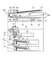
(画像読取装置の構成)
図2に示すように、画像読取装置100は、画像読取部1と原稿搬送部2とを含む。画像読取部1は、原稿Dを読み取って画像データを生成する。原稿搬送部2は、画像読取部1に取り付けられている。そして、原稿搬送部2は、画像読取部1に原稿Dを搬送したり、画像読取部1で読み取る原稿Dを押えたりする。
(Configuration of image reading apparatus)
As shown in FIG. 2, the
原稿搬送部2は、原稿セットトレイ21にセットされた原稿Dを引き出し、原稿搬送路22を介して原稿排出トレイ23に排出する。なお、原稿搬送部2は、複数枚の原稿Dが原稿セットトレイ21にセットされている場合、複数枚の原稿Dのうちから、原稿Dを1枚ずつ連続して引き出す。
The
原稿搬送路22には、原稿搬送方向の上流側から順に、原稿供給ローラー24、原稿搬送ローラー対25および原稿排出ローラー対26が設けられている。そして、原稿セットトレイ21にセットされた原稿Dは、原稿供給ローラー24によって引き出され、原稿搬送ローラー対25によって搬送される。この後、原稿Dは、原稿排出ローラー対26によって原稿排出トレイ23に排出される。なお、原稿供給ローラー24、原稿搬送ローラー対25および原稿排出ローラー対26は、搬送モーターM2(図4参照)と連結される。そして、原稿供給ローラー24、原稿搬送ローラー対25および原稿排出ローラー対26は、搬送モーターM2の駆動力が伝達されることで回転する。
A
画像読取部1は、箱形の筐体を持つ。その筐体の上面の一方端部には、搬送読取用コンタクトガラス20aが配され、筐体の上面の中央部には、載置読取用コンタクトガラス20bが配される。また、筐体の内部には、LEDランプ11、ミラー12、レンズ13およびイメージセンサー14などが設けられている。なお、LEDランプ11は、本発明の「光源」に相当する。
The
LEDランプ11は、原稿Dに照射する光を生成するLED素子を複数含む。複数のLED素子は、図示しないが、読取ライン方向である主走査方向(図2の紙面に対して垂直な方向)にライン状に配列されている。なお、LEDランプ11に代えて、冷陰極管などを用いてもよい。
The
そして、LEDランプ11は、搬送読取用コンタクトガラス20aに搬送される原稿Dの読み取り時には、搬送読取用コンタクトガラス20aに向けて光を照射する(搬送読取用コンタクトガラス20aを透過した光が原稿Dを照射する)。一方で、LEDランプ11は、載置読取用コンタクトガラス20bに載置された原稿Dの読み取り時には、載置読取用コンタクトガラス20bに向けて光を照射する(載置読取用コンタクトガラス20bを透過した光が原稿Dを照射する)。原稿Dで反射された反射光は、ミラー12で反射され、レンズ13に導かれる。レンズ13は、反射光を集光する。
The
イメージセンサー14は、原稿Dで反射された反射光(レンズ13で集光された光)を受光することにより原稿Dをライン単位で読み取る。このイメージセンサー14は、主走査方向にライン状に並ぶ複数の光電変換素子を有するCCDからなり、反射光を受光すると、ライン単位で画素毎に光電変換して電荷を蓄積する。そして、イメージセンサー14は、蓄積電荷に応じたアナログ信号を出力する。すなわち、イメージセンサー14の画素毎のアナログ出力は、反射光の光量に応じて変動する。
The
また、ランプ11およびミラー12は、主走査方向と直交する副走査方向に移動可能な移動枠10によって支持される。すなわち、ランプ11およびミラー12は、移動枠10が副走査方向に移動することにより、移動枠10と共に副走査方向に移動する。なお、移動枠10は、走査モーターM1(図4参照)と連結される。そして、移動枠10(ランプ11およびミラー12)は、走査モーターM1の駆動力が伝達されることで副走査方向に移動する。
The
搬送読取用コンタクトガラス20aに搬送される原稿Dを読み取る場合には、移動枠10が搬送読取用コンタクトガラス20aの下方に移動して静止する。この後、原稿搬送部2が搬送読取用コンタクトガラス20aに原稿Dを搬送する。このとき、搬送読取用コンタクトガラス20aを通過する原稿Dに対してLEDランプ11が光を照射し、原稿Dで反射された反射光の光電変換をイメージセンサー14が連続して繰り返し行う。これにより、原稿Dの読み取りがライン単位で行われる。
When reading the document D conveyed to the conveyance
一方で、載置読取用コンタクトガラス20bに載置された原稿Dを読み取る場合には、移動枠10が副走査方向(正面から見て左から右に向かう方向)に移動する。そして、移動枠10が副走査方向に移動している最中に、載置読取用コンタクトガラス20bに載置された原稿Dに対してLEDランプ11が光を照射し、原稿Dで反射された反射光の光電変換をイメージセンサー14が連続して繰り返し行う。これにより、原稿Dの読み取りがライン単位で行われる。
On the other hand, when reading the document D placed on the placement reading
画像読取部1への原稿搬送部2の取り付けは、画像読取部1に対して原稿搬送部2が開閉可能となるようになされている。具体的には、画像読取部1の背面側に回転軸(図示せず)が設けられ、その回転軸に回動可能に原稿搬送部2が取り付けられている。したがって、原稿搬送部2は、正面側の部分を自由端として、正面側の部分を上下方向に振るようにして回動し、画像読取部1に対して開閉の姿勢をとる。これにより、原稿搬送部2が閉じられると、搬送読取用コンタクトガラス20aおよび載置読取用コンタクトガラス20b)が原稿搬送部2によって覆われる。このため、載置読取用コンタクトガラス20bに載置された原稿Dを読み取るときに、その原稿Dを原稿搬送部2によって押えることができる。
The
原稿搬送部2が閉じられたときに搬送読取用コンタクトガラス20aと対向することになる原稿搬送部2の所定部分には、シェーディング補正で用いる白基準データを取得するための白基準板27が設けられている。すなわち、原稿搬送部2が閉じられた状態では、白基準板27が搬送読取用コンタクトガラス20aと対向配置される。このため、搬送読取用コンタクトガラス20aに原稿Dが搬送されていないときに、搬送読取用コンタクトガラス20aの下方においてLEDランプ11が点灯すると、LEDランプ11からの光が白基準板27で反射される。すなわち、イメージセンサー14によって白基準板27の読み取りが行われる。この場合には、白基準板27が読取対象となる。
A
(画像形成装置のハードウェア構成)
図3に示すように、画像形成装置200は、本体制御部210を備える。本体制御部210は、CPU211、記憶部212および画像処理部213などを含む。記憶部212は、ROMやRAMなどからなり、たとえば、各種のプログラムおよびデータがROMに記憶され、RAMに展開される。また、画像処理部213は、画像処理専用のASICおよびメモリーなどからなっており、画像データに対して、拡大/縮小、濃度変換およびデータ形式変換などの各種の画像処理を施す。
(Hardware configuration of image forming apparatus)
As shown in FIG. 3, the
また、本体制御部210は、エンジン部7(給紙部3、用紙搬送部4、画像形成部5および定着部6)および操作パネル8と接続される。そして、本体制御部210は、記憶部212に記憶された各種のプログラムおよびデータに基づき、各部の制御や演算などを行う。さらに、本体制御部210は、画像読取装置100(画像読取部1および原稿搬送部2)と接続され、画像読取部1および原稿搬送部2の制御も行う。
The main
さらに、本体制御部210は、画像形成装置200の周囲の温湿度を測定するための温湿度センサー9と接続され、画像形成装置200の周囲の温湿度を検知する。そして、本体制御部210は、画像形成装置200の周囲の温湿度に応じた印刷設定値(たとえば、エンジン部7の各部に供給する電圧値など)を決定する。一例として、画像形成装置200の周囲の温湿度の変動により、用紙Pや転写ローラー55などの抵抗値が変化する。このため、本体制御部210は、画像形成装置200の周囲の温湿度に応じて、転写ローラー55に印加する転写電圧などを設定変更する。
Further, the main
(画像読取装置のハードウェア構成)
図4に示すように、画像読取装置100は、画像読取部1の搬送動作を制御する読取制御部110と、原稿搬送部2の読取動作を制御する搬送制御部120とを備える。
(Hardware configuration of image reading apparatus)
As shown in FIG. 4, the
搬送制御部120は、CPU121および記憶部122(ROMやRAM)などを含むとともに、本体制御部210から指示を受けて動作する。具体的には、搬送制御部120は、原稿供給ローラー24、原稿搬送ローラー対25および原稿排出ローラー対26を回転させるための搬送モーターM2と接続される。そして、搬送制御部120は、搬送モーターM2の駆動を制御し、原稿供給ローラー24、原稿搬送ローラー対25および原稿排出ローラー対26を適切に回転させる。
The
読取制御部110は、CPU111および記憶部112(ROMやRAM)などを含むとともに、本体制御部210から指示を受けて動作する。具体的には、読取制御部110は、移動枠10(ランプ11およびミラー12)を副走査方向に移動させるための走査モーターM1と接続される。そして、読取制御部110は、走査モーターM1の駆動を制御し、移動枠10(ランプ11およびミラー12)を適切な位置に移動させる。
The
また、読取制御部110は、イメージセンサー14、PWM信号生成部15、LED駆動部16、アナログ処理部17、A/D変換部18および画像メモリー19と接続され、これら各部の制御も行う。
The
PWM信号生成部15は、読取制御部110から指示を受け、LEDランプ11の光量(発光レベル)をPWM調光方式で調整するためのPWM信号を生成し、LED駆動部16に出力する。すなわち、PWM信号生成部15と接続される読取制御部110は、本発明の「光量調整部」に相当する。なお、PWM調光方式というのは、LEDランプ11を周期的に点滅させ、その点灯期間と消灯期間との時間比率を変化させることによって調光する方式のことである。そして、LED駆動部16は、PWM信号に基づきLEDランプ11を点灯(点滅)させる。
The PWM
アナログ処理部17は、イメージセンサー14のアナログ出力に対して増幅処理などを行う回路である。このアナログ処理部17は、白基準を調整するためのゲイン調整を行うゲイン調整部17a、および、黒基準を調整するためのオフセット調整を行うオフセット調整部17bなどを含む。A/D変換部18は、たとえば、アナログ処理部17で処理されたイメージセンサー14のアナログ出力を0〜255階調に量子化し、デジタルの画像データ(濃度データ)に変換して出力する。画像メモリー19は、A/D変換部18から出力された画像データを蓄積し、本体制御部210に転送する。
The
そして、画像データを受けた本体制御部210は、画像データに対して各種の画像処理を施し、露光用の画像データ(露光装置53の発光素子を点消灯させるための画像データ)を生成する。
Upon receiving the image data, the main
また、読取制御部110は、温湿度センサー9と接続される。あるいは、読取制御部110は、本体制御部210を介して、温湿度センサー9の出力を受ける。そして、読取制御部110は、温湿度センサー9の出力に基づき、画像読取装置100の周囲の温度を検知する。すなわち、温湿度センサー9は、本発明の「温度センサー」に相当する。
The
(画像読取装置の初期調整)
画像読取装置100は、工場出荷時に、LEDランプ11の光量調整、白基準を調整するためのゲイン調整、および、黒基準を調整するためのオフセット調整、などの複数の調整を含む初期調整を行う。
(Initial adjustment of image reader)
The
LEDランプ11の光量調整では、読取制御部110は、LEDランプ11を白基準板27の下方に移動させる。そして、読取制御部110は、LED駆動部16に指示し、LEDランプ11を点灯(点滅)させる。これにより、白基準板27で反射された反射光がイメージセンサー14に入射される。すなわち、読取制御部110は、白基準板27の読み取りをイメージセンサー14に行わせる。
In the light amount adjustment of the
ここで、イメージセンサー14のアナログ出力は、アナログ処理部17により処理されてから、A/D変換部18によりA/D変換される。このときにA/D変換されたデジタル値は、イメージセンサー14のアナログ出力が大きいほど大きくなる。すなわち、読取対象の画像が明るいほどA/D変換後のデジタル値は大きくなり、読取対象の画像が暗いほどA/D変換後のデジタル値は小さくなる。
Here, the analog output of the
しかし、アナログ処理部17により処理されたイメージセンサー14のアナログ出力がA/D変換部18の入力電圧範囲(変換可能範囲)の上限値を超えると、イメージセンサー14のアナログ出力が大きくなる方向に変化しても、A/D変換後のデジタル値は変化せず、全て最高デジタル値に変換される。このため、白基準板27を読み取ったイメージセンサー14のアナログ出力(アナログ処理部17により処理されたイメージセンサー14のアナログ出力の最大値)がA/D変換部18の入力電圧範囲の上限値を超えないようにしなければならない。
However, when the analog output of the
なお、アナログ処理部17(ゲイン調整部17a)のゲイン設定値は1以上である。したがって、白基準板27を読み取ったイメージセンサー14のアナログ出力がA/D変換部18の入力電圧範囲の上限値を超える場合には、ゲイン設定値の調整では対応できない。このため、読取制御部110は、LEDランプ11の光量を減少させる(光量調整を行う)ことにより、白基準板27を読み取ったイメージセンサー14のアナログ出力がA/D変換部18の入力電圧範囲の上限値を超えないようにする。
The gain setting value of the analog processing unit 17 (gain adjusting
読取制御部110は、LEDランプ11の光量を減少させるとき、PWM信号生成部15に指示し、LED駆動部16に出力されるPWM信号のデューティ比を予め設定された刻み幅で段階的に小さくする。これにより、LEDランプ11の光量が段階的に減少する。なお、読取制御部110は、白基準板27を読み取ったイメージセンサー14のアナログ出力(アナログ処理部17により処理されたイメージセンサー14のアナログ出力の最大値)がA/D変換部18の入力電圧範囲に収まるまで、LEDランプ11の光量を減少させる。その後、読取制御部110は、白基準板27を読み取ったイメージセンサー14のアナログ出力がA/D変換部18の入力電圧範囲に収まると(イメージセンサー14のアナログ処理後のアナログ出力の最大値がA/D変換部18の入力電圧範囲の上限値に近づくと)、光量調整を終了する。そして、読取制御部110は、このときのPWM信号のデューティ比を光量設定値として記憶部112に記憶させる。
When the
また、白基準板27を読み取ったイメージセンサー14のアナログ出力(アナログ処理部17により処理されたイメージセンサー14のアナログ出力の最大値)がA/D変換部18の入力電圧範囲の上限値を大きく下回ると、読み取り可能な色域(読み取り可能な濃度レンジ)が狭くなる。このため、白基準板27を読み取ったイメージセンサー14のアナログ出力がA/D変換部18の入力電圧範囲の上限値に近づくようにしなければならない。したがって、この場合には、読取制御部110は、LEDランプ11の光量を増大させる(光量調整を行う)ことにより、白基準板27を読み取ったイメージセンサー14のアナログ出力がA/D変換部18の入力電圧範囲の上限値に近づくようにする。
Further, the analog output of the
白基準を調整するためのゲイン調整では、読取制御部110は、白基準板27の読み取りをイメージセンサー14に行わせる。そして、読取制御部110は、白基準板27を読み取ったイメージセンサー14のアナログ出力(アナログ処理部17で処理されたアナログ出力の最大値)がA/D変換部18の入力電圧範囲の上限値に近づくように、ゲイン調整部17aのゲイン設定値を設定する。
In gain adjustment for adjusting the white reference, the
また、黒基準を調整するためのオフセット調整では、読取制御部110は、LEDランプ11を消灯させる。そして、読取制御部110は、LEDランプ11を消灯させたときのイメージセンサー14のアナログ出力(アナログ処理部17で処理されたアナログ出力)がA/D変換部18の入力電圧範囲の下限値に近づくように、オフセット調整部17bのオフセット設定値を設定する。
In the offset adjustment for adjusting the black reference, the
このように、工場出荷時には、光量調整、ゲイン調整およびオフセット調整などの複数の調整を含む初期調整が行われる。しかし、LEDランプ11やイメージセンサー14は、時間の経過と共に特性が変化する。また、白基準板27に汚れが発生することもある。このため、初期調整は、工場出荷時だけでなく、たとえば、工場出荷後の装置起動時にも行われるようになっている。ただし、初期調整を装置起動時に行うと、装置への電源投入からジョブの実行が可能になるまでに時間がかかり、ユーザーにとっては利便性が悪い。
Thus, at the time of shipment from the factory, initial adjustment including a plurality of adjustments such as light amount adjustment, gain adjustment, and offset adjustment is performed. However, the characteristics of the
このため、本実施形態では、光量調整以外の調整(ゲイン調整およびオフセット調整など)については、工場出荷後の装置起動時に毎回行う。一方で、光量調整については、工場出荷後の装置起動時に行う場合もあれば、工場出荷後の装置起動時に行わない場合もある。なお、以下の説明では、光量調整、ゲイン調整およびオフセット調整などの複数の調整を全て含む初期調整を通常調整と称し、光量調整を含まない初期調整を簡易調整と称する場合がある。 For this reason, in this embodiment, adjustments other than the light amount adjustment (such as gain adjustment and offset adjustment) are performed every time the apparatus is started up after factory shipment. On the other hand, the light amount adjustment may be performed when the apparatus is started after shipment from the factory, or may not be performed when the apparatus is started after shipment from the factory. In the following description, initial adjustment including all of a plurality of adjustments such as light amount adjustment, gain adjustment, and offset adjustment may be referred to as normal adjustment, and initial adjustment not including light amount adjustment may be referred to as simple adjustment.
工場出荷後の装置起動時に通常調整および簡易調整のいずれの調整を初期調整として行うか(光量調整を行うか否か)については、装置起動時の装置周囲の温度に基づき読取制御部110が判断する。具体的には、LEDランプ11は、装置周囲の温度が高いほど発光効率が下がり、装置周囲の温度が低いほど発光効率が上がる。すなわち、装置周囲の温度が低いと、LEDランプ11の光量が増大し、装置周囲の温度が高いと、LEDランプ11の光量が減少する。したがって、前回の通常調整時(光量調整時)の装置周囲の温度に対して現在の装置周囲の温度が大きく変化していれば、白基準板27を読み取ったイメージセンサー14のアナログ出力(アナログ処理17により処理されたイメージセンサー14のアナログ出力の最大値)がA/D変換部18の入力電圧範囲の上限値から大きく外れた値となる可能性がある。その一方、前回の通常調整時(光量調整時)の装置周囲の温度に対して現在の装置周囲の温度が殆ど変化していない場合には、現在のLEDランプ11の光量は前回の通常調整時のLEDランプ11の光量と比べて殆ど変化しない。したがって、この場合には、光量調整を敢えて行う必要はない。
Whether the normal adjustment or the simple adjustment is performed as the initial adjustment when starting the apparatus after shipment from the factory (whether or not the light amount adjustment is performed) is determined by the
そこで、読取制御部110は、工場での通常調整時(光量調整時)に、装置周囲の温度を検知し、工場での通常調整時の装置周囲の温度を示す温度データを記憶部112に記憶させる。たとえば、読取制御部110は、工場での通常調整時に、転写電圧の調整などに用いる温湿度センサー9(画像形成装置200の本体に元々装着されているセンサー)の出力に基づき装置周囲の温度を検知する。あるいは、図示しないが、光量調整用の温度センサーを画像読取装置100に別途装着し、その光量調整用の温度センサーの出力に基づき装置周囲の温度を検知してもよい。
Therefore, the
そして、読取制御部110は、工場出荷後の最初の装置起動時に、装置起動時の装置周囲の温度を検知する。また、読取制御部110は、記憶部112に既に記憶された温度(工場での通常調整時の装置周囲の温度)と、現在の装置周囲の温度(工場出荷後の最初の装置起動時の装置周囲の温度)とを比較する。この比較の結果、記憶部112に既に記憶された温度と現在の装置周囲の温度との温度差の絶対値が予め定められた閾値以上であれば、読取制御部110は、光量調整を含む通常調整を行う。その一方、記憶部112に既に記憶された温度と現在の装置周囲の温度との温度差の絶対値が閾値よりも小さければ、読取制御部110は、光量調整を含まない簡易調整を行う。すなわち、光量調整は行わない。
The
たとえば、装置起動時に通常調整および簡易調整のいずれを行うかの判断基準となる閾値は、10℃に設定される。あるいは、装置周囲の温度を変化させつつLEDランプ11の発光効率を測定し、LEDランプ11の発光効率が数%〜数十%ほど変化した時点の装置周囲の温度とLEDランプ11の発光効率が変化する前の装置周囲の温度との温度差の絶対値を閾値として設定してもよい。
For example, a threshold value that is a criterion for determining whether normal adjustment or simple adjustment is performed when the apparatus is activated is set to 10 ° C. Alternatively, the luminous efficiency of the
読取制御部110は、工場出荷後の最初の装置起動時に光量調整を含む通常調整を行うと、記憶部112に既に記憶された温度データを現在の装置周囲の温度を示す温度データに更新する。したがって、工場出荷後の最初の装置起動時に光量調整を含む通常調整が行われた場合、工場での通常調整時の装置周囲の温度を示す温度データは、工場出荷後の最初の装置起動時(通常調整時)の装置周囲の温度を示す温度データに更新される。一方で、読取制御部110は、工場出荷後の最初の装置起動時に光量調整を含まない簡易調整を行った場合、記憶部112に既に記憶された温度データの更新は行わない。すなわち、この場合には、工場での通常調整時の装置周囲の温度を示す温度データがそのまま記憶部112に保持される。
When the
この後、読取制御部110は、装置が起動される度に、装置起動時の装置周囲の温度を検知し、装置起動時の装置周囲の温度に基づいて、通常調整および簡易調整のいずれを行うか(光量調整を行うか否か)を判断する。このとき、工場出荷後に通常調整が既に行われていれば、工場出荷後の通常調整時の装置周囲の温度と現在の装置周囲の温度とが比較される。一方で、工場出荷後に通常調整が行われていなければ、工場での通常調整時の装置周囲の温度と現在の装置周囲の温度とが比較される。いずれにしても、読取制御部110は、装置が起動される度に、通常調整または簡易調整を行うことになる。そして、読取制御部110は、通常調整(光量調整)を行う度に、記憶部112に既に記憶された温度データを現在の装置周囲の温度を示す温度データに更新する。
Thereafter, each time the apparatus is activated, the
ところで、工場出荷後の装置起動時において、前回の通常調整時(光量調整時)の装置周囲の温度に対して現在の装置周囲の温度が高くなっている場合には、LEDランプ11の発光効率が低下することにより、現在のLEDランプ11の光量は前回の通常調整時のLEDランプ11の光量と比べて減少する。このため、白基準板27を読み取ったイメージセンサー14のアナログ出力(アナログ処理部17で処理されたアナログ出力の最大値)はA/D変換部18の入力電圧範囲の上限値を超えないので、ゲイン設定値の調整だけで対応できる。したがって、記憶部112に既に記憶された温度(前回の通常調整時の装置周囲の温度)よりも現在の装置周囲の温度が閾値以上低い場合にのみ、光量調整を含む通常調整が行われるようになっていてもよい。これにより、記憶部112に既に記憶された温度(前回の通常調整時の装置周囲の温度)よりも現在の装置周囲の温度が閾値以上低くない場合には、光量調整が行われない(簡易調整が行われる)ので、初期調整にかかる時間が短縮される。
By the way, at the time of starting the apparatus after shipment from the factory, if the current temperature around the apparatus is higher than the temperature around the apparatus at the time of the previous normal adjustment (when adjusting the amount of light), the luminous efficiency of the
(初期調整の流れ)
まず、図5に示すフローチャートを参照し、工場出荷時の初期調整(光量調整、ゲイン調整およびオフセット調整などの複数の調整を全て含む通常調整)の流れについて説明する。
(Initial adjustment flow)
First, the flow of initial adjustment (normal adjustment including all of a plurality of adjustments such as light amount adjustment, gain adjustment, and offset adjustment) at the time of factory shipment will be described with reference to a flowchart shown in FIG.
図5のフローチャートのスタートは、工場において通常調整を行うために画像読取装置100に電源が投入されたときである。なお、図5のフローチャートのスタート時点では、従前に通常調整(光量調整)は行われていない。したがって、記憶部112には、通常調整時(光量調整時)の装置周囲の温度を示す温度データは記憶されていない。
The start of the flowchart of FIG. 5 is when the
ステップS1において、読取制御部110は、光量調整を含む通常調整を行う。また、ステップS2において、読取制御部110は、温湿度センサー9の出力に基づき、現在の装置周囲の温度を検知する。そして、ステップS3において、読取制御部110は、通常調整時(光量調整時)の装置周囲の温度を示す温度データを記憶部112に記憶させる。
In step S1, the
次に、図6に示すフローチャートを参照し、工場出荷後の装置起動時の流れについて説明する。 Next, with reference to the flowchart shown in FIG. 6, the flow at the time of starting the apparatus after factory shipment will be described.
図6のフローチャートのスタートは、工場出荷後に画像読取装置100に電源が投入されたときである。なお、図6のフローチャートのスタート時点では、通常調整(光量調整)が既に行われている。したがって、記憶部112には、通常調整時(光量調整時)の装置周囲の温度を示す温度データが記憶されている。
The start of the flowchart of FIG. 6 is when the
ステップS11において、読取制御部110は、温湿度センサー9の出力に基づき、現在の装置周囲の温度を検知する。そして、ステップS12において、読取制御部110は、記憶部112に既に記憶された温度(前回の通常調整時の装置周囲の温度)と現在の装置周囲の温度との温度差の絶対値が閾値(たとえば、10℃)以上であるか否かを判断する。その結果、記憶部112に既に記憶された温度と現在の装置周囲の温度との温度差の絶対値が閾値以上であれば、ステップS13に移行する。
In step S <b> 11, the
ステップS13に移行すると、読取制御部110は、光量調整を含む通常調整を行う。続いて、ステップS14において、読取制御部110は、通常調整時(光量調整時)の装置周囲の温度を示す温度データを記憶部112に記憶させる。すなわち、記憶部112は、温度データを現在の温度を示す温度データに更新する。
In step S13, the
一方で、ステップS12において、記憶部112に既に記憶された温度と現在の装置周囲の温度との温度差の絶対値が閾値よりも小さければ、ステップS15に移行する。ステップS15に移行すると、読取制御部110は、光量調整を含まない簡易調整を実行する。なお、ステップS15に移行した場合には、記憶部112に既に記憶された温度データの更新は行わない。
On the other hand, if the absolute value of the temperature difference between the temperature already stored in the
本実施形態の画像読取装置100(画像形成装置200)は、上記のように、読取対象に光を照射するLEDランプ11(本発明の「光源」に相当)と、読取対象で反射された反射光を受光することにより読取対象を読み取るイメージセンサー14と、イメージセンサー14のアナログ出力をアナログ処理するアナログ処理部17と、アナログ処理部17で処理されたイメージセンサー14のアナログ出力をデジタルの画像データに変換するA/D変換部18と、アナログ処理部17で処理されたイメージセンサー14のアナログ出力の最大値がA/D変換部18の入力電圧範囲の上限値を超えることなくその上限値に近づくようにLEDランプ11の光量調整を行う読取制御部110(本発明の「光量調整部」に相当)と、画像読取装置200の周囲の温度を測定するための温湿度センサー9(本発明の「温度センサー」に相当)と、光量調整時の画像読取装置100の周囲の温度を示す温度データを記憶する記憶部112と、を備えている。そして、読取制御部110は、記憶部112に記憶された温度と現在の温度との温度差の絶対値が予め定められた閾値よりも小さければ、光量調整を行わず、記憶部112に記憶された温度と現在の温度との温度差の絶対値が閾値以上であれば、光量調整を行う。
As described above, the image reading apparatus 100 (image forming apparatus 200) of the present embodiment includes the LED lamp 11 (corresponding to the “light source” of the present invention) that irradiates light to the reading target, and the reflection reflected by the reading target. An
ここで、LEDランプ11の光量は温度に依存する。具体的には、温度が低くなるほどLEDランプ11の発光効率が上昇することによりLEDランプ11の光量が増加するとともに、温度が高くなるほどLEDランプ11の発光効率が低下することによりLEDランプ11の光量が減少する。これにより、現在の温度が前回の光量調整時の温度に対して殆ど変化していなければ、前回の光量調整時に設定された光量設定値のままでLEDランプ11を駆動したとしても、イメージセンサー14のアナログ出力の最大値はA/D変換部18の入力電圧範囲の上限値を超えない値(上限値に近い値)に保持されるので、光量調整を敢えて行う必要はない。ただし、現在の温度が前回の光量調整時の温度に対して大きく変化していれば、前回の光量調整時に設定された光量設定値のままでLEDランプ11を駆動すると、イメージセンサー14のアナログ出力の最大値がA/D変換部18の入力電圧範囲の上限値を超える可能性があるので、光量調整を行った方が良い。
Here, the light quantity of the
そこで、本実施形態の構成では、記憶部112に記憶された温度(前回の光量調整時の温度)と現在の温度との温度差の絶対値が閾値よりも小さければ、前回の光量調整時の温度に対して現在の温度が殆ど変化していないものとして光量調整を行わない。これにより、光量調整を省略する分、画像読取装置200の初期調整にかかる時間を短くすることができる。したがって、画像読取装置200が初期調整に入ったとしても、ジョブの実行が可能になるまでの待ち時間が短くなるので、ユーザーの利便性が向上する。また、この場合には、前回の光量調整時の温度に対して現在の温度が殆ど変化していない(LEDランプ11の光量が殆ど変化しない)ので、光量調整を行わなかったとしても、イメージセンサー14のアナログ出力の最大値はA/D変換部18の入力電圧範囲の上限値を超えない値(上限値に近い値)に保持される。これにより、A/D変換部18の出力が飽和することに起因する画質の低下が防止される。
Therefore, in the configuration of the present embodiment, if the absolute value of the temperature difference between the temperature stored in the storage unit 112 (temperature at the previous light intensity adjustment) and the current temperature is smaller than the threshold value, The light amount adjustment is not performed on the assumption that the current temperature has hardly changed with respect to the temperature. As a result, the time required for the initial adjustment of the
なお、本実施形態の構成では、記憶部112に記憶された温度(前回の光量調整時の温度)と現在の温度との温度差の絶対値が閾値以上であれば、前回の光量調整時の温度に対して現在の温度が大きく変化しているものとして光量調整を行う。すなわち、イメージセンサー14のアナログ出力の最大値がA/D変換部18の入力電圧範囲の上限値を超える可能性がある場合には、光量調整を行う。これにより、A/D変換部18の出力が飽和しないので、画質の低下を抑制することができる。
In the configuration of the present embodiment, if the absolute value of the temperature difference between the temperature stored in the storage unit 112 (the temperature at the previous light amount adjustment) and the current temperature is equal to or greater than the threshold value, The light amount is adjusted on the assumption that the current temperature is greatly changed with respect to the temperature. That is, when there is a possibility that the maximum value of the analog output of the
また、本実施形態では、上記のように、アナログ処理部17がゲイン調整部17a(調整部)およびオフセット調整部17b(調整部)を含み、画像読取装置100の初期調整として、白基準を調整するためのゲイン調整(ゲイン調整部17aのゲイン設定値の調整)、および、黒基準を調整するためのオフセット調整(オフセット調整部17bのオフセット設定値の調整)が行われる。そして、ゲイン調整およびオフセット調整は、記憶部112に記憶された温度(前回の光量調整時の温度)と現在の温度との温度差にかかわらず行われる。すなわち、読取制御部110は、記憶部112に記憶された温度と現在の温度との温度差の絶対値が閾値よりも小さければ、光量調整を行わず、ゲイン調整およびオフセット調整を行う。一方で、読取制御部110は、記憶部112に記憶された温度と現在の温度との温度差の絶対値が閾値以上であれば、光量調整を行うとともに、ゲイン調整およびオフセット調整を行う。ここで、前回の光量調整時の温度に対して現在の温度が殆ど変化していなかったとしても、LEDランプ11やイメージセンサー14の特性あるいは白基準板27の汚れ具合などは経時的に変化する。このため、光量調整を行わない場合であっても、ゲイン調整やオフセット調整などについては行うように構成している。
In the present embodiment, as described above, the
また、本実施形態では、上記のように、光量調整が行われる度に、記憶部112に記憶されている温度データが現在の温度を示す温度データに更新される。このように構成すれば、光量調整を行うか否かの判断に際して、容易に、現在の温度と前回の光量調整時の温度とを比較することができる。
In the present embodiment, as described above, each time the light amount is adjusted, the temperature data stored in the
また、本実施形態では、上記のように、読取制御部110は、装置起動時に、記憶部112に記憶された温度と装置起動時の温度(現在の温度)との温度差の絶対値が閾値よりも小さければ、光量調整を行わず、記憶部112に記憶された温度と装置起動時の温度(現在の温度)との温度差の絶対値が閾値以上であれば、光量調整を行う。このように構成すれば、装置への電源投入からジョブの実行が可能になるまでの待ち時間を短くすることができる。
In the present embodiment, as described above, the
今回開示された実施形態は、すべての点で例示であって、制限的なものではないと考えられるべきである。本発明の範囲は、上記実施形態の説明ではなく特許請求の範囲によって示され、さらに、特許請求の範囲と均等の意味および範囲内でのすべての変更が含まれる。 It should be thought that embodiment disclosed this time is an illustration and restrictive at no points. The scope of the present invention is shown not by the description of the above-described embodiment but by the scope of claims for patent, and further includes meanings equivalent to the scope of claims for patent and all modifications within the scope.
たとえば、上記実施形態では、装置起動時に初期調整(通常調整または簡易調整)を行うようにしたが、本発明はこれに限らない。具体的には、装置起動中のジョブが実行されていない所定の時点(たとえば、ジョブ開始前やジョブ終了後)に、記憶部112に既に記憶された温度(前回の通常調整時の装置周囲の温度)と現在の装置周囲の温度と比較して、その結果に基づき通常調整または簡易調整を行うようにしてもよい。
For example, in the above embodiment, the initial adjustment (normal adjustment or simple adjustment) is performed when the apparatus is activated, but the present invention is not limited to this. Specifically, the temperature already stored in the
9 温湿度センサー(温度センサー)
11 LEDランプ(光源)
14 イメージセンサー
17 アナログ処理部
17a ゲイン調整部(調整部)
17b オフセット調整部(調整部)
18 A/D変換部
100 画像読取装置
110 読取制御部(光量調整部)
200 画像形成装置
112 記憶部
9 Temperature / humidity sensor (temperature sensor)
11 LED lamp (light source)
14
17b Offset adjustment unit (adjustment unit)
18 A /
200
Claims (6)
前記読取対象で反射された反射光を受光することにより前記読取対象を読み取るイメージセンサーと、
前記イメージセンサーのアナログ出力をアナログ処理するアナログ処理部と、
前記アナログ処理部で処理された前記イメージセンサーのアナログ出力をデジタルの画像データに変換するA/D変換部と、
前記アナログ処理部で処理された前記イメージセンサーのアナログ出力の最大値が前記A/D変換部の入力電圧範囲の上限値を超えることなく前記上限値に近づくように前記光源の光量調整を行う光量調整部と、
画像読取装置の周囲の温度を測定するための温度センサーと、
前記光量調整時の画像読取装置の周囲の温度を示す温度データを記憶する記憶部と、を備え、
前記光量調整部は、前記記憶部に記憶された温度と現在の温度との温度差の絶対値が予め定められた閾値よりも小さければ、前記光量調整を行わず、前記記憶部に記憶された温度と現在の温度との温度差の絶対値が前記閾値以上であれば、前記光量調整を行うことを特徴とする画像読取装置。 A light source for irradiating the reading object with light;
An image sensor that reads the reading object by receiving reflected light reflected by the reading object;
An analog processing unit for analog processing of the analog output of the image sensor;
An A / D converter that converts the analog output of the image sensor processed by the analog processor into digital image data;
The light amount for adjusting the light amount of the light source so that the maximum value of the analog output of the image sensor processed by the analog processing unit approaches the upper limit value without exceeding the upper limit value of the input voltage range of the A / D conversion unit An adjustment unit;
A temperature sensor for measuring the ambient temperature of the image reader;
A storage unit for storing temperature data indicating the ambient temperature of the image reading device at the time of the light amount adjustment,
If the absolute value of the temperature difference between the temperature stored in the storage unit and the current temperature is smaller than a predetermined threshold, the light amount adjustment unit does not perform the light amount adjustment and is stored in the storage unit. The image reading apparatus, wherein the light amount adjustment is performed when an absolute value of a temperature difference between a temperature and a current temperature is equal to or greater than the threshold value.
前記記憶部に記憶された温度と現在の温度との温度差の絶対値が前記閾値よりも小さければ、前記光量調整部は前記光量調整を行わず、前記調整部は前記ゲイン調整および前記オフセット調整を行う一方、前記記憶部に記憶された温度と現在の温度との温度差の絶対値が前記閾値以上であれば、前記光量調整部は前記光量調整を行うとともに、前記調整部は前記ゲイン調整および前記オフセット調整を行うことを特徴とする請求項1に記載の画像読取装置。 The analog processing unit includes a gain adjustment for adjusting a white reference, and an adjustment unit for performing an offset adjustment for adjusting a black reference,
If the absolute value of the temperature difference between the temperature stored in the storage unit and the current temperature is smaller than the threshold value, the light amount adjustment unit does not perform the light amount adjustment, and the adjustment unit performs the gain adjustment and the offset adjustment. On the other hand, if the absolute value of the temperature difference between the temperature stored in the storage unit and the current temperature is equal to or greater than the threshold value, the light amount adjustment unit performs the light amount adjustment, and the adjustment unit performs the gain adjustment. The image reading apparatus according to claim 1, wherein the offset adjustment is performed.
Priority Applications (2)
| Application Number | Priority Date | Filing Date | Title |
|---|---|---|---|
| JP2013064350A JP5865861B2 (en) | 2013-03-26 | 2013-03-26 | Image reading apparatus and image forming apparatus |
| US14/221,107 US8896895B2 (en) | 2013-03-26 | 2014-03-20 | Image reading apparatus and image forming apparatus |
Applications Claiming Priority (1)
| Application Number | Priority Date | Filing Date | Title |
|---|---|---|---|
| JP2013064350A JP5865861B2 (en) | 2013-03-26 | 2013-03-26 | Image reading apparatus and image forming apparatus |
Publications (2)
| Publication Number | Publication Date |
|---|---|
| JP2014192579A true JP2014192579A (en) | 2014-10-06 |
| JP5865861B2 JP5865861B2 (en) | 2016-02-17 |
Family
ID=51620587
Family Applications (1)
| Application Number | Title | Priority Date | Filing Date |
|---|---|---|---|
| JP2013064350A Expired - Fee Related JP5865861B2 (en) | 2013-03-26 | 2013-03-26 | Image reading apparatus and image forming apparatus |
Country Status (2)
| Country | Link |
|---|---|
| US (1) | US8896895B2 (en) |
| JP (1) | JP5865861B2 (en) |
Families Citing this family (3)
| Publication number | Priority date | Publication date | Assignee | Title |
|---|---|---|---|---|
| JP6142815B2 (en) * | 2014-02-13 | 2017-06-07 | ブラザー工業株式会社 | Image reading device |
| CN108538258B (en) * | 2017-03-06 | 2023-03-24 | 北京小米移动软件有限公司 | Method and device for adjusting backlight current and display equipment |
| JP6809501B2 (en) * | 2018-04-09 | 2021-01-06 | 京セラドキュメントソリューションズ株式会社 | Image reader, image forming device |
Citations (2)
| Publication number | Priority date | Publication date | Assignee | Title |
|---|---|---|---|---|
| JPS621363A (en) * | 1985-06-27 | 1987-01-07 | Brother Ind Ltd | Picture input device |
| JP2011061433A (en) * | 2009-09-09 | 2011-03-24 | Canon Inc | Image reading apparatus |
Family Cites Families (12)
| Publication number | Priority date | Publication date | Assignee | Title |
|---|---|---|---|---|
| JPH113007A (en) | 1997-06-13 | 1999-01-06 | Canon Inc | Image forming device and its adjustment method |
| US20070188584A1 (en) * | 2006-02-13 | 2007-08-16 | Matsushita Electric Industrial Co., Ltd. | Image forming apparatus |
| JP2009282187A (en) * | 2008-05-21 | 2009-12-03 | Renesas Technology Corp | Liquid crystal driving device |
| WO2010004749A1 (en) * | 2008-07-09 | 2010-01-14 | パナソニック株式会社 | Wavelength conversion laser light source, and projection display device, liquid crystal display device, and laser light source provided with same |
| US8456092B2 (en) * | 2008-09-05 | 2013-06-04 | Ketra, Inc. | Broad spectrum light source calibration systems and related methods |
| US8471496B2 (en) * | 2008-09-05 | 2013-06-25 | Ketra, Inc. | LED calibration systems and related methods |
| JP5029924B2 (en) * | 2009-05-28 | 2012-09-19 | ブラザー工業株式会社 | Image reading apparatus and image forming apparatus |
| JP2011188224A (en) * | 2010-03-09 | 2011-09-22 | Sony Corp | Temperature information output device, imaging apparatus, and temperature information output method |
| JP5754955B2 (en) * | 2011-01-26 | 2015-07-29 | キヤノン株式会社 | Image forming apparatus |
| JP2012247503A (en) * | 2011-05-25 | 2012-12-13 | Canon Inc | Image forming device |
| US8928249B2 (en) * | 2011-08-25 | 2015-01-06 | Abl Ip Holding Llc | Reducing lumen variability over a range of color temperatures of an output of tunable-white LED lighting devices |
| JP5956949B2 (en) * | 2013-03-22 | 2016-07-27 | 株式会社日立エルジーデータストレージ | Image display device |
-
2013
- 2013-03-26 JP JP2013064350A patent/JP5865861B2/en not_active Expired - Fee Related
-
2014
- 2014-03-20 US US14/221,107 patent/US8896895B2/en not_active Expired - Fee Related
Patent Citations (2)
| Publication number | Priority date | Publication date | Assignee | Title |
|---|---|---|---|---|
| JPS621363A (en) * | 1985-06-27 | 1987-01-07 | Brother Ind Ltd | Picture input device |
| JP2011061433A (en) * | 2009-09-09 | 2011-03-24 | Canon Inc | Image reading apparatus |
Also Published As
| Publication number | Publication date |
|---|---|
| US8896895B2 (en) | 2014-11-25 |
| US20140293364A1 (en) | 2014-10-02 |
| JP5865861B2 (en) | 2016-02-17 |
Similar Documents
| Publication | Publication Date | Title |
|---|---|---|
| US9479675B2 (en) | Image reading device and image forming apparatus | |
| JP2012142948A (en) | Image reader and control method of the same | |
| JP5865861B2 (en) | Image reading apparatus and image forming apparatus | |
| US20150229810A1 (en) | Image reader, and method and computer-readable medium therefor | |
| JP2004320333A (en) | Copying apparatus | |
| JP6819556B2 (en) | Image forming device | |
| JP5757922B2 (en) | Image reading apparatus and image forming apparatus | |
| JP5842625B2 (en) | Document reading apparatus, image forming apparatus, and document reading method | |
| JP5909458B2 (en) | Image reading apparatus and image forming apparatus | |
| JP6264875B2 (en) | Image reading apparatus and image forming apparatus | |
| JP2004040443A (en) | Image reader and image processor | |
| JP2014135676A (en) | Imaging apparatus, image reading apparatus and image forming apparatus | |
| JP2012138879A (en) | Image reading device and image forming apparatus | |
| JP5703162B2 (en) | Image reading apparatus and image forming apparatus having the same | |
| JP5948460B2 (en) | Image reading apparatus and image forming apparatus | |
| JP2010004444A (en) | Image reader | |
| JP5897494B2 (en) | Image reading apparatus, image forming apparatus, and image reading method | |
| JP2014127907A (en) | Illumination device for original and original reading device having the same device | |
| JP2011061695A (en) | Image reading apparatus and method, and program | |
| JP2023077497A (en) | Image reading device and image formation device | |
| JP6188572B2 (en) | Image reading apparatus and image reading method | |
| JP6041441B2 (en) | Image reading apparatus and image forming apparatus having the same | |
| JP2013106309A (en) | Image reading device, and image forming apparatus | |
| JP2010021946A (en) | Original reading device and image forming apparatus | |
| JP2010252043A (en) | Image reader and image forming apparatus |
Legal Events
| Date | Code | Title | Description |
|---|---|---|---|
| A621 | Written request for application examination |
Free format text: JAPANESE INTERMEDIATE CODE: A621 Effective date: 20150119 |
|
| A977 | Report on retrieval |
Free format text: JAPANESE INTERMEDIATE CODE: A971007 Effective date: 20150416 |
|
| A131 | Notification of reasons for refusal |
Free format text: JAPANESE INTERMEDIATE CODE: A131 Effective date: 20150507 |
|
| A521 | Request for written amendment filed |
Free format text: JAPANESE INTERMEDIATE CODE: A523 Effective date: 20150701 |
|
| RD03 | Notification of appointment of power of attorney |
Free format text: JAPANESE INTERMEDIATE CODE: A7423 Effective date: 20150701 |
|
| A131 | Notification of reasons for refusal |
Free format text: JAPANESE INTERMEDIATE CODE: A131 Effective date: 20150908 |
|
| A521 | Request for written amendment filed |
Free format text: JAPANESE INTERMEDIATE CODE: A523 Effective date: 20151106 |
|
| TRDD | Decision of grant or rejection written | ||
| A01 | Written decision to grant a patent or to grant a registration (utility model) |
Free format text: JAPANESE INTERMEDIATE CODE: A01 Effective date: 20151201 |
|
| A61 | First payment of annual fees (during grant procedure) |
Free format text: JAPANESE INTERMEDIATE CODE: A61 Effective date: 20151228 |
|
| R150 | Certificate of patent or registration of utility model |
Ref document number: 5865861 Country of ref document: JP Free format text: JAPANESE INTERMEDIATE CODE: R150 |
|
| LAPS | Cancellation because of no payment of annual fees |