JP2014190754A - Neutron dosimetry device and neutron capture therapy device - Google Patents
Neutron dosimetry device and neutron capture therapy device Download PDFInfo
- Publication number
- JP2014190754A JP2014190754A JP2013064654A JP2013064654A JP2014190754A JP 2014190754 A JP2014190754 A JP 2014190754A JP 2013064654 A JP2013064654 A JP 2013064654A JP 2013064654 A JP2013064654 A JP 2013064654A JP 2014190754 A JP2014190754 A JP 2014190754A
- Authority
- JP
- Japan
- Prior art keywords
- neutron
- scintillator
- opening
- dose
- detector
- Prior art date
- Legal status (The legal status is an assumption and is not a legal conclusion. Google has not performed a legal analysis and makes no representation as to the accuracy of the status listed.)
- Pending
Links
Images


Abstract
Description
本発明は、中性子線量測定装置及び中性子捕捉療法装置に関する。 The present invention relates to a neutron dosimetry apparatus and a neutron capture therapy apparatus.
がん治療等における放射線治療の1つとして、中性子線の照射により腫瘍の治療を行う中性子捕捉療法がある。中性子捕捉療法では、患者へ腫瘍集積性を持たせた中性子捕捉元素化合物を事前に投与する。その後、患者の腫瘍に対して中性子を照射することにより、中性子と中性子捕捉元素化合物が反応して放射線が発生し、腫瘍の治療が行われる。 As one of radiotherapy in cancer treatment or the like, there is neutron capture therapy in which a tumor is treated by neutron irradiation. In neutron capture therapy, a neutron capture element compound having tumor accumulation properties is administered to a patient in advance. Thereafter, by irradiating the patient's tumor with neutrons, the neutron and the neutron capture element compound react to generate radiation, and the tumor is treated.
中性子捕捉療法においては、適切な線量の中性子線を腫瘍に照射する必要がある。このような中性子線の線量測定に関する技術文献として、例えば、特開2004-233168号公報が知られている。この公報には、患者の患部の表面等に金線を装着し、中性子線の照射後に金線の一部を引き抜いて金線の放射化量を測定することにより、照射された中性子線の線量を測定する方法が示されている。 In neutron capture therapy, it is necessary to irradiate the tumor with an appropriate dose of neutron radiation. For example, Japanese Patent Application Laid-Open No. 2004-233168 is known as a technical document relating to such neutron dose measurement. In this publication, a gold wire is attached to the surface of an affected area of a patient, and after irradiation with a neutron beam, a part of the gold wire is pulled out and the activation amount of the gold wire is measured, whereby the dose of the irradiated neutron beam A method of measuring is shown.
中性子捕捉療法においては、照射中に中性子線の線量を測定することが強く求められている。しかしながら、前述した従来の測定方法では、中性子線の照射後にしか、線量を測定することができなかった。また、前述した従来の測定方法では、中性子線の照射野上に金線を配置するため、金線の影響により中性子線の照射精度が低下する(計画通りの線量にならない)という問題もあった。 In neutron capture therapy, it is strongly required to measure the dose of neutron radiation during irradiation. However, with the conventional measurement method described above, the dose could be measured only after neutron irradiation. Further, in the conventional measurement method described above, since a gold wire is placed on the neutron beam irradiation field, there is a problem that the irradiation accuracy of the neutron beam is lowered due to the influence of the gold wire (the dose does not become as planned).
そこで、本発明は、照射中に中性子線の線量を測定できると共に、検出器の配置による中性子線の照射精度の低下を避けることができる中性子線量測定装置及び中性子捕捉療法装置を提供することを目的とする。 Accordingly, an object of the present invention is to provide a neutron dosimetry apparatus and a neutron capture therapy apparatus that can measure a neutron beam dose during irradiation and avoid a decrease in neutron beam irradiation accuracy due to the arrangement of detectors. And
上記課題を解決するため、本発明は、中性子線の線量を測定する中性子線量測定装置であって、中性子線が通過する開口を有する第1の中性子検出器と、第1の中性子検出器を外側から囲むように設けられた第2の中性子検出器と、第1の中性子検出器の検出結果及び第2の中性子検出器の検出結果に基づいて、開口を通過した中性子線の線量を算出する算出手段と、を備えることを特徴とする。 In order to solve the above-mentioned problems, the present invention is a neutron dosimetry apparatus for measuring a neutron beam dose, and includes a first neutron detector having an opening through which a neutron beam passes, and the first neutron detector outside. Calculation to calculate the dose of the neutron beam that has passed through the opening based on the detection result of the second neutron detector, the detection result of the first neutron detector, and the detection result of the second neutron detector And means.
本発明に係る中性子線量測定装置によれば、中性子線が通過する開口を有する第1の中性子検出器を外側(開口の反対側)から囲むように第2の中性子検出器が設けられているので、各検出器の開口からの距離(半径)と各検出器が検出した線量の関係から、開口を通過した中性子線の線量を算出することが可能となり、照射中に中性子線の線量の測定を行うことができる。しかも、この中性子線量測定装置によれば、患者の腫瘍等に向かう中性子線は検出器に妨げられることなく開口を通過するので、検出器の配置による中性子線の照射精度の低下を避けることができる。 According to the neutron dosimetry apparatus according to the present invention, the second neutron detector is provided so as to surround the first neutron detector having an opening through which the neutron beam passes from the outside (opposite the opening). From the relationship between the distance (radius) from the aperture of each detector and the dose detected by each detector, it is possible to calculate the dose of neutron radiation that has passed through the aperture, and measure the neutron dose during irradiation. It can be carried out. Moreover, according to this neutron dosimetry apparatus, since the neutron beam toward the patient's tumor and the like passes through the opening without being obstructed by the detector, it is possible to avoid a decrease in neutron beam irradiation accuracy due to the arrangement of the detector. .
また、本発明に係る中性子線量測定装置において、第1の中性子検出器は、開口を通過する中性子線の進行方向から見て円環形状をなしていてもよい。
この中性子線量測定装置によれば、開口中心から所定の半径を有する円環形状に第1の中性子検出器を構成することで、第1の中性子検出器の半径(開口からの距離)と第1の中性子検出器が検出した線量の関係がシンプルとなり、開口を通過した中性子線の線量測定に関する演算を容易にすることができる。
In the neutron dosimetry apparatus according to the present invention, the first neutron detector may have an annular shape when viewed from the traveling direction of the neutron beam passing through the opening.
According to this neutron dosimetry apparatus, by configuring the first neutron detector in an annular shape having a predetermined radius from the center of the opening, the first neutron detector radius (distance from the opening) and the first The relationship between the doses detected by the neutron detector is simplified, and calculations relating to the dose measurement of the neutron beam that has passed through the aperture can be facilitated.
或いは、本発明に係る中性子線量測定装置において、第1の中性子検出器は、開口を通過する中性子線の進行方向から見て、多角形状の開口を有するフレーム形状をなしていてもよい。
この中性子線量測定装置によれば、第1の中性子検出器を多角形状の開口を有するフレーム形状とすることで、構成を簡素化できるため製造が容易になる。また、この中性子線量測定装置によれば、例えば、棒状の検出素子を複数組み合わせて容易に第1の中性子検出器を構成することができる。
Alternatively, in the neutron dosimetry apparatus according to the present invention, the first neutron detector may have a frame shape having a polygonal opening as viewed from the traveling direction of the neutron beam passing through the opening.
According to this neutron dosimetry apparatus, since the first neutron detector has a frame shape having a polygonal opening, the configuration can be simplified and the manufacture becomes easy. Moreover, according to this neutron dose measuring apparatus, a 1st neutron detector can be easily comprised, for example by combining several rod-shaped detection elements.
また、本発明に係る中性子線量測定装置において、第1の中性子検出器は、開口を形成する複数の検出素子を有し、複数の検出素子のうち少なくとも一つは、開口を通過する中性子線の進行方向と直交する方向に移動可能であってもよい。
この中性子線量測定装置によれば、開口を形成する複数の検出素子から第1の中性子検出器を構成しているので、少なくとも一つの検出素子を中性子線の進行方向と直交する方向に移動させることで、開口の大きさを調整することができる。これにより、患者の患部に合わせて異なる大きさの照射野を形成する際に、第1の中性子検出器の開口を適切に調整することで、中性子線の照射野を妨げることなく十分な精度で線量及び線量分布の算出を行うことができる。
In the neutron dosimetry apparatus according to the present invention, the first neutron detector has a plurality of detection elements that form openings, and at least one of the plurality of detection elements is a neutron beam that passes through the openings. It may be movable in a direction orthogonal to the traveling direction.
According to this neutron dosimetry apparatus, since the first neutron detector is composed of a plurality of detection elements forming the aperture, at least one detection element is moved in a direction orthogonal to the traveling direction of the neutron beam. Thus, the size of the opening can be adjusted. Thus, when forming an irradiation field of a different size according to the affected area of the patient, the aperture of the first neutron detector is appropriately adjusted so that the irradiation field of the neutron beam is not hindered with sufficient accuracy. Dose and dose distribution can be calculated.
本発明に係る中性子捕捉療法装置は、上述した何れかの中性子線量測定装置を備えることを特徴とする。
この中性子捕捉療法装置によれば、第1の中性子検出器の開口を通過した中性子線の線量を算出することが可能となり、照射中に中性子線の線量の測定を行うことができる。しかも、この中性子捕捉療法装置によれば、患者などの被照射体へ向かう中性子線は開口を通過するので、検出器が照射の妨げとならず、検出器の配置による中性子線の照射精度の低下を避けることができる。
The neutron capture therapy apparatus according to the present invention includes any one of the neutron dosimetry apparatuses described above.
According to this neutron capture therapy apparatus, it becomes possible to calculate the dose of the neutron beam that has passed through the opening of the first neutron detector, and the dose of the neutron beam can be measured during irradiation. Moreover, according to this neutron capture therapy apparatus, since the neutron beam toward the irradiated body such as a patient passes through the opening, the detector does not interfere with irradiation, and the irradiation accuracy of the neutron beam is reduced due to the arrangement of the detector. Can be avoided.
本発明に係る中性子捕捉療法装置においては、中性子線の照射野を整形するコリメータを更に備え、中性子線量測定装置の第1の中性子検出器及び第2の中性子検出器は、コリメータの下流側に配置されていてもよい。
この中性子捕捉療法装置によれば、中性子線量測定装置の第1の中性子検出器及び第2の中性子検出器がコリメータの下流側に配置されているので、第1の中性子検出器及び第2の中性子検出器がコリメータの上流側に配置されている場合と比べて、測定後にコリメータによる照射野の整形で線量が低減することがない上、より患者に近い位置で中性子線の線量を測定することができるので、患者に照射される中性子線の線量を精度良く測定することができる。また、第1の中性子検出器及び第2の中性子検出器に中性子線が過剰に入射することが避けられる。
The neutron capture therapy apparatus according to the present invention further includes a collimator for shaping the irradiation field of the neutron beam, and the first neutron detector and the second neutron detector of the neutron dosimetry apparatus are arranged on the downstream side of the collimator. May be.
According to this neutron capture therapy apparatus, since the first neutron detector and the second neutron detector of the neutron dosimetry apparatus are arranged on the downstream side of the collimator, the first neutron detector and the second neutron Compared to the case where the detector is placed upstream of the collimator, the dose is not reduced by shaping the irradiation field with the collimator after measurement, and the neutron dose can be measured closer to the patient. Therefore, the dose of neutrons irradiated to the patient can be measured with high accuracy. Further, it is possible to avoid excessive incidence of neutron beams on the first neutron detector and the second neutron detector.
本発明に係る中性子線量測定装置及び中性子捕捉療法装置によれば、照射中に中性子線の線量を測定できると共に、検出器の配置による中性子線の照射精度の低下を避けることができる。 According to the neutron dosimetry apparatus and the neutron capture therapy apparatus according to the present invention, it is possible to measure the neutron beam dose during irradiation, and to avoid a decrease in neutron beam irradiation accuracy due to the arrangement of the detector.
以下、本発明の好適な実施形態について、図面を参照して詳細に説明する。 DESCRIPTION OF EMBODIMENTS Hereinafter, preferred embodiments of the present invention will be described in detail with reference to the drawings.
[第1の実施形態]
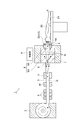
図1に示されるように、第1の実施形態に係る中性子捕捉療法装置1は、ホウ素中性子捕捉療法(BNCT:Boron Neutron Capture Therapy)を用いたがん治療などを行うために用いられる装置であり、ホウ素(10B)が投与された患者50の腫瘍Fへ中性子線Nを照射する。
[First Embodiment]
As shown in FIG. 1, the neutron capture therapy apparatus 1 according to the first embodiment is an apparatus used for performing cancer treatment using boron neutron capture therapy (BNCT). The neutron beam N is irradiated to the tumor F of the
中性子捕捉療法装置1は、サイクロトロン2を備えている。サイクロトロン2は、陰イオン等の荷電粒子を加速して、荷電粒子線Rを作り出す加速器である。このサイクロトロン2は、例えば、ビーム半径40mm、60kW(=30MeV×2mA)の荷電粒子線Rを生成する能力を有している。なお、加速器は、サイクロトロンに限られず、シンクロトロンやシンクロサイクロトロン、ライナックなどであってもよい。
The neutron capture therapy apparatus 1 includes a
サイクロトロン2から出射された荷電粒子線Rは、ビームダクト3を通り、ターゲット6へ向かって進行する。このビームダクト3に沿って複数の四極電磁石4及び走査電磁石5が設けられている。複数の四極電磁石4は、例えば電磁石を用いて荷電粒子線Rのビーム軸調整を行うものである。また、走査電磁石5は、荷電粒子線Rを走査し、ターゲット6に対する荷電粒子線Rの照射制御を行うものである。この走査電磁石5は、荷電粒子線Rのターゲット6に対する照射位置を制御する。
The charged particle beam R emitted from the
中性子捕捉療法装置1は、荷電粒子線Rをターゲット6に照射することにより中性子線Nを発生させ、患者50に向かって出射する。中性子捕捉療法装置1は、ターゲット6、遮蔽体7、減速材8、コリメータ9、及び中性子線量測定装置10を備えている。
The neutron capture therapy apparatus 1 generates a neutron beam N by irradiating the
また、中性子捕捉療法装置1は、制御部(算出手段)Sを備えている。制御部Sは、CPU[Central Processing Unit]、ROM[Read Only Memory]、RAM[Random Access Memory]等からなる電子制御ユニットであり、中性子捕捉療法装置1を総合的に制御する。 Further, the neutron capture therapy apparatus 1 includes a control unit (calculation means) S. The control unit S is an electronic control unit including a CPU [Central Processing Unit], a ROM [Read Only Memory], a RAM [Random Access Memory], and the like, and comprehensively controls the neutron capture therapy apparatus 1.
制御部Sは、ターゲット6に照射される荷電粒子線Rの電流値(すなわち、電荷、照射線量率)をリアルタイムで測定する電流モニタMを備えている。電流モニタMとしては、例えば、荷電粒子線Rに影響を与えずに測定可能な非破壊型のDCCT[Direct Current Current Transformer]が用いられる。 The control unit S includes a current monitor M that measures the current value of the charged particle beam R irradiated to the target 6 (that is, the charge and the irradiation dose rate) in real time. As the current monitor M, for example, a non-destructive type DCCT [Direct Current Current Transformer] that can be measured without affecting the charged particle beam R is used.
ターゲット6は、荷電粒子線Rの照射を受けて中性子線Nを発生するものである。ここでのターゲット6は、例えば、ベリリウム(Be)やリチウム(Li)、タンタル(Ta)、タングステン(W)により形成され、直径160mmの円板状を成している。
The
遮蔽体7は、発生させた中性子線N、及び当該中性子線Nの発生に伴って生じたガンマ線等を外部へ放出されないよう遮蔽するものである。減速材8は、中性子線Nのエネルギーを減速(減衰)させるものであり、遮蔽体7の内部に設けられている。減速材8は、中性子線Nに含まれる速中性子を主に減速させる第1の減速材8Aと、中性子線Nに含まれる熱外中性子を主に減速させる第2の減速材8Bと、からなる積層構造を有している。
The
コリメータ9は、中性子線Nの照射野(中性子線Nの進行方向に直交する平面における照射範囲)を整形するものであり、中性子線Nが通過する開口9aを有している。ターゲット6で発生した中性子線Nは、減速材8を通り抜けた後、このコリメータ9の開口9aを一部が通過することで所定の照射野に整形される。
The collimator 9 shapes the irradiation field of the neutron beam N (irradiation range in a plane orthogonal to the traveling direction of the neutron beam N), and has an
中性子線量測定装置10は、治療台51上の患者50に照射される中性子線Nの線量及び線量分布を測定する装置である。ここで、図2は中性子線量測定装置10を示す図である。図2に示す中性子線量測定装置10は、中性子線Nの入射により発光するシンチレータ部20と、シンチレータ部20で生じた光を伝達するライトガイド部30と、ライトガイド部30により伝達された光を検出して電気信号を出力する光検出部40と、を備えている。
The neutron
シンチレータ部20は、入射した中性子線Nを光に変換する蛍光体である。シンチレータ部20は、コリメータ9の下流側(中性子線Nの進行方向における下流側)に配置されている。シンチレータ部20は、入射した中性子線Nの線量に応じて内部結晶が励起状態となり、シンチレーション光を発生させる。
The
シンチレータ部20は、円環形状に形成されており、その中央に開口Tを有している。開口Tは、コリメータ9の開口9aより大きく形成されている。コリメータ9の開口9aを通過した中性子線Nは、この開口Tを通過して患者50へ向かう。図2に開口Tを通過する中性子線Nの進行方向NFを示す。進行方向NFは、開口Tを通過する中性子線Nの主たる進行方向を示しており、実際には様々な角度に進む中性子線Nが存在する。なお、特許請求の範囲における中性子線の進行方向とは、中性子線Nの主たる進行方向を意味している。中性子線Nの主たる進行方向とは、ターゲット6に照射される際の荷電粒子線Rの進行方向(正確には、走査電磁石5で何も走査しなかったときの荷電粒子線Rの進行方向)である。
The
ライトガイド部30は、シンチレータ部20で生じた光を伝達する部材である。ライトガイド部30は、例えば、フレキシブルな光ファイバーの束などから構成されている。
The
光検出部40は、ライトガイド部30を通じてシンチレータ部20で生じた光を検出し、電気信号を出力するものである。光検出部40には、例えば光電子増倍管や光電管など各種の光検出機器を採用することができる。光検出部40は、制御部Sと接続されており、光検出時に電子信号を制御部Sに出力する。
The
図3は、開口Tを通過する中性子線Nを説明するための図である。図3に示されるように、中性子線Nは、コリメータ9の開口9aを通り抜けて照射野が整形された後も、進行と共に径方向(進行方向NFと直交する方向)に拡散するため、中性子線Nの一部はシンチレータ部20に設けられた開口Tを通り抜けずにシンチレータ部20へと入射する。シンチレータ部20に中性子線Nが入射し、シンチレータ部20の内部結晶が励起状態になると、中性子線Nの線量に応じた光が生じ、ライトガイド部30を通じて光検出部40に光が検出される。光検出部40は、検出した光に応じて電気信号を制御部Sに出力する。
FIG. 3 is a diagram for explaining the neutron beam N passing through the opening T. FIG. As shown in FIG. 3, neutrons N, after the irradiation field is shaped through an
続いて、図2を参照してシンチレータ部20、ライトガイド部30、及び光検出部40の構成について説明する。図2に示されるように、シンチレータ部20は、4つのシンチレータ21〜24から構成されている。シンチレータ21〜24は、それぞれが開口Tを通過する中性子線Nの進行方向NFから見て円環形状をなす部材である。シンチレータ21〜24は、進行方向NFに直交する平面内で同心円状に配置されている。なお、円環形状は正円の環形状に限られず、長円や楕円等の環形状も含まれる。
Next, the configuration of the
シンチレータ21〜24は、第1のシンチレータ21、第2のシンチレータ22、第3のシンチレータ23、第4のシンチレータ24の順に大きな半径を有している。なお、シンチレータ21〜24の径方向の厚さは、同じであってもよく、異なっていてもよい。シンチレータ21〜24には、6Liガラスシンチレータ、LiCAFシンチレータ、6LiFを塗布したプラスチックシンチレータ、6LiF/ZnSシンチレータ等を採用できる。なお、シンチレータ21〜24は、必ずしも同種のシンチレータである必要はない。
The
第1のシンチレータ21は、最も半径の円環形状の小さいシンチレータである。この第1のシンチレータ21の中央に開口Tが形成されている。第1のシンチレータ21は、ライトガイド部30を構成する第1のライトガイド31と接続されている。この第1のライトガイド31は、光検出部40を構成する第1の光検出器41と接続されている。中性子線Nが第1のシンチレータ21に入射すると、第1のシンチレータ21内で生じた光が第1のライトガイド31を通じて第1の光検出器41に検出され、電気信号が制御部Sに出力される。
The
第2のシンチレータ22は、第1のシンチレータ21を外側から囲むように設けられた円環形状のシンチレータである。第2のシンチレータ22は、第1のシンチレータ21の外周に沿って配置されており、その内周面は第1のシンチレータ21の外周面と接している。第2のシンチレータ22と第1のシンチレータ21との間は遮光されており、第1のシンチレータ21の光は第2のシンチレータ22に侵入しない。なお、第1のシンチレータ21及び第2のシンチレータ22は、互いに離間して所定の隙間を形成するように設けられていてもよい。
The
第2のシンチレータ22は、ライトガイド部30を構成する第2のライトガイド32と接続されている。この第2のライトガイド32は、光検出部40を構成する第2の光検出器42と接続されている。中性子線Nが第2のシンチレータ22に入射すると、第2のシンチレータ22内で生じた光が第2のライトガイド32を通じて第2の光検出器42に検出され、電気信号が制御部Sに出力される。第1のシンチレータ21及び第2のシンチレータ22は、それぞれ特許請求の範囲に記載の第1の中性子検出器及び第2の中性子検出器に相当する。
The
第3のシンチレータ23は、第2のシンチレータ22を外側から囲むように設けられた円環形状のシンチレータである。第3のシンチレータ23は、第2のシンチレータ22の外周に沿って配置されており、その内周面は第2のシンチレータ22の外周面と接している。第3のシンチレータ23と第2のシンチレータ22との間は遮光されており、第2のシンチレータ22の光は第3のシンチレータ23に侵入しない。なお、第2のシンチレータ22及び第3のシンチレータ23は、互いに離間して所定の隙間を形成するように設けられていてもよい。
The
第3のシンチレータ23は、ライトガイド部30を構成する第3のライトガイド33と接続されている。この第3のライトガイド33は、光検出部40を構成する第3の光検出器43と接続されている。中性子線Nが第3のシンチレータ23に入射すると、第3のシンチレータ23内で生じた光が第3のライトガイド33を通じて第3の光検出器43に検出され、電気信号が制御部Sに出力される。
The
同様に、第4のシンチレータ24は、第3のシンチレータ23を外側から囲むように設けられた最も半径の大きい円環形状のシンチレータである。第4のシンチレータ24は、第4のシンチレータ24の外周に沿って配置されており、その内周面は第4のシンチレータ24の外周面と接している。第4のシンチレータ24と第3のシンチレータ23との間は遮光されており、第3のシンチレータ23の光は第4のシンチレータ24に侵入しない。なお、第3のシンチレータ23及び第4のシンチレータ24は、互いに離間して所定の隙間を形成するように設けられていてもよい。
Similarly, the
第4のシンチレータ24は、ライトガイド部30を構成する第4のライトガイド34と接続されている。この第4のライトガイド34は、光検出部40を構成する第4の光検出器44と接続されている。中性子線Nが第4のシンチレータ24に入射すると、第4のシンチレータ24内で生じた光が第4のライトガイド34を通じて第4の光検出器44に検出され、電気信号が制御部Sに出力される。
The
このように構成された中性子線量測定装置10では、開口Tの周囲のシンチレータ21〜24に入射した中性子線Nの中性子数を検出し、各シンチレータ21〜24の半径(開口Tの中心からの距離)と各シンチレータ21〜24が検出した中性子数の関係に基づいて、開口Tを通過した中性子線Nの線量及び線量分布を算出(測定)する。
In the
なお、シンチレータ21〜24は、互いに取り外し可能に構成されている。例えば、開口Tを大きくしたい場合には、第1のシンチレータ21を外すことで、第2のシンチレータ22の内側を新たな開口Tとすることができる。その他、シンチレータの数は四つに限られず、二つ以上であればよく、五つ以上設けてもよい。
The
図4は、開口Tを通過した中性子線Nの線量の算出(測定)を説明するためのグラフである。図4に示すグラフの縦軸は中性子数を示し、横軸はシンチレータの半径を示している。図4において、P1は第1のシンチレータ21の検出結果、P2は第1のシンチレータ22の検出結果、P3は第1のシンチレータ23の検出結果、P4は第1のシンチレータ24の検出結果である。また、開口Tを通過した中性子線Nの中性子数の算出結果をQ1,Q2として示す。
FIG. 4 is a graph for explaining the calculation (measurement) of the dose of the neutron beam N that has passed through the opening T. The vertical axis of the graph shown in FIG. 4 indicates the number of neutrons, and the horizontal axis indicates the radius of the scintillator. In FIG. 4, P1 is the detection result of the
図4に示されるように、中性子線Nは、ビーム径の中心に近いほど中性子数が多くなり、ビーム径の中心から離れるほど中性子数が少なくなる。そこで、制御部Sでは、シンチレータ21〜24の検出結果P1〜P4に基づき、検出された中性子数と開口Tの中心(ビーム径の中心)からの距離に関するフィット関数を導き、このフィット関数を用いて開口Tを通過した中性子線Nの中性子数の算出結果Q1,Q2を取得する。制御部Sは、算出結果Q1,Q2に基づいて、開口Tを通過した中性子線Nの線量及び線量分布(開口Tの中心からの距離に対する中性子線Nの線量の分布)を得る。
As shown in FIG. 4, the neutron beam N has a greater number of neutrons as it is closer to the center of the beam diameter, and a smaller number of neutrons the further away from the center of the beam diameter. Therefore, the control unit S derives a fit function related to the number of detected neutrons and the distance from the center of the aperture T (the center of the beam diameter) based on the detection results P1 to P4 of the
なお、開口Tを通過した中性子線Nの線量及び線量分布の算出手法は、上述したものに限られない。例えば、周知の数学的手法により、シンチレータ21〜24の検出結果P1〜P4から算出結果Q1,Q2や線量等を求めてもよい。また、シンチレータ21〜24の検出結果P1〜P4と開口Tを通過した中性子線Nの線量等の対応関係を示すデータマップを制御部Sが予め記憶しており、このデータマップを利用して、開口Tを通過した中性子線Nの線量を算出してもよい。
Note that the method of calculating the dose and dose distribution of the neutron beam N that has passed through the opening T is not limited to the above-described method. For example, the calculation results Q1, Q2, the dose, and the like may be obtained from the detection results P1 to P4 of the
次に、以上説明した第1の実施形態に係る中性子捕捉療法装置1(中性子線量測定装置10)の作用効果について説明する。 Next, the effect of the neutron capture therapy apparatus 1 (neutron dose measuring apparatus 10) according to the first embodiment described above will be described.
第1の実施形態に係る中性子捕捉療法装置1によれば、中性子線Nが通過する開口Tを有する第1のシンチレータ21を外側から囲むようにシンチレータ22〜24が設けられているので、各シンチレータ21〜24の半径と各シンチレータ21〜24が検出した中性子数の関係から、開口Tを通過した中性子線Nの線量及び線量分布を算出(測定)することが可能となる。しかも、この中性子捕捉療法装置1では、中性子線Nの線量及び線量分布を測定するために、中性子線Nの照射を止める必要がなく、照射中に中性子線Nの線量の測定をリアルタイムで行うことができる。更に、この中性子捕捉療法装置1によれば、患者50の腫瘍Fに照射される中性子線Nはシンチレータ21〜24に妨げられることなく開口Tを通過するので、シンチレータ21〜24の配置による中性子線Nの照射精度の低下を抑えることができる。
According to the neutron capture therapy apparatus 1 according to the first embodiment, the
また、この中性子線量測定装置1によれば、中性子線Nが通過する開口Tをシンチレータ20が有する構成とすることで、中性子線Nの照射野の外側に一点,二点の中性子検出器を配置して測定する場合と比べて、中性子線Nの線量の測定精度を大きく向上させることができる。
Further, according to the neutron dose measuring apparatus 1, the
また、この中性子捕捉療法装置1によれば、シンチレータ21〜24のそれぞれが中性子線Nの進行方向NFから見て開口Tの中心から所定の半径を有する円環形状をなしているので、各シンチレータ21〜24の半径(開口Tの中心からの距離)と各シンチレータ21〜24の検出結果P1〜P4の関係がシンプルとなりフィット関数等を導きやすく、開口Tを通過した中性子線Nの線量及び線量分布の測定に関する演算を容易にすることができる。
Further, according to the neutron capture therapy apparatus 1, since each of the
更に、この中性子捕捉療法装置1によれば、シンチレータ21〜24がコリメータ9の下流側に配置されているので、シンチレータ21〜24がコリメータ9の上流側に配置されている場合と比べて、測定後にコリメータ9による照射野の整形で中性子線Nの線量が低減することがない上、より患者50に近い位置で中性子線Nの線量を測定できる。その結果、患者50に照射される中性子線Nの線量及び線量分布を精度良く測定することができる。また、この中性子捕捉療法装置1では、シンチレータ21〜24がコリメータ9の下流側に配置されているので、シンチレータ21〜24がコリメータ9の上流側に配置されている場合と比べて、中性子線Nがシンチレータ21〜24に過剰に入射することが避けられる。
Furthermore, according to this neutron capture therapy apparatus 1, since the
[第2の実施形態]
図5に示されるように、第2の実施形態に係る中性子捕捉療法装置は、第1の実施形態に係る中性子捕捉療法装置1と比べて、中性子線量測定装置におけるシンチレータ部60の構成が異なっている。
[Second Embodiment]
As shown in FIG. 5, the neutron capture therapy apparatus according to the second embodiment differs from the neutron capture therapy apparatus 1 according to the first embodiment in the configuration of the
図5に示す第2の実施形態に係るシンチレータ部60は、中央に四角形状の開口Tを有する井桁形状(フレーム形状)に構成されている。シンチレータ部60は、第1のシンチレータ70、第2のシンチレータ80、第3のシンチレータ90、第4のシンチレータ100を有している。これらのシンチレータ70,80,90,100は、それぞれ棒状のシンチレータ素子が井桁形状に組まれて構成されている。シンチレータ70,80,90,100は、内側(開口T側)から外側に向かって、第1のシンチレータ70、第2のシンチレータ80、第3のシンチレータ90、第4のシンチレータ100の順に設けられている。
The
第1のシンチレータ70は、4つの棒状のシンチレータ素子(検出素子)71〜74によって井桁形状に構成されており、中央の開口Tを形成している。具体的には、第1のシンチレータ素子71及び第2のシンチレータ素子72は、所定方向(例えば水平方向)に延在して互いに平行に配置されており、第3のシンチレータ素子73及び第4のシンチレータ素子74は、所定方向に直交する方向(例えば鉛直方向)に延在して互いに平行に配置されている。すなわち、シンチレータ素子71〜74は、四角形状の開口Tの各辺を形成している。
The
シンチレータ素子71〜74には、それぞれライトガイド111〜114が接続されている。ライトガイド111〜114は、図示しない4つの光検出器にそれぞれ接続されており、シンチレータ素子71〜74で生じた光はライトガイド111〜114を通じて光検出器に伝達される。 Light guides 111 to 114 are connected to the scintillator elements 71 to 74, respectively. The light guides 111 to 114 are connected to four photodetectors (not shown), and the light generated by the scintillator elements 71 to 74 is transmitted to the photodetectors through the light guides 111 to 114.
第2のシンチレータ80は、井桁形状の第1のシンチレータ70を外側から囲むように設けられている。第2のシンチレータ80は、4つの棒状のシンチレータ素子(検出素子)81〜84によって井桁形状に構成されており、これらのシンチレータ素子81〜84は第1のシンチレータ70を構成するシンチレータ素子71〜74の外側(開口Tと反対側)に配置されている。
The
具体的には、第2のシンチレータ80における第1のシンチレータ素子81は、第1のシンチレータ素子71の外側に沿って配置されており、第2のシンチレータ素子82は、第2のシンチレータ素子72の外側に沿って配置されている。同様に、第3のシンチレータ素子83は、第3のシンチレータ素子73の外側に沿って配置されており、第4のシンチレータ素子84は、第4のシンチレータ素子74の外側に沿って配置されている。
Specifically, the
シンチレータ素子81〜84には、それぞれライトガイド121〜124が接続されている。ライトガイド121〜124は、図示しない4つの光検出器にそれぞれ接続されており、シンチレータ素子81〜84で生じた光はライトガイド121〜124を通じて光検出器に伝達される。第1のシンチレータ70及び第2のシンチレータ80は、それぞれ特許請求の範囲に記載の第1の中性子検出器及び第2の中性子検出器に相当する。
Light guides 121 to 124 are connected to the
また、第3のシンチレータ90は、井桁形状の第2のシンチレータ80を外側から囲むように設けられている。第3のシンチレータ90は、4つの棒状のシンチレータ素子(検出素子)91〜94によって井桁形状に構成されており、これらのシンチレータ素子91〜94は第2のシンチレータ80を構成するシンチレータ素子81〜84の外側(開口Tと反対側)に配置されている。
In addition, the
シンチレータ素子91〜94には、それぞれライトガイド131〜134が接続されている。ライトガイド131〜134は、図示しない4つの光検出器にそれぞれ接続されており、シンチレータ素子91〜94で生じた光はライトガイド131〜134を通じて光検出器に伝達される。 Light guides 131 to 134 are connected to the scintillator elements 91 to 94, respectively. The light guides 131 to 134 are respectively connected to four photodetectors (not shown), and light generated by the scintillator elements 91 to 94 is transmitted to the photodetectors through the light guides 131 to 134.
同様に、第4のシンチレータ100は、井桁形状の第3のシンチレータ90を外側から囲むように設けられ、最も外側に位置するシンチレータである。第4のシンチレータ100は、4つの棒状のシンチレータ素子(検出素子)101〜104によって井桁形状に構成されており、これらのシンチレータ素子101〜104は第3のシンチレータ90を構成するシンチレータ素子91〜94の外側(開口Tと反対側)に配置されている。
Similarly, the
シンチレータ素子101〜104には、それぞれライトガイド141〜144が接続されている。ライトガイド141〜144は、図示しない4つの光検出器にそれぞれ接続されており、シンチレータ素子101〜104で生じた光はライトガイド141〜144を通じて光検出器に伝達される。
Light guides 141 to 144 are connected to the
また、第2の実施形態に係るシンチレータ部60は、各シンチレータ70,80,90、100を所定方向に移動させるリニアモータ(移動手段)151〜154を備えている。リニアモータ151〜154は、各シンチレータ70,80,90、100を中性子線Nの進行方向NFに直交する方向に移動させるものである。
The
具体的には、第1のリニアモータ151は、第1のシンチレータ素子71,81,91,101を矢印A1の示す方向に一体的に移動させるものである。第2のリニアモータ152は、第2のシンチレータ素子72,82,92,102を矢印A2の示す方向に一体的に移動させるものである。第3のリニアモータ153は、第3のシンチレータ素子73,83,93,103を矢印A3の示す方向に一体的に移動させるものである。第4のリニアモータ154は、第4のシンチレータ素子74,84,94,104を矢印A4の示す方向に一体的に移動させるものである。なお、シンチレータ部60は、各シンチレータ素子を直線移動させるためのリニアガイドを備えていてもよい。
Specifically, the first
以上説明した第2の実施形態に係る中性子捕捉療法装置によれば、開口Tを形成する第1のシンチレータ70を外側から囲むようにシンチレータ80,90、100が設けられているので、各シンチレータ70,80,90、100における開口Tの中心からの距離と各シンチレータ70,80,90、100が検出する中性子数の関係から、開口Tを通過した中性子線Nの線量及び線量分布を測定することが可能となる。しかも、この中性子捕捉療法装置では、中性子線Nの線量及び線量分布を測定するために、中性子線Nの照射を止める必要がなく、照射中に中性子線Nの線量の測定をリアルタイムで行うことができる。更に、この中性子捕捉療法装置によれば、患者50の腫瘍Fに照射される中性子線Nはシンチレータ70,80,90、100に妨げられることなく開口Tを通過するので、シンチレータ70,80,90、100の配置による中性子線Nの照射精度の低下を抑えることができる。
According to the neutron capture therapy apparatus according to the second embodiment described above, since the
また、この中性子捕捉療法装置によれば、シンチレータ部60を四角形状の開口Tを有する井桁形状とすることで構成を簡素化することができ、棒状のシンチレータ素子を組み合わせて容易にシンチレータ部60を製造することができる。
Further, according to this neutron capture therapy apparatus, the configuration can be simplified by making the
また、この中性子捕捉療法装置によれば、開口Tを形成する複数のシンチレータ素子からシンチレータ70,80,90、100を構成しているので、シンチレータ素子を中性子線Nの進行方向NFと直交する方向に移動させることで、開口Tの大きさを調整することができる。これにより、患者50の腫瘍Fに合わせて異なる大きさの照射野を形成する際に、開口Tを適切に調整することで、中性子線Nの照射野を妨げることなく十分な精度で線量及び線量分布の測定を行うことができる。
Further, according to the neutron capture therapy apparatus, since constitute a
以上、本発明の好適な実施形態について説明したが、本発明は上述した実施形態に限定されるものではない。例えば、中性子検出器はシンチレータである必要はなく、電離箱であってもよい。また、第1の実施形態に係るシンチレータ部の形状は、円環形状ではなく、四角形枠状や三角形枠状を含む多角形枠状(フレーム形状)であってもよい。中心の開口の形状も円形状の他、多角形状やその他の形状とすることもできる。また、シンチレータ部を構成する複数のシンチレータは全てが円環形状や多角形枠状及び井桁形状を含むフレーム形状で統一されている必要はなく、これらが混在していてもよい。すなわち、円環形状のシンチレータの外側を四角形状のシンチレータが囲っていてもよく、その逆であってもよい。 As mentioned above, although preferred embodiment of this invention was described, this invention is not limited to embodiment mentioned above. For example, the neutron detector need not be a scintillator but may be an ionization chamber. Further, the shape of the scintillator portion according to the first embodiment may be a polygonal frame shape (frame shape) including a quadrangular frame shape or a triangular frame shape instead of an annular shape. The shape of the central opening may be a polygonal shape or other shapes in addition to a circular shape. Further, the scintillators constituting the scintillator portion do not have to be unified in a frame shape including an annular shape, a polygonal frame shape, and a cross beam shape, and these may be mixed. That is, a quadrangular scintillator may surround the outside of the annular scintillator, and vice versa.
また、シンチレータが円環形状をなす場合であっても、シンチレータが複数のシンチレータ素子(例えば弧形状のシンチレータ素子)から構成されていてもよい。この場合、開口を形成するシンチレータ素子の少なくとも一つを中性子線の進行方向に直交する方向に移動可能とすることで、開口の大きさを調整することができる。なお、必ずしもシンチレータ素子を移動させるリニアモータを備える必要はなく、手作業で調整してもよい。また、必ずしもシンチレータ素子の全てを移動可能に構成する必要はなく、開口を形成する少なくとも一つのシンチレータ素子が移動可能に構成されていればよい。 Even when the scintillator has an annular shape, the scintillator may be composed of a plurality of scintillator elements (for example, arc-shaped scintillator elements). In this case, the size of the opening can be adjusted by making it possible to move at least one of the scintillator elements forming the opening in a direction orthogonal to the traveling direction of the neutron beam. Note that it is not always necessary to provide a linear motor for moving the scintillator element, and it may be adjusted manually. In addition, it is not always necessary to configure all of the scintillator elements to be movable, as long as at least one scintillator element forming the opening is configured to be movable.
1…中性子捕捉療法装置 2…サイクロトロン 3…ビームダクト 4…四極電磁石 5…走査電磁石 6…ターゲット 7…遮蔽体 8…減速材 9…コリメータ 9a…開口 10…中性子線量測定装置 20…シンチレータ部 21…第1のシンチレータ(第1の中性子検出器) 22…第2のシンチレータ(第2の中性子検出器) 23…第3のシンチレータ 24…第4のシンチレータ 30…ライトガイド部 31…第1のライトガイド 32…第2のライトガイド 33…第3のライトガイド 34…第4のライトガイド 40…光検出部 41…第1の光検出器 42…第2の光検出器 43…第3の光検出器 44…第4の光検出器 50…患者 51…治療台 60…シンチレータ部 70…第1のシンチレータ(第1の中性子検出器) 71,81,91,101…第1のシンチレータ素子(検出素子) 72,82,92,102…第2のシンチレータ素子(検出素子) 73,83,93,103…第3のシンチレータ素子(検出素子) 74,84,94,104…第4のシンチレータ素子(検出素子) 80…第2のシンチレータ(第2の中性子検出器) 90…第3のシンチレータ 100…第4のシンチレータ F…腫瘍 N…中性子線 NF…進行方向 R…荷電粒子線 S…制御部(算出手段) T…開口
DESCRIPTION OF SYMBOLS 1 ... Neutron
Claims (6)
中性子線が通過する開口を有する第1の中性子検出器と、
前記第1の中性子検出器を外側から囲むように設けられた第2の中性子検出器と、
前記第1の中性子検出器の検出結果及び前記第2の中性子検出器の検出結果に基づいて、前記開口を通過した中性子線の線量を算出する算出手段と、
を備える中性子線量測定装置。 A neutron dosimetry device that measures the dose of neutron radiation,
A first neutron detector having an aperture through which a neutron beam passes;
A second neutron detector provided to surround the first neutron detector from the outside;
A calculation means for calculating a dose of neutron beam that has passed through the opening based on a detection result of the first neutron detector and a detection result of the second neutron detector;
A neutron dosimetry apparatus comprising:
前記複数の検出素子のうち少なくとも一つは、前記開口を通過する中性子線の進行方向と直交する方向に移動可能である、請求項1〜3の何れか1項に記載の中性子線量測定装置。 The first neutron detector has a plurality of detection elements forming the opening,
The neutron dosimetry apparatus according to any one of claims 1 to 3, wherein at least one of the plurality of detection elements is movable in a direction orthogonal to a traveling direction of a neutron beam passing through the opening.
前記中性子線量測定装置の前記第1の中性子検出器及び前記第2の中性子検出器は、前記コリメータの下流側に配置されている、請求項5に記載の中性子捕捉療法装置。
A collimator for shaping the neutron radiation field;
The neutron capture therapy apparatus according to claim 5, wherein the first neutron detector and the second neutron detector of the neutron dosimetry apparatus are arranged on the downstream side of the collimator.
Priority Applications (1)
| Application Number | Priority Date | Filing Date | Title |
|---|---|---|---|
| JP2013064654A JP2014190754A (en) | 2013-03-26 | 2013-03-26 | Neutron dosimetry device and neutron capture therapy device |
Applications Claiming Priority (1)
| Application Number | Priority Date | Filing Date | Title |
|---|---|---|---|
| JP2013064654A JP2014190754A (en) | 2013-03-26 | 2013-03-26 | Neutron dosimetry device and neutron capture therapy device |
Publications (1)
| Publication Number | Publication Date |
|---|---|
| JP2014190754A true JP2014190754A (en) | 2014-10-06 |
Family
ID=51837154
Family Applications (1)
| Application Number | Title | Priority Date | Filing Date |
|---|---|---|---|
| JP2013064654A Pending JP2014190754A (en) | 2013-03-26 | 2013-03-26 | Neutron dosimetry device and neutron capture therapy device |
Country Status (1)
| Country | Link |
|---|---|
| JP (1) | JP2014190754A (en) |
Cited By (6)
| Publication number | Priority date | Publication date | Assignee | Title |
|---|---|---|---|---|
| JP2017009393A (en) * | 2015-06-19 | 2017-01-12 | 株式会社東芝 | Neutron measurement device, neutron measurement method, and treatment apparatus for boron neutron capture therapy |
| US9977138B2 (en) | 2015-09-09 | 2018-05-22 | Yasu Medical Imaging Technology Co., Ltd. | Thermal neutron detecting device, scintillator unit, and thermal neutron detecting system |
| CN108853751A (en) * | 2017-05-12 | 2018-11-23 | 南京中硼联康医疗科技有限公司 | Photon emits detection device and the boron neutron capture treatment system with it |
| WO2019198125A1 (en) | 2018-04-09 | 2019-10-17 | 公立大学法人大阪府立大学 | Electromagnetic radiation detection device and method |
| US10568964B2 (en) | 2016-09-23 | 2020-02-25 | Sumitomo Heavy Industries, Ltd. | Neutron capture therapy system and therapy planning system for neutron capture therapy |
| KR20200052099A (en) * | 2018-11-06 | 2020-05-14 | 한국원자력의학원 | Collimator for Neutron Capture Therapy System |
-
2013
- 2013-03-26 JP JP2013064654A patent/JP2014190754A/en active Pending
Cited By (9)
| Publication number | Priority date | Publication date | Assignee | Title |
|---|---|---|---|---|
| JP2017009393A (en) * | 2015-06-19 | 2017-01-12 | 株式会社東芝 | Neutron measurement device, neutron measurement method, and treatment apparatus for boron neutron capture therapy |
| US9977138B2 (en) | 2015-09-09 | 2018-05-22 | Yasu Medical Imaging Technology Co., Ltd. | Thermal neutron detecting device, scintillator unit, and thermal neutron detecting system |
| US10568964B2 (en) | 2016-09-23 | 2020-02-25 | Sumitomo Heavy Industries, Ltd. | Neutron capture therapy system and therapy planning system for neutron capture therapy |
| CN108853751A (en) * | 2017-05-12 | 2018-11-23 | 南京中硼联康医疗科技有限公司 | Photon emits detection device and the boron neutron capture treatment system with it |
| WO2019198125A1 (en) | 2018-04-09 | 2019-10-17 | 公立大学法人大阪府立大学 | Electromagnetic radiation detection device and method |
| KR20200123253A (en) | 2018-04-09 | 2020-10-28 | 코우리츠 다이가꾸 호우진 오사카 | Electron radiation detection apparatus and method |
| US11194060B2 (en) | 2018-04-09 | 2021-12-07 | University Public Corporation Osaka | Electromagnetic radiation detector and method |
| KR20200052099A (en) * | 2018-11-06 | 2020-05-14 | 한국원자력의학원 | Collimator for Neutron Capture Therapy System |
| KR102118077B1 (en) | 2018-11-06 | 2020-06-02 | 한국원자력의학원 | Collimator for Neutron Capture Therapy System |
Similar Documents
| Publication | Publication Date | Title |
|---|---|---|
| JP5996470B2 (en) | Neutron capture therapy device | |
| TWI520758B (en) | Neutron capture therapy apparatus and method for measuring the neutron beam | |
| JP6052933B2 (en) | Neutron beam detection device and neutron capture therapy device | |
| JP2014190754A (en) | Neutron dosimetry device and neutron capture therapy device | |
| US10441815B2 (en) | Neutron capture therapy system and gamma ray detector for neutron capture therapy | |
| JP6699004B2 (en) | Neutron capture therapy system and method of controlling neutron capture therapy system | |
| JP6938627B2 (en) | Neutron capture therapy system | |
| TWI795997B (en) | Neutron capture therapy equipment and calibration method thereof | |
| JP2013061295A (en) | Neutron ray irradiation device | |
| TWI666464B (en) | Neutron beam detection system and setting method of neutron beam detection system | |
| JP6613464B2 (en) | Neutron beam detector | |
| JP2013062193A (en) | Neutron beam irradiation device | |
| JP6320761B2 (en) | Neutron beam detection device and neutron capture therapy device | |
| JP7021989B2 (en) | Neutron capture therapy system and neutron detector | |
| JP6532008B2 (en) | Phantom device for neutron beam measurement | |
| JP6875265B2 (en) | Neutron beam detector | |
| JP2017176438A (en) | Neutron capture therapy system and gamma ray reaction element | |
| JP7248470B2 (en) | Neutron detector | |
| RU2629948C1 (en) | Device for determining sizes of focus spot of accelerator brake radiation | |
| JP2022078886A (en) | Particle beam monitoring system, particle beam monitoring method, and particle beam treatment system | |
| JP2016038273A (en) | Use time measuring device for scintillators, use time measuring method for scintillators, and neutron capture therapy system |