JP2014190436A - Electric actuator for vehicle - Google Patents
Electric actuator for vehicle Download PDFInfo
- Publication number
- JP2014190436A JP2014190436A JP2013066612A JP2013066612A JP2014190436A JP 2014190436 A JP2014190436 A JP 2014190436A JP 2013066612 A JP2013066612 A JP 2013066612A JP 2013066612 A JP2013066612 A JP 2013066612A JP 2014190436 A JP2014190436 A JP 2014190436A
- Authority
- JP
- Japan
- Prior art keywords
- electric motor
- electric actuator
- sleeve
- brake
- rotor
- Prior art date
- Legal status (The legal status is an assumption and is not a legal conclusion. Google has not performed a legal analysis and makes no representation as to the accuracy of the status listed.)
- Granted
Links
Images


Abstract
Description
本発明は、車両に積載された可動部品あるいは作業機器などを駆動するため、車両に装備される電動アクチュエータに関するものである。 The present invention relates to an electric actuator mounted on a vehicle in order to drive a movable part or work equipment mounted on the vehicle.
車両には、様々な可動部品あるいは可動部を備えた作業機器を搭載することが多い。例えば、貨物輸送用の車両であるトラックの荷台には、可動式の屋根を設置して荷台の側方からも貨物の積み降ろしを可能としたウイングボディと呼ばれる荷台ある。ウイングボディでは、荷台の長手方向の中心線に沿って左右に分割された屋根パネルが側面パネルと一体となってウイングを構成しており、左右両側のウイングは、荷台の屋根中央のヒンジを中心としてアクチュエータにより跳ね上げ式に開閉される。ウイング開閉用のアクチュエータとしては、通常、油圧で作動する油圧シリンダが用いられる。 In many cases, vehicles are equipped with various movable parts or work equipment having movable parts. For example, a truck bed, which is a vehicle for freight transportation, has a cargo bed called a wing body that has a movable roof and can be loaded and unloaded from the side of the bed. In the wing body, the roof panel divided into right and left along the center line in the longitudinal direction of the loading platform forms a wing integrally with the side panel, and the left and right wings are centered on the hinge at the center of the roof of the loading platform. Is opened and closed in a flip-up manner by the actuator. As an actuator for opening and closing the wing, a hydraulic cylinder that operates by hydraulic pressure is usually used.
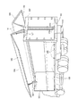
トラックに搭載された一般的なウイングボディの構造を図4に示す。荷台の前部には前面パネル101が、後部には後部フレーム102が配置され、後部フレーム102には観音開き式の後部扉103が取り付けてある。上部には2枚のウイング104が配置されており、これらは、分割された屋根パネル141と左右の側面パネル142の一方とが一体となった断面L字状のものである。荷台の側面の下方には、煽り板105がヒンジ106によって下側に回動可能に取り付けられている。
The structure of a general wing body mounted on a truck is shown in FIG. A
ウイング104を開閉するためのアクチュエータとして、後部フレーム102と左右のウイングの屋根パネル104との間をそれぞれ連結する2個の油圧シリンダ107が設置され、同様な油圧シリンダ107は、前面パネル101のフレーム上部にも設置されている。油圧シリンダ107に供給する作動油を制御してそのロッドを伸長すると、図の実線に示すように、ウイング104が上方に移動して荷台の側面が開放され、油圧シリンダ107のロッドを短縮すると、2点鎖線に示すように、ウイング104の側面パネル142の下端部が煽り板105の上端部に密着し、荷台は閉鎖される。
ウイング104の開閉速度は、その位置に応じて制御されており、開放開始時には、雨水が荷台内部に発生する負圧に巻き込まれて侵入するのを防止するよう、また、ウイング104の閉鎖終了時には、側面パネル142の下端部が衝撃的に煽り板105の上部に当接することのないよう、開閉速度が微速又は緩速となる。こうしたウイングの開閉操作方法及びそのための制御回路は、本出願人の先行出願に係る特許第4416805号公報に開示されている。
As an actuator for opening and closing the
The opening / closing speed of the
図4のように、アクチュエータとして油圧シリンダを用いてウイングを開閉するウイングボディでは、油圧シリンダに油圧を供給する油圧配管を配設する必要があり、油圧発生用の油圧ポンプを駆動する電気モータも必要となって、ウイングの開閉装置全体が複雑化する。これを避けるため、電動アクチュエータ、つまり、電気モータによりねじを形成した軸を回転し、ねじに嵌まり合う部材を直接的に進退させるアクチュエータ、を利用してウイングを開閉することも知られており、一例として、実開平6−61543号公報に示されている。
この公報に記載された電動アクチュエータは、図5に示すとおり、円筒状のハウジング201内にスリーブ状の摺動筒202を嵌め込んだ構造を備え、ハウジング201の端部203がウイングボディの後部フレームに、摺動筒202の端部204が可動部(駆動対象物)であるウイングにそれぞれ連結される。ハウジング201の中心には、ねじを形成したねじ軸205が設置されるとともに、このねじ軸205に嵌まり合うナット部材206が摺動筒202に固着されており、ねじ軸205の正転・逆転により摺動筒202が往復動するよう構成されている。ハウジング201の外側には、ねじ軸205と平行な回転軸を有する電気モータ207取り付けてあり、電気モータ207の回転軸は、減速歯車列208を介してねじ軸205と連結される。
As shown in FIG. 4, in a wing body that opens and closes a wing using a hydraulic cylinder as an actuator, it is necessary to provide a hydraulic pipe for supplying hydraulic pressure to the hydraulic cylinder, and an electric motor that drives a hydraulic pump for generating hydraulic pressure is also provided. As a result, the entire wing opening and closing device is complicated. In order to avoid this, it is also known to open and close the wing using an electric actuator, that is, an actuator that rotates a shaft formed with a screw by an electric motor and directly advances and retracts a member fitted to the screw. As an example, it is shown in Japanese Utility Model Publication No. 6-61543.
As shown in FIG. 5, the electric actuator described in this publication has a structure in which a sleeve-like sliding
上述の電動アクチュエータは、ウイングボディにおけるウイング開閉用のアクチュエータとして用いられるものであるが、当然、電動アクチュエータを他の装置に利用することもできる。貨物輸送用の車両であるトラックには、貨物の積み降ろしを行うための作業機器であるテールゲートを装備するものがあり、電動アクチュエータは、テールゲートにおいて、貨物積載用プラットフォームを荷台と地上との間に昇降させるアクチュエータとしても使用することが可能である。 The electric actuator described above is used as an actuator for opening and closing the wing in the wing body, but the electric actuator can naturally be used for other devices. Some trucks, which are vehicles for freight transportation, are equipped with a tailgate, which is a work device for loading and unloading cargo.Electric actuators have a cargo loading platform between the loading platform and the ground at the tailgate. It can also be used as an actuator that moves up and down in between.
電動アクチュエータは、電気モータの回転を機械的な機構のみにより直接ロッド等の往復動に変換するアクチュエータであり、油圧シリンダのように流体部分を介在させていないので、装置が簡素化されると同時に保守点検等の作業も容易となる。
しかし、電動アクチュエータでは、動力源である電気モータがアクチュエータに一体化されているので、アクチュエータが大型となりコンパクトに構成することが困難である。ことに、車両に装備されるアクチュエータ、例えば、ウイングボディのフレームの上部に装着されるウイング開閉用アクチュエータは、搭載スペースが非常に限定される関係上、小型でコンパクトなものが望ましい。特許文献2に記載の電動アクチュエータでは、電気モータがアクチュエータの横に張り出すように取り付けてあり、ウイングボディに装着すると、その分、荷台の貨物を搭載する部分が削減されることとなる。
An electric actuator is an actuator that converts the rotation of an electric motor directly into a reciprocating motion of a rod or the like only by a mechanical mechanism, and does not intervene a fluid portion like a hydraulic cylinder, so that the apparatus is simplified. Maintenance and inspection work is also facilitated.
However, in the electric actuator, since the electric motor as a power source is integrated with the actuator, it is difficult to make the actuator large and compact. In particular, an actuator mounted on a vehicle, for example, a wing opening / closing actuator mounted on the upper portion of the frame of the wing body is desirably small and compact because the mounting space is very limited. In the electric actuator described in Patent Document 2, the electric motor is attached so as to project to the side of the actuator. When the electric motor is attached to the wing body, the part of the cargo bed on which the cargo is loaded is reduced.
また、電気モータの回転子(電機子)は、重量が大きく慣性モーメントの大きいものが多いため、電気モータの通電を制御するのみでは、アクチュエータの停止位置を正確に制御することが困難である。停止位置の正確な制御には、電気モータにブレーキ機構を組み合わせ、電気モータへの通電が遮断されたときに自動的に制動力を作用させることが有効である。しかし、このような作動を行うブレーキ機構を電動アクチュエータに組み込んだ場合、万一、電気モータや通電系統等に故障が生じたときには、ウイング等の駆動対象物の位置が固定されたままとなり、駆動対象物を故障の修理に適した位置に手動で動かすことができなくなる。車両に装備される電動アクチュエータであると、車両には大掛かりな修理用装置は備えていないため、道路上などで故障が生じた場合には、修理のために整備工場に持ち込むことも困難な事態に陥る。
本発明の課題は、車両に装備される電動アクチュエータを、直線状の形態を有する小型でコンパクトな構造とし、しかも、駆動対象物の速度や位置の正確な制御と同時に故障への対処も可能であるように構成して、上述の問題点を解決することにある。
In addition, since many rotors (armatures) of electric motors are heavy and have a large moment of inertia, it is difficult to accurately control the stop position of the actuator only by controlling energization of the electric motor. For accurate control of the stop position, it is effective to combine a brake mechanism with the electric motor and automatically apply a braking force when the electric power to the electric motor is cut off. However, if a brake mechanism that operates in this way is incorporated in an electric actuator, the position of a drive object such as a wing remains fixed if a failure occurs in an electric motor or power distribution system. The object cannot be manually moved to a position suitable for repairing the failure. If the vehicle is equipped with an electric actuator, the vehicle does not have a large-scale repair device, so if a failure occurs on the road, it is difficult to bring it into a repair shop for repair. Fall into.
The problem of the present invention is that the electric actuator mounted on the vehicle has a small and compact structure having a linear shape, and it is possible to cope with the failure simultaneously with accurate control of the speed and position of the driven object. The present invention is configured to solve the above-described problems.
上記の課題に鑑み、本発明は、正転・逆転可能な電気モータを備えた車両用の電動アクチュエータにおいて、電気モータにねじ軸が貫通する中空の回転子を設けるとともに、手動解除装置付きのブレーキ機構及びナット部材回転用の減速機構を同軸状に配置したものである。すなわち、本発明は、
「ねじを形成したねじ軸と前記ねじに嵌め合わされるナット部材とが設置され、ハウジングに固定された正転・逆転可能な電気モータにより前記ナット部材を回転して前記ねじ軸を往復動させる電動アクチュエータであって、
前記電動アクチュエータは、車両に装備され、
前記電気モータは、前記ねじ軸が貫通する中空のスリーブ状回転子を備えるとともに、前記スリーブ状回転子が、入出力軸の回転中心軸が同軸である減速機構を介して前記ナット部材に接続されており、
前記スリーブ状回転子と前記減速機構との間には、前記電気モータへの通電が遮断されたときに自動的に制動力を作用させるブレーキ機構が設置され、前記ブレーキ機構は、手動で解除可能である」
ことを特徴とする電動アクチュエータとなっている。
In view of the above-described problems, the present invention provides an electric actuator for a vehicle including an electric motor capable of rotating forward and reverse, and a brake with a manual release device provided with a hollow rotor through which a screw shaft passes. The mechanism and the speed reduction mechanism for rotating the nut member are arranged coaxially. That is, the present invention
“Electric motor in which a screw shaft formed with a screw and a nut member fitted to the screw are installed, and the screw shaft is reciprocated by rotating the nut member by an electric motor capable of normal / reverse rotation fixed to a housing. An actuator,
The electric actuator is installed in a vehicle,
The electric motor includes a hollow sleeve-like rotor through which the screw shaft passes, and the sleeve-like rotor is connected to the nut member via a speed reduction mechanism in which the rotation center axis of the input / output shaft is coaxial. And
A brake mechanism is provided between the sleeve-like rotor and the speed reduction mechanism to automatically apply a braking force when the electric motor is de-energized. The brake mechanism can be released manually. Is
The electric actuator is characterized by this.
請求項2に記載のように、前記ブレーキ機構を無励磁作動形の乾式単板ブレーキ、つまり、前記スリーブ状回転子に固定されたブレーキ用ディスクと、前記ブレーキ用ディスクに摩擦板を押し付けて制動力を作用させる押圧ばねと、前記電気モータへの通電中に前記ブレーキ用ディスクと前記摩擦板とを離間させる励磁コイルとを有するブレーキ機構とすることが好ましい。 According to a second aspect of the present invention, the brake mechanism is driven by a non-excited dry single plate brake, that is, a brake disc fixed to the sleeve-like rotor, and a friction plate pressed against the brake disc. It is preferable to provide a brake mechanism having a pressing spring for applying power and an exciting coil for separating the brake disk and the friction plate during energization of the electric motor.
請求項3に記載のように、前記ナット部材と前記ねじ軸に形成したねじとの間にボールを介在させることが好ましい。 Preferably, a ball is interposed between the nut member and a screw formed on the screw shaft.
請求項4に記載のように、前記ハウジングには、前記電動モータの回転位置を検出する回転位置検出器を設置するとともに、前記電動モータを制御するモータ制御装置を設置することができる。そして、前記電動アクチュエータが、ウイングボディのウイング開閉用アクチュエータである場合には、請求項5に記載のように、前記モータ制御装置には、複数のアクチュエータを同期して駆動する同期制御部を設けることが好ましい。
According to a fourth aspect of the present invention, the housing can be provided with a rotational position detector that detects the rotational position of the electric motor and a motor control device that controls the electric motor. When the electric actuator is a wing opening / closing actuator for a wing body, the motor control device is provided with a synchronous control unit that drives a plurality of actuators synchronously as described in
車両に装備される本発明の電動アクチュエータでは、電動アクチュエータのハウジングの内部に固定された正転・逆転可能な電気モータが動力源として設置される。この電気モータは中空のスリーブ状回転子を備え、スリーブ状回転子の内部には、ウイング等の駆動対象物に連結されるねじ軸が貫通する。ねじ軸のねじに嵌め合わされたナット部材は、回転中心が同軸である減速機構を介してスリーブ状回転子と接続される。
電気モータによりスリーブ状回転子が回転すると、減速機構によって減速された回転速度でナット部材が回転して、スリーブ状回転子を貫通するねじ軸を変位させる。このように、本発明の電動アクチュエータでは、電気モータ、スリーブ状回転子、減速機構及びナット部材は、全て同心状にハウジングの内部に収容され、その中心に配置されたねじ軸を往復動させるので、アクチュエータを直線状のコンパクトな形態とすることができる。
In the electric actuator of the present invention installed in a vehicle, an electric motor capable of normal rotation and reverse rotation fixed inside the housing of the electric actuator is installed as a power source. This electric motor includes a hollow sleeve-like rotor, and a screw shaft connected to a driving object such as a wing passes through the sleeve-like rotor. The nut member fitted to the screw of the screw shaft is connected to the sleeve-like rotor via a speed reduction mechanism having a coaxial rotation center.
When the sleeve-like rotor is rotated by the electric motor, the nut member is rotated at the rotational speed reduced by the reduction mechanism, and the screw shaft passing through the sleeve-like rotor is displaced. Thus, in the electric actuator of the present invention, the electric motor, the sleeve-like rotor, the speed reduction mechanism, and the nut member are all concentrically housed inside the housing, and the screw shaft disposed at the center thereof is reciprocated. The actuator can be a linear compact form.
そして、本発明の電動アクチュエータには、ブレーキ機構が設置され、電気モータの通電が遮断されたときに自動的にスリーブ状回転子に対し制動力を作用させる。そのため、スリーブ状回転子(電気モータの電機子)の慣性モーメントが大きくとも、電気モータの通電を遮断すると直ちにスリーブ状回転子の回転が止まり、スリーブ状回転子の慣性によりねじ軸が回転を続け駆動対象物の位置がずれるのを防止できる。
このブレーキ機構は、スリーブ状回転子と減速機構との間に設置され、減速機構により伝達トルクが増大される以前に制動力を作用させるから、スリーブ状回転子を停止するのに要する制動トルクは小さいものでよい。また、ブレーキ機構は手動で解除可能となっているので、万一、電気モータや通電系統に故障が生じたときには、制動力を解除することにより、ねじ軸に連結された駆動対象物を故障の修理に適した位置に手動で動かすことができる。あるいは、ウイング等の駆動対象物を車両の走行に支障のない状態として、修理のために整備工場に持ち込むことも可能となる。
The electric actuator of the present invention is provided with a brake mechanism, and automatically applies a braking force to the sleeve-like rotor when the electric motor is de-energized. For this reason, even if the inertia moment of the sleeve-like rotor (the armature of the electric motor) is large, the sleeve-like rotor stops rotating immediately when the electric motor is de-energized, and the screw shaft continues to rotate due to the inertia of the sleeve-like rotor. It is possible to prevent the position of the driven object from shifting.
Since this brake mechanism is installed between the sleeve-like rotor and the speed reduction mechanism and applies a braking force before the transmission torque is increased by the speed reduction mechanism, the braking torque required to stop the sleeve-like rotor is Small ones are fine. In addition, since the brake mechanism can be released manually, in the unlikely event that a failure occurs in the electric motor or the power distribution system, the braking target is released so that the drive object connected to the screw shaft can be broken. Can be manually moved to a position suitable for repair. Alternatively, it is possible to bring a driving object such as a wing into a maintenance shop for repairing in a state that does not hinder the traveling of the vehicle.
請求項2の発明のように、本発明の電動アクチュエータのブレーキ機構として無励磁作動形の乾式単板ブレーキを採用する、つまり、スリーブ状回転子にブレーキ用ディスクを固定し、これに摩擦板を押し付けて制動力を作用させる押圧ばねと、電気モータへの通電中に摩擦板を離間させる励磁コイルとによりブレーキ機構を構成すると、簡易な構造で信頼性の大きいブレーキ機構を得ることができる。 As in the second aspect of the present invention, a non-excitation actuated dry single-plate brake is adopted as the brake mechanism of the electric actuator of the present invention, that is, a brake disk is fixed to a sleeve-like rotor, and a friction plate is attached thereto. If the brake mechanism is configured by a pressing spring that presses and applies a braking force and an excitation coil that separates the friction plate during energization of the electric motor, a highly reliable brake mechanism can be obtained with a simple structure.
請求項3の発明は、回転するナット部材と、往復動するねじ軸のねじとの間にボールを介在させるもの、つまり、回転運動を直線運動に変換する部分にいわゆるボールねじ機構を採用するものである。ボールねじ機構を用いると、摺動部材間の摩擦の低減によって伝達効率が高くなるので、電動アクチュエータの円滑な作動が可能となるとともに、消費電力を低減することも可能となる。
ここで、ボールねじ機構を用いて摩擦の低減を図ると、駆動対象物に作用する重力等により、電気モータのスリーブ状回転子が逆に回転駆動される恐れがあるが、本発明の電動アクチュエータにはブレーキ機構が設置されているため、こうした事態は生じない。
The invention of
Here, when the friction is reduced by using the ball screw mechanism, there is a possibility that the sleeve-like rotor of the electric motor is reversely driven by gravity acting on the driven object, but the electric actuator of the present invention. This situation does not occur because the Brake has a brake mechanism.
請求項4の発明は、電動モータ(スリーブ状回転子)の回転位置を検出する回転位置検出器、例えば、ロータリーエンコーダをハウジング内に設置するとともに、電動モータを制御するモータ制御装置も設置するものである。このような回転位置検出器を設けて電動モータを制御するようにすると、電動モータとして一般的なDCモータ又はACモータを用いたとしても、電動モータの回転状態を調整して駆動対象物の位置や速度を制御することが可能となり、駆動対象物がウイングであれば、特許文献1のような、微速の動き出しと停止(スロースタート、スローストップ)の制御を容易に実行することができる。さらに、請求項5の発明のように、モータ制御装置に複数のアクチュエータを同期して駆動する同期制御部を設けたときは、ウイングボディの前後のフレーム上部に設置される計4個の電動アクチュエータの作動が同期して、ウイングの開閉中に前後方向に傾いて捩れるなどの作動不良を起こすことが防止される。
In the invention of claim 4, a rotational position detector for detecting the rotational position of the electric motor (sleeve-like rotor), for example, a rotary encoder is installed in the housing, and a motor control device for controlling the electric motor is also installed. It is. When such a rotational position detector is provided to control the electric motor, even if a general DC motor or AC motor is used as the electric motor, the rotational state of the electric motor is adjusted to adjust the position of the driven object. If the object to be driven is a wing, it is possible to easily execute the slow start and stop (slow start, slow stop) control as in Patent Document 1. Furthermore, as in the invention of
以下、図面に基づいて、本発明の電動アクチュエータについて説明する。
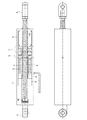
図1の全体図に示すように、本発明の電動アクチュエータでは、円筒状のハウジング1の内部に正転・逆転可能な電気モータ2が設置される。電気モータ2は、詳細な図示は省略するが、一般的なDCモータ又はACモータと同じく、ハウジング1に固定されたステータの内側に回転するロータ(電機子)が配置されたもので、ロータの内側には、中空のスリーブ状回転子3が固着されている。そして、円筒状のハウジング1の中心には、中空のスリーブ状回転子3を貫通して延びるねじ軸4が配置され、ねじ軸4に形成されたねじには、ハウジング1の軸方向の一端に置かれたナット部材5が嵌め合わされる。
Hereinafter, the electric actuator of the present invention will be described with reference to the drawings.
As shown in the overall view of FIG. 1, in the electric actuator of the present invention, an electric motor 2 capable of normal rotation and reverse rotation is installed inside a cylindrical housing 1. Although the electric motor 2 is not shown in detail, a rotor (armature) that rotates inside a stator fixed to the housing 1 is arranged like a general DC motor or AC motor. On the inside, a hollow sleeve-
ナット部材5は、ブレーキ機構6及び減速機構7を介してスリーブ状回転子3に連結され、電気モータ2により回転されて、ねじ軸4を直線運動させる。ナット部材5とねじとの間にはボール51が介在されてボールねじ機構を構成しており、回転運動を直線運動へ変換する際の摩擦損失を低減する。
ねじ軸4は、電動アクチュエータの出力部材となるものであり、駆動対象物がウイングボディのウイングである場合には、ねじ軸4の先端のクレビス(接続金具)41がウイングに連結されるとともに、ハウジング1に固定された反対側のクレビス11がウイングボディの後部フレーム等の上部に枢着される。ねじ軸4のクレビス41とハウジング1との間には、塵埃等の侵入を防止するため、伸縮する蛇腹状のゴム管を設けてもよい。また、ねじ軸4のクレビス41の反対の端部には、抜け止め用ガイド42が固定されている。
The
The screw shaft 4 is an output member of the electric actuator. When the driven object is a wing of the wing body, a clevis (connection fitting) 41 at the tip of the screw shaft 4 is coupled to the wing, The
本発明の電動アクチュエータにおいて、電気モータ2のスリーブ状回転子3に接続されるブレーキ機構6は、この実施例では、無励磁作動形の乾式単板ブレーキとなっている。このブレーキ機構6は、図2に示すように、スリーブ状回転子3に固定されたブレーキ用ディスク61と、ブレーキ用ディスク61を収容するブレーキ作動体62を備える。ブレーキ作動体62は、磁性体で製作され、ブレーキ用ディスク61を挟んで配置された2枚の円板の外周を連結した部材であり、一方の円板のブレーキ用ディスク61と対向する面には摩擦ライニング63が施されて、その円板が摩擦板を構成している。
さらに、ブレーキ機構6は、ハウジング1に固定される固定部材を有し、この固定部材には、ブレーキ作動体62の摩擦ライニング63をブレーキ用ディスク61に押し付ける押圧ばね64と、ブレーキ作動体62を磁気力で吸引し摩擦ライニング63を離間させる励磁コイル65とが取り付けられる。
In the electric actuator of the present invention, the
Further, the
そして、ブレーキ機構6には、ブレーキを手動で解除可能するための手動解除装置が設けられる。手動解除装置は、ブレーキ作動体62を押圧ばね64と反対方向に押すための押圧ボール66と、これを移動するため、ハウジング1のねじ穴に嵌め込まれた解除ねじ67からなる。解除ねじ67の先端には円錐体が形成してあり、円錐体の側面が押圧ボール66に接触している。
The
ここで、本発明の電動アクチュエータのブレーキ機構6の作動について説明する。
ブレーキ機構6のブレーキ作動体62は、通常は押圧ばね64に押されていて、その摩擦ライニング63がブレーキ用ディスク61に圧着され、電気モータ2のスリーブ状回転子3には制動力が作用している。このブレーキ機構6では、ウイング等の駆動対象物を変位させるよう電気モータ2に通電したときは、それに連動して励磁コイル65にも電流が流れて励磁されるように制御回路が構成されている。したがって、電気モータ2に通電されると、ブレーキ作動体62が吸引されて摩擦ライニング63とブレーキ用ディスク61とが離間し、ねじ軸4の移動に対する制動力が解除される。これに対し、電気モータ2の通電が遮断されると、電気モータ2のスリーブ状回転子3には直ちに制動力が作用してねじ軸4が停止するため、スリーブ状回転子3の慣性モーメントが大きくとも、電気モータ2の通電とその遮断により駆動対象物の位置を正確に制御することができる。
Here, the operation of the
The
万一、電気モータ2や励磁コイル65の通電系統などに故障が生じ、スリーブ状回転子3に制動力が作用したままとなったときには、手動解除装置の解除ねじ67をドライバーでハウジング1の中心に向けてねじ込む。これにより、押圧ボール66が解除ねじ67の先端の円錐体に押されて孔の中を図2の右方に移動し、ブレーキ作動体62を押圧ばね64に抗して移動させ、摩擦ライニング63とブレーキ用ディスク61とを強制的に離間させる。スリーブ状回転子3に作用する制動力が消失するため、ねじ軸4の拘束が解除されて、駆動対象物を修理に適した位置に手動で動かすことができるようになる。
手動解除装置としては、図2下部の変形例に示すように、押圧ボールに代えて斜面を形成したピン66Aを孔内に挿入し、ピン66Aの斜面と接触するカム体を取り付けた解除ねじ67Aを押し込むようにしてもよい。
Should a failure occur in the energization system of the electric motor 2 or the
As a manual release device, as shown in the modified example in the lower part of FIG. 2, a
本発明のブレーキ機構6は、減速機構7により回転速度の減少する前の位置、つまり、回転トルクが増大する前の位置に置かれているので、ブレーキ用ディスク61の制動に要する摩擦力は小さい。また、スリーブ状回転子3の外周部の径が大きい部分に作用させるので、この点からも制動に要する摩擦力は小さいものとなる。図2の実施例では、スリーブ状回転子3を延長しその延長部にブレーキ用ディスク61を形成しているが、図の2点鎖線に示すように、スリーブ状回転子に固定した別体の中空軸にブレーキ用ディスクを形成することもできる。
Since the
図3に示すように、この実施例では、本発明の電動アクチュエータの減速機構7として遊星歯車式減速装置が採用されている。
図3の遊星歯車式減速装置においては、太陽歯車SGを形成した中空の太陽歯車軸71がスリーブ状回転子3にフランジ結合される。ハウジング1には、内歯歯車であるリング歯車RGが固定され、太陽歯車SGとリング歯車RGとの間には、両方の歯車と噛み合う遊星歯車PGが配置される。そして、遊星歯車PGを支持する支持軸52がナット部材5に固着されている。
As shown in FIG. 3, in this embodiment, a planetary gear speed reduction device is employed as the
In the planetary gear speed reduction device of FIG. 3, a hollow sun gear shaft 71 that forms a sun gear SG is flange-coupled to the sleeve-
遊星歯車PGを支持するナット部材5は、一般の遊星歯車装置におけるプラネット・キャリアに相当するものであって、遊星歯車PGの公転と同一速度で回転する。つまり、この減速機構7は、太陽歯車軸71を入力軸とし、これと回転中心軸が同軸であるナット部材5(支持軸52)を出力軸とする減速装置であり、その減速比は、よく知られているように、次の式で表される。
減速比:1/(1+(ZRG/ZSG))
ZSG;太陽歯車の歯数、ZRG;リング歯車の歯数
このように、この実施例の電動アクチュエータでは、電気モータ2の回転速度が上記の減速比に従って減速され、ナット部材5を回転させる。スリーブ状回転子3、減速機構7及びナット部材5は、全て同心状にハウジング1の内部に収容され、その中心に配置されたねじ軸4を往復動させるので、本発明では、電動アクチュエータを直線状のコンパクトな形態として、車両への搭載性を向上させることができる。
The
Reduction ratio: 1 / (1+ (ZRG / ZSG))
ZSG: Number of teeth of sun gear, ZRG: Number of teeth of ring gear Thus, in the electric actuator of this embodiment, the rotational speed of the electric motor 2 is reduced according to the reduction ratio described above, and the
再び図1を参照して、本発明の電動アクチュエータにおける制御装置の概要について説明する。
電動アクチュエータのハウジング1の内部には、電気モータ2を挟んでブレーキ機構6等とは反対側に、スリーブ状回転子3の回転位置を検出するロータリーエンコーダ8が設置されるとともに、電動モータ2を制御するモータ制御装置9も設置されている。回転位置検出器であるロータリーエンコーダ8を設け、電動モータ2の通電電流のチョッパ制御や周波数のインバータ制御を実施すると、一般的なDCモータ又はACモータを用いたとしても、駆動対象物の位置や速度を容易に制御することができる。駆動対象物がウイングである場合には、スロースタート、スローストップの制御を容易に実行して、開放開始時の雨水の巻き込み防止、閉鎖時の衝撃防止を図ることができる。
With reference to FIG. 1 again, the outline of the control device in the electric actuator of the present invention will be described.
Inside the housing 1 of the electric actuator, a rotary encoder 8 for detecting the rotational position of the sleeve-
また、電動アクチュエータの駆動対象物がウイングであれば、制御装置9には、複数のアクチュエータを同期して駆動する同期制御部が設けられる。同期制御部は、例えば、2個の電動アクチュエータにおける電気モータの回転量を比較し、回転量が少ない方のアクチュエータの通電量を増加させる補正を実行するよう構成されたもので、これにより、ウイングボディの前後のフレーム上部に設置される電動アクチュエータを同期して、ウイングの開閉中の捩りなどの作動不良を防止できる。
なお、電気モータとしてパルスモータを用い、発生したパルス数に応じた回転角度となる構成としたときは、ロータリーエンコーダ等の回転数検出器は不要となる。サーボモータを用いたときは、1個の電気モータの回転位置を、他のアクチュエータにおける電気モータの回転位置に追随させることが可能となる。
If the object to be driven by the electric actuator is a wing, the control device 9 is provided with a synchronization control unit that drives a plurality of actuators in synchronization. For example, the synchronization control unit is configured to compare the rotation amounts of the electric motors in the two electric actuators, and to perform correction to increase the energization amount of the actuator having the smaller rotation amount. By synchronizing the electric actuators installed on the upper and lower frames of the body, it is possible to prevent malfunctions such as torsion during opening and closing of the wing.
When a pulse motor is used as the electric motor and the rotation angle is in accordance with the number of generated pulses, a rotation number detector such as a rotary encoder is not necessary. When a servo motor is used, the rotational position of one electric motor can be made to follow the rotational position of the electric motor in another actuator.
以上詳述したように、本発明の車両用の電動アクチュエータは、電気モータにねじ軸が貫通する中空の回転子を設けるとともに、手動解除装置付きのブレーキ機構及びナット部材回転用の減速機構を同軸状に配置したものである。上述の実施例では、電動アクチュエータをウイングの駆動装置として用いた場合について説明しているが、本発明の車両用の電動アクチュエータは、テールゲートの昇降用装置等の可動部分に適用できるのは言うまでもない。また、実施例のブレーキ機構である乾式単板ブレーキに代えて、スリーブ状回転子の円周面にブレーキシューを押し付ける形式のブレーキを採用する、減速機構である遊星歯車装置に代えて、両面に歯数の異なる歯形が形成された弾性リングを設置する、いわゆるハーモニック型(ハーモニックは登録商標)の減速装置を採用するなど、上述の実施例に対し種々の変形が可能であることは明らかである。 As described in detail above, the electric actuator for a vehicle according to the present invention is provided with a hollow rotor through which a screw shaft penetrates an electric motor, and a brake mechanism with a manual release device and a speed reduction mechanism for rotating a nut member are coaxial. It is arranged in a shape. In the above-described embodiments, the case where the electric actuator is used as a wing drive device has been described, but it goes without saying that the vehicle electric actuator of the present invention can be applied to a movable part such as a tailgate lifting device. Yes. Also, instead of the dry single plate brake that is the brake mechanism of the embodiment, instead of the planetary gear device that is a reduction mechanism that employs a brake of a type in which a brake shoe is pressed against the circumferential surface of the sleeve-like rotor, on both sides It is clear that various modifications can be made to the above-described embodiment, such as using a so-called harmonic type (harmonic is a registered trademark) speed reducer by installing an elastic ring in which tooth forms with different numbers of teeth are formed. .
1 ハウジング
2 電気モータ
3 スリーブ状回転子
4 ねじ軸
5 ナット部材
6 ブレーキ機構
61 ブレーキ用ディスク
63 摩擦ライニング
65 励磁コイル
67 解除ねじ(手動解除用)
7 減速機構
8 ロータリーエンコーダ
DESCRIPTION OF SYMBOLS 1 Housing 2
7 Deceleration mechanism 8 Rotary encoder
Claims (5)
前記電動アクチュエータは、車両に装備され、
前記電気モータは、前記ねじ軸が貫通する中空のスリーブ状回転子を備えるとともに、前記スリーブ状回転子が、入出力軸の回転中心軸が同軸である減速機構を介して前記ナット部材に接続されており、
前記スリーブ状回転子と前記減速機構との間には、前記電気モータへの通電が遮断されたときに自動的に制動力を作用させるブレーキ機構が設置され、前記ブレーキ機構は、手動で解除可能であることを特徴とする電動アクチュエータ。 An electric actuator in which a screw shaft formed with a screw and a nut member fitted to the screw are installed, and the screw shaft is reciprocated by rotating the nut member by an electric motor capable of normal / reverse rotation fixed to a housing Because
The electric actuator is installed in a vehicle,
The electric motor includes a hollow sleeve-like rotor through which the screw shaft passes, and the sleeve-like rotor is connected to the nut member via a speed reduction mechanism in which the rotation center axis of the input / output shaft is coaxial. And
A brake mechanism is provided between the sleeve-like rotor and the speed reduction mechanism to automatically apply a braking force when the electric motor is de-energized. The brake mechanism can be released manually. The electric actuator characterized by being.
Priority Applications (1)
| Application Number | Priority Date | Filing Date | Title |
|---|---|---|---|
| JP2013066612A JP5877811B2 (en) | 2013-03-27 | 2013-03-27 | Electric actuator for vehicles |
Applications Claiming Priority (1)
| Application Number | Priority Date | Filing Date | Title |
|---|---|---|---|
| JP2013066612A JP5877811B2 (en) | 2013-03-27 | 2013-03-27 | Electric actuator for vehicles |
Publications (2)
| Publication Number | Publication Date |
|---|---|
| JP2014190436A true JP2014190436A (en) | 2014-10-06 |
| JP5877811B2 JP5877811B2 (en) | 2016-03-08 |
Family
ID=51836896
Family Applications (1)
| Application Number | Title | Priority Date | Filing Date |
|---|---|---|---|
| JP2013066612A Active JP5877811B2 (en) | 2013-03-27 | 2013-03-27 | Electric actuator for vehicles |
Country Status (1)
| Country | Link |
|---|---|
| JP (1) | JP5877811B2 (en) |
Cited By (9)
| Publication number | Priority date | Publication date | Assignee | Title |
|---|---|---|---|---|
| JP2016153263A (en) * | 2015-02-20 | 2016-08-25 | 日本フルハーフ株式会社 | Electric actuator |
| JP2017219135A (en) * | 2016-06-08 | 2017-12-14 | 株式会社ツバキE&M | Linear actuator and lid opening/closing mechanism using the same |
| WO2018042048A1 (en) | 2016-09-05 | 2018-03-08 | Reac Ab | Hoist device comprising a linear actuator with a manual lowering device |
| JP2018069884A (en) * | 2016-10-27 | 2018-05-10 | 株式会社ミツバ | Actuator and actuator for opening and closing vehicle door |
| CN108518466A (en) * | 2018-04-19 | 2018-09-11 | 宁波海仕凯驱动科技有限公司 | A kind of compact-sized linear actuators |
| KR101927488B1 (en) | 2017-09-07 | 2018-12-11 | 주식회사 한화 | Linear actuator having free fall operation |
| WO2019078121A1 (en) * | 2017-10-19 | 2019-04-25 | 日本精工株式会社 | Extendible-contractible link and suspension |
| US10829155B2 (en) | 2017-10-19 | 2020-11-10 | Nsk Ltd. | Suspension operation system and suspension operation terminal |
| US10940730B2 (en) | 2017-10-19 | 2021-03-09 | Nsk Ltd. | Extension-retraction link and suspension |
Families Citing this family (1)
| Publication number | Priority date | Publication date | Assignee | Title |
|---|---|---|---|---|
| WO2020205164A1 (en) | 2019-04-05 | 2020-10-08 | Oshkosh Corporation | Scissor lift descent control systems and methods |
Citations (5)
| Publication number | Priority date | Publication date | Assignee | Title |
|---|---|---|---|---|
| JPH0539817A (en) * | 1991-08-05 | 1993-02-19 | Fuji Electric Co Ltd | Manual release device for unexcited operation disc brake device |
| JP2007089374A (en) * | 2005-09-26 | 2007-04-05 | Tsubaki Emerson Co | Electric cylinder |
| JP2007120621A (en) * | 2005-10-28 | 2007-05-17 | Ogino Kogyo Kk | Positioning device |
| JP2008238877A (en) * | 2007-03-26 | 2008-10-09 | Nippon Fruehauf Co Ltd | Wing opening/closing control device and opening/closing controlling method of wing body |
| JP2011174601A (en) * | 2010-01-28 | 2011-09-08 | Nsk Ltd | Ball screw device with splines and friction stir welding apparatus using the same |
-
2013
- 2013-03-27 JP JP2013066612A patent/JP5877811B2/en active Active
Patent Citations (5)
| Publication number | Priority date | Publication date | Assignee | Title |
|---|---|---|---|---|
| JPH0539817A (en) * | 1991-08-05 | 1993-02-19 | Fuji Electric Co Ltd | Manual release device for unexcited operation disc brake device |
| JP2007089374A (en) * | 2005-09-26 | 2007-04-05 | Tsubaki Emerson Co | Electric cylinder |
| JP2007120621A (en) * | 2005-10-28 | 2007-05-17 | Ogino Kogyo Kk | Positioning device |
| JP2008238877A (en) * | 2007-03-26 | 2008-10-09 | Nippon Fruehauf Co Ltd | Wing opening/closing control device and opening/closing controlling method of wing body |
| JP2011174601A (en) * | 2010-01-28 | 2011-09-08 | Nsk Ltd | Ball screw device with splines and friction stir welding apparatus using the same |
Cited By (13)
| Publication number | Priority date | Publication date | Assignee | Title |
|---|---|---|---|---|
| JP2016153263A (en) * | 2015-02-20 | 2016-08-25 | 日本フルハーフ株式会社 | Electric actuator |
| JP2017219135A (en) * | 2016-06-08 | 2017-12-14 | 株式会社ツバキE&M | Linear actuator and lid opening/closing mechanism using the same |
| WO2018042048A1 (en) | 2016-09-05 | 2018-03-08 | Reac Ab | Hoist device comprising a linear actuator with a manual lowering device |
| SE541297C2 (en) * | 2016-09-05 | 2019-06-18 | Reac Ab | Hoist device comprising a linear actuator with a manual lowering device |
| JP2018069884A (en) * | 2016-10-27 | 2018-05-10 | 株式会社ミツバ | Actuator and actuator for opening and closing vehicle door |
| WO2019050066A1 (en) * | 2017-09-07 | 2019-03-14 | 주식회사 한화 | Linear actuator having free fall function |
| KR101927488B1 (en) | 2017-09-07 | 2018-12-11 | 주식회사 한화 | Linear actuator having free fall operation |
| WO2019078121A1 (en) * | 2017-10-19 | 2019-04-25 | 日本精工株式会社 | Extendible-contractible link and suspension |
| JP6575722B1 (en) * | 2017-10-19 | 2019-09-18 | 日本精工株式会社 | Telescopic link and suspension |
| US10829155B2 (en) | 2017-10-19 | 2020-11-10 | Nsk Ltd. | Suspension operation system and suspension operation terminal |
| US10940730B2 (en) | 2017-10-19 | 2021-03-09 | Nsk Ltd. | Extension-retraction link and suspension |
| CN108518466A (en) * | 2018-04-19 | 2018-09-11 | 宁波海仕凯驱动科技有限公司 | A kind of compact-sized linear actuators |
| CN108518466B (en) * | 2018-04-19 | 2023-09-26 | 宁波海仕凯驱动科技有限公司 | Linear actuator with compact structure |
Also Published As
| Publication number | Publication date |
|---|---|
| JP5877811B2 (en) | 2016-03-08 |
Similar Documents
| Publication | Publication Date | Title |
|---|---|---|
| JP5877811B2 (en) | Electric actuator for vehicles | |
| CN102241250B (en) | Electric parking brake | |
| US20130140112A1 (en) | Brake device comprising a rotor of an eddy current disk brake, the rotor forming the brake disk of a friction disk brake | |
| US7806239B2 (en) | Electromechanical actuating device for a wheel brake system of a motor vehicle and a brake system equipped with such an actuating device | |
| CN211308536U (en) | Driving-parking integrated brake for vehicle and vehicle with same | |
| EP3271602B1 (en) | Brake actuator | |
| KR20120009407A (en) | Method of operating a drive train of a motor vehicle and corresponding drive train | |
| US20110240410A1 (en) | Elevator brake actuator having a shape-changing material for brake control | |
| CN106218665A (en) | A kind of active-passive integrated formula rail vehicle motor drives friction stopping device | |
| JP2008535732A5 (en) | ||
| CN105164445A (en) | Electromagnetic active brake | |
| JP2020534482A (en) | Railroad vehicle motor-driven mechanical friction braking device | |
| KR101699070B1 (en) | Device of electro mechanical brake | |
| CN110465931B (en) | Driving device and robot | |
| US20100283215A1 (en) | Clamping device for machine tools | |
| ITRM980601A1 (en) | MOTOR VEHICLE BRAKE ACTUATOR | |
| US11473636B2 (en) | Disc brake having an electromechanical actuator, in particular an electromechanical parking brake actuator | |
| US20220003288A1 (en) | Method for determining design parameters of an electromechanical brake, and electromechanical brake | |
| JP6784203B2 (en) | Drive device | |
| JP4802117B2 (en) | Load body driving device for opening and closing flow path | |
| CN212447476U (en) | Electro-hydraulic brake caliper and vehicle brake system | |
| KR100418291B1 (en) | Door presser apparatus for vehicle | |
| KR101610533B1 (en) | Roof spoiler device for vehicle | |
| US20100072007A1 (en) | Machine tool, production machine and/or handling machine | |
| JP2022015810A (en) | Electric actuator |
Legal Events
| Date | Code | Title | Description |
|---|---|---|---|
| A621 | Written request for application examination |
Free format text: JAPANESE INTERMEDIATE CODE: A621 Effective date: 20140901 |
|
| A977 | Report on retrieval |
Free format text: JAPANESE INTERMEDIATE CODE: A971007 Effective date: 20150626 |
|
| A131 | Notification of reasons for refusal |
Free format text: JAPANESE INTERMEDIATE CODE: A131 Effective date: 20150707 |
|
| A521 | Written amendment |
Free format text: JAPANESE INTERMEDIATE CODE: A523 Effective date: 20150904 |
|
| TRDD | Decision of grant or rejection written | ||
| A01 | Written decision to grant a patent or to grant a registration (utility model) |
Free format text: JAPANESE INTERMEDIATE CODE: A01 Effective date: 20160126 |
|
| A61 | First payment of annual fees (during grant procedure) |
Free format text: JAPANESE INTERMEDIATE CODE: A61 Effective date: 20160126 |
|
| R150 | Certificate of patent or registration of utility model |
Ref document number: 5877811 Country of ref document: JP Free format text: JAPANESE INTERMEDIATE CODE: R150 |