JP2014188612A - Impact tool - Google Patents
Impact tool Download PDFInfo
- Publication number
- JP2014188612A JP2014188612A JP2013065154A JP2013065154A JP2014188612A JP 2014188612 A JP2014188612 A JP 2014188612A JP 2013065154 A JP2013065154 A JP 2013065154A JP 2013065154 A JP2013065154 A JP 2013065154A JP 2014188612 A JP2014188612 A JP 2014188612A
- Authority
- JP
- Japan
- Prior art keywords
- hammer
- tool
- impact
- holding member
- peripheral surface
- Prior art date
- Legal status (The legal status is an assumption and is not a legal conclusion. Google has not performed a legal analysis and makes no representation as to the accuracy of the status listed.)
- Pending
Links
- 230000002093 peripheral effect Effects 0.000 claims description 45
- 230000003116 impacting effect Effects 0.000 abstract 1
- 229910000831 Steel Inorganic materials 0.000 description 16
- 239000010959 steel Substances 0.000 description 16
- 239000003638 chemical reducing agent Substances 0.000 description 12
- 230000006835 compression Effects 0.000 description 10
- 238000007906 compression Methods 0.000 description 10
- 238000005192 partition Methods 0.000 description 9
- 210000000078 claw Anatomy 0.000 description 4
- 239000002023 wood Substances 0.000 description 4
- 241001272720 Medialuna californiensis Species 0.000 description 2
- 230000000694 effects Effects 0.000 description 2
- 230000000116 mitigating effect Effects 0.000 description 2
- 230000002159 abnormal effect Effects 0.000 description 1
- 238000013459 approach Methods 0.000 description 1
- 230000005540 biological transmission Effects 0.000 description 1
- 230000003247 decreasing effect Effects 0.000 description 1
- 238000012986 modification Methods 0.000 description 1
- 230000004048 modification Effects 0.000 description 1
- 238000007789 sealing Methods 0.000 description 1
Images


Abstract
Description
本発明は、ハンマで工具保持部材を打撃する打撃工具に関する。 The present invention relates to a striking tool that strikes a tool holding member with a hammer.
従来、動力源の動力をハンマに伝達してハンマを往復動作させ、ハンマで工具保持部材を打撃する打撃工具が知られており、その一例が特許文献1に記載されている。この特許文献1に記載された打撃工具は、ボルトの締め付けを行うことができる。打撃工具は、工具本体の内部に動力源の回転軸が設けられており、工具本体の内部に隔壁が設けられている。また、工具本体の内部に回転軸と同軸にスピンドルが設けられており、回転軸の回転力をスピンドルに伝達する減速機が設けられている。 2. Description of the Related Art Conventionally, hitting tools that transmit the power of a power source to a hammer to reciprocate the hammer and hit a tool holding member with the hammer are known. The impact tool described in Patent Document 1 can tighten bolts. In the impact tool, a rotating shaft of a power source is provided inside the tool body, and a partition is provided inside the tool body. Further, a spindle is provided in the tool main body coaxially with the rotary shaft, and a speed reducer for transmitting the rotational force of the rotary shaft to the spindle is provided.
減速機は、回転軸と一体回転するサンギヤと、工具本体の内部に固定され、かつ、サンギヤを取り囲むように設けたリングギヤと、サンギヤ及びリングギヤに噛み合うピニオンギヤを自転及び公転可能に支持したキャリヤとを有する。キャリヤは、回転軸の中心線に沿った方向に2分割された第1構成片及び第2構成片を備えている。隔壁には軸孔が設けられており、軸孔の内周面と第1構成片の外周面との間に軸受が設けられている。第2構成片はスピンドルと一体に形成されている。 The speed reducer includes a sun gear that rotates integrally with the rotating shaft, a ring gear that is fixed inside the tool body and that surrounds the sun gear, and a carrier that supports the sun gear and the pinion gear that meshes with the ring gear so as to rotate and revolve. Have. The carrier includes a first component piece and a second component piece that are divided into two in the direction along the center line of the rotation shaft. A shaft hole is provided in the partition wall, and a bearing is provided between the inner peripheral surface of the shaft hole and the outer peripheral surface of the first component piece. The second component piece is formed integrally with the spindle.
さらに、工具本体に回転可能に取り付けられた工具保持部材が設けられており、工具保持部材はスピンドルと同心状に配置されている。工具保持部材は工具保持孔を有し、工具保持孔に先端工具が着脱される。工具保持部材におけるスピンドル側の端部に、半径方向で外側に向けて突出された羽根が設けられている。羽根は円周方向で2箇所に設けられている。また、スピンドルの外周面にV字形状の第1カム溝が形成されている。 Furthermore, a tool holding member rotatably attached to the tool body is provided, and the tool holding member is arranged concentrically with the spindle. The tool holding member has a tool holding hole, and the tip tool is attached to and detached from the tool holding hole. A blade projecting outward in the radial direction is provided at an end of the tool holding member on the spindle side. The blades are provided at two locations in the circumferential direction. A V-shaped first cam groove is formed on the outer peripheral surface of the spindle.
一方、スピンドルの外周側にハンマが設けられている。ハンマは環状であり、かつ、スピンドルと同心状に配置されている。ハンマの外周面に三角形状の第2カム溝が形成されている。カム溝とカム溝とにより、ボールが保持されている。ハンマはスピンドルに対して中心線に沿った方向に移動可能であり、ハンマと第2構成片との間の空間に、圧縮ばねが設けられている。さらに、ハンマには羽根に係合または解放される爪が設けられている。さらに、中心線に沿った方向で、ハンマと第2構成片との間にストッパが設けられている。ストッパは弾性体により構成されており、ストッパは第2構成片に接触して設けられている。 On the other hand, a hammer is provided on the outer peripheral side of the spindle. The hammer is annular and is arranged concentrically with the spindle. A triangular second cam groove is formed on the outer peripheral surface of the hammer. The ball is held by the cam groove and the cam groove. The hammer is movable in a direction along the center line with respect to the spindle, and a compression spring is provided in a space between the hammer and the second component piece. Further, the hammer is provided with a claw that is engaged with or released from the blade. Further, a stopper is provided between the hammer and the second component piece in a direction along the center line. The stopper is made of an elastic body, and the stopper is provided in contact with the second component piece.
特許文献1に記載された打撃工具は、回転軸の回転力が減速機を経由してスピンドルに伝達され、スピンドルの回転力が、ボール、ハンマを経由して工具保持部材に伝達される。そして、工具保持部材に保持された先端工具がボルトの締め付けを行う。ボルトの締め付けに必要なトルクが増加すると工具保持部材が停止するがハンマの回転が継続される。このため、ハンマは圧縮ばねの力に抗して工具保持部材から離れる向きで移動する。 In the impact tool described in Patent Document 1, the rotational force of the rotary shaft is transmitted to the spindle via the speed reducer, and the rotational force of the spindle is transmitted to the tool holding member via the ball and the hammer. Then, the end tool held by the tool holding member tightens the bolt. When the torque required for tightening the bolt increases, the tool holding member stops, but the hammer continues to rotate. For this reason, the hammer moves in a direction away from the tool holding member against the force of the compression spring.
ハンマが工具保持部材から離れる向きで移動すると、羽根と爪との係合が解除され、爪が羽根を乗り越える。すると、圧縮ばねの力でハンマが工具保持部材に近づく向きで移動し、ハンマが回転しながら爪と羽根とが噛み合うことで、回転方向の打撃力が工具保持部材を介して先端工具に伝達される。上記のように、ハンマが工具保持部材から離れる向きで移動すると、ボールが第1カム溝の端部に到達する前にハンマがストッパに衝突する。ここで、ストッパが弾性変形することで、ハンマの運動エネルギを吸収する。したがって、ボールが第1カム溝の端部に衝突する衝撃力を緩和できる。 When the hammer moves away from the tool holding member, the engagement between the blade and the claw is released, and the claw gets over the blade. Then, the hammer moves in the direction approaching the tool holding member by the force of the compression spring, and the hammering force engages with the claw and the blade while rotating the hammer, so that the impact force in the rotating direction is transmitted to the tip tool through the tool holding member. The As described above, when the hammer moves away from the tool holding member, the hammer collides with the stopper before the ball reaches the end of the first cam groove. Here, the stopper is elastically deformed to absorb the kinetic energy of the hammer. Therefore, the impact force with which the ball collides with the end portion of the first cam groove can be reduced.
しかしながら、上述の特許文献1に記載された打撃工具においては、ハンマがストッパに衝突すると、その衝撃力が、キャリヤ、軸受を介して工具本体に伝達される可能性があった。 However, in the impact tool described in the above-mentioned Patent Document 1, when the hammer collides with the stopper, the impact force may be transmitted to the tool body via the carrier and the bearing.
本発明の目的は、ハンマが工具保持部材から離れる向きで移動する際に、ストッパに加わる衝撃力を低減することの可能な打撃工具を提供することにある。 The objective of this invention is providing the impact tool which can reduce the impact force added to a stopper, when a hammer moves in the direction away from a tool holding member.
一実施形態の打撃工具は、先端工具を保持する工具保持部材を、往復動作するハンマで打撃する打撃工具であって、前記ハンマが往復動作可能に収容された工具本体と、前記工具本体の内部に設けられ、前記ハンマが前記工具保持部材から離れる向きに後退することを緩和する緩和機構と、を有する。 The striking tool of one embodiment is a striking tool that strikes a tool holding member that holds a tip tool with a reciprocating hammer, and a tool main body in which the hammer is reciprocally movable; And a mitigation mechanism for mitigating retraction of the hammer in a direction away from the tool holding member.
他の実施形態の打撃工具は、先端工具を保持する工具保持部材を、往復動作するハンマで打撃する打撃工具であって、前記ハンマが往復動作可能に収容された工具本体と、前記工具本体の内部に設けられて前記ハンマにおける往復動作方向の端部に接触し、前記ハンマが前記工具保持部材から離れる向きで動作する範囲を規制するストッパと、前記工具本体の内部に設けられ、かつ、前記ハンマが前記ストッパに接触する前に、前記ハンマが前記工具保持部材から離れる向きで動作する速度を、摩擦または粘性により低減する緩和機構と、を有する。 The striking tool of another embodiment is a striking tool for striking a tool holding member that holds a tip tool with a reciprocating hammer, and a tool main body in which the hammer is reciprocally movable, A stopper that is provided inside and contacts an end of the hammer in a reciprocating direction, and that regulates a range in which the hammer moves in a direction away from the tool holding member; and provided inside the tool body; and A relaxation mechanism that reduces, by friction or viscosity, a speed at which the hammer moves in a direction away from the tool holding member before the hammer contacts the stopper.
他の実施形態は、前記ハンマは往復動作する中心線を囲む略円筒形状であり、前記ハンマが動作する速度を摩擦により低減する前記緩和機構は、前記工具本体の内面に設けられ、かつ、前記ハンマの外周面に接触する接触部材を含む。 In another embodiment, the hammer has a substantially cylindrical shape surrounding a reciprocating center line, and the relaxation mechanism for reducing the speed at which the hammer operates by friction is provided on the inner surface of the tool body, and The contact member which contacts the outer peripheral surface of a hammer is included.
他の実施形態の打撃工具は、先端工具を保持する工具保持部材を、往復動作するハンマで打撃する打撃工具であって、前記ハンマが往復動作可能に収容された工具本体と、前記工具本体の内部であって前記ハンマの半径方向で外側に設けられ、前記ハンマが前記工具保持部材から離れる方向に後退する際に前記ハンマに接触して前記ハンマが動作する速度を緩和する接触部材と、を有する。 The striking tool of another embodiment is a striking tool for striking a tool holding member that holds a tip tool with a reciprocating hammer, and a tool main body in which the hammer is reciprocally movable, A contact member that is provided inside and radially outward of the hammer and that reduces the speed at which the hammer operates by contacting the hammer when the hammer is retracted away from the tool holding member; Have.
他の実施形態の打撃工具は、先端工具を保持する工具保持部材を、往復動作する略円筒形状のハンマで打撃する打撃工具であって、前記ハンマが往復動作可能に収容された工具本体と、前記工具本体の内部に設けられ、前記ハンマが前記工具保持部材から離れる向きに後退することを緩和する接触部材と、を有し、前記接触部材は、前記ハンマが最も後退した状態において、往復方向における前記ハンマの長さ領域内に位置する。 The striking tool of another embodiment is a striking tool that strikes a tool holding member that holds a tip tool with a substantially cylindrical hammer that reciprocates, and a tool main body in which the hammer is accommodated so as to be reciprocally movable; A contact member that is provided inside the tool body and relieves the hammer from retreating away from the tool holding member, and the contact member is in a reciprocating direction when the hammer is most retracted. In the length region of the hammer.
一実施形態の打撃工具によれば、ハンマが工具保持部材から離れる向きで後退することが、緩和機構により緩和される。したがって、ハンマからストッパに加えられる衝撃力を低減できる。 According to the striking tool of one embodiment, the retraction of the hammer in the direction away from the tool holding member is relieved by the relieving mechanism. Therefore, the impact force applied from the hammer to the stopper can be reduced.
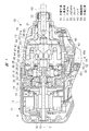
以下、本発明の一実施の形態について、図面を用いて詳細に説明する。図1に示す打撃工具10は、ボルトの締め付けまたは緩めに用いるインパクトドライバである。打撃工具10は、中空の工具本体11を有しており、工具本体11は、ハウジング12にハンマケース13を固定して形成されている。ハウジング12の内部Aに電動モータ14が設けられており、電動モータ14の回転軸15は2個の軸受16,17により回転可能に支持されている。電動モータ14は回転軸15の回転方向を切り替えることができる。
Hereinafter, an embodiment of the present invention will be described in detail with reference to the drawings. The
ハウジング12の内部Aとハンマケース13の内部Bとを仕切る隔壁18が設けられている。隔壁18は環状に形成されており、隔壁18の内周面と回転軸15との間に軸受17が配置され、ハウジング12と回転軸15との間に軸受16が配置されている。回転軸15は中心線Cを中心として回転する。
A
ハンマケース13は軸孔19を有しており、軸孔19にスリーブ20が取り付けられている。スリーブ20の内部に、工具保持部材としてのアンビル21が回転可能に配置されている。アンビル21は中心線Cを中心として回転可能である。また、アンビル21は、ハンマケース13の内部Bから、工具本体11の外部に亘って設けられており、アンビル21に中心線Cを中心とする工具保持孔22が設けられている。工具保持孔22は、工具本体11の外部に開口されている。工具保持孔22に先端工具53が着脱される。
The
また、アンビル21に、工具保持孔22と同心状に支持孔21aが設けられている。支持孔21aは内部Bに向けて開口されている。支持孔21aは工具保持孔22につながっていない。さらに、アンビル21の外周面において、ハンマケース13の内部Bに配置された箇所には、突部23が2個設けられている。2個の突部23は、アンビル21の円周方向に180度間隔で配置されている。
The
一方、ハンマケース13の内部Bには、減速機24が設けられている。減速機24は、中心線Cに沿った方向で、軸受17とアンビル21との間に配置されている。減速機24は、電動モータ14の回転力、すなわちトルクをアンビル21に伝達する動力伝達装置であり、減速機24はシングルピニオン型の遊星歯車機構により構成されている。
On the other hand, a
減速機24は、回転軸15と同心状に配置されたサンギヤ25と、サンギヤ25の外周側を取り囲むように設けたリングギヤ26と、サンギヤ25及びリングギヤ26に噛み合わされた複数のピニオンギヤ27を自転、かつ、公転可能に支持したキャリヤ28とを有する。サンギヤ25は中間軸29の外周面に形成されており、中間軸29は回転軸15と一体回転する。リングギヤ26は隔壁18に固定されている。さらに、リングギヤ26の外周面とハンマケース13の内周面との間に密封装置、具体的にはOリング30が介在されている。
The
キャリヤ28は、ピニオンギヤ27が取り付けられたピニオンピン31と、ピニオンピン31の長手方向の両端に接続された第1構成片32及び第2構成片33とを有している。第1構成片32は環状であり、第1構成片32の内部に中間軸29の一部が配置されている。隔壁18と第1構成片32との間に軸受34が設けられており、第1構成片32は軸受34により回転可能に支持されている。
The
第2構成片33は、中心線Cに沿った方向で、アンビル21と第1構成片32との間に配置されている。また、キャリヤ28と共に中心線Cを中心として一体回転するスピンドル35が設けられている。スピンドル35は、中心線Cに沿った方向でアンビル21と軸受34との間に配置されており、スピンドル35であって軸受34に近い方の端部に第2構成片33が連続して設けられている。すなわち、第2構成片33は、スピンドル35の外周面に形成した外向きフランジである。
The
また、スピンドル35を取り囲む環状のプレート36が設けられている。さらに、スピンドル35の外周であって、プレート36の内側にストッパ37が設けられている。ストッパ37は、衝撃力を吸収もしくは緩和するダンパであり、ストッパ37はゴム状弾性体で環状に一体成形されている。
An
一方、スピンドル35であってアンビル21側の端部に、中心線Cに沿った方向に突出された軸部38が形成されている。軸部38は支持孔21aに配置されており、スピンドル35がアンビル21を介してスリーブ20により回転可能に支持されている。スピンドル35の外周面であって、軸部38とストッパ37との間に略V字形状のカム溝39が設けられている。カム溝39は、スピンドル35を平面視すると、図2のようにアンビル21に向けて凸となる形状である。
On the other hand, a
また、ハンマケース13の内部Bにハンマ40が収容されており、ハンマ40はスピンドル35を取り囲むように設けられている。ハンマ40は略環状または略円筒形状である。ハンマ40は、中心線Cに沿った方向で、減速機24とアンビル21との間に配置されている。ハンマ40は、スピンドル35と相対回転可能であり、かつ、中心線Cに沿った方向でスピンドル35と相対移動可能である。すなわち、ハンマ40は、中心線Cに沿って往復動作可能、言い換えれば、往復運動可能である。
A
ハンマ40は、外筒部41及び内筒部42を有しており、外筒部41は内筒部42の外側に配置されている。内筒部42の外径はプレート36の内径よりも小さく、内筒部42の内周面にカム溝43が形成されている。カム溝43は、図2のように平面視で三角形状であり、カム溝43は、三角形の頂点所がアンビル21から離れる向きに凸となっている。内筒部42の端面及び外筒部41の端面は、中心線Cに沿った方向で同じ位置にある。
The
そして、カム溝39及びカム溝43によりスチールボール(鋼球)44が保持されている。このため、ハンマ40は、スピンドル35に対して、スチールボール44が転動可能な範囲で中心線Cに沿った方向に移動可能である。また、ハンマ40は、スピンドル35に対して、スチールボール44が転動可能な範囲で中心線Cを中心とする円周方向(回転方向)に移動可能である。
A steel ball (steel ball) 44 is held by the
さらに、ハンマ40は、外筒部41と内筒部42との間に形成した保持溝45を有する。保持溝45は減速機24に向けて開口されている。保持溝45は中心線Cを中心として環状に設けられている。保持溝45の底にはスチールボール46が設けられている。スチールボール46は、保持溝45の底を埋めるように複数個配置されている。保持溝45におけるスチールボール46よりもプレート36に近い箇所に、環状のプレート47が設けられている。
Further, the
さらに、中心線Cに沿った方向で、プレート36とプレート47の間に圧縮ばね48が介在されている。圧縮ばね48の一部は保持溝45に配置されており、圧縮ばね48の押圧力は、プレート47、スチールボール46を介してハンマ40に加えられる。つまり、ハンマ40は、圧縮ばね48の押圧力により、中心線Cに沿った方向でアンビル21に向けて押されている。
Further, a
さらに、ハンマ40におけるアンビル21側の端部には、中心線Cに沿った方向に突出された突部49が設けられている。突部49は、ハンマ40の円周方向において180度の間隔で2個設けられている。突部49及び突部23は中心線Cを中心として同一円周上に配置されており、ハンマ40が中心線に沿った方向に移動すると、突部49と突部23とが係合または解放される。
Further, a
ハンマケース13の内部B、具体的には、ハンマケース13の内面に接触部材50が取り付けられている。接触部材50は、ハンマ40がアンビル21から離れる向きに後退する速度を、摩擦力により低下させる緩和機構である。接触部材50は、ゴム状弾性体により一体成形されている。接触部材50は、中心線Cを取り囲む環状に形成されており、接触部材50は、ハンマケース13の内周面に設けられた段部51と、リングギヤ26との間に設けられており、接触部材50は中心線Cに沿った方向に移動しないように固定されている。接触部材50は、突部49と突部23とが係合している状態で、ハンマ40の端部よりもリングギヤ26に近い位置に配置されている。
A
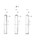
接触部材50は、内側に向けて張り出されたリップ部52を有している。リップ部52は、接触部材50の全周に亘って形成されており、リップ部52の内径は、ハンマ40の外筒部41の外径よりも小さい。また、リップ部52は、固定端よりも自由端の方がプレート36に近づく向きで傾斜している。さらに、リップ部52の自由端は、突部49と突部23とが係合している状態で、中心線Cに沿った方向で、ストッパ37とハンマ40との間に配置されている。
The
さらに、ハンマ40の外筒部41の外面に中心線Cに沿った方向の溝40aが設けられている。溝40aは、外筒部41であって、減速機24に近い方の端部から所定の長さに亘って設けられている。溝40aは、1本設けられていてもよいし、外筒部41の円周方向に、複数本設けられていてもよい。
Further, a
さらに、リップ部52の断面形状の一例を図3に示す。図3(A)は、リップ部52が、固定端から自由端に亘って同じ幅である例を示す。図3(B)は、リップ部52が、固定端から自由端に向けて幅が狭くなる例を示す。図3(C)は、リップ部52の内周端が円弧形状である例を示す。
Furthermore, an example of the cross-sectional shape of the
次に、打撃工具10の作用を説明する。電動モータ14が停止しているとき、圧縮ばね48に押圧されているハンマ40は、アンビル21に接触して停止している。電動モータ14に電力が供給されて回転軸15が回転すると、回転軸15のトルク、つまり回転力は減速機24のサンギヤ25に伝達される。サンギヤ25に回転力が伝達されると、リングギヤ26が反力要素となり、キャリヤ28が出力要素となる。すなわち、サンギヤ25の回転力がキャリヤ28に伝達されるとき、サンギヤ25の回転速度に対してキャリヤ28の回転速度が減速されることで、回転力が増幅される。
Next, the operation of the
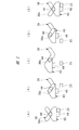
キャリヤ28に回転力が伝達されると、スピンドル35がキャリヤ28と共に一体回転する。スピンドル35の回転力は、スチールボール44を介してハンマ40に伝達される。ハンマ40の回転力は、図2(A)のように、突部49と突部23との係合力によりアンビル21に伝達され、アンビル21が回転する。アンビル21の回転力は先端工具53を介してボルトに伝達され、ボルトが対象物、例えば、木材にねじ込まれる。
When the rotational force is transmitted to the
その後、ボルトが木材にねじ込まれて、木材とボルトとの摩擦抵抗が増加し、先端工具53を回転させるために必要なトルクが高くなると、アンビル21が停止して、アンビル21とハンマ40とが相対回転し、スチールボール44とカム溝43との接触面で生じる反力により、ハンマ40がアンビル21から離れる向きで移動する。ハンマ40がアンビル21から離れる向きで移動することを後退と呼ぶ。
Thereafter, when the bolt is screwed into the wood, the frictional resistance between the wood and the bolt increases, and the torque necessary to rotate the
ハンマ40は、圧縮ばね48の押圧力に抗して中心線Cに沿って移動する。すると、図2(B)のようにスチールボール44が、カム溝39の端部39aに近づく向きで移動し、図4のように突部49と突部23とが解放され、ハンマ40の回転力はアンビル21に伝達されなくなる。
The
さらに、図5のように、ハンマ40の往復動作方向の端部、つまり、内筒部42の端部がストッパ37に衝突し、図2(C)のように、スチールボール44がカム溝39の端部39aに到達する。内筒部42の端部がストッパ37に衝突するとストッパ37が弾性変形し、ストッパ37は、ハンマ40がアンビル21から離れる向きで移動する際の運動エネルギを吸収する。ストッパ37は、ハンマ40が中心線Cに沿ってアンビル21から離れる向きで動作する範囲を規制する。
Further, as shown in FIG. 5, the end of the
さらに、ハンマ40の回転が継続されて、突部49が突部23を乗り越えると、ハンマ40をアンビル21から離れさせる向きの力よりも、圧縮ばね48がハンマ40に加える押圧力の方が高くなる。すると、図2(D)のようにスチールボール44がカム溝39,43に沿って転動することで、ハンマ40とスピンドル35とが相対回転し、かつ、ハンマ40はアンビル21に近づく向きで移動する。ハンマ40がアンビル21に近づく向きで移動することを前進と呼ぶ。
Further, when the rotation of the
その後、図2(E)のように、回転しているハンマ40の突部49が、停止しているアンビル21の突部23に衝突し、アンビル21に回転方向の打撃力が加えられる。なお、電動モータ14の回転軸15の回転方向を、ボルトを締め付ける際とは逆にすると、ボルトを緩めることができる。
Thereafter, as shown in FIG. 2E, the projecting
本実施形態の打撃工具10は、ボルトを締め付ける作業中、スチールボール44がカム溝39の端部39aに到達する前に、ハンマ40の内筒部42がストッパ37に接触し、ストッパ37がハンマ40の運動エネルギ、すなわち、衝撃力を収吸する。本実施形態の打撃工具10は、ストッパ37の中心線Cに沿った方向における厚さを設定して、スチールボール44がカム溝39の端部39aに到達する前に、ハンマ40の内筒部42の端面が、ストッパ37に接触するタイミングを調整してある。このため、スチールボール44がカム溝39の端部39aに衝突する際の異音、振動を抑制できる。また、スピンドル35の変形を抑制でき、打撃工具10の耐久性を向上できる。
In the
また、本実施形態の打撃工具10は、ハンマ40が後退すると、図4のように、ハンマ40の内筒部42がストッパ37に接触する前に、リップ部52がハンマ40の外筒部41の外周面に接触する。ハンマ40の内筒部42がストッパ37に接触する前に、リップ部52がハンマ40の外筒部41の外周面に接触するように、ストッパ37の端面よりもリップ部52の先端の方が、ハンマ40に近い位置に設けられている。
Further, in the
そして、リップ部52がハンマ40の外筒部41の外周面に接触して、リップ部52が撓むかまたは弾性変形し、リップ部52が外筒部41の外周面と擦れる。このため、ハンマ40が後退する際の運動エネルギが、外筒部41とリップ部52との摩擦力により低減される。
Then, the
つまり、ハンマ40が後退する速度を、リップ部52とハンマ40との接触部分の摩擦抵抗で低減できる。すなわち、リップ部52を含む接触部材50は、ハンマ40の半径方向でハンマ40の外側に位置しており、図5の状態において、ハンマ40の長手方向の領域に位置する。ハンマ40の長手方向の領域とは、ハンマ40の往復方向の領域である。言い換えると、ハンマ40が後退する際に、接触部材50は、外筒部41の外周面に接触し、ストッパ37のように外筒部41の端面には衝突しない。このため、接触部材50の寿命低下を抑制でき、かつ、ハンマ40の後退量が増加することを抑制でき、ハンマ40が後退する速度を低下できる。
That is, the speed at which the
また、リップ部52が外筒部41の外周面に接触してシール面を形成する。すると、内部Bであって、ハンマ40と減速機24との間に閉じられた空間Dが形成される。その空間Dの容積は、ハンマ40の後退量が増加することに伴い縮小され、空間Dの圧力が上昇する。そして、空間Dの圧力は、ハンマ40が後退する速度を低減させる抵抗となる。空間Dの空気圧がエアクッションとなる。空間Dが、本発明の圧力室に相当する。
Further, the
その結果、図5のようにハンマ40の内筒部42がストッパ37に衝突する際に、ストッパ37が受ける衝撃力を低減でき、打撃工具10の耐久性が向上する。なお、ストッパ37が受ける衝撃力は、例えば、ストッパ37の質量にストッパ37の移動速度を乗算して求めることができる。また、ストッパ37からキャリヤ28、軸受34、隔壁18を介して工具本体11に伝達される荷重を低減できる。したがって、工具本体11の振動を抑制できる。また、ハンマ40の外筒部41の外面に溝40aが設けられていると、ハンマ40がアンビル21から離れる向きで後退する際に、空間Dの空気が溝40aを通り排出される。
As a result, the impact force received by the
次に、ストッパ37が受ける打撃力を低減する構造の他の例を、図6及び図7に基づいて説明する。図6に示すスピンドル35の外周面に、環状の保持溝54が設けられている。保持溝54は、突部49と突部23とが噛み合っている状態で、中心線Cに沿った方向におけるストッパ37とカム溝39との間に設けられている。保持溝54はスピンドル35の全周に亘って設けられている。保持溝54に接触部材55が取り付けられている。接触部材55は、ゴム状弾性体により環状に一体成形されている。ハンマ40が停止している状態において、中心線Cに沿った方向でハンマ40とストッパ37との間に接触部材55が設けられている。接触部材55は、ハンマ40がアンビル21から離れる向きで後退する速度を、摩擦力により低下させる緩和機構である。
Next, another example of a structure for reducing the impact force received by the
図7(A)〜(C)は、接触部材55の断面形状の例である。図7(A)のように、中心線Cに沿った平面内における接触部材55の断面形状は円形にできる。また、図7(B)のように、中心線Cに沿った平面内における接触部材55の断面形状は半月形状にできる。図7(B)に示す接触部材55は、外周面が円弧形状に湾曲している。さらに、図7(C)のように、中心線Cに沿った平面内における接触部材55の断面形状を楔形にできる。図7(C)の接触部材55は、外側に角部が形成されている。一方、内筒部42の内径は、スピンドル35に取り付けられた接触部材55の外径以下に設定されている。
7A to 7C are examples of the cross-sectional shape of the
図6の打撃工具10はハンマ40が後退すると、ハンマ40の内筒部42がストッパ37に接触する前に、内筒部42の内周面が接触部材55に接触する。このため、ハンマ40が後退する過程で接触部材55が弾性変形し、内筒部42の内周面と接触部材55とが擦れる。このため、ハンマ40の運度エネルギの一部が摩擦熱に変換され、ハンマ40の移動速度を低下できる。したがって、内筒部42がストッパ37に衝突する際の衝撃力を低減でき、前記と同様の効果を得ることができる。なお、図6に示す打撃工具10において、図1、図2、図4、図5と同じ構成部分については、前述と同じ符号を付してあり、同様の作用が生じる。
In the
次に、ストッパ37が受ける打撃力を低減する構造の例を、図8及び図9に基づいて説明する。図8に示すスピンドル35に、カム溝39が形成されている部分の外径よりも大きな外径の大径部を有する大径部59が設けられている。大径部59の外周面にストッパ37が取り付けられている。また。ハンマ40の内筒部42には、スピンドル35の外周面に接触する部位よりも大径な内周面が設けられており、その内周面に接触部材57が取り付けられている。
Next, an example of a structure for reducing the striking force received by the
内筒部42の内周面は、大径部59の外径よりも大きい内径を有する。内筒部42の内周面には環状の保持溝が設けられており、保持溝に接触部材57が取り付けられている。接触部材57は、接触部材57はゴム状弾性体により一体成形されている。接触部材57は、中心線Cに沿った方向でカム溝43よりもストッパ37に近い位置に取り付けられている。接触部材57は、ハンマ40がアンビル21から離れる向きで後退する速度を、摩擦力により低下させる緩和機構である。
The inner peripheral surface of the
図9(A)〜(C)は、接触部材57の断面形状の例である。図9(A)のように、中心線Cに沿った平面内における接触部材57の断面形状を円形にすることができる。また、図9(B)のように、中心線Cに沿った平面内における接触部材57の断面形状を半月形状とすることもできる。図9(B)に示す接触部材57は、内周面が円弧形状に湾曲している。図9(C)のように、中心線Cに沿った平面内における接触部材57の断面形状を楔形にすることもできる。図9(C)の接触部材57は、内側に角部が形成されている。
9A to 9C are examples of the cross-sectional shape of the
図8の打撃工具10はハンマ40が後退すると、ハンマ40の内筒部42がストッパ37に接触する前に、接触部材57が大径部59に接触する。このため、ハンマ40が後退する過程で接触部材57が弾性変形し、大径部59の外周面と接触部材57とが擦れる。このため、ハンマ40の運度エネルギの一部が摩擦熱に変換され、ハンマ40の移動速度を低下できる。したがって、内筒部42がストッパ37に衝突する際の衝撃力を低減でき、前記と同様の効果を得ることができる。なお、図8に示す打撃工具10において、図1、図2、図4、図5と同じ構成部分については、前述と同じ符号を付してあり、同様の作用が生じる。
In the
上記した実施形態において、突部49と突部23とが噛み合っている状態で、ハンマ40がアンビル21から離れる向きで後退する領域が、本発明における第1の領域である。
これに対して、突部49と突部23とが噛み合っていない状態で、ハンマ40がアンビル21から離れる向きで後退する領域が、本発明における第2の領域である。さらに、各実施例に示された接触部材は、ハンマ40が第2の領域で後退し、かつ、最も後退した状態、つまり、ストッパ37には接触しない状態において、中心線Cに沿った方向でハンマ40の長さ方向の領域内に位置している。第2の領域は、アンビル21からの距離が第1の領域よりも遠い。
In the above-described embodiment, the region in which the
On the other hand, the region in which the
本発明は上記実施の形態に限定されるものではなく、その要旨を逸脱しない範囲で種々変更可能であることは言うまでもない。例えば、図1に示された接触部材50を取り付ける構造と、図6に示された接触部材55または図8に示された接触部材57を取り付ける構造と、を組み合わせることもできる。
It goes without saying that the present invention is not limited to the above-described embodiment, and various modifications can be made without departing from the scope of the invention. For example, the structure for attaching the
また、図1の接触部材50をハンマ40側に設け、工具本体11またはハンマケース13の内周面に、図8のような段差を設けることもできる。また、図1に示す接触部材50または溝40aの何れか一方を設けてもよい。すなわち、接触部材50が設けられていなくても、溝40aが設けられていれば、ハンマ40と減速機24との間に存在する空気の圧力が上昇し、ハンマ40が後退する速度を、空気の粘性により低下させることができる。また、本発明の接触部材は環状に構成する必要はなく、例えば周方向に複数個設けることもできる。また、先端工具は、ボルトを締め付けるドライバビットの他、木材、コンクリート等に穴をあけるドリルビットを含む。
Moreover, the
また、本発明の打撃工具は、アンビルに直接、先端工具を取り付ける構造の他、アンビルに、アダプタ、エクステンションバーを介して、間接的に先端工具を取り付ける構造を含む。さらに、本発明の打撃工具は、電動モータの回転軸の中心線が、ハンマの往復動作する中心線と交差している構造を含む。本発明は、ハンマの中心線と平行な面に接触部材が接触し、かつ、接触部材と平行な面とが擦れることで、摩擦力を生じる。中心線と平行な面は、ハンマの外周面、スピンドルの外周面、ハンマの内周面等を含む。 Moreover, the impact tool of this invention contains the structure which attaches a tip tool indirectly to an anvil via an adapter and an extension bar other than the structure which attaches a tip tool directly to an anvil. Furthermore, the impact tool of the present invention includes a structure in which the center line of the rotating shaft of the electric motor intersects the center line where the hammer reciprocates. In the present invention, the contact member comes into contact with a surface parallel to the center line of the hammer, and the friction force is generated by rubbing the surface parallel to the contact member. The surface parallel to the center line includes the outer peripheral surface of the hammer, the outer peripheral surface of the spindle, the inner peripheral surface of the hammer, and the like.
10…打撃工具、11…工具本体、21…アンビル、35…スピンドル、37…ストッパ、40…ハンマ、50,55,57…接触部材、53…先端工具、D…空間。
DESCRIPTION OF
Claims (12)
前記ハンマが往復動作可能に収容された工具本体と、
前記工具本体の内部に設けられ、前記ハンマが前記工具保持部材から離れる向きに後退することを緩和する緩和機構と、
を有する、打撃工具。 An impact tool that strikes a tool holding member that holds a tip tool with a hammer that reciprocates,
A tool body in which the hammer is reciprocally movable;
A relaxation mechanism that is provided inside the tool body and that relaxes the hammer retreating away from the tool holding member;
A striking tool.
前記緩和機構は、前記ハンマが前記ストッパに接触する前に、前記ハンマの後退を緩和する、請求項1に記載の打撃工具。 A stopper that is provided inside the tool body and contacts an end of the hammer in a reciprocating direction, and restricts a range in which the hammer moves backward;
The impact tool according to claim 1, wherein the relaxation mechanism relaxes the retraction of the hammer before the hammer contacts the stopper.
前記ハンマが往復動作可能に収容された工具本体と、
前記工具本体の内部に設けられて前記ハンマにおける往復動作方向の端部に接触し、前記ハンマが前記工具保持部材から離れる向きで動作する範囲を規制するストッパと、
前記工具本体の内部に設けられ、かつ、前記ハンマが前記ストッパに接触する前に、前記ハンマが前記工具保持部材から離れる向きで動作する速度を、摩擦または粘性により低減する緩和機構と、
を有する、打撃工具。 An impact tool that strikes a tool holding member that holds a tip tool with a hammer that reciprocates,
A tool body in which the hammer is reciprocally movable;
A stopper that is provided inside the tool body and contacts an end of the hammer in the reciprocating direction, and restricts a range in which the hammer moves in a direction away from the tool holding member;
A relaxation mechanism that is provided inside the tool body and that reduces the speed at which the hammer moves away from the tool holding member by friction or viscosity before the hammer contacts the stopper;
A striking tool.
前記ハンマが動作する速度を摩擦により低減する前記緩和機構は、前記工具本体の内面に設けられ、かつ、前記ハンマの外周面に接触する接触部材を含む、請求項3に記載の打撃工具。 The hammer has a substantially cylindrical shape surrounding a center line that reciprocates,
The impact tool according to claim 3, wherein the relaxation mechanism that reduces the speed at which the hammer operates by friction includes a contact member that is provided on an inner surface of the tool body and contacts an outer peripheral surface of the hammer.
前記ハンマは往復動作する中心線を囲む略円筒形状であり、
前記ハンマが動作する速度を摩擦により低減する前記緩和機構は、前記スピンドルの外周面に設けられ、かつ、前記ハンマの内周面に接触する接触部材を含む、請求項3に記載の打撃工具。 The hammer has a spindle mounted for reciprocal movement;
The hammer has a substantially cylindrical shape surrounding a center line that reciprocates,
The impact tool according to claim 3, wherein the relaxation mechanism that reduces the operating speed of the hammer by friction includes a contact member that is provided on the outer peripheral surface of the spindle and that contacts the inner peripheral surface of the hammer.
前記ハンマは往復動作する中心線を囲む略円筒形状であり、
前記ハンマが動作する速度を摩擦により低減する前記緩和機構は、前記ハンマの内周面に設けられ、かつ、前記スピンドルの外周面に接触する接触部材を含む、請求項3に記載の打撃工具。 The hammer has a spindle mounted for reciprocal movement;
The hammer has a substantially cylindrical shape surrounding a center line that reciprocates,
The impact tool according to claim 3, wherein the relaxation mechanism that reduces the operating speed of the hammer by friction includes a contact member that is provided on the inner peripheral surface of the hammer and that contacts the outer peripheral surface of the spindle.
前記ハンマが往復動作可能に収容された工具本体と、
前記工具本体の内部であって前記ハンマの半径方向で外側に設けられ、前記ハンマが前記工具保持部材から離れる方向に後退する際に前記ハンマに接触して前記ハンマが動作する速度を緩和する接触部材と、を有する、打撃工具。 An impact tool that strikes a tool holding member that holds a tip tool with a hammer that reciprocates,
A tool body in which the hammer is reciprocally movable;
A contact that is provided inside the tool body and outside in the radial direction of the hammer, and that reduces the speed at which the hammer operates by contacting the hammer when the hammer moves backward in a direction away from the tool holding member. A striking tool having a member.
前記ハンマが往復動作可能に収容された工具本体と、
前記工具本体の内部に設けられ、前記ハンマが前記工具保持部材から離れる向きに後退することを緩和する接触部材と、を有し、
前記接触部材は、前記ハンマが最も後退した状態において、往復方向における前記ハンマの長さ領域内に位置する、打撃工具。 A striking tool for striking a tool holding member that holds a tip tool with a substantially cylindrical hammer that reciprocates,
A tool body in which the hammer is reciprocally movable;
A contact member that is provided inside the tool body and that relieves the hammer from moving backward in a direction away from the tool holding member;
The contact tool is an impact tool that is located in a length region of the hammer in a reciprocating direction in a state where the hammer is most retracted.
Priority Applications (1)
| Application Number | Priority Date | Filing Date | Title |
|---|---|---|---|
| JP2013065154A JP2014188612A (en) | 2013-03-26 | 2013-03-26 | Impact tool |
Applications Claiming Priority (1)
| Application Number | Priority Date | Filing Date | Title |
|---|---|---|---|
| JP2013065154A JP2014188612A (en) | 2013-03-26 | 2013-03-26 | Impact tool |
Publications (1)
| Publication Number | Publication Date |
|---|---|
| JP2014188612A true JP2014188612A (en) | 2014-10-06 |
Family
ID=51835474
Family Applications (1)
| Application Number | Title | Priority Date | Filing Date |
|---|---|---|---|
| JP2013065154A Pending JP2014188612A (en) | 2013-03-26 | 2013-03-26 | Impact tool |
Country Status (1)
| Country | Link |
|---|---|
| JP (1) | JP2014188612A (en) |
Cited By (2)
| Publication number | Priority date | Publication date | Assignee | Title |
|---|---|---|---|---|
| JP2016159383A (en) * | 2015-02-27 | 2016-09-05 | 日立工機株式会社 | Impact tool |
| JP7459747B2 (en) | 2020-09-30 | 2024-04-02 | 工機ホールディングス株式会社 | Impact Tools |
Citations (6)
| Publication number | Priority date | Publication date | Assignee | Title |
|---|---|---|---|---|
| JPS531764A (en) * | 1976-04-30 | 1978-01-10 | Bourcier Carbon Christian | Gas buffer |
| JPH0355161U (en) * | 1989-09-29 | 1991-05-28 | ||
| JPH08215475A (en) * | 1995-02-13 | 1996-08-27 | Toshiba Corp | Damper device and washing machine |
| JP2002046078A (en) * | 2000-08-04 | 2002-02-12 | Hitachi Koki Co Ltd | Impact tool |
| JP2004030256A (en) * | 2002-06-26 | 2004-01-29 | Toshiba Tec Corp | Drawer device |
| JP2006316412A (en) * | 2005-05-10 | 2006-11-24 | Hokuden Kogyo Kk | Protrudable fence post |
-
2013
- 2013-03-26 JP JP2013065154A patent/JP2014188612A/en active Pending
Patent Citations (6)
| Publication number | Priority date | Publication date | Assignee | Title |
|---|---|---|---|---|
| JPS531764A (en) * | 1976-04-30 | 1978-01-10 | Bourcier Carbon Christian | Gas buffer |
| JPH0355161U (en) * | 1989-09-29 | 1991-05-28 | ||
| JPH08215475A (en) * | 1995-02-13 | 1996-08-27 | Toshiba Corp | Damper device and washing machine |
| JP2002046078A (en) * | 2000-08-04 | 2002-02-12 | Hitachi Koki Co Ltd | Impact tool |
| JP2004030256A (en) * | 2002-06-26 | 2004-01-29 | Toshiba Tec Corp | Drawer device |
| JP2006316412A (en) * | 2005-05-10 | 2006-11-24 | Hokuden Kogyo Kk | Protrudable fence post |
Cited By (2)
| Publication number | Priority date | Publication date | Assignee | Title |
|---|---|---|---|---|
| JP2016159383A (en) * | 2015-02-27 | 2016-09-05 | 日立工機株式会社 | Impact tool |
| JP7459747B2 (en) | 2020-09-30 | 2024-04-02 | 工機ホールディングス株式会社 | Impact Tools |
Similar Documents
| Publication | Publication Date | Title |
|---|---|---|
| RU2477211C2 (en) | Impact tool | |
| US8490714B2 (en) | Impact wrench | |
| JP4501757B2 (en) | Impact tools | |
| JP6341283B2 (en) | Impact tool | |
| RU2010147805A (en) | SHOCK MECHANISM | |
| US10870189B2 (en) | Percussion mechanism device, in particular for an impact wrench | |
| JP2007050454A (en) | Impact tool | |
| JP2006315093A (en) | Impact tool | |
| JP2014188612A (en) | Impact tool | |
| JP2013208678A (en) | Impact tool | |
| EP2415563B9 (en) | Impact tool | |
| JP6455227B2 (en) | Impact tool | |
| JP2013022691A (en) | Impact rotary tool | |
| JP2009172732A (en) | Impact rotary tool | |
| JP2008073793A (en) | Impact tool | |
| WO2014208058A1 (en) | Striking tool | |
| JP2005066728A (en) | Impact rotating tool | |
| JP6160771B2 (en) | Hammering machine | |
| JP2015188953A (en) | Impact work machine | |
| JP2015120206A (en) | Impact tool | |
| JP7094036B2 (en) | Impact tool | |
| JP2007054934A (en) | Connecting tool and impact tool provided with the same | |
| JP7400591B2 (en) | work equipment | |
| US20170014983A1 (en) | Chiseling handheld power tool | |
| WO2018159171A1 (en) | Impact work machine |
Legal Events
| Date | Code | Title | Description |
|---|---|---|---|
| A621 | Written request for application examination |
Free format text: JAPANESE INTERMEDIATE CODE: A621 Effective date: 20150930 |
|
| A977 | Report on retrieval |
Free format text: JAPANESE INTERMEDIATE CODE: A971007 Effective date: 20160706 |
|
| A131 | Notification of reasons for refusal |
Free format text: JAPANESE INTERMEDIATE CODE: A131 Effective date: 20160712 |
|
| A02 | Decision of refusal |
Free format text: JAPANESE INTERMEDIATE CODE: A02 Effective date: 20170131 |