JP2014184591A - Printer - Google Patents
Printer Download PDFInfo
- Publication number
- JP2014184591A JP2014184591A JP2013059561A JP2013059561A JP2014184591A JP 2014184591 A JP2014184591 A JP 2014184591A JP 2013059561 A JP2013059561 A JP 2013059561A JP 2013059561 A JP2013059561 A JP 2013059561A JP 2014184591 A JP2014184591 A JP 2014184591A
- Authority
- JP
- Japan
- Prior art keywords
- head unit
- printing apparatus
- carriage
- slide rail
- head
- Prior art date
- Legal status (The legal status is an assumption and is not a legal conclusion. Google has not performed a legal analysis and makes no representation as to the accuracy of the status listed.)
- Granted
Links
Images


Classifications
-
- B—PERFORMING OPERATIONS; TRANSPORTING
- B41—PRINTING; LINING MACHINES; TYPEWRITERS; STAMPS
- B41J—TYPEWRITERS; SELECTIVE PRINTING MECHANISMS, i.e. MECHANISMS PRINTING OTHERWISE THAN FROM A FORME; CORRECTION OF TYPOGRAPHICAL ERRORS
- B41J25/00—Actions or mechanisms not otherwise provided for
- B41J25/34—Bodily-changeable print heads or carriages
-
- B—PERFORMING OPERATIONS; TRANSPORTING
- B41—PRINTING; LINING MACHINES; TYPEWRITERS; STAMPS
- B41J—TYPEWRITERS; SELECTIVE PRINTING MECHANISMS, i.e. MECHANISMS PRINTING OTHERWISE THAN FROM A FORME; CORRECTION OF TYPOGRAPHICAL ERRORS
- B41J2/00—Typewriters or selective printing mechanisms characterised by the printing or marking process for which they are designed
- B41J2/005—Typewriters or selective printing mechanisms characterised by the printing or marking process for which they are designed characterised by bringing liquid or particles selectively into contact with a printing material
- B41J2/01—Ink jet
- B41J2/17—Ink jet characterised by ink handling
- B41J2/175—Ink supply systems ; Circuit parts therefor
- B41J2/17503—Ink cartridges
- B41J2/1752—Mounting within the printer
-
- B—PERFORMING OPERATIONS; TRANSPORTING
- B41—PRINTING; LINING MACHINES; TYPEWRITERS; STAMPS
- B41J—TYPEWRITERS; SELECTIVE PRINTING MECHANISMS, i.e. MECHANISMS PRINTING OTHERWISE THAN FROM A FORME; CORRECTION OF TYPOGRAPHICAL ERRORS
- B41J2/00—Typewriters or selective printing mechanisms characterised by the printing or marking process for which they are designed
- B41J2/005—Typewriters or selective printing mechanisms characterised by the printing or marking process for which they are designed characterised by bringing liquid or particles selectively into contact with a printing material
- B41J2/01—Ink jet
- B41J2/17—Ink jet characterised by ink handling
- B41J2/175—Ink supply systems ; Circuit parts therefor
- B41J2/17503—Ink cartridges
- B41J2/17506—Refilling of the cartridge
- B41J2/17509—Whilst mounted in the printer
-
- B—PERFORMING OPERATIONS; TRANSPORTING
- B41—PRINTING; LINING MACHINES; TYPEWRITERS; STAMPS
- B41J—TYPEWRITERS; SELECTIVE PRINTING MECHANISMS, i.e. MECHANISMS PRINTING OTHERWISE THAN FROM A FORME; CORRECTION OF TYPOGRAPHICAL ERRORS
- B41J2/00—Typewriters or selective printing mechanisms characterised by the printing or marking process for which they are designed
- B41J2/005—Typewriters or selective printing mechanisms characterised by the printing or marking process for which they are designed characterised by bringing liquid or particles selectively into contact with a printing material
- B41J2/01—Ink jet
- B41J2/17—Ink jet characterised by ink handling
- B41J2/175—Ink supply systems ; Circuit parts therefor
- B41J2/17503—Ink cartridges
- B41J2/17513—Inner structure
Landscapes
- Ink Jet (AREA)
- Accessory Devices And Overall Control Thereof (AREA)
- Common Mechanisms (AREA)
Abstract
Description
本発明は、複数の印刷ヘッドを搭載したヘッドユニットが装着される印刷装置に関するものである。 The present invention relates to a printing apparatus to which a head unit equipped with a plurality of print heads is mounted.
従来、大型のプリンターでは、数多くの液滴吐出ヘッド(印刷ヘッド)を単一のキャリッジ(ヘッドプレート)に搭載した大型のヘッドユニットが必要になると共に、大型のヘッドユニットの交換作業を行う必要がある。
このような大型のキャリッジを効率良く運搬およびセットするために、複数の液滴吐出ヘッドと、複数の液滴吐出ヘッドを裏面側に突出させて搭載したキャリッジと、キャリッジの表面に設けられキャリッジを手持ちするための左右一対のハンドルと、を備えたヘッドユニットが知られている(特許文献1)。ヘッドユニットは、セットステージ(キャリッジ)への導入に際して、先ずセットステージよりも幾分高い仮置き台に載置される。オペレーターは、キャリッジの表面に設けられた左右一対のハンドルを握って、ヘッドユニット先端を傾けて仮置き台上をスライドさせ、先端をセットステージのストッパーに突き当ててから更に下降させてセットステージに載せ込むようにしている。また、左右一対のハンドルを把持することでヘッドユニットをほぼセット姿勢のまま持ち運びすることができるため、大型のヘッドユニットであっても安定且つ安全に着脱することができる。
Conventionally, a large printer requires a large head unit in which a large number of droplet discharge heads (print heads) are mounted on a single carriage (head plate), and it is necessary to replace the large head unit. is there.
In order to efficiently transport and set such a large carriage, a plurality of droplet discharge heads, a carriage on which a plurality of droplet discharge heads are protruded on the back side, a carriage provided on the surface of the carriage, A head unit including a pair of left and right handles for hand-held is known (Patent Document 1). When the head unit is introduced into the set stage (carriage), it is first placed on a temporary table that is somewhat higher than the set stage. The operator holds a pair of left and right handles provided on the surface of the carriage, tilts the tip of the head unit and slides it on the temporary table, lowers the tip against the stopper of the set stage, and then lowers it further to the set stage. I try to load it. Further, since the head unit can be carried in a substantially set posture by gripping the pair of left and right handles, even a large head unit can be attached and detached stably and safely.
しかしながら、上記のようなヘッドユニットは、先端部を下げるように傾斜させた状態でスライドさせながらセットステージに載せ込むため、ヘッドユニットの装着が完了するまでオペレーターがハンドルを把持してヘッドユニットの傾斜姿勢を維持する必要がある。このため、セットステージの上側に着脱作業のための大きなスペースを要し、装置が大型化する問題があった。
また、床面に対して並行でない様々な角度でヘッドユニットを設置する場合や高い位置に設置する場合、作業姿勢が不安定となり、着脱作業が煩雑となる問題があった。
However, since the head unit as described above is mounted on the set stage while being slid so that the tip is lowered, the operator holds the handle until the installation of the head unit is completed, and the head unit is tilted. It is necessary to maintain posture. For this reason, a large space for attaching and detaching work is required on the upper side of the set stage, and there is a problem that the apparatus becomes large.
Further, when the head unit is installed at various angles not parallel to the floor surface or when installed at a high position, there is a problem that the working posture becomes unstable and the attaching / detaching work becomes complicated.
本発明は、印刷ヘッドを搭載したヘッドユニットを、キャリッジに対して簡単且つ円滑に着脱することができる印刷装置を提供するものである。 The present invention provides a printing apparatus in which a head unit having a print head mounted thereon can be easily and smoothly attached to and detached from a carriage.
本発明は、上述の課題の少なくとも一部を解決するためになされたものであり、以下の形態または適用例として実現することが可能である。 SUMMARY An advantage of some aspects of the invention is to solve at least a part of the problems described above, and the invention can be implemented as the following forms or application examples.
[適用例1]本適用例に係る印刷装置は、印刷ヘッドをヘッドプレートに搭載したヘッドユニットと、前記ヘッドユニットを保持するキャリッジと、を備えた印刷装置であって、前記キャリッジは、前記ヘッドユニットをスライド式に着脱する際に前記ヘッドユニットのガイド面となる連結プレートを有し、前記連結プレートには、前記着脱する方向に延伸するスライドレールが設けられ、前記ヘッドユニットには、前記スライドレールに係合する係合突起部が設けられていることを特徴とする。 Application Example 1 A printing apparatus according to this application example includes a head unit having a print head mounted on a head plate, and a carriage that holds the head unit, and the carriage includes the head A connecting plate that serves as a guide surface for the head unit when the unit is detachably mounted; and the connecting plate is provided with a slide rail that extends in the attaching / detaching direction. The head unit includes the slide An engagement protrusion that engages with the rail is provided.
本適用例によれば、キャリッジのスライドレールにヘッドユニットの先端付近にある係合突起部をあてがい、ヘッドユニットをスライドレールに沿って押し込むことで、ヘッドユニットをキャリッジに装着することができる。また、逆の手順で、ヘッドユニットをキャリッジからスライドレールに沿って引抜くようにすれば、ヘッドユニットをキャリッジから離脱させることができる。すなわち、印刷ヘッドを搭載したヘッドユニットを、キャリッジに対し簡単且つ円滑に着脱することができる。この場合、ヘッドユニットをスライド式で着脱させる構造であるため、キャリッジの上側にヘッドユニットを着脱させるための大きな空間を必要としない。 According to this application example, it is possible to attach the head unit to the carriage by applying the engaging protrusion near the tip of the head unit to the slide rail of the carriage and pushing the head unit along the slide rail. If the head unit is pulled out along the slide rail from the carriage in the reverse procedure, the head unit can be detached from the carriage. That is, the head unit on which the print head is mounted can be easily and smoothly attached to and detached from the carriage. In this case, since the head unit is slidably attached and detached, a large space for attaching and detaching the head unit is not required on the upper side of the carriage.
この場合、キャリッジは、ヘッドユニットの着脱軌跡をガイドするスライドレールと、スライド方向の一方の側において、装着状態のヘッドユニットの位置を位置決めする第1位置決め手段と、スライド方向の他方の側において、装着状態のヘッドユニットの位置を位置決めする第2位置決め手段と、を有していることが好ましい。 In this case, the carriage includes a slide rail that guides the attachment / detachment locus of the head unit, a first positioning unit that positions the mounted head unit on one side in the sliding direction, and the other side in the sliding direction. And a second positioning means for positioning the head unit in the mounted state.
[適用例2]上記適用例に記載の印刷装置において、前記スライドレールの軌道が、前記着脱する方向と交差する方向に屈曲する屈曲部を有していることが好ましい。 Application Example 2 In the printing apparatus according to the application example described above, it is preferable that the track of the slide rail has a bent portion that bends in a direction intersecting the attaching / detaching direction.
本適用例によれば、ヘッドユニットの着脱時に描く軌跡上に、装置の他構成要素による障害がある場合にも、それらを避ける軌跡にスライドレールを形成する事ができ、装置構成に柔軟に対応する事が可能になる。 According to this application example, even if there are obstacles due to other components of the device on the trajectory drawn when the head unit is attached / detached, the slide rail can be formed on the trajectory to avoid them and flexibly support the device configuration It becomes possible to do.
[適用例3]上記適用例に記載の印刷装置において、前記スライドレールが、前記ヘッドユニットの装着位置から取り外し方向に向かう途中で複数方向に分岐して形成されていることが好ましい。 Application Example 3 In the printing apparatus according to the application example described above, it is preferable that the slide rail is formed to be branched in a plurality of directions on the way from the mounting position of the head unit in the removal direction.
本適用例によれば、適用例2と同様にヘッドユニットの着脱時に描く軌跡上に、装置の他構成要素による障害があり、且つキャリッジが複数存在する場合において、それらを避ける軌跡を同じ連結プレートに形成することで、装置構成への柔軟な対応と、部品の共通化によるコストダウンを実現する事が可能になる。 According to this application example, in the same manner as in Application Example 2, when there are obstacles due to other components of the apparatus on the locus drawn when the head unit is attached and detached and there are a plurality of carriages, the locus to avoid them is the same connecting plate. By forming them in a flexible manner, it is possible to realize a flexible response to the device configuration and cost reduction by sharing parts.
[適用例4]上記適用例に記載の印刷装置において、前記係合突起部は、円筒形状を呈し、前記ヘッドユニットに回転可能に設けられていることが望ましい。 Application Example 4 In the printing apparatus according to the application example described above, it is preferable that the engagement protrusion has a cylindrical shape and is provided rotatably on the head unit.
本適用例によれば、連結プレートに形成するスライドレールに沿ってスライドする場合に、スムーズに動作させる事ができる。更に、適用例2にあるようにスライドレールが途中で屈曲している場合にも円筒状であれば引掛かる事がなく操作性を向上する事が可能になる。 According to this application example, when sliding along the slide rail formed on the connecting plate, it can be operated smoothly. Furthermore, even when the slide rail is bent halfway as in Application Example 2, it is possible to improve the operability without being caught if it is cylindrical.
[適用例5]上記適用例に記載の印刷装置において、前記係合突起部が、前記着脱する方向に対して複数並設されていることが望ましい。 Application Example 5 In the printing apparatus according to the application example described above, it is preferable that a plurality of the engaging protrusions are arranged in parallel in the attaching / detaching direction.
本適用例によれば、連結プレートに形成するスライドレールに沿ってスライドしている途中の状態に、スライド方向を自動的に保持する事ができ、ヘッドユニットの姿勢を制限し、他の構成要素にぶつけてしまう事を防止する事が可能になる。 According to this application example, the sliding direction can be automatically held in the middle of sliding along the slide rail formed on the connecting plate, the posture of the head unit is limited, and other components It is possible to prevent hitting.
[適用例6]上記適用例に記載の印刷装置において、前記係合突起部は、前記ヘッドユニットとの付け根側に先端側よりも細い括れ部を有し、前記スライドレールは、前記括れ部を有する前記係合突起部が勘合する形状にて形成されていることが望ましい。 Application Example 6 In the printing apparatus according to the application example described above, the engagement protrusion has a narrowed portion that is narrower than the tip side on the base side with the head unit, and the slide rail includes the narrowed portion. It is desirable that the engaging protrusions have a shape that fits.
本適用例によれば、キャリッジにヘッドユニットを着脱する作業の内、連結プレートに形成するスライドレールに係合突起部が係合した状態を補助する補助プレートを用いる事なく、係合状態を保持できるので、小キャリッジの小型化が可能になる。 According to this application example, the engagement state can be maintained without using the auxiliary plate that assists the state in which the engagement protrusion is engaged with the slide rail formed on the connecting plate during the operation of attaching and detaching the head unit to the carriage. Therefore, it is possible to reduce the size of the small carriage.
[適用例7]上記適用例に記載の印刷装置において、前記係合突起部が、前記キャリッジに対して前記ヘッドユニットを装着する際に前記ヘッドユニットの装着先端側の近傍に設けられていることが望ましい。 Application Example 7 In the printing apparatus according to the application example described above, the engagement protrusion is provided in the vicinity of a mounting tip side of the head unit when the head unit is mounted on the carriage. Is desirable.
本適用例によれば、キャリッジにヘッドユニットを着脱する作業の内、連結プレートに形成するスライドレールに係合突起部が係合している状態をより長い間保持する事ができ、適用例1〜6の効果を最大に発揮する事が可能になる。 According to this application example, the state in which the engagement protrusion is engaged with the slide rail formed on the connection plate can be held for a longer period of time in the operation of attaching and detaching the head unit to the carriage. It is possible to maximize the effect of ~ 6.
[適用例8]上記適用例に記載の印刷装置において、前記スライドレールは、前記ヘッドユニットが装着されて位置決めされるときに前記係合突起部が位置する部分に、他の部分より幅が広い幅広部を有していることが望ましい。 Application Example 8 In the printing apparatus according to the application example described above, the slide rail is wider in a portion where the engagement protrusion is positioned when the head unit is mounted and positioned than in other portions. It is desirable to have a wide portion.
本適用例によれば、キャリッジにヘッドユニットが最終的に位置決めされる直前より、スライドレールと係合突起部による規制を解除して、位置決め手段による勘合を優先させる事ができ、最終的な位置決めに支障を来たさないようにする事が可能になる。 According to this application example, the restriction by the slide rail and the engagement protrusion can be released immediately before the head unit is finally positioned on the carriage, and the fitting by the positioning means can be prioritized. It will be possible to avoid any trouble.
[適用例9]上記適用例に記載の印刷装置において、前記スライドレールおよびそれと係合する前記係合突起部とが、前記ヘッドユニットの両側に配置されていることが望ましい。 Application Example 9 In the printing apparatus according to the application example described above, it is preferable that the slide rail and the engagement protrusion engaged with the slide rail are disposed on both sides of the head unit.
本適用例によれば、キャリッジに対するヘッドユニットの着脱の際に、ヘッドユニットが両側からより安定して保持されるので、上記適用例の効果をより大きく得ることが可能になる。 According to this application example, since the head unit is more stably held from both sides when the head unit is attached to and detached from the carriage, the effect of the application example can be further increased.
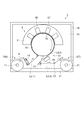
以下、添付の図面を参照して、本発明の一実施形態に係る印刷装置としてのインクジェット装置について説明する。図1は、実施形態に係るインクジェット装置の正面図である。
図1に示すインクジェット装置1は、周方向に複数の印刷ヘッドを配置したセンタードラム式の印刷装置であり、リールツーリールで供給した長尺の記録媒体に、UVインク(紫外線硬化型インク)を用いて印刷を実施する。記録媒体としては、例えばラベル用のフィルムや用紙等のシート状のものであって、各種幅および厚みの異なるものを印刷対象としている。なお、以降の説明では、図1において紙面を貫通する方向を前後とし、手前側を「前」、奥側を「後」とする。具体的には、後述する回転ドラム61の回転軸(ドラム軸62)の延在方向を前後とし、後述するドラムモーター64から回転ドラム61へ向かう方向を手前方向(手前側)、回転ドラム61からドラムモーター64へ向かう方向を奥方向(奥側)とする。また、記録媒体の搬送経路において、後述する媒体供給装置6側を「上流側」、後述する媒体回収装置7側を「下流側」とする。
Hereinafter, an inkjet apparatus as a printing apparatus according to an embodiment of the present invention will be described with reference to the accompanying drawings. FIG. 1 is a front view of the ink jet apparatus according to the embodiment.
An ink jet apparatus 1 shown in FIG. 1 is a center drum type printing apparatus in which a plurality of print heads are arranged in a circumferential direction, and UV ink (ultraviolet curable ink) is applied to a long recording medium supplied reel-to-reel. To perform printing. The recording medium is, for example, a sheet-like material such as a label film or paper, and has various widths and thicknesses to be printed. In the following description, the direction penetrating the paper surface in FIG. 1 is front and rear, the front side is “front”, and the back side is “rear”. Specifically, the extending direction of the rotating shaft (drum shaft 62) of the rotating drum 61 (described later) is the front and rear, the direction from the drum motor 64 (described later) toward the
(実施形態1)
図1の全体図に示すように、インクジェット装置1は、インクジェット方式で記録媒体Aに印刷を行うセンタードラム式の印刷部2と、印刷部2に記録媒体Aを供給し且つ印刷済みの記録媒体Aを回収するリールツーリール方式の媒体供給・回収装置3と、これら構成装置を統括制御する制御装置(図示省略)と、を備えている。媒体供給・回収装置3は、印刷部2に記録媒体Aを供給する媒体供給装置6と、印刷部2から記録媒体Aを回収する媒体回収装置7と、を有している。一方、印刷部2および媒体供給・回収装置3に構成した記録媒体Aの媒体送り経路Lは、媒体供給装置6から印刷部2に至る供給送り経路L1と、印刷部2に構成した円に近い円弧状の印刷送り経路L2と、印刷部2から媒体回収装置7に至る回収送り経路L3と、を有している。
(Embodiment 1)
As shown in the overall view of FIG. 1, an inkjet apparatus 1 includes a center drum
供給送り経路L1を介して、媒体供給装置6から繰り出すようにして供給された記録媒体Aは、印刷部2において印刷送り経路L2に沿って送られ、この部分で印刷に供される。また、印刷が完了した記録媒体Aは、回収送り経路L3を介して媒体回収装置7により巻き取るようにして回収される。
The recording medium A supplied from the
媒体供給装置6は、ロール状に巻回した記録媒体Aを繰り出す繰出しリール11と、繰出しリール11を繰出し回転させる繰出しモーター(図示省略)と、繰出しリール11の下流側に配設され、記録媒体Aを幅方向に位置決めしつつ印刷部2に送り込むステアリングユニット14と、を備えている。媒体供給装置6は、制御装置により印刷部2に同期して繰出しモーターを駆動すると、繰出しリール11から記録媒体Aが繰出され、供給送り経路L1に沿って送られる。
The
一方、媒体回収装置7は、印刷済みの記録媒体Aをロール状に巻き取る巻取りリール21と、巻取りリール21を巻取り回転させる巻取りモーター(図示省略)と、巻取りリール21の上流側に配設され、記録媒体Aにバックテンションを付与するバックテンションローラー23と、バックテンションローラー23の上流側に配設され、印刷部2から送り出された記録媒体AがUターンして送られるように、回収送り経路L3を経路変更する折返しユニット25と、を備えている。媒体回収装置7は、制御装置により印刷部2に同期して巻取りモーターを駆動すると、記録媒体Aは印刷部2から送出され、回収送り経路L3に沿って送られる。
On the other hand, the
図1に示すように、印刷部2は、回転ドラム61を有し、印刷送り経路L2に沿って記録媒体Aを送る媒体送り機構41と、それぞれが複数の印刷ヘッド76を有し、印刷送り経路L2に臨むように、回転ドラム61に対し放射状に配設した複数のキャリッジユニット42と、上記の回収送り経路L3に臨み、記録媒体AのUVインクを硬化させる本硬化用のUV照射ユニット44を備えている。また、印刷部2は、全体としてチャンバー(図示省略)に覆われている。
As shown in FIG. 1, the
図2に示すように、装置フレーム46は、機台となるベースフレーム51と、ベースフレーム51の後半部に立設したメインフレーム52と、メインフレーム52の前面に広く設けた板状のサブフレーム53と、サブフレーム53を介しメインフレーム52の前部に配設したチャンバーフレーム54と、を有している。メインフレーム52およびチャンバーフレーム54が構成する各面には、それぞれ壁体(図示省略)が取り付けられており、これらによって印刷部2全体を覆うチャンバーを構成する。すなわち、印刷部2は、このチャンバーによって、その内部の温度および清浄度を管理している。なお、チャンバーフレーム54とベースフレーム51との間には、所定の間隙が設けられており、この間隙において記録媒体Aの給紙および排紙が行われる。
As shown in FIG. 2, the
図1において、大キャリッジ81をベースとして回転ドラム61に対し放射状に配設された複数のキャリッジユニット42は、インク色別のユニットであり、印刷送り経路L2の始端側から終端側に向って、シアン(C)、マゼンタ(M)、イエロー(Y)、ブラック(Bk)の順で、周方向にほぼ等間隔で配設されている。詳細は後述するが、各キャリッジユニット42には、複数の印刷ヘッド76が搭載されている。そして、印刷送り経路L2に沿って印刷送りされてゆく記録媒体Aに、各色のキャリッジユニット42が順に臨むことになり、記録媒体Aに印刷データに基づく所望のカラー印刷が行われる。
In FIG. 1, a plurality of
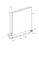
次に、印刷部2各部の詳細な構成について、図面を参照して説明する。図3は、キャリッジユニット廻りの断面図である。また、図4は、印刷ヘッドの斜視図である。また、図5は、ヘッドユニットの斜視図である。また、図6は、小キャリッジ82廻りの斜視図である。
図3において、各キャリッジユニット42は、上記のサブフレーム53(図1、図2を参照)に固定された大キャリッジ81の回転ドラム61の外周面の法線方向において、大キャリッジ81にスライド自在に支持された箱型フレーム形式の小キャリッジ82と、小キャリッジ82に装着され、複数の印刷ヘッド76を搭載したヘッドユニット83と、小キャリッジ82を介してヘッドユニット83を回転ドラム61の外周面の法線方向に進退させるZ軸移動機構84と、小キャリッジ82に搭載され、複数の印刷ヘッド76に吐出波形を印加するヘッド制御基板モジュール(図示省略)と、を備えている。また、各キャリッジユニット42は、小キャリッジ82に設けられ、記録媒体Aに着弾させたUVインクを仮硬化させるピニングユニット86と、大キャリッジ81の外側面に支持され、複数の印刷ヘッド76にUVインクを供給するサブタンクユニット(図示省略)と、を備えている。
Next, the detailed configuration of each part of the
In FIG. 3, each
Z軸移動機構84は、例えば、モーター駆動のカム機構を用いて構成されている。Z軸移動機構84は、厚みの異なる記録媒体Aに対し、印刷ヘッド76と記録媒体Aとのギャップ調整を行う。
The Z-
本実施形態のインクジェット装置1で使用するUVインクは、その粘性が、高い温度依存性(温度が高くなると粘性が低下する)を有している。このため、図示では省略したが、上記のサブタンクユニット、複数の印刷ヘッド76およびサブタンクユニットから複数の印刷ヘッド76に至るインク流路(主チューブ、マニホールド、個別チューブ)は、ヒーター等により温度調整されている。例えば、UVインクを40℃程度に昇温して吐出する。 The UV ink used in the inkjet apparatus 1 of the present embodiment has a high temperature dependency (viscosity decreases as the temperature increases). Therefore, although not shown in the drawing, the temperature of the sub tank unit, the plurality of print heads 76, and the ink flow paths (main tube, manifold, individual tube) from the sub tank unit to the plurality of print heads 76 are adjusted by a heater or the like. ing. For example, the UV ink is heated to about 40 ° C. and discharged.
図4に示すように、インクジェット式の印刷ヘッド76は、そのノズル面91に相互に並行な複数の吐出ノズル92から成る2列のノズル列93を有している。ヘッドプレート94において、複数の印刷ヘッド76は、前後方向において千鳥に配設され、これを印字タイミング等の画像処理手段により、連続した長尺ヘッドとして扱う事が可能となる。なお、この配列パターンは一例であり、印刷ヘッド76の個数や列数、さらに配列パターンは任意である。
As shown in FIG. 4, the ink
次に、本発明の特徴的部分であるヘッドユニット83および小キャリッジ82について詳細に説明する。先ず、ヘッドユニット83、および小キャリッジ82の構成を順に説明した後に、キャリッジユニット42における小キャリッジ82へのヘッドユニット83の着脱方法について説明をする。
Next, the
図5において、ヘッドユニット83は、ヘッドプレート94と、ヘッドプレート94に組み付けられた複数の印刷ヘッド76とを備えている。本実施形態では、ヘッドプレート94に四つの印刷ヘッド76が組み付けられた状態を図示しているが、印刷ヘッド76の数は任意に決定することができる。また、ヘッドプレートには図示しないインク流路が設けられ、そのインク流路は対応する印刷ヘッド76に接続されている。更に、ヘッドプレート94の上部には箱状のカバーフレーム95が固定されている。カバーフレーム95内部にはヘッド基板(不図示)が収容され、このヘッド基板は印刷ヘッド76に電気的に接続されている。これらをまとまった状態でヘッドユニット83として扱い、キャリッジ内部に位置決め機構を介して搭載されている。
ヘッドプレート94の前端片側面部には、係合突起部147が設置されている。本実施形態では二つの係合突起部147が所定の間隔を空けて設置されている。各係合突起部147は、その外周部が回転可能となっており、他部品との接触時には摩擦抵抗が軽減され軽い操作を可能にしている。尚、係合突起部147を二つ設けた構成に限らず、一つでもよく、または、三つ以上設ける構成であっても構わない。
In FIG. 5, the
An engaging
図6において、小キャリッジ82は、上記の大キャリッジ81の前面に配設されている。小キャリッジは、フロントプレート151と、フロントプレート151の幅方向両端部からブラケット様に手前側(他方の側)に突設した一対のサイドプレートである連結プレート152および補助プレート156と、連結プレート152と補助プレート156との下端部間に取り付けた方形枠状の支持ベース153と、を備えている。
フロントプレート151は、上下方向に細長い長方形状を呈しており、このフロントプレート151の背面にはガイドレール(不図示)が固定されている。そして、ガイドレールが大キャリッジ81に設けられたスライダー154にスライド自在に支持されている。これにより、小キャリッジ82が、上記Z軸移動機構84(図3参照)により、大キャリッジ81に対して回転ドラム61の外周面の法線方向(図1、図3参照)に昇降可能な状態で支持されている。また、一対のサイドプレートを成す連結プレート152および補助プレート156は、それぞれ上辺を前下がりの傾斜辺とする片台形状を為しており、フロントプレート151から前方に並行に張り出している。
連結プレート152および補助プレート156の正面端(フロントプレート151の取付け側と反対側)にはリアプレート157が固定されている。リアプレート157のフロントプレート151側と反対側には一対のX係合部158が設けられている。
以上、述べた構成の小キャリッジ82は、リアプレート157、フロントプレート151、連結プレート152、および補助プレート156により一体の略箱型に形成されており、この箱型の中にヘッドユニット83を収めることができるようになっている。
In FIG. 6, the
The
A
The
上記の小キャリッジ82において、連結プレート152には、ヘッドユニット83の装着をガイドするスライドレール146が形成されている。ヘッドユニット83はスライドレール146に沿って、スライドレール146の延在方向にスライドして案内される。また、図示はしないが、小キャリッジ82内のリアプレート157とフロントプレート151にはヘッドユニット83を位置決め固定するホールド部材が備えられている。
In the
ここで、図面を参照して、小キャリッジ82へのヘッドユニット83の着脱動作について説明する。図7は、小キャリッジ82に対するヘッドユニット83の着脱動作を模式的に示す説明図である。
図7(a)において、作業者はまず、ヘッドユニット83のカバーフレーム95を把持してヘッドユニット83を小キャリッジ82に運び込み、ヘッドプレート94の先端付近に設けられた2つの係合突起部147を、連結プレート152に設けられたスライドレール146の前端開口部146aに勘合させ、スライドレール146の延在方向にスライドさせて押し込んでゆく(図7(b)参照)。
このとき、係合突起部147が2つともスライドレール146に完全に入った時点から、ヘッドユニット83はスライドレール146の角度によって角度を規制され、その姿勢を保持可能となる。この効用により、ヘッドユニット83の装着時に、リアプレート157に印刷ヘッド76を接触させて壊すなどの不具合を防止することができる。また、作業者が、ヘッドユニット83の装着時(離脱時)に、把持しているヘッドユニット83を手を滑らせて落下させるなどの不具合を回避できる。
Here, with reference to the drawings, the operation of attaching and detaching the
In FIG. 7A, the operator first holds the
At this time, the
次に、図7(c)において、ヘッドユニット83を、スライドレール146に案内させてスライドさせながら更に押し込んで行くと、ヘッドプレート94の前方位置決め面148がフロントプレート151に取り付けてあるY係合部163に突き当たるようにして係合すると共に、Z方向、X方向の位置決め面148もほぼ同時に、それぞれZ係合部201、X係合部158に押し当てられるようにして係合する。さらに、ヘッドプレート94は、小キャリッジ82に備わる固定部材(図示省略)を用いて位置決め状態から動かないようにする小キャリッジ82に固定される(図7(d)参照)。
Next, in FIG. 7C, when the
尚、スライドレール146は、ヘッドユニット83が前述した小キャリッジ82に備わる位置決め係合部(X係合部158、Y係合部163、Z係合部201)に掛かる位置まで装着されたときに係合突起部147が位置する部分の溝幅を広くしておくとよい。このようにすることにより、スライドレール146による係合突起部147の規制が、小キャリッジ82に対するヘッドユニット83の位置決めに影響しないようにすることができる。
The
図7(d)に示す小キャリッジ82へのヘッドユニット83の位置決め・固定状態において、印刷ヘッド76のマニホールド(不図示)から延伸接続されたチューブがサブタンク(不図示)に接続されると共に、ヘッドユニット83の信号ケーブル(図示省略)がヘッド制御基板モジュール(図示省略)に電気的に接続される。これにより、小キャリッジ82へのヘッドユニット83の装着が完了する。
In the positioning / fixing state of the
一方、ヘッドユニット83の小キャリッジ82からの取外し作業は、上記した装着作業の逆の手順によって行うことができる。即ち、先ず作業者は、インクチューブをマニホールドから取り外すと共に、ヘッド制御基板モジュールに至るコネクターをヘッドユニット83から取り外す。そして、前方および後方でヘッドユニット83を固定していた固定部材を緩め、ヘッドユニット83の後端(装置後ろ側から作業する作業者にとっては手前側)を一度上に引き上げて斜めにした状態で、係合突起部147をスライドレール146に沿わせて引き抜いていき、係合突起部147がスライドレール146から外れた時点で、ヘッドユニット83は完全に小キャリッジ82から取り出すことができる。
On the other hand, the removal work of the
以上の構成によれば、複数のキャリッジユニット42を周方向に配置したセンタードラム式のインクジェット装置1であっても、回転ドラム61に対して様々な角度および高さで設置された小キャリッジ82に対して、ヘッドユニット83を簡単且つ円滑に装着したり取り外したりすることができる。
According to the above configuration, even in the center drum type inkjet apparatus 1 in which the plurality of
(実施形態2)
次に、インクジェット装置の実施形態2について説明する。図8は、実施形態2に係るインクジェット装置の要部を模式的に示す図である。なお、実施形態1と同一の構成部位については、同一符号を付し、重複する説明は省略する。
(Embodiment 2)
Next, a second embodiment of the ink jet apparatus will be described. FIG. 8 is a diagram schematically illustrating a main part of the ink jet apparatus according to the second embodiment. In addition, about the component same as Embodiment 1, the same code | symbol is attached | subjected and the overlapping description is abbreviate | omitted.
図8に示すように、小キャリッジ82の連結プレート152に形成されたスライドレール246は、フロントプレート151側に形成されたスライドレール246の軌道246Aが、連結プレート152の途中から複数のスライドレールの軌道246B,246Cに分岐されて形成されている。このように本実施形態では、スライドレール246の軌道246Aが途中から二つの軌道246B,246Cに分岐して形成されている。
このような構成のスライドレール246が形成された実施形態2の小キャリッジ82において、ヘッドユニット83の着脱を行なう際には、軌道246Aから分岐された軌道246Bまたは軌道246Cのいずれかに係合突起部147を沿わせて行なうことができる。図8では、スライドレール246の分岐された2つの軌道246B,246Cのうち、軌道246Bに係合突起部147を沿わせてヘッドユニット83の着脱を行なう状態を図示している。ここで、使用しない軌道246Cの軌道246Aとの分岐近傍には遮蔽部材247が設置されている。この遮蔽部材247は脱着可能なものであり、ヘッドユニット83の着脱を軌道246Cを用いて行なう場合には、軌道246Bの軌道246Aとの分岐近傍に設置することも可能になっている。この遮蔽部材247は、例えば、スライドレール246の軌道246B,246Cの軌道246Aとの分岐近傍のそれぞれにネジ穴を設け、そのネジ穴にねじ込んだネジのネジ頭を遮蔽部材247として利用するなどの方法がある。
As shown in FIG. 8, the
In the
また、スライドレール246は、ヘッドユニット83が前述した小キャリッジ82に備わる位置決め係合部(X係合部158、Y係合部163、Z係合部201)に掛かる位置、即ち、スライドレール246の軌道246Bまたは軌道246Cから係合突起部147が挿入されて軌道246Aのフロントプレート151側の端部まで装着されたときに、係合突起部147が位置する部分のスライドレール246の幅が広くなった幅広部246Aaが形成されている。このようにすることにより、スライドレール246による係合突起部147の規制が、小キャリッジ82に対するヘッドユニット83の位置決めに影響しないようにすることができる。なお、このスライドレール246の幅広部246Aaの構成は、実施形態1のスライドレール146にも適用することができる。
The
以上述べた実施形態2の構成によれば、実施形態1での効果に加えて、以下の効果を得ることができる。
実施形態2の小キャリッジ82の構成によれば、複数の小キャリッジ82がドラム周上に放射状に配置される場合など、小キャリッジ82の位置よって、例えばサブタンクや配線、電装基板などの装置構成部分が、ヘッドユニット83の着脱時の障害物となる場合でも、スライドレール246の複数の軌道246B,246Cのうちのいずれかを選択することにより、装置構成部分のヘッドユニット83への干渉を避けてヘッドユニット83の着脱を行なうことができる。
According to the configuration of the second embodiment described above, the following effects can be obtained in addition to the effects of the first embodiment.
According to the configuration of the
また、スライドレール246の軌道246Aから分岐させた軌道246B,246Cのうち、使用しない方の軌道(図中246C)に遮蔽部材247を設置可能としているので、作業者が使用する軌道を間違えて、装置構成部分にヘッドユニット83を衝突させてしまうなどの不具合を回避することができる。
Moreover, since the shielding
なお、実施形態2において、スライドレール246の分岐させた複数の軌道246B,246Cへの遮蔽部材247の設置は、作業者が間違う可能性がない場合には必須の構成としなくても良い。
また、スライドレール246の軌道246Aから分岐させる軌道は実施形態2の軌道246B,246Cのように2本とは限らず、3本以上の複数本を形成しても良いし、分岐点もまた必要に応じて2箇所以上の複数箇所に設けても構わない。
In the second embodiment, the installation of the shielding
Further, the number of tracks branched from the
(実施形態3)
次に実施形態3について図面に沿って説明する。図9は、実施形態3に係るインクジェット装置の要部を示す図である。本実施形態に係るインクジェト装置について、これらの図を参照して説明する。なお、実施形態1と同一の構成については、同一符号を付して重複する説明は省略する。
(Embodiment 3)
Next,
図9に示すように、実施形態3のヘッドユニット83のヘッドプレート94に設けられた係合突起部347は、ヘッドプレート94との付け根側に先端側よりも細い括れ部347aを有して形成されている。
また、小キャリッジ82の連結プレート152に形成するスライドレール346の溝形状が、括れ部347aを有する係合突起部347が勘合する形状を有して形成されている。
As shown in FIG. 9, the engaging
Further, the groove shape of the
以上述べた実施形態3の構成によれば、実施形態1および実施形態2での効果に加えて、以下の効果を得ることができる。
即ち、実施形態3の構成のように、ヘッドユニット83のヘッドプレート94との付け根側に括れ部347aを有する係合突起部347、および、その係合突起部347と勘合する溝形状を有する連結プレート152のスライドレール346との組み合わせによれば、小キャリッジ82にヘッドユニット83の着脱を行なう際に、上記勘合構造によりヘッドユニット83がスライドレール346から外れることなく保持された状態で行なうことができる。これにより、ヘッドユニット83を落下させることなく、安定した状態で小キャリッジ82へのヘッドユニット83の着脱を行なうことができる。
また、上記実施形態1で説明した構成のように小キャリッジ82における補助プレート156(図6参照)が不要となるので、小キャリッジ82がより薄型にでき、インクジェット装置全体の小型化に貢献できる。
According to the configuration of the third embodiment described above, the following effects can be obtained in addition to the effects of the first and second embodiments.
That is, as in the configuration of the third embodiment, the
In addition, since the auxiliary plate 156 (see FIG. 6) in the
以上、発明者によってなされた本発明の実施の形態について具体的に説明したが、本発明は上記した実施の形態に限定されるものではなく、その要旨を逸脱しない範囲で種々の変更を加えることが可能である。
例えば、上記実施形態では、小キャリッジ82の連結プレート152に形成されたスライドレール146,246,346と、ヘッドユニット83のヘッドプレート94に設けた係合突起部147,347による保持機構を、ヘッドプレート94の片側のみ設けた構成を説明した。
これに限らず、スライドレール146,246,346と、係合突起部147,347とによる保持機構を、ヘッドプレート94の両側に設ける構成としてもよい。
The embodiment of the present invention made by the inventor has been specifically described above, but the present invention is not limited to the above-described embodiment, and various modifications are made without departing from the scope of the present invention. Is possible.
For example, in the above embodiment, the holding mechanism by the slide rails 146, 246, 346 formed on the
Not only this but the holding mechanism by the slide rails 146, 246, 346 and the engaging
L1…供給送り経路、L2…印刷送り経路、L3…回収送り経路、A…記録媒体、1…印刷装置としてのインクジェット装置、11…繰出しリール、41…媒体送り機構、42…キャリッジユニット、44…UV照射ユニット、52…メインフレーム、61…回転ドラム、76…印刷ヘッド、81…大キャリッジ、82…小キャリッジ、83…ヘッドユニット、84…Z軸移動機構、92…吐出ノズル、94…ヘッドプレート、146…スライドレール、147,347…係合突起部、151…フロントプレート、152…連結プレート、153…支持ベース、154…スライダー、155…ガイドレール、156…補助プレート、157…リアプレート、347a…(係合突起部の)括れ部。 L1 ... Supply feed path, L2 ... Print feed path, L3 ... Recovery feed path, A ... Recording medium, 1 ... Inkjet device as printing apparatus, 11 ... Feed reel, 41 ... Medium feed mechanism, 42 ... Carriage unit, 44 ... UV irradiation unit, 52 ... main frame, 61 ... rotating drum, 76 ... print head, 81 ... large carriage, 82 ... small carriage, 83 ... head unit, 84 ... Z-axis moving mechanism, 92 ... discharge nozzle, 94 ... head plate 146: Slide rail, 147, 347 ... Engagement projection, 151 ... Front plate, 152 ... Connection plate, 153 ... Support base, 154 ... Slider, 155 ... Guide rail, 156 ... Auxiliary plate, 157 ... Rear plate, 347a ... A constricted part (of the engaging protrusion).
Claims (9)
前記ヘッドユニットを保持するキャリッジと、を備えた印刷装置であって、
前記キャリッジは、前記ヘッドユニットをスライド式に着脱する際に前記ヘッドユニットのガイド面となる連結プレートを有し、
前記連結プレートには、前記着脱する方向に延伸するスライドレールが設けられ、
前記ヘッドユニットには、前記スライドレールに係合する係合突起部が設けられている
ことを特徴とする印刷装置。 A head unit with a print head mounted on the head plate;
A printing apparatus comprising a carriage for holding the head unit,
The carriage has a connection plate that serves as a guide surface of the head unit when the head unit is slidably attached and detached.
The connecting plate is provided with a slide rail extending in the attaching / detaching direction,
The printing apparatus according to claim 1, wherein the head unit is provided with an engaging protrusion that engages with the slide rail.
前記スライドレールの軌道が、前記着脱する方向と交差する方向に屈曲する屈曲部を有していることを特徴とする印刷装置。 The printing apparatus according to claim 1,
The printing apparatus according to claim 1, wherein a track of the slide rail has a bent portion that is bent in a direction intersecting with the attaching / detaching direction.
前記スライドレールが、前記ヘッドユニットの装着位置から取り外し方向に向かう途中で複数方向に分岐して形成されていることを特徴とする印刷装置。 The printing apparatus according to claim 1 or 2,
The printing apparatus according to claim 1, wherein the slide rail is formed to branch in a plurality of directions on the way from the mounting position of the head unit toward the removal direction.
前記係合突起部は、円筒形状を呈し、前記ヘッドユニットに回転可能に設けられていることを特徴とする印刷装置。 In the printing apparatus as described in any one of Claims 1-3,
The printing apparatus according to claim 1, wherein the engaging protrusion has a cylindrical shape and is rotatably provided on the head unit.
前記係合突起部が、前記着脱する方向に対して複数並設されていることを特徴とする印刷装置。 In the printing apparatus as described in any one of Claims 1-4,
The printing apparatus according to claim 1, wherein a plurality of the engaging protrusions are arranged side by side in the attaching / detaching direction.
前記係合突起部は、前記ヘッドユニットとの付け根側に先端側よりも細い括れ部を有し、
前記スライドレールは、前記括れ部を有する前記係合突起部が勘合する形状にて形成されていることを特徴とする印刷装置。 In the printing apparatus as described in any one of Claims 1-5,
The engaging protrusion has a constricted portion thinner than the tip side on the base side with the head unit,
The printing apparatus according to claim 1, wherein the slide rail is formed in a shape that fits the engaging protrusion having the constricted portion.
前記係合突起部が、前記キャリッジに対して前記ヘッドユニットを装着する際に前記ヘッドユニットの装着先端側の近傍に設けられていることを特徴とする印刷装置。 In the printing apparatus as described in any one of Claims 1-6,
The printing apparatus according to claim 1, wherein the engagement protrusion is provided in the vicinity of a mounting tip side of the head unit when the head unit is mounted on the carriage.
前記スライドレールは、前記ヘッドユニットが装着されて位置決めされるときに前記係合突起部が位置する部分に、他の部分よりも幅が広い幅広部を有していることを特徴とする印刷装置。 In the printing apparatus as described in any one of Claims 1-7,
The slide device includes a wide portion having a width wider than other portions in a portion where the engagement protrusion is positioned when the head unit is mounted and positioned. .
前記スライドレールおよびそれと係合する前記係合突起部とが、前記ヘッドユニットの両側に配置されていることを特徴とする印刷装置。 In the printing device according to any one of claims 1 to 8,
The printing apparatus, wherein the slide rail and the engaging protrusion engaging with the slide rail are arranged on both sides of the head unit.
Priority Applications (3)
| Application Number | Priority Date | Filing Date | Title |
|---|---|---|---|
| JP2013059561A JP6065684B2 (en) | 2013-03-22 | 2013-03-22 | Printing device |
| US14/205,956 US9259948B2 (en) | 2013-03-22 | 2014-03-12 | Printing apparatus |
| CN201410103433.XA CN104057702B (en) | 2013-03-22 | 2014-03-19 | Printing equipment |
Applications Claiming Priority (1)
| Application Number | Priority Date | Filing Date | Title |
|---|---|---|---|
| JP2013059561A JP6065684B2 (en) | 2013-03-22 | 2013-03-22 | Printing device |
Publications (2)
| Publication Number | Publication Date |
|---|---|
| JP2014184591A true JP2014184591A (en) | 2014-10-02 |
| JP6065684B2 JP6065684B2 (en) | 2017-01-25 |
Family
ID=51545752
Family Applications (1)
| Application Number | Title | Priority Date | Filing Date |
|---|---|---|---|
| JP2013059561A Active JP6065684B2 (en) | 2013-03-22 | 2013-03-22 | Printing device |
Country Status (3)
| Country | Link |
|---|---|
| US (1) | US9259948B2 (en) |
| JP (1) | JP6065684B2 (en) |
| CN (1) | CN104057702B (en) |
Cited By (2)
| Publication number | Priority date | Publication date | Assignee | Title |
|---|---|---|---|---|
| JP2020049684A (en) * | 2018-09-25 | 2020-04-02 | 京セラドキュメントソリューションズ株式会社 | Liquid processing device |
| JP2022502281A (en) * | 2018-10-03 | 2022-01-11 | メムジェット テクノロジー リミテッド | Printhead cradle with longitudinal rails that engage printhead overhead hangers |
Families Citing this family (1)
| Publication number | Priority date | Publication date | Assignee | Title |
|---|---|---|---|---|
| JP2022153984A (en) * | 2021-03-30 | 2022-10-13 | セイコーエプソン株式会社 | Complex machine, complex machine maintenance method and complex machine manufacturing method |
Citations (6)
| Publication number | Priority date | Publication date | Assignee | Title |
|---|---|---|---|---|
| JPS61109757U (en) * | 1984-12-21 | 1986-07-11 | ||
| JPH02188246A (en) * | 1989-01-17 | 1990-07-24 | Canon Inc | Integral ink tank-type recording head cartridge, carriage loaded with same cartridge, and ink jet recorder using them |
| JP2003127343A (en) * | 2001-10-19 | 2003-05-08 | Seiko Epson Corp | Head unit, its setting method and electronic equipment, manufacturing method of liquid crystal display device, manufacturing method of organic el device, manufacturing method of electron emitting device, manufacturing method of pdp device, manufacturing method of electrophoretic display device, manufacturing method of color filter, manufacturing method of organic el, spacer forming method, metal wiring forming method, lens forming method, resist forming method, and light diffuser forming method |
| JP2007007923A (en) * | 2005-06-29 | 2007-01-18 | Canon Inc | Ink jet recorder |
| JP2010064429A (en) * | 2008-09-12 | 2010-03-25 | Canon Inc | Inkjet recording head |
| JP2011093174A (en) * | 2009-10-29 | 2011-05-12 | Seiko Epson Corp | Carriage device and inkjet apparatus |
Family Cites Families (28)
| Publication number | Priority date | Publication date | Assignee | Title |
|---|---|---|---|---|
| US3052000A (en) * | 1960-11-07 | 1962-09-04 | Hudson Fixtures Inc | Sliding partition mechanism |
| JPH08277028A (en) * | 1995-04-06 | 1996-10-22 | Toyo Kanetsu Kk | Belt operation type assorting device |
| JP2782585B2 (en) * | 1995-05-22 | 1998-08-06 | トーヨーカネツ株式会社 | Sorting device |
| JP3431059B2 (en) * | 1996-11-22 | 2003-07-28 | セイコーエプソン株式会社 | Ink jet recording device |
| JPH10222041A (en) * | 1996-12-03 | 1998-08-21 | Canon Inc | Process cartridge and electrophotographic image forming device |
| US6296345B1 (en) * | 2000-01-05 | 2001-10-02 | Hewlett-Packard Company | Method and apparatus for horizontally loading and unloading an ink-jet print cartridge from a carriage |
| US6499826B1 (en) * | 2000-01-05 | 2002-12-31 | Hewlett-Packard Company | Horizontally loadable carriage for an ink-jet printer |
| US6375315B1 (en) * | 2000-04-11 | 2002-04-23 | Hewlett-Packard Company | Replaceable ink container for an inkjet printing system |
| JP4523133B2 (en) * | 2000-08-31 | 2010-08-11 | セイコーインスツル株式会社 | Recording unit and ink jet recording apparatus |
| JP2002307713A (en) * | 2001-02-09 | 2002-10-23 | Canon Inc | Liquid ejector |
| US7384124B2 (en) * | 2003-01-17 | 2008-06-10 | Samsung Electronics Co., Ltd. | Carriage for ink cartridge of image forming apparatus |
| JP4340166B2 (en) * | 2003-02-05 | 2009-10-07 | オセ−テクノロジーズ ビーブイ | System for adjusting the tilt of the print head |
| JP3862682B2 (en) * | 2003-08-29 | 2006-12-27 | キヤノン株式会社 | Electrophotographic image forming apparatus and process cartridge |
| JP4344260B2 (en) * | 2004-02-27 | 2009-10-14 | 株式会社リコー | Image forming apparatus |
| JP2006088650A (en) * | 2004-09-27 | 2006-04-06 | Canon Inc | Ink tank, inkjet recording device, and method for mounting ink tank |
| JP5141977B2 (en) * | 2005-04-25 | 2013-02-13 | 株式会社アルバック | Printing device |
| JP2007007920A (en) * | 2005-06-29 | 2007-01-18 | Canon Inc | Inkjet recorder |
| JP4579813B2 (en) * | 2005-11-24 | 2010-11-10 | キヤノン株式会社 | Liquid jet recording device |
| US7237885B1 (en) * | 2006-03-24 | 2007-07-03 | Brother Kogyo Kabushiki Kaisha | Ink cartridges |
| US7284849B1 (en) * | 2006-03-24 | 2007-10-23 | Brother Kogyo Kabushiki Kaisha | Ink cartridges |
| US7192128B1 (en) * | 2006-03-28 | 2007-03-20 | Brother Kogyo Kabushiki Kaisha | Ink cartridges |
| KR101101810B1 (en) * | 2007-01-15 | 2012-01-05 | 삼성전자주식회사 | Image forming apparatus |
| JP4983721B2 (en) | 2008-05-16 | 2012-07-25 | 富士ゼロックス株式会社 | Droplet ejection head support, droplet ejection unit, droplet ejection apparatus, and droplet ejection head |
| DE102009038014A1 (en) * | 2009-08-20 | 2011-02-24 | Dorma Gmbh + Co. Kg | Slide rail for a sliding wall and method for operating a switch in a running rail |
| CN101817258B (en) * | 2010-02-11 | 2012-02-29 | 孙荣华 | Novel ink-jet printing system and matched ink cartridge thereof |
| JP5612948B2 (en) | 2010-07-23 | 2014-10-22 | 株式会社ミヤコシ | Inkjet recording device |
| US9132649B2 (en) * | 2012-04-27 | 2015-09-15 | Hewlett-Packard Development Company, L.P. | Removable guide element |
| US8899570B2 (en) * | 2012-12-27 | 2014-12-02 | Nautilus Hyosung Inc. | Moving rail assembly and apparatus for receiving and dispensing bill |
-
2013
- 2013-03-22 JP JP2013059561A patent/JP6065684B2/en active Active
-
2014
- 2014-03-12 US US14/205,956 patent/US9259948B2/en active Active
- 2014-03-19 CN CN201410103433.XA patent/CN104057702B/en active Active
Patent Citations (6)
| Publication number | Priority date | Publication date | Assignee | Title |
|---|---|---|---|---|
| JPS61109757U (en) * | 1984-12-21 | 1986-07-11 | ||
| JPH02188246A (en) * | 1989-01-17 | 1990-07-24 | Canon Inc | Integral ink tank-type recording head cartridge, carriage loaded with same cartridge, and ink jet recorder using them |
| JP2003127343A (en) * | 2001-10-19 | 2003-05-08 | Seiko Epson Corp | Head unit, its setting method and electronic equipment, manufacturing method of liquid crystal display device, manufacturing method of organic el device, manufacturing method of electron emitting device, manufacturing method of pdp device, manufacturing method of electrophoretic display device, manufacturing method of color filter, manufacturing method of organic el, spacer forming method, metal wiring forming method, lens forming method, resist forming method, and light diffuser forming method |
| JP2007007923A (en) * | 2005-06-29 | 2007-01-18 | Canon Inc | Ink jet recorder |
| JP2010064429A (en) * | 2008-09-12 | 2010-03-25 | Canon Inc | Inkjet recording head |
| JP2011093174A (en) * | 2009-10-29 | 2011-05-12 | Seiko Epson Corp | Carriage device and inkjet apparatus |
Cited By (5)
| Publication number | Priority date | Publication date | Assignee | Title |
|---|---|---|---|---|
| JP2020049684A (en) * | 2018-09-25 | 2020-04-02 | 京セラドキュメントソリューションズ株式会社 | Liquid processing device |
| JP7151323B2 (en) | 2018-09-25 | 2022-10-12 | 京セラドキュメントソリューションズ株式会社 | liquid handling equipment |
| JP2022502281A (en) * | 2018-10-03 | 2022-01-11 | メムジェット テクノロジー リミテッド | Printhead cradle with longitudinal rails that engage printhead overhead hangers |
| JP7390367B2 (en) | 2018-10-03 | 2023-12-01 | メムジェット テクノロジー リミテッド | Printing module with pivotable printhead carrier |
| JP7421550B2 (en) | 2018-10-03 | 2024-01-24 | メムジェット テクノロジー リミテッド | printhead cradle with longitudinal rails that engage printhead overhead hangers |
Also Published As
| Publication number | Publication date |
|---|---|
| CN104057702B (en) | 2017-06-23 |
| CN104057702A (en) | 2014-09-24 |
| US9259948B2 (en) | 2016-02-16 |
| JP6065684B2 (en) | 2017-01-25 |
| US20140285578A1 (en) | 2014-09-25 |
Similar Documents
| Publication | Publication Date | Title |
|---|---|---|
| US7948650B2 (en) | Printer-plotter | |
| EP1881903B1 (en) | Digital printing press with automated media transport | |
| US9180666B2 (en) | Image recording device | |
| JP6268846B2 (en) | Head unit and image recording apparatus | |
| JP2012071603A (en) | Printing mechanism used for ink printing device | |
| WO2015095991A1 (en) | Inkjet printing apparatus and printing method | |
| JP6065684B2 (en) | Printing device | |
| JP5191307B2 (en) | Tension applying device and inkjet printer | |
| JP2013035184A (en) | Liquid ejection device | |
| US10105977B2 (en) | Inkjet printing apparatus for web being print medium | |
| JP7218266B2 (en) | Systems and methods for printing on three-dimensional objects using UV curable inks in direct object printers | |
| US9278562B2 (en) | Image recording device | |
| JP2004148666A (en) | Ink-jet printer | |
| JP5821918B2 (en) | Printing device | |
| JP2001287352A (en) | Ink jet recording head, and ink jet recorder comprising it | |
| US9610792B2 (en) | Recording apparatus | |
| US20130162743A1 (en) | Digital printing press with automated media transport | |
| JP6221228B2 (en) | Image recording device | |
| JP5935600B2 (en) | Liquid ejection device | |
| JP2018122535A (en) | Head unit, liquid discharge device, and assembly method for head unit | |
| JP6003403B2 (en) | Liquid ejection device | |
| JP2015058622A (en) | Image recording device | |
| JP2015058618A (en) | Image recording apparatus | |
| JP2016172411A (en) | Printer and printing method |
Legal Events
| Date | Code | Title | Description |
|---|---|---|---|
| RD04 | Notification of resignation of power of attorney |
Free format text: JAPANESE INTERMEDIATE CODE: A7424 Effective date: 20150109 |
|
| A621 | Written request for application examination |
Free format text: JAPANESE INTERMEDIATE CODE: A621 Effective date: 20151215 |
|
| RD04 | Notification of resignation of power of attorney |
Free format text: JAPANESE INTERMEDIATE CODE: A7424 Effective date: 20160610 |
|
| RD03 | Notification of appointment of power of attorney |
Free format text: JAPANESE INTERMEDIATE CODE: A7423 Effective date: 20160624 |
|
| A131 | Notification of reasons for refusal |
Free format text: JAPANESE INTERMEDIATE CODE: A131 Effective date: 20160830 |
|
| A977 | Report on retrieval |
Free format text: JAPANESE INTERMEDIATE CODE: A971007 Effective date: 20160831 |
|
| A521 | Written amendment |
Free format text: JAPANESE INTERMEDIATE CODE: A523 Effective date: 20161026 |
|
| TRDD | Decision of grant or rejection written | ||
| A01 | Written decision to grant a patent or to grant a registration (utility model) |
Free format text: JAPANESE INTERMEDIATE CODE: A01 Effective date: 20161129 |
|
| A61 | First payment of annual fees (during grant procedure) |
Free format text: JAPANESE INTERMEDIATE CODE: A61 Effective date: 20161212 |
|
| R150 | Certificate of patent or registration of utility model |
Ref document number: 6065684 Country of ref document: JP Free format text: JAPANESE INTERMEDIATE CODE: R150 |