JP2014178586A - Fixing device and image forming apparatus - Google Patents
Fixing device and image forming apparatus Download PDFInfo
- Publication number
- JP2014178586A JP2014178586A JP2013053541A JP2013053541A JP2014178586A JP 2014178586 A JP2014178586 A JP 2014178586A JP 2013053541 A JP2013053541 A JP 2013053541A JP 2013053541 A JP2013053541 A JP 2013053541A JP 2014178586 A JP2014178586 A JP 2014178586A
- Authority
- JP
- Japan
- Prior art keywords
- fixing belt
- fixing
- control
- pressure roller
- fixing device
- Prior art date
- Legal status (The legal status is an assumption and is not a legal conclusion. Google has not performed a legal analysis and makes no representation as to the accuracy of the status listed.)
- Pending
Links
Images


Abstract
Description
本発明は、プリンタ、ファクシミリ、複写機などの画像形成装置に用いられる定着装置、及び、その定着装置を備えた画像形成装置に関するものである。 The present invention relates to a fixing device used in an image forming apparatus such as a printer, a facsimile machine, and a copying machine, and an image forming apparatus including the fixing device.
複写機、プリンタ、ファクシミリ、あるいはこれらの複合機等の各種画像形成装置に用いられる定着装置として、定着ローラよりも熱容量の小さい薄肉の定着ベルトを備えるものが知られている。このように、低熱容量化された薄肉の定着ベルトを備えることで、定着ベルトの加熱に必要なエネルギーを大幅に低減することができ、ウォームアップ時間や、ファーストプリント時間の短縮化を図れる。 As a fixing device used in various image forming apparatuses such as a copying machine, a printer, a facsimile, or a composite machine of these, there is known a fixing device having a thin fixing belt having a smaller heat capacity than a fixing roller. As described above, by providing the thin fixing belt having a low heat capacity, the energy required for heating the fixing belt can be greatly reduced, and the warm-up time and the first print time can be shortened.
特許文献1に記載の定着装置には、無端状の定着ベルトと、定着ベルトの外周面と接する加圧ローラと、定着ベルトの内周側に配置され定着ベルトを介して加圧ローラと当接するニップ形成部材とによって、定着ベルトと加圧ローラとの間にニップ部が形成される。 また、定着ベルトの内周側には、輻射熱によって定着ベルトを加熱する加熱手段である熱源が設けられており、定着ベルトのニップ形成部材と接する定着ニップ以外の部分が熱源からの輻射熱によって加熱される。
In the fixing device described in
このような定着装置では、印刷動作中に定着ベルトを回転させた際、定着ベルトとニップ形成部材との摺動負荷により定着ベルトを回転させるための駆動トルクが、定着ローラを用いた場合よりも高くなる。そのため、グリスやオイルなどの潤滑剤を定着ベルトの内周面に塗布し、定着ベルトとニップ形成部材との摩擦抵抗を下げて摺動負荷を小さくし、印刷動作中での前記駆動トルクの低減が図られている。 In such a fixing device, when the fixing belt is rotated during the printing operation, the driving torque for rotating the fixing belt due to the sliding load between the fixing belt and the nip forming member is higher than that when the fixing roller is used. Get higher. Therefore, a lubricant such as grease or oil is applied to the inner peripheral surface of the fixing belt, the frictional resistance between the fixing belt and the nip forming member is lowered to reduce the sliding load, and the driving torque is reduced during the printing operation. Is planned.
ところが、通常、前記潤滑剤の使用温度は定着温度付近を想定しているので、定着装置が冷えた状態では潤滑剤の粘性が高い。そのため、定着装置のウォームアップ動作開始時では、低温で粘性が高い潤滑剤の存在によって定着ベルトとニップ形成部材との摺動負荷がかえって高くなり、ウォームアップ動作開始時の前記駆動トルクが非常に高くなってしまう。 However, since the use temperature of the lubricant is usually assumed to be around the fixing temperature, the viscosity of the lubricant is high when the fixing device is cooled. Therefore, when the warm-up operation of the fixing device is started, the sliding load between the fixing belt and the nip forming member is increased due to the presence of a low-temperature and high-viscosity lubricant, and the driving torque at the start of the warm-up operation is very high. It will be high.
特許文献1に記載の定着装置では、ウォームアップ動作開始時に、定着ベルトを加熱しつつ、駆動装置によって通常の印刷動作時よりも遅い回転速度で加圧ローラを回転駆動させ、この加圧ローラの回転に従動させて定着ベルトを回転させている。このように、加圧ローラの回転速度を遅くすることで、通常の印刷動作時と同じ回転速度で加圧ローラを回転させた場合よりも、前記駆動トルクを低減できるとされている。
In the fixing device described in
しかしながら、ウォームアップ動作開始時に加圧ローラの回転速度を遅くしたとしても、ウォームアップ動作開始時から潤滑剤が温められ粘性が十分に下がるまでの間は、前記駆動トルクが高い状態で加圧ローラを連続駆動し続けることになる。そのため、加圧ローラを駆動させる前記駆動装置の駆動ギアや駆動モータに高負荷がかかり続けて、駆動ギアや駆動モータなどが壊れてしまうといった問題が生じ得る。 However, even if the rotation speed of the pressure roller is slowed at the start of the warm-up operation, the pressure roller remains in a state where the drive torque is high from the start of the warm-up operation until the lubricant is warmed and the viscosity is sufficiently lowered. Will continue to be driven. For this reason, a problem may occur that a high load is continuously applied to the drive gear and the drive motor of the drive device that drives the pressure roller, and the drive gear and the drive motor are broken.
また、定着ベルトを駆動装置によって回転駆動させる構成や、加圧ローラと定着ベルトとの両方を駆動装置によって回転駆動させる構成でも、上述したのと同様の問題が生じ得る。 The same problem as described above can also occur in the configuration in which the fixing belt is rotationally driven by the driving device, and in the configuration in which both the pressure roller and the fixing belt are rotationally driven by the driving device.
本発明は以上の問題点に鑑みなされたものであり、その目的は、ウォームアップ動作時に駆動手段に高負荷がかかり続けて駆動手段が壊れてしまうのを抑制できる定着装置、及び、その定着装置を備えた画像形成装置を提供することである。 The present invention has been made in view of the above problems, and an object of the present invention is to fix a fixing device that can prevent the driving unit from being broken due to a high load being continuously applied to the driving unit during a warm-up operation, and the fixing device. Is provided.
上記目的を達成するために、請求項1の発明は、内周面に潤滑剤が塗布された回転可能な無端状の定着ベルトと、前記定着ベルトの外周面と当接する回転可能な加圧ローラと、前記定着ベルトと前記加圧ローラとの少なくとも一方を回転駆動させる駆動手段と、前記定着ベルトの内周側に配置され該定着ベルトを介して前記加圧ローラと当接し定着ニップを形成するニップ形成部材と、前記定着ベルトの定着ニップ以外の部分を加熱する加熱手段とを備えた定着装置において、前記加熱手段による前記定着ベルトの加熱を、定着ベルトが停止した状態で所定時間を行うように少なくとも該加熱手段を制御する第一制御と、前記第一制御の実行後に、前記定着ベルトを所定時間回転させ、該定着ベルトの加熱された部分を前記定着ニップに到達させて、該定着ベルトの回転を停止させるように少なくとも前記駆動手段を制御する前記第二制御と、前記第二制御の実行後に、前記定着ベルトの回転停止状態を所定時間維持するように少なくとも前記駆動手段を制御する第三制御とを、それぞれ実行可能な制御手段を有しており、前記定着ニップに記録媒体を送り込む前に前記定着ベルトを昇温させるウォームアップ動作時で前記第一制御を実行した後に、前記第二制御と前記第三制御との一連の制御を少なくとも一回以上行うことを特徴とするものである。
In order to achieve the above object, the invention according to
本発明においては、ウォームアップ動作時に、上記制御手段によって上記駆動手段と上記加熱手段とを制御し、上記第二制御と上記第三制御との一連の制御を少なくとも一回以上行う。これにより、定着ニップでニップ形成部材と加圧ローラとに定着ベルトから熱が伝わって、定着ベルトとニップ形成部材との間に存在する潤滑剤が温められ粘性を低くすることができる。よって、潤滑剤の粘性に起因した定着ベルトとニップ形成部材との摺動負荷を小さくし、定着ベルトを回転させるための駆動トルクを低減させることができる。
また、ウォームアップ動作時に、前記第二制御と前記第三制御との一連の制御の中で、定着ベルトを間欠的に回転させつつ、定着ベルトとニップ形成部材との間に存在する潤滑剤を温めて粘性を低くしている。これにより、ウォームアップ動作時に定着ベルトが連続して回転し続ける場合よりも、定着ベルトとニップ形成部材との間に存在する潤滑剤の粘性が高い状態で定着ベルトを回転させる時間を短くできる。よって、その分、駆動手段にかかる負荷を低減でき、駆動手段が壊れてしまうのを抑制することができる。
In the present invention, during the warm-up operation, the drive means and the heating means are controlled by the control means, and a series of control of the second control and the third control is performed at least once. As a result, heat is transmitted from the fixing belt to the nip forming member and the pressure roller at the fixing nip, and the lubricant existing between the fixing belt and the nip forming member is warmed to reduce the viscosity. Therefore, the sliding load between the fixing belt and the nip forming member due to the viscosity of the lubricant can be reduced, and the driving torque for rotating the fixing belt can be reduced.
Further, during the warm-up operation, the lubricant existing between the fixing belt and the nip forming member is removed while intermittently rotating the fixing belt in the series of controls of the second control and the third control. The viscosity is lowered by warming. Accordingly, it is possible to shorten the time for rotating the fixing belt while the viscosity of the lubricant existing between the fixing belt and the nip forming member is higher than when the fixing belt continues to rotate during the warm-up operation. Therefore, it is possible to reduce the load applied to the driving unit, and to prevent the driving unit from being broken.
以上、本発明によれば、ウォームアップ動作時に駆動手段に高負荷がかかり続けて駆動手段が壊れてしまうのを抑制できるという優れた効果がある。 As described above, according to the present invention, there is an excellent effect that it is possible to prevent the drive unit from being broken due to a high load continuously applied during the warm-up operation.
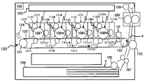
図2は、本実施形態に係る画像形成装置であるカラーレーザープリンタ(以下、単にプリンタという)の概略構成図である。 FIG. 2 is a schematic configuration diagram of a color laser printer (hereinafter simply referred to as a printer) which is an image forming apparatus according to the present embodiment.
図2に示すプリンタは、プリンタ本体100の中央に、プリンタ本体100に対して着脱自在に装着された4つのプロセスカートリッジ102Y,102M,102C,102Bkが設けられている。各プロセスカートリッジ102Y,102M,102C,102Bkは、カラー画像の色分解成分に対応するイエロー(Y)、マゼンタ(M)、シアン(C)、ブラック(Bk)の異なる色の現像剤を収容している以外は同様の構成となっている。そのため、特に色を区別しない場合には、各部材の符号の後にY、M、C、Bkなどの記載は省略する。
The printer shown in FIG. 2 is provided with four process cartridges 102Y, 102M, 102C, and 102Bk that are detachably attached to the printer
各プロセスカートリッジ102は、像担持体である感光体108と、感光体表面を帯電させる帯電装置110と、現像剤を担持する現像ローラ111aを有する現像装置111と、感光体表面をクリーニングするクリーニング装置112などを備える。
Each process cartridge 102 includes a photoconductor 108 that is an image carrier, a
各プロセスカートリッジ102の上方には、感光体108の表面を露光する露光装置103が設けられている。露光装置103は、光源、ポリゴンミラー、f−θレンズ、反射ミラー等を有し、画像データに基づいて各感光体108の表面へレーザー光を照射するようになっている。
Above each process cartridge 102, an
各プロセスカートリッジ102の下方には、転写装置130が配設されている。転写装置130は、中間転写ベルト120と、4つの一次転写ローラ101と、二次転写ローラ123と、二次転写バックアップローラ122と、クリーニングバックアップローラ133と、テンションローラ121と、ベルトクリーニング装置135とを備える。
A
中間転写ベルト120は、無端状のベルトであり、二次転写バックアップローラ122、クリーニングバックアップローラ133及びテンションローラ121によって張架されている。
The
本実施形態では、不図示の駆動装置によって二次転写バックアップローラ122を回転駆動することで、中間転写ベルト120は図の矢印で示す方向に回転するようになっている。また、テンションローラ121の軸方向両端部をばねによって加圧して、中間転写ベルト120に張力を付与している。
In the present embodiment, the secondary
4つの一次転写ローラ101は、それぞれ、各感光体108との間で中間転写ベルト120を挟み込んで一次転写ニップを形成している。また、各一次転写ローラ101には、図示しない単独の高圧電源が接続されており、この高圧電源から+400[V]〜+2500[V]の所定の転写バイアスが印加させることで、転写電界を形成する。
Each of the four primary transfer rollers 101 forms a primary transfer nip by sandwiching the
二次転写ローラ123は、二次転写バックアップローラ122との間で中間転写ベルト120を挟み込んで二次転写ニップを形成している。また、一次転写ローラ101と同様に、二次転写ローラ123にも図示しない高圧電源が接続されており、この高圧電源から所定の転写バイアスが印加されることで、転写電界を形成する。
The
ベルトクリーニング装置135は、中間転写ベルト120に当接するように配設されたクリーニングブレードを有する。
The belt cleaning device 135 has a cleaning blade disposed so as to contact the
一方、プリンタ本体100の下部には、記録媒体としての用紙Pを収容した給紙トレイ104や、給紙トレイ104から用紙Pを搬出する給紙ローラ105等が設けられている。ここで、記録媒体には、普通紙以外に、厚紙、はがき、封筒、薄紙、塗工紙(コート紙やアート紙等)、トレーシングペーパ、OHPシート等が含まれる。また、図示しないが、手差し給紙機構が設けてあってもよい。
On the other hand, a lower portion of the printer
プリンタ本体100内には、用紙Pを給紙トレイ104から二次転写ニップを通過させて装置外へ排出するための搬送路Rが配設されている。搬送路Rにおいて、二次転写ローラ123の位置よりも用紙搬送方向上流側には、二次転写ニップへ用紙Pを搬送する搬送手段としてのレジストローラ対107が配設されている。
In the printer
また、二次転写ローラ123の位置よりも用紙搬送方向下流側には、用紙Pに転写された未定着画像を定着するための定着装置200が配設されている。
Further, a fixing
さらに、定着装置200よりも搬送路Rの用紙搬送方向下流側には、用紙Pを装置外へ排出するための排紙ローラ対109が設けられている。また、プリンタ本体100の上面部には、装置外に排出された用紙Pをストックするための不図示の排紙トレイが設けてある。
Further, a
また、中間転写ベルト120を介してテンションローラ121に対向配置されたトナーマークセンサ(TMセンサ)124は、正反射型センサや拡散型センサによって中間転写ベルト120上のトナー画像の濃度測定や各色のトナー画像の位置測定を行う。そして、トナーマークセンサ124で測定した結果を基にして、所定のタイミングで作像条件を変更し、画像濃度や色合わせの調整が行われる。
Further, a toner mark sensor (TM sensor) 124 disposed opposite to the
以上の構成を備えた画像形成装置の基本動作は次の通りである。
作像動作が開始されると、各プロセスカートリッジ102における各感光体108が図示しない駆動装置によって図中時計回り方向に回転駆動される。各感光体108の表面にはローラ形状の帯電装置110が圧接されており、感光体108の回転に従動して帯電装置110が回転する。そして、図示しない高圧電源によりDC電圧またはDC電圧にAC電圧が重畳されたバイアスを帯電装置110に印加することで、感光体108の表面が帯電装置110によって所定の極性に一様に帯電される。
The basic operation of the image forming apparatus having the above configuration is as follows.
When the image forming operation is started, each photoconductor 108 in each process cartridge 102 is rotationally driven in a clockwise direction in the drawing by a driving device (not shown). A roller-shaped
帯電された各感光体108の表面には、露光装置103から書込光がそれぞれ照射されて、各感光体108の表面に静電潜像が形成される。このとき、各感光体108に露光する画像情報は、所望のフルカラー画像をイエロー、マゼンタ、シアン及びブラックの色情報に分解した単色の画像情報である。なお、この露光工程は、レーザーダイオードを用いたレーザービームスキャナやLEDなどで行われる。
The surface of each charged photoconductor 108 is irradiated with writing light from the
このように各感光体108上に形成された静電潜像に、各現像装置111によって現像ローラ111a上に担持されたトナーが供給されることにより、静電潜像はトナー画像として顕像化(可視像化)される。なお、この現像工程では、図示しない高圧電源から現像装置111の現像ローラ111aに所定の現像バイアスが印加される。 Thus, the electrostatic latent image formed on each photoconductor 108 is visualized as a toner image by supplying the toner carried on the developing roller 111a by each developing device 111. (Visualized). In this developing step, a predetermined developing bias is applied to the developing roller 111a of the developing device 111 from a high voltage power source (not shown).
また、作像動作が開始されると、二次転写バックアップローラ122が図中反時計回り方向に回転駆動し、中間転写ベルト120を図中矢印で示す方向に周回走行させる。そして、各一次転写ローラ101に、トナーの帯電極性と逆極性の定電圧または定電流制御された所定の転写バイアスが印加される。これにより、各一次転写ローラ101と各感光体108との間の一次転写ニップにおいて転写電界が形成される。
When the image forming operation is started, the secondary
その後、各感光体108の回転に伴い、感光体108上の各色のトナー画像が一次転写ニップに達したときに、当該一次転写ニップにおいて形成された転写電界により、各感光体108上のトナー画像が中間転写ベルト120上に順次重ね合わせて転写される。このようにして、中間転写ベルト120の表面にフルカラーのトナー画像が担持される。
Thereafter, when each color toner image on the photoconductor 108 reaches the primary transfer nip as each photoconductor 108 rotates, the toner image on each photoconductor 108 is generated by the transfer electric field formed in the primary transfer nip. Are sequentially superimposed and transferred onto the
また、中間転写ベルト120に転写しきれなかった各感光体108上のトナーは、クリーニング装置112によって除去される。その後、図示しない除電装置によって各感光体108の表面が除電され、表面電位が初期化される。
Further, the toner on each photoconductor 108 that could not be transferred to the
なお、感光体108のまわりにクリーニング装置を設けず、現像装置111で転写残トナーを回収するクリーナレス方式もあり、本実施形態のプリンタでは感光体表面をクリーニングする種々の公知のクリーニング方法を採用できる。 There is also a cleanerless system in which the developing device 111 collects the transfer residual toner without providing a cleaning device around the photoconductor 108, and the printer of this embodiment employs various known cleaning methods for cleaning the surface of the photoconductor. it can.
プリンタ本体100の下部では、給紙ローラ105が回転駆動を開始し、給紙トレイ104から用紙Pが搬送路Rに送り出される。搬送路Rに送り出された用紙Pは、レジストローラ対107によってタイミングを計られて、二次転写ローラ123と二次転写バックアップローラ122との間の二次転写ニップに送られる。このとき、二次転写ローラ123には、中間転写ベルト120上のトナー画像のトナー帯電極性とは逆極性の転写バイアスが印加されており、これにより、二次転写ニップに転写電界が形成されている。
In the lower part of the printer
その後、中間転写ベルト120の回転に伴って、中間転写ベルト120上のトナー画像が二次転写ニップに達したときに、当該二次転写ニップにおいて形成された転写電界によって、中間転写ベルト120上のトナー画像が用紙P上に一括して転写される。
Thereafter, when the toner image on the
また、このとき用紙Pに転写しきれなかった中間転写ベルト120上の残留トナーは、ベルトクリーニング装置135によって除去され、除去されたトナーは図示しない廃トナー収容器へと搬送され回収される。
At this time, the residual toner on the
その後、用紙Pは定着装置200へと搬送され、定着装置200によって熱と圧力により用紙P上のトナー画像が用紙Pに定着される。そして、用紙Pは、排紙ローラ対109によって装置外へ排出され、不図示の排紙トレイ上にストックされる。
Thereafter, the paper P is conveyed to the
このようにして、本実施形態に係るプリンタにおける一連の画像形成プロセスが完了する。 In this way, a series of image forming processes in the printer according to the present embodiment is completed.
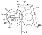
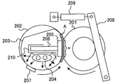
図3は、定着装置200の構成について説明する図である。
定着装置200は、加圧ローラ201、無端状の定着ベルト202、ニップ形成部材205、伝熱部材203、補強部材206、ヒータ204、図示しない第1ステー、第2ステー、シート状部材(シール部材)、温度センサ207、圧接機構等で構成される。
FIG. 3 is a diagram illustrating the configuration of the fixing
The fixing
加圧ローラ201は、直径が20[mm]〜40[mm]程度であって、中空構造の芯金上に弾性層を形成したものである。加圧ローラ201の弾性層は、発泡性シリコーンゴム、シリコーンゴム、フッ素ゴム等の材料で形成されている。なお、弾性層の表面にPFAやPTFE等からなる薄肉の離型層を設けても良い。
The
加圧ローラ201は定着ベルト202に圧接して、加圧ローラ201と定着ベルト202との間に所望の定着ニップNを形成する。
The
加圧ローラ201の軸方向端部には、図示しない駆動ギヤが設置されており、加圧ローラ201は図3中の矢印方向(時計まわり方向)に回転駆動される。また、加圧ローラ201の内部に、ハロゲンヒータ等の熱源を設けて良い。
A driving gear (not shown) is installed at the axial end of the
次に、定着ベルト202は、薄肉で可撓性を有する無端状ベルトであって、図3中の矢印方向(反時計まわり方向)に回転する。
Next, the fixing
定着ベルト202は、ニップ形成部材205との摺接面である内周面側から、基材層、弾性層、離型層が順次積層されており、その全体の厚さが500[μm]以下に設定されている。
The fixing
定着ベルト202の基材層は、層厚が30[μm]〜100[μm]であり、ニッケルやステンレス鋼等の金属材料や、ポリイミド等の樹脂材料で形成されている。
The base material layer of the fixing
定着ベルト202の弾性層は、層厚が100[μm]〜300[μm]であり、シリコーンゴムや発泡性シリコーンゴムやフッ素ゴム等のゴム材料で形成されている。
The elastic layer of the fixing
定着ベルト202に弾性層を設けることで、定着ニップNにおける定着ベルト202表面の微小な凹凸が形成されなくなり、用紙P上のトナー像に均一に熱が伝わりユズ肌画像の発生が抑止される。
By providing an elastic layer on the fixing
定着ベルト202の離型層は、層厚が5[μm]〜50[μm]である。そして、PFA(テトラフルオロエチレン?パーフルオロアルキルビニルエーテル共重合体)、PTFE(ポリテトラフルオロエチレン)、PI(ポリイミド)、PAI(ポリアミドイミド)、PEI(ポリエーテルイミド)、PES(ポリエーテルサルファイド)、PEEK(ポリエーテルケトン)等の材料で形成されている。
The release layer of the fixing
また、定着ベルト202の直径は、15[mm]〜120[mm]になるように設定され、本実施形態では定着ベルト202の直径が30[mm]程度である。
The diameter of the fixing
定着ベルト202の内周面側には、加熱手段としてのヒータ204、ニップ形成部材205、伝熱部材203、補強部材206、図示しない第1ステー、第2ステー、シート状部材等が固設されている。なお、ヒータ204としては、ハロゲンヒータやカーボンヒータを用いることができる。
On the inner peripheral surface side of the fixing
ニップ形成部材205は、定着ベルト202の内周面に摺接するように固設され、定着ベルト202を介して加圧ローラ201に圧接することで、用紙Pが搬送される定着ニップNが形成される。
The
また、伝熱部材203と定着ベルト202とが摺接しても定着ベルト202の摩耗が軽減されるように、定着ベルト202と伝熱部材203との間には、フッ素グリスやシリコーンオイル等の潤滑剤が塗布されている。
Further, lubrication with fluorine grease, silicone oil, or the like is provided between the fixing
伝熱部材203の断面形状は、熱伝達効率や摺動抵抗の観点から、円形の一部を切り落としたような断面形状にしており、これによって定着ベルト202との接触面積を減らし、摺動抵抗を下げることができる。
The cross-sectional shape of the
また、サーミスタ等の温度センサ207から定着ニップN、及び、定着ニップNの搬送方向下流側(図3では定着ニップNの上部)にある伝熱部材203のエッジ部によって、定着ベルト202の張架が実現されている。
Further, the fixing
伝熱部材203は、プリンタ本体100の電源部から電力が供給され不図示の制御部により出力制御されたヒータ204の輻射熱によって加熱される。この輻射熱は反射部材210によって伝熱部材203の一部のみを加熱し、同部位に接触する定着ベルト202が間接的に加熱される。
The
伝熱部材203の材料としては、アルミニウム、鉄、ステンレス鋼等の金属熱伝導体(熱伝導性を有する金属)を用いており、伝熱部材203の肉厚を0.2[mm]以下に設定することで、定着ベルト202の加熱効率を向上することができる。
As a material of the
伝熱部材203は、定着ニップNを除く位置で定着ベルト202の内周面に近接または接触しており、定着ニップNの位置には内部に凹状に形成されるとともに開口部が形成された凹部が設けられている。
The
ここで、常温時における定着ベルト202と伝熱部材203とのギャップG(定着ニップNを除く位置のギャップ)は、0[mm]より大きく2[mm]以下(0mm<G≦2mm)とすることが好ましい。
Here, the gap G (gap at a position excluding the fixing nip N) between the fixing
これにより、伝熱部材203と定着ベルト202とが摺接する面積が大きくなって定着ベルト202の摩耗が加速するのを抑えるとともに、伝熱部材203と定着ベルト202とが離れ過ぎて定着ベルト202の加熱効率が低下するのを抑制できる。
As a result, the area in which the
さらに、伝熱部材203が定着ベルト202に近設されることで、伝熱部材203により、可撓性を有する定着ベルト202の円形姿勢が、ある程度維持されるため、定着ベルト202の変形による劣化や破損を軽減することができる。
In addition, since the
また、伝熱部材203と定着ベルト202との摺動抵抗を低下させるために、伝熱部材203の摺接面を定着ベルト202に対する摩擦係数の低い材料で形成したり、定着ベルト202の内周面にフッ素を含む材料からなる表面層を形成したりしても良い。
Further, in order to reduce the sliding resistance between the
また、ヒータ204からの熱を定着ベルト202に均一に伝達し、且つ、駆動時の定着ベルト202の走行安定性を確保する手段が別途用意されている場合には、伝熱部材203を有さず、定着ベルト202を直接加熱する方式の定着装置を構成することも可能である。その場合は、定着装置全体としての熱容量の内、伝熱部材203の熱容量が排除されるため、より昇温性能や省エネルギー性能に優れた定着装置を構成できる利点がある。
Further, when a means for uniformly transferring the heat from the
なお、ヒータ204の出力制御は、定着ベルト202の表面に対向して配置されたサーミスタ等の温度センサ207による定着ベルト表面温度の検知結果に基づいて行われる。また、このようなヒータ204の出力制御によって、定着ベルト202の温度(定着温度)を所望の温度に設定することができる。
Note that the output control of the
図3に示すように、定着装置200には、定着ベルト202に対して加圧ローラ201を圧接させる圧接機構が設けられている。この圧接機構は、加圧レバー208や加圧スプリング209等で構成されている。
As shown in FIG. 3, the fixing
加圧レバー208は、自身の一端側に設けられた支軸208aを中心として定着装置200の不図示の側板に回転可能に支持されている。加圧レバー208の中央部は、前記側板に形成された長孔に移動可能に保持された、加圧ローラ201の回転軸に当接している。
The
加圧レバー208の他端側には加圧スプリング209の一端が接続されており、加圧スプリング209の他端が定着装置200に設けられた保持板211に接続されている。このような構成により、加圧スプリング209によって引っ張られた加圧レバー208が、支軸208aを中心にして加圧ローラ201の回転軸に向かって回転し、加圧ローラ201が定着ベルト202側に移動することになる。これにより、加圧ローラ201が定着ベルト202を加圧して所望の定着ニップNが形成される。
One end of a
以下、上述のように構成された定着装置200の、通常時の動作について簡単に説明する。
Hereinafter, the normal operation of the fixing
プリンタ本体100の電源スイッチが投入されると、ヒータ204に電力が供給されるとともに、不図示の駆動装置による加圧ローラ201の図3中時計まわり方向の回転駆動が開始される。なお、前記駆動装置には、駆動源である駆動モータや、駆動モータの駆動力を加圧ローラ201に伝達するための駆動ギアなどが設けられており、不図示の制御部によって駆動モータの駆動が制御されている。また、加圧ローラ201が回転することで、加圧ローラ201との間で生じる摩擦力によって定着ベルト202が図3中反時計まわり方向に従動回転する。
When the power switch of the printer
その後、給紙トレイ104から用紙Pが給送されて、二次転写ニップでトナー画像が転写された用紙Pは、不図示のガイド板に案内されながら図3中矢印方向に搬送されて、圧接状態にある定着ベルト202と加圧ローラ201との定着ニップNに進入する。
Thereafter, the paper P is fed from the
そして、ヒータ204からの輻射熱を受けた伝熱部材203によって加熱された定着ベルト202による加熱と、補強部材206によって補強されたニップ形成部材205と加圧ローラ201との押圧力とによって、用紙Pの表面にトナー画像が定着される。
The sheet P is heated by the fixing
その後、用紙Pは定着ニップNから送り出され、排紙ローラ対109により装置外へ排出されて、排紙トレイ上にストックされる。こうして、定着装置200における一連の定着プロセスが完了する。
Thereafter, the paper P is sent out from the fixing nip N, discharged to the outside of the apparatus by the paper
次に、本実施形態に係るプリンタに設けられた定着装置200の特徴部について説明する。
Next, features of the fixing
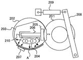
図4は、定着装置200が駆動停止状態、且つ、加熱動作もしていない状態の説明図である。
FIG. 4 is an explanatory diagram of a state in which the
図4に示す、定着装置200が駆動停止状態、且つ、加熱動作も行われていない状態にある初期状態では、定着ベルト202が伝熱部材203によって次のように張架されている。すなわち、定着ベルト回転方向で、温度センサ207と対向する位置から定着ニップNを経て用紙搬送方向下流側の伝熱部材203のエッジ部にかけて、定着ベルト202が伝熱部材203によって張架されている。
In the initial state shown in FIG. 4 in which the
また、定着ベルト202と伝熱部材203との間に、フッ素グリスやシリコーングリス等の潤滑剤が塗布されていることで、定着ベルト202と伝熱部材203とが隙間なく接触している。この潤滑剤は、定着装置200の動作中に、定着ベルト202、伝熱部材203及びニップ形成部材205の間での摩耗を低減する目的で使用されている。
In addition, since a lubricant such as fluorine grease or silicone grease is applied between the fixing
ここで、特許文献2には、定着ベルトと金属パイプ(本実施形態の伝熱部材203に相当)との間に塗布されたグリスを慣らすために、定着ベルトの加熱と回転を行って、グリスを満遍なく行き渡らせて、印刷動作時の駆動トルクを低減することが開示されている。
Here, in Patent Document 2, in order to acclimatize the grease applied between the fixing belt and the metal pipe (corresponding to the
ところが、ウォームアップ動作で、定着装置200が冷えている状態から駆動を開始する際には、低温において粘性の高い潤滑剤が、定着ベルト202、伝熱部材203及びニップ形成部材205の接触面に満遍なく広がっている。そのため、定着ベルト202と伝熱部材203との摺動負荷や、定着ベルト202とニップ形成部材205との摺動負荷が高くなり、定着ベルト202を回転させるための駆動トルクが大きくなってしまう。
However, in the warm-up operation, when the driving is started from the state in which the
なお、潤滑剤の粘性は、高温になると低くなるので、加熱を伴う駆動により、時間とともに徐々に駆動トルクが下がっていく。 Since the viscosity of the lubricant decreases as the temperature rises, the driving torque gradually decreases with time due to driving with heating.
図5は、定着装置200が初期状態からウォームアップ動作を開始するときの説明図である。図6に、通常のウォームアップ動作の制御フローチャートの一例を示す。
FIG. 5 is an explanatory diagram when the fixing
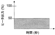
定着装置200が、初期状態からウォームアップ動作を開始する際には(S1)、まず、駆動停止状態でヒータ204による加熱動作が行われる(S2)。加熱時の温度制御は温度センサ207で行い、設定温度は50[℃]とし、且つ、ヒータ204の出力を最大出力値の50[%]に制限することで(図10参照)、過度の加熱と、それによる部材の破損を防止している。
When the fixing
なお、ヒータ204の出力としては、最大出力値の50[%]に限るものではなく、最大出力値の80[%]以下にすれば良い。また、単位時間当たりのヒータ出力の合計が、最大出力値で連続して出力した場合の80[%]以下、好ましくは50[%]以下となるように、最大出力値で断続的に出力して、ヒータ24の出力を制限しても良い(図9参照)。
Note that the output of the
加熱動作により、図5に示した領域Aの伝熱部材203と同領域で接触する定着ベルト202がヒータ204の熱によって間接的に加熱される。そして、定着ベルト回転方向における前記領域Aの範囲内で定着ベルト202の表面に対向した温度センサ207による検知温度が50[℃]以上かを判断する(S3)。そして、温度センサ207による検知温度が50[℃]以上となった時点で(S3でYes)、停止状態での加熱動作を終了する。
By the heating operation, the fixing
停止状態での加熱動作において、設定温度や加熱を終了する条件、ヒータ204の最大出力の制限値は、前記条件に限定されず、定着ベルト202の耐熱温度、ヒータ出力、環境温度などの複合条件により、適宜設定することができる。
In the heating operation in the stop state, the set temperature, the condition for finishing the heating, and the limit value of the maximum output of the
通常のウォームアップ動作では、図5に示した駆動停止状態での加熱動作を終了した後、通常の駆動を開始する(S4)。通常の駆動とは、加熱動作と駆動とを並行して行う状態であり、印刷開始または省エネ待機状態へ移行するまで行われる駆動状態のことである。 In the normal warm-up operation, after the heating operation in the drive stop state shown in FIG. 5 is completed, normal drive is started (S4). The normal drive is a state in which the heating operation and the drive are performed in parallel, and is a drive state that is performed until the start of printing or the shift to the energy saving standby state.
図7は、加熱動作を継続したまま、加圧ローラ201を一定時間だけ駆動させた状態での説明図である。
FIG. 7 is an explanatory diagram in a state where the
図7に示すように、ヒータ204による加熱動作を継続したまま、加圧ローラ201を一定時間だけ駆動させることで、定着ベルト202を従動回転させ、駆動停止状態で加熱した定着ベルト202の領域Aを定着ニップNで停止させる。このとき、加圧ローラ201の回転速度は60[mm/sec]とし、定着ベルト202を1/4回転させるだけの時間、加圧ローラ201を駆動させる。また、ヒータ204の出力としては、最大出力値の80[%]以下にすれば良い。
As shown in FIG. 7, while the heating operation by the
加圧ローラ201の駆動中(定着ベルト202の回転中)も加熱動作を続けることで、ウォームアップ時間を短縮しつつ駆動トルクの低減が実現できるが、加熱動作なしで加圧ローラ201を駆動させ定着ベルト202を回転させても、トルク低減の効果は得られる。
By continuing the heating operation while the
なお、図7を用いて説明した動作の制御を、便宜上、制御Aとする。加圧ローラ201の回転速度や駆動時間については、上記したものに限定されるものではない。すなわち、ヒータ204による伝熱部材203(定着ベルト202)の加熱部位と定着ニップNとの位置関係によって適宜に設定できる。例えば、加圧ローラ201の回転速度としては、加圧ローラ201が回転可能な最大回転速度よりも遅く、駆動時間は定着ベルト202の1回転分以内にすれば良い。
Note that the control of the operation described with reference to FIG. The rotation speed and driving time of the
また、加圧ローラ201の回転速度は、遅くするほど回転開始時の駆動負荷を低減できるため、60[mm/sec]に限定されず、100[mm/sec]以内の範囲で自由に設定できる。
Moreover, since the drive load at the time of a rotation start can be reduced, so that the rotational speed of the
本実施形態の定着装置200では、定着ベルト202が加圧ローラ201の回転に従動回転する構成としているが、これに限るものではない。定着ベルト202を回転駆動させる駆動手段を別途設けて、加圧ローラ201と定着ベルト202とのどちらか、または、両方を駆動させる構成にしても、同様の効果が得られる。
In the
図8は、加熱された定着ベルト202の領域Aを定着ニップNに接する位置で停止させた状態での説明図である。
FIG. 8 is an explanatory diagram in a state where the region A of the
図8に示すように、加熱された定着ベルト202の領域Aは、定着ニップNに接する位置で停止している。この駆動停止状態を3秒間維持することで、定着ニップNで、定着ベルト202から加圧ローラ201とニップ形成部材205それぞれの図中領域Cに熱が伝わる。これにより、定着ニップNに存在する潤滑剤が温められ、潤滑剤の粘性を低くし潤滑剤による摺動負荷を低減することができる。
As shown in FIG. 8, the region A of the
また、駆動停止状態を3秒間維持している間、ヒータ204による加熱動作も並行して行われており、図8に示した領域Bの伝熱部材203と同領域で接触する定着ベルト202がヒータ204の熱によって間接的に加熱される。この際、ヒータ204の出力としては、最大出力値の80[%]以下にすれば良い。
Further, while the driving stop state is maintained for 3 seconds, the heating operation by the
なお、図8を用いて説明した動作の制御を、便宜上、制御Bとする。また、駆動停止状態での停止時間は3秒間に限らず、定着ベルト202やニップ形成部材205や加圧ローラ201などの熱伝導率により適宜設定でき、0.1秒以上であれば良い。
Note that the control of the operation described with reference to FIG. Further, the stop time in the drive stop state is not limited to 3 seconds, and can be set as appropriate according to the thermal conductivity of the fixing
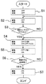
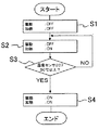
図1に、ウォームアップ動作の制御フローチャートの一例を示す。 FIG. 1 shows an example of a control flowchart of the warm-up operation.
定着装置200が、初期状態からウォームアップ動作を開始する際には(S1)、まず、駆動停止状態でヒータ204による加熱動作が行われる(S2)。加熱時の温度制御は温度センサ207で行い、設定温度は50[℃]とし、且つ、ヒータ204の最大出力を50[%]に制限することで、過度の加熱と、それによる部材の破損を防止している。
When the fixing
加熱動作により、図5に示した領域Aの伝熱部材203と同領域で接触する定着ベルト202がヒータ204の熱によって間接的に加熱される。そして、定着ベルト回転方向における前記領域Aの範囲内で定着ベルト202の表面に対向した温度センサ207による検知温度が50[℃]以上かを判断する(S3)。そして、温度センサ207による検知温度が50[℃]以上となった時点で(S3でYes)、停止状態での加熱動作を終了する。
By the heating operation, the fixing
次に、上記制御Aを実行する。すなわち、ヒータ204による加熱動作を継続したまま、加圧ローラ201を一定時間(ここでは0.4秒)だけ駆動させることで、定着ベルト202を従動回転させ、駆動停止状態で加熱した定着ベルト202の領域Aを定着ニップNで停止させる(S4)。なお、上述したように、ヒータ204による加熱動作なしで加圧ローラ201を駆動させ定着ベルト202を回転させても良い。
Next, the control A is executed. That is, while the heating operation by the
そして、上記制御Bを実行する。すなわち、加熱された定着ベルト202の領域Aが定着ニップNに接する位置で停止した駆動停止状態を3秒間維持するとともに、この間、ヒータ204による加熱動作も並行して行う(S5)。これにより、定着ニップNにおいて、定着ベルト202から加圧ローラ201とニップ形成部材205とに熱が伝わり、定着ニップNに存在する潤滑剤が間接的に温められ、潤滑剤の粘性を低くし潤滑剤による摺動負荷を低減することができる。また、図5に示した定着ベルト202の領域Bの伝熱部材203と同領域で接触する定着ベルト202がヒータ204の熱によって間接的に加熱される。
Then, the control B is executed. In other words, the drive stop state in which the region A of the
その後、制御A及び制御Bそれぞれが4回実行されたかを判断する(S6)。制御A及び制御Bが4回実行されていなければ(S6でNO)、再度、制御Aと制御Bとを繰り返し行う。この際、制御Aでは、制御Bの駆動停止状態で加熱した定着ベルト202の領域Bを、定着ニップNで停止させるような制御を行えば良い。これにより、ウォームアップ時間を短縮することができる。
Thereafter, it is determined whether each of the control A and the control B has been executed four times (S6). If the control A and the control B are not executed four times (NO in S6), the control A and the control B are repeated again. At this time, the control A may be performed so that the region B of the fixing
一方、制御A及び制御Bが4回実行されていれば(S6でYES)、制御Bにおける駆動停止状態での加熱動作を終了した後、通常の駆動を開始し(S7)、ウォームアップ動作制御を終了する。 On the other hand, if the control A and the control B are executed four times (YES in S6), after the heating operation in the drive stop state in the control B is finished, normal driving is started (S7), and the warm-up operation control is performed. Exit.
図1に示すように、前述した制御A及び制御Bは、一連の動作として順次実行され、また、各4回実行される。制御Aと制御Bとを反復して実行することで、定着ニップNの温度が、制御A及び制御Bの実行回数に伴って上昇していき、4回の反復実行によって定着ニップNに存在する潤滑剤を十分に加熱することができる。 As shown in FIG. 1, the above-described control A and control B are sequentially executed as a series of operations, and are executed four times each. By repeatedly executing the control A and the control B, the temperature of the fixing nip N increases with the number of executions of the control A and the control B, and is present in the fixing nip N by four repeated executions. The lubricant can be heated sufficiently.
また、ヒータ204から直接加熱される伝熱部材203の温度も、制御Aと制御Bとの実行回数に伴って上昇し、伝熱部材203の表面に存在する潤滑剤を十分に加熱することができる。
Further, the temperature of the
また、制御Aと制御Bとが、それぞれ4回実行された後に、通常駆動が行われるが、十分に加熱された潤滑剤は粘性が低下しているため、定着装置200の駆動トルクは低減している。
In addition, the normal driving is performed after each of the control A and the control B is executed four times. However, since the viscosity of the sufficiently heated lubricant is reduced, the driving torque of the fixing
なお、制御Aと制御Bとの一連の制御の反復回数については、4回に限定されず、潤滑剤の粘性とその熱特性及び制御Aでの駆動距離により、適宜設定でき、制御Aと制御Bとの一連の制御を少なくとも一回以上行えば良い。 Note that the number of repetitions of the series of control of the control A and the control B is not limited to four, and can be appropriately set according to the viscosity of the lubricant, its thermal characteristics, and the driving distance in the control A. A series of control with B may be performed at least once.
なお、加圧ローラ201の温度を検知する温度検知センサを別途で設けも良い。そして、この温度検知センサによる加圧ローラ201の回転停止状態での温度検知結果が、所定温度以下(例えば50[℃]以下)の場合に、制御Aと制御Bとの一連の制御を少なくとも一回以上行うようにしても良い。この場合でも、潤滑剤の粘性を低くし、定着ニップNに存在する潤滑剤による摺動負荷を低減することができる。
A temperature detection sensor that detects the temperature of the
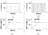
図9を用いて、制御Aと制御Bとで加熱動作を並行して行う場合、ヒータ204の出力を制限することで得られる効果について説明する。
The effect obtained by limiting the output of the
図9(a)はヒータ出力を制限しない場合のグラフであり、図9(b)はヒータ出力を制限した場合を示すグラフである。図9(b)に示すようにヒータ出力を制限することで、図9(a)よりも定着ベルト202の昇温勾配[℃/sec]を小さくすることができる。駆動停止状態で加熱を行う場合、定着ベルト202の一部のみが加熱されてしまい、定着ベルト温度が過度に上昇し、定着ベルト202の耐熱温度を超え、破損に至るおそれがある。
FIG. 9A is a graph when the heater output is not limited, and FIG. 9B is a graph when the heater output is limited. By limiting the heater output as shown in FIG. 9B, the temperature increase gradient [° C./sec] of the fixing
そのため、図9(a)に示すようにヒータ出力を制限せずに加熱動作を行うよりも、図9(b)に示すように単位時間当たりのヒータ出力を制限することで、定着ベルト202の破損を抑制しつつ、駆動停止状態での加熱動作を安全に行うことができる。 Therefore, rather than performing the heating operation without limiting the heater output as shown in FIG. 9A, the heater output per unit time is limited as shown in FIG. It is possible to safely perform the heating operation in the drive stop state while suppressing breakage.
以上に説明したものは一例であり、本発明は、次の態様毎に特有の効果を奏する。
(態様A)
内周面に潤滑剤が塗布された回転可能な無端状の定着ベルト202などの定着ベルトと、定着ベルトの外周面と当接する回転可能な加圧ローラ201などの加圧ローラと、定着ベルトと加圧ローラとの少なくとも一方を回転駆動させる駆動手段と、定着ベルトの内周側に配置され定着ベルトを介して加圧ローラと当接し定着ニップを形成するニップ形成部材205などのニップ形成部材と、定着ベルトの定着ニップ以外の部分を加熱するヒータ204などの加熱手段とを備えた定着装置200などの定着装置において、加熱手段による定着ベルトの加熱を、定着ベルトが停止した状態で所定時間を行うように少なくとも加熱手段を制御する第一制御と、第一制御の実行後に、定着ベルトを所定時間回転させ、定着ベルトの加熱された部分を定着ニップに到達させた後、定着ベルトの回転を停止させるように少なくとも駆動手段を制御する制御Aなどの第二制御と、第二制御の実行後に、定着ベルトの回転停止状態を所定時間維持するように少なくとも駆動手段を制御する制御Bなどの第三制御とを、それぞれ実行可能な制御部などの制御手段を有しており、前記定着ニップに用紙Pなどの記録媒体を送り込む前に定着ベルトを昇温させるウォームアップ動作時で第一制御を実行した後に、第二制御と第三制御との一連の制御を少なくとも一回以上行う。これよれば、上記実施形態について説明したように、ウォームアップ動作時に駆動手段に高負荷がかかり続けて駆動手段が壊れてしまうのを抑制できる。
(態様B)
(態様A)において、上記第二制御で、上記定着ベルトを回転させるときに、上記加熱手段による定着ベルトの加熱を行う。これによれば、上記実施形態について説明したように、ウォームアップ時間を短縮しつつ駆動トルクの低減が実現できる。
(態様C)
(態様A)または(態様B)において、上記第三制御で、上記定着ベルトの回転停止状態を一定時間維持している間、上記加熱手段による定着ベルトの加熱を行う。これによれば、上記実施形態について説明したように、ウォームアップ時間を短縮することができる。
(態様D)
(態様B)または(態様C)において、上記定着ベルトの温度を検知する温度センサ207などの定着ベルト温度検知手段を有しており、上記第二制御と上記第三制御との少なくとも一方で、上記加熱手段による前記定着ベルトの加熱を行う場合、前記定着ベルト温度検知手段の検知結果が、予め設定された定着温度よりも低い温度となるように、上記制御手段が加熱手段を制御する。これによれば、上記実施形態について説明したように、過度の加熱と、それによる部材の破損を抑制できる。
(態様E)
(態様D)において、上記第二制御と上記第三制御との少なくとも一方で、上記加熱手段による上記定着ベルトの加熱を行う場合に、加熱手段の出力を最大出力値の80[%]以下にする。これによれば、上記実施形態について説明したように、過度の加熱と、それによる部材の破損を抑制できる。
(態様F)
(態様A)、(態様B)、(態様C)、(態様D)または(態様E)において、上記駆動手段は上記加圧ローラを回転駆動させるものであり、加圧ローラの回転に従動させて上記定着ベルトを回転させる構成を好適に採用することができる。
(態様G)
(態様F)において、上記第二制御での上記加圧ローラの回転速度は、加圧ローラが回転可能な最大回転速度よりも遅い。これによれば、上記実施形態について説明したように、加圧ローラの回転速度を遅くするほど回転開始時の駆動負荷を低減することができる。
(態様H)
(態様A)、(態様B)、(態様C)、(態様D)、(態様E)、(態様F)または(態様G)において、上記第二制御での上記所定時間としては、上記定着ベルトの一回転分以内に相当する時間とすれば良い。
(態様I)
(態様A)、(態様B)、(態様C)、(態様D)、(態様E)、(態様F)、(態様G)または(態様H)において、上記第三制御での上記所定時間は、0.1秒以上である。これによれば、上記実施形態について説明したように、定着ニップに存在する潤滑剤が温められ、潤滑剤の粘性を低くし、定着ニップに存在する潤滑剤による摺動負荷を低減することができる。
(態様J)
(態様A)、(態様B)、(態様C)、(態様D)、(態様E)、(態様F)、(態様G)、(態様H)または(態様I)において、上記加圧ローラの温度を検知する加圧ローラ温度検知手段を有しており、加圧ローラの回転が停止した状態での前記加圧ローラ温度検知手段による温度検知結果が、所定温度以下の場合に、上記第二制御と上記第三制御との一連の制御を少なくとも一回以上行う。これによれば、上記実施形態について説明したように、潤滑剤の粘性を低くし、定着ニップに存在する潤滑剤による摺動負荷を低減することができる。
(態様K)
感光体108などの像担持体と、像担持体上にトナー像を形成するトナー像形成手段と、トナー像を像担持体上から記録媒体上に転写する転写装置130などの転写手段と、記録媒体上に転写されたトナー像を記録媒体に定着させる定着装置200などの定着手段とを備えた画像形成装置において、前記定着手段として、(態様A)、(態様B)、(態様C)、(態様D)、(態様E)、(態様F)、(態様G)、(態様H)、(態様I)または(態様J)の定着装置を用いる。これによれば、上記実施形態について説明したように、ウォームアップ動作時に駆動手段に高負荷がかかり続けて駆動手段が壊れてしまうのを抑制し、良好な画像形成を行うことができる。
What has been described above is merely an example, and the present invention has a specific effect for each of the following modes.
(Aspect A)
A fixing belt such as a rotatable
(Aspect B)
In (Aspect A), in the second control, when the fixing belt is rotated, the fixing belt is heated by the heating unit. According to this, as described in the above embodiment, it is possible to reduce the drive torque while shortening the warm-up time.
(Aspect C)
In (Aspect A) or (Aspect B), in the third control, the fixing belt is heated by the heating means while the rotation stop state of the fixing belt is maintained for a predetermined time. According to this, as described in the above embodiment, the warm-up time can be shortened.
(Aspect D)
In (Aspect B) or (Aspect C), it has fixing belt temperature detection means such as a
(Aspect E)
In (Aspect D), when the fixing belt is heated by the heating unit in at least one of the second control and the third control, the output of the heating unit is set to 80% or less of the maximum output value. To do. According to this, as explained about the above-mentioned embodiment, excessive heating and the damage of the member by it can be controlled.
(Aspect F)
In (Aspect A), (Aspect B), (Aspect C), (Aspect D) or (Aspect E), the driving means rotates the pressure roller and is driven by the rotation of the pressure roller. Thus, a configuration in which the fixing belt is rotated can be suitably employed.
(Aspect G)
In (Aspect F), the rotation speed of the pressure roller in the second control is slower than the maximum rotation speed at which the pressure roller can rotate. According to this, as described in the above embodiment, the drive load at the start of rotation can be reduced as the rotation speed of the pressure roller is decreased.
(Aspect H)
In (Aspect A), (Aspect B), (Aspect C), (Aspect D), (Aspect E), (Aspect F) or (Aspect G), the predetermined time in the second control is the fixing. A time corresponding to one revolution of the belt may be used.
(Aspect I)
In (Aspect A), (Aspect B), (Aspect C), (Aspect D), (Aspect E), (Aspect F), (Aspect G) or (Aspect H), the predetermined time in the third control Is 0.1 seconds or more. According to this, as described in the above embodiment, the lubricant present in the fixing nip is warmed, the viscosity of the lubricant is lowered, and the sliding load caused by the lubricant present in the fixing nip can be reduced. .
(Aspect J)
In (Aspect A), (Aspect B), (Aspect C), (Aspect D), (Aspect E), (Aspect F), (Aspect G), (Aspect H) or (Aspect I), the pressure roller Pressure roller temperature detection means for detecting the temperature of the pressure roller, and when the temperature detection result by the pressure roller temperature detection means in a state where the rotation of the pressure roller is stopped is equal to or lower than a predetermined temperature, A series of control of the second control and the third control is performed at least once. According to this, as described in the above embodiment, the viscosity of the lubricant can be lowered, and the sliding load caused by the lubricant present in the fixing nip can be reduced.
(Aspect K)
An image carrier such as the photoconductor 108, a toner image forming unit that forms a toner image on the image carrier, a transfer unit such as a
100 プリンタ本体
101 一次転写ローラ
102 プロセスカートリッジ
103 露光装置
104 給紙トレイ
105 給紙ローラ
107 レジストローラ対
108 感光体
109 排紙ローラ対
110 帯電装置
111 現像装置
111a 現像ローラ
112 クリーニング装置
120 中間転写ベルト
121 テンションローラ
122 二次転写バックアップローラ
123 二次転写ローラ
124 トナーマークセンサ
130 転写装置
133 クリーニングバックアップローラ
135 ベルトクリーニング装置
200 定着装置
201 加圧ローラ
202 定着ベルト
203 伝熱部材
204 ヒータ
205 ニップ形成部材
206 補強部材
207 温度センサ
208 加圧レバー
208a 支軸
209 加圧スプリング
210 反射部材
211 保持板
DESCRIPTION OF
Claims (11)
前記定着ベルトの外周面と当接する回転可能な加圧ローラと、
前記定着ベルトと前記加圧ローラとの少なくとも一方を回転駆動させる駆動手段と、
前記定着ベルトの内周側に配置され該定着ベルトを介して前記加圧ローラと当接し定着ニップを形成するニップ形成部材と、
前記定着ベルトの定着ニップ以外の部分を加熱する加熱手段とを備えた定着装置において、
前記加熱手段による前記定着ベルトの加熱を、定着ベルトが停止した状態で所定時間を行うように少なくとも該加熱手段を制御する第一制御と、
前記第一制御の実行後に、前記定着ベルトを所定時間回転させ、該定着ベルトの加熱された部分を前記定着ニップに到達させて、該定着ベルトの回転を停止させるように少なくとも前記駆動手段を制御する前記第二制御と、
前記第二制御の実行後に、前記定着ベルトの回転停止状態を所定時間維持するように少なくとも前記駆動手段を制御する第三制御とを、それぞれ実行可能な制御手段を有しており、
前記定着ニップに記録媒体を送り込む前に前記定着ベルトを昇温させるウォームアップ動作時で前記第一制御を実行した後に、前記第二制御と前記第三制御との一連の制御を少なくとも一回以上行うことを特徴とする定着装置。 A rotatable endless fixing belt having a lubricant applied to the inner peripheral surface;
A rotatable pressure roller in contact with the outer peripheral surface of the fixing belt;
Drive means for rotationally driving at least one of the fixing belt and the pressure roller;
A nip forming member that is disposed on the inner peripheral side of the fixing belt and forms a fixing nip by contacting the pressure roller via the fixing belt;
In a fixing device comprising a heating means for heating a portion other than the fixing nip of the fixing belt,
A first control for controlling at least the heating unit so that the heating of the fixing belt by the heating unit is performed for a predetermined time while the fixing belt is stopped;
After the execution of the first control, the fixing belt is rotated for a predetermined time, the heated portion of the fixing belt reaches the fixing nip, and at least the driving unit is controlled to stop the rotation of the fixing belt. Said second control to
After the execution of the second control, it has control means capable of executing at least a third control for controlling the drive means so as to maintain the rotation stop state of the fixing belt for a predetermined time,
After executing the first control in the warm-up operation for raising the temperature of the fixing belt before feeding the recording medium to the fixing nip, a series of control of the second control and the third control is performed at least once or more A fixing device characterized by performing.
上記第二制御で、上記定着ベルトを回転させるときに、上記加熱手段による該定着ベルトの加熱を行うことを特徴とする定着装置。 The fixing device according to claim 1.
In the second control, when the fixing belt is rotated, the fixing belt is heated by the heating unit.
上記第三制御で、上記定着ベルトの回転停止状態を一定時間維持している間、上記加熱手段による該定着ベルトの加熱を行うことを特徴とする定着装置。 The fixing device according to claim 1 or 2,
In the third control, the fixing device heats the fixing belt by the heating means while maintaining the rotation stop state of the fixing belt for a certain time.
上記定着ベルトの温度を検知する定着ベルト温度検知手段を有しており、
上記第二制御と上記第三制御との少なくとも一方で、上記加熱手段による前記定着ベルトの加熱を行う場合、前記定着ベルト温度検知手段の検知結果が、予め設定された定着温度よりも低い温度となるように、上記制御手段が該加熱手段を制御することを特徴とする定着装置。 The fixing device according to claim 2 or 3,
A fixing belt temperature detecting means for detecting the temperature of the fixing belt;
When at least one of the second control and the third control heats the fixing belt by the heating unit, the detection result of the fixing belt temperature detection unit is a temperature lower than a preset fixing temperature. The fixing device is characterized in that the control means controls the heating means.
上記第二制御と上記第三制御との少なくとも一方で、上記加熱手段による上記定着ベルトの加熱を行う場合に、該加熱手段の出力を最大出力値の80[%]以下にすることを特徴とする定着装置。 The fixing device according to claim 4.
When at least one of the second control and the third control, the fixing belt is heated by the heating means, the output of the heating means is set to 80 [%] or less of the maximum output value. Fixing device to do.
上記駆動手段は上記加圧ローラを回転駆動させるものであり、該加圧ローラの回転に従動させて上記定着ベルトを回転させることを特徴とする定着装置。 The fixing device according to claim 1, 2, 3, 4 or 5.
The fixing device is characterized in that the driving means rotates the pressure roller, and the fixing belt is rotated by the rotation of the pressure roller.
上記第二制御での上記加圧ローラの回転速度は、該加圧ローラが回転可能な最大回転速度よりも遅いことを特徴とする定着装置。 The fixing device according to claim 6.
The fixing device according to claim 2, wherein a rotation speed of the pressure roller in the second control is lower than a maximum rotation speed at which the pressure roller can rotate.
上記第二制御での上記所定時間は、上記定着ベルトの一回転分以内に相当することを特徴とする定着装置。 The fixing device according to claim 1, 2, 3, 4, 5, 6 or 7.
The fixing device according to claim 2, wherein the predetermined time in the second control corresponds to within one rotation of the fixing belt.
上記第三制御での上記所定時間は、0.1秒以上であることを特徴とする定着装置。 The fixing device according to claim 1, 2, 3, 4, 5, 6, 7 or 8.
The fixing device, wherein the predetermined time in the third control is 0.1 second or more.
上記加圧ローラの温度を検知する加圧ローラ温度検知手段を有しており、
該加圧ローラの回転が停止した状態での前記加圧ローラ温度検知手段による温度検知結果が、所定温度以下の場合に、上記第二制御と上記第三制御との一連の制御を少なくとも一回以上行うことを特徴とする定着装置。 The fixing device according to claim 1, 2, 3, 4, 5, 6, 7, 8, or 9.
Having pressure roller temperature detecting means for detecting the temperature of the pressure roller;
When the temperature detection result by the pressure roller temperature detecting means in a state where the rotation of the pressure roller is stopped is equal to or lower than a predetermined temperature, a series of control of the second control and the third control is performed at least once. A fixing device characterized by the above.
像担持体上にトナー像を形成するトナー像形成手段と、
前記トナー像を前記像担持体上から記録媒体上に転写する転写手段と、
前記記録媒体上に転写されたトナー像を該記録媒体に定着させる定着手段とを備えた画像形成装置において、
前記定着手段として、請求項1、2、3、4、5、6、7、8、9または10の定着装置を用いることを特徴とする画像形成装置。 An image carrier;
Toner image forming means for forming a toner image on the image carrier;
Transfer means for transferring the toner image from the image carrier onto a recording medium;
An image forming apparatus comprising: a fixing unit that fixes the toner image transferred onto the recording medium to the recording medium;
An image forming apparatus using the fixing device according to claim 1, 2, 3, 4, 5, 6, 7, 8, 9, or 10 as the fixing unit.
Priority Applications (1)
| Application Number | Priority Date | Filing Date | Title |
|---|---|---|---|
| JP2013053541A JP2014178586A (en) | 2013-03-15 | 2013-03-15 | Fixing device and image forming apparatus |
Applications Claiming Priority (1)
| Application Number | Priority Date | Filing Date | Title |
|---|---|---|---|
| JP2013053541A JP2014178586A (en) | 2013-03-15 | 2013-03-15 | Fixing device and image forming apparatus |
Publications (2)
| Publication Number | Publication Date |
|---|---|
| JP2014178586A true JP2014178586A (en) | 2014-09-25 |
| JP2014178586A5 JP2014178586A5 (en) | 2017-01-12 |
Family
ID=51698565
Family Applications (1)
| Application Number | Title | Priority Date | Filing Date |
|---|---|---|---|
| JP2013053541A Pending JP2014178586A (en) | 2013-03-15 | 2013-03-15 | Fixing device and image forming apparatus |
Country Status (1)
| Country | Link |
|---|---|
| JP (1) | JP2014178586A (en) |
Cited By (2)
| Publication number | Priority date | Publication date | Assignee | Title |
|---|---|---|---|---|
| JP2018146661A (en) * | 2017-03-02 | 2018-09-20 | 株式会社リコー | Heating conveyance device and image forming apparatus |
| JP2018146658A (en) * | 2017-03-02 | 2018-09-20 | 株式会社リコー | Heating conveyance device and image forming apparatus |
Citations (3)
| Publication number | Priority date | Publication date | Assignee | Title |
|---|---|---|---|---|
| JPH10177317A (en) * | 1996-12-16 | 1998-06-30 | Canon Inc | Image forming device |
| JP2010266565A (en) * | 2009-05-13 | 2010-11-25 | Kyocera Mita Corp | Fixing device and image forming apparatus |
| JP2011186275A (en) * | 2010-03-10 | 2011-09-22 | Ricoh Co Ltd | Fixing device and image forming apparatus |
-
2013
- 2013-03-15 JP JP2013053541A patent/JP2014178586A/en active Pending
Patent Citations (3)
| Publication number | Priority date | Publication date | Assignee | Title |
|---|---|---|---|---|
| JPH10177317A (en) * | 1996-12-16 | 1998-06-30 | Canon Inc | Image forming device |
| JP2010266565A (en) * | 2009-05-13 | 2010-11-25 | Kyocera Mita Corp | Fixing device and image forming apparatus |
| JP2011186275A (en) * | 2010-03-10 | 2011-09-22 | Ricoh Co Ltd | Fixing device and image forming apparatus |
Cited By (2)
| Publication number | Priority date | Publication date | Assignee | Title |
|---|---|---|---|---|
| JP2018146661A (en) * | 2017-03-02 | 2018-09-20 | 株式会社リコー | Heating conveyance device and image forming apparatus |
| JP2018146658A (en) * | 2017-03-02 | 2018-09-20 | 株式会社リコー | Heating conveyance device and image forming apparatus |
Similar Documents
| Publication | Publication Date | Title |
|---|---|---|
| JP5850391B2 (en) | Fixing apparatus and image forming apparatus | |
| JP5850326B2 (en) | Fixing apparatus and image forming apparatus | |
| JP2011191348A (en) | Fixing device and image forming apparatus | |
| JP2014199417A (en) | Fixing device and image forming apparatus | |
| JP2014074884A (en) | Fixing device and image forming apparatus | |
| JP6474029B2 (en) | Fixing apparatus and image forming apparatus | |
| JP2013178291A (en) | Fixing device and image forming apparatus | |
| JP2018005047A (en) | Fixing device and image forming apparatus | |
| JP2012118225A (en) | Fixing device and image forming device | |
| US8295750B2 (en) | Fixing apparatus and image forming apparatus equipped therewith | |
| JP4810590B2 (en) | FIXING DEVICE, IMAGE FORMING DEVICE, FIXING DEVICE CONTROL METHOD, CONTROL PROGRAM, AND RECORDING MEDIUM THEREOF | |
| JP2013164453A (en) | Fixing device and image forming device | |
| JP2017003606A (en) | Belt fixing device and image forming apparatus | |
| JP2014178586A (en) | Fixing device and image forming apparatus | |
| JP5011149B2 (en) | Fixing apparatus and image forming apparatus | |
| JP6167670B2 (en) | Fixing apparatus and image forming apparatus | |
| JP6864256B2 (en) | Fixing device, image forming device | |
| JP6848371B2 (en) | Fixing device and image forming device | |
| JP2016109962A (en) | Fixing device and image forming apparatus | |
| JP5190209B2 (en) | Fixing apparatus and image forming apparatus | |
| JP6852370B2 (en) | Fixing device and image forming device | |
| JP6906751B2 (en) | Fixing device, image forming device, and fixing method | |
| JP6812891B2 (en) | Fixing device and image forming device | |
| JP6816484B2 (en) | Fixing device and image forming device | |
| JP6660588B2 (en) | Fixing device and image forming device |
Legal Events
| Date | Code | Title | Description |
|---|---|---|---|
| A621 | Written request for application examination |
Free format text: JAPANESE INTERMEDIATE CODE: A621 Effective date: 20160212 |
|
| A977 | Report on retrieval |
Free format text: JAPANESE INTERMEDIATE CODE: A971007 Effective date: 20161128 |
|
| A521 | Written amendment |
Free format text: JAPANESE INTERMEDIATE CODE: A523 Effective date: 20161129 |
|
| A131 | Notification of reasons for refusal |
Free format text: JAPANESE INTERMEDIATE CODE: A131 Effective date: 20161216 |
|
| A521 | Written amendment |
Free format text: JAPANESE INTERMEDIATE CODE: A523 Effective date: 20170214 |
|
| A131 | Notification of reasons for refusal |
Free format text: JAPANESE INTERMEDIATE CODE: A131 Effective date: 20170512 |
|
| A02 | Decision of refusal |
Free format text: JAPANESE INTERMEDIATE CODE: A02 Effective date: 20171117 |