JP2014170512A - Combination tablet computer and game controller with flexible bridge section - Google Patents
Combination tablet computer and game controller with flexible bridge section Download PDFInfo
- Publication number
- JP2014170512A JP2014170512A JP2013123574A JP2013123574A JP2014170512A JP 2014170512 A JP2014170512 A JP 2014170512A JP 2013123574 A JP2013123574 A JP 2013123574A JP 2013123574 A JP2013123574 A JP 2013123574A JP 2014170512 A JP2014170512 A JP 2014170512A
- Authority
- JP
- Japan
- Prior art keywords
- tablet computer
- input device
- module
- pair
- sides
- Prior art date
- Legal status (The legal status is an assumption and is not a legal conclusion. Google has not performed a legal analysis and makes no representation as to the accuracy of the status listed.)
- Pending
Links
Images


Classifications
-
- A—HUMAN NECESSITIES
- A63—SPORTS; GAMES; AMUSEMENTS
- A63F—CARD, BOARD, OR ROULETTE GAMES; INDOOR GAMES USING SMALL MOVING PLAYING BODIES; VIDEO GAMES; GAMES NOT OTHERWISE PROVIDED FOR
- A63F13/00—Video games, i.e. games using an electronically generated display having two or more dimensions
- A63F13/90—Constructional details or arrangements of video game devices not provided for in groups A63F13/20 or A63F13/25, e.g. housing, wiring, connections or cabinets
- A63F13/92—Video game devices specially adapted to be hand-held while playing
-
- G—PHYSICS
- G06—COMPUTING; CALCULATING OR COUNTING
- G06F—ELECTRIC DIGITAL DATA PROCESSING
- G06F1/00—Details not covered by groups G06F3/00 - G06F13/00 and G06F21/00
- G06F1/16—Constructional details or arrangements
- G06F1/1613—Constructional details or arrangements for portable computers
- G06F1/1632—External expansion units, e.g. docking stations
-
- G—PHYSICS
- G06—COMPUTING; CALCULATING OR COUNTING
- G06F—ELECTRIC DIGITAL DATA PROCESSING
- G06F1/00—Details not covered by groups G06F3/00 - G06F13/00 and G06F21/00
- G06F1/16—Constructional details or arrangements
-
- A—HUMAN NECESSITIES
- A63—SPORTS; GAMES; AMUSEMENTS
- A63F—CARD, BOARD, OR ROULETTE GAMES; INDOOR GAMES USING SMALL MOVING PLAYING BODIES; VIDEO GAMES; GAMES NOT OTHERWISE PROVIDED FOR
- A63F13/00—Video games, i.e. games using an electronically generated display having two or more dimensions
-
- A—HUMAN NECESSITIES
- A63—SPORTS; GAMES; AMUSEMENTS
- A63F—CARD, BOARD, OR ROULETTE GAMES; INDOOR GAMES USING SMALL MOVING PLAYING BODIES; VIDEO GAMES; GAMES NOT OTHERWISE PROVIDED FOR
- A63F13/00—Video games, i.e. games using an electronically generated display having two or more dimensions
- A63F13/20—Input arrangements for video game devices
- A63F13/24—Constructional details thereof, e.g. game controllers with detachable joystick handles
-
- A—HUMAN NECESSITIES
- A63—SPORTS; GAMES; AMUSEMENTS
- A63F—CARD, BOARD, OR ROULETTE GAMES; INDOOR GAMES USING SMALL MOVING PLAYING BODIES; VIDEO GAMES; GAMES NOT OTHERWISE PROVIDED FOR
- A63F13/00—Video games, i.e. games using an electronically generated display having two or more dimensions
- A63F13/90—Constructional details or arrangements of video game devices not provided for in groups A63F13/20 or A63F13/25, e.g. housing, wiring, connections or cabinets
- A63F13/98—Accessories, i.e. detachable arrangements optional for the use of the video game device, e.g. grip supports of game controllers
-
- A—HUMAN NECESSITIES
- A63—SPORTS; GAMES; AMUSEMENTS
- A63F—CARD, BOARD, OR ROULETTE GAMES; INDOOR GAMES USING SMALL MOVING PLAYING BODIES; VIDEO GAMES; GAMES NOT OTHERWISE PROVIDED FOR
- A63F2300/00—Features of games using an electronically generated display having two or more dimensions, e.g. on a television screen, showing representations related to the game
- A63F2300/10—Features of games using an electronically generated display having two or more dimensions, e.g. on a television screen, showing representations related to the game characterized by input arrangements for converting player-generated signals into game device control signals
- A63F2300/1043—Features of games using an electronically generated display having two or more dimensions, e.g. on a television screen, showing representations related to the game characterized by input arrangements for converting player-generated signals into game device control signals being characterized by constructional details
Landscapes
- Engineering & Computer Science (AREA)
- Multimedia (AREA)
- Theoretical Computer Science (AREA)
- Human Computer Interaction (AREA)
- Physics & Mathematics (AREA)
- General Engineering & Computer Science (AREA)
- General Physics & Mathematics (AREA)
- Computer Hardware Design (AREA)
- User Interface Of Digital Computer (AREA)
- Input From Keyboards Or The Like (AREA)
Abstract
Description
本発明は、可撓性のブリッジ部を有するタブレットコンピュータとゲームコントローラとの組み合わせ体に関する。 The present invention relates to a combination of a tablet computer having a flexible bridge portion and a game controller.
この出願は、2012年11月19日に出願された米国特許出願番号第13/681,153号の一部継続出願であり、この米国特許出願番号第13/681,153号は2012年6月12日に出願された米国特許出願番号第13/494,801号の一部継続出願であり、そしてこの米国特許出願番号第13/494,801号は2011年12月20日に出願された米国仮特許出願番号第61/577,709の優先権を主張するものである。 This application is a continuation-in-part of U.S. Patent Application No. 13 / 681,153, filed on November 19, 2012, and this U.S. Patent Application No. 13 / 681,153 is dated June 2012. This is a continuation-in-part of U.S. Patent Application No. 13 / 494,801, filed on the 12th, and U.S. Patent Application No. 13 / 494,801 is filed on Dec. 20, 2011 The priority of provisional patent application number 61 / 577,709 is claimed.
好適な実施形態では、組み合わせ体は、タブレットコンピュータとゲームコントローラとを好ましくは含む。タブレットコンピュータは、複数の側面を提供し、側面のそれぞれは、電子表示画面とタブレットコンピュータの背面との間に配置される。コンピュータゲームコントローラは、タブレットコンピュータの少なくとも2つの対向する側でタブレットコンピュータに隣接して収容する制御モジュールと、一対の制御モジュールをつなぐ構造ブリッジとを提供する。コンピュータゲームコントローラはさらに、入力モジュール開口とカメラとを好ましくは提供する。好ましくは、各入力モジュール開口部は、命令入力装置を固定する。入力モジュール開口部は、タブレットコンピュータの少なくとも2つの対向する側のそれぞれに好ましくは隣接し、カメラは、電子ゲームコントローラ及びタブレットコンピュータのそれぞれと通信し、カメラは静止画像又はビデオ画像のいずれかを選択的に撮影し、構造ブリッジは、一対の制御モジュール間に通信経路を好ましくは提供する。構造ブリッジは、一対の制御モジュールの一方を他方へ固定し、かつタブレットコンピュータの背面の中央領域でタブレットコンピュータの背面と通信する。 In a preferred embodiment, the combination preferably includes a tablet computer and a game controller. The tablet computer provides a plurality of sides, each of which is disposed between the electronic display screen and the back of the tablet computer. The computer game controller provides a control module housed adjacent to the tablet computer on at least two opposite sides of the tablet computer and a structural bridge connecting the pair of control modules. The computer game controller further preferably provides an input module opening and a camera. Preferably, each input module opening fixes a command input device. The input module opening is preferably adjacent to each of at least two opposing sides of the tablet computer, the camera communicates with each of the electronic game controller and the tablet computer, and the camera selects either a still image or a video image The structural bridge preferably provides a communication path between a pair of control modules. The structural bridge secures one of the pair of control modules to the other and communicates with the back of the tablet computer in the central area of the back of the tablet computer.
本発明は一般に、本明細書ではビデオゲーム、コンピュータ及びアプリケーションゲームとも称される電子ゲームの制御とタブレットコンピュータへの情報入力のための、ゲームコントローラと情報入力装置との組み合わせ体に関する。この装置は、好ましくは、タブレットコンピュータと、タブレットコンピュータと通信する電子ゲームと、電子ゲームにより提供された仮想オブジェクトの動きを制御するため及びタブレットコンピュータへ情報を入力するための入力装置とを含む。好適な実施形態では、この入力装置は、タブレットコンピュータの複数の側の対向する側に隣接した、一組の対向する側部構造を含む。入力装置はさらに、好ましくは複数の入力スイッチを含み、この入力スイッチは、タブレットコンピュータの複数の側の少なくとも2つの対向する側のそれぞれと、この一対の側との間に配置されたブリッジ構造に隣接しており、3辺構造を形成する。この第3の構造が、タブレットコンピュータが3辺構造内に完全に収められているとき、タブレットコンピュータが3辺構造から不用意に外れることを軽減する。 The present invention generally relates to a combination of a game controller and an information input device for controlling electronic games, also referred to herein as video games, computers and application games, and for inputting information into a tablet computer. The device preferably includes a tablet computer, an electronic game in communication with the tablet computer, and an input device for controlling movement of virtual objects provided by the electronic game and for inputting information to the tablet computer. In a preferred embodiment, the input device includes a set of opposing side structures adjacent to opposing sides of the plurality of sides of the tablet computer. The input device further preferably includes a plurality of input switches, the input switches in a bridge structure disposed between each of the at least two opposite sides of the plurality of sides of the tablet computer and the pair of sides. Adjacent, forming a three-sided structure. This third structure reduces the inadvertent removal of the tablet computer from the three-sided structure when the tablet computer is completely contained within the three-sided structure.
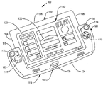
図面を見ると、図1は、本発明のさまざまな実施形態により用いることができる、例示的なゲームコントローラ及び情報入力装置(G&D)100を提供している。例示的なG&D100は、例えば104、106、108、及び126等の複数の側を提供するタブレットコンピュータ102を少なくとも有する。複数の側104、106、及び108のそれぞれは、タブレットコンピュータ102の電子表示画面110とタブレットコンピュータ102の背面112(図2で示す)の間に配置されている。G&D100はさらに、好ましくは入力装置114を含む。
Turning to the drawings, FIG. 1 provides an exemplary game controller and information input device (G & D) 100 that can be used in accordance with various embodiments of the present invention. The exemplary G & D 100 has at least a
好適な実施形態では、入力装置114は、一対の側部構造116及び118、を提供する。一対の側部構造の1つ、例えば116、はタブレットコンピュータ102に隣接し、タブレットコンピュータ102の第1の側、例えばタブレットコンピュータ102の複数の側104、106、108、及び126のうちの104でタブレットコンピュータ102を収容する。一対の側部構造のうちの第2の側部構造、例えば118、はタブレットコンピュータ102に隣接し、タブレットコンピュータ102の第2の側、例えばタブレットコンピュータ102の複数の側104、106、108、及び126のうちの108でタブレットコンピュータ102を収容する。第1及び第2の側、例えばタブレットコンピュータ102の複数の側104、106、108、及び126のうちの104及び108は、タブレットコンピュータ102の複数の側104、106、108、及び126のうちの対向する側である。
In the preferred embodiment, the
好適な実施形態では、入力装置114はさらに、複数の取り外し可能なゲーム制御モジュール120及び122を提供し、取り外し可能なゲーム制御モジュール120及び122は、タブレットコンピュータ102の複数の側104、106、108、及び126のうちの少なくとも2つの対向する側104及び108と、一対の側部構造116及び118の間に配置されてタブレットコンピュータ102の複数の側104、106、108、及び126のうちの第3の側126に隣接したブリッジ構造124と、のそれぞれに隣接する。
In a preferred embodiment, the
好適な実施形態では、取り外し可能なゲーム制御モジュール120及び122は、入力装置114から取り外すことができ、図8の取り外し可能なキーボードモジュール164及び166で置き換えることができる。モジュールの交換を容易にするために、入力装置は好ましくは一対の入力モジュール開口170を提供する。取り外し可能なキーボードモジュールは、集合的にはフル機能のキーボードを形成し、それぞれが補助電子表示画面(ADS)168を提供し、各ADS168は電子表示画面110の機能を少なくとも有する。
In the preferred embodiment, removable
図10に示す別の実施形態では、取り外し可能なキーボードモジュール164及び166は一対のタッチ応答式電子表示画面172及び174であり、電子表示画面110の機能を少なくとも有するこのタッチ応答式電子表示画面のそれぞれは、マウスパッド部176及び178の機能を含み、かつ情報入力のためのキーボード180及び182のキーを選択的に提示する。好ましくは、キーはユーザのタッチに応答する仮想キーである。
In another embodiment shown in FIG. 10, the
図1に戻ると、好ましくは、ブリッジ構造124は一対の側部構造116及び118とともに(図5の)3辺構造128(本明細書では入力装置114のU型構造128とも称される)を形成し、ここにタブレットコンピュータ102が収まり、タブレットコンピュータ102はU型構造128により収容され、U型構造128はタブレットコンピュータが3辺構造128内に完全に収められているとき、タブレットコンピュータがU型構造128から不用意に外れることを軽減するようになっている。
Returning to FIG. 1, preferably, the
図1のG&D100はさらに、好ましくはビデオゲーム130を含む。好ましくは、ビデオゲーム130は電子表示画面110により表示される仮想オブジェクト132を提供し、仮想オブジェクト132は入力装置114からの入力に応答する。仮想オブジェクト132の応答の一例は、入力装置114により提供された所定の信号やキャラクタの出現に応じて、仮想オブジェクト132が動くことや別のコンピュータゲームをロードすることである。なお、図1は複数のスイッチのハウジングを示すのに対し、複数のスイッチの少なくともいくつかは図3の部分切取図に示されている。
The G & D 100 of FIG. 1 further preferably includes a
図2は、タブレットコンピュータ102の背面112が明らかになるように描いたものである。さらに図2には入力装置114が示されており、これが一対のトリガスイッチ136及び138を提供しており、トリガスイッチはそれぞれに対応する側部構造116及び118に支持されている。
FIG. 2 is drawn so that the
図3は、所定数の複数のスイッチ140が互いに協働して入力装置142を形成することを示し、入力装置142は、タブレットコンピュータ102の電子表示画面110に表示される仮想オブジェクトの表示を制御する。好ましくは、入力装置142はジョイスティック142である。図3はさらに、入力装置114が取り外し可能なゲーム制御モジュール120の複数のボタン144及び119を提供することを示しており、これらのボタンで、対応するスイッチ145及び121が作動する。取り外し可能なゲーム制御モジュール120のトリガ138、ジョイスティック142、並びにボタン144及び119の主な機能は、プレイ可能ボディ/オブジェクトの動き/アクションを決定するか、または別の方法で(図1の)ビデオゲーム130又は別のコンピュータゲームにおけるイベントに影響を与えることである。
FIG. 3 illustrates that a predetermined number of
図4は、G&D100がさらに第2のジョイスティック146及び第2のボタン148を含むことを示しており、これらは側部構造116上に、トリガ136に隣接して提供されている。そして一方図5には、入力装置114の中央演算処理装置(CPU)150が示されている。
FIG. 4 shows that the G &
図6は、入力装置114が複数のスイッチ152と相互作用するCPU150を含むことを示し、これらスイッチは好ましくは、(図1の)取り外し可能なゲーム制御モジュール120のスイッチ119、(図1の)取り外し可能なゲーム制御モジュール122のスイッチ117、(図2及び図3の)136、138、142、144、146、及び148を少なくとも含む。図6はさらに、入力装置114が、タブレットコンピュータ102と入力装置114との間に通信リンクを提供する通信プロトコル154を含むことを示す。好適な実施形態では、ユニバーサルシリアルバス(USB)通信プロトコルが使用される。しかし、当業者であれば分かるように、通信プロトコル154はUSBプロトコルに限定されるものではない。
FIG. 6 shows that the
図6はさらに、タブレットコンピュータ102が好ましくはCPU156を少なくとも含み、CPU156は、電子表示画面110と、ビデオゲーム130と、タブレットコンピュータ102と入力装置114との間の相互作用を促進するデバイスドライバ158と、タブレットコンピュータ102と入力装置114との間に通信リンクを提供する通信プロトコル160と、相互作用することを示す。好適な実施形態では、ユニバーサルシリアルバス(USB)通信プロトコルが使用される。しかし、当業者であれば分かるように、通信プロトコル160はUSBプロトコルに限定されるものではない。
FIG. 6 further illustrates that the
図7は、例示的なゲームコントローラ162の代替的な実施形態を示し、ここではデバイスドライバ158及びビデオゲーム130は入力装置114に配置される。
図8は、好適な実施形態では、G&D100は、タブレットコンピュータ102の第1の側にある第1のカメラ184、タブレットコンピュータ102の背面側にある第2のカメラ186(図9に示す)、入力装置114の第1の側にある第3のカメラ188、及び入力装置114の背面側にある第4のカメラ190(図9に示す)を含むことを示す。
FIG. 7 shows an alternative embodiment of an
FIG. 8 illustrates that, in a preferred embodiment, the G &
好適な実施形態では、4つのカメラそれぞれが選択的に独立して機能すること、又は互いに連携して用いられることが可能であり、4つのカメラ184、186、188、及び190はそれぞれ、静止画像及びビデオ画像の撮影において完全に機能する。加えて、そして好ましくは、第1及び第2のカメラ184及び186は、タブレットコンピュータ102が入力装置114から分離されたときであっても完全に動作し、そして第3及び第4のカメラ188及び190は、入力装置114がタブレットコンピュータ102から分離されたときであっても完全に機能する。
In a preferred embodiment, each of the four cameras can selectively function independently or can be used in conjunction with each other, and each of the four
好適な実施形態では、タブレットコンピュータ102が入力装置114に収まっているとき、第1及び第2のカメラ184及び186は、タブレットコンピュータ102又は入力装置114のいずれからの入力に対しても、第1及び第2のカメラ184及び186の制御のためにどちらの装置が選択されているかによって、単独又は同時のいずれかで応答する。さらに、好適な実施形態では、タブレットコンピュータ102及び入力装置114のそれぞれがブルートゥースプロトコルスタック通信の特徴を持つように構成され、これによりユーザは、タブレットコンピュータ102が入力装置114から分離されているときであっても、タブレットコンピュータ102の第1及び第2のカメラ184及び186を入力装置114で操作することが可能になる。同じように、タブレットコンピュータ102及び入力装置114はブルートゥースプロトコルスタック通信の特徴を持つように構成されているとき、ユーザは、入力装置114の第3及び第4のカメラ188及び190を、タブレットコンピュータ102を用いて操作することができる。換言すれば、好適な実施形態では、4つのカメラ184、186、188、及び190はそれぞれ、タブレットコンピュータ102が入力装置114内に収まっているか否かに関わらず、単独又はまとめて、選択的に動作させることができる。
In a preferred embodiment, when the
図9は、好適な実施形態では、入力装置114は補助電源192と補助データストレージ装置194とを含み、補助データストレージ装置194はキャッシュ部分196を含むことを示す。好ましくは、補助電源192はリチウムイオン電池であり、タブレットコンピュータ102の電源が抜かれているとき入力装置114及びタブレットコンピュータ102へ電力を供給し、また補助データストレージ装置194はソリッドステートハードドライブであることが好ましい。
FIG. 9 illustrates that in a preferred embodiment,
好適な実施形態では、キャッシュ196は、カメラ184、186、188、及び190からの同期入力をバッファできる大きさにされて、補助データストレージ装置194が静止画像又はビデオ画像の格納及び取り出しを行ってシームレスに表示できるようにし、このシームレスな表示には、カメラ184、186、188、及び190のそれぞれにより記録されたビデオ画像を同時に出力することを含む。
In the preferred embodiment, the
カメラ184、186、188、及び190の使用の非制限的で例示的なアプリケーションでは、第1のカメラ184は情報プレゼンタに向けられ、第2のカメラ186はプレゼンテーションに参加している聴衆の一部に向けられる。第3のカメラ188は、プレゼンタが聴衆へ情報を提示するために用いているスクリーンに向けられ、第4のカメラは、聴衆の別の一部へ向けられる。記録されたプレゼンテーションを同時に再生することにより、聴衆の情報に対する反応及び提示されている情報の順序を分析してプレゼンテーションの改善に役立てることができる。
In a non-limiting exemplary application of the use of
図11はビデオゲームコントローラ200の代替的な実施形態を示し、ビデオゲームコントローラ200は、組み込まれたトランザクションカード入力特徴202を提供する。好ましくは、組み込まれたトランザクションカード入力特徴202は、トランザクションカードスロット204及びトランザクションカードリーダ206を含む。好適な実施形態では、トランザクションカードリーダ206は磁気ストリップリーダであるが、当業者であれば分かるように、トランザクションカードリーダは、他に光学式文字認識リーダ、バーコードリーダ、物体認識リーダ、又はパターン認識リーダであってもよい。
FIG. 11 shows an alternative embodiment of a
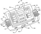
図12は、好適な実施形態では、組み込まれたポイントオブセール装置210を有する、タブレットコンピュータと電子ゲームコントローラとの組み合わせ体は、複数の側214を有するタブレットコンピュータ212であって、複数の側214のそれぞれがタブレットコンピュータの電子表示画面216とタブレットコンピュータの背面218との間に配置された、タブレットコンピュータ212と、タブレットコンピュータ212と電子通信する入力装置220とを、好ましくは含むことを示す。入力装置220は、好ましくは、タブレットコンピュータ212の複数の側214の少なくとも2つの対向する側でタブレットコンピュータに隣接して収容する側部構造222を提供する。入力装置220はさらに、入力モジュール開口224を好ましくは提供し、各入力モジュール開口224は、ゲーム制御モジュール、例えば図1の102及び122、又は取り外し可能なキーボードモジュール、例えば226及び228、のいずれかを選択的に受け入れる。好ましくは、入力モジュール開口224は、タブレットコンピュータ212の複数の側214の少なくとも2つの対向する側のそれぞれに隣接する。
FIG. 12 illustrates that in a preferred embodiment, the combination tablet computer and electronic game controller with an integrated point-of-
図12はさらに、好適な実施形態では、組み込まれたポイントオブセール装置210を有する、タブレットコンピュータと電子ゲームコントローラとの組み合わせ体が、入力装置220及びタブレットコンピュータ212のそれぞれと通信するカメラ230を好ましくは含むことを示す。カメラ230は、静止画像又はビデオ画像のいずれかを選択的に撮影し、入力装置220は、トランザクションカード234と相互作用する組み込まれたトランザクションカード入力特徴232をさらに提供し、また、入力装置は好ましくは電子ゲームコントローラ220である。好ましくは、カメラ230はユーザが電子表示画面216に顔を向けているときにユーザの方を向いているレンズを有する第1のカメラであり、第1のカメラ184のものとは反対の方向を向いたレンズを有する第2のカメラ、例えば(図9の)186又は190、を少なくとも含む。
FIG. 12 further illustrates that, in a preferred embodiment, a combination tablet computer and electronic game controller having an integrated point-of-
図12は、タブレットコンピュータ212の電子表示画面216に表示されたアプリケーション236も示している。好ましくは、タブレットコンピュータ212の電子表示画面216に表示されたアプリケーション236は、ポイントオブセールトランザクションのコンピュータアプリケーションであり、このアプリケーションは電子ゲームコントローラ220及びタブレットコンピュータ212と相互作用をする。
FIG. 12 also shows an
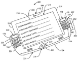
図13は、タブレットコンピュータと電子ゲーム制御体240との組み合わせ体(本明細書では装置240とも称される)の代替的な実施形態を示す。タブレットコンピュータ242は、複数の側244を好ましくは提供し、複数の側のそれぞれはタブレットコンピュータ242の電子表示画面246とタブレットコンピュータ242の背面248との間に配置される。
FIG. 13 illustrates an alternative embodiment of a combination tablet computer and electronic game controller 240 (also referred to herein as device 240).
好ましくは、電子ゲームコントローラ250(本明細書では入力装置250とも称される)は、タブレットコンピュータ242と電子通信している。好ましくは、入力装置250は一対の制御モジュール252を提供する。一対の制御モジュール252は、タブレットコンピュータ242の複数の側244の少なくとも2つの対向する側でタブレットコンピュータ242に隣接しタブレットコンピュータ24を収容する。一対の制御モジュール252は、好ましくは入力モジュール開口254を提供し、各入力モジュール開口254は命令入力装置256を固定する。好ましくは、入力モジュール開口254は、タブレットコンピュータ242の複数の側244の少なくとも2つの対向する側のそれぞれに隣接する。
Preferably, electronic game controller 250 (also referred to herein as input device 250) is in electronic communication with
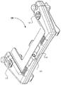
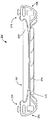
図14はタブレットコンピュータ242の背面248を示し、タブレットコンピュータ242は部分的に入力装置250内に位置している。図14はさらに構造ブリッジ258を示し、構造ブリッジ258は一対の制御モジュール252の一方を他方に固定し、かつタブレットコンピュータ242の背面248の中央領域260でタブレットコンピュータ242の背面248と通信する。
FIG. 14 shows the
図14はさらに、一対の制御モジュール252が固定用突起(confinement boss)262を提供し、この固定用突起262が締め付け戻り止め(fastening detent)264を提供することを示す。締め付け戻り止め264は保持部材266と相互作用して、構造ブリッジ258を一対の制御モジュール252に固定する。好適な実施形態では、保持部材266はキャッチ268に対応しており、これは、ばねで動くキャッチ268であることが好ましく、保持部材268は、ばねで留められた保持部材268であるのが好ましい。またさらに図14は、好適な実施形態では、構造ブリッジ258が一対の制御モジュール252の間に信号を伝える通信リンク270を提供することを示す。
FIG. 14 further shows that a pair of
引き続き図14を見ると、好適な実施形態では、通信リンク270は、一対の制御モジュール252の間に信号を伝えるために、通信モジュール272を提供し、そして代替的にはシグナル経路274を提供する。好適な実施形態では、通信モジュール272は、2.4GHzの周波数レンジで動作するワイヤレス通信モジュール272である。別の好適な実施形態では、ワイヤレス通信モジュール272はパーソナルエリアネットワークである。当業者であれば分かるように、パーソナルエリアネットワーク(PAN)は、電話や携帯情報端末を含むコンピュータ化された装置間の通信のために使用されるコンピュータネットワークである。PANは、個人用装置自体の間の通信(個人間通信)のために用いることもできるし、又は上位レベルのネットワーク及びインターネット(アップリンク)へ接続するために用いることができる。ワイヤレスパーソナルエリアネットワーク(WPAN)はPANがワイヤレスネットワーク技術に持ち込まれたものであり、ワイヤレスネットワーク技術は例えば、IrDA、ブルートゥース(Bluetooth(登録商標))、WirelessUSB、Z−Wave、ZigBee、又は人体通信網(Body Area Network)までも含む。WPANの及ぶ範囲は数センチから数メートルまで様々である。PANは、例えばUSBやFireWireといった有線のコンピュータバスにも持ち込まれる。
Continuing with FIG. 14, in a preferred embodiment, the
シグナル経路274を通信リンクとして使用する実施形態では、シグナル経路274は、金属導体、光ファイバ導体、導体ポリマ、又はフレックス回路の導体層の形であってよい。当業者であればさらに、(図14の)構造ブリッジ258又は(図15の)276は硬質ポリマ等の硬質材料又は可撓性ポリマ等の可撓性材料のいずれで形成してもよいことが分かるであろう。好適な実施形態では、可撓性材料が選択され、かつシグナル経路274が有線の経路であるとき、図15に示すように、シグナル経路274は構造ブリッジ276の外側に結合されてもよい。
In embodiments where the
図15はさらに、好適な実施形態では、命令入力装置256は電子ゲーム制御体モジュール278(取り外し可能なもの又は固定されたもののいずれか)、又はキーボードモジュール280(図13の、取り外し可能なもの又は固定されたもののいずれか)であり得ることを示す。
FIG. 15 further illustrates that in a preferred embodiment, the
前述の記載において本発明のさまざまな実施形態の数多くの特徴及び構成を、本発明のさまざまな実施形態の構造及び機能の詳細とともに述べたが、この詳細な説明は単に例示であって詳細については変更が可能であり、特に構造関連事項及び部品の配置においての変更は本発明の原理の範囲内で行うことができ、添付の特許請求の範囲の表現に用いられた用語の広義の一般的な意味により示される最大限の範囲まで変更が可能である。例えば、本発明の精神及び要旨から逸脱しない範囲で、特定の要素が特定のタブレットコンピュータによって異なっていてもよい。 Although numerous features and configurations of various embodiments of the invention have been described in the foregoing description, together with details of the structure and function of the various embodiments of the invention, this detailed description is merely exemplary and not in detail Changes, particularly in structural matters and arrangements of components, can be made within the scope of the principles of the present invention, and the broad general terms of the terms used in the claims appended hereto Changes can be made to the maximum extent indicated by the meaning. For example, specific elements may vary depending on a specific tablet computer without departing from the spirit and gist of the present invention.
Claims (20)
複数の側を提供するタブレットコンピュータであって、前記複数の側のそれぞれは前記タブレットコンピュータの電子表示画面と前記タブレットコンピュータの背面との間に配置された、タブレットコンピュータと、
前記タブレットコンピュータと電子通信している入力装置であって、一対の制御モジュールを提供し、前記一対の制御モジュールは前記タブレットコンピュータに隣接し、前記タブレットコンピュータの前記複数の側の少なくとも2つの対向する側で前記タブレットコンピュータを収容し、前記一対の制御モジュールは入力モジュール開口を提供し、各入力モジュール開口は命令入力装置を固定し、前記入力モジュール開口は、前記タブレットコンピュータの前記複数の側の前記少なくとも2つの対向する側のそれぞれに隣接する、入力装置と、
前記一対の制御モジュールの一方を他方に固定し、かつ前記タブレットコンピュータの前記背面の中央領域で前記タブレットコンピュータの前記背面と通信する構造ブリッジであって、前記入力装置は電子ゲームコントローラである、構造ブリッジと
を備えた装置。 A device,
A tablet computer providing a plurality of sides, each of the plurality of sides being disposed between an electronic display screen of the tablet computer and the back of the tablet computer;
An input device in electronic communication with the tablet computer, comprising a pair of control modules, the pair of control modules adjacent to the tablet computer and facing at least two of the plurality of sides of the tablet computer Housing the tablet computer on the side, the pair of control modules providing input module openings, each input module opening securing a command input device, and the input module openings are located on the plurality of sides of the tablet computer. An input device adjacent to each of the at least two opposing sides;
A structural bridge that fixes one of the pair of control modules to the other and communicates with the back surface of the tablet computer in a central region of the back surface of the tablet computer, wherein the input device is an electronic game controller A device with a bridge.
前記一対の制御モジュールの間に信号を伝える通信リンクと、
前記一対の制御モジュールの一方を他方に固定するために前記固定用突起と協働する締め付け機構と、
を備えた、装置。 The apparatus of claim 1, wherein the pair of control modules provide a locking projection, and the structural bridge comprises:
A communication link for transmitting signals between the pair of control modules;
A clamping mechanism that cooperates with the fixing protrusion to fix one of the pair of control modules to the other;
Equipped with the device.
Applications Claiming Priority (2)
| Application Number | Priority Date | Filing Date | Title |
|---|---|---|---|
| US13/779,987 | 2013-02-28 | ||
| US13/779,987 US8529357B2 (en) | 2011-12-20 | 2013-02-28 | Combination tablet computer and game controller with flexible bridge section |
Publications (1)
| Publication Number | Publication Date |
|---|---|
| JP2014170512A true JP2014170512A (en) | 2014-09-18 |
Family
ID=48874882
Family Applications (1)
| Application Number | Title | Priority Date | Filing Date |
|---|---|---|---|
| JP2013123574A Pending JP2014170512A (en) | 2013-02-28 | 2013-06-12 | Combination tablet computer and game controller with flexible bridge section |
Country Status (12)
| Country | Link |
|---|---|
| EP (1) | EP2772825A3 (en) |
| JP (1) | JP2014170512A (en) |
| CN (1) | CN104014129B (en) |
| AU (2) | AU2013203031A1 (en) |
| BR (1) | BR102013007824A2 (en) |
| CA (1) | CA2815982A1 (en) |
| HK (1) | HK1201488A1 (en) |
| MX (1) | MX2013007162A (en) |
| NZ (1) | NZ609051A (en) |
| RU (1) | RU2641231C2 (en) |
| TW (1) | TWI631976B (en) |
| WO (1) | WO2014133558A1 (en) |
Cited By (2)
| Publication number | Priority date | Publication date | Assignee | Title |
|---|---|---|---|---|
| JP2018511352A (en) * | 2015-02-02 | 2018-04-26 | ウィキパッド,インコーポレーテッド | Combination of computing device and game controller with flexible bridge section |
| JP2018152042A (en) * | 2017-03-13 | 2018-09-27 | ウィキパッド,インコーポレーテッド | Game controller with flexible bridge supporting touch screen |
Families Citing this family (14)
| Publication number | Priority date | Publication date | Assignee | Title |
|---|---|---|---|---|
| US9841786B2 (en) | 2011-12-20 | 2017-12-12 | Wikipad, Inc. | Combination computing device and game controller with flexible bridge and supporting a transaction apparatus |
| US9764231B2 (en) | 2011-12-20 | 2017-09-19 | Wikipad, Inc. | Combination computing device and game controller with touch screen input |
| US9592452B2 (en) | 2011-12-20 | 2017-03-14 | Wikipad, Inc. | Combination computing device and game controller with flexible bridge section |
| US9841824B2 (en) | 2011-12-20 | 2017-12-12 | Wikipad, Inc. | Combination computing device and game controller with flexible bridge and supporting a keyboard module |
| US9757647B2 (en) | 2015-06-12 | 2017-09-12 | Nintendo Co., Ltd. | Game controller |
| JP6612183B2 (en) | 2015-06-12 | 2019-11-27 | 任天堂株式会社 | Game controller |
| WO2017039636A1 (en) * | 2015-08-31 | 2017-03-09 | Wikipad, Inc. | Combination computing device and game controller with flexible bridge section |
| WO2017039637A1 (en) * | 2015-08-31 | 2017-03-09 | Wikipad, Inc. | Combination computing device and game controller with flexible bridge section |
| EP3305382B1 (en) | 2016-10-06 | 2019-02-27 | Nintendo Co., Ltd. | Attachment |
| JP6153238B1 (en) | 2016-10-06 | 2017-06-28 | 任天堂株式会社 | Attachment and operation system |
| JP6931285B2 (en) | 2017-01-11 | 2021-09-01 | 任天堂株式会社 | Attachment for game controller |
| DE202017102713U1 (en) * | 2017-05-08 | 2017-06-06 | Technische Universität Chemnitz | Holder for holding and operating tablet PC |
| CN108031111A (en) * | 2017-12-29 | 2018-05-15 | 安徽科创智慧知识产权服务有限公司 | Have wireless and wired connection handle system concurrently |
| US10940385B2 (en) * | 2019-07-30 | 2021-03-09 | Sony Interactive Entertainment Inc. | Controller add-on device with customizable presets |
Citations (4)
| Publication number | Priority date | Publication date | Assignee | Title |
|---|---|---|---|---|
| JP2002018131A (en) * | 2000-07-07 | 2002-01-22 | Konami Co Ltd | Controller for game machine |
| JP2003018275A (en) * | 2001-07-04 | 2003-01-17 | Hori Co Ltd | Extended controller to be used in combination with mobile telephone set |
| JP2003093742A (en) * | 2001-06-20 | 2003-04-02 | Alphagrip Inc | Hand grippable combined keyboard and game controller system |
| US20100081505A1 (en) * | 2008-09-30 | 2010-04-01 | Apple Inc. | Accessory for playing games with a portable electronic device |
Family Cites Families (6)
| Publication number | Priority date | Publication date | Assignee | Title |
|---|---|---|---|---|
| WO2004075428A2 (en) * | 2003-02-19 | 2004-09-02 | Flextronics Sales & Marketing (A-P) Ltd. | Personal entertainment device (ped) with double-opening flap |
| US20060205517A1 (en) * | 2005-03-08 | 2006-09-14 | Malabuyo Paolo V | Systems and methods for providing a system level user interface in a multimedia console |
| EP2018030A1 (en) * | 2007-07-18 | 2009-01-21 | Blue Bee Limited | A docking station and a kit for a personal electronic device |
| US8634873B2 (en) * | 2010-03-17 | 2014-01-21 | Microsoft Corporation | Mobile communication device having multiple, interchangeable second devices |
| CN201851852U (en) * | 2010-10-27 | 2011-06-01 | 苏州达方电子有限公司 | Supporting mechanism and portable electronic module thereof |
| CN202472494U (en) * | 2012-01-17 | 2012-10-03 | 韩莹光 | Tablet computer with built-in gamepad |
-
2013
- 2013-03-14 WO PCT/US2013/031322 patent/WO2014133558A1/en active Application Filing
- 2013-04-01 BR BR102013007824A patent/BR102013007824A2/en not_active IP Right Cessation
- 2013-04-08 AU AU2013203031A patent/AU2013203031A1/en not_active Abandoned
- 2013-04-08 RU RU2013115717A patent/RU2641231C2/en not_active IP Right Cessation
- 2013-04-10 TW TW102112612A patent/TWI631976B/en not_active IP Right Cessation
- 2013-04-11 NZ NZ609051A patent/NZ609051A/en not_active IP Right Cessation
- 2013-05-16 CA CA2815982A patent/CA2815982A1/en not_active Abandoned
- 2013-05-21 CN CN201310189183.1A patent/CN104014129B/en not_active Expired - Fee Related
- 2013-06-12 JP JP2013123574A patent/JP2014170512A/en active Pending
- 2013-06-20 MX MX2013007162A patent/MX2013007162A/en unknown
- 2013-07-25 EP EP13178079.3A patent/EP2772825A3/en not_active Withdrawn
-
2015
- 2015-03-02 HK HK15102048.1A patent/HK1201488A1/en not_active IP Right Cessation
-
2016
- 2016-05-11 AU AU2016203066A patent/AU2016203066A1/en not_active Abandoned
Patent Citations (4)
| Publication number | Priority date | Publication date | Assignee | Title |
|---|---|---|---|---|
| JP2002018131A (en) * | 2000-07-07 | 2002-01-22 | Konami Co Ltd | Controller for game machine |
| JP2003093742A (en) * | 2001-06-20 | 2003-04-02 | Alphagrip Inc | Hand grippable combined keyboard and game controller system |
| JP2003018275A (en) * | 2001-07-04 | 2003-01-17 | Hori Co Ltd | Extended controller to be used in combination with mobile telephone set |
| US20100081505A1 (en) * | 2008-09-30 | 2010-04-01 | Apple Inc. | Accessory for playing games with a portable electronic device |
Cited By (3)
| Publication number | Priority date | Publication date | Assignee | Title |
|---|---|---|---|---|
| JP2018511352A (en) * | 2015-02-02 | 2018-04-26 | ウィキパッド,インコーポレーテッド | Combination of computing device and game controller with flexible bridge section |
| JP2019048085A (en) * | 2015-02-02 | 2019-03-28 | ウィキパッド,インコーポレーテッド | Combination of computing device and game controller provided with flexible bridge section |
| JP2018152042A (en) * | 2017-03-13 | 2018-09-27 | ウィキパッド,インコーポレーテッド | Game controller with flexible bridge supporting touch screen |
Also Published As
| Publication number | Publication date |
|---|---|
| CN104014129A (en) | 2014-09-03 |
| EP2772825A2 (en) | 2014-09-03 |
| HK1201488A1 (en) | 2015-09-04 |
| MX2013007162A (en) | 2014-09-01 |
| WO2014133558A1 (en) | 2014-09-04 |
| AU2016203066A1 (en) | 2016-06-02 |
| CA2815982A1 (en) | 2014-08-28 |
| AU2013203031A1 (en) | 2014-09-11 |
| EP2772825A3 (en) | 2014-11-05 |
| NZ609051A (en) | 2014-11-28 |
| TW201433340A (en) | 2014-09-01 |
| TWI631976B (en) | 2018-08-11 |
| BR102013007824A2 (en) | 2016-08-02 |
| CN104014129B (en) | 2016-10-26 |
| RU2641231C2 (en) | 2018-01-16 |
| RU2013115717A (en) | 2014-10-20 |
Similar Documents
| Publication | Publication Date | Title |
|---|---|---|
| JP2014170512A (en) | Combination tablet computer and game controller with flexible bridge section | |
| US8529357B2 (en) | Combination tablet computer and game controller with flexible bridge section | |
| US9126119B2 (en) | Combination computing device and game controller with flexible bridge section | |
| US8788348B2 (en) | Combination game controller and point of sale input device | |
| US8944912B2 (en) | Combination game controller and information input device for a tablet computer | |
| JP6730400B2 (en) | Combination of computing device and game controller with flexible bridge section | |
| NO20150673A1 (en) | Combination game controller and information input device | |
| JP2014170513A (en) | Combination game controller and point of sale input device |
Legal Events
| Date | Code | Title | Description |
|---|---|---|---|
| A621 | Written request for application examination |
Free format text: JAPANESE INTERMEDIATE CODE: A621 Effective date: 20160608 |
|
| A131 | Notification of reasons for refusal |
Free format text: JAPANESE INTERMEDIATE CODE: A131 Effective date: 20170321 |
|
| A977 | Report on retrieval |
Free format text: JAPANESE INTERMEDIATE CODE: A971007 Effective date: 20170322 |
|
| A601 | Written request for extension of time |
Free format text: JAPANESE INTERMEDIATE CODE: A601 Effective date: 20170616 |
|
| A601 | Written request for extension of time |
Free format text: JAPANESE INTERMEDIATE CODE: A601 Effective date: 20170817 |
|
| A521 | Request for written amendment filed |
Free format text: JAPANESE INTERMEDIATE CODE: A523 Effective date: 20170920 |
|
| A131 | Notification of reasons for refusal |
Free format text: JAPANESE INTERMEDIATE CODE: A131 Effective date: 20171011 |
|
| A02 | Decision of refusal |
Free format text: JAPANESE INTERMEDIATE CODE: A02 Effective date: 20180507 |