JP2014167224A - Toilet apparatus - Google Patents
Toilet apparatus Download PDFInfo
- Publication number
- JP2014167224A JP2014167224A JP2013039115A JP2013039115A JP2014167224A JP 2014167224 A JP2014167224 A JP 2014167224A JP 2013039115 A JP2013039115 A JP 2013039115A JP 2013039115 A JP2013039115 A JP 2013039115A JP 2014167224 A JP2014167224 A JP 2014167224A
- Authority
- JP
- Japan
- Prior art keywords
- toilet
- light source
- source device
- ultraviolet rays
- wavelength
- Prior art date
- Legal status (The legal status is an assumption and is not a legal conclusion. Google has not performed a legal analysis and makes no representation as to the accuracy of the status listed.)
- Pending
Links
- 238000001514 detection method Methods 0.000 claims abstract description 49
- 230000001699 photocatalysis Effects 0.000 claims abstract description 20
- 230000001678 irradiating effect Effects 0.000 claims description 15
- 230000005284 excitation Effects 0.000 abstract description 9
- 230000001629 suppression Effects 0.000 abstract description 3
- 239000011941 photocatalyst Substances 0.000 description 50
- 239000010410 layer Substances 0.000 description 46
- 230000009471 action Effects 0.000 description 24
- XLYOFNOQVPJJNP-UHFFFAOYSA-N water Substances O XLYOFNOQVPJJNP-UHFFFAOYSA-N 0.000 description 18
- 230000000844 anti-bacterial effect Effects 0.000 description 13
- 239000011347 resin Substances 0.000 description 13
- 229920005989 resin Polymers 0.000 description 13
- 238000000354 decomposition reaction Methods 0.000 description 10
- 230000006866 deterioration Effects 0.000 description 8
- 238000002845 discoloration Methods 0.000 description 8
- 230000000694 effects Effects 0.000 description 7
- 230000002070 germicidal effect Effects 0.000 description 6
- 230000006872 improvement Effects 0.000 description 6
- 239000007787 solid Substances 0.000 description 6
- 241000894006 Bacteria Species 0.000 description 5
- 239000004743 Polypropylene Substances 0.000 description 5
- 229920001155 polypropylene Polymers 0.000 description 5
- 241000588724 Escherichia coli Species 0.000 description 4
- GWEVSGVZZGPLCZ-UHFFFAOYSA-N Titan oxide Chemical compound O=[Ti]=O GWEVSGVZZGPLCZ-UHFFFAOYSA-N 0.000 description 4
- XLOMVQKBTHCTTD-UHFFFAOYSA-N Zinc monoxide Chemical compound [Zn]=O XLOMVQKBTHCTTD-UHFFFAOYSA-N 0.000 description 4
- QVGXLLKOCUKJST-UHFFFAOYSA-N atomic oxygen Chemical compound [O] QVGXLLKOCUKJST-UHFFFAOYSA-N 0.000 description 4
- 230000005281 excited state Effects 0.000 description 4
- 239000000463 material Substances 0.000 description 4
- 238000000034 method Methods 0.000 description 4
- 229910052760 oxygen Inorganic materials 0.000 description 4
- 239000001301 oxygen Substances 0.000 description 4
- 230000001954 sterilising effect Effects 0.000 description 4
- 239000000126 substance Substances 0.000 description 4
- 230000002195 synergetic effect Effects 0.000 description 4
- OGIDPMRJRNCKJF-UHFFFAOYSA-N titanium oxide Inorganic materials [Ti]=O OGIDPMRJRNCKJF-UHFFFAOYSA-N 0.000 description 4
- 229910010413 TiO 2 Inorganic materials 0.000 description 3
- 238000010521 absorption reaction Methods 0.000 description 3
- 230000004888 barrier function Effects 0.000 description 3
- 238000004140 cleaning Methods 0.000 description 3
- 239000002346 layers by function Substances 0.000 description 3
- 230000031700 light absorption Effects 0.000 description 3
- 239000007788 liquid Substances 0.000 description 3
- -1 polypropylene Polymers 0.000 description 3
- 238000005406 washing Methods 0.000 description 3
- VYPSYNLAJGMNEJ-UHFFFAOYSA-N Silicium dioxide Chemical compound O=[Si]=O VYPSYNLAJGMNEJ-UHFFFAOYSA-N 0.000 description 2
- 230000003373 anti-fouling effect Effects 0.000 description 2
- 238000013459 approach Methods 0.000 description 2
- 239000011248 coating agent Substances 0.000 description 2
- 238000000576 coating method Methods 0.000 description 2
- 238000010586 diagram Methods 0.000 description 2
- 230000029142 excretion Effects 0.000 description 2
- 238000005259 measurement Methods 0.000 description 2
- RVTZCBVAJQQJTK-UHFFFAOYSA-N oxygen(2-);zirconium(4+) Chemical compound [O-2].[O-2].[Zr+4] RVTZCBVAJQQJTK-UHFFFAOYSA-N 0.000 description 2
- 230000001603 reducing effect Effects 0.000 description 2
- 238000001228 spectrum Methods 0.000 description 2
- 238000004659 sterilization and disinfection Methods 0.000 description 2
- 239000012855 volatile organic compound Substances 0.000 description 2
- 239000011787 zinc oxide Substances 0.000 description 2
- 229910001928 zirconium oxide Inorganic materials 0.000 description 2
- 229910006854 SnOx Inorganic materials 0.000 description 1
- 206010042496 Sunburn Diseases 0.000 description 1
- 244000052616 bacterial pathogen Species 0.000 description 1
- 230000008901 benefit Effects 0.000 description 1
- 239000003054 catalyst Substances 0.000 description 1
- 230000008859 change Effects 0.000 description 1
- 238000004332 deodorization Methods 0.000 description 1
- 230000001877 deodorizing effect Effects 0.000 description 1
- 238000013461 design Methods 0.000 description 1
- 238000009434 installation Methods 0.000 description 1
- 239000012528 membrane Substances 0.000 description 1
- 229910044991 metal oxide Inorganic materials 0.000 description 1
- 150000004706 metal oxides Chemical class 0.000 description 1
- 230000027939 micturition Effects 0.000 description 1
- 230000003287 optical effect Effects 0.000 description 1
- 230000001590 oxidative effect Effects 0.000 description 1
- 239000004033 plastic Substances 0.000 description 1
- 229920003023 plastic Polymers 0.000 description 1
- 230000005855 radiation Effects 0.000 description 1
- 239000000377 silicon dioxide Substances 0.000 description 1
- 238000012360 testing method Methods 0.000 description 1
- XOLBLPGZBRYERU-UHFFFAOYSA-N tin dioxide Chemical compound O=[Sn]=O XOLBLPGZBRYERU-UHFFFAOYSA-N 0.000 description 1
- 229910001887 tin oxide Inorganic materials 0.000 description 1
Images


Landscapes
- Toilet Supplies (AREA)
- Bidet-Like Cleaning Device And Other Flush Toilet Accessories (AREA)
Abstract
Description
本発明の態様は、一般的に、トイレ装置に関する。 Aspects of the invention generally relate to toilet devices.
便器をより清潔に保つために、例えば結晶性酸化チタンとシリカなどを含有する光触媒層が便器表面に形成された便器がある(特許文献1)。光触媒層が形成された便器表面では、光触媒層の表面が紫外線のエネルギーを受けて励起すると親水性を有する。これにより、汚れが便器表面に付着することを低減することができる。 In order to keep the toilet more clean, there is a toilet in which a photocatalyst layer containing, for example, crystalline titanium oxide and silica is formed on the toilet surface (Patent Document 1). The toilet surface on which the photocatalyst layer is formed has hydrophilicity when the surface of the photocatalyst layer is excited by receiving the energy of ultraviolet rays. Thereby, it can reduce that dirt adheres to the toilet bowl surface.
しかし、便器は、一般的に屋内に設置される。そのため、紫外線の照射のために太陽光を利用することはできない。そのため、光触媒層が便器表面に形成された便器に紫外線を照射するためには、紫外線を照射可能な光源装置を設ける必要がある。そこで、紫外線を発する殺菌灯が便蓋の内側面に設けられた便器用殺菌装置がある(特許文献2)。 However, toilets are generally installed indoors. Therefore, sunlight cannot be used for ultraviolet irradiation. Therefore, in order to irradiate the toilet with the photocatalyst layer formed on the toilet surface, it is necessary to provide a light source device capable of irradiating the toilet. Therefore, there is a toilet sterilizer in which a germicidal lamp that emits ultraviolet rays is provided on the inner surface of the toilet lid (Patent Document 2).
例えば、家屋の壁面に光触媒層あるいは光触媒膜が形成された構造が知られている。この構造では、太陽光を利用して家屋の壁面を親水化する。太陽光については、比較的長時間の照射が可能である。また、太陽光の寿命については、ほとんど考慮する必要はない。そのため、励起効率(時間当たりの接触角変化)などの考え方は、ほとんど存在しない。 For example, a structure in which a photocatalyst layer or a photocatalyst film is formed on a wall surface of a house is known. In this structure, sunlight is used to make the wall of the house hydrophilic. Sunlight can be irradiated for a relatively long time. Moreover, there is almost no need to consider the life of sunlight. For this reason, there is almost no concept such as excitation efficiency (change in contact angle per hour).
これに対して、光触媒層が形成された便器に紫外線を照射する光源装置は、人工的に製造される。そのため、光源装置の寿命は、有限である。また、紫外線については、日焼けなどの人体への影響があることが知られている。そのため、便器が使用される際には、紫外線の照射を止める必要がある。これによれば、太陽光のようには、長時間にわたって紫外線を照射することはできない。そのため、光源装置の寿命、励起効率および人体への影響を考慮しつつ紫外線の照射を行う必要があるという点においては、改善の余地がある。 On the other hand, the light source device that irradiates the toilet having the photocatalyst layer with ultraviolet rays is artificially manufactured. Therefore, the lifetime of the light source device is finite. Further, it is known that ultraviolet rays have an effect on the human body such as sunburn. Therefore, when a toilet is used, it is necessary to stop the irradiation of ultraviolet rays. According to this, ultraviolet rays cannot be irradiated for a long time like sunlight. Therefore, there is room for improvement in that it is necessary to irradiate ultraviolet rays while considering the lifetime of the light source device, the excitation efficiency, and the influence on the human body.
本発明は、かかる課題の認識に基づいてなされたものであり、光源装置の長寿命化、励起効率の向上あるいは人体への影響の抑制を実現することができるトイレ装置を提供することを目的とする。 The present invention has been made on the basis of recognition of such a problem, and an object thereof is to provide a toilet device that can realize a longer life of a light source device, an improvement in excitation efficiency, or a suppression of an influence on a human body. To do.
第1の発明は、便器のボウル部であって光触媒膜が形成されたボウル部に紫外線を照射可能な光源装置と、トイレルーム内の人体の有無を検知する人体検知手段と、を備え、前記光源装置は、前記人体検知手段が前記トイレルーム内に人体が存在しないことを検知した場合において、360nm以下の波長に極大を有する紫外線を前記ボウル部に照射することを特徴とするトイレ装置である。 1st invention is provided with the light source device which can irradiate a bowl part which is a bowl part of a toilet bowl in which a photocatalyst film was formed, and a human body detection means which detects the existence of a human body in a toilet room, The light source device is a toilet device that irradiates the bowl portion with ultraviolet light having a maximum at a wavelength of 360 nm or less when the human body detecting unit detects that no human body is present in the toilet room. .
このトイレ装置によれば、紫外線による人体への影響を抑制することができるとともに、励起効率が比較的高い波長の紫外線をボウル部に照射することができる。そのため、紫外線の照射時間を比較的短くすることができる。これにより、光源装置の長寿命化を実現することができる。また、清潔なトイレ装置を提供することができる。 According to this toilet device, it is possible to suppress the influence of the ultraviolet rays on the human body and to irradiate the bowl portion with ultraviolet rays having a wavelength with a relatively high excitation efficiency. Therefore, the irradiation time of ultraviolet rays can be made relatively short. Thereby, the lifetime improvement of a light source device is realizable. In addition, a clean toilet device can be provided.
第2の発明は、便器のボウル部であって光触媒膜が形成されたボウル部に紫外線を照射可能な光源装置と、開閉自在に設けられた便蓋であって閉じた状態で前記ボウル部を覆う便蓋の開閉状態を検知する便蓋開閉検知手段と、を備え、前記光源装置は、前記便蓋が閉じた状態であることを前記便蓋開閉検知手段が検知した場合において、360nm以下の波長に極大を有する紫外線を前記ボウル部に照射することを特徴とするトイレ装置である。 According to a second aspect of the present invention, there is provided a light source device capable of irradiating ultraviolet light onto a bowl portion of a toilet bowl on which a photocatalyst film is formed, and a toilet lid provided to be openable and closable. A toilet lid opening / closing detection means for detecting an opening / closing state of the toilet lid to be covered, and the light source device is 360 nm or less when the toilet lid opening / closing detection means detects that the toilet lid is in a closed state. The toilet apparatus is characterized by irradiating the bowl portion with ultraviolet light having a maximum in wavelength.
このトイレ装置によれば、便蓋がボウル部を覆っているため、紫外線による人体への影響を抑制するとともに、トイレ装置が使用された後のより早い段階で紫外線をボウル部に照射することができる。そのため、トイレ装置が使用された後のより早い段階で、光触媒膜が光触媒活性を発現し、光触媒膜の励起状態を維持することができる。また、清潔なトイレ装置を提供することができる。 According to this toilet apparatus, since the toilet lid covers the bowl part, it is possible to suppress the influence on the human body due to ultraviolet rays and to irradiate the bowl part with ultraviolet rays at an earlier stage after the toilet apparatus is used. it can. Therefore, the photocatalytic film can exhibit photocatalytic activity at an earlier stage after the toilet apparatus is used, and the excited state of the photocatalytic film can be maintained. In addition, a clean toilet device can be provided.
第3の発明は、第1または第2の発明において、前記光源装置は、280nm以上、360nm以下の波長に極大を有する紫外線を前記ボウル部に照射することを特徴とするトイレ装置である。 A third invention is the toilet device according to the first or second invention, wherein the light source device irradiates the bowl portion with ultraviolet light having a maximum in a wavelength of 280 nm or more and 360 nm or less.
このトイレ装置によれば、人体検知手段または便蓋開閉検知手段が誤検知した場合であっても、紫外線による人体への影響をより確実に抑制することができる。 According to this toilet apparatus, even if the human body detection means or the toilet lid opening / closing detection means detects erroneously, the influence on the human body due to ultraviolet rays can be more reliably suppressed.
第4の発明は、第1または第2の発明において、前記光源装置は、310nm以上、360nm以下の波長に極大を有する紫外線を前記ボウル部に照射することを特徴とするトイレ装置である。 A fourth invention is the toilet device according to the first or second invention, wherein the light source device irradiates the bowl portion with ultraviolet light having a maximum at a wavelength of 310 nm or more and 360 nm or less.
このトイレ装置によれば、樹脂の変色あるいは劣化を抑制することができる。すなわち、便座や便蓋などは、一般的に、例えばポリプロピレン(PP)などの樹脂により形成される。樹脂材料は、紫外線の照射により変色したり劣化することがある。これに対して、このトイレ装置によれば、310nm以上、360nm以下の波長に極大を有する紫外線をボウル部に照射する。そのため、樹脂の変色あるいは劣化を抑制することができる。 According to this toilet device, discoloration or deterioration of the resin can be suppressed. That is, a toilet seat, a toilet lid, etc. are generally formed of resin such as polypropylene (PP). The resin material may be discolored or deteriorated by irradiation with ultraviolet rays. On the other hand, according to this toilet apparatus, the bowl part is irradiated with ultraviolet rays having a maximum at a wavelength of 310 nm or more and 360 nm or less. Therefore, discoloration or deterioration of the resin can be suppressed.
なお、樹脂の変色あるいは劣化を抑制する被覆を樹脂部材に施すことも一策である。但し、樹脂部材の成型性、コストおよび現実性などを考慮すると、310nm以上、360nm以下の波長に極大を有する紫外線がボウル部に照射されることがより望ましい。 It is also possible to apply a coating that suppresses discoloration or deterioration of the resin to the resin member. However, in consideration of the moldability, cost, and practicality of the resin member, it is more desirable that the bowl portion be irradiated with ultraviolet light having a maximum at a wavelength of 310 nm or more and 360 nm or less.
第5の発明は、第4の発明において、前記光源装置は、750マイクロワット/平方センチメートル以下の強度を有する紫外線を前記ボウル部に照射することを特徴とするトイレ装置である。 A fifth invention is the toilet device according to the fourth invention, wherein the light source device irradiates the bowl portion with ultraviolet rays having an intensity of 750 microwatts / square centimeter or less.
このトイレ装置によれば、光源装置は、紫外線の殺菌作用と光触媒の抗菌作用との相乗効果により、310nm以上、360nm以下の波長に極大を有し、強度が750マイクロワット/平方センチメートル以下の紫外線を放射することでボウル部の表面を殺菌することができる。 According to this toilet apparatus, the light source device has a maximum at a wavelength of 310 nm or more and 360 nm or less and has an intensity of 750 microwatts / square centimeter or less due to a synergistic effect of the sterilizing action of ultraviolet rays and the antibacterial action of the photocatalyst. Radiation can sterilize the surface of the bowl.
第6の発明は、第1、第3および第4のいずれか1つの発明において、前記光源装置は、前記人体検知手段が前記トイレルーム内に人体が存在することを検知し、その後に前記トイレルーム内に人体が存在しないことを検知すると、紫外線を前記ボウル部に照射することを特徴とするトイレ装置である。 In a sixth aspect based on any one of the first, third, and fourth aspects, the light source device detects that the human body detecting means detects the presence of a human body in the toilet room, and then the toilet. When it is detected that no human body is present in the room, the toilet apparatus is characterized in that the bowl portion is irradiated with ultraviolet rays.
このトイレ装置によれば、トイレ装置が使用される度に、光源装置は、紫外線をボウル部に照射する。これにより、光触媒膜が光触媒活性を発現し、ボウル部の表面の親水性を維持することができる。また、清潔なトイレ装置を提供することができる。 According to this toilet device, the light source device irradiates the bowl part with ultraviolet rays each time the toilet device is used. Thereby, a photocatalyst film | membrane expresses photocatalytic activity and can maintain the hydrophilic property of the surface of a bowl part. In addition, a clean toilet device can be provided.
第7の発明は、第1および第3〜第6のいずれか1つの発明において、前記光源装置が紫外線を前記ボウル部に照射中に前記人体検知手段が前記トイレルーム内に人体が存在することを検知すると、前記ボウル部に照射される光は、前記照射中の紫外線の波長も長い波長の光に変更されることを特徴とするトイレ装置である。 A seventh invention is the invention according to any one of the first and third to sixth inventions, wherein the human body detecting means is present in the toilet room while the light source device irradiates the bowl portion with ultraviolet rays. When the light is detected, the light applied to the bowl portion is changed to light having a longer wavelength than the wavelength of the ultraviolet rays being irradiated.
このトイレ装置によれば、例えば公共施設などのように使用頻度が比較的高いトイレルームにおいて、比較的長い時間にわたってボウル部に紫外線を照射することができる。そのため、光触媒膜の励起状態を維持し、清潔なトイレ装置を維持することができる。 According to this toilet apparatus, it is possible to irradiate the bowl part with ultraviolet rays for a relatively long time in a toilet room with a relatively high frequency of use such as a public facility. Therefore, the excited state of the photocatalytic film can be maintained and a clean toilet device can be maintained.
本発明の態様によれば、光源装置の長寿命化、励起効率の向上あるいは人体への影響の抑制を実現することができるトイレ装置が提供される。 ADVANTAGE OF THE INVENTION According to the aspect of this invention, the toilet apparatus which can implement | achieve the lifetime improvement of a light source device, the improvement of excitation efficiency, or suppression of the influence on a human body is provided.
以下、本発明の実施の形態について図面を参照しつつ説明する。なお、各図面中、同様の構成要素には同一の符号を付して詳細な説明は適宜省略する。
図1は、本発明の実施の形態にかかるトイレ装置を表す模式的断面図である。
図2は、本実施形態にかかるトイレ装置の要部構成を表すブロック図である。
図3は、光触媒層の一例を例示する模式的断面図である。
Embodiments of the present invention will be described below with reference to the drawings. In addition, in each drawing, the same code | symbol is attached | subjected to the same component and detailed description is abbreviate | omitted suitably.
FIG. 1 is a schematic sectional view showing a toilet apparatus according to an embodiment of the present invention.
FIG. 2 is a block diagram illustrating a main configuration of the toilet apparatus according to the present embodiment.
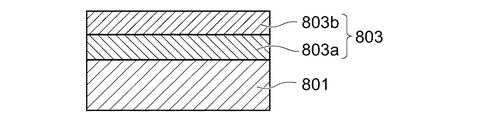
FIG. 3 is a schematic cross-sectional view illustrating an example of the photocatalyst layer.
図1に表したトイレ装置10は、洋式腰掛便器(以下説明の便宜上、単に「便器」と称する)800と、その上に設けられた衛生洗浄装置100と、を備える。衛生洗浄装置100は、ケーシング400と、便座200と、便蓋300と、を有する。便座200と便蓋300とは、ケーシング400に対して開閉自在にそれぞれ軸支されている。但し、ケーシング400は、必ずしも設けられていなくともよい。例えば、便座200と便蓋300とは、便器800に対して開閉自在にそれぞれ軸支されていてもよい。
The
便器800は、ボウル部801を有する。便蓋300が閉じている状態では、ボウル部801は、便蓋300により覆われる。ボウル部801の表面には、光触媒層(「光触媒膜」ともいう)803が形成されている。
本願明細書において、「光触媒」とは、光を照射すると、酸化作用および還元作用の少なくともいずれかが促進されるものをいう。その結果、雑菌や細菌や臭気物質などの有機物を分解する分解作用と、表面が水に濡れやすい親水作用と、菌の繁殖を抑制するあるいは菌の活動を停止させる抗菌作用と、を得ることができる。光触媒層803が形成されたボウル部801は、汚物の付着を抑制したり、汚物を分解したり、付着した水垢を容易に除去できるため、便器800の清掃負担を軽減し、きれいな便器800を維持することができる。
The
In the present specification, “photocatalyst” refers to a substance that promotes at least one of an oxidizing action and a reducing action when irradiated with light. As a result, it is possible to obtain a decomposing action for decomposing organic substances such as bacteria, bacteria and odorous substances, a hydrophilic action that easily wets the surface with water, and an antibacterial action that suppresses the growth of bacteria or stops the activity of bacteria. it can. The
具体的には、光触媒層803が形成されたボウル部801の表面に紫外線を照射すると、その紫外線および空気中の水や酸素などにより、ボウル部801の表面に活性酸素が発生する。その活性酸素は、ボウル部801の表面に付着した汚れや雑菌や細菌や臭気物質などを分解する。また、その活性酸素は、揮発性有機化合物(VOC:Volatile Organic Compounds)なども分解する。そのため、光触媒の分解作用により、ボウル部801の表面の抗菌や防汚や防臭を行うことができる。
Specifically, when the surface of the
また、光触媒層803が形成されたボウル部801の表面に紫外線を照射すると、その表面には周囲の水との結合による親水基(−OH)が表出する。これにより、ボウル部801の表面は、水になじむようになり、濡れやすくなる(親水作用)。すなわち、ボウル部801の表面には水滴ができず、水が表面に濡れ広がるようになる。そして、予めボウル部801の表面を親水化することにより、汚れは、ボウル部801の表面に濡れ広がった水の表面に付着することになる。さらに、ボウル部801の洗浄に用いる洗浄水がボウル部801の表面とその表面に付着した汚れとの間に入り込み、汚れを浮かして流す。そのため、光触媒の親水作用により、ボウル部801の表面の防汚や防曇が可能となる。
Further, when the surface of the
これらによれば、紫外線の照射と、光触媒の分解作用、親水作用および抗菌作用と、の相乗効果により効果的にボウル部801の抗菌や防汚や防臭を行うことができる。このような「光触媒」の材料としては、例えば、金属の酸化物を用いることができる。そのような酸化物としては、例えば、酸化チタン(TiOx)、酸化亜鉛(ZnOx)、酸化スズ(SnOx)、酸化ジルコニウム(ZrOx)などを挙げることができる。これらのうちでも、特に、酸化チタンは、光触媒として活性であり、また、安定性や安全性などの点でも優れる。
According to these, the antibacterial effect, antifouling and deodorizing of the
例えば、図3に表したように、光触媒層803は、バリア層803aと、機能層803bと、を有する。例えば、光触媒層803としては、TiO2/ZrO2系触媒焼成膜が用いられる。例えば、バリア層803aにおけるTiO2とZrO2との配合比率は、機能層803bにおけるTiO2とZrO2との配合比率とそれぞれ異なる。但し、図3に表した光触媒層803は、一例である。本実施形態の光触媒層803は、これだけに限定されるわけではない。
For example, as illustrated in FIG. 3, the
図1に表したように、便蓋300は、光源装置310を有する。光源装置310は、便蓋300の内部に設けられている。但し、光源装置310の設置形態は、これだけに限定されるわけではない。例えば、光源装置310は、ケーシング400の内部に設けられていてもよいし、ケーシング400の表面に付設されていてもよい。光源装置310は、ボウル部801に紫外線を照射することができる。光源装置310としては、例えば冷陰極管やLED(Light Emitting Diode)などが用いられる。
As shown in FIG. 1, the
図2に表したように、例えばケーシング400の内部には、制御部410と、入室検知センサ(人体検知手段)402と、人体検知センサ(人体検知手段)403と、着座検知センサ(人体検知手段)404と、便蓋開閉検知センサ405と、便蓋開閉駆動装置420と、が設けられている。制御部410は、例えば入室検知センサ402、人体検知センサ403あるいは着座検知センサ404から送信される検知信号に基づいて制御信号を送信し、便蓋開閉駆動装置420あるいは光源装置310の動作を制御することができる。
As shown in FIG. 2, for example, inside the
入室検知センサ402は、トイレルームのドアを開けて入室した直後の使用者や、トイレルームに入室しようとしてドアの前に存在する使用者を検知することができる。つまり、入室検知センサ402は、トイレルームに入室した使用者だけではなく、トイレルームに入室する前の使用者、すなわちトイレルームの外側のドアの前に存在する使用者を検知することができる。このような入室検知センサ402としては、焦電センサや、ドップラーセンサなどのマイクロ波センサなどを用いることができる。マイクロ波のドップラー効果を利用したセンサや、マイクロ波を送信し反射したマイクロ波の振幅(強度)に基づいて被検知体を検出するセンサなどを用いた場合、トイレルームのドア越しに使用者の存在を検知することが可能となる。つまり、トイレルームに入室する前の使用者を検知することができる。
The
人体検知センサ403は、便器800の前方にいる使用者、すなわち便座200から前方へ離間した位置に存在する使用者を検知することができる。つまり、人体検知センサ403は、トイレルームに入室して便座200に近づいてきた使用者を検知することができる。このような人体検知センサ403としては、例えば、赤外線投受光式の測距センサなどを用いることができる。
The human
着座検知センサ404は、使用者が便座200に着座する直前において便座200の上方に存在する人体や、便座200に着座した使用者を検知することができる。すなわち、着座検知センサ404は、便座200に着座した使用者だけではなく、便座200の上方に存在する使用者を検知することができる。このような着座検知センサ404としては、例えば、赤外線投受光式の測距センサなどを用いることができる。
The
便蓋開閉検知センサ405は、便蓋300の開閉状態を検知することができる。便蓋開閉検知センサ405としては、例えば、ホールICと磁石との組み合わせ、またはマイクロスイッチなどが用いられる。
便蓋開閉駆動装置420は、制御部410から送信された信号に基づいて便蓋300を開いたり閉じたりすることができる。
The toilet lid opening /
The toilet lid opening /
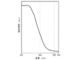
図4は、本実施形態の光触媒層の吸光特性の一例を例示するグラフ図である。
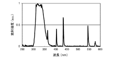
図5は、冷陰極管のスペクトルの一例を例示するグラフ図である。
図4に表したグラフ図の横軸は、波長(ナノメートル:nm)を表す。図4の表したグラフ図の縦軸は、吸光特性(任意単位:a.u.)を表す。
図5に表したグラフ図の横軸は、冷陰極管が放射する光の波長(nm)を表す。図5に表したグラフ図の縦軸は、冷陰極管が放射する光の強度(a.u.)を表す。
FIG. 4 is a graph illustrating an example of the light absorption characteristics of the photocatalyst layer of this embodiment.
FIG. 5 is a graph illustrating an example of the spectrum of a cold cathode tube.
The horizontal axis of the graph shown in FIG. 4 represents the wavelength (nanometer: nm). 4 represents the light absorption characteristic (arbitrary unit: au).
The horizontal axis of the graph shown in FIG. 5 represents the wavelength (nm) of light emitted from the cold cathode tube. The vertical axis of the graph shown in FIG. 5 represents the intensity (au) of light emitted from the cold cathode fluorescent lamp.
図4に表したように、本実施形態の光触媒層803は、波長が約388nm以下の紫外線をより多く吸収する特性を有し、波長が約388nmよりも長い紫外線の大半を吸収できない。そのため、波長が約388nmよりも長い紫外線の大半の光エネルギーが無駄になる。つまり、本実施形態の光触媒層803は、波長が約388nm以下の紫外線が照射されると励起され、光触媒活性を発現する。また、本実施形態の光触媒層803は、波長が300nm以上の紫外線において、波長が相対的に短い紫外線に対して相対的に高い励起効率(吸光特性)を有する。
As shown in FIG. 4, the
そのため、光源装置310が比較的短い波長の紫外線をボウル部801に照射すると、ボウル部801の励起効率は、比較的高くなる。これによれば、光触媒層803の光触媒活性を効率的に発現させ、分解作用、親水作用および抗菌作用を得ることができる。そのため、分解作用、親水作用および抗菌作用を考慮すると、光源装置310は、比較的短い波長の紫外線をボウル部801に照射することがより望ましい。
For this reason, when the
一方で、比較的短い波長の紫外線については、人体に影響を及ぼしたり、樹脂を変色あるいは劣化させることが知れられている。そのため、人体への影響や、樹脂の変色あるいは劣化などを考慮すると、光源装置310は、比較的長い波長の紫外線をボウル部801に照射することがより望ましい。
On the other hand, it is known that ultraviolet rays having a relatively short wavelength affect the human body and cause discoloration or deterioration of the resin. Therefore, it is more desirable that the
そこで、例えば図5に表したように、本実施形態の光源装置310は、360nm以下の波長に極大を有する紫外線を放射する。そして、光源装置310は、人体検知手段から送信された検知信号に基づいて制御部410が送信した信号により、360nm以下の波長に極大を有する紫外線をボウル部801に照射する。
Therefore, for example, as illustrated in FIG. 5, the
これによれば、紫外線による人体への影響を抑制することができるとともに、励起効率が比較的高い波長の紫外線をボウル部801に照射することができる。そのため、紫外線の照射時間を比較的短くすることができる。これにより、光源装置310の長寿命化を実現することができる。また、清潔なトイレ装置を提供することができる。
According to this, it is possible to suppress the influence of the ultraviolet rays on the human body, and it is possible to irradiate the
あるいは、本実施形態の光源装置310は、280nm以上、360nm以下の波長に極大を有する紫外線をボウル部801に照射する。
これによれば、人体検知手段が誤検知した場合であっても、日焼けを起しやすいと言われているUV−Cの波長である280nm以下の紫外線が人体に照射されることがないので、紫外線による人体への影響をより確実に抑制することができる。
Or the
According to this, even when the human body detecting means detects erroneously, the human body is not irradiated with ultraviolet rays of 280 nm or less, which is the wavelength of UV-C, which is said to be easily tanned. The influence on the human body by ultraviolet rays can be more reliably suppressed.
あるいは、本実施形態の光源装置310は、310nm以上、360nm以下の波長に極大を有する紫外線をボウル部801に照射する。
これによれば、樹脂の変色あるいは劣化を抑制することができる。
すなわち、便座200、便蓋300およびケーシング400は、一般的に、例えばポリプロピレン(PP)などの樹脂により形成される。樹脂材料は、紫外線の照射により変色したり劣化することがある。例えばポリプロピレンは、波長が310nm以下の紫外線を照射されると劣化するおそれがあることが知れられている(非特許文献−プラスチックス−Vol.55、No.5−プラスチックの実用強さと耐久性8、あるいは非特許文献−促進暴露試験ハンドブック−日本ウエザリングテストセンターなど)。
これに対して、本実施形態の光源装置310は、310nm以上、360nm以下の波長に極大を有する紫外線をボウル部801に照射する。そのため、便座200、便蓋300およびケーシング400の変色あるいは劣化を抑制することができる。
Or the
According to this, discoloration or deterioration of the resin can be suppressed.
That is, the
On the other hand, the
なお、樹脂の変色あるいは劣化を抑制する被覆を便座200、便蓋300およびケーシング400に施すことも一策である。但し、便座200、便蓋300およびケーシング400の成型性、コストおよび現実性などを考慮すると、310nm以上、360nm以下の波長に極大を有する紫外線がボウル部801に照射されることがより望ましい。
紫外線の波長の詳細については、後述する。
Note that it is also possible to apply a coating that suppresses discoloration or deterioration of the resin to the
Details of the wavelength of the ultraviolet rays will be described later.
図6は、紫外線殺菌作用の波長特性を表すグラフ図である。
図6に表したグラフ図の横軸は、紫外線の波長(nm)を表す。図6に表したグラフ図の縦軸は、殺菌力相対値を表す。図6に表したグラフ図は、国際的に標準のものとして認められているものである(非特許文献)。
FIG. 6 is a graph showing the wavelength characteristics of the ultraviolet germicidal action.
The horizontal axis of the graph shown in FIG. 6 represents the wavelength (nm) of ultraviolet rays. The vertical axis of the graph shown in FIG. 6 represents the bactericidal power relative value. The graph shown in FIG. 6 is internationally recognized as a standard (non-patent document).
一般的に、所定の波長の紫外線を照射すると、殺菌効果が得られる。つまり、広く一般的に、紫外線殺菌が知られている。本発明者が得た知見によれば、平板上に存在する大腸菌の99.9パーセント(%)を殺すために必要な紫外線の照射エネルギーは、90マイクロワット・分/平方センチメートル(μW・min/cm2)である(非特許文献−(社)照明学会誌:第36巻 第3号−論文『殺菌灯による水の消毒』河端俊治、原田常雄)。これによれば、光源装置310が紫外線を60分間照射する場合には、必要な紫外線の強度は、次式で表される。
(90μW・min/cm2)/60min=1.5μW/cm2
Generally, when irradiating ultraviolet rays having a predetermined wavelength, a bactericidal effect is obtained. That is, ultraviolet sterilization is generally known. According to the knowledge obtained by the present inventor, the irradiation energy of ultraviolet rays necessary for killing 99.9% (%) of E. coli present on the plate is 90 microwatts / minute / square centimeter (μW · min / cm). 2 ) (Non-Patent Document-Journal of the Illuminating Society of Japan: Vol. 36, No. 3, paper "Disinfection of water with germicidal lamps" Toshiharu Kawabata, Tsuneo Harada). According to this, when the
(90 μW · min / cm 2 ) / 60 min = 1.5 μW / cm 2
ここで、図6に表したように、殺菌作用の最大値を示す波長は、253.7nmである。図6に表した波長特性によれば、波長が310nmの紫外線の殺菌効果は、波長が253.7nmの紫外線の殺菌効果の約0.002倍程度となる。すると、波長が310nmの紫外線を光源装置310が放射する場合には、平板上に存在する大腸菌の99.9%を殺すために必要な紫外線の強度は、次式で表される。
(1.5μW/cm2)/0.002=750μW/cm2
つまり、波長が310nmの紫外線であって強度が750μW/cm2以上の紫外線を光源装置310が放射すると、平板上に存在する大腸菌の99.9%を殺すことができる。
Here, as shown in FIG. 6, the wavelength indicating the maximum value of the bactericidal action is 253.7 nm. According to the wavelength characteristics shown in FIG. 6, the sterilizing effect of ultraviolet light having a wavelength of 310 nm is about 0.002 times the sterilizing effect of ultraviolet light having a wavelength of 253.7 nm. Then, when the
(1.5 μW / cm 2 ) /0.002=750 μW / cm 2
That is, when the
図1〜図5に関して前述したように、本実施形態のボウル部801の表面には、光触媒層803が形成されている。そして、光源装置310が比較的短い波長の紫外線をボウル部801に照射すると、光触媒層803の光触媒活性を効率的に発現させ、抗菌作用を得ることができる。これにより、光源装置310は、波長が310nmの紫外線を放射する場合には、紫外線の殺菌作用と光触媒の抗菌作用との相乗効果により、強度が750μW/cm2以下の紫外線を放射することでボウル部801の表面を殺菌することができる。
As described above with reference to FIGS. 1 to 5, the
なお、上述の式にて示しているように、波長が310nmよりも長い紫外線を照射する場合には、紫外線のみで大腸菌の99.9%を殺すことができる強度は、750μW/cm2よりも大きくなる。本実施形態においては、紫外線の殺菌作用と光触媒の抗菌作用との相乗効果により、310nm以上、360nm以下の波長に極大を有する紫外線を照射する場合においても、強度が750μW/cm2以下の紫外線を照射することで、ボウル部801の表面を殺菌することができる。
In addition, as shown in the above formula, when irradiating ultraviolet rays having a wavelength longer than 310 nm, the intensity capable of killing 99.9% of E. coli by ultraviolet rays alone is higher than 750 μW / cm 2. growing. In the present embodiment, due to the synergistic effect of the ultraviolet germicidal action and the antibacterial action of the photocatalyst, ultraviolet light having an intensity of 750 μW / cm 2 or less is applied even when irradiating ultraviolet light having a maximum at a wavelength of 310 nm to 360 nm. By irradiating, the surface of the
次に、本実施形態にかかるトイレ装置の動作の具体例について、図面を参照しつつ説明する。
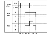
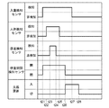
図7は、本実施形態にかかるトイレ装置の動作の具体例を例示するタイミングチャート図である。
Next, a specific example of the operation of the toilet apparatus according to the present embodiment will be described with reference to the drawings.
FIG. 7 is a timing chart illustrating a specific example of the operation of the toilet apparatus according to this embodiment.
例えば使用者がトイレルームに入室すると、入室検知センサ402は、トイレルームに入室した人体を検知し制御部410へ信号を送信する(タイミングt1)。その後、使用者が排泄行為を終了しトイレルームから退室すると、入室検知センサ402は、トイレルームに人体が存在しないことを検知し制御部410へ信号を送信する(タイミングt2)。
For example, when the user enters the toilet room, the
それと同時にあるいは所定時間が経過すると、光源装置310は、制御部410から送信された信号に基づいて、図4および図5に関して前述した波長の紫外線をボウル部801に照射する(タイミングt3)。光源装置310は、制御部410から送信された信号に基づいて、紫外線をボウル部801に照射してから所定時間(例えば約1時間程度)が経過すると、ボウル部801への紫外線の照射を停止する(タイミングt4)。続いて、タイミングt5〜t8の動作は、タイミングt1〜t4に関して前述した動作と同様である。
At the same time or when a predetermined time elapses, the
本具体例によれば、トイレ装置10が使用される度に、光源装置310は、前述した波長の紫外線をボウル部801に照射する。これにより、光触媒層803が光触媒活性を発現し、ボウル部801の表面の親水性を維持することができる。また、清潔なトイレ装置を提供することができる。
According to this specific example, every time the
図8は、本実施形態にかかるトイレ装置の動作の他の具体例を例示するタイミングチャート図である。
タイミングt11〜t13の動作は、図7に関して前述した具体例のタイミングt1〜t3の動作と同様である。
FIG. 8 is a timing chart illustrating another specific example of the operation of the toilet apparatus according to this embodiment.
The operations at timings t11 to t13 are the same as the operations at timings t1 to t3 in the specific example described above with reference to FIG.
続いて、光源装置310が紫外線を照射中に例えば使用者がトイレルームに入室すると、ボウル部801に照射される光は、制御部410から送信された信号に基づいて、照射中の紫外線の波長よりも長い波長の光に変更される(タイミングt14)。例えば、光源装置310が紫外線を照射中に例えば使用者がトイレルームに入室すると、制御部410は、光源装置310からの紫外線の照射を停止させ、光源装置310とは異なる他の光源から照射中の紫外線の波長よりも長い波長の光をボウル部801に照射させる。
Subsequently, for example, when the user enters the toilet room while the
続いて、光源装置310が紫外線を照射中に例えば使用者がトイレルームから退室すると、ボウル部801に照射される光は、制御部410から送信された信号に基づいて、照射中の紫外線の波長よりも短い波長の紫外線に変更される(タイミングt15)。続いて、光源装置310は、制御部410から送信された信号に基づいて、紫外線をボウル部801に照射してから所定時間(例えば約1時間程度)が経過すると、ボウル部801への紫外線の照射を停止する(タイミングt16)。
Subsequently, for example, when the user leaves the toilet room while the
本具体例によれば、例えば公共施設などのように使用頻度が比較的高いトイレルームにおいて、比較的長い時間にわたってボウル部801に紫外線を照射することができる。そのため、光触媒層803の励起状態を維持し、清潔なトイレ装置を維持することができる。
According to this specific example, the
図9は、本実施形態にかかるトイレ装置の動作のさらに他の具体例を例示するタイミングチャート図である。 FIG. 9 is a timing chart illustrating yet another specific example of the operation of the toilet apparatus according to this embodiment.
例えば使用者がトイレルームに入室すると、入室検知センサ402は、トイレルームに入室した人体を検知し制御部410へ信号を送信する(タイミングt21)。すると、便蓋開閉駆動装置420は、制御部410から送信された信号に基づいて便蓋300を開く。これにより、便蓋開閉検知センサ405は、便蓋300が開いたことを検知する(タイミングt21)。
For example, when the user enters the toilet room, the
続いて、使用者が便器800に近づき便器800の前方に立つと、人体検知センサ403は、便器800の前方にいる人体を検知し制御部410へ信号を送信する(タイミングt22)。続いて、使用者が便座200に着座すると、着座検知センサ404は、便座200に着座した使用者を検知する(タイミングt23)。
Subsequently, when the user approaches the
なお、使用者は、便器800の前に立ったままで小便を行うことがある。この場合には、着座検知センサ404は、人体を検知しない。以下、図9に表した具体例では、使用者が便座200に着座する場合を例に挙げる。
Note that the user may perform urination while standing in front of the
続いて、使用者は、排泄行為を終了した後、便座200から離座し、便器800の前方から離れる。すると、着座検知センサ404は、使用者が便座200に着座していないことを検知し制御部410へ信号を送信する(タイミングt24)。人体検知センサ403は、使用者が便器800の前方にいないことを検知し制御部410へ信号を送信する(タイミングt25)。
Subsequently, after finishing the excretion action, the user leaves the
それと同時にあるいは所定時間が経過すると、便蓋開閉駆動装置420は、制御部410から送信された信号に基づいて便蓋300を閉じる。これにより、便蓋開閉検知センサ405は、便蓋300が閉じたことを検知する(タイミングt26)。また、光源装置310は、制御部410から送信された信号に基づいて、図4および図5に関して前述した波長の紫外線をボウル部801に照射する(タイミングt26)。
At the same time or when a predetermined time has elapsed, the toilet lid opening /
使用者がトイレルームから退室すると、入室検知センサ402は、トイレルームに人体が存在しないことを検知し制御部410へ信号を送信する(タイミングt27)。光源装置310は、制御部410から送信された信号に基づいて、紫外線をボウル部801に照射してから所定時間(例えば約1時間程度)が経過すると、ボウル部801への紫外線の照射を停止する(タイミングt28)。
When the user leaves the toilet room, the
本具体例によれば、光源装置310は、便蓋300が閉じた状態で前述した波長の紫外線をボウル部801に照射する。例えば、光源装置310は、使用者がトイレルームにいる場合でも、便蓋300が閉じた状態で紫外線を照射する。これによれば、便蓋300がボウル部801を覆っているため、紫外線による人体への影響を抑制するとともに、トイレ装置10が使用された後のより早い段階で紫外線をボウル部801に照射することができる。そのため、トイレ装置10が使用された後のより早い段階で、光触媒層803が光触媒活性を発現し、光触媒層803の励起状態を維持することができる。また、清潔なトイレ装置を提供することができる。
According to this specific example, the
次に、本発明者が紫外線の波長について検討した結果について、図面を参照しつつ説明する。
図10は、本発明者が光触媒層の分解作用について検討した検討方法を説明する模式的斜視図である。
図11は、本発明者が光触媒層の分解作用について検討した検討結果を表すグラフ図である。
図11に表したグラフ図の横軸は、紫外線の照射時間(a.u.)を表す。図11に表したグラフ図の縦軸は、光の反射強度の計測値(a.u.)を表す。
Next, the result of the study of the wavelength of ultraviolet rays by the present inventor will be described with reference to the drawings.
FIG. 10 is a schematic perspective view for explaining a study method in which the inventor examined the decomposition action of the photocatalyst layer.
FIG. 11 is a graph showing the result of examination conducted by the inventor on the decomposition action of the photocatalyst layer.
The horizontal axis of the graph shown in FIG. 11 represents ultraviolet irradiation time (au). The vertical axis of the graph shown in FIG. 11 represents the measured value (au) of the light reflection intensity.
本発明者は、光触媒層の分解作用の検討にあたり、タイル501およびインク503を用意した。タイル501の表面には、光触媒層803が形成されている。つまり、本検討のタイル501の表面の性状は、本実施形態のボウル部801の表面の性状と同様である。図10に表したように、本発明者は、タイル501の表面にインク503を塗布した。
The present inventor prepared the
続いて、本発明者は、インク503が塗布された部分を含む領域に対して光源装置310から紫外線を照射させた。本検討では、光源装置310としてLEDを使用した。本発明者は、340nm以下の波長に極大を有する紫外線と、365nm以下の波長に極大を有する紫外線と、を光源装置310からそれぞれ照射させた。
Subsequently, the inventor irradiates the region including the portion where the
光源装置310から照射された紫外線の強度は、340nm以下の波長に極大を有する紫外線および365nm以下の波長に極大を有する紫外線ともに、約300マイクロワット/平方センチメートル(μW/cm2)である。紫外線の強度については、約300〜410nm程度の波長に対してほぼ100%の値を計測可能な光強度センサを用いて計測した。具体的には、本検討では、「浜松ホトニクス製 C9256−01−H9958」のUVメータを用いて紫外線の強度を測定した。
The intensity of ultraviolet rays emitted from the
紫外線の照射時間は、例えば約100〜300秒間程度である。図11に表したグラフ図の横軸の「初期」とは、紫外線を照射する前の状態を例示している。 The irradiation time of ultraviolet rays is, for example, about 100 to 300 seconds. “Initial” on the horizontal axis of the graph shown in FIG. 11 exemplifies a state before irradiation with ultraviolet rays.
続いて、図10に表したように、本発明者は、インク503が塗布された部分に対して赤外線発光装置511から赤外線を照射させ、反射した光の強度を光強度センサ513により測定した。光の反射強度の測定結果は、図11に表した通りである。図11に表したグラフ図の中の「360nm」の値は、例えば図4に表した光触媒層の吸光特性と、340nm以下の波長に極大を有する紫外線および365nm以下の波長に極大を有する紫外線と、を用いて補間した値である。図11に表したグラフ図の中の「無照射」の値は、インク503が塗布された部分を含む領域に対して紫外線を照射させていない場合の値である。
Subsequently, as shown in FIG. 10, the inventor measured the intensity of the reflected light by using the
インク503が塗布されていないタイル501において反射する光の強度は、インク503が塗布されたタイル501において反射する光の強度よりも高い。そのため、インク503がより分解されると、インク503が塗布された部分において反射する光の強度は、より高くなる。
The intensity of light reflected by the
図11に表したグラフ図によれば、相対的に短い波長の紫外線を照射させた場合の反射強度は、相対的に長い波長の紫外線を照射させた場合の反射強度よりも高い。つまり、相対的に短い波長の紫外線を照射させた場合のインクの分解量は、相対的に長い波長の紫外線を照射させた場合のインクの分解量よりも多い。そのため、分解作用を考慮すると、光源装置310は、比較的短い波長の紫外線をボウル部801に照射することがより望ましい。
According to the graph shown in FIG. 11, the reflection intensity when irradiated with ultraviolet rays having a relatively short wavelength is higher than the reflection intensity when irradiated with ultraviolet rays having a relatively short wavelength. That is, the amount of ink decomposed when irradiated with relatively short wavelength ultraviolet light is larger than the amount of ink decomposed when irradiated with relatively long wavelength ultraviolet light. Therefore, considering the decomposition action, it is more desirable that the
図12は、本発明者が光触媒層の親水作用について検討した検討方法を説明する模式的平面図である。
図13は、本発明者が光触媒層の親水作用について検討した検討結果を表すグラフ図である。
図13に表したグラフ図の横軸は、紫外線の照射時間(a.u.)を表す。図13に表したグラフ図の縦軸は、接触角(°)を表す。
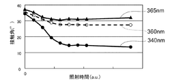
FIG. 12 is a schematic plan view for explaining a study method in which the inventors have studied the hydrophilic action of the photocatalyst layer.
FIG. 13 is a graph showing the result of examination conducted by the inventor on the hydrophilic action of the photocatalyst layer.
The horizontal axis of the graph shown in FIG. 13 represents the ultraviolet irradiation time (au). The vertical axis of the graph shown in FIG. 13 represents the contact angle (°).
本発明者は、光触媒層の親水作用の検討にあたり、タイル501および水505を用意した。タイル501の表面には、光触媒層803が形成されている。つまり、本検討のタイル501の表面の性状は、本実施形態のボウル部801の表面の性状と同様である。
The present inventor prepared a
続いて、本発明者は、タイル501の表面に対して光源装置310から紫外線を照射させた。本検討では、光源装置310としてLEDを使用した。本発明者は、340nm以下の波長に極大を有する紫外線と、365nm以下の波長に極大を有する紫外線と、を光源装置310からそれぞれ照射させた。
Subsequently, the inventor irradiates the surface of the
光源装置310から照射された紫外線の強度は、340nm以下の波長に極大を有する紫外線および365nm以下の波長に極大を有する紫外線ともに、約100μW/cm2である。本検討では、「浜松ホトニクス製 C9256−01−H9958」のUVメータを用いて紫外線の強度を測定した。
紫外線の照射時間は、例えば約100〜400分間程度である。
The intensity of ultraviolet light emitted from the
The irradiation time of ultraviolet rays is about 100 to 400 minutes, for example.
図12に表したように、本発明者は、タイル501の表面に水505を滴下した。そして、本発明者は、タイル501の表面における水505の接触角θを測定した。本願明細書において「接触角」とは、所定の固体表面(本検討ではタイル501の表面)と液体表面(本検討では水505の表面)との界面において、固体表面と液体表面とがなす角度であって液体の側で測定される角度をいうものとする。また、接触角θについては、接触角計「協和界面化学(株)製、自動接触角計DM−500」を用いて測定した。
As shown in FIG. 12, the inventor dropped
接触角θの測定結果は、図13に表した通りである。図13に表したグラフ図の中の「360nm」の値は、例えば図4に表した光触媒層の吸光特性と、340nm以下の波長に極大を有する紫外線および365nm以下の波長に極大を有する紫外線と、を用いて補間した値である。 The measurement result of the contact angle θ is as shown in FIG. The value of “360 nm” in the graph shown in FIG. 13 indicates, for example, the absorption characteristics of the photocatalyst layer shown in FIG. 4, ultraviolet light having a maximum at a wavelength of 340 nm or less, and ultraviolet light having a maximum at a wavelength of 365 nm or less. This is the value interpolated using.
固体表面がより高い親水性を有する場合の接触角θは、固体表面がより低い親水性を有する場合の接触角θよりも小さい。そのため、タイル501の表面がより高い親水性を有すると、タイル501の表面における水505の接触角θは、より小さくなる。
The contact angle θ when the solid surface has higher hydrophilicity is smaller than the contact angle θ when the solid surface has lower hydrophilicity. Therefore, when the surface of the
図13に表したグラフ図によれば、相対的に短い波長の紫外線を照射させた場合の接触角θは、相対的に長い波長の紫外線を照射させた場合の接触角θよりも小さい。つまり、相対的に短い波長の紫外線を照射させた場合の親水性は、相対的に長い波長の紫外線を照射させた場合の親水性よりも高い。本発明者の検討の結果、固体表面における水の接触角θが30度以下である場合には、固体表面において水膜を形成可能であることが分かっている。そのため、本実施形態の光源装置310は、360nm以下の波長に極大を有する紫外線を放射することがより好ましい。
According to the graph shown in FIG. 13, the contact angle θ when irradiated with ultraviolet rays having a relatively short wavelength is smaller than the contact angle θ when irradiated with ultraviolet rays having a relatively long wavelength. That is, the hydrophilicity when irradiated with ultraviolet rays having a relatively short wavelength is higher than the hydrophilicity when irradiated with ultraviolet rays having a relatively long wavelength. As a result of the study by the present inventors, it has been found that a water film can be formed on the solid surface when the contact angle θ of water on the solid surface is 30 degrees or less. Therefore, it is more preferable that the
以上、本発明の実施の形態について説明した。しかし、本発明はこれらの記述に限定されるものではない。前述の実施の形態に関して、当業者が適宜設計変更を加えたものも、本発明の特徴を備えている限り、本発明の範囲に包含される。例えば、便蓋300および便器800などが備える各要素の形状、寸法、材質、配置などや光源装置310の設置形態などは、例示したものに限定されるわけではなく適宜変更することができる。
また、前述した各実施の形態が備える各要素は、技術的に可能な限りにおいて組み合わせることができ、これらを組み合わせたものも本発明の特徴を含む限り本発明の範囲に包含される。
The embodiment of the present invention has been described above. However, the present invention is not limited to these descriptions. As long as the features of the present invention are provided, those skilled in the art appropriately modified the design of the above-described embodiments are also included in the scope of the present invention. For example, the shape, size, material, arrangement, and the like of each element included in the
Moreover, each element with which each embodiment mentioned above is provided can be combined as long as technically possible, and the combination of these is also included in the scope of the present invention as long as it includes the features of the present invention.
10 トイレ装置、 100 衛生洗浄装置、 200 便座、 300 便蓋、 310 光源装置、 400 ケーシング、 402 入室検知センサ、 403 人体検知センサ、 404 着座検知センサ、 405 便蓋開閉検知センサ、 410 制御部、 420 便蓋開閉駆動装置、 501 タイル、 503 インク、 505 水、 511 赤外線発光装置、 513 光強度センサ、 800 便器、 801 ボウル部、 803 光触媒層、 803a バリア層、 803b 機能層
DESCRIPTION OF
Claims (7)
トイレルーム内の人体の有無を検知する人体検知手段と、
を備え、
前記光源装置は、前記人体検知手段が前記トイレルーム内に人体が存在しないことを検知した場合において、360nm以下の波長に極大を有する紫外線を前記ボウル部に照射することを特徴とするトイレ装置。 A light source device capable of irradiating ultraviolet rays onto a bowl portion of a toilet bowl on which a photocatalytic film is formed;
Human body detection means for detecting the presence or absence of a human body in the toilet room;
With
The light source device irradiates the bowl portion with ultraviolet light having a maximum at a wavelength of 360 nm or less when the human body detecting means detects that no human body is present in the toilet room.
開閉自在に設けられた便蓋であって閉じた状態で前記ボウル部を覆う便蓋の開閉状態を検知する便蓋開閉検知手段と、
を備え、
前記光源装置は、前記便蓋が閉じた状態であることを前記便蓋開閉検知手段が検知した場合において、360nm以下の波長に極大を有する紫外線を前記ボウル部に照射することを特徴とするトイレ装置。 A light source device capable of irradiating ultraviolet rays onto a bowl portion of a toilet bowl on which a photocatalytic film is formed;
A toilet lid open / close detection means for detecting an open / closed state of a toilet lid that is a toilet lid that is freely opened and closed and covers the bowl portion in a closed state;
With
The light source device irradiates the bowl portion with ultraviolet light having a maximum at a wavelength of 360 nm or less when the toilet lid opening / closing detection means detects that the toilet lid is in a closed state. apparatus.
前記ボウル部に照射される光は、前記照射中の紫外線の波長も長い波長の光に変更されることを特徴とする請求項1および3〜6のいずれか1つに記載のトイレ装置。 When the human body detecting means detects that a human body exists in the toilet room while the light source device irradiates the bowl portion with ultraviolet rays,
The toilet device according to any one of claims 1 and 3 to 6, wherein the light applied to the bowl portion is changed to light having a longer wavelength than the wavelength of the ultraviolet rays being irradiated.
Priority Applications (1)
| Application Number | Priority Date | Filing Date | Title |
|---|---|---|---|
| JP2013039115A JP2014167224A (en) | 2013-01-30 | 2013-02-28 | Toilet apparatus |
Applications Claiming Priority (3)
| Application Number | Priority Date | Filing Date | Title |
|---|---|---|---|
| JP2013015956 | 2013-01-30 | ||
| JP2013015956 | 2013-01-30 | ||
| JP2013039115A JP2014167224A (en) | 2013-01-30 | 2013-02-28 | Toilet apparatus |
Publications (2)
| Publication Number | Publication Date |
|---|---|
| JP2014167224A true JP2014167224A (en) | 2014-09-11 |
| JP2014167224A5 JP2014167224A5 (en) | 2016-04-14 |
Family
ID=51617038
Family Applications (1)
| Application Number | Title | Priority Date | Filing Date |
|---|---|---|---|
| JP2013039115A Pending JP2014167224A (en) | 2013-01-30 | 2013-02-28 | Toilet apparatus |
Country Status (1)
| Country | Link |
|---|---|
| JP (1) | JP2014167224A (en) |
Cited By (2)
| Publication number | Priority date | Publication date | Assignee | Title |
|---|---|---|---|---|
| JP2018190604A (en) * | 2017-05-08 | 2018-11-29 | 岩崎電気株式会社 | UVLED irradiation system |
| JP7431484B1 (en) | 2023-12-21 | 2024-02-15 | こずえ 永野 | toilet equipment |
Citations (6)
| Publication number | Priority date | Publication date | Assignee | Title |
|---|---|---|---|---|
| JPH1171803A (en) * | 1997-08-27 | 1999-03-16 | Inax Corp | Toilet room |
| JP2002167235A (en) * | 2000-11-29 | 2002-06-11 | Okaya Electric Ind Co Ltd | Uv discharge lamp for photocatalyst |
| JP2004305460A (en) * | 2003-04-08 | 2004-11-04 | Inax Corp | Tooth brush sterilization device and tooth brush housing case |
| JP3111579U (en) * | 2005-04-05 | 2005-07-28 | コトヒラ工業株式会社 | Slipper storage with sterilization / deodorization function |
| JP2010275813A (en) * | 2009-05-29 | 2010-12-09 | Toto Ltd | Toilet bowl |
| JP2012139452A (en) * | 2011-01-05 | 2012-07-26 | U-Vix Corp | Air cleaner |
-
2013
- 2013-02-28 JP JP2013039115A patent/JP2014167224A/en active Pending
Patent Citations (6)
| Publication number | Priority date | Publication date | Assignee | Title |
|---|---|---|---|---|
| JPH1171803A (en) * | 1997-08-27 | 1999-03-16 | Inax Corp | Toilet room |
| JP2002167235A (en) * | 2000-11-29 | 2002-06-11 | Okaya Electric Ind Co Ltd | Uv discharge lamp for photocatalyst |
| JP2004305460A (en) * | 2003-04-08 | 2004-11-04 | Inax Corp | Tooth brush sterilization device and tooth brush housing case |
| JP3111579U (en) * | 2005-04-05 | 2005-07-28 | コトヒラ工業株式会社 | Slipper storage with sterilization / deodorization function |
| JP2010275813A (en) * | 2009-05-29 | 2010-12-09 | Toto Ltd | Toilet bowl |
| JP2012139452A (en) * | 2011-01-05 | 2012-07-26 | U-Vix Corp | Air cleaner |
Cited By (2)
| Publication number | Priority date | Publication date | Assignee | Title |
|---|---|---|---|---|
| JP2018190604A (en) * | 2017-05-08 | 2018-11-29 | 岩崎電気株式会社 | UVLED irradiation system |
| JP7431484B1 (en) | 2023-12-21 | 2024-02-15 | こずえ 永野 | toilet equipment |
Similar Documents
| Publication | Publication Date | Title |
|---|---|---|
| JP6160810B2 (en) | Toilet equipment | |
| US10092669B2 (en) | Sterilizing radiation system for use with door handle | |
| JP5658441B2 (en) | Drainage device for sanitary equipment | |
| US20070256226A1 (en) | Toilet accessory with sterilization elements | |
| KR102056317B1 (en) | System for sterilization of toilet | |
| KR20150000852U (en) | Hand Sterilization Appapatus for Door Handle | |
| US20090256085A1 (en) | Ultra-violet sponge holder | |
| JP2020116430A (en) | Sterilization device of door knob or the like using uv ray | |
| WO2016129394A1 (en) | Toilet device | |
| JP2014167224A (en) | Toilet apparatus | |
| WO2015015734A1 (en) | Sterilization device | |
| KR20110042990A (en) | Hand drier and method for sterilization of tray of hand drier | |
| JP2010275841A (en) | Drainage device for sanitary fixture | |
| JP2014177743A (en) | Toilet apparatus | |
| JP6016115B2 (en) | Toilet equipment | |
| JP2010084353A (en) | Sanitary washing device | |
| JP7263967B2 (en) | Sink sterilizer | |
| JP6160811B2 (en) | Toilet equipment | |
| JP6459156B2 (en) | Toilet equipment | |
| JP6168468B2 (en) | Toilet equipment | |
| JP5732606B2 (en) | Drainage device for sanitary equipment | |
| JP6252824B2 (en) | Toilet equipment | |
| JP6150101B2 (en) | Toilet equipment | |
| JP6459158B2 (en) | Toilet equipment | |
| JP2014189969A (en) | Toilet device |
Legal Events
| Date | Code | Title | Description |
|---|---|---|---|
| A521 | Request for written amendment filed |
Free format text: JAPANESE INTERMEDIATE CODE: A523 Effective date: 20160224 |
|
| A621 | Written request for application examination |
Free format text: JAPANESE INTERMEDIATE CODE: A621 Effective date: 20160224 |
|
| A977 | Report on retrieval |
Free format text: JAPANESE INTERMEDIATE CODE: A971007 Effective date: 20161018 |
|
| A131 | Notification of reasons for refusal |
Free format text: JAPANESE INTERMEDIATE CODE: A131 Effective date: 20161026 |
|
| A521 | Request for written amendment filed |
Free format text: JAPANESE INTERMEDIATE CODE: A523 Effective date: 20161221 |
|
| A131 | Notification of reasons for refusal |
Free format text: JAPANESE INTERMEDIATE CODE: A131 Effective date: 20170515 |
|
| A521 | Request for written amendment filed |
Free format text: JAPANESE INTERMEDIATE CODE: A523 Effective date: 20170714 |
|
| A02 | Decision of refusal |
Free format text: JAPANESE INTERMEDIATE CODE: A02 Effective date: 20171227 |