JP2014164090A - Calibration device and control method thereof - Google Patents
Calibration device and control method thereof Download PDFInfo
- Publication number
- JP2014164090A JP2014164090A JP2013034552A JP2013034552A JP2014164090A JP 2014164090 A JP2014164090 A JP 2014164090A JP 2013034552 A JP2013034552 A JP 2013034552A JP 2013034552 A JP2013034552 A JP 2013034552A JP 2014164090 A JP2014164090 A JP 2014164090A
- Authority
- JP
- Japan
- Prior art keywords
- calibration
- luminance
- region
- image processing
- color measurement
- Prior art date
- Legal status (The legal status is an assumption and is not a legal conclusion. Google has not performed a legal analysis and makes no representation as to the accuracy of the status listed.)
- Pending
Links
Images


Abstract
Description
本発明は、前面センサを用いてキャリブレーション処理を実行するキャリブレーション装置及びその制御方法に関するものである。 The present invention relates to a calibration apparatus that executes a calibration process using a front sensor and a control method thereof.
一般的な液晶ディスプレイは液晶層を透過する光量を調節することにより画像を表示している。従来、バックライトの光量を一定に保ち、液晶層に印加する電圧を制御し、液晶の透過率を変化させることにより、液晶を透過する光量を調節していた。しかし、液晶の透過率を下げるのは限度があるため、バックライトの光量を一定に保ったままでは、液晶の透過率を最小値にしてもバックライト光量に比例した量の光が透過し、黒浮きが生じて十分なコントラストが得られなかった。そのため、画像信号に合わせてバックライト光量も調整するディミングと呼ばれる技術が開発された。 A general liquid crystal display displays an image by adjusting the amount of light transmitted through the liquid crystal layer. Conventionally, the amount of light transmitted through the liquid crystal is adjusted by keeping the light amount of the backlight constant, controlling the voltage applied to the liquid crystal layer, and changing the transmittance of the liquid crystal. However, since there is a limit to lowering the transmittance of the liquid crystal, the amount of light proportional to the amount of backlight is transmitted even if the transmittance of the liquid crystal is kept at a minimum value while keeping the light amount of the backlight constant. Black contrast occurred and sufficient contrast could not be obtained. For this reason, a technique called dimming that adjusts the amount of backlight light according to the image signal has been developed.
ディミングには画面全体を一つの制御単位としてバックライト全体の光量を変化させるグローバルディミングと、画面をいくつかの制御領域に分割し、分割した制御領域毎にバックライト光量を変化させるローカルディミング制御(以下LD制御と呼ぶ)がある。図12(A)はLD制御を適用した場合の表示画像(左)とこの時の領域毎のバックライトの光量(右)を表した図である。A11〜A46のそれぞれがLD制御におけるバックライト輝度の制御単位であり、それぞれの領域をLD領域と呼ぶ。LD制御ではLD領域毎にバックライト光量を変化させるが、LD領域の明るさは隣接するLD領域のバックライト光量の影響を受ける。隣接する領域から入ってくる光も含め、LD領域に白を表示したときの輝度を以下そのLD領域のバックライト輝度と呼ぶ。 For dimming, global dimming that changes the light intensity of the entire backlight with the entire screen as one control unit, and local dimming control that divides the screen into several control areas and changes the backlight light intensity for each divided control area ( (Hereinafter referred to as LD control). FIG. 12A is a diagram showing a display image (left) when the LD control is applied and a backlight light amount (right) for each region at this time. Each of A11 to A46 is a backlight luminance control unit in the LD control, and each area is referred to as an LD area. In the LD control, the backlight light amount is changed for each LD region, but the brightness of the LD region is affected by the backlight light amount of the adjacent LD region. The luminance when white is displayed in the LD region, including the light that enters from the adjacent region, is hereinafter referred to as the backlight luminance of the LD region.
LD制御では一般的に入力画像の垂直同期期間(以下ではV期間と呼ぶ)毎に、入力画像の統計量を取得し、統計量に基づいてLD領域毎にバックライト輝度を決定し、決定したバックライト輝度に基づいて各LD領域のバックライト光量を決定する。バックライト光量を変化させる分を信号処理により伸長することで、明るいLD領域の輝度は維持したまま、暗いLD領域の黒をより暗くすることができる。よって、画面全体で見たときの白と黒のコントラスト比を向上することができる。 In the LD control, generally, a statistic of the input image is acquired every vertical synchronization period (hereinafter referred to as V period) of the input image, and the backlight luminance is determined for each LD region based on the statistic. Based on the backlight luminance, the amount of backlight in each LD region is determined. By extending the amount by which the amount of backlight light is changed by signal processing, it is possible to darken black in the dark LD region while maintaining the luminance in the bright LD region. Therefore, the contrast ratio of white and black when viewed on the entire screen can be improved.
また、ディスプレイ前面に、液晶を透過した光を測定するセンサ(以下前面センサと呼ぶ)が組み込まれたディスプレイがある。このようなディスプレイでは、パネルに表示したパッチ画像を測色することで、画像処理パラメータを調整するキャリブレーションを行うことができる。キャリブレーションでは、ユーザが設定した目標色域、目標色温度、目標γ等に基づきディスプレイを校正する。 In addition, there is a display in which a sensor for measuring light transmitted through liquid crystal (hereinafter referred to as a front sensor) is incorporated on the front surface of the display. Such a display can perform calibration for adjusting image processing parameters by measuring the color of the patch image displayed on the panel. In calibration, the display is calibrated based on the target color gamut, target color temperature, target γ, etc. set by the user.
また、キャリブレーションを行った後、通常使用時に、前面センサでパッチ画像を測色することで、ディスプレイの状態をチェックする機能を有するディスプレイもある。このようなディスプレイでは、輝度や色度がキャリブレーション目標からずれていた場合、自動的にキャリブレーションを実行したり、キャリブレーションを促すメッセージを表示したりすることができる。 There is also a display having a function of checking the state of the display by performing color measurement of a patch image with a front sensor during normal use after calibration. In such a display, when the luminance or chromaticity is deviated from the calibration target, it is possible to automatically execute calibration or display a message prompting the calibration.
従来、LD制御を行う画像表示装置では、まず、バックライト輝度を使用しうる最大輝度(と他に数種類のバックライト輝度)に合わせた状態でキャリブレーションを行い、画像処理パラメータを作成する。そして、キャリブレーションした画像処理パラメータから推測して、他のバックライト輝度に対応する画像処理パラメータを作成していた。これは、全てのバックライト輝度でキャリブレーションして画像処理パラメータを作成する方が
精度はよいが、時間がかかるためである。バックライト輝度を順次変更して、バックライト輝度毎の画像処理パラメータを作成する方法については例えば特許文献1に記載されている。
2. Description of the Related Art Conventionally, in an image display apparatus that performs LD control, first, calibration is performed in accordance with the maximum luminance (and several other types of backlight luminance) that can use the backlight luminance, and image processing parameters are created. Then, image processing parameters corresponding to other backlight luminances are created by inferring from the calibrated image processing parameters. This is because it is more accurate to create an image processing parameter by performing calibration with all backlight luminances, but it takes time. For example,
しかしながら、上述した従来の技術では、前面センサがあるLD領域のバックライト輝度をLD制御で使用しうる各バックライト輝度に変更してキャリブレーションを行うことになる。 However, in the conventional technique described above, the calibration is performed by changing the backlight luminance of the LD region in which the front sensor is present to each backlight luminance that can be used in the LD control.
そのため、前面センサが有効画素領域にある場合(例えば図1の110)、キャリブレーション実行中は、前面センサがあるLD領域のバックライト輝度が表示画像により決定されたバックライト輝度から変わってしまう。そのため、実際の画像の見え方が入力画像から想定される画像の見え方から変わってしまう。例えば、図12(B)で、キャリブレーション実行中はLD領域A46のバックライト輝度が表示画像により決められるバックライト輝度より高くなることがあり、その場合、表示画像の右下の前面センサの周りの黒が浮いてしまう。 For this reason, when the front sensor is in the effective pixel region (for example, 110 in FIG. 1), the backlight luminance of the LD region where the front sensor is located changes from the backlight luminance determined by the display image during calibration. Therefore, the actual appearance of the image changes from the appearance of the image assumed from the input image. For example, in FIG. 12B, during calibration, the backlight luminance of the LD region A46 may be higher than the backlight luminance determined by the display image. In this case, the area around the front sensor at the lower right of the display image The black will float.
前面センサが有効画素領域外(ベゼルの中)にある場合(例えば図8の110)、キャリブレーション実行中は、前面センサに隣接するLD領域に光が漏れ、そのLD領域のバックライト輝度が変わってしまう。そのため、実際の画像の見え方が入力画像から想定される画像の見え方から変わってしまう。例えば、図12(C)で、キャリブレーション実行中は前面センサの配置されたLD領域A47のバックライト光量が大きくされることがあり、その場合、光漏れにより、LD領域A46のバックライト輝度が表示画像により決められるバックライト輝度より高くなる。そのため、表示画像の右下の黒が浮いてしまう。 When the front sensor is outside the effective pixel area (in the bezel) (for example, 110 in FIG. 8), during calibration, light leaks to the LD area adjacent to the front sensor, and the backlight brightness of the LD area changes. End up. Therefore, the actual appearance of the image changes from the appearance of the image assumed from the input image. For example, in FIG. 12C, during calibration, the amount of backlight in the LD region A47 where the front sensor is arranged may be increased. In this case, the backlight luminance of the LD region A46 may be increased due to light leakage. It becomes higher than the backlight luminance determined by the display image. As a result, the lower right black of the display image floats.
そこで、本発明は、入力画像の表示画質の低下を抑制しつつ、LD制御で使用される各バックライト輝度に対応する画像処理パラメータのキャリブレーションを行うことを目的とする。 Accordingly, an object of the present invention is to calibrate image processing parameters corresponding to each backlight luminance used in LD control while suppressing a decrease in display image quality of an input image.
本発明は、独立に輝度を制御可能な複数の発光領域からなる照明手段と、
前記照明手段により照明される表示パネルと、
入力される画像に基づいて前記発光領域毎に輝度を制御する制御手段と、
前記表示パネルの所定の測色領域に表示される画像を測色する測色手段と、
前記発光領域に設定可能な複数の輝度について輝度毎に前記測色手段による測色結果に基づいてキャリブレーションを行うキャリブレーション手段と、
を備え、
前記キャリブレーション手段は、前記制御手段が前記測色領域に対応する発光領域に設定した輝度との差分が閾値以下である輝度についてキャリブレーションを行うことを特徴とするキャリブレーション装置である。
The present invention comprises an illumination means comprising a plurality of light emitting regions whose brightness can be controlled independently;
A display panel illuminated by the illumination means;
Control means for controlling the luminance for each of the light emitting areas based on an input image;
Colorimetric means for colorimetrically measuring an image displayed in a predetermined colorimetric region of the display panel;
Calibration means for performing calibration based on a colorimetric result by the colorimetric means for each luminance for a plurality of luminances that can be set in the light emitting area;
With
The calibration unit is a calibration device that performs calibration for a luminance whose difference from a luminance set in a light emitting region corresponding to the colorimetric region by the control unit is equal to or less than a threshold value.
本発明は、独立に輝度を制御可能な複数の発光領域からなる照明手段と、
前記照明手段により照明される表示パネルと、
を備える画像表示装置のキャリブレーション装置の制御方法であって、
入力される画像に基づいて前記発光領域毎に輝度を制御する制御工程と、
前記表示パネルの所定の測色領域に表示される画像を測色する測色工程と、
前記発光領域に設定可能な複数の輝度について輝度毎に前記測色工程による測色結果に基づいてキャリブレーションを行うキャリブレーション工程と、
を有し、
前記キャリブレーション工程では、前記制御工程で前記測色領域に対応する発光領域に設定された輝度との差分が閾値以下である輝度についてキャリブレーションを行うことを特徴とするキャリブレーション装置の制御方法である。
The present invention comprises an illumination means comprising a plurality of light emitting regions whose brightness can be controlled independently;
A display panel illuminated by the illumination means;
A control method for a calibration device of an image display device comprising:
A control step of controlling the luminance for each light emitting area based on an input image;
A colorimetric step of measuring the color of an image displayed in a predetermined colorimetric region of the display panel;
A calibration step for performing calibration based on the color measurement result of the color measurement step for each of a plurality of luminances that can be set in the light emitting region;
Have
In the calibration step, the calibration is performed with respect to a luminance whose difference from the luminance set in the light emitting region corresponding to the colorimetric region in the control step is equal to or less than a threshold value. is there.
本発明によれば、入力画像の表示画質の低下を抑制しつつ、LD制御で使用される各バックライト輝度に対応する画像処理パラメータのキャリブレーションを行うことができる。 According to the present invention, it is possible to calibrate image processing parameters corresponding to each backlight luminance used in LD control while suppressing a decrease in display image quality of an input image.
(実施例1)
以下、図面を参照して本発明の実施例1を説明する。ただし、本発明は実施例1に限られることなく本発明の趣旨を逸脱することなく、種々の構成により実施できる。
Example 1
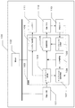
実施例1では図1のように前面センサ110による測色領域が有効画素領域120内にある例について説明する。前面センサ110は液晶パネル112の所定の測色領域に表示される画像を測色する。有効画素領域120とは画像表示装置100に入力される画像が表示される領域のことである。図2は本発明が適用される画像表示装置100の機能ブロック図である。画像表示装置100は画像入力部101、記憶部102、制御部103、バックライト111、液晶パネル112、前面センサ110で構成される。バックライト111は、独立に輝度を制御可能な複数の発光領域であるLD領域からなる照明手段である。液晶パネル112は、バックライト111により照明される表示パネルである。制御部103は、入力される画像に応じてバックライト111の発光領域毎に輝度を制御する。
In the first embodiment, an example in which the colorimetric region by the
画像入力部101は外部から不図示のDP(Display Port)やDVI(Digital Visual
Interface)等を通じて不図示のPC(パーソナルコンピュータ)等の画像出力装置からの画像信号を受け付ける部分である。記憶部102にはLD制御で使用しうるバックライト輝度(LD領域に設定可能なバックライト輝度)毎の画像処理パラメータが格納されており、制御部103によって読み書きされる。制御部103はローカルディミング制御部104、バックライト制御部105、画像処理部106、キャリブレーション進捗管理部
107、パッチ重畳部108、キャリブレーション計算部109で構成され、画像表示装置100全体を制御する。
The
Interface) is a part that receives an image signal from an image output device such as a PC (personal computer) (not shown). The
ローカルディミング制御部104は、画像入力部101から受け取った入力画像の統計量を取得し、統計量に基づいて各LD領域のバックライト輝度を決定し、バックライト制御部105に伝える。また、決定したバックライト輝度に対応する画像処理を行うように画像処理部106に伝える。
The local
バックライト制御部105は、ローカルディミング制御部104が決定した各LD領域のバックライト輝度と、隣接するLD領域からのバックライト光の漏れと、に基づき、各LD領域のバックライト111の発光量を決定し、バックライト111を制御する。
Based on the backlight luminance of each LD region determined by the local
画像処理部106は入力画像に対してLD領域毎にバックライト輝度に対応した画像処理パラメータを用いて画像処理を行い、液晶パネル112へ出力する。
The
キャリブレーション進捗管理部107はLD制御で使用しうるバックライト輝度毎にキャリブレーションパッチの測色の進捗管理表を保持している。キャリブレーション進捗管理部107は、決定されたバックライト輝度でのキャリブレーションにおけるパッチの測色の進捗を確認して、パッチ重畳部108に次に表示するパッチを指示する。
The calibration
パッチ重畳部108はキャリブレーション進捗管理部107から指示されたパッチ画像を前面センサ110の直下の入力画像に重畳する。
The
キャリブレーション計算部109は測定した輝度、色度に基づいて画像処理パラメータを計算する。
The
前面センサ110は液晶パネル112に表示された画像を測色する。実施例1では、前面センサ110による測色位置を含むLD領域は有効画素領域内にある。前面センサ110は、1回の測色を入力画像の1フレームの期間(以下1V期間)以内に行うことができ、複数回測定することで、測色精度を上げることができるセンサである。
The
画像処理部106について詳細に説明する。画像処理部106はバックライト輝度毎に少なくとも色域調整用のパラメータ、色温度調整用のパラメータ、γ調整用のパラメータ、輝度伸長用のパラメータをセットすることができる。
The
キャリブレーション進捗管理部107が保持するキャリブレーション進捗管理表について詳細に説明する。図3はキャリブレーション進捗管理表の一例である。所定のキャリブレーション対象のバックライト輝度毎に、「キャリブレーション済み」、「パッチ進捗度」、「現パッチ測色回数」「画像処理パラメータ」の項目がある。「キャリブレーション済み」の項目は、そのバックライト輝度でのキャリブレーションが完了しているか否かを示しており、0がキャリブレーションされていない、1がキャリブレーション済みを示している。「パッチ進捗度」の項目は、キャリブレーション済みでない場合にいくつ目のパッチ画像まで測色を終えているかを示している。「現パッチ測色回数」の項目は、あるパッチ画像の測色の途中の場合そのパッチの測色回数はいくつかを示している。「画像処理パラメータ」の項目は、そのバックライト輝度に対応する画像処理パラメータは、どのバックライト輝度での測色値をもとに作成されているかを示す。
The calibration progress management table held by the calibration
図3のキャリブレーション進捗管理表の例では、ユーザがキャリブレーションの目標白輝度を200cd/m2に設定し、LD制御で使用しうるバックライト輝度は50cd/m2、100cd/m2、150cd/m2、200cd/m2の4段階の場合である。
実施例1ではLD制御で使用しうる全てのバックライト輝度に対してキャリブレーションにより画像処理パラメータを求めていく。実施例1ではキャリブレーションのためのパッチ画像は全部で8個であるとする。従って、パッチ進捗度が8になったときにキャリブレーション済みとなる。最大輝度であるバックライト輝度200cd/m2では、8個のパッチ画像の測色が全て終わり、キャリブレーションが完了していることを示している。また、他のバックライト輝度ではまだまったく測色しておらず、バックライト輝度200cd/m2での測色結果から画像処理パラメータを作成していることを示している。
In the example of the calibration progress management table of FIG. 3, the user sets a target white brightness of
In the first embodiment, image processing parameters are obtained by calibration for all backlight luminances that can be used in LD control. In the first embodiment, it is assumed that there are eight patch images for calibration in total. Therefore, the calibration is completed when the patch progress degree becomes 8. The backlight luminance of 200 cd / m 2 that is the maximum luminance indicates that the color measurement of all eight patch images has been completed and the calibration has been completed. Further, it is shown that color measurement is not yet performed at other backlight luminances, and image processing parameters are created from the color measurement results at the backlight luminance of 200 cd / m 2 .
次に図4、図5、図6のフローチャートを用いて、各バックライト輝度に対応する画像処理パラメータの作成及び適用の処理の流れについて説明する。 Next, the flow of processing for creating and applying image processing parameters corresponding to each backlight luminance will be described using the flowcharts of FIGS. 4, 5, and 6.
全体の処理の流れは図4のフローチャートに従う。すなわち、制御部103は、バックライト輝度が目標白輝度に対応する画像処理パラメータをキャリブレーションにより作成し、他のバックライト輝度に関しては推測で求める。各LD領域の処理は図5のフローチャートに従う。すなわち、制御部103は、毎V期間、各LD領域のバックライト輝度に合わせて、各LED領域に適用する画像処理パラメータを切り替える。前面センサ110が配置されているLD領域の処理は図6のフローチャートに従う。すなわち、制御部103は、他のLD領域と同様にLD制御の動作を行いながら、キャリブレーションパッチを表示、測色し、推測で求めていた画像処理パラメータを、キャリブレーション結果に基づき作成した画像処理パラメータによって置き換えて行く。図6のフローチャートが本発明の特徴となる画面に影響を与えずに各バックライト輝度の画像処理パラメータを作成していく処理を示す。
The overall processing flow follows the flowchart of FIG. That is, the
図4のフローチャートについて説明する。図4のフローチャートの処理は一般的なキャリブレーションの処理と同様である。ユーザはまずキャリブレーションアプリケーションを立ち上げ目標色域、目標色温度、目標白輝度、目標γカーブ等を設定し、バックライト輝度が目標白輝度に対応するキャリブレーションを開始する。キャリブレーションを開始したところから図4のフローチャートは開始する。 The flowchart of FIG. 4 will be described. The process of the flowchart of FIG. 4 is the same as a general calibration process. The user first starts a calibration application, sets a target color gamut, target color temperature, target white luminance, target γ curve, and the like, and starts calibration in which the backlight luminance corresponds to the target white luminance. The flowchart of FIG. 4 starts from the point where calibration is started.
S101でバックライト制御部105は前面センサ110が配置されているLD領域のバックライト輝度が目標白輝度となるように、バックライト111の光量を調整する。
In S101, the
S102でパッチ重畳部108はキャリブレーションパッチ画像を画像に重畳し表示する。
In step S102, the
S103で前面センサ110はパッチ画像を測色する。ここでの測色は精度をよくするため、1パッチにつき5回測色する。これを全てのキャリブレーションパッチ画像の測色が終わるまで繰り返す。キャリブレーションパッチ画像は具体的には、例えば以下の画素値を持つ8個のパッチ画像である。
(R,G,B)=(255,0,0),(0,255,0),(0,0,255),(255,255,255),(0,0,0),(64,64,64),(128,128,128),(192,192,192)
In S103, the
(R, G, B) = (255, 0, 0), (0, 255, 0), (0, 0, 255), (255, 255, 255), (0, 0, 0), (64 , 64, 64), (128, 128, 128), (192, 192, 192)
S104にて全てのキャリブレーションパッチ画像を測色したかの判定がなされ、肯定判定された場合、S105でキャリブレーション計算部109は測色値をもとにバックライト輝度が目標白輝度に対応する画像処理パラメータを作成する。
In S104, it is determined whether all the calibration patch images have been colorimetrically measured. If the determination is affirmative, in S105, the
キャリブレーション計算部109は、(255,0,0),(0,255,0),(0,0,255),(255,255,255)のパッチの測色値をもとにパネルの色域を目標色域へと変換する色域補正用のパラメータを作成する。
The
キャリブレーション計算部109は、(255,255,255)の測色値をもとにパネルの色温度を目標色温度へと変換する色温度調整用のパラメータを作成する。
The
キャリブレーション計算部109は、(0,0,0),(64,64,64),(128,128,128),(192,192,192),(255,255,255)の測色値をもとにパネルのγを目標γへと変換するγ補正パラメータを作成する。
The
S106でキャリブレーション計算部109は上記の処理で測色結果に基づき作成した画像処理パラメータ(図3の例ではバックライト輝度200cd/m2での画像処理パラメータ)をもとに、他のバックライト輝度に対応する画像処理パラメータを作成する。具体的には色域、色温度、γ調整用パラメータは200cd/m2のパラメータと同一とする。また、画像処理パラメータ作成対象のバックライト輝度と実際に測色を行ったバックライト輝度(例えば200cd/m2)との差分を補うための輝度伸長パラメータをバックライト輝度と反比例する値とする。このようにしてキャリブレーション計算部109はLD制御により使用されうる全てのバックライト輝度に対応する画像処理パラメータを作成する。作成した画像処理パラメータは記憶部102に保存される。以上の処理が完了した後、ユーザがキャリブレーションアプリケーションを終了することにより、目標白輝度に対応するキャリブレーションが終了する。
In S106, the
次に、図5のフローチャートに即して、作成した画像処理パラメータの適用の仕方を説明する。図5のフローチャートの処理は一般的なLD制御と同様である。本フローチャートの処理は毎V期間、実行される。 Next, a method of applying the created image processing parameter will be described with reference to the flowchart of FIG. The process of the flowchart in FIG. 5 is the same as the general LD control. The process of this flowchart is executed every V period.
S201でローカルディミング制御部104は入力画像の統計量を取得し、各LD領域のバックライト輝度を決定する。
In S201, the local
S202でバックライト制御部105は、それぞれのLD領域のバックライト光量を決定し、バックライト111の光量を変更する。
In step S <b> 202, the
S203で画像処理部106はLD領域毎にそのLD領域のバックライト輝度に対応する画像処理パラメータを記憶部102から取得してその画像処理パラメータを用いて入力画像に画像処理を施す。
In S203, the
次に、通常使用中に、測色に基づき画像処理パラメータを作成済みのバックライト輝度(例えば200cd/m2)以外のバックライト輝度に対応する推測による画像処理パラメータを、測色に基づき作成した画像処理パラメータで置き換える処理を説明する。図6に即して説明する。他のバックライト輝度でのキャリブレーションでも200cd/m2でのキャリブレーションと同じく、以下の8個のパッチを測色するものとする。
(R,G,B)=(255,0,0),(0,255,0),(0,0,255),(255,255,255),(0,0,0),(64,64,64),(128,128,128),(192,192,192)
また、1パッチにつき5回の測色を行うものとする。図6のフローチャートの処理は毎V期間、実行される。S301〜S303は図5と同じでLD制御の処理である。
Next, during normal use, an image processing parameter was created based on the colorimetry based on the colorimetry based on the colorimetry based on the estimation of the backlight luminance (for example, 200 cd / m 2 ). Processing for replacement with image processing parameters will be described. This will be described with reference to FIG. In the calibration with other backlight luminance, the following eight patches are measured in the same manner as in the calibration at 200 cd / m 2 .
(R, G, B) = (255, 0, 0), (0, 255, 0), (0, 0, 255), (255, 255, 255), (0, 0, 0), (64 , 64, 64), (128, 128, 128), (192, 192, 192)
Further, it is assumed that the color measurement is performed five times per patch. The process of the flowchart of FIG. 6 is executed every V period. S301 to S303 are the same as FIG.
S304でキャリブレーション進捗管理部107は、前面センサ110が配置されているLD領域についてS302で決定されたバックライト輝度をキャリブレーション進捗管理表から検索し、キャリブレーションが完了しているかを確認する。完了していればこのフローチャートの処理は終了する。完了していなければ、S305でキャリブレーション進捗管理部107は、そのバックライト輝度での測色がどのパッチまで完了しているかを
確認し、次に測色するパッチを決定する。
In step S304, the calibration
S306でパッチ重畳部108は前面センサ110直下のLD領域に、S305で決定したパッチを重畳表示する。
In S306, the
S307で前面センサ110は表示されたパッチを測色する。
In step S <b> 307, the
S308でキャリブレーション進捗管理部107はS307でのパッチの測色によってキャリブレーション進捗管理表を更新し、そのパッチの測色回数が規定の回数(例えば5回)に達したかを判定する。
In step S308, the calibration
測色回数が5回に達していれば、S309で、キャリブレーション進捗管理部107は、前面センサ110が配置されているLD領域についてS302で決定されたバックライト輝度の全てのパッチを測色し終えたかを判定する。
If the number of colorimetry has reached 5, the calibration
全てのパッチを測定し終えた場合、S310でキャリブレーション計算部109は、このバックライト輝度に対応する画像処理パラメータを作成する。
When all the patches have been measured, the
S311でキャリブレーション計算部109は未キャリブレーションのバックライト輝度に対応する画像処理パラメータを作成しなおし、更新する。例えば、既にキャリブレーションされているバックライト輝度に対応するパラメータと今回キャリブレーションが完了したバックライト輝度に対応するパラメータとに基づく線形補間計算により、その間にあるバックライト輝度に対応するパラメータを求める。キャリブレーション計算部109は、作成した画像処理パラメータを記憶部102に保存し、次のV期間からLD制御に適用する。
In S311, the
図7はパラメータが決定していく様子を表した図である。一番上の時間軸の1目盛りが1V期間であり、時間軸の右向きが正の方向である。最初のV期間では前面センサ110が配置されているLD領域のバックライト輝度は50cd/m2であり、バックライト輝度50cd/m2でのキャリブレーションで測色するパッチ画像はパッチ1である。このV期間では前面センサ110が配置されているLD領域にパッチ1を表示し測色する。各パッチ5回ずつ測色し、パッチ1〜8の全てについてバックライト輝度50cd/m2での測色が完了した時点で、50cd/m2での画像処理パラメータを作成する。また、既にキャリブレーションを終えている200cd/m2と今回完了した50cd/m2以外のバックライト輝度のパラメータを200cd/m2での画像処理パラメータと50cd/m2での画像処理パラメータから再算出(推定計算)し、更新する。そして、次のV期間から更新後の画像処理パラメータをLD制御に適用する。
FIG. 7 is a diagram showing how parameters are determined. One scale on the top time axis is a 1V period, and the right direction of the time axis is a positive direction. In the first V period, the backlight luminance of the LD region where the
このようにすることでキャリブレーションにより画面に影響する期間はバックライト輝度が目標白輝度で行う1回分だけとなる。そして、画面に影響を与えない状態で他のバックライト輝度に対応する画像処理パラメータをキャリブレーションすることができ、LD制御の各バックライト輝度での精度を高めることができる。 By doing so, the period in which the screen affects the calibration is only one time when the backlight luminance is set to the target white luminance. Then, it is possible to calibrate image processing parameters corresponding to other backlight luminances without affecting the screen, and it is possible to improve the accuracy of each backlight luminance of LD control.
尚、画像処理パラメータの作成の際に測色するパッチは上記の説明に用いたものに限らない。また、キャリブレーション計算部109は全てのパッチの測色が終わった後に全ての画像処理パラメータの作成を行うものとして説明した。しかし、測色するたびに順次、色域補正パラメータや色温度調整用パラメータを作成していき、作成した画像処理パラメータを反映して次の画像処理パラメータを測定してもよい。
It should be noted that the colorimetric patches used when creating the image processing parameters are not limited to those used in the above description. Further, it has been described that the
また、図5のフローチャートは毎V期間行う、つまりLD制御によるバックライトの変
更を毎V期間行うとして説明したが、これに限らず、数V期間毎に変更してもよい。その場合、図6のフローチャートの処理も数V期間毎に行う。S307での測色は次のバックライト輝度の変化までに時間があれば1回に限らず複数回取得してもよい。例えば、バックライト輝度の更新が数V期間毎に行われる場合、当該数V期間の間に複数回測色値の取得を行うようにしても良い。これにより規定回数(5回)の測色が短時間で完了する。
Further, the flowchart of FIG. 5 has been described as performing every V period, that is, changing the backlight by LD control every V period. However, the present invention is not limited to this, and may be changed every several V periods. In that case, the process of the flowchart of FIG. 6 is also performed every several V periods. The color measurement in S307 may be acquired not only once but also multiple times if there is time until the next change in backlight luminance. For example, when the backlight luminance is updated every several V periods, the colorimetric values may be acquired a plurality of times during the several V periods. Thereby, the specified number of times (5 times) of color measurement is completed in a short time.
また、S310及びS311で作成した画像処理パラメータの反映は次のV期間からとしたが、例えば静止画を表示していた場合等に途中から色が変わると違和感を与える可能性があるため、更新された画像処理パラメータの適用タイミングは上記の例に限らない。例えば、画像表示装置100の電源を一度切って再び電源を入れたタイミングや、画像のシーンチェンジを検出してそのタイミングで、更新された画像処理パラメータを適用するようにしてもよい。
In addition, the reflection of the image processing parameters created in S310 and S311 is performed from the next V period. However, for example, when a still image is displayed, there is a possibility that the color changes from the middle. The application timing of the processed image processing parameters is not limited to the above example. For example, the updated image processing parameters may be applied at the timing when the
また、キャリブレーションが一度完了したバックライト輝度については再びキャリブレーションしないものとして説明したが、キャリブレーションが一度完了したバックライト輝度について再びキャリブレーションを行い、画像処理パラメータを更新してもよい。 In addition, although it has been described that the backlight luminance once calibrated is not calibrated again, calibration may be performed again for the backlight luminance once calibrated, and the image processing parameters may be updated.
また、バックライト輝度が目標白輝度でのキャリブレーションとその他のバックライト輝度でのキャリブレーションで同一のパッチ群を測色するものとして説明したが、これに限らず、その他のバックライト輝度のキャリブレーションではパッチ数を減らしてもよい。1パッチの測色回数についても全パッチ同一で5回測色するとしたが、精度を高めるために、輝度の低いパッチほど多く、輝度の高いパッチほど少ない回数としてもよい。 In addition, although it has been described that the same patch group is measured by the calibration with the backlight brightness of the target white brightness and the calibration with the other backlight brightness, the invention is not limited to this, but the calibration of other backlight brightness is performed. The number of patches may be reduced in the event. The number of times of color measurement for one patch is the same for all patches, and the color measurement is performed five times. However, in order to improve accuracy, the number of patches with lower luminance may be higher and the number of patches with higher luminance may be lower.
(実施例2)
実施例2では図8のように前面センサ110が有効画素領域外にある例について説明する。実施例2では実施例1との違いを中心に説明する。前面センサ110はベゼル113の内側に有り外からは見えない。液晶パネル及びバックライトは前面センサの直下にも存在するが、やはりベゼル113の外側からは見えないため、前面センサ110の直下のバックライト輝度が変化してもユーザには見えない。したがって、実施例1よりは自由に前面センサ110が配置されているLD領域のバックライト輝度を変更してキャリブレーションが可能である。
(Example 2)
In the second embodiment, an example in which the
しかし、前面センサ110の直下のバックライト及び液晶パネルは、有効画素領域部分120に隣接しているため、隣接するLD領域に当該バックライトの光が漏れる。そのため隣接LD領域のバックライト輝度が低いときに前面センサ110が配置されたLD領域を高いバックライト輝度にすると光漏れにより隣接LD領域の輝度を十分に下げられなくなってしまう。つまり、前面センサ110が配置されているLD領域のバックライト輝度によっては隣のLD領域のバックライト輝度を入力画像から決まるバックライト輝度に合わせられない場合がある。実施例2はこの点を考慮した実施例である。
However, since the backlight and the liquid crystal panel directly under the
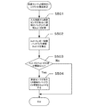
前面センサ110が配置されているLD領域のバックライト輝度の決め方を図9のフローチャートに即して説明する。
A method of determining the backlight luminance of the LD region where the
S401でローカルディミング制御部104は入力画像の統計量を取得し、統計量に基づき、前面センサ110が配置されているLD領域に隣接するLD領域のバックライト輝度(以下隣接BL輝度と呼ぶ)を算出する。
In S401, the local
S402でローカルディミング制御部104は、LD制御で使用するバックライト輝度のうち隣接BL輝度に近いバックライト輝度Bcd/m2を求める。
In S402, the local
S403でキャリブレーション進捗管理部107は、S402求めたバックライト輝度Bcd/m2でのキャリブレーションが完了しているかを確認する。完了していれば、キャリブレーション進捗管理部107は、S402に戻り、LD制御で使用するバックライト輝度のうち次に隣接BL輝度に近いバックライト輝度を求める。
In S403, the calibration
完了していれば、S404でローカルディミング制御部104は前面センサが配置されているLD領域のバックライト輝度をS402で求めたバックライト輝度Bcd/m2とした場合に、隣接するLD領域のバックライト輝度を隣接BL輝度に維持できるかを確認する。例えば、隣接BL輝度とバックライト輝度Bcd/m2との差分が閾値以内である場合に、隣接するLD領域のバックライト輝度を隣接BL輝度に維持できると判断するようにすればよい。隣接するLD領域のバックライト輝度を隣接BL輝度に維持できなければ、このフローチャートを開始したV期間では前面センサでの測色は行わないものとする(S406)。
If completed, in S404, the local
隣接するLD領域のバックライト輝度を隣接BL輝度に維持できるのであればS405でローカルディミング制御部104は前面センサの配置されているLD領域のバックライト輝度をS402で求めたバックライト輝度Bcd/m2に決定する。
If the backlight luminance of the adjacent LD region can be maintained at the adjacent BL luminance, in S405, the local
このようにすることで、実施例1よりも自由に前面センサ110が配置されているLD領域のバックライト輝度を変更してキャリブレーションを行うことができ、また、キャリブレーションの実行が画面に影響を与えることを抑制できる。よってLD制御で使用しうるバックライト輝度に対応する画像処理パラメータをキャリブレーションにより精度の良い値にすることができる。
In this way, the calibration can be performed by changing the backlight luminance of the LD region where the
(実施例3)
実施例3では実施例1と同じく前面センサ110が有効画素領域内にあり、LD制御で使用するバックライト輝度の段階が実施例1より多数である例について説明する。実施例3では実施例1との違いを中心に説明する。LD制御で使用するバックライト輝度の段階数が多い場合、実施例1のように処理すると、LD制御で使用する全てのバックライト輝度についてキャリブレーションが完了するまでに非常に長い時間がかかる可能性がある。また、全てのバックライト輝度に対応する画像処理パラメータを保持するために記憶部102に大きな記憶容量を必要とする。
(Example 3)
In the third embodiment, an example will be described in which the
そこで実施例3では、キャリブレーションを行って測色結果に基づき画像処理パラメータを作成する対象となるバックライト輝度の数を制限する。キャリブレーションの対象となるバックライト輝度を制限バックライト輝度と呼ぶ。制限バックライト輝度は例えば、20cd/m2毎に20cd/m2、40cd/m2、60cd/m2、…と設定する。制限バックライト輝度以外のバックライト輝度の画像処理パラメータは、制限バックライト輝度の画像処理パラメータに基づく補間により求める。 In the third embodiment, therefore, the number of backlight luminances to be subjected to calibration and to create image processing parameters based on the color measurement results is limited. The backlight luminance to be calibrated is called limited backlight luminance. Limiting the backlight luminance, for example, 20 cd for each 20cd / m 2 / m 2, 40cd / m 2, 60cd / m 2, to set and so on. Image processing parameters for backlight luminance other than the limited backlight luminance are obtained by interpolation based on the image processing parameters for limited backlight luminance.
実施例3のLD制御は図5とほぼ同じである。S203での画像処理パラメータを変更するときに、S201で求めたバックライト輝度が制限バックライト輝度である場合、画像処理部106は、記憶部102からそのバックライト輝度に対応する画像処理パラメータを取得して変更する。S201で求めたバックライト輝度が制限バックライト輝度でない場合、画像処理部106は、当該バックライト輝度に上下最も近い制限バックライト輝度に対応する画像処理パラメータを記憶部102から取得する。そして、それぞれの画像処理パラメータに基づく線形補間により、S201で求めたバックライト輝度に対応する画像処理パラメータを求めて、画像処理に適用する。
The LD control in the third embodiment is almost the same as in FIG. When changing the image processing parameter in S203, if the backlight luminance obtained in S201 is the limited backlight luminance, the
前面センサ110が配置されているLD領域のバックライト輝度の決め方を図11に即
して説明する。S501でローカルディミング制御部104は入力画像の統計量を取得し、前面センサ110が配置されているLD領域のバックライト輝度Acd/m2を算出する。
A method for determining the backlight luminance of the LD region in which the
S502でローカルディミング制御部104はS501で算出したバックライト輝度Acd/m2と近い制限バックライト輝度Bcd/m2を求め、S503でその差が閾値以下であるかを判定する。
In step S502, the local
閾値以下であればS504でバックライト制御部105は、前面センサ110が配置されているLD領域のバックライト輝度を制限バックライト輝度Bcd/m2とする。その後の動作は図6のS302以降と同じである。閾値より大きい場合はそのV期間に関してはパッチの測色を行わない。
If it is equal to or less than the threshold value, the
図10は、画像の統計量に基づき算出されたバックライト輝度と最も近い制限バックライト輝度との差の閾値が1cd/m2である場合に、前面センサ110が配置されているLD領域のバックライト輝度の変更の仕方を示した図である。図10では、制限バックライト輝度は20cd/m2毎である。
FIG. 10 shows the LD region in which the
実施例3によれば、画像への影響を抑制しつつ制限バックライト輝度の画像処理パラメータのキャリブレーションを行うことができる。制限バックライト輝度以外のバックライト輝度については線形補間により求めるので、LD制御に使用する全てのバックライト輝度の画像処理パラメータの作成に要する時間が過剰に長くなることを抑制でき、必要メモリ容量を抑えることができる。 According to the third embodiment, it is possible to calibrate the image processing parameter of the limited backlight luminance while suppressing the influence on the image. Since the backlight brightness other than the limited backlight brightness is obtained by linear interpolation, it is possible to suppress the time required to create image processing parameters for all backlight brightness used for LD control from being excessively long, and to reduce the necessary memory capacity. Can be suppressed.
100 画像表示装置
110 前面センサ
120 有効画素領域
100
Claims (21)
前記照明手段により照明される表示パネルと、
入力される画像に基づいて前記発光領域毎に輝度を制御する制御手段と、
前記表示パネルの所定の測色領域に表示される画像を測色する測色手段と、
前記発光領域に設定可能な複数の輝度について輝度毎に前記測色手段による測色結果に基づいてキャリブレーションを行うキャリブレーション手段と、
を備え、
前記キャリブレーション手段は、前記制御手段が前記測色領域に対応する発光領域に設定した輝度との差分が閾値以下である輝度についてキャリブレーションを行うことを特徴とするキャリブレーション装置。 Illumination means consisting of a plurality of light emitting areas whose brightness can be controlled independently;
A display panel illuminated by the illumination means;
Control means for controlling the luminance for each of the light emitting areas based on an input image;
Colorimetric means for colorimetrically measuring an image displayed in a predetermined colorimetric region of the display panel;
Calibration means for performing calibration based on a colorimetric result by the colorimetric means for each luminance for a plurality of luminances that can be set in the light emitting area;
With
The calibration device, wherein the calibration unit performs calibration for a luminance whose difference from a luminance set in a light emitting region corresponding to the colorimetric region is equal to or less than a threshold value.
前記測色領域に対応する発光領域は、前記測色領域の直下の発光領域である請求項1〜5のいずれか1項に記載のキャリブレーション装置。 The colorimetric region is in an effective pixel region where an input image is displayed on the display panel,
The calibration device according to claim 1, wherein the light emission area corresponding to the color measurement area is a light emission area immediately below the color measurement area.
前記測色領域に対応する発光領域は、前記測色領域の直下の発光領域に隣接する有効画素領域内の発光領域である請求項1〜5のいずれか1項に記載のキャリブレーション装置。 The colorimetric region is outside the effective pixel region where an input image is displayed on the display panel,
The calibration device according to claim 1, wherein the light emission area corresponding to the color measurement area is a light emission area in an effective pixel area adjacent to a light emission area immediately below the color measurement area.
前記キャリブレーション手段は、キャリブレーション対象の輝度についてのキャリブレーション結果に基づき当該キャリブレーション対象の輝度に対応する前記画像処理のパラメータを設定する請求項1〜7のいずれか1項に記載のキャリブレーション装置。 Image processing means for performing image processing according to the luminance of each light emitting area on the image corresponding to each light emitting area;
The calibration according to any one of claims 1 to 7, wherein the calibration unit sets the image processing parameter corresponding to the luminance of the calibration target based on a calibration result of the luminance of the calibration target. apparatus.
像処理のパラメータを、キャリブレーション結果が得られている輝度に対応する前記画像処理のパラメータに基づく補間計算により設定する請求項1〜8のいずれか1項に記載のキャリブレーション装置。 The image processing means sets the image processing parameter corresponding to the luminance for which the calibration result is not obtained by interpolation calculation based on the image processing parameter corresponding to the luminance for which the calibration result is obtained. Item 9. The calibration device according to any one of Items 1 to 8.
前記照明手段により照明される表示パネルと、
を備える画像表示装置のキャリブレーション装置の制御方法であって、
入力される画像に基づいて前記発光領域毎に輝度を制御する制御工程と、
前記表示パネルの所定の測色領域に表示される画像を測色する測色工程と、
前記発光領域に設定可能な複数の輝度について輝度毎に前記測色工程による測色結果に基づいてキャリブレーションを行うキャリブレーション工程と、
を有し、
前記キャリブレーション工程では、前記制御工程で前記測色領域に対応する発光領域に設定された輝度との差分が閾値以下である輝度についてキャリブレーションを行うことを特徴とするキャリブレーション装置の制御方法。 Illumination means consisting of a plurality of light emitting areas whose brightness can be controlled independently;
A display panel illuminated by the illumination means;
A control method for a calibration device of an image display device comprising:
A control step of controlling the luminance for each light emitting area based on an input image;
A colorimetric step of measuring the color of an image displayed in a predetermined colorimetric region of the display panel;
A calibration step for performing calibration based on the color measurement result of the color measurement step for each of a plurality of luminances that can be set in the light emitting region;
Have
In the calibration step, calibration is performed for luminance whose difference from the luminance set in the light emission region corresponding to the colorimetric region in the control step is equal to or less than a threshold value.
前記測色領域に対応する発光領域は、前記測色領域の直下の発光領域である請求項11〜15のいずれか1項に記載のキャリブレーション装置の制御方法。 The colorimetric region is in an effective pixel region where an input image is displayed on the display panel,
The method for controlling a calibration device according to claim 11, wherein the light emission area corresponding to the color measurement area is a light emission area immediately below the color measurement area.
前記測色領域に対応する発光領域は、前記測色領域の直下の発光領域に隣接する有効画素領域内の発光領域である請求項11〜15のいずれか1項に記載のキャリブレーション
装置の制御方法。 The colorimetric region is outside the effective pixel region where an input image is displayed on the display panel,
The control of the calibration apparatus according to claim 11, wherein the light emission area corresponding to the color measurement area is a light emission area in an effective pixel area adjacent to the light emission area immediately below the color measurement area. Method.
前記キャリブレーション工程では、キャリブレーション対象の輝度についてのキャリブレーション結果に基づき当該キャリブレーション対象の輝度に対応する前記画像処理のパラメータを設定する請求項11〜17のいずれか1項に記載のキャリブレーション装置の制御方法。 An image processing step of performing image processing according to the luminance of each light emitting area on the image corresponding to each light emitting area;
The calibration according to any one of claims 11 to 17, wherein in the calibration step, a parameter of the image processing corresponding to the luminance of the calibration target is set based on a calibration result of the luminance of the calibration target. Control method of the device.
Priority Applications (1)
| Application Number | Priority Date | Filing Date | Title |
|---|---|---|---|
| JP2013034552A JP2014164090A (en) | 2013-02-25 | 2013-02-25 | Calibration device and control method thereof |
Applications Claiming Priority (1)
| Application Number | Priority Date | Filing Date | Title |
|---|---|---|---|
| JP2013034552A JP2014164090A (en) | 2013-02-25 | 2013-02-25 | Calibration device and control method thereof |
Publications (1)
| Publication Number | Publication Date |
|---|---|
| JP2014164090A true JP2014164090A (en) | 2014-09-08 |
Family
ID=51614745
Family Applications (1)
| Application Number | Title | Priority Date | Filing Date |
|---|---|---|---|
| JP2013034552A Pending JP2014164090A (en) | 2013-02-25 | 2013-02-25 | Calibration device and control method thereof |
Country Status (1)
| Country | Link |
|---|---|
| JP (1) | JP2014164090A (en) |
Cited By (1)
| Publication number | Priority date | Publication date | Assignee | Title |
|---|---|---|---|---|
| JP2015028606A (en) * | 2013-06-28 | 2015-02-12 | キヤノン株式会社 | Image display device and control method thereof |
-
2013
- 2013-02-25 JP JP2013034552A patent/JP2014164090A/en active Pending
Cited By (1)
| Publication number | Priority date | Publication date | Assignee | Title |
|---|---|---|---|---|
| JP2015028606A (en) * | 2013-06-28 | 2015-02-12 | キヤノン株式会社 | Image display device and control method thereof |
Similar Documents
| Publication | Publication Date | Title |
|---|---|---|
| JP5121647B2 (en) | Image display apparatus and method | |
| KR20150139014A (en) | Methods of correcting gamma and display device employing the same | |
| JP4864076B2 (en) | Backlight brightness control device and video display device | |
| US20130155125A1 (en) | Display apparatus and control method thereof | |
| JP2009204825A (en) | Display | |
| US20120218175A1 (en) | Image display apparatus and control method therefor | |
| TWI576817B (en) | Display with Automatic Image Optimizing function and Related Image Adjusting Method | |
| US20160267834A1 (en) | Display diode relative age | |
| JP2019040036A (en) | Electronic apparatus, display, and display control method | |
| KR20170049241A (en) | Display device and method for driving the same | |
| JPWO2011036692A1 (en) | Image processing apparatus and image display apparatus | |
| JP5800946B2 (en) | Image display apparatus and control method thereof | |
| JP5371630B2 (en) | Display device | |
| JP5984401B2 (en) | Image display apparatus, control method therefor, and image display system | |
| JP2007322942A (en) | Backlight driving device, display device, and backlight driving method | |
| JP2015232689A (en) | Image display device and method for controlling the same | |
| JP5893673B2 (en) | Image display apparatus and control method thereof | |
| JP2011085911A (en) | Liquid crystal display and driving method thereof | |
| JP2014164090A (en) | Calibration device and control method thereof | |
| JP2009048131A (en) | Liquid crystal display device | |
| KR20230168210A (en) | Compensation method, compensation device, display device, and storage medium for display panel | |
| KR20080043118A (en) | Apparetus and method for compensating display color tonen for adjusted time of light source | |
| CN107784991B (en) | Automatic imaging correction method | |
| JP2018010129A (en) | Display device and method for controlling the same | |
| CN111816106A (en) | Display control method, device and computer readable storage medium |