JP2014161813A - Operation method of methane fermentation tank - Google Patents
Operation method of methane fermentation tank Download PDFInfo
- Publication number
- JP2014161813A JP2014161813A JP2013036201A JP2013036201A JP2014161813A JP 2014161813 A JP2014161813 A JP 2014161813A JP 2013036201 A JP2013036201 A JP 2013036201A JP 2013036201 A JP2013036201 A JP 2013036201A JP 2014161813 A JP2014161813 A JP 2014161813A
- Authority
- JP
- Japan
- Prior art keywords
- fermentation tank
- methane fermentation
- methane
- deposit
- liquid
- Prior art date
- Legal status (The legal status is an assumption and is not a legal conclusion. Google has not performed a legal analysis and makes no representation as to the accuracy of the status listed.)
- Granted
Links
- VNWKTOKETHGBQD-UHFFFAOYSA-N methane Chemical compound C VNWKTOKETHGBQD-UHFFFAOYSA-N 0.000 title claims abstract description 264
- 238000000855 fermentation Methods 0.000 title claims abstract description 109
- 230000004151 fermentation Effects 0.000 title claims abstract description 109
- 238000000034 method Methods 0.000 title claims abstract description 25
- 239000013049 sediment Substances 0.000 claims abstract description 38
- 239000007788 liquid Substances 0.000 claims description 71
- 238000003756 stirring Methods 0.000 claims description 62
- 238000000605 extraction Methods 0.000 claims description 43
- 238000012546 transfer Methods 0.000 claims description 18
- XLYOFNOQVPJJNP-UHFFFAOYSA-N water Substances O XLYOFNOQVPJJNP-UHFFFAOYSA-N 0.000 claims description 10
- 238000011017 operating method Methods 0.000 claims description 2
- 238000000151 deposition Methods 0.000 abstract 1
- 230000029087 digestion Effects 0.000 description 23
- 230000001079 digestive effect Effects 0.000 description 12
- 239000010802 sludge Substances 0.000 description 7
- 235000011389 fruit/vegetable juice Nutrition 0.000 description 6
- 239000007787 solid Substances 0.000 description 6
- 239000000126 substance Substances 0.000 description 6
- 238000010586 diagram Methods 0.000 description 5
- 241000894006 Bacteria Species 0.000 description 4
- 229910000831 Steel Inorganic materials 0.000 description 4
- 239000012530 fluid Substances 0.000 description 4
- 238000010438 heat treatment Methods 0.000 description 4
- 239000000463 material Substances 0.000 description 4
- 238000012545 processing Methods 0.000 description 4
- 239000002002 slurry Substances 0.000 description 4
- 239000010959 steel Substances 0.000 description 4
- 239000002351 wastewater Substances 0.000 description 4
- 230000008021 deposition Effects 0.000 description 3
- 239000000523 sample Substances 0.000 description 3
- 239000010865 sewage Substances 0.000 description 3
- 238000001514 detection method Methods 0.000 description 2
- 239000010794 food waste Substances 0.000 description 2
- 244000005700 microbiome Species 0.000 description 2
- 239000005416 organic matter Substances 0.000 description 2
- 239000000047 product Substances 0.000 description 2
- 239000004576 sand Substances 0.000 description 2
- 239000010801 sewage sludge Substances 0.000 description 2
- 238000005406 washing Methods 0.000 description 2
- 239000002028 Biomass Substances 0.000 description 1
- 241000270666 Testudines Species 0.000 description 1
- 239000006227 byproduct Substances 0.000 description 1
- 238000004140 cleaning Methods 0.000 description 1
- 238000010276 construction Methods 0.000 description 1
- 230000000694 effects Effects 0.000 description 1
- 238000002474 experimental method Methods 0.000 description 1
- 210000003608 fece Anatomy 0.000 description 1
- 239000002921 fermentation waste Substances 0.000 description 1
- 239000000706 filtrate Substances 0.000 description 1
- 230000005484 gravity Effects 0.000 description 1
- 238000009434 installation Methods 0.000 description 1
- 244000144972 livestock Species 0.000 description 1
- 239000010871 livestock manure Substances 0.000 description 1
- 238000005259 measurement Methods 0.000 description 1
- 239000002184 metal Substances 0.000 description 1
- 238000002156 mixing Methods 0.000 description 1
- 239000010815 organic waste Substances 0.000 description 1
- 229920003023 plastic Polymers 0.000 description 1
- 238000010298 pulverizing process Methods 0.000 description 1
- 238000004062 sedimentation Methods 0.000 description 1
- 239000002689 soil Substances 0.000 description 1
- 230000000087 stabilizing effect Effects 0.000 description 1
- 230000001360 synchronised effect Effects 0.000 description 1
- 125000000391 vinyl group Chemical group [H]C([*])=C([H])[H] 0.000 description 1
- 229920002554 vinyl polymer Polymers 0.000 description 1
- 238000004065 wastewater treatment Methods 0.000 description 1
Images


Classifications
-
- Y—GENERAL TAGGING OF NEW TECHNOLOGICAL DEVELOPMENTS; GENERAL TAGGING OF CROSS-SECTIONAL TECHNOLOGIES SPANNING OVER SEVERAL SECTIONS OF THE IPC; TECHNICAL SUBJECTS COVERED BY FORMER USPC CROSS-REFERENCE ART COLLECTIONS [XRACs] AND DIGESTS
- Y02—TECHNOLOGIES OR APPLICATIONS FOR MITIGATION OR ADAPTATION AGAINST CLIMATE CHANGE
- Y02E—REDUCTION OF GREENHOUSE GAS [GHG] EMISSIONS, RELATED TO ENERGY GENERATION, TRANSMISSION OR DISTRIBUTION
- Y02E50/00—Technologies for the production of fuel of non-fossil origin
- Y02E50/30—Fuel from waste, e.g. synthetic alcohol or diesel
Abstract
Description
本発明は、略水平な底面を有し、槽中心部にスクリュー式又はインペラ式の撹拌装置が設けられているメタン発酵槽の運転方法であって、底面に堆積する堆積物の除去が可能な運転方法に関する。 The present invention is a method for operating a methane fermentation tank having a substantially horizontal bottom surface and a screw-type or impeller-type stirring device provided at the center of the tank, and can remove sediment deposited on the bottom surface. It relates to the driving method.
下水汚泥のような有機物を含有する廃水の処理方法には、汚泥の安定化及びメタンガスの回収を目的として、嫌気性消化法が一般的に用いられる。嫌気性消化法としては、有機物を含有する廃水をメタン発酵槽(消化槽)に投入し、嫌気性下でメタン菌により発酵処理することで、有機物をメタンガスに転換するメタン発酵法が汎用される。投入原料の性状及び運転条件によって、様々な処理方法及びメタン発酵槽が提案されている。 An anaerobic digestion method is generally used as a method for treating wastewater containing organic substances such as sewage sludge for the purpose of stabilizing sludge and recovering methane gas. As anaerobic digestion method, wastewater containing organic substances is put into a methane fermentation tank (digestion tank) and fermented with methane bacteria under anaerobic conditions, so that the methane fermentation process that converts organic substances into methane gas is widely used. . Various treatment methods and methane fermenters have been proposed depending on the properties of the input materials and the operating conditions.
嫌気性下でメタン菌により有機物が嫌気的に生分解されると、バイオガスと水とに分解される。このような嫌気性消化法は、廃水に含有されている有機物を大幅に減少することができると共に、副産物として生成するメタンガス(バイオガス)をエネルギーとして回収できる利点がある。 When an organic substance is anaerobically biodegraded by methane bacteria under anaerobic conditions, it is decomposed into biogas and water. Such an anaerobic digestion method has the advantage that the organic matter contained in the wastewater can be greatly reduced and methane gas (biogas) produced as a by-product can be recovered as energy.
廃水中には難分解性で比重の高い固形物又は発酵不適物(砂、毛髪、ビニール片等)も存在することから、メタン発酵槽内にこれらが徐々に堆積する。そのため、定期的にメタン発酵槽底面に堆積した堆積物を除去する必要がある。特許文献1は、メタン菌を主体とする嫌気性微生物を担持させたろ床を有する第1発酵槽と第2発酵槽を直列に配置してメタン発酵槽とし、この第1発酵槽に有機性廃棄物を粉砕したスラリーを投入し、第1発酵槽のろ床を通過させてメタン発酵させた後の液状の処理液を第2発酵槽に送り、該処理液を第2発酵槽で再度メタン発酵させて、バイオガス等の資源を回収すると共に、発酵廃液を消化液として取出すメタン発酵処理方法において、前記第1発酵槽にガス撹拌装置を設けて、前記スラリーの投入時から所定時間経過するまでの間、前記ガス撹拌装置の出力を停止するか、又は出力を弱めて、該スラリー中の発酵不適物を沈降させて分離した後、前記ガス撹拌装置の出力を高めて、前記スラリーを撹拌しながら発酵させることを特徴とするメタン発酵処理方法を開示している。
In the wastewater, there are solids or fermentation unsuitables (sand, hair, vinyl pieces, etc.) that are hardly decomposable and have a high specific gravity, so these gradually accumulate in the methane fermentation tank. For this reason, it is necessary to periodically remove sediment deposited on the bottom surface of the methane fermentation tank. In
特許文献1に開示されているメタン発酵処理方法は、第1発酵槽において、処理液中に含まれている発酵処理が可能な成分と発酵不適物とを、沈降速度の差を利用することで効果的に分離できるため、発酵不適物の処理が容易となり、配管中にこれらが堆積して閉塞するといった事態を防止でき、メタン発酵処理を長期間安定して実施し得るとされている。また、第2発酵槽では、固形物が少なく、発酵不適物の極めて少ない液状の処理液が送られてくるので、第2発酵槽では高速処理が可能となる。そのため、全体として高速高容積負荷のメタン発酵処理を行い得るとされている。
The methane fermentation treatment method disclosed in
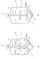
底面に堆積した堆積物の排出を可能にするため、特許文献1に示されるように、メタン発酵槽の底面は下方に凸な形状とし、最も低い位置に堆積物を抜き出すために配管を配置することが一般的である。また、一般的に下水汚泥の消化処理のために下水処理場に設けられるメタン発酵槽はコンクリート製で卵形又は亀甲形の形状となっており、この場合もメタン発酵槽の底面は下方に凸となっている。これは被処理液を撹拌するためにスクリュー式又はインペラ式の撹拌装置がメタン発酵槽に設けられる場合が多いが、卵形の形状の場合も、メタン発酵槽の底面が下方に凸となっている方が、デッドスペースが無く、被処理液の撹拌効率が高く好ましいとされている。スクリュー式又はインペラ式の撹拌装置を回転させた場合、被処理液の流れは、図5(a)に示される向きとなる。
In order to allow the sediment deposited on the bottom surface to be discharged, as shown in
嫌気性消化処理は、例えば、低温発酵においては温度20℃付近で滞留時間30〜60日、中温発酵においては温度37℃付近で滞留時間20〜30日で運転され、高温発酵においては温度55℃付近で滞留時間7〜20日程度で運転される。このため、このようなメタン発酵槽においては、図5(b)に示されるように、メタン発酵槽下部の凸部に堆積物14が溜まる。そこで当該凸部に堆積物引き抜き管16を設置することで、ある程度堆積物14を引き抜くことは可能である。しかし、図6に示されるように、堆積物引き抜き管16周辺の堆積物14は除去できるが、それ以外の堆積物14は引き抜くことが困難である。その結果、メタン発酵槽11下部の堆積物14量が徐々に増加し、メタン発酵槽11内にデッドスペースが増加するという問題がある。
Anaerobic digestion is operated, for example, at a temperature of about 20 ° C. for a low temperature fermentation at a residence time of 30 to 60 days, for a medium temperature fermentation at a temperature of about 37 ° C. for a residence time of 20 to 30 days, and for a high temperature fermentation at a temperature of 55 ° C. It is operated at a residence time of around 7 to 20 days. For this reason, in such a methane fermentation tank, as shown in FIG. 5 (b), the
一方で、近年、コンクリート製のメタン発酵槽の代替として、より容易に設置できる鋼板製のメタン発酵槽の要望が増加している。しかし、鋼板製のメタン発酵槽においては、施工の容易さから底面の形状を下方に向かって凸状とせずに、略平面状と形成することが望まれている。このようなメタン発酵槽において、図1(a)に示されるようにメタン発酵槽1を連続運転すると、図1(b)に示されるように、堆積物4がメタン発酵槽1の側面下部を中心に堆積されることが判明した。この場合、堆積物引き抜き管6をメタン発酵槽の底面7中央に設置し、ポンプPによって堆積物4を引き抜こうとしても、引き抜き管6周辺の堆積物のみが引き抜かれるだけであるため、堆積物を効率よく引く抜くことができない。
On the other hand, in recent years, as an alternative to a concrete methane fermentation tank, there has been an increasing demand for a steel plate methane fermentation tank that can be installed more easily. However, in a methane fermentation tank made of a steel plate, it is desired that the bottom surface is formed in a substantially flat shape without being convex downward from the viewpoint of ease of construction. In such a methane fermenter, when the
また、メタン発酵槽1の側面下部には消化液移送管8も設けられているが、消化液移送管8から堆積物4をポンプによって引き抜こうとしても、消化液移送管8の周辺の堆積物4のみが引き抜かれるだけであり、堆積物4を効率良く引き抜くことはできない。
Moreover, although the digestion
被処理液の供給を止め、メタン発酵槽1内の被処理液2をすべて排出すれば、メタン発酵槽1内を洗浄することにより、堆積物4を堆積物引き抜き管6から排出することは可能である。しかし、メタン発酵槽1の規模が大きいと、被処理液2の排出及びメタン発酵槽1内の洗浄に時間がかかり、長期間、運転を停止しなければならなくなる。また、規模が大きいメタン発酵槽においては、予備のメタン発酵槽を設けることができず、微生物により発酵処理の起ち上げにも時間を要する。このため、メタン発酵槽1内の被処理液2を排出するような洗浄方法は、現実的ではない。
If the supply of the liquid to be processed is stopped and all the
そこで本発明は、メタン発酵槽の底面に堆積する堆積物を、連続運転しながら効率よくメタン発酵槽外へと除去し得るメタン発酵槽の運転方法の提供を目的とする。 Then, this invention aims at provision of the operating method of the methane fermenter which can remove the deposit deposited on the bottom face of a methane fermenter efficiently outside a methane fermenter, operating continuously.
本発明者等は、鋭意検討した結果、スクリュー式又はインペラ式の撹拌装置を備えるメタン発酵槽においては、撹拌装置を逆回転させることにより、底面の端部付近に堆積した堆積物を、底面中央部に移動させ得ることを見出し、本発明を完成させるに至った。 As a result of intensive studies, the inventors of the present invention, in a methane fermentation tank equipped with a screw-type or impeller-type stirrer, by rotating the stirrer in a reverse direction, As a result, the present invention has been completed.
具体的に、本発明は、
メタン発酵槽の運転方法であって、
前記メタン発酵槽は、
略水平な底面を有する円筒形であって、
中心部には被処理液を撹拌するスクリュー式又はインペラ式の撹拌装置が設けられており、
底面中央部には堆積物引き抜き管が配置されており、
前記運転方法は、通常運転と堆積物引き抜き運転を交互に行い、
通常運転時には、前記スクリュー式又はインペラ式の撹拌装置を回転させることによって、メタン発酵槽中央には底面に向かって下降流が発生し、メタン発酵槽側面には水面に向かって上昇流が発生しており、
堆積物引き抜き運転時には、前記スクリュー式又はインペラ式の撹拌装置を通常運転時と逆回転させることによって、メタン発酵槽中央には水面に向かって上昇流が発生し、側面には底面に向かって下向流が発生しており、前記堆積物引き抜き管から底面中央部に集めた堆積物をメタン発酵槽外へと排出することを特徴とする運転方法に関する。
Specifically, the present invention
A method for operating a methane fermentation tank,
The methane fermenter is
A cylindrical shape having a substantially horizontal bottom surface,
In the center, a screw type or impeller type stirring device for stirring the liquid to be treated is provided,
At the center of the bottom is a sediment extraction tube,
The operation method is to perform a normal operation and a deposit extraction operation alternately,
During normal operation, by rotating the screw type or impeller type stirring device, a downward flow is generated at the center of the methane fermentation tank toward the bottom surface, and an upward flow is generated at the side of the methane fermentation tank toward the water surface. And
During the sediment extraction operation, the screw-type or impeller-type stirring device is rotated in the reverse direction to that during normal operation, so that an upward flow is generated toward the water surface in the center of the methane fermentation tank, and the bottom surface is directed toward the bottom surface. The present invention relates to an operation method characterized in that countercurrent is generated and deposits collected at the center of the bottom surface from the deposit extraction pipe are discharged out of the methane fermentation tank.
本願明細書において、「略水平」には、底面が水平(水平な平面)である場合はもちろん、底面が端部(円周部)に比べて中心部が若干高くなっている場合(底面が上向きに凸状となっている場合)及び若干低くなっている場合(底面が下向きに凸状となっている場合)も含まれる。端部(円周部)に比べて中心部が高く又は低くなっている場合、端部と中心部とを結ぶ直線が水平線となす角度は、0.3度以上1度以下に調整されることが好ましく、0.5度以上1度以下に調整されることがより好ましい。 In the specification of this application, “substantially horizontal” means that the bottom surface is horizontal (horizontal plane), as well as the bottom surface is slightly higher in the center than the end portion (circumferential portion) (the bottom surface is The case where it is convex upward) and the case where it is slightly lower (when the bottom surface is convex downward) are also included. When the center part is higher or lower than the end part (circumferential part), the angle between the straight line connecting the end part and the center part and the horizontal line is preferably adjusted to 0.3 to 1 degree More preferably, the angle is adjusted to 0.5 degrees or more and 1 degree or less.
堆積物引き抜き運転時における被処理液の流速は、10cm/秒以上50cm/秒以下であることが好ましい。 It is preferable that the flow rate of the liquid to be treated during the deposit extraction operation is 10 cm / second or more and 50 cm / second or less.
前記メタン発酵槽の側面下方に消化液引き抜き管が接続されていることが好ましい。 It is preferable that a digestion juice extraction tube is connected to the lower side of the methane fermentation tank.
前記メタン発酵槽及び前記スクリュー式又はインペラ式の撹拌装置は、前記メタン発酵槽底面の直径をTとした場合に、
前記スクリュー式又はインペラ式の撹拌装置の撹拌翼の翼径Dが0.2〜0.3Tであり、
前記メタン発酵槽の缶体高さが0.8〜1.2Tであり、
前記メタン発酵槽内の被処理液の深さが0.8〜1.0Tであり、
前記スクリュー式又はインペラ式の撹拌装置の撹拌翼の上端部が被処理液の液面から0.5D以上浸漬していることが好ましい。
When the diameter of the bottom of the methane fermentation tank is T, the methane fermentation tank and the screw type or impeller type stirring device,
The blade diameter D of the stirring blade of the screw type or impeller type stirring device is 0.2 to 0.3 T,
The can height of the methane fermentation tank is 0.8 to 1.2 T,
The depth of the liquid to be treated in the methane fermentation tank is 0.8 to 1.0 T,
It is preferable that the upper end portion of the stirring blade of the screw type or impeller type stirring device is immersed 0.5D or more from the liquid surface of the liquid to be treated.
本発明のメタン発酵槽の運転方法によれば、メタン発酵槽を連続して運転しながら、堆積物を効率よく除去することが可能である。また、新たな機器等を追加することなく撹拌装置の回転のみで被処理液の流れを変えることができ、堆積物を効率よく除去できるため、運転コストの低減が図れる。 According to the operation method of the methane fermentation tank of the present invention, it is possible to efficiently remove deposits while continuously operating the methane fermentation tank. Further, the flow of the liquid to be treated can be changed only by rotating the stirring device without adding new equipment and the like, and the deposits can be efficiently removed, so that the operating cost can be reduced.
本発明の実施の形態について、適宜図面を参照しながら説明する。本発明は、以下の記載に限定されない。 Embodiments of the present invention will be described with reference to the drawings as appropriate. The present invention is not limited to the following description.
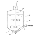
図1は、本発明におけるメタン発酵槽1内の被処理液2の撹拌を説明する概念図である。本発明で使用されるメタン発酵槽1は、円筒形又は水平方向の断面が八角形以上の多角形となる柱状体であり、下水処理場で発生する余剰汚泥を消化処理して消化ガスを取り出すように構成されている。このようなメタン発酵槽の缶体高さは、10m以上30m以下で、直径(水平方向の断面が多角形の場合は、内接円の直径は10m以上30m以下である。メタン発酵槽1内の被処理液2は、図示されていない熱交換器のような加温装置により、例えば、中温発酵に適した37℃〜40℃に保たれている。
FIG. 1 is a conceptual diagram illustrating the stirring of the liquid 2 to be processed in the
本発明を適用するメタン発酵槽1の容量は特に限定されないが、750〜6000m3であることが好ましい。メタン発酵槽1槽の容量が大きく、底面7の面積も広い場合、撹拌装置3の逆回転によって堆積物を底面の中心付近に集めるために多大なエネルギーが必要となる。
Although the capacity | capacitance of the
図2は通常運転中の被処理液2の流れを示す。メタン発酵槽1は、底面7が水平な平面であり、中央部に撹拌装置3としてモータ5に接続された2段のインペラ翼が設けられている。2段のインペラ翼の替わりに、撹拌装置3としてスクリュー翼を設けてもよく、インペラ翼を1段又は3段以上の多段としてもよい。
FIG. 2 shows the flow of the liquid 2 to be treated during normal operation. The
なお、本発明においては、インペラ式撹拌装置として、プロペラ型、パドル型、フラットパドル型、タービン型又はコーン型の撹拌装置を使用し得る。また、本発明においては、スクリュー式撹拌装置として、リボン型又はスクリュー型の撹拌装置を使用し得る。 In the present invention, a propeller type, paddle type, flat paddle type, turbine type or cone type stirring device can be used as the impeller type stirring device. In the present invention, a ribbon type or screw type stirring device can be used as the screw type stirring device.
鋼板製メタン発酵槽は、コンクリート製の土台上に設置されることが一般的であるが、土台とメタン発酵槽との間に雨水等が溜まらないように、メタン発酵槽の底面は、水平とするか、上向きに凸状となるように傾斜をつけることが好ましい。 The steel plate methane fermentation tank is generally installed on a concrete base, but the bottom of the methane fermentation tank is horizontal so that rainwater does not collect between the foundation and the methane fermentation tank. Alternatively, it is preferable to incline so as to be convex upward.
撹拌装置3は、通常、連続して運転されており、通常運転及び逆回転運転がタイマー等によって、連続して定期的に行われる。具体的には、逆回転運転は、1日1回〜4回程度の頻度で行われ、投入される汚泥量によって運転時間が調節される。撹拌翼の翼径をD、メタン発酵槽底面の直径をTとするとき、メタン発酵槽1と撹拌翼の大きさの比率は、D=0.2T以上0.3T以下とすることが好ましい。
The stirring
撹拌翼の設置場所は、撹拌翼の上端部が液面から0.5D以上浸漬させることが好ましい。多段の撹拌翼を利用する場合、最下段翼がメタン発酵槽1の底面7から0.75D〜1.5D以上離して設置することが好ましい。
As for the installation location of the stirring blade, it is preferable that the upper end of the stirring blade is immersed 0.5D or more from the liquid surface. When using a multistage stirring blade, it is preferable that the lowermost blade be installed 0.75D to 1.5D or more away from the
撹拌装置3としてスクリュー翼を設ける場合、最上段翼がメタン発酵槽1内の液面から50cm以上200cm以下となるように調整するのが好ましい。また、スクリュー翼を設ける場合、通常はドラフトチューブを設置するため、ドラフトチューブの最下部がメタン発酵槽1の底面7から2m以上15m以下となるように調整することが好ましい。
When a screw blade is provided as the stirring
被処理液2の具体例は、下水処理場で発生する汚泥又は食品廃棄物、畜産由来の糞尿等のバイオマスを含む液であるが、有機物を含有し、メタン菌の発育に悪影響を与える物質を含有していない限り、被処理液2としてメタン発酵槽1へと供給してよい。なお、メタン発酵槽に供給される上記汚泥や食品廃棄物は、事前に固形分濃度2〜10%に調整されることが好ましい。
A specific example of the liquid to be treated 2 is a liquid containing sludge generated at a sewage treatment plant or a biomass such as food waste, manure derived from livestock, etc., but contains an organic substance and has a negative effect on the growth of methane bacteria. As long as it does not contain, you may supply to the
図1(a)に示される被処理液2の流れる方向は、図5(a)と同じであり、メタン発酵槽1中央には、撹拌装置3(インペラ翼)に沿って底面7に向かう下降流が発生している。この下降流は、底面7に当たって側面方向に向きを変え、さらに側面に当たって水面に向かう上昇流が発生している。そして、撹拌装置3によって再び下降流となる。一方で、発生したバイオガスは、メタン発酵槽上部に設けられるガス取り出し口から、外部に設置されるガスホルダー(図示せず)へと取り出される。
The flow direction of the liquid 2 to be treated shown in FIG. 1 (a) is the same as that in FIG. 5 (a), and descends toward the
通常運転を継続すると、メタン発酵槽1内の被処理液2に含有されている土壌、砂若しくは金属片のような難分解性の固形物、又は髪の毛又はプラスチック片のような発酵不適物塊が徐々に堆積する。図1(a)に示されるような形状のメタン発酵槽1の場合、堆積物4は、図1(b)に示されるように、底面7に側面に近い程高く、中央に近づくほど低く堆積する。この場合、メタン発酵槽1の側面下方に設けられている消化液移送管8によっては、堆積物4を効率よく除去することができない。すなわち、消化液移送管8から被処理液2(被消化液)を引き抜くと、消化液移送管8周辺の堆積物4は、消化液移送管8を通じて除去されるが、その他大部分の堆積物4は除去されずに、そのままメタン発酵槽1の底面7に堆積した状態である。
If the normal operation is continued, the soil, sand, or hard-to-decompose solids such as metal pieces contained in the liquid to be treated 2 in the
そこで、メタン発酵槽1の底面7に配置されている堆積物引き抜き管6を開き、堆積物4を排出することも考えられるが、この場合、図2に示されるように、堆積物引き抜き管6周辺の堆積物4しか除去されない。一方で、堆積物引き抜き管6を多数(例えば10本程度)設けることも考えられるが、引き抜き効率が低く、現実的ではない。また、堆積物4を除去するために、被処理液2をすべて排水してメタン発酵槽1内を空にし、底面7を洗浄することも考えられるが、こちらの方法も、立ち上がりの時間及び運転停止日数を考慮すると現実的ではない。
Therefore, it is conceivable to open the
しかし、本発明では、通常運転を一定期間継続し、底面7の端部付近に堆積物4が堆積した場合、モータ5の回転方向を反転させ、撹拌装置3を通常運転時とは逆回転させる堆積物引き抜き工程を行う。このとき、被処理液2の流れる方向は、図3に示されるような向きとなる。このとき、底面7付近では、中心部へ向けた流れが発生するため、端部の堆積物4に水平流が加わり、堆積物4は、図4(a)に示されるように、堆積物引き抜き管6が設置されている中央へと移動される。
However, in the present invention, the normal operation is continued for a certain period, and when the
図4(a)に示される状態で、堆積物引き抜き管6に設けられているポンプPを運転することにより、中央へと集められた堆積物を、効率よく堆積物引き抜き管6から引き抜くことが可能となる。
In the state shown in FIG. 4 (a), by operating the pump P provided in the
モータ5は、図示しない制御装置によって回転速度及び回転方向が制御されている。撹拌装置3の回転速度は、正回転の場合は10〜20r/minで、逆回転の場合は正回転の40〜100%の回転速度で運転する。
The rotation speed and direction of the
撹拌装置3を逆回転させる時間は、堆積物4量に比例させてもよく、定期的に所定時間運転するようにしてもよい。通常は、1日のうち1〜4回程度、1回あたり5分〜30分程度逆回転させるが、堆積物4が多い場合には、逆回転運転の回数及び時間を増やしてもよい。
The time for reversely rotating the stirring
撹拌装置3は、上記のように定期的に逆回転運転させる以外に、センサーによって堆積物の有無を検知し、堆積物が検知された場合に、逆回転運転を行うようにしてもよい。この場合、検知後に1日数回の逆回転運転を行うようにしてもよいが、確実に堆積物を排出するために、センサー検知後、数日(例えば2〜4日)の間、1日1〜4回程度の逆回転運転を行ってもよい。
In addition to periodically rotating in the reverse direction as described above, the stirring
堆積物の有無を検知する場合、温度センサー又は超音波センサー等を利用して堆積物の有無を直接測定してもよく、メタンを含むバイオガスの発生量を測定することによって、メタン発酵槽内の有効容積の減少を予測し、間接的に堆積物の有無を測定してもよい。 When detecting the presence or absence of deposits, the presence or absence of deposits may be directly measured using a temperature sensor or ultrasonic sensor, etc., and by measuring the amount of biogas containing methane, It is also possible to predict the decrease in the effective volume of the material and indirectly measure the presence or absence of deposits.
センサーを利用して堆積物の有無を探知して堆積物除去工程を実施する場合には、その具体的な判断基準としては、例えば、缶高さに対して3〜5%となる高さまで堆積物が堆積したと判断される場合、又は消化槽の容積に対して堆積物体積が3〜5%となる体積まで堆積物が堆積したと判断される場合である。 When detecting the presence or absence of deposits using a sensor and carrying out the deposit removal step, the specific judgment criteria are, for example, deposition up to a height of 3 to 5% of the can height It is a case where it is determined that the deposit has been deposited, or a case where it is determined that the deposit has been deposited up to a volume of 3 to 5% with respect to the volume of the digester.
被処理液2の流速が低すぎると堆積物4を移動させることができず、逆に被処理液2の流速が高すぎると堆積物4が撹拌装置3によって巻き上げられてしまう。このため、堆積物引き抜き工程においては、被処理液2の流速を10cm/秒以上50cm/秒以下に調整することが好ましい。被処理液2の流速は、モータ5の出力を調整することによって制御される。
If the flow rate of the liquid 2 to be processed is too low, the
底面7の中央に移動した堆積物4は、堆積物引き抜き管6に設けられたポンプPにより、メタン発酵槽1の外へと除去される。堆積物の引き抜きは、逆回転運転時に1回以上実施され、排出時間は1回につき3〜5分程度に調整される。堆積物引き抜き工程終了後、堆積物引き抜き管6は閉じられ、堆積物4の引き抜きが停止される。堆積物引き抜き工程が繰り返される場合、再度堆積物引き抜き管6が開かれ、ポンプPを運転することによって、堆積物4が引き抜かれる。その後、逆回転運転時間が所定時間となった時点で、撹拌装置3が正回転に切り換えられ、メタン発酵槽1の通常運転に戻る。
The
なお、モータ5を正回転から逆回転に切り換える第1切換え時又は逆回転から正回転に切り換える第2切換え時に、通常、撹拌装置3は、5分程度停止される。撹拌装置3が停止されている間にも、ポンプPを運転して堆積物を排出してもよい。堆積物が排出された後、堆積物引き抜き管6は閉じられ、堆積物4の引き抜きが停止される。
The stirring
撹拌装置3の停止時に堆積物を引き抜くことによって、被処理液2の撹拌によって浮遊している固形物が塊状になって移送させにくくなる前に、固形物を排出させることが可能となる。
By pulling out the deposit when the stirring
なお、通常メタン発酵槽1は、中温発酵の場合には、滞留時間が20〜30日で連続的に運転されるため、被処理物をメタン発酵槽1へと供給した際に、被処理液2の増加量に合わせて、メタン発酵槽1内の被処理液2がポンプ又は水位差を利用した自然吸引により引き抜かれる。このため、本発明においては、汚泥引き抜き運転を、被処理物の投入のタイミングに合わせてもよく、被処理物の投入と関係なく実施してもよい。
In addition, since the
消化液移送配管8又は堆積物引き抜き管6から引き抜かれた被処理液又は堆積物は、適宜二次メタン発酵槽のような生物処理槽へと供給され、残存する有機物をさらに生物学的に分解されてもよく、脱水機等により脱水されてもよい。脱水された場合、脱水ろ液は別途、水処理に付され、脱水物は焼却又は廃棄されてもよい。
The liquid to be treated or the sediment drawn from the digestion
消化液移送配管8を設けず、堆積物引き抜き管6を消化液の移送管として利用することも可能である。消化液移送配管8を独立して設ける場合には、消化液移送配管8を設置する高さを調整することにより、消化液と堆積物とが混ざることを抑制し得る。一方、消化液移送配管8を底面付近に設置することにより、消化液移送配管8からも堆積物の一部を引き抜くことも可能である。
It is also possible to use the
メタン発酵槽1には、被消化液2の液温をメタン発酵に適した温度範囲に調整するための加温装置(図示せず)を設けてもよい。また、堆積物引き抜き管6又は消化液移送管8から移送される消化液をメタン発酵槽へと循環するための循環ライン(図示せず)を設け、この返送経路に液温を調整するための加熱装置を設け、加熱後の被処理液をメタン発酵槽1へと返送してもよい。
The
[実施例]
直径10m、高さ11mの円筒形の鋼板製消化槽を利用して実験を行った。消化槽には750m3の被処理物が投入され、消化槽の内部には直径約2mのインペラ式の撹拌翼が2段設置され(消化槽下部からそれぞれ、2m及び8mの高さ)、15rpmで撹拌翼を回転させた。メタン発酵対象となる汚泥を30m3/日で供給し、滞留時間25日でメタン発酵を行った。
[Example]
The experiment was performed using a cylindrical steel plate digestion tank with a diameter of 10 m and a height of 11 m. The digester is turned the object to be processed of 750 meters 3, the interior of the digester is provided two-stage stirring blades of the impeller type with a diameter of about 2m (height of each from the digester bottom, 2m and 8m), 15 rpm The agitating blade was rotated. The sludge to be subjected to methane fermentation was supplied at 30 m 3 / day, and methane fermentation was performed with a residence time of 25 days.
(堆積物の測定)
タンク中心から外壁に向けて1m毎に、上部から探触子を利用して堆積物の高さを測定した。中心から同じ距離となる部分には同じ量の堆積物が堆積していると仮定して等高線を引いた。消化槽における堆積物高さから堆積物の体積を求め、消化槽に対する堆積物の容積割合(堆積物体積/消化槽の容積)を算出した。
(Measurement of sediment)
The height of the sediment was measured from the top using a probe every 1 m from the center of the tank to the outer wall. Contour lines were drawn on the assumption that the same amount of sediment was deposited in the same distance from the center. The volume of the deposit was obtained from the height of the deposit in the digestion tank, and the volume ratio of the deposit to the digestion tank (deposit volume / volume of the digestion tank) was calculated.
なお、探触子は、紐の先端におもりを付けたものであり、堆積物が存在するとおもりが消化槽の底まで沈まずに途中で止まるため、おもりが沈む深さを測定することで、堆積物の堆積高さを測定することが可能となる。 The probe has a weight attached to the tip of the string, and if there is a deposit, the weight stops to the middle of the digestion tank without sinking, so by measuring the depth at which the weight sinks, It becomes possible to measure the height of the deposit.
(逆回転運転の実施)
消化運転開始後、堆積物が徐々に堆積しはじめ、約4ヶ月経過後に、上述した消化槽に対する堆積物の容積割合(堆積物体積/消化槽容積)が3.5%程度となったと判断された。そこで、通常運転に加えて撹拌機の逆回転運転(15rpmで数分間、4〜5回/日)を行い、撹拌機の逆回転に合わせて消化液の引き抜きを行った。
(Implementation of reverse rotation)
After the start of the digestion operation, the sediment began to gradually accumulate, and after about 4 months, it was judged that the volume ratio of the sediment to the digestion tank (deposit volume / digestion tank volume) was about 3.5%. Therefore, in addition to the normal operation, the agitator was reversely rotated (15 rpm, several minutes, 4 to 5 times / day), and the digestive juice was extracted in accordance with the reverse rotation of the agitator.
メタン発酵の通常の運転に、逆回転運転による堆積物の排出運転を組み合わせた運転を10日間行い、探触子を利用して消化槽内の堆積物の堆積状況を確認したところ、消化槽に対する堆積物の容積割合は2.5%まで低下していることが確認された。その後も4ヶ月間運転を継続したが、上記と同様の逆回転運転を行うことで、堆積物の堆積状況は2.5%程度まで低下できることが確認された。 The normal operation of methane fermentation was combined with the sediment discharge operation by reverse rotation operation for 10 days, and the deposit status of the deposit in the digestion tank was confirmed using a probe. It was confirmed that the volume fraction of the deposit was reduced to 2.5%. After that, the operation was continued for 4 months, but it was confirmed that the deposit status could be reduced to about 2.5% by performing the reverse rotation operation similar to the above.
本発明のメタン発酵槽の運転方法は、廃水処理及びエネルギーの分野において有用である。 The operation method of the methane fermenter of the present invention is useful in the fields of wastewater treatment and energy.
1,11:メタン発酵槽
2,12:被処理液(被消化液)
3,13:撹拌装置
4,14:堆積物
5,15:モータ
6,16:堆積物引き抜き管
7,17:底面
8:消化液移送管
P:ポンプ
1, 11:
3, 13:
具体的に、本発明は、
メタン発酵槽の運転方法であって、
前記メタン発酵槽は、
水平な底面を有するか、上向き又は下向きに凸状であり、端部と中心部とを結ぶ直線が水平線となす角度が0.3度以上1度以下である底面を有する円筒形であって、
中心部には被処理液を撹拌するスクリュー式又はインペラ式の撹拌装置が設けられており、
中心部には被処理液を撹拌するスクリュー式又はインペラ式の撹拌装置が設けられており、
底面中央部には堆積物引き抜き管が配置されており、
前記運転方法は、通常運転と堆積物引き抜き運転を交互に行い、
通常運転時には、前記スクリュー式又はインペラ式の撹拌装置を回転させることによって、メタン発酵槽中央には底面に向かって下降流が発生し、メタン発酵槽側面には水面に向かって上昇流が発生しており、
堆積物引き抜き運転時には、前記スクリュー式又はインペラ式の撹拌装置を通常運転時と逆回転させることによって、メタン発酵槽中央には水面に向かって上昇流が発生し、側面には底面に向かって下向流が発生しており、前記堆積物引き抜き管から底面中央部に集めた堆積物をメタン発酵槽外へと排出することを特徴とする運転方法に関する。
Specifically, the present invention
A method for operating a methane fermentation tank,
The methane fermenter is
Or with a horizontal bottom surface is convex upward or downward, the straight line connecting the end portion and the central portion a cylindrical shape with a bottom angle is 1 degree or less than 0.3 degrees, which forms a horizontal line,
In the center, a screw type or impeller type stirring device for stirring the liquid to be treated is provided,
In the center, a screw type or impeller type stirring device for stirring the liquid to be treated is provided,
At the center of the bottom is a sediment extraction tube,
The operation method is to perform a normal operation and a deposit extraction operation alternately,
During normal operation, by rotating the screw type or impeller type stirring device, a downward flow is generated at the center of the methane fermentation tank toward the bottom surface, and an upward flow is generated at the side of the methane fermentation tank toward the water surface. And
During the sediment extraction operation, the screw-type or impeller-type stirring device is rotated in the reverse direction to that during normal operation, so that an upward flow is generated toward the water surface in the center of the methane fermentation tank, and the bottom surface is directed toward the bottom surface. The present invention relates to an operation method characterized in that countercurrent is generated and deposits collected at the center of the bottom surface from the deposit extraction pipe are discharged out of the methane fermentation tank.
Claims (4)
前記メタン発酵槽は、
略水平な底面を有する円筒形であって、
中心部には被処理液を撹拌するスクリュー式又はインペラ式の撹拌装置が設けられており、
底面中央部には堆積物引き抜き管が配置されており、
前記運転方法は、通常運転と堆積物引き抜き運転を交互に行い、
通常運転時には、前記スクリュー式又はインペラ式の撹拌装置を回転させることによって、メタン発酵槽中央には底面に向かって下降流が発生し、メタン発酵槽側面には水面に向かって上昇流が発生しており、
堆積物引き抜き運転時には、前記スクリュー式又はインペラ式の撹拌装置を通常運転時と逆回転させることによって、メタン発酵槽中央には水面に向かって上昇流が発生し、側面には底面に向かって下向流が発生しており、前記堆積物引き抜き管から底面中央部に集めた堆積物をメタン発酵槽外へと排出することを特徴とする、運転方法。 A method for operating a methane fermentation tank,
The methane fermenter is
A cylindrical shape having a substantially horizontal bottom surface,
In the center, a screw type or impeller type stirring device for stirring the liquid to be treated is provided,
At the center of the bottom is a sediment extraction tube,
The operation method is to perform a normal operation and a deposit extraction operation alternately,
During normal operation, by rotating the screw type or impeller type stirring device, a downward flow is generated at the center of the methane fermentation tank toward the bottom surface, and an upward flow is generated at the side of the methane fermentation tank toward the water surface. And
During the sediment extraction operation, the screw-type or impeller-type stirring device is rotated in the reverse direction to that during normal operation, so that an upward flow is generated toward the water surface in the center of the methane fermentation tank, and the bottom surface is directed toward the bottom surface. A counter flow is generated, and the deposit collected in the center of the bottom from the deposit extraction pipe is discharged out of the methane fermentation tank.
前記スクリュー式又はインペラ式の撹拌装置の撹拌翼の翼径Dが0.2〜0.3Tであり、
前記メタン発酵槽の缶体高さが0.8〜1.2Tであり、
前記メタン発酵槽内の被処理液の深さが0.8〜1.0Tであり、
前記スクリュー式又はインペラ式の撹拌装置の撹拌翼の上端部が被処理液の液面から0.5D以上浸漬している、請求項1乃至3のいずれか1項に記載のメタン発酵槽の運転方法。 When the diameter of the bottom of the methane fermentation tank is T, the methane fermentation tank and the screw type or impeller type stirring device,
The blade diameter D of the stirring blade of the screw type or impeller type stirring device is 0.2 to 0.3 T,
The can height of the methane fermentation tank is 0.8 to 1.2 T,
The depth of the liquid to be treated in the methane fermentation tank is 0.8 to 1.0 T,
The operating method of the methane fermenter of any one of Claims 1 thru | or 3 with which the upper end part of the stirring blade of the said screw type or impeller type stirring apparatus is immersed 0.5D or more from the liquid level of a to-be-processed liquid. .
Priority Applications (1)
| Application Number | Priority Date | Filing Date | Title |
|---|---|---|---|
| JP2013036201A JP5351346B1 (en) | 2013-02-26 | 2013-02-26 | Operation method of methane fermentation tank |
Applications Claiming Priority (1)
| Application Number | Priority Date | Filing Date | Title |
|---|---|---|---|
| JP2013036201A JP5351346B1 (en) | 2013-02-26 | 2013-02-26 | Operation method of methane fermentation tank |
Related Child Applications (1)
| Application Number | Title | Priority Date | Filing Date |
|---|---|---|---|
| JP2013171545A Division JP5412598B1 (en) | 2013-08-21 | 2013-08-21 | Operation method of methane fermentation tank |
Publications (2)
| Publication Number | Publication Date |
|---|---|
| JP5351346B1 JP5351346B1 (en) | 2013-11-27 |
| JP2014161813A true JP2014161813A (en) | 2014-09-08 |
Family
ID=49764967
Family Applications (1)
| Application Number | Title | Priority Date | Filing Date |
|---|---|---|---|
| JP2013036201A Active JP5351346B1 (en) | 2013-02-26 | 2013-02-26 | Operation method of methane fermentation tank |
Country Status (1)
| Country | Link |
|---|---|
| JP (1) | JP5351346B1 (en) |
Cited By (5)
| Publication number | Priority date | Publication date | Assignee | Title |
|---|---|---|---|---|
| JP5943528B1 (en) * | 2015-10-29 | 2016-07-05 | 巴工業株式会社 | Polymer flocculant mixing dissolution system and polymer flocculant mixing dissolution method |
| JP2018202321A (en) * | 2017-06-05 | 2018-12-27 | 前澤工業株式会社 | Methane fermentation tank |
| JP2019141847A (en) * | 2019-06-10 | 2019-08-29 | 佐竹化学機械工業株式会社 | Agitation method |
| JP2022127198A (en) * | 2021-02-19 | 2022-08-31 | 株式会社神鋼環境ソリューション | Method for detecting sediment in methane fermentation tank made of steel plate, method for removing sediment in methane fermentation tank made of steel plate, and system for detecting sediment in methane fermentation tank made of steel plate |
| JP2022133244A (en) * | 2021-03-01 | 2022-09-13 | プライミクス株式会社 | Agitation device |
Families Citing this family (3)
| Publication number | Priority date | Publication date | Assignee | Title |
|---|---|---|---|---|
| JP5580500B1 (en) * | 2014-02-10 | 2014-08-27 | 株式会社神鋼環境ソリューション | Steel plate digester |
| JP5998167B2 (en) * | 2014-03-24 | 2016-09-28 | 株式会社神鋼環境ソリューション | Digestion tank and method for discharging sludge in the digestion tank |
| CN113620736B (en) * | 2021-07-26 | 2022-09-30 | 长沙县东牛农业有限公司 | Edible mushroom is cultivated with liquid fertilizer mixed fermentation device |
-
2013
- 2013-02-26 JP JP2013036201A patent/JP5351346B1/en active Active
Cited By (10)
| Publication number | Priority date | Publication date | Assignee | Title |
|---|---|---|---|---|
| JP5943528B1 (en) * | 2015-10-29 | 2016-07-05 | 巴工業株式会社 | Polymer flocculant mixing dissolution system and polymer flocculant mixing dissolution method |
| JP2017080686A (en) * | 2015-10-29 | 2017-05-18 | 巴工業株式会社 | Mixture melting system for high molecular coagulant and mixture melting method for high molecular coagulant |
| JP2018202321A (en) * | 2017-06-05 | 2018-12-27 | 前澤工業株式会社 | Methane fermentation tank |
| JP2019141847A (en) * | 2019-06-10 | 2019-08-29 | 佐竹化学機械工業株式会社 | Agitation method |
| JP2022127198A (en) * | 2021-02-19 | 2022-08-31 | 株式会社神鋼環境ソリューション | Method for detecting sediment in methane fermentation tank made of steel plate, method for removing sediment in methane fermentation tank made of steel plate, and system for detecting sediment in methane fermentation tank made of steel plate |
| JP7263411B2 (en) | 2021-02-19 | 2023-04-24 | 株式会社神鋼環境ソリューション | Method for detecting sediment in steel plate methane fermentation tank, method for removing sediment in steel plate methane fermentation tank, and sediment detection system for steel plate methane fermentation tank |
| JP2022133244A (en) * | 2021-03-01 | 2022-09-13 | プライミクス株式会社 | Agitation device |
| JP7219831B2 (en) | 2021-03-01 | 2023-02-08 | プライミクス株式会社 | stirrer |
| JP7245594B1 (en) | 2021-03-01 | 2023-03-24 | プライミクス株式会社 | stirrer |
| JP2023046329A (en) * | 2021-03-01 | 2023-04-03 | プライミクス株式会社 | Agitation device |
Also Published As
| Publication number | Publication date |
|---|---|
| JP5351346B1 (en) | 2013-11-27 |
Similar Documents
| Publication | Publication Date | Title |
|---|---|---|
| JP5351346B1 (en) | Operation method of methane fermentation tank | |
| Kariyama et al. | Influence of mixing on anaerobic digestion efficiency in stirred tank digesters: A review | |
| US20050230308A1 (en) | Induced sludge bed anaerobic reactor | |
| CN101823793B (en) | Double-path circulation full-mixing type anaerobic reactor | |
| WO2016050893A1 (en) | Methods and bioreactors for microbial digestion using immobilized biofilms | |
| CN105417912A (en) | Dewatered-sludge anaerobic dry fermentation device | |
| CN106434296B (en) | Integrated dry-wet anaerobic digestion device | |
| GB2035373A (en) | Gas collection apparatus | |
| JP5412598B1 (en) | Operation method of methane fermentation tank | |
| CN105820943B (en) | A kind of multi-stage gas-liquid joint stirring Venturi tube-CSTR reaction units | |
| CN201132800Y (en) | Highly effective mixing upwash reactor for anaerobic solid | |
| CN204912250U (en) | Kitchen garbage homogenate edulcoration device | |
| CN206143198U (en) | Integral type is wet anaerobic digestion device futilely | |
| CN108947137A (en) | A kind of kitchen garbage percolation liquid treatment method | |
| CN203833929U (en) | Complete mixed anaerobic bioreactor | |
| CN202594857U (en) | Anaerobic reaction device for treating wastewater with high solid content | |
| CN208517385U (en) | A kind of pretreatment line for marsh gas power generation | |
| CN107304403A (en) | A kind of new batch-type anaerobic reaction technique | |
| CN201914971U (en) | Barrel-shaped spiral upstream anaerobic device | |
| CN201338981Y (en) | High-efficiency intermittent stirring anaerobic solid reactor device with three-phase separating function | |
| JP6503253B2 (en) | Stirring method of anaerobic fermentation tank | |
| JP6027042B2 (en) | Digestion tank operation method and digestion tank | |
| CN104357320B (en) | Straw pretreatment/biphase fermentation/automatic shell-breaking integrated apparatus | |
| WO2012168341A1 (en) | Waste digestion | |
| CN113388492A (en) | Hydrolysis-impurity removal device and method for fruit and vegetable garbage slurry |
Legal Events
| Date | Code | Title | Description |
|---|---|---|---|
| TRDD | Decision of grant or rejection written | ||
| R150 | Certificate of patent or registration of utility model |
Ref document number: 5351346 Country of ref document: JP Free format text: JAPANESE INTERMEDIATE CODE: R150 Free format text: JAPANESE INTERMEDIATE CODE: R150 |
|
| R250 | Receipt of annual fees |
Free format text: JAPANESE INTERMEDIATE CODE: R250 |
|
| R250 | Receipt of annual fees |
Free format text: JAPANESE INTERMEDIATE CODE: R250 |
|
| R250 | Receipt of annual fees |
Free format text: JAPANESE INTERMEDIATE CODE: R250 |
|
| R250 | Receipt of annual fees |
Free format text: JAPANESE INTERMEDIATE CODE: R250 |
|
| R250 | Receipt of annual fees |
Free format text: JAPANESE INTERMEDIATE CODE: R250 |
|
| R250 | Receipt of annual fees |
Free format text: JAPANESE INTERMEDIATE CODE: R250 |
|
| R250 | Receipt of annual fees |
Free format text: JAPANESE INTERMEDIATE CODE: R250 |
|
| R250 | Receipt of annual fees |
Free format text: JAPANESE INTERMEDIATE CODE: R250 |