JP2014158317A - Cable display implement - Google Patents
Cable display implement Download PDFInfo
- Publication number
- JP2014158317A JP2014158317A JP2013026575A JP2013026575A JP2014158317A JP 2014158317 A JP2014158317 A JP 2014158317A JP 2013026575 A JP2013026575 A JP 2013026575A JP 2013026575 A JP2013026575 A JP 2013026575A JP 2014158317 A JP2014158317 A JP 2014158317A
- Authority
- JP
- Japan
- Prior art keywords
- cable
- sheet material
- indicator
- sheet
- layer sheet
- Prior art date
- Legal status (The legal status is an assumption and is not a legal conclusion. Google has not performed a legal analysis and makes no representation as to the accuracy of the status listed.)
- Pending
Links
- 239000000463 material Substances 0.000 claims abstract description 63
- 239000011347 resin Substances 0.000 claims abstract description 9
- 229920005989 resin Polymers 0.000 claims abstract description 9
- 239000003086 colorant Substances 0.000 claims abstract description 5
- 238000004804 winding Methods 0.000 abstract description 6
- 238000010030 laminating Methods 0.000 abstract 1
- 230000002093 peripheral effect Effects 0.000 description 5
- 229920002725 thermoplastic elastomer Polymers 0.000 description 3
- RYGMFSIKBFXOCR-UHFFFAOYSA-N Copper Chemical compound [Cu] RYGMFSIKBFXOCR-UHFFFAOYSA-N 0.000 description 1
- 230000005856 abnormality Effects 0.000 description 1
- 229910052802 copper Inorganic materials 0.000 description 1
- 239000010949 copper Substances 0.000 description 1
- 230000000694 effects Effects 0.000 description 1
- 238000001125 extrusion Methods 0.000 description 1
- 230000012447 hatching Effects 0.000 description 1
- 238000004519 manufacturing process Methods 0.000 description 1
- 238000000034 method Methods 0.000 description 1
- 230000003287 optical effect Effects 0.000 description 1
- XLYOFNOQVPJJNP-UHFFFAOYSA-N water Substances O XLYOFNOQVPJJNP-UHFFFAOYSA-N 0.000 description 1
Images
Landscapes
- Insulated Conductors (AREA)
- Electric Cable Installation (AREA)
Abstract
Description
本発明は、ケーブルに装着されて、ケーブルの種類等を外観で識別するのに使用されるケーブル表示具に関する。 The present invention relates to a cable indicator that is attached to a cable and used to identify the type of the cable and the like by appearance.
電柱には、電力線(電線)や電話線以外に、ケーブルテレビや有線放送用のケーブルなど種々の通信用ケーブルが共架され、また通信用ケーブルにも従来より使われている銅線ケーブル、近年よく使われている光ケーブルがあって、非常に複雑な配線となっており、従ってケーブルに異常が発生した時などに、どのケーブルか見分けがつき難いことから、これらのケーブルにはその種類等を外観で識別するためのケーブル表示具が取り付けられている。 In addition to power lines (electric wires) and telephone lines, various types of communication cables such as cable TV and cable for cable broadcasting are co-mounted on the utility poles, and copper cables that have been used for communication cables have been used in recent years. There are optical cables that are often used, and the wiring is very complicated. Therefore, it is difficult to distinguish which cable when an abnormality occurs in the cable. A cable indicator for identification by appearance is attached.
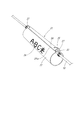
従来のケーブル表示具として、特許公報等の公知文献を具体的に挙げることはできないが、従来使用されているケーブル表示具を図4に示すと、ここに示すケーブル表示具21は、硬質樹脂により丸い筒状に形成された筒状本体22と、筒状本体22の開口部23の一端側にある係止部24と、開口部23の他端側にある被係止部25とからなるもので、筒状本体22の側面にケーブルの種類等を表示する文字26が印刷されている。そして、ケーブル10への取付けにあたっては、係止部24の先端鉤片24aを被係止部25から外して開口部23を開き、この開口部23からケーブル10を筒状本体22内に挿入した状態とした後、係止部24の先端鉤片24aを被係止部25に対しスナップ式に係止して開口部23を閉鎖し、係止部24の両端部側を夫々被覆針金27によってケーブル10に縛り付けるようにしている。
As a conventional cable indicator, publicly known documents such as patent gazettes cannot be specifically mentioned, but when a conventionally used cable indicator is shown in FIG. 4, the
上記従来のケーブル表示具21では、硬質樹脂により形成されたもので、ケーブル10に対してぶら下げた状態に取り付けられることから、取り付けるのに手間がかかる上に、風で揺れ動くため、係止部24及び被係止部25がケーブル10に当たって傷つけ易く、また筒状本体22に印刷されている印刷文字26が雨水によって剥げ易く、また径年変化により消失し易くなる、と云った問題がある。
The
本発明は、上記の事情に鑑み、ケーブルへの取付けが簡単で、表示した文字が消失するようなことがなく、またケーブルを傷つけるようなことのないケーブル表示具を提供することを目的とする。 SUMMARY OF THE INVENTION In view of the above circumstances, an object of the present invention is to provide a cable indicator that is easy to attach to a cable, does not lose displayed characters, and does not damage the cable. .
上記課題を解決するための手段を、後述する実施形態の参照符号を付して説明すると、請求項1に係る発明は、ケーブル10に装着されて、ケーブル10の種類等を表示するケーブル表示具1であって、夫々軟質樹脂製で互いに異系色の内側シート材2と外側シート材3とがラミネートされた二層シート4からなり、外側シート材3には表示すべき所定の文字5が彫刻形成されて、その彫刻文字5が内側シート材2のベース色によって顕現しており、この二層シート4には前記ケーブル10に巻き付いて固定されるように巻き癖がつけられていることを特徴とする。
Means for solving the above problems will be described with reference numerals in the embodiments described later. The invention according to claim 1 is a cable indicator that is attached to the
請求項2は、請求項1に記載のケーブル表示具において、前記二層シート4は、断面略渦巻き形状ないし略「の」字形状に巻き癖がつけられていることを特徴とする。
According to a second aspect of the present invention, in the cable display device according to the first aspect, the two-
請求項3は、請求項1又は2に記載のケーブル表示具において、前記内側シート材2の内面には、シート幅方向に所定間隔をおいて複数の突起部6がシート全長にわたって条設されていることを特徴とする。
According to a third aspect of the present invention, in the cable indicator according to the first or second aspect, a plurality of
上記解決手段による発明の効果を、後述する実施形態の参照符号を付して説明すると、請求項1に係る発明のケーブル表示具は、夫々軟質樹脂製で互いに異系色の内側シート材2と外側シート材3とがラミネートされた二層シート4からなるもので、外側シート材3に所定の文字が彫刻形成されて、その彫刻文字5が内側シート材2のベース色によって顕現し、そして二層シート4にはケーブル10に巻き付いて固定されるように巻き癖がつけられている構成であるから、二層シート4に表示した文字5は、従来のケーブル表示具のように径年変化により消失したり、雨水により剥げるおそれがなく、長期にわたり文字機能を維持することができ、また二層シート4がケーブル10に巻き付いて固定されるため、ケーブル10を傷つけることがなく、風圧等でケーブル10から外れるようなこともない。またケーブル10に取り付けるには、二層シート4をその巻き癖を解くように拡開した状態で、その内面側をケーブル10に押し当てるようにすれば、この二層シート4が半自動的にケーブル10の外周沿いに巻き付いてケーブル10に固定されるから、取付けが非常に簡単容易となる。
The effect of the invention by the above means will be described with reference numerals in the embodiments described later. The cable display device of the invention according to claim 1 is made of a soft resin made of a different color and the
請求項2に係る発明のように、二層シート4は、断面略渦巻き形状ないし略「の」字形状に巻き癖がつけられているから、ケーブル10に対し十分な巻き付き力を発揮して、的確に取付け固定させることができる。
As in the invention according to
請求項3に係る発明のように、内側シート材2の内面には、シート幅方向に所定間隔をおいて複数の突起部6がシート全長にわたって条設されているから、二層シート4の内側シート材2がケーブル10の外周面に対し線接触状態となり、従ってケーブル表示具1をケーブル10に固定させた状態で、その取付位置を変更したい時は、ケーブル表示具1を掴んだ状態でケーブル10に沿って押し引きすれば、ケーブル表示具1を容易に移動させることができる。
As in the invention according to
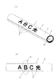
以下に本発明の好適な一実施形態を図面に基づいて説明すると、図1の(a) ,(b) に示すケーブル表示具1は、夫々軟質樹脂製で互いに異系色の内側シート材2と外側シート材3とがラミネートされた二層シート4からなるもので、外側シート材3には表示すべき所定の文字5が彫刻によって打ち抜き形成されていて、その彫刻文字5が内側シート材2のベース色によって顕現しており、そしてこの二層シート4には、当該表示具1が取り付けられるケーブル10(図3参照)に巻き付いて固定されるように巻き癖がつけられている。
A preferred embodiment of the present invention will be described below with reference to the drawings. A cable indicator 1 shown in FIGS. 1A and 1B is made of a soft resin and has an
上記ケーブル表示具1の構造について更に詳しく説明すれば、二層シート4を形成する内側シート材2及び外側シート材3は、夫々軟質樹脂、例えば熱可塑性エラストマーによって形成され、内側シート材2の厚みは外側シート材3の例えば3〜4倍となっている。この場合、内側シート材2は、シート材全体が例えば黒色に着色され、また外側シート材3は、シート材全体が内側シート材2の黒色とは異系色である例えば黄色に着色されている。
The structure of the cable indicator 1 will be described in more detail. The
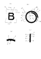
図2の(a) は図1の(b) の矢印Xで囲まれた部分の拡大図であり、図2の(b) は(a) のY−Y線断面図であり、(c) は(b) の矢印Vで囲まれた断面円弧状二層シート4部分を平面状に延ばした状態を示したもので、これらの図面から分かるように、外側シート材3に形成された彫刻文字5は、外側シート材3自体の黄色と、内側シート材2のベース色である黒色によって顕現し、ハッキリと読み取れるようになっている。
2 (a) is an enlarged view of a portion surrounded by an arrow X in FIG. 1 (b), FIG. 2 (b) is a sectional view taken along line YY in (a), and (c) (B) shows a state in which the cross-section arc-shaped double-
また、内側シート材2の内面には、シート幅方向に所定間隔をおいて複数の突起部6がシート全長にわたって条設されている。この突起部6は、ケーブル10にケーブル表示具1を巻き付けて固定した状態で移動調整したい時にスライドできるようにするためのものである。即ち、このような突起部6が設けられていないと、内側シート材2の内周面がケーブル10の外周面に対し面接触して密着状態となって、ケーブル10の長手方向にスライドさせることが困難となる。従って、このような突起部6を内側シート材2の内面にシート幅方向に所定間隔をおいてシート全長に条設することにより、ケーブル表示具1は、ケーブル10に巻き付いて固定した状態でも、内側シート材2がケーブル10に対し線接触状態であるから、ケーブル10に沿って移動させ易くなる。
A plurality of
上記ケーブル表示具1の製造方法の一例を概略説明すると、図示は省略するが、先ず、例えば熱可塑性エラストマーからなる黒色に着色された内側シート材形成材料と、同じく熱可塑性エラストマーからなる黄色に着色された外側シート材形成材料とを、二層共押出機により押し出して、黒色で内面側に突起部6を条設した内側シート材2と黄色の外側シート材3とからなる長方形状の二層シート4を渦巻き形状ないし略「の」字形状で共押出形成する。その後、二層シート4の外側シート材3に、文字彫刻機によって所定の文字を彫刻形成する。なお、内側シート材2に文字を打ち込んだ二層シート4に、所定温度に加熱される巻き癖付け機によって、所定のケーブル10に自ら巻き付いて固定されるような巻き癖をつけることもできる。この場合、ケーブル表示具1の二層シート4には、図2の(b) に示すように、断面形状が略のの字形状となるように巻き癖がつけられる。
An example of a method for manufacturing the cable display 1 will be described in brief. Although not shown, first, for example, the inner sheet material forming material colored in black made of a thermoplastic elastomer and colored in yellow made of a thermoplastic elastomer are used. The formed outer sheet material is extruded by a two-layer co-extrusion machine, and is formed into a rectangular two-layer structure composed of an
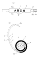
上記のような構成よりなるケーブル表示具1の使用にあたっては、図2の(b) に示されるように断面略渦巻き形状ないし「の」字形状(あるいはのの字形状)に巻き癖が付けられている二層シート4を、その内端部4a側を一方の手で保持し、外端部4b側を他方の手で掴んで外方へ引っ張るようにして(図3の(b) 参照)、二層シート4の全体を断面略Cの字状に拡開した状態で、内側シート材2側をケーブル10に押し当てて、その後に二層シート4の外端部4b側を解放すれば、その巻き癖によって二層シート4は、半自動的にケーブル10の外周沿いに巻き付いて図3の(b) の実線図示のようにケーブル10に取付け固定される。図3の(a) は、ケーブル表示具1がケーブル10に取付け固定された状態を示す。図3の(a) において、10aはケーブル10のケーブル本体、10bはケーブル本体10aを被覆している被覆部である。尚、図3の(b) のケーブル10を示す断面図では、ケーブル本体10a及び被覆部10bの図示を省略し、単にケーブル10として1種類のハッチングで示している。
When using the cable indicator 1 having the above-described configuration, as shown in FIG. 2 (b), a winding rod is attached to a substantially spiral shape or "" shape "(or" "shape). Hold the inner end 4a side with one hand and hold the
上記のようにケーブル表示具1がケーブル10に取付け固定された状態で、その取付位置を変更したい時は、ケーブル表示具1を掴んだ状態でケーブル10に沿って押し引きすれば、ケーブル表示具1を容易に位置変更させることができる。これは、前述したように、内側シート材2の内面に突起部6をシート幅方向に所定間隔をおいてシート全長に設けていることにより、二層シート4の内側シート材2がケーブル10に対し線接触状態となっているからである。
When the cable indicator 1 is attached and fixed to the
また、二層シート4は、図2の(b) に示すように、長さ方向両端部4a,4bが夫々、先端に向かって漸次薄くなっているが、これは、ケーブル10に巻き付ける際、その内端部4aに他のシート4部分が重なった時に、内端部4aの先端側に形成される隙間S(図3の(b) 参照)をできるだけ小さくして、ケーブル10に対する二層シート4の巻き付け状態を良好にすると共に、外端部4bとケーブル10外周面との段差を小さくして、外観上の体裁、見栄えを良くするためである。
Further, as shown in FIG. 2 (b), the two-
以上説明したように、このケーブル表示具1は、夫々軟質樹脂製で互いに異系色の内側シート材2と外側シート材3とがラミネートされた二層シート4からなるもので、外側シート材3には表示すべき所定の文字5が彫刻形成されて、その彫刻文字5が内側シート材2のベース色によって顕現し、この二層シート4にはケーブル10に巻き付いて固定されるように巻き癖がつけられているから、二層シート4に表示した文字5は、従来のケーブル表示具のように径年変化により消失したり、雨水により剥げるおそれがなく、長期にわたって文字機能を維持することができる。また、二層シート4がケーブル10に巻き付いて固定されるため、ケーブル10を傷つけることがなく、風圧等でケーブル10から外れるようなこともない。またケーブル10に取り付けるには、二層シート4をその巻き癖を解くように拡開した状態で、その内面側をケーブル10に押し当てるようにすれば、この二層シート4が巻き癖により半自動的にケーブル10の外周沿いに巻き付いてケーブル10に固定されるから、ケーブル表示具1の取付けが非常に簡単、容易となる。
As described above, the cable indicator 1 is composed of the two-
また、この実施形態では、ケーブル表示具1の二層シート4は、断面略渦巻き形状ないし「の」字形状に巻き癖がつけられていて、二層シート4の両端部側(内端部4a側と外端部4b側)が十分にラップするようになっているが、二層シート4の巻き癖は、そのような断面略のの字形状に限るものではなく、二層シート4をケーブル10に巻きつけた時にケーブル10外周面の一部が露呈するような断面略C字形状となるように巻き癖がつけられてもよい。ただし、実施形態のように、二層シート4に断面略のの字形状の巻き癖をつけることにより、二層シート4の両端部側(内端部4a側と外端部4b側)が十分にラップして、ケーブル10に対し十分な巻き付き力を発揮して、的確に取付け固定させることができる。
Further, in this embodiment, the two-
また、この実施形態では、内側シート材2が黒色に着色されたもの、外側シート材3が内側シート材2の黒色とは異系色の黄色に着色されたものを使用しているが、外側シート材3が赤色、内側シート材2が白色に夫々着色されたものでもよいし、また外側シート材3が黒色、内側シート材2が赤色に夫々着色されたものでもよく、いずれにしても、外側シート材3の彫刻文字5が内側シート材2のベース色によって顕現し得るものであればよい。
In this embodiment, the
1 ケーブル表示具
2 内側シート材
3 外側シート材
4 二層シート
5 彫刻文字
6 突起部
10 ケーブル
DESCRIPTION OF SYMBOLS 1
Claims (3)
Priority Applications (1)
| Application Number | Priority Date | Filing Date | Title |
|---|---|---|---|
| JP2013026575A JP2014158317A (en) | 2013-02-14 | 2013-02-14 | Cable display implement |
Applications Claiming Priority (1)
| Application Number | Priority Date | Filing Date | Title |
|---|---|---|---|
| JP2013026575A JP2014158317A (en) | 2013-02-14 | 2013-02-14 | Cable display implement |
Publications (1)
| Publication Number | Publication Date |
|---|---|
| JP2014158317A true JP2014158317A (en) | 2014-08-28 |
Family
ID=51578881
Family Applications (1)
| Application Number | Title | Priority Date | Filing Date |
|---|---|---|---|
| JP2013026575A Pending JP2014158317A (en) | 2013-02-14 | 2013-02-14 | Cable display implement |
Country Status (1)
| Country | Link |
|---|---|
| JP (1) | JP2014158317A (en) |
Citations (2)
| Publication number | Priority date | Publication date | Assignee | Title |
|---|---|---|---|---|
| JPH059444A (en) * | 1991-07-03 | 1993-01-19 | Sekisui Chem Co Ltd | Decorative adhesive sheet |
| JP2004282933A (en) * | 2003-03-18 | 2004-10-07 | Meidensha Corp | Mark band for wiring |
-
2013
- 2013-02-14 JP JP2013026575A patent/JP2014158317A/en active Pending
Patent Citations (2)
| Publication number | Priority date | Publication date | Assignee | Title |
|---|---|---|---|---|
| JPH059444A (en) * | 1991-07-03 | 1993-01-19 | Sekisui Chem Co Ltd | Decorative adhesive sheet |
| JP2004282933A (en) * | 2003-03-18 | 2004-10-07 | Meidensha Corp | Mark band for wiring |
Similar Documents
| Publication | Publication Date | Title |
|---|---|---|
| US2888511A (en) | Electric cord | |
| EP2312716A3 (en) | Retractable cord reel | |
| JP2012019566A (en) | Electric connection box | |
| JP5304405B2 (en) | Waterproof structure of shielded wire terminal | |
| JP2010126648A (en) | Tape for bundling wire harness | |
| JP2004273333A5 (en) | ||
| JP4619270B2 (en) | Fiber optic cable | |
| CN205249439U (en) | A plastic earphone | |
| CN205232416U (en) | Prevent headphone cord that wrecks | |
| JP2010187439A (en) | Wiring harness protective material | |
| CN205247956U (en) | A cable whose outer insulation layer can be stripped | |
| CN209029154U (en) | A kind of environment-friendly type plastic insulated copper ribbon shielding band-armored | |
| CN212392427U (en) | A frost-proof data cable | |
| JP3253412U (en) | Magnetic retractable data cable | |
| US20100330323A1 (en) | Bundling tape device with electrostatic adhesion | |
| KR20080002668U (en) | Fishing line spool | |
| CN213212613U (en) | Retractable OBD extension line | |
| CN209729596U (en) | A kind of intelligent comprehensive cable | |
| CN205334982U (en) | Compound area with 45 incision | |
| CN214203235U (en) | Bare stranded wire with end recognition function | |
| CN203659499U (en) | Cable | |
| TWM364064U (en) | Bundling strip | |
| JP2010251010A (en) | Water shutoff structure for terminal of shielded line, and method for forming the same | |
| EP2277794A1 (en) | Bundling tape device with electrostatic adhesion | |
| CN211744688U (en) | Earphone with earphone wire storage structure |
Legal Events
| Date | Code | Title | Description |
|---|---|---|---|
| A621 | Written request for application examination |
Free format text: JAPANESE INTERMEDIATE CODE: A621 Effective date: 20160120 |
|
| A977 | Report on retrieval |
Free format text: JAPANESE INTERMEDIATE CODE: A971007 Effective date: 20161024 |
|
| A131 | Notification of reasons for refusal |
Free format text: JAPANESE INTERMEDIATE CODE: A131 Effective date: 20161102 |
|
| A02 | Decision of refusal |
Free format text: JAPANESE INTERMEDIATE CODE: A02 Effective date: 20170512 |