JP2014157402A - Display device, electronic apparatus, display method, and program - Google Patents
Display device, electronic apparatus, display method, and program Download PDFInfo
- Publication number
- JP2014157402A JP2014157402A JP2013026671A JP2013026671A JP2014157402A JP 2014157402 A JP2014157402 A JP 2014157402A JP 2013026671 A JP2013026671 A JP 2013026671A JP 2013026671 A JP2013026671 A JP 2013026671A JP 2014157402 A JP2014157402 A JP 2014157402A
- Authority
- JP
- Japan
- Prior art keywords
- screen
- display
- display device
- inclination
- content
- Prior art date
- Legal status (The legal status is an assumption and is not a legal conclusion. Google has not performed a legal analysis and makes no representation as to the accuracy of the status listed.)
- Granted
Links
- 238000000034 method Methods 0.000 title claims abstract description 36
- 239000013598 vector Substances 0.000 claims description 117
- 230000008859 change Effects 0.000 claims description 30
- 238000013459 approach Methods 0.000 description 76
- 238000004364 calculation method Methods 0.000 description 55
- 238000001514 detection method Methods 0.000 description 28
- 230000008569 process Effects 0.000 description 21
- 238000010586 diagram Methods 0.000 description 15
- 238000013500 data storage Methods 0.000 description 10
- 101100005986 Caenorhabditis elegans cth-2 gene Proteins 0.000 description 8
- 239000004020 conductor Substances 0.000 description 6
- 230000006870 function Effects 0.000 description 6
- 230000007423 decrease Effects 0.000 description 2
- 239000004973 liquid crystal related substance Substances 0.000 description 2
- 125000002066 L-histidyl group Chemical group [H]N1C([H])=NC(C([H])([H])[C@](C(=O)[*])([H])N([H])[H])=C1[H] 0.000 description 1
- 230000008901 benefit Effects 0.000 description 1
- 230000003247 decreasing effect Effects 0.000 description 1
- 230000002542 deteriorative effect Effects 0.000 description 1
- 230000004048 modification Effects 0.000 description 1
- 238000012986 modification Methods 0.000 description 1
- 230000004044 response Effects 0.000 description 1
- 238000010079 rubber tapping Methods 0.000 description 1
Images


Abstract
Description
本発明は、表示装置、電子機器、表示方法及びプログラムに関し、特に、コンテンツを表示する表示装置、電子機器、表示方法及びプログラムに関する。 The present invention relates to a display device, an electronic device, a display method, and a program, and more particularly, to a display device, an electronic device, a display method, and a program that display content.
電子文書や電子地図等のコンテンツを表示する表示装置の例として、タッチスクリーン装置がある。タッチスクリーン装置は、液晶ディスプレイ又はLED(Light Emitting Diode)ディスプレイ等の表示装置と、タッチパネル又はタッチパッド等の入力装置とが重なるように一体化されて構成された装置である。タッチスクリーン装置は、使用者の指が接触した位置を入力装置のセンサで検知して、表示装置によって表示された表示要素のどの表示要素が指定されたかを特定し、対応する動作を行う。したがって、使用者は、画面に直接触れることによって、機器を操作できる。キーボードやマウスを使用した入力とは異なり、画面上に表示されたボタンやキーボード等を直接触って入力できるので、使用者が直感的に操作し易いといった利点がある。 An example of a display device that displays content such as an electronic document or an electronic map is a touch screen device. The touch screen device is a device formed by integrating a display device such as a liquid crystal display or an LED (Light Emitting Diode) display and an input device such as a touch panel or a touch pad. The touch screen device detects a position touched by the user's finger with a sensor of the input device, specifies which display element of the display elements displayed by the display device is designated, and performs a corresponding operation. Therefore, the user can operate the device by directly touching the screen. Unlike the input using the keyboard and mouse, the buttons and the keyboard displayed on the screen can be directly touched to input, so that there is an advantage that the user can easily operate intuitively.
表示装置によって表示されるコンテンツが表示装置の画面よりも大きい場合、画面外にあるコンテンツの一部を表示させるために、コンテンツが表示される領域である表示領域を移動させるスクロール操作を行う必要がある。例えば、PC(Personal Computer)であれば、マウス又はテンキー等の入力装置を使用してスクロール操作を行うことができる。また、ゲーム機であれば、ジョイスティック又は操作キー等の入力装置を使用してスクロール操作を行うことができる。例えば、使用者がジョイスティックをある方向に倒すと、倒している間、倒した方向に連続的に表示領域が移動する。このように、ジョイスティック等の入力装置を使用することにより、容易に表示領域を移動させることができる。 When the content displayed by the display device is larger than the screen of the display device, in order to display a part of the content outside the screen, it is necessary to perform a scroll operation for moving the display region that is the region where the content is displayed. is there. For example, a PC (Personal Computer) can be scrolled using an input device such as a mouse or a numeric keypad. In the case of a game machine, a scroll operation can be performed using an input device such as a joystick or operation keys. For example, when the user tilts the joystick in a certain direction, the display area continuously moves in the tilted direction while the joystick is tilted. Thus, the display area can be easily moved by using an input device such as a joystick.
一方、上記のようなタッチスクリーン装置には、一般に、こういった入力装置が設けられていない。タッチスクリーン装置におけるスクロール操作の例として、ドラッグ(スワイプ)操作、フリック操作又はスクロールバー操作がある。ドラッグ(スワイプ)操作は、指を画面に接触させたままスライドする操作である。ドラッグ操作を行うと、指のスライドに合わせてコンテンツも移動する。また、フリック操作は、指を画面に接触させてスライドさせ、すぐに離す操作である。フリック操作を行うと、指のスライドに合わせて弾かれるように、スライドした方向にコンテンツが移動する。ドラッグ操作及びフリック操作では、指をスライドさせた方向にコンテンツが移動することによって、表示領域が移動する。例えば、画面に表示されていないコンテンツの下方を表示させたい場合、使用者は、見たい方向とは逆の方向(この場合は上方向)に指をスライドさせてコンテンツを上にスクロールさせるように操作する。これによって、表示領域が下方に移動するので、コンテンツの下方を表示させることができる。 On the other hand, the touch screen device as described above is generally not provided with such an input device. Examples of the scroll operation in the touch screen device include a drag (swipe) operation, a flick operation, and a scroll bar operation. The drag (swipe) operation is an operation of sliding while keeping a finger in contact with the screen. When the drag operation is performed, the content moves in accordance with the slide of the finger. The flick operation is an operation in which a finger is brought into contact with the screen and slid and released immediately. When the flick operation is performed, the content moves in the sliding direction so as to be played along with the slide of the finger. In the drag operation and the flick operation, the display area is moved by moving the content in the direction in which the finger is slid. For example, if the user wants to display the lower part of the content that is not displayed on the screen, the user can scroll the content upward by sliding his / her finger in the direction opposite to the desired direction (in this case, upward). Manipulate. As a result, the display area moves downward, so that the lower part of the content can be displayed.
また、スクロールバー操作は、画面の端(右端又は下端等)に表示されているスクロールバーのノブをドラックさせる操作である。スクロールバー操作では、ノブをドラッグした方向に表示領域が移動する。例えば、画面に表示されていないコンテンツの下方を表示させたい場合、使用者は、見たい方向(この場合は下方向)にノブをスライドさせるように操作する。これによって、表示領域が下方に移動するので、コンテンツの下方を表示させることができる。このとき、コンテンツは、上にスクロールする。 The scroll bar operation is an operation of dragging the knob of the scroll bar displayed at the end (right end or lower end) of the screen. In the scroll bar operation, the display area moves in the direction in which the knob is dragged. For example, when it is desired to display the lower part of the content that is not displayed on the screen, the user operates to slide the knob in the desired direction (downward in this case). As a result, the display area moves downward, so that the lower part of the content can be displayed. At this time, the content scrolls up.
ドラッグ操作又はフリック操作では、1回の操作で表示領域を移動できる量が限られている。したがって、画面の大きさと比較してかなり大きなコンテンツを閲覧する際に表示領域を移動させる場合、コンテンツ全体を表示させるためには、何度もドラッグ操作又はフリック操作を行う必要がある。また、スクロールバー操作では、ノブの大きさが小さくなるため細かな操作をすることが困難となる。また、スクロールバー操作では、縦方向及び横方向に設けられたスクロールバーを同時に使用して斜めにスクロールさせることも困難である。 In the drag operation or flick operation, the amount that the display area can be moved by one operation is limited. Therefore, when the display area is moved when browsing a content that is considerably larger than the size of the screen, it is necessary to perform a drag operation or a flick operation many times in order to display the entire content. Further, in the scroll bar operation, since the size of the knob is small, it is difficult to perform a fine operation. Further, in the scroll bar operation, it is difficult to use the scroll bars provided in the vertical direction and the horizontal direction at the same time for scrolling obliquely.
また、スクロールバー操作の場合、スクロールバーが画面の一部を占有する。したがって、コンテンツが実際に表示されている面積が狭くなり、表示領域の移動中におけるコンテンツの閲覧性が悪くなる。また、ドラッグ操作及びフリック操作の場合、表示領域の移動中に指を画面に接触させる。したがって、指でコンテンツが覆い隠されるので、表示領域の移動中におけるコンテンツの閲覧性が悪くなる。 In the case of scroll bar operation, the scroll bar occupies a part of the screen. Therefore, the area where the content is actually displayed is reduced, and the viewability of the content during the movement of the display area is deteriorated. In the case of a drag operation and a flick operation, the finger is brought into contact with the screen while the display area is moving. Therefore, since the content is covered with a finger, the viewability of the content during the movement of the display area is deteriorated.
上記の技術に関連し、例えば、特許文献1には、表示部と、傾き検知センサとを有する携帯電話端末であって、前記傾き検知センサにより測定された前記携帯電話端末の本体の傾き角度が、一定値以上になった傾き回数をカウントするカウンタと、このカウンタによりカウントされた前記傾き回数にもとづいて、前記表示部の表示画面をスクロールさせる制御部とを設けたことを特徴とする携帯電話端末の表示画面制御装置が、開示されている。 In relation to the above technology, for example, Patent Document 1 discloses a mobile phone terminal having a display unit and a tilt detection sensor, and the tilt angle of the main body of the mobile phone terminal measured by the tilt detection sensor. A mobile phone comprising: a counter that counts the number of tilts that exceeds a certain value; and a control unit that scrolls a display screen of the display unit based on the number of tilts counted by the counter. A terminal display screen control device is disclosed.
また、特許文献2には、スクロール方向を接触中心および画面の中心をそれぞれ始点および終点とし、スクロール速度が接触面積に応じて異なるようにして、指をタッチパネルに接触させる動作のみでスクロール速度を変えることができる装置が、開示されている。 In Patent Document 2, the scroll direction is set to the contact center and the screen center as the start point and the end point, respectively, and the scroll speed is changed according to the contact area, and the scroll speed is changed only by the operation of bringing the finger into contact with the touch panel. An apparatus that can be disclosed is disclosed.
特許文献1の技術では、スクロールの際に端末本体を傾けるので、画面を見ながらスクロール操作を行うことは困難である。したがって、表示領域の移動中におけるコンテンツの閲覧性が向上する可能性は少ない。また、特許文献1においては、端末を逆方向へ傾けることによってスクロールが停止するが、即応性のある操作が困難となる。また、特許文献2の技術では、スクロール方向に指をタッチするので、コンテンツを指で覆い隠すこととなり、閲覧性が向上する可能性は少ない。つまり、特許文献1及び特許文献2の技術では、操作性及び閲覧性を悪化させることなくコンテンツの表示領域を移動させることが困難となっている。 With the technique of Patent Document 1, since the terminal body is tilted when scrolling, it is difficult to perform a scroll operation while viewing the screen. Therefore, there is little possibility that the viewability of the content during the movement of the display area is improved. Further, in Patent Document 1, scrolling is stopped by tilting the terminal in the reverse direction, but an operation with quick response becomes difficult. Further, in the technique of Patent Document 2, since the finger is touched in the scroll direction, the content is covered with the finger, and there is little possibility that the viewability is improved. In other words, with the techniques of Patent Document 1 and Patent Document 2, it is difficult to move the display area of the content without deteriorating operability and viewability.
本発明の目的は、このような課題を解決するためになされたものであり、コンテンツの表示領域を移動させるための入力装置がなくても、コンテンツの表示領域を移動させる際の操作性を向上させることが可能な表示装置、電子機器、表示方法及びプログラムを提供することにある。 An object of the present invention is to solve such a problem, and improves the operability when moving the content display area without an input device for moving the content display area. Another object of the present invention is to provide a display device, an electronic device, a display method, and a program that can be executed.
本発明にかかる表示装置は、コンテンツを画面に表示させる表示手段と、当該表示装置とは別個の物体である操作体と前記画面との位置関係を検知する入力手段と、前記入力手段によって検知された位置関係に基づいて算出された、前記操作体の前記画面に対する傾きに基づいて、前記コンテンツが表示される表示領域を移動させる制御手段とを有する。 A display device according to the present invention is detected by a display unit that displays content on a screen, an input unit that detects a positional relationship between an operating body that is a separate object from the display device and the screen, and the input unit. Control means for moving a display area in which the content is displayed based on an inclination of the operating tool with respect to the screen calculated based on the positional relationship.
本発明にかかる電子機器は、コンテンツを画面に表示させる表示手段と、当該電子機器とは別個の物体である操作体と前記画面との位置関係を検知する入力手段と、前記入力手段によって検知された位置関係に基づいて算出された、前記操作体の前記画面に対する傾きに基づいて、前記コンテンツが表示される表示領域を移動させる制御手段とを有する。 An electronic device according to the present invention is detected by a display unit that displays content on a screen, an input unit that detects a positional relationship between an operation body that is a separate object from the electronic device and the screen, and the input unit. Control means for moving a display area in which the content is displayed based on an inclination of the operating tool with respect to the screen calculated based on the positional relationship.
本発明にかかる表示方法は、コンテンツを画面に表示させる表示装置における表示方法であって、前記表示装置とは別個の物体である操作体と前記画面との位置関係を検知する第1のステップと、前記第1のステップにおいて検知された位置関係に基づいて、前記操作体の前記画面に対する傾きを算出する第2のステップと、前記第2のステップにおいて算出された傾きに基づいて、前記コンテンツが表示される表示領域を移動させる第3のステップとを含む。 The display method according to the present invention is a display method in a display device that displays content on a screen, and includes a first step of detecting a positional relationship between an operation tool that is an object separate from the display device and the screen. Based on the positional relationship detected in the first step, the second step of calculating the tilt of the operating body with respect to the screen, and on the basis of the tilt calculated in the second step, the content is And a third step of moving the display area to be displayed.
本発明にかかるプログラムは、コンテンツを画面に表示させる表示装置によって実行されるプログラムであって、前記表示装置とは別個の物体である操作体と前記画面との位置関係を取得する第1のステップと、前記第1のステップにおいて取得された位置関係に基づいて、前記操作体の前記画面に対する傾きを算出する第2のステップと、前記第2のステップにおいて算出された傾きに基づいて、前記コンテンツが表示される表示領域を移動させる第3のステップとを前記表示装置のコンピュータに実行させる。 A program according to the present invention is a program executed by a display device that displays content on a screen, and obtains a positional relationship between an operation tool that is an object separate from the display device and the screen. A second step of calculating an inclination of the operating tool with respect to the screen based on the positional relationship acquired in the first step, and the content based on the inclination calculated in the second step. And causing the computer of the display device to execute a third step of moving the display area in which is displayed.
本発明によれば、コンテンツの表示領域を移動させるための入力装置がなくても、コンテンツの表示領域を移動させる際の操作性を向上させることが可能な表示装置、電子機器、表示方法及びプログラムを提供できる。 According to the present invention, a display device, an electronic device, a display method, and a program capable of improving the operability when moving the content display area without an input device for moving the content display area. Can provide.
[本発明にかかる実施の形態の概要]
実施の形態の説明に先立って、図1を用いて、本発明の実施の形態にかかる表示装置の概要を説明する。図1は、本発明の実施の形態にかかる表示装置1を示す図である。図1に示すように、表示装置1は、表示手段である表示部12と、入力手段である入力部14と、制御手段である制御部20とから構成される。
[Outline of Embodiment of the Present Invention]
Prior to the description of the embodiment, the outline of the display device according to the embodiment of the present invention will be described with reference to FIG. FIG. 1 is a diagram showing a display device 1 according to an embodiment of the present invention. As shown in FIG. 1, the display device 1 includes a
表示部12は、電子文書又は電子地図等の電子コンテンツを画面に表示する。入力部14は、操作体と表示部12との位置関係を検知する。ここで、操作体とは、表示装置1とは別個の物体である。制御部20は、入力部14によって検知された位置関係に基づいて算出された、操作体の画面に対する傾きに応じて、コンテンツが表示される表示領域を移動させる。なお、各構成要素の具体的な機能については後述する。
The
本発明の実施の形態にかかる表示装置1によれば、コンテンツの表示領域を移動させるための入力装置がなくても、コンテンツの表示領域を移動させる際の操作性を向上させることができる。なお、制御部20に組み込まれたプログラム、又は、上記表示装置1の構成を組み込んだ電子機器であっても、コンテンツの表示領域を移動させるための入力装置がなくても、コンテンツの表示領域を移動させる際の操作性を向上させることができる。
According to the display device 1 according to the embodiment of the present invention, it is possible to improve the operability when moving the content display area without the input device for moving the content display area. Note that even if the program is incorporated in the
[実施の形態1]
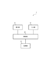
以下、図面を参照して実施の形態について説明する。図2は、実施の形態1にかかる表示装置1を示す図である。図2に示すように、表示装置1は、表示部12と、入力部14と、制御部20と、情報を記憶する記憶部16とから構成される。なお、以下、実質的に同じ構成要素には、同じ符号が付される。
[Embodiment 1]
Hereinafter, embodiments will be described with reference to the drawings. FIG. 2 is a diagram illustrating the display device 1 according to the first embodiment. As shown in FIG. 2, the display device 1 includes a
表示装置1は、例えば、スマートフォン、タブレット端末又はカーナビゲーション装置等のタッチスクリーン装置である。表示部12は、例えば、液晶ディスプレイ又はLEDディスプレイ等である。表示部12は、記憶部16に記憶されたコンテンツを表示するが、例えば、ストリーミング等によって、インターネット又はLAN(Local Area Network)等のネットワークを介して受信したコンテンツを表示してもよい。また、表示部12は、筐体の開口部から入力部14で覆われた状態で露出している。
The display device 1 is, for example, a touch screen device such as a smartphone, a tablet terminal, or a car navigation device. The
入力部14は、例えば、静電容量方式のタッチパネル等であって、操作体を入力部14に接触させることによって操作がなされる。ここで、操作体は、指又はタッチペン等であて、静電容量方式のタッチパネルの操作が可能である物体である。入力部14は、図3(A)に示すように、表示部12の表示面上に配置されている。つまり、入力部14と表示部12とが一体となってコンテンツを表示する画面を構成しており、使用者は、入力部14を介して、操作体を画面に接触させることができる。
The
なお、「画面」とは、表示装置1においてコンテンツが表示されている領域面をいう。また、「操作体が画面に接触する」とは、例えば、本実施の形態における表示装置1のように表示装置がタッチスクリーンである場合は、入力部14と表示部12とが一体となって構成された画面(入力部14の表面)に操作体が接触することである。言い換えれば、「操作体が入力部14に接触する」とは、(入力部14と表示部12とが一体となって構成された)画面に操作体が接触することである。また、表示装置がPC等のディスプレイの場合、「操作体が画面に接触する」とは、そのディスプレイの表面に操作体が接触することである。
The “screen” refers to an area surface where content is displayed on the display device 1. Further, “the operating body touches the screen” means that, for example, when the display device is a touch screen like the display device 1 in the present embodiment, the
制御部20は、例えば中央演算処理装置(CPU:Central Processing Unit)、メモリ及び入出力ポート等を含み、記憶部16に格納された各種プログラムを用いて各種制御を実行する。記憶部16は、例えばハードディスクであって、プログラム又はコンテンツ等の情報を記憶する。
The
表示装置1における操作について説明する。使用者が操作体を入力部14の所望の位置に接触させると、入力部14は、接触した点の座標情報(位置情報)を制御部20に出力する。制御部20は、記憶部16に格納されているプログラムに基づいて、予め定められた機能を実現すると共に、記憶部16に格納されている情報等を表示するために表示部12を制御する。具体的には、制御部20は、入力部14からの座標情報を受け付けると、その座標情報が表示部12に表示されているコンテンツのどの位置に対応するかを判断し、そのコンテンツの位置に対応する機能を実行する。
An operation in the display device 1 will be described. When the user brings the operating tool into contact with a desired position of the
ここで、操作体が画面に接触したか否かを検知する方法を説明する。静電容量方式においては、入力部14が、指等の操作体と入力部14(画面)との間に発生する静電容量を計測することによって、接触を検知する。指は導電性を有するので、指と入力部14との間で、静電容量が発生する。一般に、互いに平行な2枚の導体板の面積をS[m2]、2枚の導体板間の距離をD[m]、2枚の導体板間に充填された誘電体の誘電率をεとすると、その2枚の導体板間に発生する静電容量C[F]は、以下の式1で表される。
C=(ε*S)/D (式1)
Here, a method for detecting whether or not the operating tool has touched the screen will be described. In the capacitance method, the
C = (ε * S) / D (Formula 1)
式1に示すように、2枚の導体板間の距離が小さいほど、発生する静電容量の大きさは大きくなり、2枚の導体板間の距離が大きいほど、発生する静電容量の大きさは小さくなる。したがって、図3(A)において、操作体90と入力部14との距離Dが小さくなるほど(操作体90が入力部14に近づくほど)静電容量は大きくなる。
As shown in Equation 1, the smaller the distance between the two conductor plates, the larger the generated capacitance, and the larger the distance between the two conductor plates, the larger the generated capacitance. It gets smaller. Therefore, in FIG. 3A, the capacitance increases as the distance D between the operating
入力部14は、発生する静電容量を計測する。そして、図3(B)のように、操作体90が入力部14に限りなく近づいて距離Dが限りなく0に近くなると、計測された静電容量の値が予め定められた閾値Cth1(接触閾値Cth1)以上となる。そのとき、入力部14は、操作体90が入力部14に接触したとみなしてよいほど接近(接触)したと判断する。さらに、入力部14は、その接触閾値Cth1以上の静電容量が計測された位置を接触点とし、その接触点の座標情報を、制御部20に出力する。
The
なお、図3(C)のように、使用者が手袋を着けている場合、手袋が入力部14に接触しても、指は入力部14に接触することはできない。しかしながら、式1に示すように、指と入力部14とが接触していなくても、静電容量は発生する。そこで、接触閾値Cth1の値を下げることによって、手袋を着けていても、接触を感知することができる。このように、接触していない状態であっても、入力部14は、入力部14からある程度の間隔を空けて接近した操作体を検知することができる。このように、画面に接触していなくても操作体を検知する機能を、ホバリング機能という。
As shown in FIG. 3C, when the user is wearing gloves, even if the gloves contact the
ホバリング機能では、この「ある程度まで接近した」状態で発生する静電容量の閾値を、接近閾値Cth2(<Cth1)と予め定めることができる。つまり、計測された静電容量Cが、接触閾値Cth1よりも小さいが接近閾値Cth2以上である場合、操作体は、入力部14に接触していないが、ある程度の間隔を空けて接近した状態である。そのとき、入力部14は、操作体90が入力部14に、接触はしていないがある程度接近したと判断する。さらに、入力部14は、その接近閾値Cth2以上の静電容量が計測された位置を接近点とし、その接近点の座標情報を、制御部20に出力する。制御部20は、以下に説明するように、入力部14からの接触点及び接近点の座標情報に基づいて、操作体の表示部12に対する傾きを算出する。そして、制御部20は、その傾きに基づいて、表示部12における表示領域を移動させるように制御する。
In the hovering function, the threshold value of the capacitance generated in the “approached to some extent” state can be determined in advance as an approach threshold value Cth2 (<Cth1). That is, when the measured electrostatic capacitance C is smaller than the contact threshold Cth1 but greater than or equal to the approach threshold Cth2, the operating body is not in contact with the
図4は、図2に示した制御部20によって実現される各構成要素を示す図である。図5は、制御部20によってなされる処理を示すフローチャートである。また、図6〜図10は、制御部20によってなされる処理を説明するための図である。
図4に示すように、制御部20は、移動制御開始部202、接触領域検知制御部204、接触領域座標取得部206、中心算出部208、接近領域検知制御部214、接近領域座標取得部216、傾き算出部218、データ格納部220、変化検出部230、移動制御終了部232、差分算出部240、移動速度算出部242、移動方向算出部244、及び表示領域移動制御部246から構成される。
FIG. 4 is a diagram showing each component realized by the
As illustrated in FIG. 4, the
なお、制御部20が実現する各構成要素は、例えば、コンピュータである制御部20が備える演算装置(図示せず)の制御によって、プログラムを実行させることによって実現できる。より具体的には、制御部20は、記憶部16に格納されたプログラムをメモリ(図示せず)にロードし、演算装置の制御によってプログラムを実行して実現する。また、各構成要素は、プログラムによるソフトウェアで実現することに限ることなく、ハードウェア、ファームウェア、及びソフトウェアのうちのいずれかの組み合わせ等により実現してもよい。
In addition, each component which the
制御部20は、移動制御を開始するか否かを判断する(S102)。具体的には、移動制御開始部202は、入力部14に対して、コンテンツの表示領域の移動(スクロール操作)を開始させるための操作(移動開始操作)がなされたことを示す信号(開始信号)を受け付けたか否かを判断する。ここで、移動開始操作は、例えば、使用者が、操作体を入力部14に一定時間(例えば2秒)同じ位置に接触させる(長押し)操作であってもよい。また、移動開始操作は、例えば、画面の予め定められた位置(例えば右下)に操作体を接触させる(タップ)操作であってもよい。
The
制御部20が移動制御を開始すると判断した場合(S102のYES)、制御部20は、接触領域A1及び接近領域A2を取得する(S104)。具体的には、移動制御開始部202は、開始信号を受け付けると、まず、接触領域検知制御部204に対して、開始信号を出力する。ここで、接触領域A1とは、操作体が入力部14(画面)に接触したと判断された領域(座標群)である。また、接近領域A2とは、操作体が入力部14(画面)に接触はしていないがある程度まで接近したと判断された領域(座標群)である。
When it is determined that the
接触領域検知制御部204は、開始信号を受け付けると、入力部14に対し、接触閾値Cth1以上の静電容量を検出した位置、つまり、操作体が入力部14に接触した位置における座標情報を、制御部20に対して出力するように制御する。接触領域座標取得部206は、入力部14から、接触閾値Cth1以上の静電容量を検出した位置における座標情報(接触領域座標)を取得する。また、接触領域座標取得部206は、取得した接触領域座標を、データ格納部220に格納する。
When the contact area
例えば、図6(A)に例示するように、操作体90が入力部14に接触した場合、入力部14の表面(画面)からの距離がD1以内であるときに、入力部14は、接触閾値Cth1以上の静電容量を検出する。このとき、図6(B)に例示するように、入力部14は、接触閾値Cth1以上の静電容量が計測された接触点の座標として、(X2,Y2)、(X2,Y3)及び(X2,Y4)を検出する。入力部14は、これらの接触点の座標の集合を接触領域A1として、これらの座標情報(接触領域座標)を、制御部20に対して出力し、接触領域座標取得部206は、その接触領域座標を取得する。
For example, as illustrated in FIG. 6A, when the operating
接触領域座標取得部206が接触領域座標を受け付けると、次に、移動制御開始部202は、接近領域検知制御部214に対して、開始信号を出力する。接近領域検知制御部214は、開始信号を受け付けると、入力部14に対し、接触閾値Cth1よりも小さいが接近閾値Cth2以上の静電容量を検出した位置、つまり、操作体が入力部14に接近した位置における座標情報を、制御部20に対して出力するように制御する。接近領域座標取得部216は、入力部14から、接触閾値Cth1よりも小さいが接近閾値Cth2以上の静電容量を検出した位置における座標情報(接近領域座標)を取得する。また、接近領域座標取得部216は、取得した接近領域座標を、データ格納部220に格納する。
When the contact area coordinate
例えば、図6(A)に例示するように、操作体90が入力部14に接触した場合、入力部14の表面(画面)からの距離がD1よりも遠く且つD2以内である操作体90の一部90aは、入力部14に接触はしていないが、ある程度まで接近している。つまり、この操作体90の一部90aによって、接触閾値Cth1よりも小さいが接近閾値Cth2以上の静電容量が発生する。したがって、このとき、入力部14は、接触閾値Cth1よりも小さいが接近閾値Cth2以上の静電容量を検出する。
For example, as illustrated in FIG. 6A, when the operating
また、このとき、図6(B)に例示するように、入力部14は、接触閾値Cth1よりも小さいが接近閾値Cth2以上の静電容量が計測された接近点の座標として、(X3,Y2)、(X3,Y3)、(X3,Y4)、(X4,Y2)、(X4,Y3)、(X4,Y4)及び(X5,Y3)を検出する。入力部14は、これらの接近点の座標の集合を接近領域A2として、これらの座標情報(接近領域座標)を、制御部20に対して出力し、接近領域座標取得部216は、その接近領域座標を取得する。
At this time, as illustrated in FIG. 6B, the
次に、制御部20は、初期傾きベクトルB1を算出する(S106)。ここで、初期傾きベクトルとは、操作体が入力部14(画面)に接触し、操作体の傾きが変更される前の、操作体の傾きを示すベクトルである。この初期傾きベクトルは、以降の処理で、表示領域の移動速度及び移動方向を算出するための基準となるベクトルとなる。
Next, the
具体的な処理としては、まず、中心算出部208は、接触領域座標から、接触領域A1の中心の座標を算出する。具体的には、中心算出部208は、接触領域座標それぞれのX座標及びY座標について、それぞれの平均値を算出する。そして、中心算出部208は、X座標の平均値を中心点のX座標とし、Y座標の平均値を中心点のY座標とする。さらに、中心算出部208は、中心点の座標情報をデータ格納部220に格納する。
As a specific process, first, the
図6の例では、接触領域座標は(X2,Y2)、(X2,Y3)及び(X2,Y4)なので、接触領域A1の中心点の座標を(Xc,Yc)とすると、中心算出部208は、Xc=(X2+X2+X2)/3から、Xc(=X2)を算出する。さらに、中心算出部208は、Yc=(Y2+Y3+Y4)/3から、Yc(=Y3)を算出する。
In the example of FIG. 6, the contact area coordinates are (X2, Y2), (X2, Y3), and (X2, Y4). Therefore, if the coordinates of the center point of the contact area A1 are (Xc, Yc), the
傾き算出部218は、接近領域座標のうち、接触領域A1の中心点から最も遠い点を算出する。具体的には、傾き算出部218は、接触領域A1の中心点と接近領域座標の点それぞれとの距離を算出し、その距離が最も大きな接近領域座標の点を、接触領域A1の中心点から最も遠い点とする。そして、傾き算出部218は、接触領域A1の中心点を始点とし、その最も遠い点を終点とするベクトルを、操作体が入力部14(画面)に接触した当初の操作体の傾きを示す初期傾きベクトルB1として算出する。言い換えれば、傾き算出部218は、接触領域A1の中心点を始点とし、接近領域座標の各点を終点とするベクトルの内、ベクトルの長さ(スカラー量)が最大となるベクトルを、初期傾きベクトルB1として算出する。さらに、傾き算出部218は、初期傾きベクトルB1を示す情報を、データ格納部220に格納する。なお、スカラー量が最大のベクトルが複数ある場合、傾き算出部218は、それらのベクトルの平均を初期傾きベクトルB1として算出してもよい(以降のS120の処理における変化後傾きベクトルB2についても同様)。
The
図6の例では、接近領域座標(X3,Y2)、(X3,Y3)、(X3,Y4)、(X4,Y2)、(X4,Y3)、(X4,Y4)及び(X5,Y3)のうち、中心点(Xc,Yc)=(X2,Y3)から最も遠い点は(X5,Y3)である。したがって、図6(C)に例示するように、傾き算出部218は、中心点(Xc,Yc)=(X2,Y3)を始点とし、(X5,Y3)を終点とするベクトルを、初期傾きベクトルB1とする。
In the example of FIG. 6, the approach area coordinates (X3, Y2), (X3, Y3), (X3, Y4), (X4, Y2), (X4, Y3), (X4, Y4) and (X5, Y3) Among these, the point farthest from the center point (Xc, Yc) = (X2, Y3) is (X5, Y3). Therefore, as illustrated in FIG. 6C, the
初期傾きベクトルB1が算出されると、再び、制御部20は、接触領域A1及び接近領域A2を取得する(S108)。具体的には、接触領域検知制御部204は、再び、入力部14に対し、接触領域座標を制御部20に対して出力するように制御する。そして、接触領域座標取得部206は、再び、入力部14から接触領域座標を取得し、取得した接触領域座標を、データ格納部220に格納する。さらに、接近領域検知制御部214は、再び、入力部14に対し、接近領域座標を制御部20に対して出力するように制御する。そして、接近領域座標取得部216は、再び、入力部14から接近領域座標を取得し、取得した接近領域座標を、データ格納部220に格納する。このように、操作体が画面に接触し、表示領域の移動処理が開始すると、その間、接触領域A1及び接近領域A2を、常に検知することができる。
When the initial inclination vector B1 is calculated, the
制御部20は、接触領域A1が変化したか否かを判断する(S110)。具体的には、変化検出部230は、データ格納部220に格納された接触領域座標が変化したか否かを判断する。例えば、変化検出部230は、中心算出部208によって算出された中心点の座標が、S108の処理で取得された接触領域座標に含まれる場合は、接触領域A1が変化していないと判断する。一方、変化検出部230は、中心点の座標がS108の処理で取得された接触領域座標に含まれない場合は、接触領域A1が変化したと判断する。なお、変化検出部230は、接触領域A1を構成する接触領域座標が少しでも変化した場合に接触領域A1が変化したと判断してもよく、接触領域A1を構成する接触領域座標の内の予め定められた割合の座標が変化した場合に接触領域A1が変化したと判断してもよい。
The
図7を用いて具体例を挙げて説明する。図7(B)に例示するように、図6の場合と比較して、操作体90の接触面積が増加したため、接触領域座標が増加している。しかしながら、S106の処理で中心算出部208によって算出された中心点の座標(X2,Y3)が接触領域座標に含まれている。したがって、この例においては、変化検出部230は、接触領域A1が変化していないと判断する。このように、S106の処理で中心算出部208によって算出された中心点の座標(X2,Y3)が接触領域座標に含まれているか否かを判断基準とすることによって、操作体の傾きを変化させた場合に接触領域が多少ずれたとしても移動処理を継続することができる。
A specific example will be described with reference to FIG. As illustrated in FIG. 7B, the contact area coordinates are increased because the contact area of the operating
接触領域A1が変化したと判断された場合(S110のYES)、制御部20は、移動制御を終了する。具体的には、変化検出部230は、中心点の座標がS108の処理で取得された接触領域座標に含まれない場合、移動制御終了部232に対してその旨を示す信号を出力する。そのとき、移動制御終了部232は、コンテンツの表示領域の移動処理(スクロール操作)を終了する。中心点の座標が接触領域座標に含まれないなど、接触領域座標が変化した場合、使用者は、操作体を画面から離すなどし、スクロール操作の中止を所望している可能性が高いからである。
When it is determined that the contact area A1 has changed (YES in S110), the
一方、接触領域A1が変化していないと判断された場合(S110のNO)、制御部20は、接近領域A2が変化したか否かを判断する(S112)。具体的には、変化検出部230は、データ格納部220に格納された接近領域座標が変化したか否かを判断する。例えば、変化検出部230は、接近領域A2を構成する接近領域座標が少しでも変化した場合に、接近領域A2が変化したと判断する。なお、変化検出部230は、接近領域A2を構成する接近領域座標の内の一部の座標(例えば、中心点から遠い座標など、傾きベクトルに影響を及ぼすような座標)が変化した場合に接近領域A2が変化したと判断してもよい。
On the other hand, when it is determined that the contact area A1 has not changed (NO in S110), the
接近領域A2が変化していないと判断された場合(S112のNO)、制御部20の処理はS108に戻り、再び、制御部20は、接触領域A1及び接近領域A2を取得する(S108)。そして、制御部20は、接触領域A1の変化の有無の判断(S110)、及び接近領域A2の変化の有無の判断(S112)を繰り返す。
When it is determined that the approach area A2 has not changed (NO in S112), the process of the
一方、接近領域A2が変化したと判断された場合(S112のYES)、制御部20は、変化後の傾きベクトルB2を算出する(S120)。具体的には、変化検出部230は、接近領域座標が変化した場合に、傾き算出部218に対して信号を出力する。傾き算出部218は、その信号を受け付けると、変化後の接近領域座標のうち、接触領域A1の中心点(S106で算出されたもの)から最も遠い点を算出する。そして、傾き算出部218は、S106の処理と同様に、接触領域A1の中心点を始点とし、その最も遠い点を終点とするベクトルを算出する。このベクトルが、操作体の接触当初の傾きから操作体の傾きが変化した後の傾きを示す変化後傾きベクトルB2である。
On the other hand, when it is determined that the approach area A2 has changed (YES in S112), the
図7の例では、図7(A)に例示するように、操作体90は、入力部14(画面)に対して寝た状態となっている。つまり、入力部14に対する操作体90の傾きが、図6(A)の状態と比較して大きくなって(操作体90と入力部14との角度が小さくなって)いる。この場合、操作体90の上の部分(接触位置から遠い部分)が入力部14に近づく。したがって、図7(B)に例示するように、操作体90の傾きが大きくなると、接近領域A2は、中心点(Xc,Yc)=(X2,Y3)から離れる方向に伸びる。そして、変化後の接近領域座標のうち、中心点(Xc,Yc)=(X2,Y3)から最も遠い点は(X8,Y3)である。したがって、図7(C)に例示するように、傾き算出部218は、中心点(Xc,Yc)=(X2,Y3)を始点とし、(X8,Y3)を終点とするベクトルを、変化後傾きベクトルB2とする。
In the example of FIG. 7, as illustrated in FIG. 7A, the
このように、初期傾きベクトルB1及び変化後傾きベクトルB2のような傾きベクトルは、操作体が傾くほどその大きさ(スカラー量)は大きくなる。さらに、傾きベクトルの向きは、操作体が傾いている方向を示している。したがって、傾きベクトルは、操作体の傾きを示している。 Thus, the magnitudes (scalar amounts) of the inclination vectors such as the initial inclination vector B1 and the changed inclination vector B2 increase as the operating body is inclined. Furthermore, the direction of the inclination vector indicates the direction in which the operating body is inclined. Therefore, the inclination vector indicates the inclination of the operating body.
次に、制御部20は、初期傾きベクトルB1と変化後傾きベクトルB2との差分を示す差分ベクトルB3を算出する(S122)。具体的には、差分算出部240は、S106の処理で算出された初期傾きベクトルB1と、S120の処理で算出された変化後傾きベクトルB2との差を算出し、算出されたベクトルを、差分ベクトルB3とする。さらに具体的には、差分算出部240は、初期傾きベクトルB1の始点及び終点の座標から、初期傾きベクトルB1のX成分及びY成分をそれぞれ算出する。同様に、差分算出部240は、変化後傾きベクトルB2の始点及び終点の座標から、変化後傾きベクトルB2のX成分及びY成分をそれぞれ算出する。そして、差分算出部240は、変化後傾きベクトルB2のX成分から初期傾きベクトルB1のX成分を減算することによって、差分ベクトルB3のX成分を算出することができる。さらに、差分算出部240は、変化後傾きベクトルB2のY成分から初期傾きベクトルB1のY成分を減算することによって、差分ベクトルB3のY成分を算出することができる。
Next, the
図7の例では、図7(D)に例示するように、初期傾きベクトルB1のX成分は+3、変化後傾きベクトルB2のX成分は+6なので、差分ベクトルB3のX成分は、+3である。また、初期傾きベクトルB1のY成分及び変化後傾きベクトルB2のY成分はともに0なので、差分ベクトルB3のY成分は0である。よって、差分算出部240は、(X,Y)=(+3,0)の差分ベクトルB3を算出する。
In the example of FIG. 7, as illustrated in FIG. 7D, the X component of the initial gradient vector B1 is +3, and the X component of the post-change gradient vector B2 is +6. Therefore, the X component of the difference vector B3 is +3. . Further, since the Y component of the initial gradient vector B1 and the Y component of the post-change gradient vector B2 are both 0, the Y component of the difference vector B3 is 0. Therefore, the
次に、制御部20は、表示領域の移動速度及び移動方向を算出する(S124)。具体的には、移動速度算出部242は、表示領域の移動速度を算出し、算出された移動速度を、表示領域移動制御部246に対して出力する。また、移動方向算出部244は、表示領域の移動方向を算出し、算出された移動方向を、表示領域移動制御部246に対して出力する。移動方向算出部244は、差分ベクトルB3の向きから、表示領域の移動方向を算出する。つまり、移動方向算出部244は、差分ベクトルB3の向きを、表示領域の移動方向としてもよい。
Next, the
移動速度算出部242は、差分ベクトルB3のスカラー量から、表示領域の移動速度を算出する。例えば、移動速度算出部242は、以下の式(2)を用いて、移動速度Vを算出する。
V=(|B3|/E)*Vst (式2)
ここで、|B3|は、差分ベクトルB3のスカラー量である。また、Vstは、予め定められた標準速度である。標準速度とは、使用者が速くもなく遅くもないスクロール速度であると認識しうる速度であってもよい。また、Eは標準速度からの増減を決定するための係数であって、例えば、初期傾きベクトルB1から算出されてもよい。
The moving
V = (| B3 | / E) * Vst (Formula 2)
Here, | B3 | is the scalar quantity of the difference vector B3. Vst is a predetermined standard speed. The standard speed may be a speed at which the user can recognize that the scroll speed is neither fast nor slow. Further, E is a coefficient for determining increase / decrease from the standard speed, and may be calculated from, for example, the initial gradient vector B1.
具体的には、係数Eは、初期傾きベクトルB1のスカラー量の半分(つまりE=|B1|/2)としてもよい。このように定義することによって、差分ベクトルB3のスカラー量が初期傾きベクトルB1のスカラー量の半分となるように、操作体の傾きを変化させるようにすると、標準速度Vstでの移動(スクロール)が可能となる。また、この場合、図7の例では、差分ベクトルB3のスカラー量は3であり、初期傾きベクトルB1のスカラー量は3であるので、V=2Vstとなる。 Specifically, the coefficient E may be half of the scalar quantity of the initial gradient vector B1 (that is, E = | B1 | / 2). By defining in this way, when the inclination of the operating body is changed so that the scalar quantity of the difference vector B3 is half the scalar quantity of the initial inclination vector B1, the movement (scrolling) at the standard speed Vst is performed. It becomes possible. In this case, in the example of FIG. 7, the scalar quantity of the difference vector B3 is 3, and the scalar quantity of the initial gradient vector B1 is 3, so V = 2Vst.
なお、傾きベクトルのスカラー量の最大値は、入力部14(画面)の縦方向の長さ及び横方向の長さと、操作体の長さとに左右される。つまり、傾きベクトルのスカラー量は、操作体の長さ以下となる。また、操作体の長さが入力部14(画面)からはみ出すほどの長さであれば、操作体をいくら傾けても、差分ベクトルB3のX成分(横方向)は、入力部14(画面)の横方向の長さ以下となり、差分ベクトルB3のY成分(縦方向)は入力部14(画面)の縦方向の長さ以下となる。したがって、係数Eの値を、傾きベクトルのスカラー量の最大値から予め算出してもよい。例えば、係数Eの値を、傾きベクトルのスカラー量の最大値の1/2又は1/4としてもよい。 Note that the maximum value of the scalar amount of the inclination vector depends on the length in the vertical direction and the length in the horizontal direction of the input unit 14 (screen), and the length of the operation body. That is, the scalar quantity of the inclination vector is equal to or less than the length of the operating body. Further, if the length of the operating body is such that it protrudes from the input unit 14 (screen), the X component (horizontal direction) of the difference vector B3 is the input unit 14 (screen) no matter how much the operating body is tilted. The Y component (vertical direction) of the difference vector B3 is equal to or less than the vertical length of the input unit 14 (screen). Accordingly, the value of the coefficient E may be calculated in advance from the maximum value of the scalar quantity of the gradient vector. For example, the value of the coefficient E may be 1/2 or 1/4 of the maximum value of the scalar vector of the gradient vector.
また、係数E及び標準速度Vstは、使用者によって任意に調整され得るようにしてもよい。これによって、使用者は、操作体の変化の度合いと表示領域の移動速度との関係を任意に調整することができる。つまり、例えば、使用者が、操作体の傾きを少し変化させただけなのに移動速度が速いと感じる場合は、係数Eを大きくし、又は標準速度Vstを小さくすることができる。 Further, the coefficient E and the standard speed Vst may be arbitrarily adjusted by the user. Thus, the user can arbitrarily adjust the relationship between the degree of change of the operating tool and the moving speed of the display area. That is, for example, when the user feels that the moving speed is fast even though the inclination of the operating body is slightly changed, the coefficient E can be increased or the standard speed Vst can be decreased.
次に、制御部20は、表示部12に対し、表示領域を移動させるように制御する(S126)。具体的には、表示領域移動制御部246は、移動方向算出部244で算出された方向に、移動速度算出部242で算出された速度(V)で、表示領域を移動させるように、表示部12を制御する。これにより、例えば図7の例では、X方向の正方向に、V=(|B3|/(3/2))*Vst(=2Vst)の速度で、表示領域が移動する。つまり、コンテンツのX方向の正方向の部分が閲覧できるようになる。
Next, the
また、表示領域移動制御部246は、表示領域が移動されている際に、移動速度を表示する速度指示計を、表示部12に表示させるようにしてもよい。これによって、使用者は、現在の移動速度を確認できる。したがって、使用者は、操作体をどれだけ傾ければ所望の速度で表示領域が移動するかを把握することができ、操作体の傾きを変化させた場合にどれだけ移動速度が変化するかを確認することができる。
Further, the display area
さらに、図7の状態から、図8の状態に、操作体の傾きが変化したとする。図8(A)に例示するように、操作体90は、入力部14(画面)に対して起きた状態となっている。つまり、入力部14に対する操作体90の傾きが、図6(A)の状態と比較して小さくなって(操作体90と入力部14との角度が90度に近づいて)いる。この場合、操作体90の上の部分(接触位置から遠い部分)が入力部14から離れる。したがって、図8(B)に例示するように、操作体90の傾きが小さくなると、接近領域A2は、中心点(Xc,Yc)=(X2,Y3)の方向へと縮む。
Furthermore, suppose that the inclination of the operating body has changed from the state of FIG. 7 to the state of FIG. As illustrated in FIG. 8A, the
そして、変化後の接近領域座標のうち、中心点(Xc,Yc)=(X2,Y3)から最も遠い点は(X3,Y4)及び(X3,Y2)である。このとき、傾き算出部218は、中心点(Xc,Yc)=(X2,Y3)を始点とし(X3,Y4)を終点とするベクトルと、中心点(Xc,Yc)=(X2,Y3)を始点とし(X3,Y2)を終点とするベクトルとの平均となるベクトルを算出する。具体的には、各ベクトルのX成分及びY成分についてそれぞれ平均値を算出し、その平均値を各成分とするベクトルを、変化後傾きベクトルB2とする。その結果、図8(C)に例示するように、傾き算出部218は、中心点(Xc,Yc)=(X2,Y3)を始点とし、(X3,Y3)を終点とするベクトルを、変化後傾きベクトルB2とする。
Of the approach area coordinates after the change, the points farthest from the center point (Xc, Yc) = (X2, Y3) are (X3, Y4) and (X3, Y2). At this time, the
このとき、初期傾きベクトルB1のX成分は+3、変化後傾きベクトルB2のX成分は+1なので、差分ベクトルB3のX成分は、−2である。また、初期傾きベクトルB1のY成分及び変化後傾きベクトルB2のY成分はともに0なので、差分ベクトルB3のY成分は0である。よって、図8(D)に例示するように、差分算出部240は、(X,Y)=(−2,0)の差分ベクトルB3を算出する。さらに、上記の式2から、移動速度算出部242は、移動速度を、V=(2/(3/2))*Vst=4/3Vstと算出する。また、移動方向算出部244は、差分ベクトルB3の方向がX方向の負方向であることから、移動方向をX方向の負方向と算出する。したがって、表示領域移動制御部246は、X方向の負方向に、V=4/3Vstの速度で、表示領域を移動させる。つまり、表示領域の移動方向が、図7の状態から逆転する。このように、操作体の傾きを変化させるのみで、容易に表示領域の移動方向を変更することができる。
At this time, since the X component of the initial gradient vector B1 is +3 and the X component of the post-change gradient vector B2 is +1, the X component of the difference vector B3 is −2. Further, since the Y component of the initial gradient vector B1 and the Y component of the post-change gradient vector B2 are both 0, the Y component of the difference vector B3 is 0. Therefore, as illustrated in FIG. 8D, the
図9及び図10を用いて、X方向及びY方向の両方に(つまり斜めに)表示領域を移動させる例について説明する。図9(A)に例示するように、まず、操作体90の先端を入力部14に接触させる。このとき、図9(B)に例示するように、接触領域座標取得部206は、接触領域座標として点(X2,Y5)を取得する。したがって、中心算出部208は、(X2,Y5)を中心とする。また、接近領域座標取得部216は、接近領域座標として、(X2,Y1)、(X2,Y2)、(X2,Y3)及び(X2,Y4)を取得する。したがって、傾き算出部218は、中心点(X2,Y5)を始点とし、中心点から最も遠い点(X2,Y1)を終点とするベクトルを、初期傾きベクトルB1とする(S104,S106)。
An example in which the display area is moved in both the X direction and the Y direction (that is, obliquely) will be described with reference to FIGS. 9 and 10. As illustrated in FIG. 9A, first, the tip of the
さらに、図9の状態から、図10の状態に、操作体の傾きが変化したとする。図10(A)に例示するように、操作体90は、接触箇所を中心として反時計回りに回転するように移動している。このとき、図10(B)に例示するように、接触領域座標は(X2,Y5)なので、変化検出部230は、接触領域A1が変化していないと判断する。また、接近領域座標取得部216によって、接近領域座標として、(X3,Y4)、(X4,Y3)及び(X5,Y2)が取得されているので、変化検出部230は、接近領域A2が変化したと判断する(S110,S112)。
Furthermore, it is assumed that the tilt of the operating body has changed from the state of FIG. 9 to the state of FIG. As illustrated in FIG. 10A, the
変化後の接近領域座標のうち、中心点(Xc,Yc)=(X2,Y5)から最も遠い点は(X5,Y2)である。したがって、図10(C)に例示するように、傾き算出部218は、中心点(Xc,Yc)=(X2,Y5)を始点とし(X5,Y2)を終点とするベクトルを算出し、変化後傾きベクトルB2とする(S120)。
Of the approach region coordinates after the change, the point farthest from the center point (Xc, Yc) = (X2, Y5) is (X5, Y2). Therefore, as illustrated in FIG. 10C, the
さらに、初期傾きベクトルB1のX成分は0であり、変化後傾きベクトルB2のX成分は+3なので、差分ベクトルB3のX成分は、+3である。また、初期傾きベクトルB1のY成分は−4であり、変化後傾きベクトルB2のY成分は−3なので、差分ベクトルB3のY成分は+1である。よって、図10(D)に例示するように、差分算出部240は、(X,Y)=(+3,+1)の差分ベクトルB3を算出する。そして、表示領域移動制御部246は、この差分ベクトルB3のスカラー量に対応する移動速度で、この差分ベクトルB3の向きに、表示領域を移動させる。これにより、表示領域を斜め方向に移動させることができる。
Furthermore, since the X component of the initial gradient vector B1 is 0 and the X component of the post-change gradient vector B2 is +3, the X component of the difference vector B3 is +3. Further, since the Y component of the initial gradient vector B1 is −4 and the Y component of the post-change gradient vector B2 is −3, the Y component of the difference vector B3 is +1. Therefore, as illustrated in FIG. 10D, the
上述したように、実施の形態1においては、画面に接触させた操作体を傾けておくだけで、例えば、ジョイスティックを操作するように、連続的なスクロールを実行することができ、フリック操作のように何度も繰り返し行う必要がない。また、操作体の傾きを変更するだけで、表示領域の移動方向及び移動速度を、任意にかつ容易に変更することができる。 As described above, in the first embodiment, it is possible to execute continuous scrolling just by tilting the operating body that is in contact with the screen, for example, to operate a joystick. There is no need to repeat it over and over. In addition, the moving direction and moving speed of the display area can be arbitrarily and easily changed simply by changing the tilt of the operating tool.
また、操作体を、画面の任意の位置に接触させた状態で接触位置を維持した状態で、傾きを変化させるだけで表示領域の移動方向及び移動速度を任意に変更できるので、画面に表示されたコンテンツのうち最小限の箇所を覆い隠すのみとなる。したがって、コンテンツの閲覧性を向上させることができる。さらに、使用者は画面を見ながら操作体を傾けて表示領域を移動させることができるので、コンテンツの閲覧性を向上させることができる。 In addition, the moving direction and moving speed of the display area can be changed arbitrarily by simply changing the tilt while maintaining the contact position while the operating tool is in contact with any position on the screen. It will only cover the smallest part of the content. Therefore, it is possible to improve the viewability of the content. Furthermore, since the user can move the display area by tilting the operating body while looking at the screen, it is possible to improve the viewability of the content.
また、最初に操作体を接触させた状態において初期傾きベクトルB1を算出し、表示領域の移動速度及び移動方向の基準とすることによって、基準となる傾きを容易に設定することができる。ジョイスティックの場合は、一般的に垂直方向が基準となっているが、操作体が指の場合、爪があるために、意識的にでないと指を画面に垂直に立てることは困難である。しかしながら、実施の形態1においては、基準を任意に設定できるので、自然に指を画面に置いた状態を基準とすることができる。したがって、その状態から傾きを変化させることにより、自然な状態から移動速度及び移動方向を変更できる。 Further, by calculating the initial inclination vector B1 in a state where the operating body is first contacted and using it as a reference for the moving speed and moving direction of the display area, the reference inclination can be easily set. In the case of a joystick, the vertical direction is generally used as a reference. However, when the operating body is a finger, there is a nail, so it is difficult to stand the finger vertically on the screen unless it is conscious. However, in the first embodiment, since the reference can be arbitrarily set, the state where the finger is naturally placed on the screen can be used as the reference. Therefore, by changing the inclination from the state, the moving speed and the moving direction can be changed from the natural state.
[変形例]
なお、本発明は上記実施の形態に限られたものではなく、以下のように、趣旨を逸脱しない範囲で適宜変更することが可能である。例えば、操作体の例は、指に限られない。傾きを検知できる物体であれば何でもよい。また、上述した実施の形態1にかかる表示装置の構成部分を備えた各種の電子機器であってもよい。
[Modification]
Note that the present invention is not limited to the above-described embodiment, and can be modified as appropriate without departing from the spirit of the present invention. For example, the example of the operation body is not limited to the finger. Any object that can detect tilt can be used. Moreover, the various electronic devices provided with the component of the display apparatus concerning Embodiment 1 mentioned above may be sufficient.
また、上述した実施の形態1においては、表示領域を移動させるとしたが、コンテンツ自体を差分ベクトルの方向に移動させるようにしてもよい。このとき、表示領域は、差分ベクトルの方向とは逆方向に移動する。また、上述した実施の形態1においては、画面の横方向(X成分)及び縦方向(Y成分)それぞれについて計算を行うとしたが、画面の縦方向(Y方向)にのみスクロールするようなコンテンツの場合は、X成分を除外して計算してもよい。 In the first embodiment described above, the display area is moved, but the content itself may be moved in the direction of the difference vector. At this time, the display area moves in the direction opposite to the direction of the difference vector. In Embodiment 1 described above, the calculation is performed for each of the horizontal direction (X component) and the vertical direction (Y component) of the screen. However, content that scrolls only in the vertical direction (Y direction) of the screen. In the case of, calculation may be performed excluding the X component.
また、上述した実施の形態1においては、表示部12の上に入力部14が配置されるとしたが、表示部12と入力部14との関係は逆でもよい。つまり、入力部14の上に表示部12があってもよい。さらに、上述した実施の形態1においては、入力部14はタッチパネルとしたが、タッチパネルに限られない。また、上述した実施の形態1においては、操作体の傾きを検知する方法として、静電容量を検知するとしたが、静電容量によって傾きを検知しなくてもよい。
Moreover, in Embodiment 1 mentioned above, although the
例えば、操作体に装着可能な傾きセンサによって、操作体の傾きを検知してもよい。この場合、傾きセンサが入力部14となる。また、操作体と表示部(画面)との位置関係を測定するカメラによって、操作体の傾きを検知してもよい。この場合、カメラが入力部14となる。また、操作体と画面との距離(又は距離に応じて変化する物理量)を計測するセンサによって、操作体の傾きを検知してもよい。つまり、表示装置は、タッチスクリーン装置に限られず、例えばPCのディスプレイであってもよい。なお、静電容量によって傾きを検知することによって、元々備わっている入力部14を使用することによって傾きを検知できるので、上記のような装置が不要となる。
For example, the inclination of the operating body may be detected by an inclination sensor that can be attached to the operating body. In this case, the tilt sensor becomes the
なお、図5に示したフローチャートにおいて、処理(ステップ)の順序は、適宜、変更可能である。また、1つの処理(ステップ)が実行されている間に他の処理(ステップ)が実行されてもよい。また、複数ある処理(ステップ)のうちの1つ以上は、省略されてもよい。例えば、S112の処理はなくてもよく、A2が変更したか否かに関わらず、常に、差分ベクトルB3を算出するようにしてもよい。また、S106の処理が終了する前にS108の処理を開始してもよい。 In the flowchart shown in FIG. 5, the order of processing (steps) can be changed as appropriate. Further, another process (step) may be executed while one process (step) is being executed. One or more of the plurality of processes (steps) may be omitted. For example, the process of S112 may not be performed, and the difference vector B3 may always be calculated regardless of whether or not A2 is changed. Further, the process of S108 may be started before the process of S106 is completed.
1 表示装置
12 表示部
14 入力部
16 記憶部
20 制御部
202 移動制御開始部
204 接触領域検知制御部
206 接触領域座標取得部
208 中心算出部
214 接近領域検知制御部
216 接近領域座標取得部
218 傾き算出部
220 データ格納部
230 変化検出部
232 移動制御終了部
240 差分算出部
242 移動速度算出部
244 移動方向算出部
246 表示領域移動制御部
DESCRIPTION OF SYMBOLS 1
Claims (14)
コンテンツを画面に表示させる表示手段と、
当該表示装置とは別個の物体である操作体と前記画面との位置関係を検知する入力手段と、
前記入力手段によって検知された位置関係に基づいて算出された、前記操作体の前記画面に対する傾きに基づいて、前記コンテンツが表示される表示領域を移動させる制御手段と
を有する表示装置。 A display device,
Display means for displaying content on the screen;
Input means for detecting the positional relationship between the operation body, which is an object separate from the display device, and the screen;
And a control unit configured to move a display area in which the content is displayed based on an inclination of the operating body with respect to the screen calculated based on a positional relationship detected by the input unit.
請求項1に記載の表示装置。 The display device according to claim 1, wherein the control unit moves the display area of the content based on a change amount of the tilt of the operation body.
請求項2に記載の表示装置。 The control means maintains the screen of the operating body while maintaining the inclination of the operating body in the first state when the operating body touches the screen and the contact position of the operating body in the first state. The display device according to claim 2, wherein the display area of the content is moved based on a difference from the tilt of the operating body in the second state when the tilt with respect to is changed.
請求項2または3に記載の表示装置。 The display device according to claim 2, wherein the control unit changes a moving speed of a display area of the content based on the change amount.
請求項2から4のいずれか1項に記載の表示装置。 The display device according to claim 2, wherein the control unit changes a moving direction of the display area of the content based on the amount of change.
前記制御手段は、前記入力手段によって計測された前記物理量に基づいて、前記操作体の傾きを算出する
請求項1から5のいずれか1項に記載の表示装置。 The input means measures a physical quantity that changes in accordance with a distance between the operation body and the screen in association with a position of the screen,
The display device according to any one of claims 1 to 5, wherein the control unit calculates an inclination of the operation body based on the physical quantity measured by the input unit.
前記制御手段は、前記入力手段によって計測された前記静電容量に基づいて、前記操作体の傾きを算出する
請求項6に記載の表示装置。 The input means measures a capacitance generated by the operation body approaching the screen in association with a position of the screen;
The display device according to claim 6, wherein the control unit calculates an inclination of the operation body based on the capacitance measured by the input unit.
請求項7に記載の表示装置。 The control means detects, on the screen, a region including a position where the capacitance is equal to or greater than a first threshold as a first region where the operating body is in contact with the screen, and the capacitance is A region that includes a position that is smaller than the first threshold and greater than a second threshold that is smaller than the first threshold, but the operating body is not touching the screen but is approaching the second The display device according to claim 7, wherein the display device is detected as an area, and an inclination of the operating body is detected based on the first area and the second area.
請求項8に記載の表示装置。 The control means is based on a first vector starting from the center of the first region and ending at a point farthest from the center of the first region in the second region. The display device according to claim 8, wherein inclination is detected.
請求項9に記載の表示装置。 The control means calculates a second vector indicating a difference between the first vectors when the tilt of the operating body changes, and based on the second vector, the moving speed of the content display area and The display device according to claim 9, wherein the moving direction is calculated.
請求項1から10のいずれか1項に記載の表示装置。 The display device according to claim 1, wherein the control unit causes the display unit to display a moving speed meter indicating a moving speed of the display area during movement of the display area of the content.
コンテンツを画面に表示させる表示手段と、
当該電子機器とは別個の物体である操作体と前記画面との位置関係を検知する入力手段と、
前記入力手段によって検知された位置関係に基づいて算出された、前記操作体の前記画面に対する傾きに基づいて、前記コンテンツが表示される表示領域を移動させる制御手段と
を有する電子機器。 Electronic equipment,
Display means for displaying content on the screen;
Input means for detecting a positional relationship between the operation body, which is an object separate from the electronic device, and the screen;
An electronic device comprising: control means for moving a display area in which the content is displayed based on an inclination of the operating body with respect to the screen calculated based on a positional relationship detected by the input means.
前記表示装置とは別個の物体である操作体と前記画面との位置関係を検知する第1のステップと、
前記第1のステップにおいて検知された位置関係に基づいて、前記操作体の前記画面に対する傾きを算出する第2のステップと、
前記第2のステップにおいて算出された傾きに基づいて、前記コンテンツが表示される表示領域を移動させる第3のステップと
を含む表示方法。 A display method in a display device for displaying content on a screen,
A first step of detecting a positional relationship between the operating body, which is an object separate from the display device, and the screen;
A second step of calculating an inclination of the operating body with respect to the screen based on the positional relationship detected in the first step;
And a third step of moving a display area in which the content is displayed based on the inclination calculated in the second step.
前記表示装置とは別個の物体である操作体と前記画面との位置関係を取得する第1のステップと、
前記第1のステップにおいて取得された位置関係に基づいて、前記操作体の前記画面に対する傾きを算出する第2のステップと、
前記第2のステップにおいて算出された傾きに基づいて、前記コンテンツが表示される表示領域を移動させる第3のステップと
を前記表示装置のコンピュータに実行させるプログラム。 A program executed by a display device that displays content on a screen,
A first step of acquiring a positional relationship between the operation body, which is an object separate from the display device, and the screen;
A second step of calculating an inclination of the operating body with respect to the screen based on the positional relationship acquired in the first step;
A program for causing a computer of the display device to execute a third step of moving a display area in which the content is displayed based on the inclination calculated in the second step.
Priority Applications (1)
| Application Number | Priority Date | Filing Date | Title |
|---|---|---|---|
| JP2013026671A JP6119291B2 (en) | 2013-02-14 | 2013-02-14 | Display device, electronic device, display method, and program |
Applications Claiming Priority (1)
| Application Number | Priority Date | Filing Date | Title |
|---|---|---|---|
| JP2013026671A JP6119291B2 (en) | 2013-02-14 | 2013-02-14 | Display device, electronic device, display method, and program |
Publications (2)
| Publication Number | Publication Date |
|---|---|
| JP2014157402A true JP2014157402A (en) | 2014-08-28 |
| JP6119291B2 JP6119291B2 (en) | 2017-04-26 |
Family
ID=51578256
Family Applications (1)
| Application Number | Title | Priority Date | Filing Date |
|---|---|---|---|
| JP2013026671A Active JP6119291B2 (en) | 2013-02-14 | 2013-02-14 | Display device, electronic device, display method, and program |
Country Status (1)
| Country | Link |
|---|---|
| JP (1) | JP6119291B2 (en) |
Cited By (2)
| Publication number | Priority date | Publication date | Assignee | Title |
|---|---|---|---|---|
| JP2016157303A (en) * | 2015-02-25 | 2016-09-01 | 京セラ株式会社 | Electronic apparatus |
| WO2019188031A1 (en) * | 2018-03-29 | 2019-10-03 | 株式会社コナミデジタルエンタテインメント | Information processing device, and recording medium having program for information processing device recorded thereto |
Citations (8)
| Publication number | Priority date | Publication date | Assignee | Title |
|---|---|---|---|---|
| JPH0367320A (en) * | 1989-05-01 | 1991-03-22 | Wacom Co Ltd | Angle information input device |
| JP2004206613A (en) * | 2002-12-26 | 2004-07-22 | Wacom Co Ltd | Input device and input system |
| JP2008217790A (en) * | 2007-03-02 | 2008-09-18 | Lg Electronics Inc | Terminal and method for displaying information |
| JP2010140321A (en) * | 2008-12-12 | 2010-06-24 | Sony Corp | Information processing apparatus, information processing method, and program |
| JP2010277197A (en) * | 2009-05-26 | 2010-12-09 | Sony Corp | Information processing device, information processing method, and program |
| JP2011008424A (en) * | 2009-06-24 | 2011-01-13 | Sharp Corp | Electronic device, operation mode setting method, and program |
| JP2011186880A (en) * | 2010-03-10 | 2011-09-22 | Panasonic Corp | Coordinate input device and coordinate input method |
| JP2013065061A (en) * | 2011-09-15 | 2013-04-11 | Funai Electric Co Ltd | Projector |
-
2013
- 2013-02-14 JP JP2013026671A patent/JP6119291B2/en active Active
Patent Citations (8)
| Publication number | Priority date | Publication date | Assignee | Title |
|---|---|---|---|---|
| JPH0367320A (en) * | 1989-05-01 | 1991-03-22 | Wacom Co Ltd | Angle information input device |
| JP2004206613A (en) * | 2002-12-26 | 2004-07-22 | Wacom Co Ltd | Input device and input system |
| JP2008217790A (en) * | 2007-03-02 | 2008-09-18 | Lg Electronics Inc | Terminal and method for displaying information |
| JP2010140321A (en) * | 2008-12-12 | 2010-06-24 | Sony Corp | Information processing apparatus, information processing method, and program |
| JP2010277197A (en) * | 2009-05-26 | 2010-12-09 | Sony Corp | Information processing device, information processing method, and program |
| JP2011008424A (en) * | 2009-06-24 | 2011-01-13 | Sharp Corp | Electronic device, operation mode setting method, and program |
| JP2011186880A (en) * | 2010-03-10 | 2011-09-22 | Panasonic Corp | Coordinate input device and coordinate input method |
| JP2013065061A (en) * | 2011-09-15 | 2013-04-11 | Funai Electric Co Ltd | Projector |
Cited By (3)
| Publication number | Priority date | Publication date | Assignee | Title |
|---|---|---|---|---|
| JP2016157303A (en) * | 2015-02-25 | 2016-09-01 | 京セラ株式会社 | Electronic apparatus |
| WO2019188031A1 (en) * | 2018-03-29 | 2019-10-03 | 株式会社コナミデジタルエンタテインメント | Information processing device, and recording medium having program for information processing device recorded thereto |
| JP2019175239A (en) * | 2018-03-29 | 2019-10-10 | 株式会社コナミデジタルエンタテインメント | Program and information processing apparatus |
Also Published As
| Publication number | Publication date |
|---|---|
| JP6119291B2 (en) | 2017-04-26 |
Similar Documents
| Publication | Publication Date | Title |
|---|---|---|
| CN105339863B (en) | Mancarried device and its control method | |
| US8139028B2 (en) | Proximity sensor and method for indicating extended interface results | |
| JP5759660B2 (en) | Portable information terminal having touch screen and input method | |
| US8976140B2 (en) | Touch input processor, information processor, and touch input control method | |
| KR101062594B1 (en) | Touch screen with pointer display | |
| JP5999830B2 (en) | Information processing program, information processing apparatus, information processing system, and information processing method | |
| TW201329835A (en) | Display control device, display control method, and computer program | |
| JP2014203183A (en) | Information processing device and program | |
| JP5780438B2 (en) | Electronic device, position designation method and program | |
| KR20120023867A (en) | Mobile terminal having touch screen and method for displaying contents thereof | |
| US9268362B2 (en) | Method for controlling cursor | |
| JP5968588B2 (en) | Electronics | |
| WO2014083929A1 (en) | Method, device, and computer for document scrolling in touch panel | |
| JP5845585B2 (en) | Information processing device | |
| JP6119291B2 (en) | Display device, electronic device, display method, and program | |
| TWI536249B (en) | Hand-held touch device and its single-hand manipulation of the full touch range method | |
| KR20150122021A (en) | A method for adjusting moving direction of displaying object and a terminal thereof | |
| TWI439922B (en) | Handheld electronic apparatus and control method thereof | |
| JP6331022B2 (en) | Display device, display control method, and display control program | |
| KR20100058250A (en) | User interface of mobile device | |
| JP6106973B2 (en) | Information processing apparatus and program | |
| US11893229B2 (en) | Portable electronic device and one-hand touch operation method thereof | |
| KR20140088487A (en) | Terminal and method for controlling thereof | |
| JP2015005164A (en) | Touch panel device and display device | |
| JP2013235355A (en) | Display device, scrolling method and program |
Legal Events
| Date | Code | Title | Description |
|---|---|---|---|
| A711 | Notification of change in applicant |
Free format text: JAPANESE INTERMEDIATE CODE: A711 Effective date: 20150612 |
|
| A621 | Written request for application examination |
Free format text: JAPANESE INTERMEDIATE CODE: A621 Effective date: 20160113 |
|
| A977 | Report on retrieval |
Free format text: JAPANESE INTERMEDIATE CODE: A971007 Effective date: 20161026 |
|
| A131 | Notification of reasons for refusal |
Free format text: JAPANESE INTERMEDIATE CODE: A131 Effective date: 20161101 |
|
| A521 | Request for written amendment filed |
Free format text: JAPANESE INTERMEDIATE CODE: A523 Effective date: 20161226 |
|
| TRDD | Decision of grant or rejection written | ||
| A01 | Written decision to grant a patent or to grant a registration (utility model) |
Free format text: JAPANESE INTERMEDIATE CODE: A01 Effective date: 20170228 |
|
| A61 | First payment of annual fees (during grant procedure) |
Free format text: JAPANESE INTERMEDIATE CODE: A61 Effective date: 20170313 |
|
| R150 | Certificate of patent or registration of utility model |
Ref document number: 6119291 Country of ref document: JP Free format text: JAPANESE INTERMEDIATE CODE: R150 |