JP2014153776A - Information processing system, information processor, and control method and program therefor - Google Patents
Information processing system, information processor, and control method and program therefor Download PDFInfo
- Publication number
- JP2014153776A JP2014153776A JP2013020830A JP2013020830A JP2014153776A JP 2014153776 A JP2014153776 A JP 2014153776A JP 2013020830 A JP2013020830 A JP 2013020830A JP 2013020830 A JP2013020830 A JP 2013020830A JP 2014153776 A JP2014153776 A JP 2014153776A
- Authority
- JP
- Japan
- Prior art keywords
- information processing
- processing apparatus
- image display
- information
- display information
- Prior art date
- Legal status (The legal status is an assumption and is not a legal conclusion. Google has not performed a legal analysis and makes no representation as to the accuracy of the status listed.)
- Pending
Links
Images


Classifications
-
- G—PHYSICS
- G06—COMPUTING; CALCULATING OR COUNTING
- G06F—ELECTRIC DIGITAL DATA PROCESSING
- G06F3/00—Input arrangements for transferring data to be processed into a form capable of being handled by the computer; Output arrangements for transferring data from processing unit to output unit, e.g. interface arrangements
- G06F3/01—Input arrangements or combined input and output arrangements for interaction between user and computer
- G06F3/048—Interaction techniques based on graphical user interfaces [GUI]
- G06F3/0481—Interaction techniques based on graphical user interfaces [GUI] based on specific properties of the displayed interaction object or a metaphor-based environment, e.g. interaction with desktop elements like windows or icons, or assisted by a cursor's changing behaviour or appearance
- G06F3/04812—Interaction techniques based on cursor appearance or behaviour, e.g. being affected by the presence of displayed objects
-
- G—PHYSICS
- G06—COMPUTING; CALCULATING OR COUNTING
- G06F—ELECTRIC DIGITAL DATA PROCESSING
- G06F2203/00—Indexing scheme relating to G06F3/00 - G06F3/048
- G06F2203/038—Indexing scheme relating to G06F3/038
- G06F2203/0383—Remote input, i.e. interface arrangements in which the signals generated by a pointing device are transmitted to a PC at a remote location, e.g. to a PC in a LAN
Abstract
Description
本発明は、遠隔地から操作手順などを指示する技術に関するものである。 The present invention relates to a technique for instructing an operation procedure or the like from a remote place.
製品の使い方やトラブル対応の処置が複雑になるにつれ、顧客が直接メーカのコールセンタに電話して質問し、使い方やトラブルの対処方法等に関する回答を得るということが頻繁に行われている。このようなトラブル等に対する処置を適切かつ迅速に行うために、遠隔地から操作者の端末に直接ログインし、操作者の環境の設定を変更して支援するシステムが考えられている(例えば、特許文献1参照)。 As the use of products and troubleshooting procedures become more complex, customers frequently call the manufacturer's call center to ask questions and get answers on how to use and troubleshoot. In order to appropriately and quickly take measures against such troubles, a system is considered in which a user directly logs in to the operator's terminal from a remote location and changes the setting of the operator's environment (for example, a patent). Reference 1).
また最近では、VNC(Virtual Network Computing)を利用し、あるコンピュータのデスクトップ画面を、ネットワークを介して他のコンピュータに表示させて操作することが可能になっている。この技術を利用して、例えば、コールセンタのオペレータが、顧客の装置を遠隔操作し、その装置の保守や、操作者の操作を支援することが可能になる。また、コールセンタのオペレータが顧客の装置を遠隔操作し、操作した軌跡をカーソル等で示すことにより、その顧客に、その装置の操作手順を分かりやすく説明することができる。 Recently, it has become possible to display and operate a desktop screen of a certain computer on another computer via a network using VNC (Virtual Network Computing). By using this technology, for example, an operator of a call center can remotely operate a customer's device and support maintenance of the device and operation of the operator. Further, by operating the customer's device remotely by the call center operator and showing the operated locus with a cursor or the like, the customer can easily explain the operation procedure of the device.
しかし、画像処理装置などの常時カーソルを表示しない情報処理装置の場合に、遠隔地から、その装置の操作方法や設定方法等を説明する場合、どのボタンを押して操作を行っているか操作者に分かりにくいため、操作手順が正しく伝わらない可能性がある。 However, in the case of an information processing device that does not always display a cursor, such as an image processing device, when explaining the operation method or setting method of the device from a remote location, the operator knows which button is pressed to perform the operation. Because it is difficult, the operation procedure may not be transmitted correctly.
本発明の目的は、上記従来技術の問題点を解決することにある。 An object of the present invention is to solve the above-mentioned problems of the prior art.
本発明の特徴は、常時カーソルを表示しない情報処理装置に対しても、その情報処理装置の操作者に対して、カーソルを用いて操作した軌跡を示しながら、その装置の操作方法や設定方法等を説明する技術を提供することにある。 A feature of the present invention is that an information processing apparatus that does not always display a cursor, the operation method of the apparatus, a setting method, etc. while showing the locus operated using the cursor to the operator of the information processing apparatus It is to provide a technique for explaining the above.
上記目的を達成するために本発明の一態様に係る情報処理システムは以下のような構成を備える。即ち、
画像表示情報を配信する第1の情報処理装置と、前記画像表示情報を受信して表示する第2の情報処理装置とを有する情報処理システムであって、
前記第1の情報処理装置は、
前記第2の情報処理装置からの接続の要求を受信すると、前記第1の情報処理装置で表示する画像表示情報にカーソルのイメージを合成して記憶する記憶手段と、
前記第2の情報処理装置からの入力イベントを受信すると、前記入力イベントに基づいて前記記憶手段に記憶している画像表示情報を更新する更新手段と、
前記画像表示情報を前記第2の情報処理装置に送信する送信手段と、
前記記憶手段に記憶している前記画像表示情報を表示する表示手段とを有し、
前記第2の情報処理装置は、
ユーザの操作による入力イベントを前記第1の情報処理装置に送信する手段と、
前記第1の情報処理装置から送信される前記画像表示情報を受信して表示部に表示する制御手段と、を有することを特徴とする。
In order to achieve the above object, an information processing system according to an aspect of the present invention has the following arrangement. That is,
An information processing system comprising: a first information processing device that distributes image display information; and a second information processing device that receives and displays the image display information,
The first information processing apparatus includes:
A storage unit that, upon receiving a connection request from the second information processing apparatus, synthesizes and stores an image of a cursor on the image display information displayed on the first information processing apparatus;
An update means for updating the image display information stored in the storage means based on the input event when receiving an input event from the second information processing apparatus;
Transmitting means for transmitting the image display information to the second information processing apparatus;
Display means for displaying the image display information stored in the storage means,
The second information processing apparatus
Means for transmitting an input event by a user operation to the first information processing apparatus;
And control means for receiving the image display information transmitted from the first information processing apparatus and displaying the image display information on a display unit.
本発明によれば、常時カーソルを表示しない情報処理装置に対しても、その情報処理装置の操作者に対して、カーソルを用いて操作した軌跡を示しながら、その装置の操作方法や設定方法等を説明することができるという効果がある。 According to the present invention, even for an information processing apparatus that does not always display a cursor, an operation method, a setting method, and the like of the apparatus are shown while showing a trajectory operated using the cursor to an operator of the information processing apparatus. There is an effect that can be explained.
以下、添付図面を参照して本発明の実施形態を詳しく説明する。尚、以下の実施形態は特許請求の範囲に係る本発明を限定するものでなく、また本実施形態で説明されている特徴の組み合わせの全てが本発明の解決手段に必須のものとは限らない。 Hereinafter, embodiments of the present invention will be described in detail with reference to the accompanying drawings. The following embodiments do not limit the present invention according to the claims, and all combinations of features described in the embodiments are not necessarily essential to the solution means of the present invention. .
図1は、本発明の実施形態に係る情報処理システムの全体図である。 FIG. 1 is an overall view of an information processing system according to an embodiment of the present invention.
図1において、画像処理装置101は、LAN102を介してクライアント端末103と接続している。また画像処理装置101は、情報処理装置としてのサーバ(VRAMの内容を送り出す側)として機能しており、またクライアント端末103がクライアント、即ち、画像処理装置101のVRAM(ビデオメモリ)の内容を受信して表示する。
In FIG. 1, an
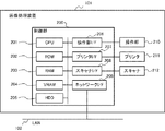
図2は、本発明の実施形態に係る画像処理装置101のハードウェア構成を示すブロック図である。
FIG. 2 is a block diagram showing a hardware configuration of the
CPU201を含む制御部200は、画像処理装置101全体の動作を制御する。CPU201は、ROM202に記憶されたブートプログラムにより、HDD205にインストールされているOSや制御プログラムを読み出してRAM203に展開し、その展開されたプログラムに従って読取制御や送信制御などの各種制御を行う。RAM203は、CPU201の主メモリ、ワークエリア等の一時記憶領域として用いられる。またRAM203は、仮想VRAMとして、画面表示用情報を一時保持する記憶領域としても用いられる。VRAM204は、RAM203の仮想VRAM領域から書き込まれる画面表示用情報を保持する記憶領域である。尚、RAM203の一部の領域をVRAM204として使用しても良い。HDD(ハードディスクドライブ)205は、画像データや各種プログラム、或いは各種情報テーブルを記憶する。
A
操作部I/F206は、操作部210と制御部200とを接続する。操作部210には、タッチパネル機能を有する表示部やキーボードなどが備えられている。また操作部210は、VRAM204に保持されている画像表示情報を基に表示部に画像を表示する。プリンタI/F207は、プリンタ211と制御部200とを接続する。プリンタ211で印刷すべき画像データは、プリンタI/F207を介して制御部200からプリンタ211に転送され、プリンタ211により記録媒体(シート)に印刷される。スキャナI/F208は、スキャナ212と制御部200とを接続する。スキャナ212は、原稿上の画像を読み取って画像データを生成し、その画像データをスキャナI/F208を介して制御部200に入力する。ネットワークI/F209は、制御部200をLAN102に接続する。ネットワークI/F209は、LAN102上の外部装置に画像データや情報を送信したり、LAN102上の外部装置から各種情報を受信する。
The operation unit I / F 206 connects the
図3は、本実施形態に係る画像処理装置101のソフトウェア構成を示すブロック図である。尚、図3に示す各部は、画像処理装置101に備えられているCPU201が、HDD203に格納された制御プログラムをRAM203に読み出して実行することにより実現される。
FIG. 3 is a block diagram showing a software configuration of the
画像処理装置101は、入力イベント受信部301、入力イベント作成部302、画像データ作成部303、画像データ送信部304を備えている。入力イベント受信部301では、CPU201は、クライアント端末103から送信された入力イベント信号を、LAN102を介して受信してRAM203に保持する。入力イベント作成部302では、CPU201は、入力イベント受信部301で受信した入力イベント信号に基づいて、画像処理装置101に対する入力イベント信号を生成して画像データ作成部303に送る。画像データ作成部303では、CPU201は、入力イベント信号を受け取ると、その内容を反映した画像表示情報を作成し、RAM203の仮想VRAM領域に保持する。画像データ送信部304では、CPU201は、RAM203の仮想VRAM領域に保持された画像表示情報を、LAN102を介してクライアント端末103に送信する。尚、RAM203の仮想VRAM領域から書き込まれたVRAM204に保持する画像表示情報を、クライアント端末103に送信してもよい。
The
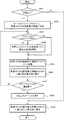
図4は、本発明の実施形態に係る画像処理装置101の処理を説明するフローチャートである。この処理は、画像処理装置101がクライアント端末103に画像表示情報を配信しているときに、画像処理装置101が、カーソルを合成して操作部210に表示するものである。図4のフローチャートに示す各ステップは、画像処理装置101のCPU201が、ROM202或いはHDD205に格納されている制御プログラムをRAM203に読み出して実行することにより実現される。
FIG. 4 is a flowchart for explaining processing of the
この処理はクライアント端末103からの入力イベントがあることにより開始される。まずS401で、CPU201は、クライアント端末103からの接続要求を受信したか否かを判定する。CPU201が、クライアント端末103からの接続要求を受信していると判定した場合はS402に進むが、そうでないときはS409に進む。
This process is started when there is an input event from the
S402では、CPU201は、ROM202もしくはHDD205に記憶されているカーソルのイメージをRAM203に読み込む。そしてCPU201は、RAM203の仮想VRAM領域が保持する画像表示情報に、そのカーソルのイメージを合成して、仮想VRAM領域に記憶する。次にS403に進み、CPU201は、クライアント端末103から送信される入力イベントを受信したか否かを判定する。具体的には、入力イベント受信部301は、クライアント端末103からLAN102を介して送信される入力イベント信号を受信したか否かを判定する。例えば、クライアント端末103で、ポインティングデバイスによるクリックや移動が行われると、クライアント端末103は、そのクリックや移動の情報と共に、その指示された座標を入力イベントとして画像処理装置101に送信する。これにより、画像処理装置101は、その入力イベントを受信することになる。S403で、CPU201が、入力イベントを受信していると判定した場合はS404に進むが、CPU201が、入力イベントを受信していないと判定した場合はS405に進む。
In step S <b> 402, the
S404では、CPU201は、受信した入力イベントを処理して画像表示情報を更新する。具体的には、入力イベント作成部302は、受信した入力イベント信号に基づいて、画像処理装置101に対する入力イベント信号を生成して画像データ作成部303に送る。これにより画像データ作成部303は、その入力イベントを実行した後の内容を反映した画像表示情報を作成し、RAM203の仮想VRAM領域に保持する。例えば、受信した入力イベントがポインティングデバイスの移動である場合、画像データ作成部303は、その移動の情報と共に、その受信した座標を基に、カーソルの位置を変更して(カーソルを移動して)画像表示情報を作成する。
In step S404, the
次にS405に進み、CPU201は、RAM203の仮想VRAM領域が保持する画像表示情報をクライアント端末103に送信する。これによりクライアント端末103は、その受信した画像表示情報を保持し、クライアント端末103の表示部に表示する。次にS406に進み、CPU201は、RAM203の仮想VRAM領域が保持する画像表示情報をVRAM204に書き込み、操作部I/F206を介して操作部210の表示部に表示する。ここでは、S402で、画像表示情報にカーソルを合成したデータを仮想VRAM領域に記憶しているため、CPU201は、画像表示情報にカーソルを表示した状態で出力する。
In step S <b> 405, the
次にS407に進み、CPU201は、クライアント端末103との接続が切断されたか否かを判定する。CPU201が、クライアント端末103からの接続が切断されたと判定した場合はS408に進む。CPU201が、クライアント端末103からの接続が切断されていない判断した場合はS403に戻る。S408では、CPU201は、画像表示情報に合成されているカーソルの表示をやめる。具体的には、CPU201は、S402でRAM203にロードしたカーソルのイメージを消去する。そしてS409に進み、CPU201は、RAM203の仮想VRAM領域が保持する画像表示情報をVRAM204に書き込み、操作部I/F206を介して操作部210の表示部に表示する。S409では、画像表示情報にカーソルを合成せずに仮想VRAM領域に記憶しているため、CPU201は、画像表示情報にカーソルを表示しない状態で表示する。
In step S407, the
このような処理を実行することにより、クライアント端末103にカーソルを含む画像表示情報を送信して、クライアント端末103の画面に表示することができる。これにより、カーソルを表示しない画像処理装置101の操作者に対して、クライアント端末103からカーソルを用いて操作した軌跡を示しながら、その装置の操作方法や設定方法等を説明することができるようになる。
By executing such processing, image display information including a cursor can be transmitted to the
図5は、本実施形態に係る画像処理装置101が記憶する画像表示情報を操作部210の表示部に表示した例を示す図である。
FIG. 5 is a diagram illustrating an example in which image display information stored in the
図5(A)は、画像処理装置101がクライアント端末103と接続されていない状態のときに、操作部210に表示される画面例を示す。即ち、図5(A)は、図4のS409で画像表示情報を操作部210に出力した状態を示す。この画面は、画像処理装置101が持つ様々な機能をユーザに選択、指示させるための画面である。この状態で、遠隔地のコールセンタから操作手順を説明する場合、何のボタンを押して操作を行っているか、操作者に分かりにくいため、操作手順が正しく伝わらない可能性がある。
FIG. 5A shows an example of a screen displayed on the
これに対して図5(B)は、画像処理装置101がクライアント端末103と接続されている状態のときに、操作部210に表示される画面例を示す。即ち、図5(B)は、図4のS406で、画像表示情報を操作部210の表示部に表示した状態を示す。カーソル502は、クライアント端末103からの入力イベントに応じて移動するオブジェクトである。
On the other hand, FIG. 5B shows an example of a screen displayed on the
これにより、遠隔地のコールセンタ(クライアント端末)から画像処理装置101の操作手順を説明する場合に、コールセンタのオペレータが操作した軌跡がカーソル502を通じて画像処理装置101の表示部に表示される。このため、画像処理装置101の操作者にとって操作手順が分かりやすく、正しい操作手順を伝えることができる。
As a result, when the operation procedure of the
尚、本実施形態では、画像処理装置101(第1の情報処理装置)がクライアント端末103(第2の情報処理装置)と接続された際に、画像処理装置101にカーソル502を表示する場合で説明した。しかしながら、クライアント端末103と接続された際に、画像処理装置101でカーソル502を表示させないように設定するようにしても良い。また例えば、画像処理装置101或いはクライアント端末103で、ユーザに、VNC接続時にカーソルを表示するかしないかを選択させるようにしても良い。
In the present embodiment, the
またクライアント端末103、或いは画像処理装置101で、カーソルを表示するかしないかを設定できるようにしても良い。
In addition, the
また、VNC接続時に、マウスカーソルを表示するが、S−Mode等の、特定のモードの場合には、マウスカーソルを表示しないようにしても良い。 In addition, the mouse cursor is displayed when the VNC is connected, but the mouse cursor may not be displayed in a specific mode such as S-Mode.
また本実施形態では、画像処理装置101がクライアント端末103と接続された際は、常時、画像処理装置101でカーソル502を表示する場合で説明した。しかし、例えば特定の画面ではカーソルを表示させないようにしても良い。例えば、ユーザに操作方法を見られたくない設定画面に関しては、カーソルを表示させずに操作方法がわからないようにさせても良い。
In this embodiment, the case has been described where the
以上説明したように本実施形態によれば、常時カーソルを表示しない画像処理装置であっても、遠隔地の端末から、その画像処理装置の操作者に対してカーソルを用いて操作した軌跡を示しながら、その画像処理装置の操作方法や設定方法等を説明できる。これにより、遠隔地から、画像処理装置の操作者への説明がより分かりやすいものになり、画像処理装置における作業支援の効率を向上させることができる。 As described above, according to the present embodiment, even in an image processing apparatus that does not always display a cursor, the locus operated by the cursor from the remote terminal to the operator of the image processing apparatus is shown. However, the operation method and setting method of the image processing apparatus can be explained. As a result, the explanation to the operator of the image processing apparatus from a remote location becomes easier to understand, and the efficiency of work support in the image processing apparatus can be improved.
(その他の実施形態)
また、本発明は、以下の処理を実行することによっても実現される。即ち、上述した実施形態の機能を実現するソフトウェア(プログラム)を、ネットワーク又は各種記憶媒体を介してシステム或いは装置に供給し、そのシステム或いは装置のコンピュータ(又はCPUやMPU等)がプログラムを読み出して実行する処理である。
(Other embodiments)
The present invention can also be realized by executing the following processing. That is, software (program) that realizes the functions of the above-described embodiments is supplied to a system or apparatus via a network or various storage media, and a computer (or CPU, MPU, etc.) of the system or apparatus reads the program. It is a process to be executed.
Claims (12)
前記第1の情報処理装置は、
前記第2の情報処理装置からの接続の要求を受信すると、前記第1の情報処理装置で表示する画像表示情報にカーソルのイメージを合成して記憶する記憶手段と、
前記第2の情報処理装置からの入力イベントを受信すると、前記入力イベントに基づいて前記記憶手段に記憶している画像表示情報を更新する更新手段と、
前記画像表示情報を前記第2の情報処理装置に送信する送信手段と、
前記記憶手段に記憶している前記画像表示情報を表示する表示手段とを有し、
前記第2の情報処理装置は、
ユーザの操作による入力イベントを前記第1の情報処理装置に送信する手段と、
前記第1の情報処理装置から送信される前記画像表示情報を受信して表示部に表示する制御手段と、
を有することを特徴とする情報処理システム。 An information processing system comprising: a first information processing device that distributes image display information; and a second information processing device that receives and displays the image display information,
The first information processing apparatus includes:
A storage unit that, upon receiving a connection request from the second information processing apparatus, synthesizes and stores an image of a cursor on the image display information displayed on the first information processing apparatus;
An update means for updating the image display information stored in the storage means based on the input event when receiving an input event from the second information processing apparatus;
Transmitting means for transmitting the image display information to the second information processing apparatus;
Display means for displaying the image display information stored in the storage means,
The second information processing apparatus
Means for transmitting an input event by a user operation to the first information processing apparatus;
Control means for receiving the image display information transmitted from the first information processing apparatus and displaying the image display information on a display unit;
An information processing system comprising:
クライアントからの接続の要求を受信すると、前記画像表示情報にカーソルのイメージを合成して記憶する記憶手段と、
前記クライアントからの入力イベントを受信すると、前記入力イベントに基づいて前記記憶手段に記憶している画像表示情報を更新する更新手段と、
前記画像表示情報を前記クライアントに送信する送信手段と、
を有することを特徴とする情報処理装置。 Display means for displaying an image according to the image display information;
When receiving a connection request from the client, storage means for combining the image display information with the image of the cursor and storing it,
When receiving an input event from the client, updating means for updating the image display information stored in the storage means based on the input event;
Transmitting means for transmitting the image display information to the client;
An information processing apparatus comprising:
前記第1の情報処理装置の記憶手段が、前記第2の情報処理装置からの接続の要求を受信すると、前記第1の情報処理装置で表示する画像表示情報にカーソルのイメージを合成してメモリに記憶する記憶工程と、
前記第1の情報処理装置の更新手段が、前記第2の情報処理装置からの入力イベントを受信すると、前記入力イベントに基づいて前記メモリに記憶している画像表示情報を更新する更新工程と、
前記第1の情報処理装置の送信手段が、前記画像表示情報を前記第2の情報処理装置に送信する送信工程と、
前記第1の情報処理装置の表示手段が、前記メモリに記憶している前記画像表示情報を表示する表示工程と、
前記第2の情報処理装置が、ユーザの操作による入力イベントを前記第1の情報処理装置に送信する工程と、
前記第2の情報処理装置が、前記第1の情報処理装置から送信される前記画像表示情報を受信して表示部に表示する工程と、
を有することを特徴とする情報処理システムの制御方法。 A control method for controlling an information processing system having a first information processing apparatus that distributes image display information and a second information processing apparatus that receives and displays the image display information,
When the storage unit of the first information processing apparatus receives a connection request from the second information processing apparatus, the memory is synthesized by combining the image of the cursor with the image display information displayed on the first information processing apparatus. A storage process for storing
When the update means of the first information processing apparatus receives an input event from the second information processing apparatus, an update step of updating image display information stored in the memory based on the input event;
A transmission step in which a transmission unit of the first information processing apparatus transmits the image display information to the second information processing apparatus;
A display step in which the display means of the first information processing apparatus displays the image display information stored in the memory;
The second information processing apparatus transmitting an input event generated by a user operation to the first information processing apparatus;
The second information processing apparatus receiving the image display information transmitted from the first information processing apparatus and displaying the image display information on a display unit;
An information processing system control method comprising:
表示手段が、画像表示情報に従って画像を表示する表示工程と、
記憶手段が、クライアントからの接続の要求を受信すると、前記画像表示情報にカーソルのイメージを合成してメモリに記憶する記憶工程と、
更新手段が、前記クライアントからの入力イベントを受信すると、前記入力イベントに基づいて前記メモリに記憶している画像表示情報を更新する更新工程と、
送信手段が、前記画像表示情報を前記クライアントに送信する送信工程と、
を有することを特徴とする情報処理装置の制御方法。 A control method for controlling an information processing apparatus,
A display step in which the display means displays an image according to the image display information;
When the storage means receives a connection request from the client, a storage step of combining the image display information with the image of the cursor and storing it in a memory;
When the update means receives an input event from the client, an update step of updating the image display information stored in the memory based on the input event;
A transmission step of transmitting the image display information to the client;
A method for controlling an information processing apparatus, comprising:
Priority Applications (4)
| Application Number | Priority Date | Filing Date | Title |
|---|---|---|---|
| JP2013020830A JP2014153776A (en) | 2013-02-05 | 2013-02-05 | Information processing system, information processor, and control method and program therefor |
| CN201410037758.2A CN103973921B (en) | 2013-02-05 | 2014-01-26 | Image processing apparatus and method of controlling the same |
| CN201710266142.6A CN107102792B (en) | 2013-02-05 | 2014-01-26 | Image processing apparatus, control method thereof, and computer-readable storage medium |
| US14/169,187 US20140223380A1 (en) | 2013-02-05 | 2014-01-31 | Image processing apparatus, method of controlling the same, and storage medium |
Applications Claiming Priority (1)
| Application Number | Priority Date | Filing Date | Title |
|---|---|---|---|
| JP2013020830A JP2014153776A (en) | 2013-02-05 | 2013-02-05 | Information processing system, information processor, and control method and program therefor |
Related Child Applications (1)
| Application Number | Title | Priority Date | Filing Date |
|---|---|---|---|
| JP2018001378A Division JP6467531B2 (en) | 2018-01-09 | 2018-01-09 | Image processing apparatus and control method thereof |
Publications (2)
| Publication Number | Publication Date |
|---|---|
| JP2014153776A true JP2014153776A (en) | 2014-08-25 |
| JP2014153776A5 JP2014153776A5 (en) | 2016-03-10 |
Family
ID=51242940
Family Applications (1)
| Application Number | Title | Priority Date | Filing Date |
|---|---|---|---|
| JP2013020830A Pending JP2014153776A (en) | 2013-02-05 | 2013-02-05 | Information processing system, information processor, and control method and program therefor |
Country Status (3)
| Country | Link |
|---|---|
| US (1) | US20140223380A1 (en) |
| JP (1) | JP2014153776A (en) |
| CN (2) | CN107102792B (en) |
Cited By (1)
| Publication number | Priority date | Publication date | Assignee | Title |
|---|---|---|---|---|
| US10713393B2 (en) | 2016-12-15 | 2020-07-14 | Canon Kabushiki Kaisha | Information processing system, information processing apparatus, method of controlling the same, and storage medium |
Families Citing this family (2)
| Publication number | Priority date | Publication date | Assignee | Title |
|---|---|---|---|---|
| JP7035669B2 (en) * | 2018-03-19 | 2022-03-15 | セイコーエプソン株式会社 | Display control method, display device and display system |
| US11656753B2 (en) * | 2020-01-31 | 2023-05-23 | Canon Kabushiki Kaisha | Information processing device and method displaying at least two apparatuses for virtually checking interference |
Citations (11)
| Publication number | Priority date | Publication date | Assignee | Title |
|---|---|---|---|---|
| JPH04191798A (en) * | 1990-11-26 | 1992-07-10 | Matsushita Electric Ind Co Ltd | Cursor display device and cursor display method |
| JPH096583A (en) * | 1995-06-19 | 1997-01-10 | Canon Inc | Window shared system |
| JP2002328892A (en) * | 2001-05-07 | 2002-11-15 | Hitachi Plant Eng & Constr Co Ltd | Terminal operation support system and terminal operation support program |
| JP2004118274A (en) * | 2002-09-24 | 2004-04-15 | Megafusion Corp | Display device and display system |
| JP2006140898A (en) * | 2004-11-15 | 2006-06-01 | Konica Minolta Business Technologies Inc | Image formation system |
| JP2006172423A (en) * | 2004-11-18 | 2006-06-29 | Canon Inc | Remote controlling system, remote controlling apparatus, controlled apparatus, remote controlling method, computer program, and storage medium |
| US20060195791A1 (en) * | 2003-04-08 | 2006-08-31 | Johanson Bradley E | Pointright based point-of-presence system and architecture |
| JP2006309635A (en) * | 2005-05-02 | 2006-11-09 | Mitsubishi Electric Corp | Monitoring control man/machine device |
| JP2007140756A (en) * | 2005-11-16 | 2007-06-07 | Konica Minolta Business Technologies Inc | Operation information recording method, reproducing method, and storing method, equipment, and program |
| JP2009230253A (en) * | 2008-03-19 | 2009-10-08 | Canon Inc | Information processor, image processor, image processing system, image processing method and program |
| JP2011018314A (en) * | 2009-04-17 | 2011-01-27 | Fuji Xerox Co Ltd | Method, system and computer program for sharing web page |
Family Cites Families (6)
| Publication number | Priority date | Publication date | Assignee | Title |
|---|---|---|---|---|
| CN101097507A (en) * | 2006-06-28 | 2008-01-02 | 广达电脑股份有限公司 | Image and cursor image transmitting display system and method thereof |
| US8878833B2 (en) * | 2006-08-16 | 2014-11-04 | Barco, Inc. | Systems, methods, and apparatus for recording of graphical display |
| JP2008180803A (en) * | 2007-01-23 | 2008-08-07 | Sony Corp | Display control device, display control method, and program |
| JP2008181198A (en) * | 2007-01-23 | 2008-08-07 | Funai Electric Co Ltd | Image display system |
| JP2009259153A (en) * | 2008-04-21 | 2009-11-05 | Canon Inc | Information processing apparatus, method of controlling the same, and control program |
| JP4748819B2 (en) * | 2009-01-28 | 2011-08-17 | インターナショナル・ビジネス・マシーンズ・コーポレーション | Client program, terminal, method, server system, and server program |
-
2013
- 2013-02-05 JP JP2013020830A patent/JP2014153776A/en active Pending
-
2014
- 2014-01-26 CN CN201710266142.6A patent/CN107102792B/en active Active
- 2014-01-26 CN CN201410037758.2A patent/CN103973921B/en active Active
- 2014-01-31 US US14/169,187 patent/US20140223380A1/en not_active Abandoned
Patent Citations (11)
| Publication number | Priority date | Publication date | Assignee | Title |
|---|---|---|---|---|
| JPH04191798A (en) * | 1990-11-26 | 1992-07-10 | Matsushita Electric Ind Co Ltd | Cursor display device and cursor display method |
| JPH096583A (en) * | 1995-06-19 | 1997-01-10 | Canon Inc | Window shared system |
| JP2002328892A (en) * | 2001-05-07 | 2002-11-15 | Hitachi Plant Eng & Constr Co Ltd | Terminal operation support system and terminal operation support program |
| JP2004118274A (en) * | 2002-09-24 | 2004-04-15 | Megafusion Corp | Display device and display system |
| US20060195791A1 (en) * | 2003-04-08 | 2006-08-31 | Johanson Bradley E | Pointright based point-of-presence system and architecture |
| JP2006140898A (en) * | 2004-11-15 | 2006-06-01 | Konica Minolta Business Technologies Inc | Image formation system |
| JP2006172423A (en) * | 2004-11-18 | 2006-06-29 | Canon Inc | Remote controlling system, remote controlling apparatus, controlled apparatus, remote controlling method, computer program, and storage medium |
| JP2006309635A (en) * | 2005-05-02 | 2006-11-09 | Mitsubishi Electric Corp | Monitoring control man/machine device |
| JP2007140756A (en) * | 2005-11-16 | 2007-06-07 | Konica Minolta Business Technologies Inc | Operation information recording method, reproducing method, and storing method, equipment, and program |
| JP2009230253A (en) * | 2008-03-19 | 2009-10-08 | Canon Inc | Information processor, image processor, image processing system, image processing method and program |
| JP2011018314A (en) * | 2009-04-17 | 2011-01-27 | Fuji Xerox Co Ltd | Method, system and computer program for sharing web page |
Non-Patent Citations (1)
| Title |
|---|
| VNC関係のプチ情報[ONLINE], JPN6016041859, 29 July 2007 (2007-07-29), ISSN: 0003431035 * |
Cited By (1)
| Publication number | Priority date | Publication date | Assignee | Title |
|---|---|---|---|---|
| US10713393B2 (en) | 2016-12-15 | 2020-07-14 | Canon Kabushiki Kaisha | Information processing system, information processing apparatus, method of controlling the same, and storage medium |
Also Published As
| Publication number | Publication date |
|---|---|
| US20140223380A1 (en) | 2014-08-07 |
| CN103973921A (en) | 2014-08-06 |
| CN103973921B (en) | 2017-05-24 |
| CN107102792B (en) | 2020-08-25 |
| CN107102792A (en) | 2017-08-29 |
Similar Documents
| Publication | Publication Date | Title |
|---|---|---|
| JP2006172423A (en) | Remote controlling system, remote controlling apparatus, controlled apparatus, remote controlling method, computer program, and storage medium | |
| US20150212728A1 (en) | Image display apparatus, image display system, and image display method | |
| US7886025B2 (en) | Information processing unit, system, remote control method, and storage medium | |
| JP2009205492A (en) | Computer remote operation system | |
| JPWO2012127627A1 (en) | Information device, screen switching method, and screen switching program | |
| JP2014153776A (en) | Information processing system, information processor, and control method and program therefor | |
| JP6467531B2 (en) | Image processing apparatus and control method thereof | |
| US20140245328A1 (en) | Information processing system, information processing method, information processing device and its control method and control program | |
| US20130033679A1 (en) | Projection system, projector, and projection method | |
| JP6851191B2 (en) | Information processing system, information processing device, its control method and program | |
| WO2021039680A1 (en) | Information processing system and information processing method | |
| JP5178620B2 (en) | Supervisory control device | |
| JP2000155637A (en) | Multiwindow display method and system | |
| JP2014033283A (en) | Image processing apparatus, image processing program, and image processing system | |
| JP2011028530A (en) | Server device and coordinate correction program | |
| JP2010198509A (en) | Display control device, input operation device, and air traffic control system | |
| TWI446234B (en) | Wireless-touch display system and method thereof | |
| JP2018088262A5 (en) | Image processing apparatus and control method thereof | |
| US11249732B2 (en) | GUI controller design support device, system for remote control and program | |
| JP7085311B2 (en) | Information processing equipment, information processing system, information processing method, information processing program | |
| JP6695530B1 (en) | Information processing system and information processing method | |
| KR100805367B1 (en) | Apparatus for managing development project and method for managing development project using the same in embedded system | |
| JP2012194324A (en) | Image display device, terminal device, image display system, and image display method | |
| EP3798821A1 (en) | Gui controller design assistance device, remote control system, and program | |
| JP2021034006A (en) | Information processing system and information processing method |
Legal Events
| Date | Code | Title | Description |
|---|---|---|---|
| A521 | Request for written amendment filed |
Free format text: JAPANESE INTERMEDIATE CODE: A523 Effective date: 20160120 |
|
| A621 | Written request for application examination |
Free format text: JAPANESE INTERMEDIATE CODE: A621 Effective date: 20160120 |
|
| A131 | Notification of reasons for refusal |
Free format text: JAPANESE INTERMEDIATE CODE: A131 Effective date: 20161031 |
|
| A977 | Report on retrieval |
Free format text: JAPANESE INTERMEDIATE CODE: A971007 Effective date: 20161031 |
|
| A521 | Request for written amendment filed |
Free format text: JAPANESE INTERMEDIATE CODE: A523 Effective date: 20161227 |
|
| A131 | Notification of reasons for refusal |
Free format text: JAPANESE INTERMEDIATE CODE: A131 Effective date: 20170428 |
|
| A521 | Request for written amendment filed |
Free format text: JAPANESE INTERMEDIATE CODE: A523 Effective date: 20170626 |
|
| A02 | Decision of refusal |
Free format text: JAPANESE INTERMEDIATE CODE: A02 Effective date: 20171006 |