JP2014151663A - Gas bomb hole-opening device - Google Patents
Gas bomb hole-opening device Download PDFInfo
- Publication number
- JP2014151663A JP2014151663A JP2013020304A JP2013020304A JP2014151663A JP 2014151663 A JP2014151663 A JP 2014151663A JP 2013020304 A JP2013020304 A JP 2013020304A JP 2013020304 A JP2013020304 A JP 2013020304A JP 2014151663 A JP2014151663 A JP 2014151663A
- Authority
- JP
- Japan
- Prior art keywords
- gas
- gas cylinder
- piston
- sealing plate
- pin portion
- Prior art date
- Legal status (The legal status is an assumption and is not a legal conclusion. Google has not performed a legal analysis and makes no representation as to the accuracy of the status listed.)
- Granted
Links
Images


Landscapes
- Filling Or Discharging Of Gas Storage Vessels (AREA)
Abstract
【課題】非火薬組成からなる薬剤を使用することで、火薬類取締法の規制を受けず、救命胴衣等の膨張ユニットを素早く安定した時間で展張させるガスボンベ開孔装置を提供する。
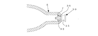
【解決手段】ピストン30は、ガス噴出流路を備え、封板7を開孔するピン部と、ピストン案内穴25の内壁に密着されるOリング38を装着するOリング装着部とを備え、ガス発生器40の作動前は、ピストンは、ピン部がシート29の前面に位置し、Oリング装着部がガス抜き穴26よりガス発生器側に位置し、ガス発生器の作動後は、ガス発生剤の燃焼によっるガス圧によって、ピストンは、ガスボンベ5側へ押し出され、ピン部がシート及び封板を刺してガスボンベ内に侵入し、ガス噴出流路を介してガスをガス放出穴24から噴出して膨張ユニットを展開し、Oリング装着部がガス抜き穴よりガスボンベ側へ移動し残圧をガス抜き穴から放出する。
【選択図】図2Disclosed is a gas cylinder opening device that uses an agent having a non-explosive composition to quickly expand an expansion unit such as a life jacket in a stable time without being restricted by the Explosives Control Law.
A piston 30 includes a gas ejection flow path, and includes a pin portion that opens a sealing plate 7 and an O-ring mounting portion that mounts an O-ring 38 that is in close contact with an inner wall of a piston guide hole 25. Before the operation of the gas generator 40, the piston has the pin portion positioned on the front surface of the seat 29, the O-ring mounting portion positioned on the gas generator side from the gas vent hole 26, and after the operation of the gas generator, the gas The piston is pushed out to the gas cylinder 5 side by the gas pressure generated by the combustion of the generating agent, the pin portion pierces the sheet and the sealing plate and enters the gas cylinder, and the gas is discharged into the gas discharge hole 24 through the gas ejection channel. The O-ring mounting part moves from the gas vent hole to the gas cylinder side and discharges the residual pressure from the gas vent hole.
[Selection] Figure 2
Description
本発明は、救命胴衣等の膨張ユニットを素早く安定した時間で展張させることが可能なガスボンベ開孔装置に関する。 The present invention relates to a gas cylinder opening device capable of quickly and stably expanding an expansion unit such as a life jacket.
ガスボンベ内のガスによって展張される膨張ユニットは、例えば、以下のものが知られている。
(1)海難事故、水難事故の際に着用者を水上に浮かせる救命胴衣
(2)海難事故、水難事故の際の船舶からの脱出や、水害発生時に被災者を救出する際に使用される救命ボート
(3)事故、災害発生時に負傷者を搬送する際に使用されるエアバック式担架
(4)ブイを海面に浮遊させるフロートを展張させるブイ用フロート
(5)火災等の災害発生時に、高所からの緊急脱出用として使用される救命マット
(6)バイク転倒時の搭乗者の保護、負傷軽減を担い、転倒時に膨張するバイク用救命胴衣
(7)高所作業から転倒した際の、転倒者の保護、負傷軽減を担い、転倒時に膨張する衝撃吸収用救命胴衣
For example, the following expansion units are known that are expanded by the gas in the gas cylinder.
(1) Life jacket that lifts the wearer to the surface in the event of a marine accident or drowning accident (2) Lifesaving used to escape from a ship in the event of a marine accident or drowning accident, or to rescue a victim in the event of a flood Boat (3) Airbag-type stretcher used for transporting injured people in the event of an accident or disaster (4) Float for a buoy that floats a float that floats the buoy on the sea surface (5) High in the event of a disaster such as a fire Life mats used for emergency escape from places (6) Bike life jackets that protect passengers and reduce injuries when a motorcycle falls, and inflate when falling (7) Fall when falling from work at high altitude Life jacket for shock absorption that protects and reduces injury and expands when falling
これらの膨張ユニットを展張させる装置は、膨張ユニットの内部にガスボンベを配置するので、保管時は小型でコンパクトなため取扱いが容易である。また、救命胴衣等は、着用時は着用者の動作に負担を与えない。ガスボンベは緊急時にのみ開封させ、内部のガスを噴出して膨張ユニットを展張させる。
ガスボンベの開封は、緊急性が高い時であり、特に、救命マットや転倒者を保護する救命胴衣では、被災者、被害者を守るためにも、素早く膨張ユニットを展張させる必要がある(数百msオーダーでの展張が要求される)。
そのため、ガスボンベ内のガスは、瞬時に噴出させる必要があり、その噴出時間も安定したものが必要とされる。
Since devices for expanding these expansion units have gas cylinders arranged inside the expansion units, they are easy to handle because they are small and compact during storage. Also, life jackets do not burden the wearer's movement when worn. The gas cylinder is opened only in an emergency, and the expansion unit is expanded by ejecting the gas inside.
Opening gas cylinders is a time of urgency, especially in life jackets that protect life mats and fallers, it is necessary to quickly expand the expansion unit to protect the victims and victims (hundreds of (Extension in the ms order is required).
Therefore, the gas in the gas cylinder needs to be ejected instantaneously, and a gas whose ejection time is stable is required.
従来、救命胴衣等の膨張ユニットを展張させるためにガスボンベの封板を開孔する装置は、例えば、火薬又は爆薬の圧力により、ガスボンベの封鎖板を直接破砕する装置(例えば、特許文献1参照)、花火起爆装置の衝撃波により爆発チャージが起動し、衝撃波によりガスボンベのケーシングに穴を開ける装置(例えば、特許文献2参照)、起爆装置の曝圧によってピストンのヘッドがガスボンベの封板を突き破る装置(例えば、特許文献3参照)、機械式によるガスボンベ開封装置(例えば、特許文献4参照)が知られている。 2. Description of the Related Art Conventionally, an apparatus for opening a gas cylinder sealing plate to expand an expansion unit such as a life jacket is an apparatus that directly crushes a gas cylinder sealing plate by the pressure of an explosive or explosive (see, for example, Patent Document 1). , An apparatus in which an explosion charge is activated by a shock wave of a pyrotechnic device and a hole is made in the casing of the gas cylinder by the shock wave (see, for example, Patent Document 2), and a device in which a piston head breaks through a gas cylinder sealing plate by the pressure of the detonator For example, a patent document 3) and a mechanical gas cylinder unsealing device (for example, see patent document 4) are known.
特許文献1は、起爆手段による爆薬の爆発の圧力により流体封入容器(ガスボンベ)の一端を直接開封させ、流体封入容器の流体を瞬時に噴出させる空気袋膨張装置を開示する。
特許文献1の空気袋膨張装置は、流体を流体封入容器から常に瞬時に噴出させることができるので、例えば、高所からの落下衝撃を吸収する人体用補助具等、空気袋の膨張速度及び確実性を要求される場合に極めて有利である。
特許文献1は、この空気袋膨張装置を人体用衝撃吸収補助具に適用した例を開示する。この人体用衝撃吸収補助具によれば、例えば、高所から転落した場合等に空気袋を瞬時に膨張させ、空気袋によって人体への落下衝撃を吸収することができるので、建設現場のような高所作業場等の作業者にとって極めて有利である。
Since the air bag inflating device of
特許文献2は、救命胴着や、いかだのような膨張式ユニット用の穿刺デバイスを含むガス管理装置、特に救命胴着のための装置と、加圧されたガスボンベから膨張式ユニットまでガスを移送する管理装置とを使用する方法と装置とを開示する。
特許文献2のガス管理装置は、気圧調節されたガスを含んでいる容器(ガスボンベ)のケーシングにしっかり固定できるガス入口と、ケーシングに穴をあけるために膨張式ユニットと穿刺デバイスにしっかり固定できるガス出口とを有し、穿刺デバイスは、起動された時、容器のケーシングに穴をあける衝撃波を生成する花火起爆装置を含み、容器からのガスを膨張式ユニットに向けて放出させ、花火起爆装置が一つの刺激印加体及び爆発チャージャを含み、刺激印加体のエネルギーが、衝撃波を作製するために爆発チャージャを起動させる。
The gas management apparatus disclosed in
特許文献3は、折り畳み自在のエアバッグと、このエアバッグを膨らませるためのガスボンベと、このガスボンベの封板を開封する手段とを有し、ガスボンベの封板を開封する手段を、衝撃センサーによる電気的信号により作動する起爆装置の起爆エネルギーによりピストンを作動させガスボンベの封板を突き破る。
特許文献3は、ピストンを、ボンベの開封が容易となり、しかも開孔部径が大きくなるように、先端をテーパー状に肉薄に形成する。
特許文献3は、ピストンの復帰がスムースになるように、ピストンにオリフィスを設け、起爆装置作動後の爆圧をオリフィスを通じて噴出孔から放出させる。
特許文献3は、ピストンの復帰がよりスムースになるように、ピストンとガスボンベとの間にスプリングを介在させる。
In
In
In
特許文献4は、火薬を使用しないボンベ開封装置を開示する。
特許文献4は、ボンベ開封装置を搭載するシャーシ内にボンベを収納し、このシャーシの内壁には突き当て面を形成して圧縮コイルスプリングの一端側に突き当て、その他端側はシャーシ内に遊嵌させた支持具の押圧面により押圧し、支持具は、ボンベを支持固定させ、シャーシは、封止板の上方に位置させて中空針を取り付け、シャーシの周面上部は、挿通穴を形成し、シャーシの上部はヒンジを形成してこのヒンジを中心にして矢印方向に回動可能にレバーを取り付け、このレバーのシャーシ側は、テーパ部が形成され、このテーパ部が挿通穴に挿通できるようにし、レバーは、引っ掛け部に保持材を引っ掛け、この保持材をシャーシの外周に巻きつけ、シャーシの表面は、発熱体を保持材と接触するように配置する。
In
特許文献1〜3は、火薬を用いているため、火薬類取締法の規制を受ける。
特許文献1〜3は、火薬類取締法の適用を受けない場合でも、装置は非特許文献1,2,3,4に示す適用除外品告示内容に沿った仕様へ制限される。
特許文献1,2は、火薬によりボンベ封板を破るため、薬剤の燃焼時の圧力で直接封板を破砕させる機構となり、ピストンに圧力を与え衝撃力を増加し封板を開孔させる方法より、多くの薬量が必要となる。
火薬の量が多くなると、発生する圧力が高くなるため、作動時に装置筐体の破壊及び筐体破片の飛散が生じる危険性が増加する。
そのため、薬量増加に伴い、装置の大型化及び高強度化が必要になる。
Since patent documents 1-3 use explosives, they are regulated by the Explosives Control Law.
In
Since
When the amount of explosives increases, the generated pressure increases, so that the risk of destruction of the device casing and scattering of casing fragments increases during operation.
For this reason, it is necessary to increase the size and strength of the apparatus as the dosage increases.
特許文献3は、起爆装置によりピストンを加圧し、ピストンによりガスボンベ封板を破る方法が記載され、ピストン先端をテーパー状に肉薄に形成することで、封板の開孔が容易となり、開孔部径が大きくなると記載されているが、ピストン先端をテーパー状に肉薄に形成すると、加圧されたピストンがボンベ封板穴に対して傾いて移動した場合(以下、芯ずれと称する。)、ピストンが侵入しないため、ピストンにより封板を適切に開孔できない。
なお、ボンベ封板穴以外の箇所はピストンの侵入が不可能である。
It should be noted that the piston cannot enter the portion other than the cylinder sealing plate hole.
特許文献3は、「移動後のピストンの復帰をスムースにするため、ピストンにオリフィスを設け、起爆装置作動後の爆圧をオリフィス介して噴出孔から放出する、または、シリンダ室の内径に対してピストンの外径を小さめに設定する」と記載するが、ピストンの外径を小さくし、シリンダ室とのクリアランスを大きくした場合は、特にピストン移動時の芯ずれが発生し易くなる。
ピストンにオリフィスを設けたり、シリンダ室とピストンのクリアランスを大きくした場合は、起爆装置作動時の圧力がオリフィス部やクリアランス部より漏れるため、ピストンを効率よく加圧できない。
よって、圧漏れ分を考慮した発生ガス量設定が必要であり、その結果、より多くの薬量が必要となる。
そのため、薬量増加に伴い、装置の大型化及び高強度化が必要になる。
If the piston is provided with an orifice or the clearance between the cylinder chamber and the piston is increased, the pressure during operation of the detonator leaks from the orifice and the clearance, so that the piston cannot be pressurized efficiently.
Therefore, it is necessary to set the amount of generated gas in consideration of the pressure leakage, and as a result, a larger amount of drug is required.
For this reason, it is necessary to increase the size and strength of the apparatus as the dosage increases.
特許文献3は、起爆装置作動後の爆圧を放出することでピストンが復帰しやすくなることを狙ってはいるが、ピストンの復帰状況は、薬剤燃焼後の固形残渣発生状況でも変化する。
たとえ起爆装置の爆圧を放出しても、ピストン周囲に固形残渣が付着すると、ピストンに付着した固形残渣とシリンダ室とが噛み込み、ピストンは元の位置に戻らなくなる。
この場合、ピストンとガスボンベとの間にスプリングを介在させても、ピストンは固定されているため、移動したピストンの復帰は困難になる。
ピストンが復帰しないと、封板開孔部をピストンが塞いでしまうため、ガスボンベ内のガス噴出時間が長くなる或いはガスが噴出しないといった事象が生じ、ガス噴出時間が安定しなくなる。
Even if the explosion pressure of the detonator is released, if a solid residue adheres to the periphery of the piston, the solid residue attached to the piston and the cylinder chamber bite, and the piston does not return to its original position.
In this case, even if a spring is interposed between the piston and the gas cylinder, since the piston is fixed, it is difficult to return the moved piston.
If the piston does not return, the piston closes the sealing plate opening, so that an event occurs in which the gas ejection time in the gas cylinder becomes longer or the gas does not eject, and the gas ejection time becomes unstable.
特許文献4は、機械式のボンベ開封方法であるが、中空針にスリットを設けた針を使用する実施形態が記載されている。
この形状のピストンを薬剤燃焼時のガスにより加圧しガスボンベ封板を開孔させると、中空部より圧漏れが生じる。
そのため、圧漏れ分を考慮した発生ガス量設定が必要であり、より多くの薬量が必要となる。
その結果、薬量増加に伴い、装置の大型化及び高強度化が必要になる。
また、加圧されたピストンがガスボンベ封板穴に対して芯ずれすると、ピストンが侵入しないため、ピストンにより封板を適切に開孔できない。
When a piston of this shape is pressurized with gas during chemical combustion to open the gas cylinder sealing plate, pressure leakage occurs from the hollow portion.
Therefore, it is necessary to set the amount of generated gas in consideration of the pressure leakage, and a larger amount of drug is required.
As a result, it is necessary to increase the size and strength of the device as the dosage increases.
Further, when the pressurized piston is misaligned with respect to the gas cylinder sealing plate hole, the piston does not enter, so that the sealing plate cannot be appropriately opened by the piston.
本発明は斯かる従来の問題点を解決するために為されたもので、その目的は、非火薬組成からなる薬剤を使用することで、火薬類取締法の規制を受けず、救命胴衣等の膨張ユニットを素早く安定した時間で展張させることが可能なガスボンベ開孔装置を提供することにある。 The present invention has been made to solve such conventional problems, and its purpose is to use a drug having a non-explosive composition so that it is not subject to the regulations of the Explosives Control Law, such as a life jacket. It is an object of the present invention to provide a gas cylinder opening device capable of expanding an expansion unit quickly and in a stable time.
請求項1に係る発明は、
開口部を封鎖部で密封する展開可能な膨張ユニット内に配置されたガスボンベの口部に設けた封板を開孔し、前記ガスボンベ内のガスを噴出して前記膨張ユニットを展開するガスボンベ開孔装置において、前記封鎖部に装着され、前記ガスボンベの口部を装着し、前記ガスボンベの封板を開孔し、前記ガスボンベ内のガスを前記膨張ユニット内に噴出させる開孔器と、前記開孔器に装着された前記ガスボンベの封板の前面に配されるシートと、前記ガスボンベの口部と対向して前記開孔器に装着され、非火薬組成部物から成るガス発生剤の燃焼によってガス圧を発生するガス発生器と、前記開孔器内で前記シートと前記ガス発生器との間に配され、前記ガス発生器のガス圧によって前記封板を開孔するピストンとを備え、前記開孔器は、前記封鎖部に装着される装着部と、前記ガスボンベの口部を装着するガスボンベ取付部と、前記ピストンを配するピストン案内穴と、前記ガス発生器を装着するガス発生器取付部と、前記ピストン案内穴と連通するガス放出穴と、前記ピストン案内穴と連通し、前記ガス放出穴と離間して設けられるガス抜き穴とを備え、前記ピストンは、ガス噴出流路を備え、前記封板を開孔するピン部と、前記ピストン案内穴の内壁に密着されるOリングを装着するOリング装着部とを備え、前記ガス発生器の作動前は、前記ピストンは、前記ピン部が前記シートの前面に位置し、前記Oリング装着部が前記ガス抜き穴より前記ガス発生器側に位置し、前記ガス発生器の作動後は、前記ピストンは、前記ガス発生剤の燃焼によるガス圧によって前記ガスボンベの口部側へ押し出され、前記Oリング装着部が前記ガス抜き穴より前記ガスボンベの口部側へ移動し残圧を前記ガス抜き穴から放出し、前記ピン部が前記シート及び前記封板を刺して前記ガスボンベの口部内に侵入し、前記ガス噴出流路を介して前記ガスを前記ガス放出穴から噴出して前記膨張ユニットを展開することを特徴とする。
The invention according to
A gas cylinder opening for opening a sealing plate provided at the mouth of a gas cylinder arranged in a deployable expansion unit that seals the opening with a sealing part, and for discharging the gas in the gas cylinder to expand the expansion unit In the apparatus, an opening device that is attached to the sealing portion, attaches a mouth portion of the gas cylinder, opens a sealing plate of the gas cylinder, and ejects gas in the gas cylinder into the expansion unit, and the opening A gas is produced by combustion of a gas generating agent composed of a non-explosive composition component, which is mounted on the opener facing the mouth of the gas cylinder and a sheet disposed on the front surface of the sealing plate of the gas cylinder mounted on the container. A gas generator that generates pressure, and a piston that is disposed between the sheet and the gas generator in the aperture, and that opens the sealing plate by the gas pressure of the gas generator, The aperture A mounting part to be attached to the chain part, a gas cylinder attaching part for attaching the mouth part of the gas cylinder, a piston guide hole for arranging the piston, a gas generator attaching part for attaching the gas generator, and the piston guide; A gas discharge hole that communicates with the hole; and a gas vent hole that communicates with the piston guide hole and is spaced apart from the gas discharge hole. The piston includes a gas ejection channel and opens the sealing plate. A pin portion that is perforated, and an O-ring mounting portion that mounts an O-ring that is in close contact with the inner wall of the piston guide hole, and before the operation of the gas generator, the piston has the pin portion on the front surface of the seat. The O-ring mounting portion is positioned on the gas generator side of the gas vent hole, and after the operation of the gas generator, the piston is moved to the gas cylinder by the gas pressure generated by the combustion of the gas generating agent. Extruded to the mouth side, the O-ring mounting part moves to the mouth part side of the gas cylinder from the gas vent hole to release residual pressure from the gas vent hole, and the pin part pierces the sheet and the sealing plate Then, the gas is introduced into the mouth of the gas cylinder, and the expansion unit is expanded by ejecting the gas from the gas ejection hole through the gas ejection channel.
請求項2に係る発明は、請求項1に係る発明記載のガスボンベ開孔装置において、前記ピストンは、前記ガス噴出流路を備え、前記ガスボンベの封板を開孔し前記ガスボンベの口部内に侵入するピン部と、前記Oリングを取り付け、前記ガスボンベの封板に接触した時点で前記ピン部の侵入を終了させるOリング装着部とを備えることを特徴とする。
請求項3に係る発明は、請求項2に係る発明記載のガスボンベ開孔装置において、前記ガス噴出流路は、前記ピン部の長手方向に溝を設けることによって構成されることを特徴とする。
According to a second aspect of the present invention, in the gas cylinder opening device according to the first aspect of the present invention, the piston includes the gas ejection channel, opens a sealing plate of the gas cylinder, and enters the opening of the gas cylinder. And an O-ring mounting portion that attaches the O-ring and terminates the intrusion of the pin portion when it comes into contact with the sealing plate of the gas cylinder.
According to a third aspect of the present invention, in the gas cylinder opening device according to the second aspect of the present invention, the gas ejection flow path is configured by providing a groove in the longitudinal direction of the pin portion.
請求項4に係る発明は、請求項2に係る発明記載のガスボンベ開孔装置において、前記ガス噴出流路は、前記ピン部の長手方向に溝を設け、前記Oリング装着部の壁部に前記溝に連なる切欠部を設けることによって構成されることを特徴とする。
請求項5に係る発明は、請求項2に係る発明記載のガスボンベ開孔装置において、前記ガス噴出流路は、前記ピン部にネジ切り加工を施して螺旋部を形成することによって構成されることを特徴とする。
According to a fourth aspect of the present invention, in the gas cylinder opening device according to the second aspect of the present invention, the gas ejection flow path is provided with a groove in the longitudinal direction of the pin portion, and the wall portion of the O-ring mounting portion is provided with the groove. It is characterized by being provided with a notch continuous to the groove.
According to a fifth aspect of the present invention, in the gas cylinder opening device according to the second aspect of the present invention, the gas ejection flow path is configured by forming a spiral portion by threading the pin portion. It is characterized by.
請求項6に係る発明は、請求項2に係る発明記載のガスボンベ開孔装置において、前記ガス噴出流路は、前記ピン部にネジ切り加工を施して螺旋部を形成し、前記Oリング装着部の前記ピン部側壁部に前記溝に連なる切欠部を設けることによって構成されることを特徴とする。
請求項7に係る発明は、請求項2に係る発明記載のガスボンベ開孔装置において、前記ガス噴出流路は、前記ピン部に軸長方向に中空部を設けると共に、前記中空部と垂直方向に前記中空部と連通する貫通穴を設けることによって構成されることを特徴とする。
According to a sixth aspect of the present invention, in the gas cylinder opening device according to the second aspect of the present invention, the gas ejection passage forms a spiral portion by threading the pin portion, and the O-ring mounting portion It is characterized by comprising the notch part connected to the said groove | channel in the said pin part side wall part.
According to a seventh aspect of the present invention, in the gas cylinder opening device according to the second aspect of the present invention, the gas ejection flow path is provided with a hollow portion in the axial direction of the pin portion and in a direction perpendicular to the hollow portion. It is configured by providing a through hole communicating with the hollow portion.
請求項8に係る発明は、請求項2に係る発明記載のガスボンベ開孔装置において、前記ガス噴出流路は、前記ピン部に軸長方向に中空部を設け、前記Oリング装着部の前記ピン部側壁部に前記中空部と垂直方向に前記中空部と連通する貫通穴を設けることによって構成されることを特徴とする。
請求項9に係る発明は、請求項1に係る発明記載のガスボンベ開孔装置において、前記ピストンは、前記ガス噴出流路を備え、前記ガスボンベの封板を開孔し前記ガスボンベ内に侵入するピン部と、前記ガスボンベの封板に接触した時点で前記ピン部の侵入を終了させるヘッド部と、前記Oリングを取り付けるOリング装着部とを備えることを特徴とする。
According to an eighth aspect of the present invention, in the gas cylinder opening device according to the second aspect of the present invention, the gas ejection flow path is provided with a hollow portion in the axial direction of the pin portion, and the pin of the O-ring mounting portion. It is constituted by providing a through hole communicating with the hollow part in a direction perpendicular to the hollow part in the side wall part.
According to a ninth aspect of the present invention, in the gas cylinder opening device according to the first aspect of the present invention, the piston includes the gas ejection flow path, and the pin that opens the sealing plate of the gas cylinder and enters the gas cylinder. And a head part that terminates the intrusion of the pin part when it comes into contact with the sealing plate of the gas cylinder, and an O-ring mounting part that attaches the O-ring.
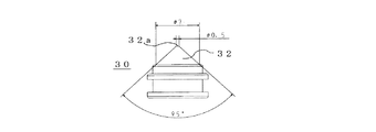
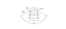
請求項10に係る発明は、請求項9に係る発明記載のガスボンベ開孔装置において、前記ピン部は、先端を平坦又は球状にし、前記先端側から19°〜130°の角度を付ける斜面を備えることを特徴とする。
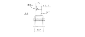
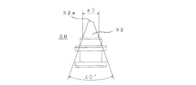
請求項11に係る発明は、請求項9に係る発明記載のガスボンベ開孔装置において、前記ピン部は、先端を平坦又は球状にし、前記先端側から終端部にかけて、10°〜95°の角度を付ける斜面を備えることを特徴とする。
According to a tenth aspect of the present invention, in the gas cylinder opening device according to the ninth aspect of the present invention, the pin portion includes a slope having a flat or spherical tip and an angle of 19 ° to 130 ° from the tip side. It is characterized by that.
According to an eleventh aspect of the present invention, in the gas cylinder opening device according to the ninth aspect of the invention, the pin portion has a flat or spherical tip, and has an angle of 10 ° to 95 ° from the tip side to the terminal portion. It is provided with a slope to be attached.
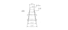
請求項12に係る発明は、請求項9に係る発明記載のガスボンベ開孔装置において、前記ピン部は、先端を平坦又は球状にし、前記先端側から19°〜130°の角度を付ける斜面を備え、前記ピン部中間から終端部にかけて、前記先端側に設けた角度より小さい角度を付ける斜面を備えることを特徴とする。
請求項13に係る発明は、請求項9に係る発明記載のガスボンベ開孔装置において、前記ガス噴出流路は、前記ピン部及び前記ヘッド部に溝を設け、前記ピン部及び前記ヘッド部の溝を連通させることによって構成されることを特徴とする。
According to a twelfth aspect of the present invention, in the gas cylinder opening device according to the ninth aspect of the present invention, the pin portion includes a slope having a flat or spherical tip and an angle of 19 ° to 130 ° from the tip side. Further, it is characterized in that a slope is provided to make an angle smaller than the angle provided on the tip side from the middle of the pin part to the terminal part.
According to a thirteenth aspect of the present invention, in the gas cylinder opening device according to the ninth aspect of the present invention, the gas ejection flow path is provided with a groove in the pin portion and the head portion, and the groove of the pin portion and the head portion. It is comprised by making it communicate.
請求項14に係る発明は、請求項9に係る発明記載のガスボンベ開孔装置において、前記ガス噴出流路は、前記ピン部にネジ切り加工を施して螺旋部を形成し、前記ヘッド部に溝を設け、前記螺旋部と前記溝とを連通させることによって構成されることを特徴とする。
請求項15に係る発明は、請求項9に係る発明記載のガスボンベ開孔装置において、前記ガス噴出流路は、前記ピン部に中空部を設け、前記ヘッド部は前記ピン部の中空部と垂直方向に貫通穴を設け、前記ピン部の中空部と前記ヘッド部の貫通穴とを連通させることによって構成されることを特徴とする。
According to a fourteenth aspect of the present invention, in the gas cylinder opening device according to the ninth aspect of the invention, the gas ejection flow path is formed by subjecting the pin portion to threading to form a spiral portion, and a groove in the head portion. Provided, and the spiral portion and the groove are communicated with each other.
According to a fifteenth aspect of the present invention, in the gas cylinder opening device according to the ninth aspect of the present invention, the gas ejection flow path is provided with a hollow portion in the pin portion, and the head portion is perpendicular to the hollow portion of the pin portion. A through hole is provided in a direction, and the hollow portion of the pin portion and the through hole of the head portion are communicated with each other.
本発明は、非火薬組成から成るガス発生剤を使用するため、火薬類取締法の規制を受けず、適用除外品告示に制限されない、ガスボンベ開孔装置を提供できる。
本発明は、ガス圧によりピストンを加圧してピストンを移動する時の圧漏れを防止するため、小型なガスボンベ開孔装置を提供できる。
本発明は、ピストンの復帰が生じなくとも、ガスボンベ内のガスが放出されるよう、ピン部にガス噴出流路を形成しておくため、ガスボンベ内のガスを、素早く安定した時間で噴出可能となるよう調整できる。
本発明は、ピストンのピン部の角度設定により封板を大きく開孔させ、また、ピストンの復帰が生じなくとも、ガスボンベ内のガスが放出されるよう、ピン部からヘッド部にかけて、ガス噴出流路を形成しておくため、ガスボンベ内のガスを、素早く安定した時間で噴出可能となるよう調整できる。
Since the present invention uses a gas generating agent having a non-explosive composition, it is possible to provide a gas cylinder opening device that is not restricted by the Explosives Control Law and is not limited to notification of exempted products.
The present invention can provide a small gas cylinder opening device in order to prevent pressure leakage when the piston is moved by pressurizing the piston with gas pressure.
In the present invention, since the gas ejection flow path is formed in the pin portion so that the gas in the gas cylinder is released even if the piston does not return, the gas in the gas cylinder can be ejected quickly and in a stable time. Can be adjusted.
According to the present invention, the sealing plate is largely opened by setting the angle of the pin portion of the piston, and the gas jet flow from the pin portion to the head portion so that the gas in the gas cylinder is released even if the piston does not return. Since the passage is formed, the gas in the gas cylinder can be adjusted so that it can be ejected quickly and in a stable time.
以下、本発明を図面に示す実施形態に基づいて説明する。
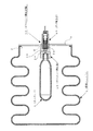
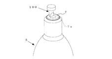
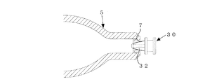
図1は本発明の一実施形態に係るガスボンベ開孔装置10を膨張ユニット1に取り付けた例を示す。
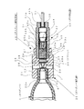
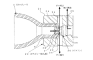
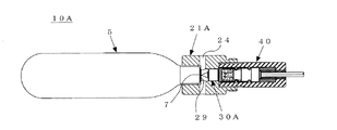
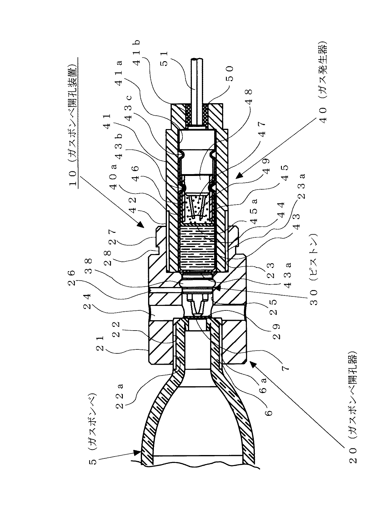
本実施形態において、ガスボンベ開孔装置10は、図1、図2に示すように、ガスボンベ開孔器20と、ガス発生器40とを備える。
膨張ユニット1は、開口部2にプレート3をボルト等により固定することによって封鎖される。膨張ユニット1は、ガスボンベ5から噴出するガスによって展開される。
なお、図1では、膨張ユニット1の構造形状が理解できるように、膨張ユニット1が一部展開した状態で示してあるが、作動前は、折り畳まれて目的とする用途に応じて容器等に収納される。
Hereinafter, the present invention will be described based on embodiments shown in the drawings.
FIG. 1 shows an example in which a gas
In this embodiment, the gas
The
In FIG. 1, the
プレート3の中央部は、内周に雌ネジ部(図示せず)を設けたガス発生器取付穴3aを設ける。ガス発生器取付穴3aには、ガスボンベ開孔器20のホルダ21の外周に設けた雄ネジ部27が螺着される。ホルダ21とプレート3との間には、プレート位置調整として、ワッシャ4がガスボンベ開孔器20のホルダ21の雄ネジ部27の一部とこの雄ネジ部27に連接して外周に設けた凹部28とに跨って装着される。
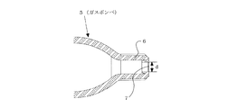
ガスボンベ5は、図2に示すように、内部に圧縮ガス又は液化ガスが充填され、口部6には封板7が装着され、封板7が開封されるとガスを噴出する。ガスボンベ5の口部6の外周には、雄ネジ部6aが設けられ、ガスボンベ開孔器20のホルダ21のガスボンベ取付穴22内に設けた雌ネジ部22aに螺着される。
The central portion of the
As shown in FIG. 2, the
ガスボンベ開孔器20は、図1、図2に示すように、ホルダ21と、シート29と、ピストン30と、ピストン30に取り付けられるOリング38とを備え、ガスボンベ5と共に膨張ユニット1の内部に配置される。
ホルダ21は、例えば、鉄、ステンレス、アルミニウム等の金属から成る筒状体で構成される。ホルダ21は、一端部にガスボンベ5の口部6に設けた雄ネジ部6aを螺着する雌ネジ部22aを設けたガスボンベ取付穴22を備え、他端部にガス発生器40の外周に設けた雄ネジ部42を螺着する雌ネジ部23aを設けたガス発生器取付穴23を備える。ガスボンベ取付穴22とガス発生器取付穴23とは同軸上に連通するように形成される。
ホルダ21は、他端部の外周にプレート3のガス発生器取付穴3aに設けた雌ネジ部(図示せず)を螺着させる雄ネジ部27を備え、この雄ネジ部27に連接してプレート位置調整のために装着されるワッシャ4を取り付けるための凹部28を備える。
As shown in FIGS. 1 and 2, the
The
The
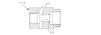
ガスボンベ取付穴22とガス発生器取付穴23との間には、ガスボンベ5の開孔後、ガスボンベ5内のガスを放出するガス放出穴24と、ピストン30及びシート29を配置するピストン案内穴25と、ピストン30の移動後の残圧を開放するガス抜き穴26とを備える。
ガス放出穴24及びガス抜き穴26は、ホルダ21の軸に対し、上下左右1箇所もしくは上下左右対称に設けられる。ガス放出穴24は、移動後のピストン30のヘッド部33に設けた溝34と連通する位置に設けられ、径は3.0mm以上が望ましい。
Between the gas
The
ガス抜き穴26は、ピストン30移動後のピストン30のOリング装着部35直後のピストン案内穴25と連通するように設けられ、ピストン30移動時はOリング38によって封鎖されてガス漏れを生じず効率よくピストン30を加圧でき、ピストン30がガスボンベ5の封板7を開孔した後に、残圧を開放することができる。ガス抜き穴26の径は0.5mm以上が望ましい。
シート29は、例えば、ポリエステル等の樹脂で構成され、図1、図2に示すように、ガスボンベ5の封板7の保護として、ピストン案内穴25内においてピストン30のピン部32の先端32a側に配置され、振動によりピストン30が動き封板7が損傷することを防ぐ。シート29の厚さは、小型なガスボンベ5の封板7の厚さと同程度の0.3mmが望ましい。
The
The
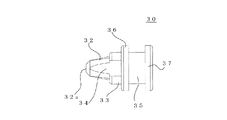
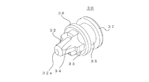
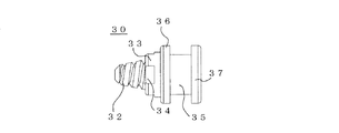
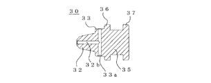
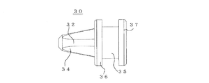
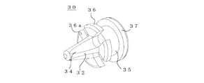
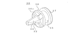
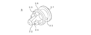
ピストン30は、例えば、鉄、ステンレス、アルミニウム等の金属で構成され、図1乃至図5に示すように、圧力を受けガスボンベ5の封板7に刺さり封板7を開孔するピン部32と、このピン部32に連接するヘッド部33と、このヘッド部33に連接するOリング装着部35とを備える。
ピン部32は、先端32aが平坦又は球状を為し、先端32aから後方に向かって広角になるように角度19°〜130°を付けることでピストン移動時の芯ずれが修正され、且つ、ガスボンベ5の封板7を大きく開孔することができる。
ヘッド部33は、ガスボンベ5の口部6の口径より大きくなるように、ピン部32の先端32aより外径が大きくなるテーパ形状に形成される。そのため、ピン部32がガスボンベ5の封板7に刺さり封板7を開孔した時点で、ピン部32の侵入を停止させることができる。
The
The
The
ピン部32とヘッド部33との間の外周には、ピストン30移動後にピストン30が復帰しなくとも、ガスボンベ5内のガス噴出流路を形成するための溝34を軸方向に形成する。
ヘッド部33の後部に、ヘッド部33に連接する壁部36とピストン30の後端部に位置する壁部37とでOリング38を装着するOリング装着部35を形成する。
Oリング38は、ガスボンベ開孔装置10の作動前のピストン案内穴25におけるピストン30の保持機能と、ガスボンベ開孔装置10の作動によるピストン30移動時のピストン案内穴25における圧漏れ及び芯ずれの防止機構とを有する。
On the outer periphery between the
An O-
The O-
ガス発生器40は、図1、図2に示すように、ガス発生部40aと、例えば、鉄、ステンレス、アルミニウム等の金属製のコップ形状を為す筒状体で構成され、ガス発生部40aを収納するホルダ41と、ガス発生部40aをホルダ41に固定するエポキシ系接着剤等のシール剤50とで構成される。
ガス発生器40は、ガスボンベ開孔器20のホルダ21のガス発生器取付穴23に設けた雌ネジ部23aに、ホルダ41の外周に設けた雄ネジ部42を螺着する。
ガス発生部40aは、片方のみ開放された筒状容器から成る有底の管体43と、ガス発生剤44と、キャップ45と、点火薬ホルダ46と、点火薬47と、電橋線付塞栓48とで構成される。
As shown in FIGS. 1 and 2, the
In the
The gas generating unit 40a includes a bottomed
管体43は、例えば、アルミニウム等の軟質金属材料で構成され、非火薬組成物であるガス発生剤44の反応熱及び反応ガス圧力で容易に破壊する。管体43の有底部頂点43aの肉厚は、0.1mmである。
管体43は、加工性の良い軟質金属材料であれば何でも良いが、例えば、銅を用いる電気雷管との混同を避けるため、アルミニウム(例えば、A1−6016−0等)を用いる。
管体43には、ガス発生剤44が0.05g〜0.30gの範囲で充填される。ガス発生剤44は、低振動・低騒音破砕薬剤ガンサイザー(日本工機株式会社製商品名)を使用する。これは、火薬類を用いた破砕方法と全く同じ手順で消費許可を必要とせずに岩盤等を破砕する非火薬破砕組成物(例えば、特開平11−029389号公報参照)である。
The
The
The
ガス発生剤44は、岩盤等を破砕する目的ではなく、このガス圧力をピストンを移動させる目的に変えるもので、その結果、ガス発生剤44の粒径を揃えることでガス圧力のバラツキを小さくできることを見出した。また、移動させるピストン形状に合わせてガス発生剤44の薬量を変えることは可能である。
ガス発生剤44は、例えば、表1に示すように、非火薬組成の薬剤で構成される。表1に示す非火薬組成の薬剤は、24タイラーメッシュ通過42タイラーメッシュ止まりの粒径に調整され、圧力バラツキを低減させている。燃焼時にはガス(圧力)を発生する。
The gas generating agent 44 is not intended to crush the bedrock or the like, but to change the gas pressure to the purpose of moving the piston. As a result, the gas pressure variation can be reduced by making the particle size of the gas generating agent 44 uniform. I found. Further, it is possible to change the dose of the gas generating agent 44 according to the piston shape to be moved.
For example, as shown in Table 1, the gas generating agent 44 is composed of a chemical having a non-explosive composition. The chemicals of the non-explosive composition shown in Table 1 are adjusted to a particle size of 24 Tyler mesh passage 42 Tyler mesh stopping, and reduce pressure variation. Gas (pressure) is generated during combustion.
管体43内には、充填されたガス発生剤44と点火薬47との混合防止のために隔壁と成る片方のみ開放された樹脂製の筒状容器から成る有底のキャップ45が配置される。
キャップ45は、点火薬47の反応熱及び反応ガス圧力で容易に破壊されやすいよう底部45aの肉厚を0.5mm以下とし、静電気による点火薬47への放電経路を遮断するため、ポリプロピレン(PP)、ポリエチレン(PE)等の樹脂を使用し、点火薬ホルダ46に挿入される。キャップ45及び点火薬ホルダ46には、非火薬組成物で構成する点火薬47と電橋線付塞栓48の電橋線(例えば、白金−イリジュウム線)49とが配置される。
点火薬47は、表2に示すように、非火薬組成の薬剤で構成される。点火薬47は、電橋線部49の熱により点火し、ガス発生剤44を燃焼させる。点火薬47は、0.06g〜0.20gの範囲内で填薬されると、正常に作動する。
In the
The cap 45 has a bottom 45a having a thickness of 0.5 mm or less so that it can be easily broken by the reaction heat and reaction gas pressure of the igniting agent 47, and in order to block the discharge path to the igniting agent 47 due to static electricity, ), A resin such as polyethylene (PE) is used and inserted into the
As shown in Table 2, the ignition powder 47 is composed of a chemical having a non-explosive composition. The igniting agent 47 is ignited by the heat of the bridge portion 49 and burns the gas generating agent 44. When the igniting agent 47 is filled in the range of 0.06 g to 0.20 g, it operates normally.
電橋線付塞栓48は、点火薬ホルダ46を挿入後、点火薬47が0.06g〜0.20gの範囲で填薬され、点火薬ホルダ46にキャップ45を挿入してから、ガス発生剤44が填薬された管体43内に圧入され、管体43の外側から2箇所にカシメ部43b,43cを形成することによって、管体43に固着される。なお、このカシメ部43b,43cは通常は2段であるが1段や3段の場合もある。
管体43を電橋線付塞栓48をカシメ後、ホルダ41に挿入し、シール剤50を、ホルダ41と電橋線付塞栓48と電橋線付塞栓48に連絡するリード線51との間に充填することで、ガス発生部40aとホルダ41とが固定される。
また、ガス発生部40aが発火した際の後方へのガス噴出は、ホルダ41に充填したシール剤50によって阻止される。
The
The
Further, the backward gas ejection when the gas generating part 40 a ignites is prevented by the sealing
次に、本実施形態の作用を説明する。
作動前のガスボンベ開孔装置10は、図1、図2に示すように、ホルダ21の一端部にガスボンベ5の口部6を取り付け、他端部にガス発生器40を取り付け、ホルダ21内のピストン案内穴25のシート29及びピストン30を配置した状態で、ガスボンベ5の封鎖部を構成するプレート3に装着される。
そして、ガスボンベ5とガスボンベ開孔器20を内包する膨張ユニット1は、折り畳まれて目的とする用途に応じて容器等に収納される。
また、ピストン30は、ピン部32がシート29の前面に位置し、Oリング装着部35に装着されたOリング38がガス抜き穴26よりガス発生器40側に位置し、Oリング装着部35の後方の壁部37がガス発生器40の管体43の前面に位置するように配される。
Next, the operation of this embodiment will be described.
As shown in FIGS. 1 and 2, the gas
And the expansion | swelling
The
作動時には、先ず、図示しない点火回路を介し、電橋線付塞栓48のリード線51より、電流が通電されると、電橋線49が高温になり、点火薬47が着火し、キャップ45の底部45aが破断する。
次に、点火薬47の燃焼により、ガス発生剤44が着火され、管体43の底部43aが破断する。
次に、ガス発生剤44の燃焼によりガスが発生し、ピストン30がホルダ21のピストン案内穴25内をシート29方向へ移動する。
At the time of operation, first, when a current is passed through the lead wire 51 of the
Next, the gas generating agent 44 is ignited by the combustion of the ignition powder 47, and the bottom 43 a of the
Next, gas is generated by combustion of the gas generating agent 44, and the
次に、ピストン30の移動に伴い、Oリング38がホルダ21のガス抜き穴26を通過すると、ホルダ21のガス抜き穴26よりガス発生剤44の残圧が開放される。
次に、移動したピストン30は、図5に示すように、シート29とガスボンベ5の封板7とを破断する。
次に、ガスボンベ5の圧縮ガス又は液化ガスが、破断した封板7とピン部32の隙間やピストン30のガス噴出流路を形成する溝34を介し、ホルダ21のガス放出穴24より噴出する。
次に、ガス放出24から放出されるガスによって膨張ユニット1を素早く安定して展開する。
Next, when the O-
Next, the moved
Next, the compressed gas or liquefied gas of the
Next, the
以上のように、本実施形態に係るガスボンベ関孔装置10は、非火薬組成による薬剤を使用しているため、火薬類取締法の規制を受けない。
また、本実施形態に係るガスボンベ関孔装置10は、適用除外品告示内容にも制限されず、自由な形状のガスボンベ開孔装置10が提供できる。
また、本実施形態に係るガスボンベ関孔装置10は、ピストン30を加圧し、ピストン30によりガスボンベ5の封板7を開孔するため、圧力により直接ガスボンベ5の封板7を破る従来方法より使用薬量は少量となり、装置の小型化に繋がる。
As described above, the gas
Moreover, the gas cylinder hole-opening
Moreover, the gas cylinder related-
また、本実施形態に係るガスボンベ関孔装置10は、ホルダ21のピストン案内穴25をピストン30が移動する際は、Oリング38によって気密状態を維持したままピストン30は移動し、圧漏れが発生せず、効率よくピストン30が加圧される。
そのため、使用薬量は少量となり、装置の小型化に繋がる。
また、本実施形態に係るガスボンベ関孔装置10は、残圧開放機構として、ピストン30移動後のOリング装着部35直後にガス抜き穴26を設けているので、ピストン30移動時はOリング38によって封鎖されてガス漏れを生じず効率よくピストン30を加圧でき、ピストン30がガスボンベ5の封板7を開孔した後に、残圧を開放することができる。
Further, in the gas cylinder related
Therefore, the amount of drug used is small, which leads to downsizing of the device.
Further, the gas cylinder related
次に、ピストン30の芯ずれについて説明する。
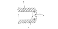
先ず、図6に基づいて、ガスボンベ5の封板7の穴径dについて説明する。
ガスボンベ5の封板7の穴径dは、ガスボンベの種類により異なる。ただし、そのガスボンベの種類毎に封板穴径は決まっているため、封板7を開孔させる際は、封板7の穴径d以上の開孔部径となることはない。
なお、ガスボンベ5の封板7の開孔部径が大きくなるほど、ガスボンベ5内のガスは多く噴出される。
よって、可能な限りガスボンベ5の封板7を大きく開孔させることで、ガスボンベ5内のガス噴出時間を短くさせることができる。
Next, misalignment of the
First, the hole diameter d of the sealing
The hole diameter d of the sealing
Note that the larger the diameter of the opening of the sealing
Therefore, the gas ejection time in the
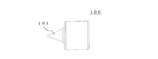
一方、先行技術(特許文献3)に記載の、火薬によりピストンを加圧し、ピストンによりガスボンベの封板を破る技術では、ピストン形状は「ピストン先端はテーパー状に肉薄に形成することで、封板の間孔が容易となり、開孔部径が大きくなる」ことが示されている。
なお、ピストンによりガスボンベ封板を開孔させた場合、封板はピン形状に沿って開孔する。
例えば、図7に示すように、ピン部101の先端を尖らせたピストン100にてガスボンベ封板を開孔させた場合は、図8に示すように、ピストン侵入後の封板7は、ピン部101の形状に沿って開孔することになる。
On the other hand, in the technology described in the prior art (Patent Document 3) in which the piston is pressurized with explosives and the sealing plate of the gas cylinder is broken with the piston, the piston shape is “the tip of the piston is formed into a tapered shape, It is shown that the hole becomes easier and the diameter of the opening becomes larger.
In addition, when the gas cylinder sealing plate is opened by the piston, the sealing plate opens along the pin shape.
For example, as shown in FIG. 7, when the gas cylinder sealing plate is opened by the
よって、ピン部101の先端を尖らせたピストン100にて開孔された封板7は、ピン部101の先端側の断面径が細いために、その開孔部径d’が小さくなる。
以上より、封板開孔部径を大きくしたい場合は、ピストン100のピン部101は、先端から終端までストレートの形状が、最も大きく封板7を開孔でき、ピン形状も、より簡単な加工で済むことが解る。
ただし、先行技術(特許文献3)に記載のように、ピン部101をストレート形状にした場合は、封板穴径とピン部の径の設定次第では、図9に示すように、ピストン100移動時にピストン100の芯ずれが生じると、ピン部101が封板7の穴7aに刺さらず、ピストン100が移動しない。なお、先行技術(特許文献3)では、これらの危険性は示されいない。
Therefore, since the sealing
From the above, when it is desired to increase the diameter of the opening portion of the sealing plate, the pin portion 101 of the
However, as described in the prior art (Patent Document 3), when the pin portion 101 has a straight shape, depending on the setting of the sealing plate hole diameter and the pin portion diameter, as shown in FIG. If the
仮に、ピストン100の先端をテーパ状に肉薄に形成したとしても、封板7の穴径に対し、ピン部先端の径とピン部終端の径とが同じであるため、当該ピストン形状では、芯ずれが生じると、ピストン100は移動しない可能性がある。
また、先行技術(特許文献3)では、「シリンダ室の内径に対してピストンの外径を小さめに設定する」とあるため、特にピストン移動時の芯ずれが発生し易くなる。なお、芯ずれの影響が少なくなるよう、ピン部の径を細くした場合は、ピン移動後の封板開孔部径が小さくなる。
よって、開孔部径が大きくなるといった内容と矛盾が生じる。
Even if the tip of the
Further, in the prior art (Patent Document 3), since “the outer diameter of the piston is set smaller than the inner diameter of the cylinder chamber”, misalignment particularly occurs when the piston moves. In addition, when the diameter of a pin part is made thin so that the influence of center shift | offset | difference may become small, the sealing plate opening part diameter after pin movement becomes small.
Therefore, a contradiction arises with the content that the diameter of the aperture is increased.
これに対し、本実施形態のガスボンベ開孔装置10のピストン30は、ガスボンベ5の封板7を開孔しガスボンベ5内に侵入するピン部32と、ガスボンベ5の封板7に接触した時点でピン部32の侵入を終了させるヘッド部33と、Oリング38を取り付けるOリング装着部35とを備え、ピストン30にOリング38を装着することで、作動前のピストン30の位置ずれを防止し、またピストン30移動時にピストン30の傾きを防止できる。
そのため、本実施形態のガスボンベ開孔装置10では、ピストン30の芯ずれが生じにくい。
On the other hand, when the
Therefore, in the gas
次に、ピン部32の形状について説明する。
先ず、ピン部32は、図10、図11に示すように、先端32aを平坦又は球状にし、ピン部32の先端側へ19°〜130°の角度を付ける。
第1に、ピン部32の先端32aを平坦にすることで、ピストン30全長が短くなる。よって、ガスボンベ開孔装置10全体の小型化に繋がる。
また、ピン部32の先端32aを平坦にすることで、ピン部32の先端32aを尖らせた場合より、振動によりピストン30が移動しても、ガスボンベ5の封板7を損傷させる可能性が低減できる。
なお、振動により封板7を損傷させない観点からは、ピン部32の先端32aは平坦のみに限らず、球状であっても良い。
Next, the shape of the
First, the
First, the entire length of the
Further, by flattening the
From the viewpoint of not damaging the
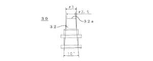
第2に、例えば、封板7の穴径最大3.5mmのガスボンベ5に対しては、ピン部32の終端径を3mmとし、最低でも19°の角度を付けることで、ピン部32の先端32aの径は、ピン部32の長さが短めの時点(例えば、図10では約3mm)で封板7の穴径より1mm小さい2.5mmとなる。
よって、ガスボンベ5の封板7の穴径に対しピン部32の先端32aの径は小さくなることより、ピストン30移動時に芯ずれが生じてもピン部32の先端32aはガスボンベ5の封板7に刺さる。
Secondly, for example, for the
Therefore, since the diameter of the
また、ピン部32の先端32aには傾斜を設けているため、ピストン30の侵入とともにピストン30の芯ずれが修正される。
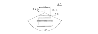
また、図11に示すように、ピン部32の終端径が7mmの場合は、最大で130°の角度を付ける。角度130°であれば、ピン部32の先端32aは平坦形状となり、振動によるガスボンベ5の封板7の損傷を低減できる。
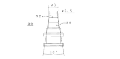
次に、ピン部32は、図12、図13に示すように、先端32aを平坦又は球状にし、ピン部32の先端32a側から終端部にかけて10°〜95°の角度を付ける。
ピン部32の先端32a側のみでなく、ピン部32の先端32a側から終端部にかけて、全体的に10°〜95°の範囲で角度を付けた場合でも、ピストン30移動時の芯ずれは修正できる。
Further, since the
Moreover, as shown in FIG. 11, when the terminal diameter of the
Next, as shown in FIGS. 12 and 13, the
Even when the angle is set within the range of 10 ° to 95 ° not only from the
例えば、封板7の穴径最大3.5mmのガスボンベ5に対しては、ピン部32の終端径を3mmとし、最低でも10°の角度を付けることで、ピン部32の先端32aの径は、ピン部32の長さが短めの時点(例えば、図12では約3mm)で封板穴径より1mm小さい2.5mmとなる。
また、ピン部32の終端径が7mmの場合は、図13に示すように、最大で95°の角度を付けることで、ピン部32の先端32aは平坦形状となる。
また、この場合は、ピン部32の先端32a側のみでなく、ピン部32の全体が傾斜を有するため、より芯ずれ修正機能が働く。
For example, for the
Further, when the terminal diameter of the
Further, in this case, not only the
ただし、ピン部32の全体に角度を付ける場合は、芯ずれ修正とピン部32の長さを短くすることを考慮して、ピン部32の全体に付ける角度を大きくしていくほど、ピストン30移動後の封板7の開孔部径は小さくなる。
例えば、ピン部32の長さは変化させない条件で、図14に示すように、ピン部32の終端径を3mmとし角度を10°にした場合と、図15に示すように、ピン部32の終端径を3mmとし角度を40°にした場合とでは、角度40°の方がピン部32の傾斜はきつくなり、より芯ずれが修正される。
ただし、ピン部32の断面径は小さくなるため、封板7の開孔部径も小さくなる。
However, when an angle is given to the
For example, under the condition that the length of the
However, since the cross-sectional diameter of the
次に、ピン部32は先端32aを平坦又は球状にし、ピン部32の先端32a側から19°〜130°の角度を付け、且つ、ピン部32の中間から終端部にかけて、ピン部32の先端32a側に設けた角度より小さい角度を付ける。
ピストン30の芯ずれ修正と封板7の開孔部増加をバランスよく狙いたい場合は、ピン部32の先端32a側から19°〜130°の角度を付け、且つ、ピン部32の中間から終端部にかけて、ピン部32の先端32a側に設けた角度より小さい角度を付したピストン30を用いることが有効となる。
例えば、封板7の穴径最大3.5mmのガスボンベ5に対しては、図16に示すように、ピン部32の終端径を3mmとし、先端側から最低でも19°の角度を付ける。
また、ピン部32の中間から終端部にかけては、ピン部32の先端32a側角度19°より小さい角度15°の傾斜を付ける。
Next, the
When it is desired to balance the misalignment correction of the
For example, for the
Further, an inclination of an angle of 15 °, which is smaller than the angle of 19 ° on the
また、例えば、図17に示すように、ピン部32の終端径を7mmとし、ピン部32の先端32a側から130°の角度を付け、ピン部32の中間から終端部にかけては、先端側角度130°より小さい角度10°の傾斜を設ける。
これらの場合は、ピン部32の先端32a側の傾斜によりピストン30の芯ずれは修正され、ピン部32の中間からは、ピン部32の先端32a側に設けた角度より小さい角度を付けることでピン部32の終端側の傾斜が緩くなる。そのため、ピン部32の終端側の径はピン部32の先端32a側の径より大きくなる。よって、ピストン30の侵入後の封板7の開孔部をより大きくできる。
また、ピン部32の終端側も傾斜があるため、芯ずれ修正に関しても、ピン部32の終端側がストレート形状より有利になる。
Further, for example, as shown in FIG. 17, the end diameter of the
In these cases, the misalignment of the
In addition, since the terminal side of the
次に、ガス噴出時間の安定について説明する。
第1に、先行技術(特許文献3)記載の、火薬によりピストンを加圧し、ピストンによりガスボンベ封板を破る技術では、「移動後のピストンの復帰をスムースにするため、ピストンにオリフィスを設け、起爆装置作動後の爆圧をオリフィスを介して噴出孔から放出する、または、シリンダ室の内径に対してピストンの外径を小さめに設定する」ので、移動後のピストンが復帰することで、ガスボンベ内のガスが安定して噴出されることになる。
ただし、先に述べた通り、上記の通りピストンにオリフィスを設けたり、シリンダ室とピストンのクリアランスを大きくした場合は、起爆装置作動時の圧力がオリフィス部やクリアランス部より漏れるため、ピストンを効率よく加圧できない。
これに対し、本実施形態のガスボンベ開孔装置10は、ピストン30にOリング38を装着し、また、残圧開放として、ホルダ21にガス抜き穴26を設ける機構とした。
Next, the stability of the gas ejection time will be described.
First, in the prior art (Patent Document 3) described in the technology of pressurizing a piston with explosives and breaking the gas cylinder sealing plate with the piston, “in order to make the return of the piston after movement smooth, an orifice is provided in the piston, The explosive pressure after activation of the initiator is released through the orifice through the orifice, or the outer diameter of the piston is set smaller than the inner diameter of the cylinder chamber. The gas inside is stably ejected.
However, as described above, if an orifice is provided in the piston as described above, or if the clearance between the cylinder chamber and the piston is increased, the pressure during operation of the detonator leaks from the orifice and clearance, so the piston can be efficiently Cannot pressurize.
In contrast, the gas
更に、先行技術(特許文献3)では、ピストンとガスボンベの間にスプリングを介在させて、ピストンの復帰をよりスムースにすることが記載されている。
一方で、ピストンの復帰状況は、薬剤燃焼後の固形残渣発生状況でも変化する。
つまりは、たとえ起爆装置の爆圧を放出しても、ピストン周囲に固形残渣が付着すると、ピストンに付着した固形残渣とシリンダ室とが噛み込み、ピストンは元の位置に戻らなくなる。
この場合、ピストンとガスボンベとの間にスプリングを介在させても、ピストンは固定されているため、移動したピストンの復帰は困難になる。
ピストンが復帰しない状況では、破断した封板とピン部の僅かな隙間からしかガスボンベ内のガスは噴出しないため、ガス噴出時間が長くなる、或いは、封板開孔部をピン部が完全に塞いでしまうため、ガスボンベ内のガスが噴出しない、といった事象が生じ、ガス噴出時間が安定しなくなる。
Furthermore, the prior art (Patent Document 3) describes that a spring is interposed between the piston and the gas cylinder to make the return of the piston smoother.
On the other hand, the return state of the piston also changes depending on the state of solid residue generation after chemical combustion.
In other words, even if the explosion pressure of the detonator is released, if solid residue adheres around the piston, the solid residue adhering to the piston and the cylinder chamber bite, and the piston does not return to its original position.
In this case, even if a spring is interposed between the piston and the gas cylinder, since the piston is fixed, it is difficult to return the moved piston.
In a situation where the piston does not return, the gas in the gas cylinder is ejected only from a slight gap between the broken sealing plate and the pin portion, so that the gas ejection time becomes longer, or the sealing plate opening portion is completely blocked by the pin portion. Therefore, an event that the gas in the gas cylinder is not ejected occurs, and the gas ejection time becomes unstable.
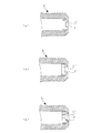
これに対し、本実施形態のガスボンベ開孔装置10は、ピストン30の復帰が生じなくとも、安定してガスボンベ5内のガスが噴出されるように、ピン部32及びヘッド部33に溝34を設け、ピン部32及びヘッド部33の溝34を連通させる構成とした。
そのため、本実施形態のガスボンベ開孔装置10では、ピストン30は、図3に示すように、ヘッド部33端面とガスボンベ5の封板7が接触した時点でピストン30の侵入を終了させ、ピストン30が復帰しなくとも、ピン部32及びヘッド部33の溝34をガスボンベ5内のガスが流れていく。
なお、ヘッド部33を設けない場合、ピン部32に溝34を設けても、ピン部32全体が封板7に刺さりガスボンベ5内に侵入した際は、ガスボンベ5内のガスが流れない。
In contrast, the gas
Therefore, in the gas
If the
ヘッド部33の径は封板7の穴径より大きく設定することで、ヘッド部33と封板7とが接触した時点でピストン30の侵入を終了させ、また、ヘッド部33とピン部32とを溝34で連通させることで、ガスボンベ5内のガスは、ガスボンベ5内に侵入したピン部32の溝部34からヘッド部33の溝34を介して流れる。つまりは、ピストン30が復帰せずとも、ガスボンベ5内のガス噴出流路を確保できる。
なお、ピストン30移動後は、ヘッド部33の溝34とホルダ21のガス放出穴24とが連通されることで、ガスボンベ5内のガスは、ホルダ21のガス放出穴24より噴出される。
よって、ホルダ21に設けるガス放出穴24は、ホルダ21軸に対し上下左右1箇所もしくは上下左右対称に、移動後のピストン30のヘッド部33に設けた溝34と連通する位置に設ける。なお、径としては3.0mm以上が望ましい。
By setting the diameter of the
After the movement of the
Therefore, the
また、ピストン30が復帰しない場合でも、ガスボンベ5の封板7の開孔部径が大きくなるほど、ガスボンベ5内からのガス噴出量は増加する。
ガスボンベ5の封板7は、ピン部32の形状に沿って開孔するが、ピン部32の径が太くなるほど、ピン部32が封板7に侵入した際、破断した封板7に対するピン部32側面側へのひずみが大きく加わる。
そのため、図18(a)〜(c)に示すように、ピン部32の径が太くなるほど、封板7の開孔部7’の径が大きくなり、また、破断した封板7には亀裂が生じていく。
開孔部7’の径が大きくなるほど、封板7の亀裂も増加する。破断した封板7の亀裂が増加することで、ピン部32と破断した封板7の隙間が多くなるため、ピストン30が復帰しない場合でも、ガスボンベ5内のガス噴出流路は増加する結果となる。
Even when the
The sealing
Therefore, as shown in FIGS. 18A to 18C, the larger the diameter of the
As the diameter of the
以上より、本実施形態のピストン30は、芯ずれ防止としてピン部32の角度を設ける際に、可能な限り開孔部7’の径が大きくなるよう角度を設定することでも、ガスボンベ5内のガス噴出時間がより早くなるよう調整できる。
それに加えて、ピストン30には、溝部34も設けることになる。
なお、溝部34は、ピストン30へ加工可能な範囲内で設定することができる。
例えば、図19に示すように、各種類毎のガスボンベ5の封板7穴径に対し、ピン部32の角度、ヘッド部33の径を決定したピストン30に、径xmm上の軸に径ymmの溝を角度Z°おきに、加工可能な寸法で取ることができる。
From the above, the
In addition, the
In addition, the
For example, as shown in FIG. 19, the angle of the
径x、径y及び角度Z°は、ピン部32及びヘッド部33の寸法により任意に変更できる。
角度Z°を90°とし溝34を4箇所設ける場合もあれば、角度Z°を120°とし溝34を3箇所設けることも可能である。
また、溝34に関しては、加工性を考慮し円形の例を示したが、円形に拘らず、任意の形状、例えば角状でも良い。
いずれの場合でも、可能な限り溝34が大きくなるよう設定すれば、ガスボンベ5内のガス噴出時間はより早くなる。
The diameter x, the diameter y, and the angle Z ° can be arbitrarily changed according to the dimensions of the
There are cases where the angle Z ° is 90 ° and four
Further, regarding the
In any case, if the
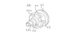
第2に、ピン部32にネジ切り加工を施し、ヘッド部33に溝34を設ける例について説明する。
図20、図21に示すように、ピン部32にネジ切り加工を施し、ヘッド部33に溝34を設けたピストン30も、ピストン30移動後に復帰が生じなくとも、ガスボンベ5内のガス噴出流路を形成できる。
ヘッド部33は封板7が接触した時点でピストン30の侵入を終了させ、ガスボンベ5内のガスは、ガスボンベ5内に侵入したピン部32のネジ切り加工部からヘッド部33の溝34を介して流れる。
つまりは、ピストン30が復帰せずとも、ガスボンベ5内のガス噴出流路が確保できる。
なお、ネジ山の設定は、ピン部32に加工可能な寸法内で任意に設けることができ、可能な限りガス噴出流路が最大になるよう設定すれば、ガスボンベ5内のガス噴出時間はより早くなる。
Secondly, an example in which the
As shown in FIGS. 20 and 21, the
The
That is, the gas ejection flow path in the
The screw thread can be arbitrarily set within the dimensions that can be machined in the
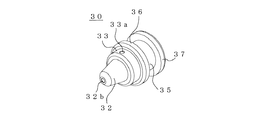
第3に、ピン部32に中空穴32bを設け、ヘッド部33はピン部32の中空穴32bと垂直方向に貫通穴33aを設け、ピン部32の中空穴32bとヘッド部33の貫通穴33aを連通させる。
先行技術(特許文献4)には、機械式のボンベ開封方法として、中空針にスリットを設けた針を使用する実施形態が挙げられている。
この形状のピストンを薬剤燃焼時のガスにより加圧しボンベ封板を開孔すると、中空部より圧漏れが生じる。
また、中空の針では、ガスボンベ開孔後ピストンが復帰しない場合、ガスボンベ内のガスは、ガス発生器側へ放出される。
Third, a hollow hole 32 b is provided in the
In the prior art (Patent Document 4), an embodiment using a needle provided with a slit in a hollow needle is given as a mechanical cylinder opening method.
When the piston of this shape is pressurized with the gas during chemical combustion and the cylinder sealing plate is opened, pressure leakage occurs from the hollow portion.
In the case of a hollow needle, if the piston does not return after opening the gas cylinder, the gas in the gas cylinder is released to the gas generator side.
これに対し、本実施形態のピストン30は、図22、図23に示すように、ピン部32に中空穴32bを設け、ヘッド部33にはピン部32の中空穴32bと垂直方向に貫通穴33aを設け、ピン部32の中空穴32bとヘッド部33の貫通穴33aを連通させる構造とした。
ピン部32に中空穴32bを設け、ヘッド部33にはピン部32の中空穴32bと垂直方向に貫通穴33aを設けることで、ピストン30のOリング装着部35に貫通穴は生じないため、薬剤燃焼時のガスによりピストン30は圧漏れが生じることなく加圧される。
また、ヘッド部33は封板7が接触した時点でピストン30の侵入を終了させ、ガスボンベ5内のガスは、ガスボンベ5内に侵入したピン部32の中空穴32bからヘッド部33の貫通穴33aを介して流れる。つまりは、ピストン30が復帰せずとも、ガスボンベ5内のガス噴出流路が確保できることになる。
On the other hand, as shown in FIGS. 22 and 23, the
By providing a hollow hole 32b in the
Further, the
なお、ピン部32の中空穴32bの穴径の設定は、ピン部32に加工可能な寸法内で任意に設けることができる。
また、ヘッド部33の貫通穴33aの設定も、貫通穴33aの穴径はヘッド部33に加工可能な寸法内で任意に設けることができ、その穴数も1箇所に限らず、ヘッド部33に加工可能な範囲内で、貫通穴33aが交差するよう数本設けることが可能である。
中空穴32b及び貫通穴33aの設定時も、可能な限りガス噴出流路が最大になるよう設定すれば、ガスボンベ5内のガス噴出時間はより早くなる。
In addition, the setting of the hole diameter of the hollow hole 32b of the
In addition, the through hole 33a of the
Even when the hollow hole 32b and the through hole 33a are set, the gas ejection time in the
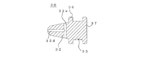
次に、ヘッド部33を設けない場合のピストン30の形状について説明する。
先ず、ピン部32の終端径をガスボンベ5の封板7の穴径以上に設定したピストン30について説明する。
図24は、ピン部32に溝加工を施して溝34を形成した例、図25は、ピン部32にネジ切り加工を施して螺旋部32cを形成した例、図26は、ピン部32に中空穴32d、貫通穴32eを形成した例を示す。
ピン部32の終端径を封板7の穴径以上に設定することで、ピストン30の侵入は、封板7の穴径以上のピン部32の断面径の位置に達した時点で終了となる。
その際でも、ピン部32に設ける溝34や螺旋部32cは、ピン部32の終端部まで設ける。
Next, the shape of the
First, the
24 shows an example in which
By setting the terminal diameter of the
Even in this case, the
また、ピン部32に中空穴32d、貫通穴32eを設ける場合は、初めにガスボンベ5内に侵入する位置まで中空穴32dを設け、ガスボンベ5の外部に露出する位置へ、ガスボンベ5内侵入位置まで設けた中空穴32dと垂直方向に中空穴32eを設け、各中空穴32d,32eは連通させる構造とする。
ピン部32の終端径を封板7の穴径以上に設定することで、図27に示すように、ピストン30の侵入はピン部32の途中で終了する。
Further, when the
By setting the terminal diameter of the
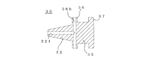
次に、ピン部32の終端径をガスボンベ5の封板7の穴径以下に設定し、Oリング装着部35の壁部36を封板7の穴径以上に設定したピストン30について説明する。
ピン部32の終端径をガスボンベ5の封板7の穴径以下に設定することで、図28に示すように、ピン部32は完全にガスボンベ5内に侵入し、Oリング装着部35の壁部36を封板7の穴径以上に設定することで、ピストン30の侵入は、ガスボンベ5の封板7とOリング装着部35の壁部36が接触した時点で終了となる。
なお、この場合は、図29に示すように、ピン部32に溝34を加工を施し、Oリング装着部35の壁部36には切欠部36aを設ける。或いは、図31に示すように、ピン部32から壁部36に亘って中空穴32f、貫通穴36bを設けることで、ガスボンベ5内のガス噴出流路を形成させる。
Next, the
By setting the terminal diameter of the
In this case, as shown in FIG. 29, a
例えば、ピン部32に溝34を設ける場合は、図29に示すように、ピン部32に設けた溝34と連通するように、Oリング装着部35の壁部36に切欠部36aを設ける。
また、例えば、図30に示すように、ピン部32にネジ切り加工を施して螺旋部32cを形成した場合は、ピン部32の螺旋部32cと連通するようにOリング装着部35の壁部36に切欠部36aを設ける。
一方で、図31に示すように、ピン部32に中空穴32fを設けた場合は、ピン部32の中空穴32fと垂直方向にOリング装着部35の壁部36に貫通穴36bを設け、中空穴32f及び貫通穴36bは連通させる構造とする。
For example, when providing the
For example, as shown in FIG. 30, when the
On the other hand, as shown in FIG. 31, when a hollow hole 32f is provided in the
以上の構造とすることで、Oリング装着部35の壁部36がガスボンベ5の封板7を塞いでも、ガスボンベ5内のガスは噴出させることが可能となる。
なお、切欠部36aの形状については、円形、角状を問わず、加工上可能な範囲で設定できる。
また切欠形状のみでなく、図32に示すように、Oリング装着部35の壁部36に溝36cを設ける加工でも良い。
Oリング装着部35への溝36cの設け方も、加工可能な範囲であれば、任意の形状にできる。
With the above structure, even if the
In addition, about the shape of the notch part 36a, it can set in the range which can be processed regardless of circular and square shape.
In addition to the notch shape, as shown in FIG. 32, a process may be performed in which a groove 36c is provided in the
The method of providing the groove 36c in the O-
(実験例)
先行技術では、ホルダ21のピストン案内穴25よりピストン30の外径を小さくすることで、ガス発生剤44の圧力がホルダ21のガス放出穴24より噴出され、ピストン30の復帰がスムースになると考えられている(ガス発生剤のガスが蓄圧されると、ピストンが戻りにくいとの考えより)。
そこで、先ず初めに、図33に示すように、ガス抜き穴26を設けずピストン案内穴25の径を6mmとしたステンレス製のホルダ21Aと、Oリング装着部35を設けずピストン30Aの外径を5.8mmとしたガスボンベ開孔装置10Aの作動確認を実施した。
ホルダ21Aのガス放出穴24の径は3mmである(以降の全試験、ホルダ21Aのガス放出穴24の径は3mmとなる)。
(Experimental example)
In the prior art, by making the outer diameter of the
Therefore, as shown in FIG. 33, first, as shown in FIG. 33, the stainless steel holder 21A in which the diameter of the
The diameter of the
試験で使用したガスボンベ5は、日本炭酸瓦斯株式会社製のミニガスカートリッジ(型式:LS20−1−16g)であり、ガスボンベ内には液化CO2ガスが約16g充填されている(以降の全試験にて、同ガスボンベを使用している)。
ガスボンベ概要は、下記の通りである。
製品名:ミニガスカートリッジ、メーカー:日本炭酸瓦斯株式会社製、型番:LS20−1−16g、CO2質量:16.0±1.0g、封板厚さ:0.23±0.05mm
ガスボンベ5の封板7の穴最大径は3.5mmであるため、封板7の開孔部径は最大でも3.5mmとなる。
The
The outline of the gas cylinder is as follows.
Product Name: mini gas cartridge, Studio: Japan carbonate gas Co., Ltd., model number: LS20-1-16g, CO 2 mass: 16.0 ± 1.0g, Fuban thickness: 0.23 ± 0.05mm
Since the maximum hole diameter of the sealing
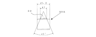
そこで、図35に示すように、ステンレス製のピストン30Aのピン部32は芯ずれが生じても封板7にピン部32が刺さるよう、ピン部32の先端から終端の角度は46°に設定してピン部32の先端を尖らせ、終端部径を3mmとしたピストン30Aを用いた。
なお、試験時の非火薬ガス発生剤は、薬量0.1gと薬量0.2gの2水準について実施した。ただし、点火薬量は、0.15gと固定している(以降の全試験、点火薬量は0.15gとなる)。
シート29は、ポリエステル樹脂で構成され、外径が5.5mm、厚さが0.3mmである。
Therefore, as shown in FIG. 35, the
In addition, the non-explosive gas generating agent at the time of a test was implemented about two levels, the dosage 0.1g and the dosage 0.2g. However, the amount of the ignition charge is fixed at 0.15 g (all the subsequent tests, the amount of the ignition charge is 0.15 g).
The
(1)確認方法
確認項目としては、装置作動後のピストン復帰状況、CO2ガスの噴出時間、ガスボンベ5の封板7の開孔部径の測定を実施した。
CO2ガス噴出時間は、ビデオカメラにて撮影した動画より、ガス噴出開始から噴出終了までの時間を計測した。
また、ガスボンベ5の封板7はピン形状に沿って開孔し、ピン部32の先端側と終端側で封板7の開孔部径は異なるが、本試験ではピン部32の先端側(ガスボンベ5内)の開孔部径を株式会社キーエンス製マイクロスコープVHX−100にて測定した。
(1) Confirmation method As confirmation items, the piston return status after the operation of the device, the CO 2 gas ejection time, and the diameter of the opening of the sealing
The CO 2 gas jetting time was measured from the video shot with a video camera from the gas jetting start to the jetting end.
Further, the sealing
(2)確認結果
作動確認結果を表3に示す。
本試験では、ピストン30Aのピン部32が、ガスボンベ5内に完全に侵入していない状況であった。
ただし、ピン部32が僅かではあるがガスボンベ5内に侵入はしたため、薬量0.1g及び0.2gともに、ガスボンベ5の封板7は開孔した。また、薬量が多い方がピン部32がより深くガスボンベ5内に侵入したため、封板7の開孔部径は大きくなった。封板7の関孔後、ピストン30Aは復帰せず、封板7の開孔部をピン部32が塞いだため、CO2ガスは噴出されない結果となった。
よって、ピストン案内穴25よりピストン30Aの外径を小さくし、残圧を放出する構造にしても、ピストン30Aは復帰しないといえる。
In this test, the
However, since the
Therefore, even if the outer diameter of the piston 30A is made smaller than the
ピストン30Aの復帰は、ガスの蓄圧のみでなく、ガス発生剤燃焼後に生じる固形残渣がピストン30Aの外周部に付着することで、復帰しにくい状況を作り出していると予測できる。
以上の結果より、ホルダ21Aのピストン案内穴25よりピストン30Aの外径を小さくすることに効果はなく、寧ろ、ガス発生剤燃焼時にピストン30Aに作用する圧力がクリアランスより漏れることで、ピストン30Aを押す圧力が低下するデメリットの方が大きいと考えられる。
The return of the piston 30A can be predicted not only to accumulate the gas pressure but also to create a situation in which the solid residue generated after the combustion of the gas generating agent adheres to the outer peripheral portion of the piston 30A and is difficult to return.
From the above results, there is no effect in reducing the outer diameter of the piston 30A from the
次に、圧漏れの対策として、図36、図37に示すように、ピストン30AにOリング装着部35を設け、サイズS4のOリング38を装着したピストン30Bを用いた場合のガスボンベ開孔装置10Aの作動状況を確認した。
本試験と上記試験で異なる部品としては、ピストンのみである。
Oリング38を装着したピストン30Bについて、ガス発生剤薬量を0.2gとし、装置作動後のピン復帰状況、CO2ガスの噴出時間、ガスボンベ5の封板7の開孔部径の測定を実施した。
なお、試験はN=2確認を行った。
作動確認結果を表4に示す。
Next, as a countermeasure against pressure leakage, as shown in FIGS. 36 and 37, a gas cylinder opening device in which an O-
The only part that differs between this test and the above test is the piston.
For the piston 30B equipped with the O-
In the test, N = 2 was confirmed.
Table 4 shows the operation confirmation results.
Oリング38を装着することで、ピストン30Bのピン部32が、ガスボンベ5内に完全に侵入し、封板7の開孔部径は大きくなった。
ガスボンベ5の封板7を径1.6mm開孔するのに必要な力Fは、打ち抜き力の計算式(F=2π×打ち抜き半径r×封板厚さt×封板材料せん断抵抗τ)より、31.5kgfと求まる。
よって、ガスボンベ5の封板7を1.6mm開孔させるのに必要なピストン30Bへ与える圧力Pは、ガスボンベ5の封板7を開孔させるのに必要な力Fをピストン30Bの受圧面積で割ることで、119.3(kgf/cm2)となる。
この119.3(kgf/cm2)という圧力を発生させるのに必要なガス発生剤薬量は、ホルダ21Aのピストン案内穴25の容積を加味し、最低0.1g以上であれば十分である。
By mounting the O-
The force F required to open the sealing
Therefore, the pressure P applied to the piston 30B required to open the sealing
The gas generating agent dose required to generate the pressure of 119.3 (kgf / cm 2 ) is sufficient if it takes into account the volume of the
それに対し、ピストン30BにOリング38を装着しない場合は、ガス発生剤薬量0.2gでもピストン30Bのピン部32が完全にガスボンベ5内には侵入せず、封板7の開孔部径は小さくなった。
一方で、ピストン30BにOリング38を装着すれば、ピストン30Bのピン部32がガスボンベ5内に完全に侵入し、封板7の開孔部径としても適切な値が得られた。
よって、ピストン30BにOリング38を装着しない場合は、ホルダ21Aのピストン案内穴25とピストン30Bとのクリアランス部より圧漏れが生じていると判断できる。
以上より、Oリング38を装着することで、圧漏れが防止されピストン30Bを押す圧力が向上した。
なお、本試験でも作動後にピストン30Bが復帰することはなかったが、CO2ガスが噴出される場合が観測された。
On the other hand, when the O-
On the other hand, when the O-
Therefore, when the O-
From the above, by attaching the O-
In this test, the piston 30B did not return after operation, but a case where CO 2 gas was ejected was observed.
ここで、CO2ガスが噴出したガスボンベ5を分解し、封板7の状況を観測した結果、「破断した封板に亀裂が生じている」といった特徴が確認できた。
Oリング38を装着せずピン部32が僅かしかガスボンベ5内に侵入しなかった条件に比べ、本試験時はピン部32が完全にガスボンベ5内に侵入したことで、ガスボンベ5内に侵入するピン部32の断面径は大きくなる。よって、ピン部32が封板7に侵入した際、破断した封板7へは、ピン側面側へのひずみがより大きく加わり、封板7の開孔部径が増加するとともに、破断した封板には亀裂が生じた。
上記の作用により、破断した封板7に亀裂が生じたため、ピン部32と破断した封板7の間には隙間が生じ、CO2ガスの噴出流路が形成された。
Here, as a result of disassembling the
Compared to the condition in which the O-
Due to the above action, the fractured
次に、ピストン形状による効果の確認について説明する。
ここまでの結果より、封板7の開孔部の径が大きくなれば、封板7に亀裂が大きく生じていき、ピン部32と破断した封板7の隙間よりCO2ガスの噴出流路が確保される。
また、封板7はピン形状に沿って開孔される。
よって、ピン部32の径を太くするほど、封板7の開孔部径は大きくなり、破断した封板7にはより多くの亀裂が生じ、CO2ガスの噴出には有利になる。
ただし、ピン部32の径を太くするため、ピン部32の先端側を尖らせず、ピン部32の先端部から終端部までストレートの形状とした場合、封板7の穴径とピン部32の径の設定次第では、ピストン移動時に芯ずれが生じた場合、ピン部32が封板7の穴に刺さらず、ピストンが移動しない状況が生じる。
Next, confirmation of the effect of the piston shape will be described.
From the results up to this point, if the diameter of the opening portion of the sealing
Further, the sealing
Therefore, the larger the diameter of the
However, in order to increase the diameter of the
この問題に対しては、「ピン先端側には一定の角度を付ける」又は、「ピン先端側から終端側にかけてピン部全体的に一定の角度を付ける」或いは、「ピン先端側から一定の角度を付け、且つ、ピン部中間から終端部にかけて、ピン先端側に設けた角度より小さい角度を付ける」ことで、ピストンの芯ずれを修正できる。尚且つ、角度設定時は、ピン部径が大きくなるよう設定することで、封板開孔部径を大きくすることが可能である。
また、ピストンが復帰しなくとも、ピストンからホルダ21Aのガス放出穴24にかけてCO2ガス噴出流路が形成されれば、ピストンの復帰に依らず、CO2ガスは噴出される。
以上の効果を得られるピン形状として、以下の2種類のピストンA,Bについて作動確認を実施した。
For this problem, “make a certain angle on the pin tip side” or “make a certain angle for the entire pin part from the pin tip side to the terminal end” or “a certain angle from the pin tip side” And an angle smaller than the angle provided on the pin tip side from the middle of the pin portion to the end portion is given, whereby the misalignment of the piston can be corrected. In addition, when setting the angle, it is possible to increase the diameter of the sealing plate opening by setting the pin part diameter to be large.
Even if the piston does not return, if a CO 2 gas injection passage is formed from the piston to the
Operation confirmation was carried out for the following two types of pistons A and B as pin shapes that can achieve the above effects.
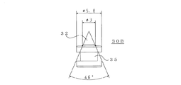
ピストンAは、図38、図39に示すように、ピン部32の先端は平坦形状とし、ピン部32の終端部径を3mm、ピン部32の先端部から終端部にかけて37°の角度を付け、更にヘッド部33を設け、ピン部32の終端からヘッド部33にかけて連通する溝34を90°おきに設けた。
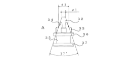
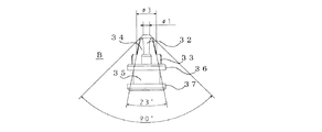
ピストンBは、図40、図41に示すように、ピン部32の先端は平坦形状とし、ピン部32の終端部径を3mm、ピン部32の先端部から90°の角度を付け、更にピン部32の中間からピン部32の終端部までは23°の角度を付け、更にヘッド部33を設け、ピン部32の先端からヘッド部33にかけて連通する溝34を90°おきに設けた。
2種類のピストンA,Bは、ピン部32の先端が平坦形状である。
As shown in FIGS. 38 and 39, the piston A has a flat tip at the tip of the
In the piston B, as shown in FIGS. 40 and 41, the tip of the
In the two types of pistons A and B, the tip of the
ピン部32の先端が平坦になることで、ピン部32の全長が短くなり、ピストンA,Bの小型化に繋がり、最終的にはガスボンベ開孔装置の小型化に繋がる。
また、振動や衝撃によりガスボンベ5の封板7を損傷する危険性を低下できる。
なお、ピン部32の先端部径は1mmであり、ガスボンベ5の封板7の穴最大径3.5mmより小さいため、ピストン移動時に芯ずれが生じてもピン部32の先端はガスボンベ5の封板7に刺さる。
また、ピン部32の先端には傾斜を設けているため、ピストンA,Bの進行とともにピストンの芯ずれが修正される。
なお、ピストンBは、ピストンAと比較し、ピン部32の終端側の角度は小さくなっている。
そのため、ピストンBの方が、ガスボンベ5内に侵入するピン部32の断面径は大きくなることで、ガスボンベ5の封板7の開孔部径は大きくなる。
By flattening the tip of the
Further, the risk of damaging the
Since the tip diameter of the
Further, since the tip of the
The piston B has a smaller angle on the terminal side of the
Therefore, in the piston B, the diameter of the opening portion of the sealing
更に、2種類のピストンA,Bには、ピン部32からヘッド部33にかけて溝34を設けた。
溝34の寸法は、図19に示す溝部寸法と同様に、ピストンA,Bともに、径x=4mm上の軸に、径y=2mmの溝を、角度Z=90°おきに4箇所設けている。
ピストンA,Bに設けたヘッド部33は、封板7と接触した時点でピン部32の侵入を終了させ、また、ヘッド部33及びピン部32の溝34が連通しているので、ガスボンベ5内に侵入したピン部32の溝34からヘッド部33の溝34までCO2ガスの流路が確保できる。
ピストン移動後は、ヘッド部33の溝34とホルダ21Aのガス放出穴24が連通され、CO2ガスは、ホルダ21Aのガス放出穴24より噴出される。
Further, the two types of pistons A and B are provided with a
The dimensions of the
The
After the piston movement, the
また、2種類のピストンA,Bは、Oリング38を取り付ける構造とした。
既に述べたとおり、ピストンA,BにOリング38を取り付けることで、非火薬ガス発生剤燃焼時の圧漏れを防ぎ、ピストンを押す圧力が向上する。
ただし、Oリング38を設けた場合、ピストン移動後、非火薬ガス発生剤の残圧が開放されない状況が生じる。
そこで、図1、図2,図5に示すように、ホルダ21にはピストン移動後の残圧開放として、ピストン移動後にOリング38直後方となる位置に、穴径1.0mmのガス抜き穴26を設けた。
Further, the two types of pistons A and B have a structure in which an O-
As already described, by attaching the O-
However, when the O-
Therefore, as shown in FIG. 1, FIG. 2, and FIG. 5, the
(1)作動確認
ガス抜き穴26を設けたホルダ21を使用し、ピストンA及びBを配置した装置の作動確認を実施した。
確認項目は、装置作動後のピストン復帰状況、ガスボンベ5の封板7の開孔部径(mm)の測定、CO2ガスの噴出時間(ms)である。
封板7の開孔部径は、ピン先端側(ガスボンベ内)の関孔部径を株式会社キーエンス製マイクロスコープVHX−100にて測定している。
CO2ガス噴出時間は、高速度カメラにて撮影した動画より、ガス噴出開始から噴出終了までの時間を計測した。
ガス発生剤薬量は、0.1gと0.2gの2水準とし、各水準についてN=3計測を行った。
(1) Confirmation of operation Using the
The confirmation items are the piston return status after the operation of the apparatus, the measurement of the diameter (mm) of the opening of the sealing
The diameter of the hole in the sealing
The CO 2 gas jetting time was measured from the video shot with a high-speed camera from the gas jetting start to the jetting end.
The amount of gas generating agent was set to two levels of 0.1 g and 0.2 g, and N = 3 was measured for each level.
(2)確認結果
計測結果を表5に示す。
全試験試料において、ピストンA,Bのピン部32はガスボンベ5内に完全に侵入した。
ガス発生剤薬量を0.2gとした場合、ピン部32の先端とガスボンベ5の間に配置しているシート29が、ガス発生剤薬量0.1g時より多く潰れるため、ピン部32がより深くガスボンベ5内に侵入し、封板7の開孔部径が増加する結果も得られた。
ガス発生剤薬量を0.1gとした場合は、ピストン30が復帰し、ガス噴出時間が短くなることも確認できた。
これまでの試験と比較し、本試験時は、封板7の間孔部径が大きくなったため、ガスボンベ5内のガスがピストン30を復帰させる方向へ強く働き、ピストン30の復帰が生じるようになったと考えられる。
ただし、ガス発生剤薬量を増加させると、燃焼後の残渣量も増えるため、ピストン30は復帰しなくなる。
In all the test samples, the
When the gas generating agent dose is 0.2 g, the
It was also confirmed that when the gas generating agent dose was 0.1 g, the
Compared with the previous tests, the hole diameter of the sealing
However, if the amount of gas generating agent is increased, the amount of residue after combustion also increases, so the
ピストンAとピストンBとの封板7の開孔部径を見ると、ピストンBの方がより大きな開孔部径となる結果であった。
よって、ピン部32の終端側の角度は小さくすることで、より大きく封板7を開孔可能であることが実証できた。
更に、ピストンAとピストンBとのガス発生剤薬量0.2g時の結果より、ピストン30が復帰しなくとも、ガスボンベ5内のガス噴出時間は安定することも確認できた。
以上より、ピストン30が復帰しなくとも、ピストン30からホルダ21のガス放出穴24にかけてCO2ガス噴出流路が形成されれば、ピストン30の復帰に依らず、CO2ガスは噴出される。
The opening diameter of the sealing
Therefore, it was proved that the sealing
Further, from the result of the gas generating agent dose amount of 0.2 g of the piston A and the piston B, it was confirmed that the gas ejection time in the
As described above, even if the
ピストンBの方が、ガス噴出時間は早くなる。
その理由としては、ピストンBの方がピン部32の終端側の角度は小さく、封板7の開孔部径が大きくなり、破断した封板7にはより多くの亀裂が生じたため、ピストン30の溝34の他に、破断した封板7とピン部32との隙間が大きくなり、CO2ガス噴出流路が増加したためと考えられる。
よって、ピストン30は、芯ずれ修正としてピンに角度を設ける際に、可能な限り開孔部径が大きくなるよう角度を設定し、且つ、ピン部32からヘッド部33まで加工可能な範囲で噴出流路が大きくなるよう設定することにより、ピストン30が復帰しなくとも、ガスボンベ5内のガス噴出時間がより早くなるよう調整できる。
The piston B has a faster gas ejection time.
The reason for this is that the piston B has a smaller angle on the terminal end side of the
Therefore, when the
1 膨張ユニット
2 開口部
3 プレート
4 ワッシャ
5 ガスボンベ
6 口部
7 封板
10 ガスボンベ開孔装置
20 ガスボンベ開孔器
21 ホルダ
22 ガスボンベ取付穴
23 ガス発生器取付穴
24 ガス放出穴
25 ピストン案内穴
26 ガス抜き穴
29 シート
30 ピストン
32 ピン部
32a ピン部32の先端
32b,32d,32f 中空穴
32c 螺旋部
32e,33a,36b 貫通穴
33 ヘッド部
34,36c 溝
35 Oリング装着部
36,37 壁部
36a 切欠部
38 Oリング
40 ガス発生器
40a ガス発生部
41 ホルダ
43 管体
44 ガス発生剤
45 キャップ
46 点火薬ホルダ
47 点火薬
48 電橋線付塞栓
49 電橋線
50 シール剤
DESCRIPTION OF
Claims (15)
前記封鎖部に装着され、前記ガスボンベの口部を装着し、前記ガスボンベの封板を開孔し、前記ガスボンベ内のガスを前記膨張ユニット内に噴出させる開孔器と、
前記開孔器に装着された前記ガスボンベの封板の前面に配されるシートと、
前記ガスボンベの口部と対向して前記開孔器に装着され、非火薬組成部物から成るガス発生剤の燃焼によってガス圧を発生するガス発生器と、
前記開孔器内で前記シートと前記ガス発生器との間に配され、前記ガス発生器のガス圧によって前記封板を開孔するピストンと
を備え、
前記開孔器は、前記封鎖部に装着される装着部と、前記ガスボンベの口部を装着するガスボンベ取付部と、前記ピストンを配するピストン案内穴と、前記ガス発生器を装着するガス発生器取付部と、前記ピストン案内穴と連通するガス放出穴と、前記ピストン案内穴と連通し、前記ガス放出穴と離間して設けられるガス抜き穴とを備え、
前記ピストンは、ガス噴出流路を備え、前記封板を開孔するピン部と、前記ピストン案内穴の内壁に密着されるOリングを装着するOリング装着部とを備え、
前記ガス発生器の作動前は、前記ピストンは、前記ピン部が前記シートの前面に位置し、前記Oリング装着部が前記ガス抜き穴より前記ガス発生器側に位置し、
前記ガス発生器の作動後は、前記ピストンは、前記ガス発生剤の燃焼によるガス圧によって前記ガスボンベの口部側へ押し出され、前記Oリング装着部が前記ガス抜き穴より前記ガスボンベの口部側へ移動し残圧を前記ガス抜き穴から放出し、前記ピン部が前記シート及び前記封板を刺して前記ガスボンベの口部内に侵入し、前記ガス噴出流路を介して前記ガスを前記ガス放出穴から噴出して前記膨張ユニットを展開する
ことを特徴とするガスボンベ開孔装置。 A gas cylinder opening for opening a sealing plate provided at the mouth of a gas cylinder arranged in a deployable expansion unit that seals the opening with a sealing part, and for discharging the gas in the gas cylinder to expand the expansion unit In the device
An opening device that is attached to the sealing part, attaches the opening of the gas cylinder, opens the sealing plate of the gas cylinder, and ejects the gas in the gas cylinder into the expansion unit;
A sheet disposed on the front surface of the sealing plate of the gas cylinder mounted on the aperture;
A gas generator that is mounted on the opener facing the mouth of the gas cylinder and generates a gas pressure by combustion of a gas generating agent comprising a non-explosive composition part;
A piston disposed between the sheet and the gas generator in the aperture, and opening the sealing plate by a gas pressure of the gas generator;
The opening device includes a mounting portion to be mounted on the blocking portion, a gas cylinder mounting portion for mounting a mouth portion of the gas cylinder, a piston guide hole for arranging the piston, and a gas generator for mounting the gas generator. A mounting portion; a gas discharge hole communicating with the piston guide hole; and a gas vent hole communicating with the piston guide hole and spaced apart from the gas discharge hole.
The piston includes a gas ejection channel, and includes a pin portion that opens the sealing plate, and an O-ring mounting portion that mounts an O-ring that is in close contact with the inner wall of the piston guide hole,
Before the operation of the gas generator, the pin of the piston is located on the front surface of the seat, and the O-ring mounting part is located on the gas generator side from the gas vent hole,
After the operation of the gas generator, the piston is pushed out to the mouth side of the gas cylinder by the gas pressure due to combustion of the gas generating agent, and the O-ring mounting part is on the mouth side of the gas cylinder from the gas vent The residual pressure is released from the gas vent hole, the pin portion pierces the sheet and the sealing plate and enters the mouth of the gas cylinder, and the gas is released through the gas ejection channel. A gas cylinder opening device, wherein the expansion unit is expanded by being ejected from a hole.
前記ピストンは、前記ガス噴出流路を備え、前記ガスボンベの封板を開孔し前記ガスボンベの口部内に侵入するピン部と、前記Oリングを取り付け、前記ガスボンベの封板に接触した時点で前記ピン部の侵入を終了させるOリング装着部とを備える
ことを特徴とするガスボンベ開孔装置。 In the gas cylinder opening device according to the invention of claim 1,
The piston includes the gas ejection flow path, and a pin portion that opens the sealing plate of the gas cylinder and enters the mouth portion of the gas cylinder, and the O-ring is attached, and when the piston contacts the sealing plate of the gas cylinder, A gas cylinder opening device, comprising: an O-ring mounting portion that terminates intrusion of the pin portion.
前記ガス噴出流路は、前記ピン部の長手方向に溝を設けることによって構成される
ことを特徴とするガスボンベ開孔装置。 In the gas cylinder opening device according to the invention of claim 2,
The gas jet passage device is configured by providing a groove in the longitudinal direction of the pin portion.
前記ガス噴出流路は、前記ピン部の長手方向に溝を設け、前記Oリング装着部の壁部に前記溝に連なる切欠部を設けることによって構成される
ことを特徴とするガスボンベ開孔装置。 In the gas cylinder opening device according to the invention of claim 2,
The gas ejection passage is configured by providing a groove in the longitudinal direction of the pin portion and providing a notch portion continuous with the groove in a wall portion of the O-ring mounting portion.
前記ガス噴出流路は、前記ピン部にネジ切り加工を施して螺旋部を形成することによって構成される
ことを特徴とするガスボンベ開孔装置。 In the gas cylinder opening device according to the invention of claim 2,
The gas jet passage device is configured by forming a spiral portion by subjecting the pin portion to threading.
前記ガス噴出流路は、前記ピン部にネジ切り加工を施して螺旋部を形成し、前記Oリング装着部の前記ピン部側壁部に前記溝に連なる切欠部を設けることによって構成される
ことを特徴とするガスボンベ開孔装置。 In the gas cylinder opening device according to the invention of claim 2,
The gas ejection flow path is configured by forming a spiral portion by threading the pin portion, and providing a notch portion continuous with the groove on the pin portion side wall portion of the O-ring mounting portion. A gas cylinder hole opening device.
前記ガス噴出流路は、前記ピン部に軸長方向に中空部を設けると共に、前記中空部と垂直方向に前記中空部と連通する貫通穴を設けることによって構成される
ことを特徴とするガスボンベ開孔装置。 In the gas cylinder opening device according to the invention of claim 2,
The gas ejection flow path is configured by providing a hollow portion in the axial direction in the pin portion and providing a through hole communicating with the hollow portion in a direction perpendicular to the hollow portion. Hole device.
前記ガス噴出流路は、前記ピン部に軸長方向に中空部を設け、前記Oリング装着部の前記ピン部側壁部に前記中空部と垂直方向に前記中空部と連通する貫通穴を設けることによって構成される
ことを特徴とするガスボンベ開孔装置。 In the gas cylinder opening device according to the invention of claim 2,
The gas ejection flow path is provided with a hollow portion in the axial direction in the pin portion, and a through hole communicating with the hollow portion in a direction perpendicular to the hollow portion is provided in a side wall portion of the pin portion of the O-ring mounting portion. A gas cylinder opening device characterized by comprising:
前記ピストンは、前記ガス噴出流路を備え、前記ガスボンベの封板を開孔し前記ガスボンベ内に侵入するピン部と、前記ガスボンベの封板に接触した時点で前記ピン部の侵入を終了させるヘッド部と、前記Oリングを取り付けるOリング装着部とを備える
ことを特徴とするガスボンベ開孔装置。 In the gas cylinder opening device according to the invention of claim 1,
The piston includes the gas ejection flow path, and has a pin portion that opens the sealing plate of the gas cylinder and enters the gas cylinder, and a head that terminates the penetration of the pin portion when contacting the sealing plate of the gas cylinder A gas cylinder hole opening device comprising: an O-ring mounting portion for attaching the O-ring;
前記ピン部は、先端を平坦又は球状にし、前記先端側から19°〜130°の角度を付ける斜面を備える
ことを特徴とするガスボンベ開孔装置。 In the gas cylinder opening device of the invention according to claim 9,
The said pin part is equipped with the inclined surface which makes a front-end | tip flat or spherical, and makes the angle of 19 degrees-130 degrees from the said front end side. The gas cylinder opening apparatus characterized by the above-mentioned.
前記ピン部は、先端を平坦又は球状にし、前記先端側から終端部にかけて、10°〜95°の角度を付ける斜面を備える
ことを特徴とするガスボンベ開孔装置。 In the gas cylinder opening device of the invention according to claim 9,
The said pin part is equipped with the inclined surface which makes a front-end | tip flat or spherical, and makes the angle of 10 degrees-95 degrees from the said front end side to a termination | terminus part. The gas cylinder opening apparatus characterized by the above-mentioned.
前記ピン部は、先端を平坦又は球状にし、前記先端側から19°〜130°の角度を付ける斜面を備え、前記ピン部中間から終端部にかけて、前記先端側に設けた角度より小さい角度を付ける斜面を備える
ことを特徴とするガスボンベ開孔装置。 In the gas cylinder opening device of the invention according to claim 9,
The pin portion has a slope that makes the tip flat or spherical and has an angle of 19 ° to 130 ° from the tip side, and has an angle smaller than the angle provided on the tip side from the middle of the pin portion to the terminal portion. A gas cylinder opening device comprising a slope.
前記ガス噴出流路は、前記ピン部及び前記ヘッド部に溝を設け、前記ピン部及び前記ヘッド部の溝を連通させることによって構成される
ことを特徴とするガスボンベ開孔装置。 In the gas cylinder opening device of the invention according to claim 9,
The gas ejection passage is configured by providing a groove in the pin portion and the head portion and communicating the groove of the pin portion and the head portion.
前記ガス噴出流路は、前記ピン部にネジ切り加工を施して螺旋部を形成し、前記ヘッド部に溝を設け、前記螺旋部と前記溝とを連通させることによって構成される
ことを特徴とするガスボンベ開孔装置。 In the gas cylinder opening device of the invention according to claim 9,
The gas ejection flow path is formed by threading the pin portion to form a spiral portion, providing a groove in the head portion, and communicating the spiral portion and the groove. Gas cylinder opening device.
前記ガス噴出流路は、前記ピン部に中空部を設け、前記ヘッド部は前記ピン部の中空部と垂直方向に貫通穴を設け、前記ピン部の中空部と前記ヘッド部の貫通穴とを連通させることによって構成される
ことを特徴とするガスボンベ開孔装置。
In the gas cylinder opening device of the invention according to claim 9,
The gas ejection flow path has a hollow portion in the pin portion, the head portion has a through hole in a direction perpendicular to the hollow portion of the pin portion, and the hollow portion of the pin portion and the through hole of the head portion A gas cylinder opening device characterized by being configured to communicate with each other.
Priority Applications (1)
| Application Number | Priority Date | Filing Date | Title |
|---|---|---|---|
| JP2013020304A JP5980696B2 (en) | 2013-02-05 | 2013-02-05 | Gas cylinder opening device |
Applications Claiming Priority (1)
| Application Number | Priority Date | Filing Date | Title |
|---|---|---|---|
| JP2013020304A JP5980696B2 (en) | 2013-02-05 | 2013-02-05 | Gas cylinder opening device |
Publications (2)
| Publication Number | Publication Date |
|---|---|
| JP2014151663A true JP2014151663A (en) | 2014-08-25 |
| JP5980696B2 JP5980696B2 (en) | 2016-08-31 |
Family
ID=51573980
Family Applications (1)
| Application Number | Title | Priority Date | Filing Date |
|---|---|---|---|
| JP2013020304A Active JP5980696B2 (en) | 2013-02-05 | 2013-02-05 | Gas cylinder opening device |
Country Status (1)
| Country | Link |
|---|---|
| JP (1) | JP5980696B2 (en) |
Cited By (6)
| Publication number | Priority date | Publication date | Assignee | Title |
|---|---|---|---|---|
| CN107856822A (en) * | 2017-11-09 | 2018-03-30 | 方俪然 | A kind of overboard lifesaving bracelet of self-starting |
| CN110239668A (en) * | 2019-05-09 | 2019-09-17 | 中国船舶重工集团公司第七一五研究所 | One kind can self-destructed sonar buoy floating air-bag device with stabilizer blade |
| CN110966442A (en) * | 2019-12-17 | 2020-04-07 | 杭州谱海科技有限公司 | Disposable valve mechanism, pressure vessel and ocean floating body |
| CN113324447A (en) * | 2021-04-30 | 2021-08-31 | 西安物华巨能爆破器材有限责任公司 | Initiating explosive device testing arrangement |
| CN113562141A (en) * | 2021-08-23 | 2021-10-29 | 杨宏愿 | An automatic trigger intelligent life-saving device |
| EP3566888B1 (en) | 2018-05-08 | 2022-01-26 | Dainese S.p.A. | Valve assembly for opening an airbag gas generator |
Citations (5)
| Publication number | Priority date | Publication date | Assignee | Title |
|---|---|---|---|---|
| JPS5814360B2 (en) * | 1980-11-05 | 1983-03-18 | 細谷火工株式会社 | Swim bladder inflation device |
| JPS5938193A (en) * | 1982-08-27 | 1984-03-01 | Nissan Motor Co Ltd | Gas introducing device for floating bag |
| JPH03121990A (en) * | 1989-04-17 | 1991-05-23 | Satoshi Kubo | Emergency gas charging device for life-saving apparatus |
| US5058635A (en) * | 1990-05-14 | 1991-10-22 | Mackal Glenn H | Gas cartridge inflator having hollow pin of truncate extent |
| US5076468A (en) * | 1990-02-28 | 1991-12-31 | Halkey-Roberts Corporation | Squib inflator adaptor |
-
2013
- 2013-02-05 JP JP2013020304A patent/JP5980696B2/en active Active
Patent Citations (5)
| Publication number | Priority date | Publication date | Assignee | Title |
|---|---|---|---|---|
| JPS5814360B2 (en) * | 1980-11-05 | 1983-03-18 | 細谷火工株式会社 | Swim bladder inflation device |
| JPS5938193A (en) * | 1982-08-27 | 1984-03-01 | Nissan Motor Co Ltd | Gas introducing device for floating bag |
| JPH03121990A (en) * | 1989-04-17 | 1991-05-23 | Satoshi Kubo | Emergency gas charging device for life-saving apparatus |
| US5076468A (en) * | 1990-02-28 | 1991-12-31 | Halkey-Roberts Corporation | Squib inflator adaptor |
| US5058635A (en) * | 1990-05-14 | 1991-10-22 | Mackal Glenn H | Gas cartridge inflator having hollow pin of truncate extent |
Cited By (6)
| Publication number | Priority date | Publication date | Assignee | Title |
|---|---|---|---|---|
| CN107856822A (en) * | 2017-11-09 | 2018-03-30 | 方俪然 | A kind of overboard lifesaving bracelet of self-starting |
| EP3566888B1 (en) | 2018-05-08 | 2022-01-26 | Dainese S.p.A. | Valve assembly for opening an airbag gas generator |
| CN110239668A (en) * | 2019-05-09 | 2019-09-17 | 中国船舶重工集团公司第七一五研究所 | One kind can self-destructed sonar buoy floating air-bag device with stabilizer blade |
| CN110966442A (en) * | 2019-12-17 | 2020-04-07 | 杭州谱海科技有限公司 | Disposable valve mechanism, pressure vessel and ocean floating body |
| CN113324447A (en) * | 2021-04-30 | 2021-08-31 | 西安物华巨能爆破器材有限责任公司 | Initiating explosive device testing arrangement |
| CN113562141A (en) * | 2021-08-23 | 2021-10-29 | 杨宏愿 | An automatic trigger intelligent life-saving device |
Also Published As
| Publication number | Publication date |
|---|---|
| JP5980696B2 (en) | 2016-08-31 |
Similar Documents
| Publication | Publication Date | Title |
|---|---|---|
| JP5980696B2 (en) | Gas cylinder opening device | |
| US6857657B2 (en) | Inflator having a support member capable of sliding to open the pressure vessel | |
| US5060973A (en) | Liquid propellant inflator for vehicle occupant restraint apparatus | |
| US3773351A (en) | Gas generator | |
| DE69213311T2 (en) | Method and device for supplying gas | |
| US5762369A (en) | Air bag inflator using liquid monopropellant and adaptable to produce ouputs with various parameters | |
| US20020145275A1 (en) | Gas generator | |
| US9463767B2 (en) | Bursting diaphragm, especially for an inflator, inflator, airbag module and vehicle safety system | |
| US8453575B2 (en) | Pyrotechnical method for dual-mode gas generation and related pyrotechnical generator | |
| DE2348834A1 (en) | TWO-STAGE INFLATING DEVICE WITH PRESSURE REINFORCEMENT | |
| DE19954875A1 (en) | Vehicle occupant safety device inflation system, especially for airbag, has electric initiator which produces molten metal to assist opening of tear portion in pressurized inflation medium container | |
| JP3049461U (en) | Vehicle safety restraint inflator | |
| US6007097A (en) | Flammable gas initiated pyrotechnic inflator | |
| JP4115087B2 (en) | Two-stage gas generator | |
| JP2643881B2 (en) | Inflatable restraint inflation device for a vehicle occupant | |
| US8186712B1 (en) | Gas generator with supported sealing membrane | |
| US5485790A (en) | Gas generator with multiple-charge primer | |
| JP2000509480A (en) | Liquid propelling inflation device for deploying expandable member | |
| JP4198063B2 (en) | Cold gas generator | |
| US6981718B2 (en) | Projectile firing barrel | |
| US9738245B1 (en) | Gas generator with improved supported burst cup | |
| JP2000168487A (en) | Inflation | |
| KR20220061600A (en) | Fire extinguishing device using piezoelectric element | |
| US20140305330A1 (en) | Gas Generating System | |
| US20050073138A1 (en) | Pressure wave gas generator |
Legal Events
| Date | Code | Title | Description |
|---|---|---|---|
| A621 | Written request for application examination |
Free format text: JAPANESE INTERMEDIATE CODE: A621 Effective date: 20151203 |
|
| TRDD | Decision of grant or rejection written | ||
| A977 | Report on retrieval |
Free format text: JAPANESE INTERMEDIATE CODE: A971007 Effective date: 20160721 |
|
| A01 | Written decision to grant a patent or to grant a registration (utility model) |
Free format text: JAPANESE INTERMEDIATE CODE: A01 Effective date: 20160726 |
|
| A61 | First payment of annual fees (during grant procedure) |
Free format text: JAPANESE INTERMEDIATE CODE: A61 Effective date: 20160727 |
|
| R150 | Certificate of patent or registration of utility model |
Ref document number: 5980696 Country of ref document: JP Free format text: JAPANESE INTERMEDIATE CODE: R150 |
|
| R250 | Receipt of annual fees |
Free format text: JAPANESE INTERMEDIATE CODE: R250 |
|
| R250 | Receipt of annual fees |
Free format text: JAPANESE INTERMEDIATE CODE: R250 |
|
| R250 | Receipt of annual fees |
Free format text: JAPANESE INTERMEDIATE CODE: R250 |
|
| R250 | Receipt of annual fees |
Free format text: JAPANESE INTERMEDIATE CODE: R250 |
|
| R250 | Receipt of annual fees |
Free format text: JAPANESE INTERMEDIATE CODE: R250 |
|
| R250 | Receipt of annual fees |
Free format text: JAPANESE INTERMEDIATE CODE: R250 |
|
| R250 | Receipt of annual fees |
Free format text: JAPANESE INTERMEDIATE CODE: R250 |
|
| S531 | Written request for registration of change of domicile |
Free format text: JAPANESE INTERMEDIATE CODE: R313531 |
|
| R350 | Written notification of registration of transfer |
Free format text: JAPANESE INTERMEDIATE CODE: R350 |
|
| R250 | Receipt of annual fees |
Free format text: JAPANESE INTERMEDIATE CODE: R250 |