JP2014149305A - Automatic analyzer - Google Patents
Automatic analyzer Download PDFInfo
- Publication number
- JP2014149305A JP2014149305A JP2014081060A JP2014081060A JP2014149305A JP 2014149305 A JP2014149305 A JP 2014149305A JP 2014081060 A JP2014081060 A JP 2014081060A JP 2014081060 A JP2014081060 A JP 2014081060A JP 2014149305 A JP2014149305 A JP 2014149305A
- Authority
- JP
- Japan
- Prior art keywords
- light
- automatic analyzer
- optical system
- optical transmission
- optical
- Prior art date
- Legal status (The legal status is an assumption and is not a legal conclusion. Google has not performed a legal analysis and makes no representation as to the accuracy of the status listed.)
- Granted
Links
Images


Classifications
-
- G—PHYSICS
- G01—MEASURING; TESTING
- G01N—INVESTIGATING OR ANALYSING MATERIALS BY DETERMINING THEIR CHEMICAL OR PHYSICAL PROPERTIES
- G01N21/00—Investigating or analysing materials by the use of optical means, i.e. using sub-millimetre waves, infrared, visible or ultraviolet light
- G01N21/75—Systems in which material is subjected to a chemical reaction, the progress or the result of the reaction being investigated
- G01N21/76—Chemiluminescence; Bioluminescence
-
- G—PHYSICS
- G01—MEASURING; TESTING
- G01N—INVESTIGATING OR ANALYSING MATERIALS BY DETERMINING THEIR CHEMICAL OR PHYSICAL PROPERTIES
- G01N21/00—Investigating or analysing materials by the use of optical means, i.e. using sub-millimetre waves, infrared, visible or ultraviolet light
- G01N21/01—Arrangements or apparatus for facilitating the optical investigation
- G01N21/03—Cuvette constructions
- G01N21/0303—Optical path conditioning in cuvettes, e.g. windows; adapted optical elements or systems; path modifying or adjustment
-
- G—PHYSICS
- G02—OPTICS
- G02B—OPTICAL ELEMENTS, SYSTEMS OR APPARATUS
- G02B6/00—Light guides; Structural details of arrangements comprising light guides and other optical elements, e.g. couplings
- G02B6/0001—Light guides; Structural details of arrangements comprising light guides and other optical elements, e.g. couplings specially adapted for lighting devices or systems
- G02B6/0096—Light guides; Structural details of arrangements comprising light guides and other optical elements, e.g. couplings specially adapted for lighting devices or systems the lights guides being of the hollow type
-
- G—PHYSICS
- G01—MEASURING; TESTING
- G01N—INVESTIGATING OR ANALYSING MATERIALS BY DETERMINING THEIR CHEMICAL OR PHYSICAL PROPERTIES
- G01N2201/00—Features of devices classified in G01N21/00
- G01N2201/08—Optical fibres; light guides
Abstract
Description
本発明は、血液、尿等の生体サンプルの定性・定量測定を行うための自動分析装置に関する。 The present invention relates to an automatic analyzer for performing qualitative and quantitative measurement of biological samples such as blood and urine.
自動分析装置は、血液、尿等、生体サンプル中の目的成分の濃度または有無を測定するものである。用手法により検査技師が測定する方法に比べ、分析速度、分析精度が高いため、大病院、検査センターを中心に普及が進んでいる。特に、甲状腺関連物質や感染症関連物質等のサンプル中に低濃度で存在する成分の分析においては、微弱光を高S/N(シグナル・ノイズ比)で検出することが必要とされている。 The automatic analyzer measures the concentration or presence of a target component in a biological sample such as blood and urine. Compared with the method that is used by laboratory technicians, the analysis speed and analysis accuracy are higher than those used by laboratory technicians. In particular, in the analysis of components present at low concentrations in samples such as thyroid-related substances and infectious disease-related substances, it is necessary to detect faint light with a high S / N (signal-to-noise ratio).
このような高感度な分析を可能とする技術として、例えば非特許文献1が知られている。この非特許文献1では、分析対象となる試料を温度調整されたフローセル(以後、セルと表記)内へ導入し発光させる。発光光はセル窓ガラス(光学窓)を介し光電子増倍管(ホトマル)で受光し電流信号に変換することで、ごく微量な試料のごく微弱な光を検出可能としている。このときの検出器をクーラーで囲み冷却することで、ノイズを低減し高S/Nな分析を可能としている。 For example, Non-Patent Document 1 is known as a technique that enables such highly sensitive analysis. In Non-Patent Document 1, a sample to be analyzed is introduced into a temperature-controlled flow cell (hereinafter referred to as a cell) to emit light. The emitted light is received by a photomultiplier tube (photomal) through a cell window glass (optical window) and converted into a current signal, so that a very small amount of light from a sample can be detected. The detector at this time is surrounded by a cooler and cooled, thereby reducing noise and enabling high S / N analysis.
しかしながら、自動分析装置では最近、検査コスト抑制のためにフローセルに流す反応液量を微量化する傾向にあり、このような微量化する液量に対する高S/Nな分析技術が求められている。 However, recently, automatic analyzers tend to reduce the amount of reaction liquid flowing in a flow cell in order to reduce inspection costs, and a high S / N analysis technique for such a small amount of liquid is required.
前記非特許文献1では、検出器をクーラー等で囲み冷却することでノイズを低減しているわけであるが、このために検出器が光学窓から遠くなり、微量な発光に対する集光が不足することが判った。 In Non-Patent Document 1, the noise is reduced by surrounding the detector with a cooler or the like and cooling it. However, the detector is far from the optical window, and the light is not collected enough for a small amount of light emission. I found out.
そこで、光学窓の厚みを薄くして検出器を光学窓に近接させることで、光量の漏れ・減衰を抑制して高S/Nを維持することも考えられる。しかし、検出器がフローセルに近接すると、フローセルの温度影響を受けて熱由来のノイズが増加する。フローセル温度は安定した分析のため一定に制御されているので、熱由来のノイズも抑制されるが、微量な発光に対する影響は避けることができず、高S/Nな分析を困難なものとしていた。 Therefore, it is conceivable to maintain a high S / N by suppressing leakage and attenuation of the light amount by reducing the thickness of the optical window and bringing the detector close to the optical window. However, when the detector is close to the flow cell, the heat-derived noise increases due to the temperature effect of the flow cell. Since the flow cell temperature is constantly controlled for stable analysis, noise derived from heat is also suppressed, but the influence on a very small amount of light emission cannot be avoided, making high S / N analysis difficult. .
本発明は、発光物質を含む反応液からの発光を検知して分析する自動分析装置において、その目的とするところは、発光物質からの光の検知感度を高めると同時にフローセルと検知器間の温度影響を低減し、微量な反応液に対しても安定で高S/Nな検出を可能とする自動分析装置を提供することである。 The present invention relates to an automatic analyzer for detecting and analyzing luminescence from a reaction solution containing a luminescent substance. The object of the present invention is to increase the detection sensitivity of light from the luminescent substance and at the same time the temperature between the flow cell and the detector. It is an object of the present invention to provide an automatic analyzer that reduces the influence and enables stable and high S / N detection even for a small amount of reaction solution.
前記目的を達成するための本発明の特徴は、発光物質を含む反応液からの光を光学窓を介して光検知器で検出し、この光検知器の出力を処理して前記反応液に含まれる発光物質の量を分析する自動分析装置において、前記光学窓と前記光検知器との間に、前記光学窓に対面する入射口、前記検知器受光面と対面する出射口、及び前記入射口から入射した光を反射させて前記出射口へ伝播する反射面からなる光伝送光学系を設けることにより、発光物質からの光量の低下を抑制しつつフローセルからの温度の影響も少ない光検知、更にはその分析を可能にしたところにある。 A feature of the present invention for achieving the above object is that light from a reaction solution containing a luminescent substance is detected by a light detector through an optical window, and the output of the light detector is processed to be included in the reaction solution. In the automatic analyzer for analyzing the amount of the luminescent substance to be generated, an incident port facing the optical window, an exit port facing the detector light receiving surface, and the incident port between the optical window and the photodetector By providing a light transmission optical system that includes a reflecting surface that reflects light that is incident from and propagates to the exit port, light detection that is less affected by temperature from the flow cell while suppressing a decrease in the amount of light from the luminescent material, and Is where the analysis is possible.
上記特徴のほか、後述する実施の形態では前記目的を更に効果的に奏するための特徴を開示しているが、それらについては実施の態様の中で詳述する。 In addition to the above features, the embodiments to be described later disclose features for more effectively achieving the object, which will be described in detail in the embodiments.
本発明によれば、高感度化、高安定化により微量な発光物質をも高S/Nの分析が可能となり、自動分析装置の信頼性、有用性を更に向上させることが出来る。 According to the present invention, it is possible to analyze a very small amount of luminescent material with a high S / N ratio by increasing sensitivity and stabilization, and the reliability and usefulness of an automatic analyzer can be further improved.
以下、本発明の実施の形態について、図示する実施例を参照して説明する。尚、実施例では、光学窓から光検知器への光伝送光学系として円筒形状の例を挙げて説明するが、光の通路に反射面を形成するものであればその形状に限定されるものではない。 Hereinafter, embodiments of the present invention will be described with reference to the illustrated examples. In the embodiment, an example of a cylindrical shape is described as an optical transmission optical system from the optical window to the photodetector, but the shape is limited as long as a reflective surface is formed in the light path. is not.
図1は本発明の第1の実施例に係る自動分析装置の構成図である。フローセル101は、流路103と光学窓102とからなる。流路103へ容器108内の発光体を含む反応液109を、流体制御部118により制御されたポンプ107により供給口105から吸引し、流路103の一部を成している測光部104へ導入する。
FIG. 1 is a block diagram of an automatic analyzer according to a first embodiment of the present invention. The
光学窓102は、石英ガラスや透明樹脂等、蛍光体112の発光波長が透過する性質で厚みは約2mm〜5mm程度であり流路103の内圧に耐えられる強度があればどのようなものでもよい。温度制御部117により測光部104にて反応液が一定温度となるようヒーター114で制御される。ヒーター114は、ペルチェ素子のような発熱・吸熱が可能な素子であればどのようなものでも代わりとして使用可能である。反応液の発光は試薬が混合することにより開始されてもよいし、他の条件で発光を開始させてもよいが、いずれにせよ発光開始から発光終了時までの間に測光部104で目的物質濃度に比例して蛍光が放射されるように、流体制御部118により流路103を介して測光部104へ反応液が導入される。
The
測光部104に導入された反応液の中で、蛍光体112から放射された光線113は、流路103、光学窓102を透過し、光伝送光学系110の内面で反射され、ホトマル111に伝播され、ホトマルの感光面121にて光が電気信号に変換される。尚、ホトマル111の代わりとして、フォトダイオード(PD)等の光を電気信号に変換する素子でもよい。
In the reaction solution introduced into the
図2に実施例1における光伝送光学系110の断面図を示した。光伝送光学系110は本実施例では中空円筒形状であり、その内面120が反射面となっており、入射口122より入射した光線113を反射し、反対側の出射口123から光線113を出射する。出射された光線113を対向したホトマル111により受光する。説明のため光伝送光学系110の内面を反射面としたが、外側の面を反射面としてもよい。
FIG. 2 shows a cross-sectional view of the optical transmission
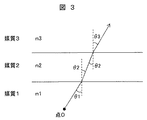
次に、フローセル中の反応液から光学窓を通して光伝送光学系へ伝播する光の光路について検討する。図3のように媒質1(屈折率n1)の任意の点(点0)を起点として発光し、媒質2(屈折率n2)を透過し、媒質3(屈折率n3)へ出射する光線を考える場合、スネルの法則により、以下の式が成立する。(ただし、説明を簡略化するため光線を二次元平面内で考えることとし、内角度θ1、θ2、θ3は、媒質境界面の法線に対する光線の入射角とする。)
n1*sinθ1 = n2*sinθ2 ・・・(1)
n2*sinθ2 = n3*sinθ3 ・・・(2)
ここで、発光側が空気で、光学窓がガラス、光伝送光学系が空気である場合には、点Oから光学窓へ角θ1=30°で入射する光線を考えるとθ2、θ3は表1で示す角度となる。
Next, the optical path of light propagating from the reaction solution in the flow cell to the optical transmission optical system through the optical window will be examined. As shown in FIG. 3, consider a light beam that emits light from an arbitrary point (point 0) of the medium 1 (refractive index n1), passes through the medium 2 (refractive index n2), and is emitted to the medium 3 (refractive index n3). In this case, the following formula is established according to Snell's law. (However, in order to simplify the explanation, the light beam is considered in a two-dimensional plane, and the internal angles θ1, θ2, and θ3 are incident angles of the light beam with respect to the normal line of the medium boundary surface.)
n1 * sin θ1 = n2 * sin θ2 (1)
n2 * sin θ2 = n3 * sin θ3 (2)
Here, when the light emission side is air, the optical window is glass, and the optical transmission optical system is air, θ2 and θ3 are given in Table 1 when light rays incident from the point O to the optical window at an angle θ1 = 30 ° are considered. It becomes the angle shown.

しかし、本実施例におけるフローセル中には反応液が導入されており、発光側の媒質1は水に相当する屈折率1.3となることから、θ2、θ3は表2で示す角度となる。 However, since the reaction liquid is introduced into the flow cell in the present embodiment and the medium 1 on the light emission side has a refractive index of 1.3 corresponding to water, θ2 and θ3 are angles shown in Table 2.
これらの関係を図4に示す。直線aは発光側が空気の場合の光路、直線bが本実施例における反応液の場合の光路を示す。図示するように、ある点からの光線が同方向へ広がった場合、発光側が反応液であるフローセルでは、発光側が気体である場合と比較して光が中心軸から外部へ広がりやすく、散逸しやすい状態になることがわかる。そこで本実施例では、図1に示すように、光伝送光学系110の入射口122を光学窓102に接触させることで、反応液からの光を散逸することなく伝送するようにしている。
These relationships are shown in FIG. A straight line a indicates an optical path when the light emission side is air, and a straight line b indicates an optical path when the reaction liquid in this embodiment is used. As shown in the figure, when a light beam from a certain point spreads in the same direction, in the flow cell in which the light emission side is a reaction liquid, the light is likely to spread from the central axis to the outside as compared with the case where the light emission side is a gas, and is easily dissipated. It turns out that it will be in a state. Therefore, in this embodiment, as shown in FIG. 1, the
他方、ホトマル111の受光部は、光伝送光学系110の出射口123より大きくし、低角で出射される光線をも受光できるようにすることで、光を散逸を防いでいる。例えば光伝送光学系110の形状が、外部直径約14mm、内部直径約13mmの中空円筒形状である場合、ホトマルの感受面は直径20mm程度とする。ミラー基材119は、ガラス、金属、アクリル、樹脂等の反射面120をなめらかでかつ安定に保持できるものであればどのようなものでもよい。また、反射面120は、AlやAuなどの金属イオンのスパッタ、メッキ(反射率、約85%程度)や、反射フィルム(数百ミクロン程度、反射率95%以上)等の高反射率の反射材によって製作することが可能である。
On the other hand, the light receiving portion of the
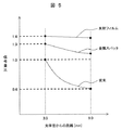
図5は本実施例による信号量の変化を示す図であり、光学窓102からホトマル111までの距離3.0mmを基準(信号量比1)に、ホトマル111を光学窓102から遠ざけた場合の信号量の変化を示す。本実施例では、光伝送光学系の入射口122を光学窓102に接触させているので、距離3.0mmまでにおける光の散逸がなく、更にホトマル111を遠ざけた場合も、反射フィルム又は金属スパッタで形成した反射面の作用で、従来は信号量が40%に減少するのに対して、本実施例によれば信号量の増加が可能である。
FIG. 5 is a diagram showing changes in the signal amount according to the present embodiment, in the case where the distance from the
図6に光伝送光学系110の内面120を金属イオンスパッタとし、ホトマル111の位置を9.0mmとした時、フローセル101の測光部104の制御温度とホトマル111の感光面121の温度との関係を示す。従来はフローセルの制御温度に伴ってホトマルの温度上昇が確認されていたが、本実施例によればホトマル温度がほとんど変化しなかった。したがって本実施例によれば、ホトマル111と光学窓102との断熱効果が高まり、温度に由来するホトマル111のノイズ上昇や変動を抑えることが可能である。
FIG. 6 shows the relationship between the control temperature of the
図7は本発明の第2の実施例を示す。フローセル201は、流路203と光学窓202とからなる。流路203へ容器208内の発光体を含む反応液209を、流体制御部218により制御されたポンプ207により供給口205から吸引し、流路203の一部を成している測光部204へ導入する。光学窓202は、石英ガラスや透明樹脂等、蛍光体212の発光波長が透過する性質で厚みは約2mm〜5mm程度であり流路203の内圧に耐えられる強度があればどのようなものでもよい。温度制御部217により測光部204にて反応液が一定温度となるようヒーター214で制御される。ヒーター214は、ペルチェ素子のような発熱・吸熱が可能な素子であればどのようなものでも代わりとして使用可能である。
FIG. 7 shows a second embodiment of the present invention. The
反応液の発光は試薬を混合することで開始されてもよいし、電圧の印加等で開始するようにしてもよく、いずれにせよ発光開始から発光終了時までの間に測光部204で目的物質濃度に比例して蛍光が放射されるよう流体制御部218により流路203を介して測光部へ導入される。反応液中、蛍光体212から放射された光線213は、流路203、光学窓202を透過し、光伝送光学系210によりその表面で反射され、ホトマル211に伝播され、ホトマルの感光面221にて光が電気信号に変換される。ホトマル211は、光を電子に変換し増倍させる光検出器であるが、多くは円柱構造をしており長細い形状をしている。そのためフローセルと垂直方向へホトマル211が張り出す格好となる。そこで、光伝送光学系210の中心軸を曲線状とし、入射口と出射口の中心軸を異なる方向に向けて配置することによって、システム全体のコンパクト化が実現可能となる。互いの軸のずれ角については90度以内が好ましい。
Luminescence of the reaction solution may be started by mixing reagents, or may be started by applying a voltage or the like. In any case, the target substance is detected by the
図8に本実施例2における光伝送光学系210の断面図を示す。光伝送光学系210は中空形状であり、内面220は反射面となっており、入射口222から入射した光線213を反射し、反対側の出射口223から光線213を出射する。説明のため反射面を内面220としたが、光伝送光学系210の外面側でもよい。出射された光線213を対向したホトマル211により受光する。
FIG. 8 is a sectional view of the optical transmission
実施例1と同様に、光学窓202と入射口222とは接触して配置することで光の散逸を防ぎ、ホトマル211の受光部は出射口223より大きくして低角で出射される光線をも受光するように構成する。
Similar to the first embodiment, the
ミラー基材219は、ガラス、金属、アクリル、樹脂等の反射面220をなめらかでかつ安定に保持できるものであればどのようなものでもよい。また、反射面220は、AlやAuなどの金属イオンのスパッタ、メッキ(反射率、約85%程度)や、反射フィルム(数百ミクロン程度、反射率95%以上)等の高反射率の反射材によって製作することが可能である。反射フィルムにより曲面形成が困難な場合は、光伝送光学系210は屈折部ごとに複数部品に分けて製作してもよい。
The
このように本実施例によれば、光伝送光学系210の中心軸224を曲線状にすることができるので、自動分析装置のシステム構成に合わせてコンパクト化することができ、この場合も高感度化、高安定化を損なうことなく、微量な反応液に対しても高S/Nの分析を行うことができる。
As described above, according to this embodiment, the
101、201・・・フローセル
102、202・・・光学窓
103、203・・・流路
104、204・・・測光部
105、205・・・供給口
106、206・・・排出口
107、207・・・ポンプ
108、208・・・容器
109、209・・・反応液
110、210・・・光伝送光学系
111、211・・・ホトマル
112、212・・蛍光体
113、213・・・光線
114、214・・・ヒーター
119、219・・・ミラー基材
120、220・・・反射面(内面)
122、222・・・入射口
123、223・・・出射口
124、224・・・光伝送光学系の中心軸
101, 201 ... flow
122, 222...
Claims (5)
流路温度を制御する温度制御部と、
前記反応液中に広がる発光物質からの光を通過させる光学窓と、
前記光学窓を通過した光を検知する光電子増倍管とを備え、
前記光電子増倍管からのデータを処理して前記反応液に含まれる発光物質の量を分析する自動分析装置において、
前記光学窓に対面する入射口と、
前記光電子増倍管の受光面と対面する出射口と、
一端に前記入射口を有し他端に前記出射口を有する中空部と、
前記入射口から入射した前記発光物質からの光を前記中空部の反射材により覆われた内面において反射させて前記出射口へ伝播する反射面とからなる光伝送光学系を設け、
前記光伝送光学系の入射口は、前記光学窓の上面に接触して配置され、
前記光電子増倍管の受光面の大きさは対面する前記出射口の大きさより大きくすることを特徴とする自動分析装置。 A flow path for flowing a reaction solution containing a luminescent substance;
A temperature control unit for controlling the flow path temperature;
An optical window that allows light from a luminescent material that spreads in the reaction solution to pass through ;
Before SL and a photomultiplier tube for detecting the light passing through the optical window,
In an automatic analyzer that processes the data from the photomultiplier tube and analyzes the amount of the luminescent substance contained in the reaction solution,
An entrance facing the optical window;
An exit opening facing the light receiving surface of the photomultiplier;
A hollow portion having the entrance at one end and the exit at the other end ;
The light from the light-emitting substance that has entered from the entering morphism port is provided an optical transmission optical system comprising a reflecting surface which propagates to said exit by reflecting on the inner surface covered with anti Ysaÿe of the hollow portion,
The entrance of the optical transmission optical system is disposed in contact with the upper surface of the optical window,
The automatic analyzer is characterized in that the size of the light receiving surface of the photomultiplier tube is larger than the size of the exit port facing the photomultiplier tube.
前記流路の一部が、前記流路に導入された反応液中に含まれる発光物質に発光を開始させるための測光部をなし、
前記光学窓は、前記測光部と前記光伝送光学系の間に設けられており、
前記光伝送光学系の入射口の大きさは、前記測光部よりも大きいことを特徴とする自動分析装置。 The automatic analyzer according to claim 1, wherein
A part of the flow path constitutes a photometric part for starting light emission of the luminescent substance contained in the reaction solution introduced into the flow path,
The optical window is provided between the photometry unit and the optical transmission optical system,
The automatic analyzer is characterized in that the size of the entrance of the optical transmission optical system is larger than that of the photometry unit.
前記光伝送光学系の出射口は、前記光電子増倍管の受光面と離間して配置されていることを特徴とする自動分析装置。 The automatic analyzer according to claim 1, wherein
The automatic analyzer according to claim 1, wherein an emission port of the optical transmission optical system is disposed apart from a light receiving surface of the photomultiplier tube.
前記光伝送光学系は、円筒形状をなす前記中空部と、その内面に形成された前記反射面とよりなり、
前記中空部と、前記入射口と、前記出射口とが、同一軸線上に配置されていることを特徴とする自動分析装置。 The automatic analyzer according to claim 1, wherein
The optical transmission optical system is composed of the hollow portion having a cylindrical shape and the reflection surface formed on the inner surface thereof.
The automatic analyzer according to claim 1, wherein the hollow portion, the entrance, and the exit are arranged on the same axis.
前記光伝送光学系は、円筒形状をなす前記中空部と、その内面に形成された前記反射面とよりなり、
前記中空部が曲線状をなして前記入射口と出射口の中心軸を異なる方向に向けて配置してなることを特徴とする自動分析装置。 The automatic analyzer according to claim 1, wherein
The optical transmission optical system is composed of the hollow portion having a cylindrical shape and the reflection surface formed on the inner surface thereof.
An automatic analyzer characterized in that the hollow portion has a curved shape and is arranged with the central axes of the entrance and the exit facing in different directions.
Priority Applications (1)
| Application Number | Priority Date | Filing Date | Title |
|---|---|---|---|
| JP2014081060A JP5805259B2 (en) | 2014-04-10 | 2014-04-10 | Automatic analyzer |
Applications Claiming Priority (1)
| Application Number | Priority Date | Filing Date | Title |
|---|---|---|---|
| JP2014081060A JP5805259B2 (en) | 2014-04-10 | 2014-04-10 | Automatic analyzer |
Related Parent Applications (1)
| Application Number | Title | Priority Date | Filing Date |
|---|---|---|---|
| JP2010101799A Division JP5524698B2 (en) | 2010-04-27 | 2010-04-27 | Automatic analyzer |
Publications (2)
| Publication Number | Publication Date |
|---|---|
| JP2014149305A true JP2014149305A (en) | 2014-08-21 |
| JP5805259B2 JP5805259B2 (en) | 2015-11-04 |
Family
ID=51572366
Family Applications (1)
| Application Number | Title | Priority Date | Filing Date |
|---|---|---|---|
| JP2014081060A Active JP5805259B2 (en) | 2014-04-10 | 2014-04-10 | Automatic analyzer |
Country Status (1)
| Country | Link |
|---|---|
| JP (1) | JP5805259B2 (en) |
Cited By (2)
| Publication number | Priority date | Publication date | Assignee | Title |
|---|---|---|---|---|
| JP2017138306A (en) * | 2016-01-31 | 2017-08-10 | アークレイ株式会社 | Analysis tool and analysis |
| WO2021205771A1 (en) | 2020-04-08 | 2021-10-14 | 株式会社日立ハイテク | Automatic analysis device |
Citations (2)
| Publication number | Priority date | Publication date | Assignee | Title |
|---|---|---|---|---|
| JP2003083896A (en) * | 2001-09-12 | 2003-03-19 | Kometto:Kk | Method and device for analysis using chemiluminescence |
| JP2004205415A (en) * | 2002-12-26 | 2004-07-22 | Mitsubishi Electric Corp | Photometric analysis measuring probe apparatus, solution concentration monitoring method and spectroscopic analysis apparatus |
-
2014
- 2014-04-10 JP JP2014081060A patent/JP5805259B2/en active Active
Patent Citations (2)
| Publication number | Priority date | Publication date | Assignee | Title |
|---|---|---|---|---|
| JP2003083896A (en) * | 2001-09-12 | 2003-03-19 | Kometto:Kk | Method and device for analysis using chemiluminescence |
| JP2004205415A (en) * | 2002-12-26 | 2004-07-22 | Mitsubishi Electric Corp | Photometric analysis measuring probe apparatus, solution concentration monitoring method and spectroscopic analysis apparatus |
Non-Patent Citations (2)
| Title |
|---|
| JPN6015003116; TERRY,J.M. 他: '"Chemiluminescence Detector with a Serpentine Flow Cell"' ANALYTICAL CHEMISTRY Volume 80, Number 24, 20081117, Pages 9817-9821 * |
| JPN6015003117; AMIRAV,A. 他: '"Pulsed Flame Photometer Detector for Gas Cheromatography"' ANALYTICAL CHEMISTRY Volume 67, Number 18, 19950915, Pages 3305-3318 * |
Cited By (2)
| Publication number | Priority date | Publication date | Assignee | Title |
|---|---|---|---|---|
| JP2017138306A (en) * | 2016-01-31 | 2017-08-10 | アークレイ株式会社 | Analysis tool and analysis |
| WO2021205771A1 (en) | 2020-04-08 | 2021-10-14 | 株式会社日立ハイテク | Automatic analysis device |
Also Published As
| Publication number | Publication date |
|---|---|
| JP5805259B2 (en) | 2015-11-04 |
Similar Documents
| Publication | Publication Date | Title |
|---|---|---|
| US10126229B2 (en) | Optical measurement device | |
| US20200003688A1 (en) | Surface Plasmon Resonance Fluorescence Analysis Device And Surface Plasmon Resonance Fluorescence Analysis Method | |
| JP6587024B2 (en) | Detection method and detection apparatus | |
| JP5524698B2 (en) | Automatic analyzer | |
| JP5805259B2 (en) | Automatic analyzer | |
| EP3159677B1 (en) | Detection device | |
| JP2014032148A (en) | Surface plasmon excitation enhanced fluorescence acquisition structure and surface plasmon excitation enhanced fluorescence measurement system | |
| EP3705875B1 (en) | An apparatus and method for detecting photoluminescent light emitted from a sample | |
| JPWO2018034208A1 (en) | Measuring method | |
| KR101909380B1 (en) | Fluorescence measuring apparatus and method | |
| US10775307B2 (en) | Optical fiber fluorescence detection device | |
| JP5300249B2 (en) | Liquid analyzer | |
| JP6529591B2 (en) | Detector for luminescence analysis and automatic analyzer | |
| US10267735B2 (en) | Surface plasmon-field enhanced fluorescence detection device | |
| JP2015102455A (en) | Sensor device and measurement method | |
| JP2006308412A (en) | Fluorescence resonance detector |
Legal Events
| Date | Code | Title | Description |
|---|---|---|---|
| A977 | Report on retrieval |
Free format text: JAPANESE INTERMEDIATE CODE: A971007 Effective date: 20150116 |
|
| A131 | Notification of reasons for refusal |
Free format text: JAPANESE INTERMEDIATE CODE: A131 Effective date: 20150203 |
|
| A521 | Written amendment |
Free format text: JAPANESE INTERMEDIATE CODE: A523 Effective date: 20150331 |
|
| TRDD | Decision of grant or rejection written | ||
| A01 | Written decision to grant a patent or to grant a registration (utility model) |
Free format text: JAPANESE INTERMEDIATE CODE: A01 Effective date: 20150818 |
|
| A61 | First payment of annual fees (during grant procedure) |
Free format text: JAPANESE INTERMEDIATE CODE: A61 Effective date: 20150901 |
|
| R150 | Certificate of patent or registration of utility model |
Ref document number: 5805259 Country of ref document: JP Free format text: JAPANESE INTERMEDIATE CODE: R150 |
|
| S531 | Written request for registration of change of domicile |
Free format text: JAPANESE INTERMEDIATE CODE: R313531 |
|
| S533 | Written request for registration of change of name |
Free format text: JAPANESE INTERMEDIATE CODE: R313533 |
|
| R350 | Written notification of registration of transfer |
Free format text: JAPANESE INTERMEDIATE CODE: R350 |