JP2014149208A - Leak detector and leak detection method - Google Patents
Leak detector and leak detection method Download PDFInfo
- Publication number
- JP2014149208A JP2014149208A JP2013017638A JP2013017638A JP2014149208A JP 2014149208 A JP2014149208 A JP 2014149208A JP 2013017638 A JP2013017638 A JP 2013017638A JP 2013017638 A JP2013017638 A JP 2013017638A JP 2014149208 A JP2014149208 A JP 2014149208A
- Authority
- JP
- Japan
- Prior art keywords
- sound
- leakage
- main
- acoustic
- spectrum
- Prior art date
- Legal status (The legal status is an assumption and is not a legal conclusion. Google has not performed a legal analysis and makes no representation as to the accuracy of the status listed.)
- Pending
Links
Images


Abstract
Description
本発明は、被検査物の機器から漏洩する気体を検出する漏洩検出装置及び漏洩検出方法に関する。 The present invention relates to a leak detection apparatus and a leak detection method for detecting a gas leaking from a device to be inspected.
従来、気体の漏洩試験方法として、石鹸水法やガス検知法、超音波検知法、その他の試験方法が知られている。 Conventionally, soap water method, gas detection method, ultrasonic detection method, and other test methods are known as gas leakage test methods.
石鹸水法は、被検査物の内部に空気圧を加えた後に、被検査物の外側に石鹸水を塗ることによって生ずる石鹸水の泡の膨らみを観察して、気体の漏洩を判別する方法である。石鹸水法は、液体を塗布することができない素材、高温、低温の検体には適用することができない。また、検査後に洗浄が必要になることから、洗浄を行うことかできない検体にも、適用することができない。 The soap water method is a method of determining gas leakage by observing the swelling of soap water bubbles generated by applying soap water to the outside of the inspection object after applying air pressure to the inside of the inspection object. The soapy water method cannot be applied to materials that cannot be applied with liquid, high-temperature and low-temperature specimens. In addition, since cleaning is required after the test, it cannot be applied to a specimen that cannot be cleaned.
ガス検知法の一例として、比較的重いガスを注入しておき、ガスの漏れを水銀などの触媒を用いて質量分析を行う方法が知られている。 As an example of a gas detection method, a method is known in which a relatively heavy gas is injected and mass spectrometry is performed using a catalyst such as mercury for leakage of the gas.
ガス検知法は、微小漏洩に対する検出に適するものの、計測レンジが狭いために、検体に対する適用範囲が狭いという問題がある。 Although the gas detection method is suitable for detection of minute leaks, there is a problem that the application range to the specimen is narrow because the measurement range is narrow.
超音波検知法は、気体が被検査物から漏洩する際に発生する超音波を検出する方法である。超音波検知法は、計測レンジの下限が高いことが短所となっている。 The ultrasonic detection method is a method for detecting an ultrasonic wave generated when gas leaks from an inspection object. The ultrasonic detection method has a disadvantage that the lower limit of the measurement range is high.
被検査物の周囲では、人の活動に伴って衝撃音や摩擦音に起因する超音波が発生しているために、検出すべき超音波が、これらの騒音に埋もれてしまう可能性が高い。また、超音波検知法では、流量の定量的評価を行うことができなかった。 Since an ultrasonic wave caused by an impact sound or a frictional sound is generated around the object to be inspected due to human activity, there is a high possibility that the ultrasonic wave to be detected is buried in these noises. In addition, the ultrasonic detection method cannot quantitatively evaluate the flow rate.
特許文献1には、漏洩量測定装置が開示されている。特許文献1に記載されている漏洩量測定装置は、映像観測装置と、音響計測装置と、特徴量抽出装置と、漏洩量に関するデータベースと、漏洩量検索装置とを備えている。 Patent Document 1 discloses a leakage amount measuring apparatus. The leakage amount measuring device described in Patent Literature 1 includes a video observation device, an acoustic measurement device, a feature amount extraction device, a database regarding leakage amount, and a leakage amount search device.
特許文献1に記載されている前記映像観測装置は、漏洩流体の映像を観測する。前記音響計測装置は、漏洩流体の音響を計測する。前記特徴量抽出装置は、映像観測装置および音響計測装置の出力から漏洩流体の特徴量を抽出する。前記漏洩量検索装置は、抽出された一つ又は複数の特徴量によって、流体圧力および温度、漏洩媒体の相状態、漏洩部の面積および形状毎に作成した逐次の漏洩量に関するデータベースを検索して漏洩量を求める。更に前記漏洩量検索装置は、漏洩流体の漏洩量と漏洩時間とから漏洩事象による全漏洩量を求め、逐次の漏洩量、漏洩事象による全漏洩量、漏洩部の面積および形状をモニタ表示可能に構成している。 The image observation apparatus described in Patent Document 1 observes an image of a leaking fluid. The acoustic measuring device measures the sound of the leaked fluid. The feature quantity extraction device extracts a feature quantity of the leaked fluid from outputs of the video observation device and the acoustic measurement device. The leak amount search device searches a database regarding sequential leak amounts created for each fluid pressure and temperature, the phase state of the leak medium, the area and shape of the leak portion based on the one or more extracted feature amounts. Obtain the amount of leakage. Furthermore, the leak amount search device can obtain the total leak amount due to the leak event from the leak amount and leak time of the leaked fluid, and can monitor and display the sequential leak amount, the total leak amount due to the leak event, and the area and shape of the leak portion. It is composed.
本発明の目的は、組み立てた状態の被検査物の外部から気体の漏洩を検出することが可能な漏洩検出装置、及び漏洩検出方法を提供することである。 An object of the present invention is to provide a leak detection device and a leak detection method capable of detecting a gas leak from the outside of an inspected object in an assembled state.
以下に、(発明を実施するための形態)で使用される番号を用いて、課題を解決するための手段を説明する。これらの番号は、(特許請求の範囲)の記載と(発明を実施するための形態)との対応関係を明らかにするために付加されたものである。ただし、それらの番号を、(特許請求の範囲)に記載されている発明の技術的範囲の解釈に用いてはならない。 The means for solving the problem will be described below using the numbers used in the (DETAILED DESCRIPTION). These numbers are added to clarify the correspondence between the description of (Claims) and (Mode for Carrying Out the Invention). However, these numbers should not be used to interpret the technical scope of the invention described in (Claims).
本発明による漏洩検出装置は、主音響検出器(12m)と、周波数分析部(24)と、漏洩音抽出部(28)と、漏洩量算出部(32)を備える。前記主音響検出器(12m)は、被検査物における漏洩部(8)から漏洩する気体の超音波漏洩音(Ls)、及び前記漏洩部(8)の方向から伝播する周囲の騒音を検出して主音波信号(Sm)を出力する。前記周波数分析部(24)は、前記主音波信号(Sm)に対して周波数分析を行って、主音響スペクトラム(Fm)を出力する。前記漏洩音抽出部(28)は、前記主音響スペクトラム(Fm)に含まれる周囲の騒音成分を減少させて前記超音波漏洩音(Ls)を抽出して、計測音圧(SPL)を取得する。前記漏洩量算出部(32)は、前記主音響検出器(12m)から前記漏洩部(8)近傍までの検体距離(r)を取得して、当該検体距離(r)及び前記計測音圧(SPL)を用いて、前記超音波漏洩音(Ls)の発生音圧を算出する。 The leak detection apparatus according to the present invention includes a main sound detector (12m), a frequency analysis unit (24), a leak sound extraction unit (28), and a leak amount calculation unit (32). The main acoustic detector (12m) detects ultrasonic leak sound (Ls) of gas leaking from the leaking part (8) in the inspection object and ambient noise propagating from the direction of the leaking part (8). To output a main sound wave signal (Sm). The frequency analysis unit (24) performs frequency analysis on the main acoustic wave signal (Sm) and outputs a main acoustic spectrum (Fm). The leaky sound extraction unit (28) extracts the ultrasonic leaky sound (Ls) by reducing ambient noise components included in the main acoustic spectrum (Fm), and acquires a measured sound pressure (SPL). . The leakage amount calculation unit (32) acquires a specimen distance (r) from the main acoustic detector (12m) to the vicinity of the leakage part (8), and the specimen distance (r) and the measured sound pressure ( SPL) is used to calculate the generated sound pressure of the ultrasonic leakage sound (Ls).
前記漏洩量算出部(32)は、漏洩する気体の密度及び気体の音速を含む検出環境に応じて決定される環境定数(b)を取得する。更に前記漏洩量算出部(32)は、前記発生音圧(PWL)及び環境定数(b)に基づいて、漏洩部における気体の漏洩量(F)を算出する。 The leakage amount calculation unit (32) acquires an environmental constant (b) determined according to a detection environment including the density of the leaking gas and the sound velocity of the gas. Further, the leakage amount calculation unit (32) calculates a gas leakage amount (F) in the leakage portion based on the generated sound pressure (PWL) and the environmental constant (b).
本発明による漏洩検出装置は、上記構成に加えて、漏洩する気体の密度及び気体の音速を含む検出環境に応じて決定される環境定数(b)を記録するデータベース(36)を備える。前記漏洩量算出部(32)は、前記データベース(36)から環境定数(b)を取得して、漏洩部における気体の漏洩量(F)を算出する。 In addition to the above-described configuration, the leak detection apparatus according to the present invention includes a database (36) that records an environmental constant (b) determined according to a detection environment including the density of leaking gas and the sound velocity of the gas. The leakage amount calculation unit (32) acquires the environmental constant (b) from the database (36), and calculates a gas leakage amount (F) in the leakage portion.
また、本発明による漏洩検出装置は、前記漏洩部(8)と主音響検出器(12m)とを結ぶ直線と平行、且つ主音響検出器(12m)の近傍に配置され、前記主音響検出器(12m)に到達する周囲の騒音を遮る音響シールド(16)を備える。 Moreover, the leak detection apparatus according to the present invention is arranged in parallel to a straight line connecting the leak portion (8) and the main sound detector (12m) and in the vicinity of the main sound detector (12m). An acoustic shield (16) for blocking ambient noise reaching (12m) is provided.
前記音響シールド(16)は、鋼板や銅板、アルミニウム板等の金属板又は樹脂板から構成される基材(14)を含み、前記基材(14)における前記主音響検出器(12m)側の表面に、樹脂、スポンジ等の吸音材(15)を配置する。 The acoustic shield (16) includes a base material (14) made of a metal plate such as a steel plate, a copper plate, or an aluminum plate, or a resin plate, and the main acoustic detector (12m) side of the base material (14) A sound absorbing material (15) such as resin or sponge is disposed on the surface.
前記漏洩音抽出部(28)は、40kHz〜150kHzの間の超音波漏洩音(Ls)を抽出する。 The leakage sound extraction unit (28) extracts an ultrasonic leakage sound (Ls) between 40 kHz and 150 kHz.
前記主音響検出器(12m)から前記漏洩部(8)近傍までの前記検体距離(r)に関する信号を検出して出力する測距センサ(18)と、前記測距センサ(18)から取得した前記検体距離(r)に関する信号に基づいて、前記検体距離(r)を算出して出力する距離算出部(26)とを備え、前記漏洩量算出部(32)は、前記距離算出部(26)にて算出した前記検体距離(r)を取得する。 A distance measuring sensor (18) that detects and outputs a signal related to the specimen distance (r) from the main acoustic detector (12m) to the vicinity of the leaking part (8), and obtained from the distance measuring sensor (18). A distance calculation unit (26) that calculates and outputs the sample distance (r) based on a signal related to the sample distance (r), and the leakage amount calculation unit (32) includes the distance calculation unit (26). ) To obtain the specimen distance (r) calculated.
また、前記主音響検出器(12m)の近傍に配置され、前記漏洩部(8)の方向から伝播する周囲の騒音を検出して副音波信号(Ss)を出力する副音響検出器(12s)を備え、前記音響シールド(16)は、少なくとも前記主音響検出器(12m)と前記副音響検出器(12s)との間に配置され、前記副音響検出器(12s)に対する前記超音波漏洩音(Ls)の到達を遮る。前記周波数分析部(24)は、前記主音波信号(Sm)及び前記副音波信号(Ss)に対して周波数分析を行って、主音響スペクトラム(Fm)及び副音響スペクトラム(Fs)を出力する。前記漏洩音抽出部(28)は、前記主音響スペクトラム(Fm)及び前記副音響スペクトラム(Fs)を用いて、前記主音響スペクトラム(Fm)に含まれる周囲の騒音成分を減少させて前記超音波漏洩音(Ls)を抽出して、計測音圧(SPL)を取得する。 Also, a sub-acoustic detector (12s) that is disposed in the vicinity of the main acoustic detector (12m), detects ambient noise propagating from the direction of the leakage portion (8), and outputs a sub-sonic signal (Ss). The acoustic shield (16) is disposed between at least the main acoustic detector (12m) and the sub acoustic detector (12s), and the ultrasonic leak sound with respect to the sub acoustic detector (12s). The arrival of (Ls) is blocked. The frequency analysis unit (24) performs frequency analysis on the main sound signal (Sm) and the sub sound signal (Ss), and outputs a main sound spectrum (Fm) and a sub sound spectrum (Fs). The leakage sound extraction unit (28) uses the main acoustic spectrum (Fm) and the sub-acoustic spectrum (Fs) to reduce ambient noise components included in the main acoustic spectrum (Fm), thereby reducing the ultrasonic wave. The leaked sound (Ls) is extracted to obtain the measured sound pressure (SPL).
本発明によれば、組み立てた状態の被検査物の外部から気体の漏洩を検出することができる。また、気体の漏洩量を検出することが可能となる。 According to the present invention, it is possible to detect gas leakage from the outside of the inspection object in an assembled state. In addition, the amount of gas leakage can be detected.
添付図面を参照して、本発明による漏洩検出装置及び漏洩検出方法を実施するための形態を、以下に説明する。 With reference to the attached drawings, a mode for carrying out a leak detection apparatus and leak detection method according to the present invention will be described below.
(第1の実施形態)
図1を参照して、被検査物6における漏洩部8から気体の漏洩を検出する漏洩検出装置について説明する。本発明では、被検査物6の内部に予め高圧の気体を封入しておき、主音響検出器12mを用いて漏洩部8を検出すると共に、漏洩量Fを算出する。なお、検査用の気体として、例えばヘリウムガス等の気体を用いることができる。
(First embodiment)
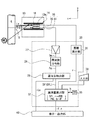
With reference to FIG. 1, the leak detection apparatus which detects the leak of gas from the
本発明に係る漏洩検出装置は、音響検出部10と、処理部20と、表示・出力部60とを備えている。音響検出部10は、漏洩部8から発せられる超音波漏洩音Ls及び漏洩部8の方向から伝播する周囲の騒音を検出して主音波信号Smを出力する。処理部20は、音響検出部10から取得した主音波信号Smに対して周波数分析を行って、気体の漏洩の有無や、漏洩している気体の流量を表す漏洩量Fを算出する。表示・出力部60は、気体の漏洩の有無(漏洩検出判定Le)や漏洩量F、漏洩部8から音響検出部10までの検体距離r、その他の情報を表示する。
The leak detection apparatus according to the present invention includes an
図1に示す音響検出部10は、主音響検出器12mと、音響シールド16と、測距センサ18とを備えている。主音響検出器12mは、漏洩部8から発せられる超音波漏洩音Ls及び漏洩部8の方向から伝播する周囲の騒音を検出して、主音波信号Smに変換して出力する。
The
音響シールド16は、漏洩部8と主音響検出器12mとを結ぶ直線と平行、且つ主音響検出器12mの近傍に配置される。音響シールド16は、周囲の騒音源から主音響検出器12mに到達する超音波の騒音を遮るものである。測距センサ18は、主音響検出器12mから、被検査物6における漏洩部8近傍までの検体距離rに関する信号を検出して出力する。主音響検出器12mとして、例えば指向性を有する超音波マイクロフォンを用いることができる。
The
被検査物6の漏洩部8から発せられる超音波漏洩音Lsの主な周波数帯は、40〜150kHzの超音波である。従って、超音波漏洩音Lsの波長は8.25〜2.2mm程度となるために、音響シールド16端部における回折は生じにくい。従って、音響シールド16を配置することによって、漏洩部8以外から発せられている超音波の騒音に対する遮音を効果的に行うことができる。これにより、漏洩部8の検出や漏洩量Fの算出精度を向上させることができる。なお、主音響検出器12mによる超音波検出の指向性が強い場合には、音響シールド16の配置を省略することができる。
The main frequency band of the ultrasonic leakage sound Ls emitted from the
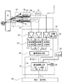
次に、図2を参照して、音響検出部10及び処理部20の構成とその機能について説明する。図2に示す音響検出部10の中央部には、漏洩部8の方向から伝播する音波を取得する主音響検出器12mが配置されている。主音響検出器12mの音響検出方向は、漏洩部8の方向が最大利得となるように走査して、検出方向を決定する。図2に示す例では、漏洩部8と主音響検出器12mとを結ぶ直線の方向をX方向と定義し、X方向に対して直角な方向をY方向と定義する。
Next, the configurations and functions of the
主音響検出器12mの近傍の両脇(図2に示す+Y方向及び−Y方向)には、板状の音響シールド16がそれぞれX方向と平行に配置されている。音響シールド16の基材14は、漏洩部8から発せられる超音波漏洩音Lsを反射せずに吸収する素材を含むことが好ましい。この素材として、鋼板や銅板、アルミニウム板等の金属板や、樹脂板を用いることができる。図2に示す実施形態では、更に吸音性や制振性を向上させるために、音響検出器側の表面に、樹脂、スポンジ等の吸音材15を配置して、主音響検出器12mに対する超音波の反射を低減させている。
On both sides in the vicinity of the main
図2に示すように、被検査物6の漏洩部8から発せられた超音波漏洩音Lsの一部は−X方向に伝播してゆき、主音響検出器12mに到達して主音波信号Smに変換される。しかし、漏洩部8の周囲に存在している騒音源NEから放射される騒音は、音響シールド16に遮音されて主音響検出器12mには直接到達することができない。
As shown in FIG. 2, a part of the ultrasonic leakage sound Ls emitted from the
音響検出部10に配置されている測距センサ18は、漏洩部8から主音響検出器12mまでの検体距離rを精度良く測定するために、主音響検出器12mの近傍に配置することが好ましい。測距センサ18として、超音波測距センサ、三角測量式光センサ、光波測距儀、電波測距儀、静電容量センサ、その他のセンサを用いることができる。
The
図2に示す処理部20は、増幅器22と、周波数分析部24と、距離算出部26と、漏洩音抽出部28と、漏洩量算出部32と、データベース36とを備えている。増幅器22は、主音響検出器12mから取得した音波信号に対して増幅やフィルタリング等の信号処理を行って、処理後の主音波信号Smを出力する。
The
周波数分析部24は、主音波信号Smに対して周波数分析を行って、周波数帯域Sf毎の主音響スペクトラムFm(計測音圧の一形態)を出力する。主音響スペクトラムFmは、周波数帯域Sf毎のパワースペクトラム又はリニアスペクトラムであり、FFT演算(高速フーリエ演算)やフィルタリングの手法を用いて取得することができる。FFTの時間窓として、ハニング、矩形等を用いることができ、サンプリング時間を長く設定することによって、単発的な騒音の影響を減少させることができる。
The
図2に示す距離算出部26は、測距センサ18から取得した信号に基づいて、主音響検出器12mから漏洩部8近傍までの検体距離rを算出して出力する。また、検体距離rに関する情報は、利用者が入力部38を操作して入力することもできる。
The
漏洩音抽出部28は、主音響スペクトラムFmを入力して、それぞれの周波数帯域Sf毎の音響スペクトラムSpに対してゲインを設定して、主音響スペクトラムFmに含まれる周囲の騒音成分を減少させて、超音波漏洩音Lsを抽出する処理を行う。
The leaky
漏洩音抽出部28における超音波漏洩音Lsの抽出処理の一例を、図3を用いて説明する。図3に示すように、漏洩音抽出部28では、周波数分析部24から主音響スペクトラムFmを取得している。なお、同図に示す周波数帯域Sfは、それぞれの音響スペクトラムSpの周波数fの分解能に相当する。また、同図に示す漏洩音域Bfは、40〜150kHzの範囲内におけるいずれかの音域である。
An example of the extraction process of the ultrasonic leakage sound Ls in the leakage
主音響スペクトラムFmには、漏洩部8の方向から伝播する周囲の雑音と、超音波漏洩音Lsとが含まれている。被検査物6おける気体の漏洩を検出する際には、先ず利用者が漏洩部8の存在を知る必要がある。従って漏洩音抽出部28は、超音波漏洩音Lsの存在を通知するための漏洩検出判定Leを検出する機能を有している。漏洩検出判定Leは、主音響スペクトラムFmの漏洩音域Bfにおいて、例えば音響スペクトラムSpの値が、所定の漏洩音閾値Psを超えているか否かに基づいて判断することができる。
The main acoustic spectrum Fm includes ambient noise propagating from the direction of the
図3に示す実施形態では、漏洩音閾値Psを超えている部分が存在しているので、漏洩音抽出部28は漏洩検出判定Leの出力を決定する。この漏洩検出判定Leは、表示・出力部60に伝達されて、利用者に通知される。
In the embodiment shown in FIG. 3, there is a portion that exceeds the leakage sound threshold value Ps, so the leakage
なお、漏洩音閾値Psは、主音響検出器12mから被検査物6における漏洩部8までの検体距離rに応じて変更することもできる。
The leakage sound threshold value Ps can also be changed according to the specimen distance r from the main
超音波漏洩音Lsは超音波であるため、利用者が聞くことはできない。よって、超音波漏洩音Lsが放射されていたとしても、利用者は漏洩部8の存在や漏洩部8の場所を特定することができない。従って、利用者が漏洩部8の存在を探す際には、例えば音響検出部10を伏角・方位角方向に走査しながら、漏洩検出判定Leの存在を調査することによって行う。利用者が漏洩検出判定Leの存在を確認した場合には、音響検出部10を漏洩部8に接近させて、漏洩部8の正確な位置や漏洩量を測定することができる。
Since the ultrasonic leakage sound Ls is an ultrasonic wave, the user cannot hear it. Therefore, even if the ultrasonic leak sound Ls is radiated, the user cannot specify the presence of the leaking
また、図3に示すように、漏洩音抽出部28は、主音響スペクトラムFmに含まれる漏洩音域Bfの音域の超音波漏洩音Lsを抽出して、主音響スペクトラムFmに含まれる周囲の騒音成分を減少させて漏洩音響スペクトラムDfを生成する機能を備えている。また、漏洩音抽出部28は、漏洩音響スペクトラムDfの漏洩音域Bfにおける音響スペクトラムSpの総和(面積に相当する)、又は音響スペクトラムSpの最大値等に基づいて演算を行って計測音圧SPL(dB)を取得して、漏洩量算出部32に出力することができる。
As shown in FIG. 3, the leaking
図2に示す漏洩量算出部32は、漏洩音抽出部28から入力した計測音圧SPLと、距離算出部26等から入力した検体距離rとを用いて、漏洩量Fを算出する処理を行う。以下、漏洩量Fの算出方法について、数式を用いて説明する。
The leakage
(計測音圧SPLと発生音圧PWLとの関係)
気体の漏洩部8における超音波漏洩音の発生音圧PWL(dB)は、漏洩音抽出部28から入力した超音波漏洩音の計測音圧SPL(dB)と、距離算出部26等から入力した検体距離r(m)と、下記の(式1)とを用いて算出することができる。
PWL=SPL+10・log(2×π×r2)−10・log(S) …(式1)
但し、
PWL:漏洩部における超音波漏洩音の発生音圧(dB)
SPL:主音響検出器による超音波漏洩音の計測音圧(dB)
r:主音響検出器から漏洩部までの検体距離(m)
S:主音響検出器及び副音響検出器における有感部面積(m2)
(Relationship between measured sound pressure SPL and generated sound pressure PWL)
The generated sound pressure PWL (dB) of the ultrasonic leakage sound in the
PWL = SPL + 10 · log (2 × π × r 2 ) −10 · log (S) (Formula 1)
However,
PWL: Generated sound pressure (dB) of ultrasonic leakage sound at the leaking part
SPL: Measurement sound pressure (dB) of ultrasonic leak sound by main acoustic detector
r: Specimen distance from main acoustic detector to leaking part (m)
S: Sensitive area (m 2 ) in the main acoustic detector and the secondary acoustic detector
(発生音圧PWLの計算式)
一方、気体の漏洩部8における超音波漏洩音の発生音圧PWLは、下記の(式2)を用いて算出することができる。
PWL=10・logρ+20・logd+80・logV−50・logC+74 …(式2)
但し、
PWL:漏洩部における超音波漏洩音の発生音圧(dB)
ρ:噴出気体密度(Kg/m2)
d:漏洩部直径(m)
V:漏洩部における気体の噴出速度(m/s)
C:大気圧中における音速(m/s)
(Calculation formula of generated sound pressure PWL)
On the other hand, the generated sound pressure PWL of the ultrasonic leakage sound in the
PWL = 10 · log ρ + 20 · logd + 80 · log V−50 · log C + 74 (Formula 2)
However,
PWL: Generated sound pressure (dB) of ultrasonic leakage sound at the leaking part
ρ: ejection gas density (Kg / m 2 )
d: Diameter of leaking part (m)
V: Gas ejection speed (m / s) at the leaking part
C: Sound velocity in atmospheric pressure (m / s)
(漏洩部における気体の漏洩量Fの計算式)
漏洩部8における気体の漏洩量Fは、下記の(式3)を用いて算出することができる。
F=V×π×d2 …(式3)
但し、
F:漏洩部における気体の漏洩量(m3/s)
V:漏洩部における気体の噴出速度(m/s)
d:漏洩部直径(m)
(Calculation formula for the amount of gas leakage F at the leakage part)
The gas leakage amount F in the
F = V × π × d 2 (Formula 3)
However,
F: Gas leakage amount (m 3 / s) in the leakage part
V: Gas ejection speed (m / s) at the leaking part
d: Diameter of leaking part (m)
(計算式の変形と発生音圧PWLの算出)
上記(式2)に(式3)を代入すると、発生音圧PWLを算出することができる。先ず、上記(式3)は、以下のように変形することができる。
logF=log(V×π×d2)
=logV+logπ+2・logd …(式4)
上記(式4)をlogdについて解くと、下記の(式5)が得られる。
2・logd=logF−logV−logπ …(式5)
(Modification of calculation formula and calculation of generated sound pressure PWL)
By substituting (Equation 3) into (Equation 2), the generated sound pressure PWL can be calculated. First, the above (formula 3) can be modified as follows.
log F = log (V × π × d 2 )
= LogV + logπ + 2 · logd (Formula 4)
When the above (formula 4) is solved for logd, the following (formula 5) is obtained.
2 · logd = logF−logV−logπ (Formula 5)
ここで、上記(式2)に(式5)を代入すると、下記の(式6)が得られる。
PWL=10・logρ+10・logF−10・logV−10・logπ+80・logV−50・logC+74 …(式6)
Here, when (Expression 5) is substituted into (Expression 2), the following (Expression 6) is obtained.
PWL = 10 · log ρ + 10 · log F−10 · log V−10 · log π + 80 · log V−50 · log C + 74 (Formula 6)
漏洩検出時において、被検査物6の内部に加える気体の圧力を0.2MPa以上に設定することによって、漏洩部8から噴出する気体の流速をチョーク流(音速流)とすることができる。従って、漏洩部8における噴出速度V(m/s)として、大気圧中における音速C(m/s)を代入することによって、上記(式6)を下記の(式7)のように簡略化することができる。
PWL=10・logF+(10・logρ−20・logC−10・logπ+74) …(式7)
By setting the pressure of the gas applied to the inside of the
PWL = 10 · logF + (10 · logρ−20 · logC−10 · logπ + 74) (Expression 7)
ここで、上記(式7)における(10・logρ−20・logC−10・logπ+74)は、温度、気圧、使用気体の物性等の検出環境に応じて決定される定数となる。その定数を環境定数bとして下記の(式8)に表す。
b=10・logρ−20・logC−10・logπ+74 …(式8)
但し、
b:検出環境に応じて決定される環境定数
Here, (10 · log ρ−20 · log C−10 · log π + 74) in the above (Expression 7) is a constant determined according to the detection environment such as the temperature, the atmospheric pressure, and the physical properties of the gas used. The constant is expressed as the environmental constant b in (Equation 8) below.
b = 10 · logρ−20 · logC−10 · logπ + 74 (Equation 8)
However,
b: Environmental constant determined according to the detection environment
ここで、環境定数bは、予め算出してデータベース36に記録しておくことができる。また、環境定数bは、漏洩検出試験に用いる気体と同一の気体を用いると共に、同一温度、同一圧力の検出環境下で予め疑似漏洩試験を行って、データベース36に記録しておくこともできる。
Here, the environmental constant b can be calculated in advance and recorded in the
(気体の漏洩量の算出)
上記(式7)に上記(式8)を代入し、logF=Xとすると、発生音圧PWLは、下記の(式9)によって算出することができる。
PWL=10・logF+b
=10・X+b …(式9)
但し、
PWL:漏洩部における超音波漏洩音の発生音圧(dB)
X:logF(Fは、漏洩部における気体の漏洩量(m3/s))
b:検出環境に応じて決定される環境定数((式8)を参照。)
(Calculation of gas leakage)
When the above (Expression 8) is substituted into the above (Expression 7) and logF = X, the generated sound pressure PWL can be calculated by the following (Expression 9).
PWL = 10 · logF + b
= 10 · X + b (Formula 9)
However,
PWL: Generated sound pressure (dB) of ultrasonic leakage sound at the leaking part
X: log F (F is the amount of gas leakage (m 3 / s) in the leakage part)
b: Environmental constant determined according to the detection environment (see (Equation 8))
上記の(式1)及び(式9)を用いることによって、計測音圧SPL(dB)と検体距離r(m)とから、漏洩部8における漏洩量Fの推定を行うことができる。また、漏洩音抽出部28において、取得した主音響スペクトラムFmに含まれる騒音成分を減少させることによって、非接触測定であること及び計測上限が高いという従来の超音波検知法の特徴を維持しつつ、計測下限を下げて検出に関するS/N比を向上させることができる。
By using the above (Equation 1) and (Equation 9), the leakage amount F in the
(第2の実施形態)
次に、図4を参照して、本発明に係る音響検出部10の他の実施形態について説明する。なお、図1及び図2に示した構成と同一の機能を有する構成については、同一の符号を付して、その説明を省略する。図4においては、測距センサ18の記載は省略してある。
(Second Embodiment)
Next, another embodiment of the
図2に示した実施形態は、主音響検出器12mの近傍の両脇(+Y方向及び−Y方向)に板状の音響シールド16をそれぞれ配置した実施形態である。これに対し、図4に示す実施形態は、主音響検出器12mを、基材14に開設されている筒状の開口内に配置した実施形態である。基材14における筒状の開口内には、吸音材15を配置することができる。
The embodiment shown in FIG. 2 is an embodiment in which plate-like
図4に示す音響検出部10を用いることによって、主音響検出器12mにおける集音の指向性を向上させることができる。これにより、騒音成分を減少させる処理が容易となり、漏洩音響スペクトラムDf及び漏洩量FのS/N比を向上させることができる。また、主音響検出器12mを、図4に示すX方向に移動可能に構成することによって、漏洩部8までの検体距離rに応じて指向性の調節を行うことが可能となる。
By using the
(第3の実施形態)
次に、図5を参照して、本発明に係る漏洩検出装置の他の実施形態について説明する。なお、図1及び図2に示した構成と同一の機能を有する構成については、同一の符号を付して、その説明を省略する。
(Third embodiment)
Next, another embodiment of the leak detection apparatus according to the present invention will be described with reference to FIG. In addition, about the structure which has the same function as the structure shown in FIG.1 and FIG.2, the same code | symbol is attached | subjected and the description is abbreviate | omitted.
図2に示した実施形態は、主音響検出器12mの近傍の両脇(+Y方向及び−Y方向)に2つの音響シールド16を配置した実施形態である。これに対し、図5に示す実施形態は、主音響検出器12mの−Y方向に一つの副音響検出器12sを配置した実施形態である。主音響検出器12mと副音響検出器12sとの間には、音響シールド16を配置してある。
The embodiment shown in FIG. 2 is an embodiment in which two
図5に示す副音響検出器12sは、漏洩部8の方向から伝播する周囲の騒音を検出して副音波信号Ssを出力する。音響シールド16は、主音響検出器12m及び副音響検出器12sの間、又はこれらの近傍に配置することによって、副音響検出器12sに向かう超音波漏洩音Lsの到達を遮る。主音響検出器12m及び副音響検出器12sとして、例えば指向性を有する超音波マイクロフォンを用いることができる。
The
主音響検出器12mは、超音波漏洩音Ls及び漏洩部8の方向から伝播する周囲の騒音の双方を取得して主音波信号Smに変換している。これに対して副音響検出器12sは、音響シールド16の存在によって超音波漏洩音Lsが遮られているために、漏洩部8の方向から伝播する周囲の騒音のみを取得して副音波信号Ssに変換する。
The main
処理部20は、主音響検出器12m及び副音響検出器12sから取得した主音波信号Sm及び副音波信号Ssを演算することによって、主音波信号Smに含まれる騒音成分を低減させて、気体の漏洩判断や、漏洩している気体の漏洩量(気体の流量)の算出精度を向上させている。
The
被検査物6の漏洩部8から発せられる超音波漏洩音Lsの主な周波数帯は、40〜150kHzの超音波である。従って、超音波漏洩音Lsの波長は短いめに、音響シールド16端部における回折は生じにくい。従って、音響シールド16を配置することによって、副音響検出器12sに対する遮音を効果的に行うことができる。また、音響シールド16の基材14は、漏洩部8から発せられる超音波漏洩音Lsを反射せずに吸収する素材を含むものであり、主音響検出器12m及び副音響検出器12sに対する超音波の反射を低減させている。
The main frequency band of the ultrasonic leakage sound Ls emitted from the
図5に示すように、被検査物6の漏洩部8から発せられた超音波漏洩音Lsの一部は−X方向に伝播してゆき、主音響検出器12mに到達して主音波信号Smに変換される。しかし、漏洩部8から発せられた超音波漏洩音Lsは、音響シールド16に遮音されて副音響検出器12sには直接到達することができない。
As shown in FIG. 5, a part of the ultrasonic leakage sound Ls emitted from the
図5に示す処理部20における増幅器22は、主音響検出器12m及び副音響検出器12sから取得した音波信号に対して増幅やフィルタリング等の信号処理を行って、処理後の主音波信号Sm及び副音波信号Ssを出力する。
The
処理部20における周波数分析部24は、主音波信号Sm及び副音波信号Ssに対して周波数分析を行って、周波数帯域Sf毎の主音響スペクトラムFm及び副音響スペクトラムFsを出力する。主音響スペクトラムFm及び副音響スペクトラムFsは、パワースペクトラム又はリニアスペクトラムであり、FFT演算(高速フーリエ演算)やフィルタリングの手法を用いて取得することができる。
The
漏洩音抽出部28は、主音響スペクトラムFm及び副音響スペクトラムFsを入力して、それぞれの周波数帯域Sf毎の音響スペクトラムSpに対してゲインを設定した後に、周波数帯域Sf毎に差分を演算する。このようにして、主音響スペクトラムFmに含まれる周囲の騒音成分を減少させて、超音波漏洩音Lsを効果的に抽出する処理を行うことができる。
The leaky
漏洩音抽出部28では、先ず複数の副音響検出器12sを介して取得した副音響スペクトラムFsに対してゲイン調整を行う。そして、その後にこれらの総和(総和副音響スペクトラムAFs)を算出する。例えば、図5に示すように、漏洩部8の近傍に存在している騒音源NEから放射される騒音は、主音響検出器12m及び副音響検出器12sで検出される。この場合には、主音響スペクトラムFm及び副音響スペクトラムFsのそれぞれの周波数帯域Sf毎の音響スペクトラムSpについて差分を演算することで、周囲の騒音成分を減少又はキャンセルさせることができる。
The leaky
次に、漏洩音抽出部28における超音波漏洩音Lsの抽出処理の一例を、図6を用いて説明する。図6に示すように、漏洩音抽出部28では、総和副音響スペクトラムAFsと主音響スペクトラムFmとを得ている。総和副音響スペクトラムAFsは、超音波漏洩音Lsを含まない周囲の騒音の音響スペクトラムSpであり、主音響スペクトラムFmは、周囲の騒音と超音波漏洩音Lsを含む音響スペクトラムSpである。
Next, an example of the extraction process of the ultrasonic leak sound Ls in the leak
なお、同図に示す周波数帯域Sfは、それぞれの音響スペクトラムSpの周波数fの分解能に相当する。また、同図に示す漏洩音域Bfは、40〜150kHzの範囲内におけるいずれかの音域であり、漏洩音抽出部28は、この漏洩音域Bfの音域の超音波漏洩音Lsを抽出ことができる。
The frequency band Sf shown in the figure corresponds to the resolution of the frequency f of each acoustic spectrum Sp. Further, the leaky sound range Bf shown in the figure is any sound range within the range of 40 to 150 kHz, and the leaky
主音響スペクトラムFmには、超音波漏洩音Lsが含まれている。被検査物6における気体の漏洩を検出する際には、先ず超音波漏洩音Lsの存在を利用者に通知するための漏洩検出判定Leを検出する。そして、利用者に対して漏洩部8の存在を通知する。漏洩検出判定Leは、主音響スペクトラムFmの漏洩音域Bfにおいて、例えば音響スペクトラムSpの値が、所定の漏洩音閾値Psを超えているか否かに基づいて判断することができる。
The main acoustic spectrum Fm includes the ultrasonic leakage sound Ls. When detecting a gas leak in the
図6に示す実施形態では、漏洩音閾値Psを超えている部分が存在しているので、漏洩音抽出部28は漏洩検出判定Leの出力を決定する。この漏洩検出判定Leは、表示・出力部60に伝達されて、利用者に通知される。なお、漏洩音閾値Psは、主音響検出器12mから被検査物6における漏洩部8までの検体距離rに応じて変更することもできる。
In the embodiment shown in FIG. 6, there is a portion that exceeds the leakage sound threshold value Ps, so the leakage
図6に示すように、漏洩音抽出部28では、主音響スペクトラムFmと総和副音響スペクトラムAFsとを用いて演算処理を行って、主音響スペクトラムFmに含まれる周囲の騒音成分を減少又はキャンセルさせる。このようにして、超音波漏洩音Lsの漏洩音響スペクトラムDfを抽出する。図6に示す実施形態では、各周波数帯域Sf毎に主音響スペクトラムFmと総和副音響スペクトラムAFsとの差を演算して、漏洩音響スペクトラムDfを取得している。
As shown in FIG. 6, the leakage
更に漏洩音抽出部28では、漏洩音響スペクトラムDfの漏洩音域Bfにおける音響スペクトラムSpの総和、又は最大値等に基づいて演算を行って計測音圧SPL(dB)を取得して、漏洩量算出部32に出力する。
Further, the leaked
図5に示す漏洩量算出部32は、漏洩音抽出部28から入力した計測音圧SPLと、距離算出部26等から入力した検体距離rとを用いて、漏洩量Fを算出する処理を行う。漏洩量Fの算出方法については、前述した(式1)〜(式9)を用いることができる。
The leakage
(第4の実施形態)
次に、図7を参照して、本発明に係る音響検出部10の他の実施形態について説明する。なお、図1、図2及び図5に示した構成と同一の機能を有する構成については、同一の符号を付して、その説明を省略する。図7においては、測距センサ18の記載は省略してある。
(Fourth embodiment)
Next, another embodiment of the
図5に示した実施形態は、主音響検出器12mと副音響検出器12sとの間に板状の音響シールド16を一枚配置した実施形態である。これに対し、図7に示す実施形態は、主音響検出器12m及び副音響検出器12sの両側に音響シールド16を配置した実施形態である。
The embodiment shown in FIG. 5 is an embodiment in which one plate-like
図7に示す音響検出部10を用いることによっても、図5に示した漏洩検出装置と同様の効果を得ることができる。また、主音響検出器12m及び副音響検出器12sを、図7に示すX方向に移動可能に構成することによって、漏洩部8までの検体距離rに応じて指向性の調節を行うことが可能となる。
By using the
(第5の実施形態)
次に、図8を参照して、本発明に係る音響検出部10の他の実施形態について説明する。なお、図1、図2及び図5に示した構成と同一の機能を有する構成については、同一の符号を付して、その説明を省略する。図8においては、測距センサ18の記載は省略してある。
(Fifth embodiment)
Next, another embodiment of the
図5に示した実施形態は、主音響検出器12mと副音響検出器12sとの間に板状の音響シールド16を一枚配置した実施形態である。これに対し、図8に示す実施形態は、主音響検出器12m及び副音響検出器12sを、基材14に開設されている筒状の開口内に配置した実施形態である。基材14における筒状の開口内には、吸音材15を配置することができる。
The embodiment shown in FIG. 5 is an embodiment in which one plate-like
図8に示す音響検出部10を用いることによっても、図5に示した漏洩検出装置と同様の効果を得ることができる。また、主音響検出器12m及び副音響検出器12sを、図8に示すX方向に移動可能に構成することによって、漏洩部8までの検体距離rに応じて指向性の調節を行うことが可能となる。
By using the
(第6の実施形態)
次に、図9を参照して、本発明に係る音響検出部10の他の実施形態について説明する。なお、図1、図2及び図5に示した構成と同一の機能を有する構成については、同一の符号を付して、その説明を省略する。
(Sixth embodiment)
Next, another embodiment of the
図5に示した実施形態は、主音響検出器12mの−Y方向に一つの副音響検出器12sを配置した実施形態である。これに対し、図9に示す実施形態は、主音響検出器12mの近傍の両脇(+Y方向及び−Y方向)に2つの副音響検出器12sをそれぞれ配置した実施形態である。
The embodiment shown in FIG. 5 is an embodiment in which one
図9に示すように、複数の副音響検出器12sを用いることによって、漏洩部8の周囲における騒音の検出をより確実に行うことができ、主音響スペクトラムFmに含まれる騒音成分を減少させて漏洩音響スペクトラムDf及び漏洩量FのS/N比を向上させることができる。
As shown in FIG. 9, by using the plurality of
なお、図9に示す実施形態では、漏洩部8よりも遥か遠方(X方向)に存在する騒音源から放射される騒音は、主音響検出器12m及び2つの副音響検出器12sによって検出される。従って、主音響検出器12mから取得した主音響スペクトラムFmのゲイン1に対して、2つの副音響検出器12sから取得した副音響スペクトラムFsのゲインを−1/2とすることによって、周囲の騒音成分を減少又はキャンセルさせることができる。
In the embodiment shown in FIG. 9, noise radiated from a noise source that is far away (X direction) from the
(第7の実施形態)
次に、図10を参照して、本発明に係る漏洩検出装置の他の実施形態について説明する。なお、図1、図2及び図9に示した構成と同一の機能を有する構成については、同一の符号を付して、その説明を省略する。図10においては、測距センサ18の記載は省略してある。
(Seventh embodiment)
Next, another embodiment of the leak detection apparatus according to the present invention will be described with reference to FIG. In addition, about the structure which has the same function as the structure shown in FIG.1, FIG2 and FIG.9, the same code | symbol is attached | subjected and the description is abbreviate | omitted. In FIG. 10, the description of the
図9に示した実施形態は、主音響検出器12mの近傍の両脇(+Y方向及び−Y方向)に板状の音響シールド16をそれぞれ配置し、副音響検出器12sに対しては片側のみ音響シールド16を配置した実施形態である。これに対し、図10に示す実施形態は、副音響検出器12sの両側に音響シールド16を配置した実施形態である。図10に示す音響検出部10及び処理部20を用いることによっても、図9にて説明した漏洩検出装置と同様の効果を得ることができる。
In the embodiment shown in FIG. 9, plate-like
(第8の実施形態)
次に、図11を参照して、本発明に係る音響検出部10の他の実施形態について説明する。なお、図1、図2及び図9に示した構成と同一の機能を有する構成については、同一の符号を付して、その説明を省略する。図11においては、測距センサ18の記載は省略してある。
(Eighth embodiment)
Next, another embodiment of the
図9に示した実施形態は、主音響検出器12mの近傍の両脇(+Y方向及び−Y方向)に板状の音響シールド16をそれぞれ配置した実施形態である。これに対し、図11に示す実施形態は、主音響検出器12m及び副音響検出器12sを、基材14に開設されている筒状の開口内に配置した実施形態である。基材14における筒状の開口内には、吸音材15を配置することができる。
The embodiment shown in FIG. 9 is an embodiment in which plate-like
図10に示す音響検出部10を用いることによって、副音響検出器12sにおける集音の指向性を向上させることができると共に、副音響検出器12sの指向性を主音響検出器12mの指向性と等しくすることができる。これにより、騒音成分を減少させる処理が容易となり、漏洩音響スペクトラムDf及び漏洩量FのS/N比を向上させることができる。
By using the
以上、実施の形態を参照して本発明による漏洩検出装置及び漏洩検出方法について説明したが、本発明による漏洩検出装置及び漏洩検出方法は上記実施形態に限定されない。上記実施形態に様々の変更を行うことが可能である。上記実施形態に記載された事項と上記他の実施形態に記載された事項とを組み合わせることが可能である。 As described above, the leak detection device and the leak detection method according to the present invention have been described with reference to the embodiment, but the leak detection device and the leak detection method according to the present invention are not limited to the above embodiment. Various modifications can be made to the above embodiment. It is possible to combine the matters described in the above embodiment with the matters described in the other embodiments.
また、本発明に係る漏洩検出装置及び漏洩検出方法は、ロケットエンジン用の機器や配管における気体の漏洩検出や、タービンエンジンやレシプロエンジン、各種プラント、その他における配管の漏洩検出に適用することができる。 The leak detection apparatus and leak detection method according to the present invention can be applied to gas leak detection in equipment and piping for rocket engines, and pipe leak detection in turbine engines, reciprocating engines, various plants, and the like. .
6...被検査物
8...漏洩部
10...音響検出部
12m...主音響検出器
12s...副音響検出器
14...基材
15...吸音材
16...音響シールド
18...測距センサ
20...処理部
24...周波数分析部
26...距離算出部
28...漏洩音抽出部
32...漏洩量算出部
36...データベース
38...入力部
60...表示・出力部
b...環境定数
F...漏洩量
Fm...主音響スペクトラム
Fs...副音響スペクトラム
Le...漏洩検出判定
Ls...超音波漏洩音
PWL...発生音圧
r...検体距離
Sm...主音波信号
Sp...音響スペクトラム
SPL...計測音圧
Ss...副音波信号
6 ...
Claims (12)
前記主音波信号に対して周波数分析を行って、主音響スペクトラムを出力する周波数分析部と、
前記主音響スペクトラムに含まれる周囲の騒音成分を減少させて前記超音波漏洩音を抽出して、計測音圧を取得する漏洩音抽出部と、
前記主音響検出器から前記漏洩部近傍までの検体距離を取得して、当該検体距離及び前記計測音圧を用いて、前記超音波漏洩音の発生音圧を算出する漏洩量算出部を備える漏洩検出装置。 A main acoustic detector that detects the ultrasonic leakage sound of the gas leaking from the leaking part in the inspection object and the surrounding noise propagating from the direction of the leaking part and outputs a main sound signal;
A frequency analysis unit that performs frequency analysis on the main sound signal and outputs a main sound spectrum;
A leakage sound extraction unit for reducing the surrounding noise component included in the main acoustic spectrum and extracting the ultrasonic leakage sound to obtain a measured sound pressure;
Leakage provided with a leak amount calculation unit that obtains a specimen distance from the main acoustic detector to the vicinity of the leaking part and calculates a generated sound pressure of the ultrasonic leaky sound using the specimen distance and the measured sound pressure Detection device.
前記漏洩量算出部は、前記データベースから前記環境定数を取得する請求項2に記載の漏洩検出装置。 A database for recording environmental constants determined according to the detection environment including the density of the leaking gas and the sound velocity of the gas,
The leakage detection apparatus according to claim 2, wherein the leakage amount calculation unit acquires the environmental constant from the database.
前記基材における前記主音響検出器側の表面に、樹脂、スポンジ等の吸音材を配置した請求項4に記載の漏洩検出装置。 The acoustic shield includes a base material composed of a metal plate such as a steel plate, a copper plate, an aluminum plate or a resin plate,
The leak detection apparatus according to claim 4, wherein a sound absorbing material such as resin or sponge is disposed on a surface of the base material on the main acoustic detector side.
前記測距センサから取得した前記検体距離に関する信号に基づいて、前記検体距離を算出して出力する距離算出部と、
を備え、
前記漏洩量算出部は、前記距離算出部にて算出した前記検体距離を取得する請求項1乃至6のいずれかに記載の漏洩検出装置。 A distance measuring sensor that detects and outputs a signal related to the specimen distance from the main acoustic detector to the vicinity of the leaking part;
A distance calculation unit that calculates and outputs the sample distance based on a signal related to the sample distance acquired from the distance sensor;
With
The leakage detection apparatus according to claim 1, wherein the leakage amount calculation unit acquires the specimen distance calculated by the distance calculation unit.
前記音響シールドは、少なくとも前記主音響検出器と前記副音響検出器との間に配置され、前記副音響検出器に対する前記超音波漏洩音の到達を遮る機能を有し、
前記周波数分析部は、前記主音波信号及び前記副音波信号に対して周波数分析を行って、主音響スペクトラム及び副音響スペクトラムを出力し、
前記漏洩音抽出部は、前記主音響スペクトラム及び前記副音響スペクトラムを用いて、前記主音響スペクトラムに含まれる周囲の騒音成分を減少させて前記超音波漏洩音を抽出して、計測音圧を取得する
請求項1乃至7のいずれかに記載の漏洩検出装置。 A sub-acoustic detector that is disposed in the vicinity of the main acoustic detector, detects ambient noise that propagates from the direction of the leakage portion, and outputs a sub-sonic signal;
The acoustic shield is disposed at least between the primary acoustic detector and the secondary acoustic detector, and has a function of blocking the arrival of the ultrasonic leakage sound with respect to the secondary acoustic detector,
The frequency analysis unit performs frequency analysis on the main sound signal and the sub sound signal, and outputs a main sound spectrum and a sub sound spectrum,
The leakage sound extraction unit uses the main acoustic spectrum and the sub-acoustic spectrum to reduce ambient noise components included in the main acoustic spectrum and extract the ultrasonic leakage sound to obtain a measured sound pressure The leak detection device according to any one of claims 1 to 7.
周波数分析部において、前記主音波信号に対して周波数分析を行って、主音響スペクトラムを出力する工程と、
漏洩音抽出部において、前記主音響スペクトラムに含まれる周囲の騒音成分を減少させて前記超音波漏洩音を抽出して、計測音圧を取得する工程と、
漏洩量算出部において、前記主音響検出器から前記漏洩部近傍までの検体距離を取得して、当該検体距離及び前記計測音圧を用いて、前記超音波漏洩音の発生音圧を算出する工程と、
を有する漏洩検出方法。 In the main acoustic detector, a step of detecting the ultrasonic leakage sound of the gas leaking from the leaking part in the inspection object and the surrounding noise propagating from the direction of the leaking part and outputting the main sound signal;
In the frequency analysis unit, performing a frequency analysis on the main sound signal and outputting a main sound spectrum;
In the leaked sound extraction unit, reducing the surrounding noise component included in the main acoustic spectrum and extracting the ultrasonic leaked sound to obtain a measured sound pressure;
In the leakage amount calculation unit, obtaining a specimen distance from the main acoustic detector to the vicinity of the leakage part, and using the specimen distance and the measured sound pressure, calculating a generated sound pressure of the ultrasonic leakage sound When,
A leak detection method comprising:
前記漏洩量算出部において、前記発生音圧及び環境定数に基づいて漏洩部における気体の漏洩量を算出する工程を含む請求項10に記載の漏洩検出方法。 Obtaining an environmental constant determined according to the detection environment including the density of the leaking gas and the sound velocity of the gas;
The leakage detection method according to claim 10, further comprising: calculating a leakage amount of gas in the leakage portion based on the generated sound pressure and the environmental constant in the leakage amount calculation portion.
前記周波数分析部は、前記主音波信号及び前記副音波信号に対して周波数分析を行って、主音響スペクトラム及び副音響スペクトラムを出力する工程を有し、
前記漏洩音抽出部は、前記主音響スペクトラム及び前記副音響スペクトラムを用いて、前記主音響スペクトラムに含まれる周囲の騒音成分を減少させて前記超音波漏洩音を抽出して、計測音圧を取得する工程を有する請求項9乃至11のいずれかに記載の漏洩検出方法。 In the sub-acoustic detector, it is disposed in the vicinity of the main acoustic detector, and has a step of detecting ambient noise propagating from the direction of the leaking part and outputting a sub-sonic signal.
The frequency analysis unit has a step of performing frequency analysis on the main sound signal and the sub sound signal and outputting a main sound spectrum and a sub sound spectrum,
The leakage sound extraction unit uses the main acoustic spectrum and the sub-acoustic spectrum to reduce ambient noise components included in the main acoustic spectrum and extract the ultrasonic leakage sound to obtain a measured sound pressure The leak detection method according to claim 9, further comprising a step of:
Priority Applications (1)
| Application Number | Priority Date | Filing Date | Title |
|---|---|---|---|
| JP2013017638A JP2014149208A (en) | 2013-01-31 | 2013-01-31 | Leak detector and leak detection method |
Applications Claiming Priority (1)
| Application Number | Priority Date | Filing Date | Title |
|---|---|---|---|
| JP2013017638A JP2014149208A (en) | 2013-01-31 | 2013-01-31 | Leak detector and leak detection method |
Publications (1)
| Publication Number | Publication Date |
|---|---|
| JP2014149208A true JP2014149208A (en) | 2014-08-21 |
Family
ID=51572301
Family Applications (1)
| Application Number | Title | Priority Date | Filing Date |
|---|---|---|---|
| JP2013017638A Pending JP2014149208A (en) | 2013-01-31 | 2013-01-31 | Leak detector and leak detection method |
Country Status (1)
| Country | Link |
|---|---|
| JP (1) | JP2014149208A (en) |
Cited By (6)
| Publication number | Priority date | Publication date | Assignee | Title |
|---|---|---|---|---|
| CN108444653A (en) * | 2018-03-09 | 2018-08-24 | 北京理工大学 | A kind of face formation ultrasonic gas leak point positioning detection device and method |
| JP2020101419A (en) * | 2018-12-20 | 2020-07-02 | 株式会社日立製作所 | Tube state detection system, method thereof and sensor terminal |
| CN112857698A (en) * | 2019-11-27 | 2021-05-28 | 天津大学 | Method for detecting wall leakage based on surface acoustic waves |
| CN114323481A (en) * | 2021-12-31 | 2022-04-12 | 北京卫星环境工程研究所 | Gas multi-source leakage sound image localization method and sound image localization system |
| JP7075549B1 (en) * | 2021-02-25 | 2022-05-25 | Jfeアドバンテック株式会社 | Leakage amount estimation method, leak amount estimation device and leak amount estimation system |
| JP7096928B1 (en) | 2021-04-14 | 2022-07-06 | Jfeアドバンテック株式会社 | Leakage amount estimation method, leak amount estimation device and leak amount estimation system |
-
2013
- 2013-01-31 JP JP2013017638A patent/JP2014149208A/en active Pending
Cited By (10)
| Publication number | Priority date | Publication date | Assignee | Title |
|---|---|---|---|---|
| CN108444653A (en) * | 2018-03-09 | 2018-08-24 | 北京理工大学 | A kind of face formation ultrasonic gas leak point positioning detection device and method |
| JP2020101419A (en) * | 2018-12-20 | 2020-07-02 | 株式会社日立製作所 | Tube state detection system, method thereof and sensor terminal |
| JP7129899B2 (en) | 2018-12-20 | 2022-09-02 | 株式会社日立製作所 | PIPE CONDITION DETECTION SYSTEM, METHOD AND SENSOR TERMINAL |
| CN112857698A (en) * | 2019-11-27 | 2021-05-28 | 天津大学 | Method for detecting wall leakage based on surface acoustic waves |
| CN112857698B (en) * | 2019-11-27 | 2022-03-22 | 天津大学 | Method for detecting wall leakage based on surface acoustic waves |
| JP7075549B1 (en) * | 2021-02-25 | 2022-05-25 | Jfeアドバンテック株式会社 | Leakage amount estimation method, leak amount estimation device and leak amount estimation system |
| JP7096928B1 (en) | 2021-04-14 | 2022-07-06 | Jfeアドバンテック株式会社 | Leakage amount estimation method, leak amount estimation device and leak amount estimation system |
| JP2022163472A (en) * | 2021-04-14 | 2022-10-26 | Jfeアドバンテック株式会社 | Method, device, and system for estimating leakage |
| CN114323481A (en) * | 2021-12-31 | 2022-04-12 | 北京卫星环境工程研究所 | Gas multi-source leakage sound image localization method and sound image localization system |
| CN114323481B (en) * | 2021-12-31 | 2023-11-10 | 北京卫星环境工程研究所 | Gas multi-source leakage sound image positioning method and sound image positioning system |
Similar Documents
| Publication | Publication Date | Title |
|---|---|---|
| JP2014149208A (en) | Leak detector and leak detection method | |
| US8820163B2 (en) | Nondestructive inspection apparatus and nondestructive inspection method using guided wave | |
| Lee et al. | Application of laser-generated guided wave for evaluation of corrosion in carbon steel pipe | |
| Pal et al. | Detecting & locating leaks in water distribution polyethylene pipes | |
| EP1080349B1 (en) | Fluid temperature measurement | |
| CN103672415B (en) | Based on the gas pipe leakage detection of non-intervention type sensor and navigation system and method | |
| US4201092A (en) | Method of detecting and monitoring a leak caused by a through wall crack in a high pressure fluid system | |
| Sun et al. | Acoustic emission sound source localization for crack in the pipeline | |
| Champoux et al. | Measurement of acoustic impedance in a free field at low frequencies | |
| Li et al. | High-sensitivity gas leak detection sensor based on a compact microphone array | |
| CN106124025A (en) | The calibrating installation of low noise vector hydrophone equivalence self noise acceleration spectrum level and calibration steps | |
| Xu et al. | A small leakage detection approach for oil pipeline using an inner spherical ball | |
| JPS6410778B2 (en) | ||
| CN104374532A (en) | Spacecraft ontrack leakage orientation method | |
| Zhang et al. | Phased acoustic emission sensor array for localizing radial and axial positions of defects in hollow structures | |
| Li et al. | The influence of pipeline thickness and radius on guided wave attenuation in water-filled steel pipelines: Theoretical analysis and experimental measurement | |
| JP6502821B2 (en) | Valve seat leak inspection apparatus and valve seat leak inspection method | |
| KR100836043B1 (en) | Apparatus ditecting leakage of valve for removing background noise and method using the same | |
| Yin et al. | Single-point location algorithm based on an acceleration sensor for pipeline leak detection | |
| JP2014149207A (en) | Leak detector and leak detection method | |
| Lee et al. | Pipe leakage detection using ultrasonic acoustic signals | |
| JP4519852B2 (en) | Ultrasonic exploration method and apparatus using resonance phenomenon | |
| Wang et al. | Aeroacoustics measurement of the gas leakage rate for single hole | |
| JP5143111B2 (en) | Nondestructive inspection apparatus and nondestructive inspection method using guide wave | |
| JP7151344B2 (en) | Pressure measuring device |