JP2014148152A - Information communication body capable of being opened even in water, and method of manufacturing the same - Google Patents
Information communication body capable of being opened even in water, and method of manufacturing the same Download PDFInfo
- Publication number
- JP2014148152A JP2014148152A JP2013031512A JP2013031512A JP2014148152A JP 2014148152 A JP2014148152 A JP 2014148152A JP 2013031512 A JP2013031512 A JP 2013031512A JP 2013031512 A JP2013031512 A JP 2013031512A JP 2014148152 A JP2014148152 A JP 2014148152A
- Authority
- JP
- Japan
- Prior art keywords
- pseudo
- sheet
- folding
- sewing machine
- adhesive film
- Prior art date
- Legal status (The legal status is an assumption and is not a legal conclusion. Google has not performed a legal analysis and makes no representation as to the accuracy of the status listed.)
- Pending
Links
Images


Abstract
Description
本発明は、複数の紙片が剥離可能に折り畳まれた情報通信体及びその製造方法に関する。
詳しくは最近盛んに使用されている、見掛けは通常の葉書であるにもかかわらず、複数の紙片が剥離可能に積層されているため、多くの情報を隠蔽状態で伝達することが可能な情報通信体において、取り分け水濡れに強く水中でも開封が可能な情報通信体及びその製造方法に関する。The present invention relates to an information communication body in which a plurality of pieces of paper are folded in a peelable manner and a method for manufacturing the information communication body.
In detail, information communication that can be used to convey a lot of information in a concealed state because multiple paper pieces are stacked in a peelable manner, even though it looks like a normal postcard. In particular, the present invention relates to an information communication body that is highly resistant to water and can be opened even in water, and a method for manufacturing the same.
従来、前記複数の紙片が剥離可能に積層された情報通信体として、例えば特開2004−98644号公報に記載の葉書がある。前記特許文献では各紙片を剥離可能に接着(以下疑似接着という)する手段として、予め剥離可能に積層した疑似接着フィルムを使用するもの、印刷を施した後に疑似接着性皮膜を形成するもの及び印刷を施す前に疑似接着性の樹脂を塗布しておくもの等の各種疑似接着性皮膜を使用した手段を開示している。 2. Description of the Related Art Conventionally, as an information communication body in which a plurality of pieces of paper are detachably stacked, there is a postcard described in, for example, Japanese Patent Application Laid-Open No. 2004-98644. In the above-mentioned patent document, as means for releasably adhering each piece of paper (hereinafter referred to as pseudo-adhesion), one using a pseudo-adhesive film laminated in advance so as to be peelable, one forming a pseudo-adhesive film after printing, and printing Discloses a means using various pseudo-adhesive coatings such as those in which a pseudo-adhesive resin is applied before application.
前記各種疑似接着皮膜を使用した情報通信体は、良好に接着している疑似接着性皮膜同士の間から剥離するための端緒が形成されていれば、誰でも容易に開封して平面に展開することができる。前記剥離の端緒として、例えば図36(A)に示すように、紙片を折り畳んだ際に開封縁辺に沿って段差を形成する手段が多用されている。 The information communication body using the various pseudo-adhesive films can be easily opened and spread on a flat surface as long as the beginning of the peel-off between the well-adhered pseudo-adhesive films is formed. be able to. As the beginning of the peeling, for example, as shown in FIG. 36A, a means for forming a step along the opening edge when a piece of paper is folded is frequently used.
然るに、例えば個人の郵便受けの中で、疑似接着性皮膜を使用した葉書等が、雨水等により水濡れを起こしている場合、受取人が開封する際に、良好に密着している疑似接着性皮膜のため、図36(B)に示すように、水分を吸収した上側紙片の紙材が解れたり分断してしまい疑似接着性皮膜同士の間から剥離することができず、内容を確認することができなくなる。 However, when a postcard using a pseudo-adhesive film, for example, in a personal mailbox is wet with rain water, etc., the pseudo-adhesive film adheres well when the recipient opens it. For this reason, as shown in FIG. 36 (B), the paper material of the upper paper piece that has absorbed moisture is unwound or divided, and cannot be peeled from between the pseudo-adhesive films, and the contents can be confirmed. become unable.
また、疑似接着性皮膜の接着が強すぎる場合、水濡れを起こしていなくても剥離に際して紙片の紙繊維が解れたり分断してしまい、結局受取人は内容を確認することができなくなってしまう。 In addition, when the adhesion of the pseudo-adhesive film is too strong, the paper fiber of the paper piece is unwound or divided at the time of peeling even if water wetting has not occurred, so that the recipient cannot confirm the content after all.
上記問題を解決すべく本出願人は、特開2012−232567号公報に示す水濡れに強い情報通信体の開封手段を提供した。このものによれば、情報通信体の開封の端緒となる段差の摘み部分が全て疑似接着フィルムシート等の疑似接着性皮膜により保護されているため、仮に情報通信体が水濡れ等を起こしていても強靭な疑似接着性皮膜同士を開封することにより確実に最後まで剥離展開することができるとしている。 In order to solve the above problem, the present applicant has provided a means for opening an information communication body that is resistant to water wetting as disclosed in Japanese Patent Application Laid-Open No. 2012-232567. According to this, since the knobs of the steps that are the beginning of the opening of the information communication body are all protected by the pseudo adhesive film such as the pseudo adhesive film sheet, the information communication body is temporarily wetted. In addition, it is said that it can be surely peeled and developed to the end by opening strong tough adhesive films.
前記特許文献2の発明では、疑似接着フィルムシートが被覆された折りミシンで連接されている複数の紙片を折り畳むにおいて、前記折りミシンは紙材と疑似接着フィルムシートGの両者を貫通していても或いは何れか一方を貫通する形でも構わないとしている。 In the invention of
然るに疑似接着フィルムシートに代表される疑似接着の皮膜は強靭なため、紙材を貫通してフィルムを貫通しない場合はフィルムの腰の強さが影響してスムーズに折り畳むことが困難で作業性が悪くなる。またフィルムを貫通する場合或いは両者を貫通する場合は、強靭な疑似接着性皮膜に切れ目が入り、開封の際にその切れ目から疑似接着性皮膜が破断する原因となり当初の目的を達成できなくなる。 However, the film of pseudo-adhesion represented by the pseudo-adhesive film sheet is tough, so if it does not penetrate the paper through the paper material, it will be difficult to fold smoothly due to the strength of the film's waist and workability Deteriorate. When penetrating the film or penetrating both, a cut is made in the tough pseudo-adhesive film, and the pseudo-adhesive film is broken from the cut at the time of opening, and the original purpose cannot be achieved.
本発明は、水を吸って濡れた状態や水中においても、仮に疑似接着力が良好で強すぎる状態であったとしても、受取人が疑似接着性皮膜同士の間から容易に剥離を開始することが可能で、内部に記載された内容を確実に確認することができる情報通信体及びその製造方法を提供することを目的としている。 In the present invention, the recipient can easily start peeling between the pseudo-adhesive films even if the pseudo-adhesive force is good and too strong even in a wet state or in water. It is an object of the present invention to provide an information communication body and a method for manufacturing the information communication body that can confirm the contents described therein.
上記目的を達成するために、本発明の水中でも開く情報通信体は、折りミシンを介して連接された紙片を折り畳み、対向する任意の疑似接着予定面を疑似接着フィルムシートを介して剥離可能に一体化すると共に開封縁辺に設けた段差を開封手段とした情報通信体において、対向する疑似接着予定面における面積が狭い側の紙片の前記段差を形成する側の縁辺に折りミシンを介して折り返し片が連接されており、前記面積が狭い側の紙片の疑似接着予定面と前記折りミシン及び前記折り返し片が同じ疑似接着フィルムシートにより連続的に被覆されると共に、前記折りミシンと前記折りミシンを被覆する疑似接着フィルムシートの両者に折り筋が形成されていることを特徴としている。 In order to achieve the above-mentioned object, the information communication body that opens in the water of the present invention can fold the pieces of paper connected through the folding sewing machine, and peel off any facing pseudo-adhesion-facing surfaces through the pseudo-adhesive film sheet. In an information communication body that is integrated and has a step provided on the opening edge as an opening means, a folded piece on a side of the opposite side of the pseudo-adhesive surface to be formed, on the side where the step is formed, on the side where the step is formed via a folding sewing machine Are connected to each other, and the quasi-adhesive planned surface of the paper piece on the side having a small area, the folding sewing machine, and the folded piece are continuously covered with the same pseudo-adhesive film sheet, and the folding sewing machine and the folding sewing machine are covered. A fold line is formed on both of the pseudo-adhesive film sheets.
また、上記目的を達成するために、本発明の水中でも開く情報通信体の製造方法は、折りミシンを介して連接された紙片を折り畳み、対向する任意の疑似接着予定面を疑似接着フィルムシートを介して剥離可能に一体化すると共に開封縁辺に設けた段差を開封手段とした情報通信体の製造方法において、対向する疑似接着予定面における面積が狭い側の紙片の前記段差を形成する側の縁辺に折りミシンを介して折り返し片が連接されており、前記面積が狭い側の紙片の疑似接着予定面と前記折りミシン及び前記折り返し片が同じ疑似接着フィルムシートにより連続的に被覆されると共に、前記折りミシンと前記折りミシンを被覆する疑似接着フィルムシートの両者に折り筋が形成された情報通信体の製造方法であって、複数の紙片が折りミシンを介して横方向に連接された単位シートが切取線を介して縦方向に連接されると共に、少なくとも段差による開封部分を形成するための対向する疑似接着予定面における面積が狭い側の紙片と連接する折りミシンを予め形成した又は形成しながら長尺状シートを繰り出す繰り出し工程、繰り出された長尺状シートの疑似接着予定面と前記折りミシン及び前記折り返し片に疑似接着フィルムシートを被覆する被覆工程、疑似接着フィルムシートが被覆された長尺状シートの少なくとも一方のマージナル部分を切除する第一の切除工程及び少なくとも前記折りミシンと前記折りミシンを被覆する疑似接着フィルムシートの両者に折り筋を形成する折り筋形成工程、一方のマージナル部分が切除されると共に折り筋が形成された長尺状シートを折り畳む折り畳み工程、折り畳まれた長尺状シートの残るマージナル部分を切除する第二の切除工程、残るマージナル部分を切除した長尺状シートの単位シートにおける天地方向を切取線から断裁して単位シートに仕上げる断裁工程、断裁され単位シートを剥離可能に一体化する一体化工程とからなることを特徴としている。 In addition, in order to achieve the above object, the method of manufacturing an information communication body that opens in the water of the present invention also includes folding a piece of paper connected through a folding sewing machine, and attaching a pseudo adhesive film sheet to any pseudo adhesion target surface that faces it. In the method of manufacturing an information communication body using a step provided on the opening edge as an opening means, the edge on the side where the step is formed on the opposite side of the pseudo-adhesive planned surface in the information communication body manufacturing method Folding pieces are connected to each other via a folding sewing machine, and the pseudo-adhesive planned surface of the paper piece on the side having a small area and the folding sewing machine and the folding pieces are continuously covered with the same pseudo-adhesive film sheet, and A method of manufacturing an information communication body in which folding lines are formed on both a folding sewing machine and a pseudo-adhesive film sheet covering the folding sewing machine, wherein a plurality of pieces of paper are folded. The unit sheets connected in the horizontal direction through the cut line are connected in the vertical direction through the cut line, and at least connected to the paper piece on the side having a narrow area on the opposite pseudo-adhesive planned surface for forming the opening portion by the step. A feeding step of feeding out a long sheet while forming a folding sewing machine in advance or forming a folding sheet; a covering step of covering a pseudo-adhesive film sheet on the pseudo-adhesive planned surface of the fed out long sheet and the folding sewing machine and the folded piece; A fold line is formed in both the first cutting step of cutting at least one marginal portion of the elongated sheet coated with the pseudo-adhesive film sheet and at least both the folding sewing machine and the pseudo-adhesive film sheet covering the folding sewing machine. Folding line forming process, one of the marginal parts is excised and the long sheet with the folding line formed is folded. The folding process, the second cutting process to cut the remaining marginal part of the folded long sheet, and the unit sheet of the long sheet from which the remaining marginal part has been cut is cut from the cut line to finish the unit sheet. It is characterized by comprising a cutting step and an integration step of cutting and uniting the unit sheets so as to be peelable.
さらに、上記目的を達成するために、本発明の水中でも開く情報通信体の異なる製造方法は、折りミシンを介して連接された紙片を折り畳み、対向する任意の疑似接着予定面を疑似接着フィルムシートを介して剥離可能に一体化すると共に開封縁辺に設けた段差を開封手段とした情報通信体の製造方法において、対向する疑似接着予定面における面積が狭い側の紙片の前記段差を形成する側の縁辺に折りミシンを介して折り返し片が連接されており、前記面積が狭い側の紙片の疑似接着予定面と前記折りミシン及び前記折り返し片が同じ疑似接着フィルムシートにより連続的に被覆されると共に、前記折りミシンと前記折りミシンを被覆する疑似接着フィルムシートの両者に折り筋が形成された情報通信体の製造方法であって、複数の紙片が折りミシンを介して横方向に連接されると共に、少なくとも対向する疑似接着予定面における面積が狭い側の紙片と折り返し片を介する折りミシンを予め形成した又は形成しながら枚葉状シートを一枚ずつ順次繰り出す繰り出し工程、繰り出された枚葉状シートの疑似接着予定面と前記折りミシン及び前記折り返し片に疑似接着フィルムシートを被覆する被覆工程、疑似接着フィルムシートが被覆された枚葉状シートの少なくとも一方の縦方向の余白部分を切除する切除工程及び少なくとも前記折りミシンと前記折りミシンを被覆する疑似接着フィルムシートの上から折り筋を形成する折り筋形成工程、縦方向の余白部分が切除されると共に折り筋が形成された枚葉状シートを折り畳む折り畳み工程、折り畳まれた枚葉状シートの横方向の余白部分を断裁して単位シート毎に仕上げる断裁工程、断裁され単位シートを剥離可能に一体化する一体化工程とからなることを特徴としている。 Furthermore, in order to achieve the above-mentioned object, the different manufacturing method of the information communication body that opens in the water of the present invention also includes folding the pieces of paper connected through the folding sewing machine and forming the pseudo-adhesive film sheet facing any pseudo-adhesive planned surface. In the method of manufacturing an information communication body using a step provided on the opening edge as an opening means, the step on the side where the step is formed on the paper piece on the side where the area of the opposite pseudo-adhesive planned surface is narrow is integrated. Folding pieces are connected to the edge via a folding sewing machine, and the pseudo-adhesive planned surface of the paper piece on the side having a small area and the folding sewing machine and the folding pieces are continuously covered with the same pseudo-adhesive film sheet, A method of manufacturing an information communication body in which folding lines are formed on both the folding sewing machine and the pseudo-adhesive film sheet that covers the folding sewing machine, wherein a plurality of pieces of paper are provided. A sheet-like sheet is sequentially formed one by one while being formed in advance or forming a folding sewing machine through a paper piece on the side having a narrow area and a folding piece at least on the opposite pseudo-adhesive surfaces. An unwinding step, a covering step of covering the pseudo-adhesive scheduled surface of the unrolled sheet and the folding sewing machine and the folded piece with the pseudo-adhesive film sheet, and at least one longitudinal of the sheet-like sheet coated with the pseudo-adhesive film sheet A cutting process for cutting a margin part in the direction, a folding line forming process for forming a folding line from above at least the folding sewing machine and the pseudo-adhesive film sheet covering the folding sewing machine, and a margin part in the vertical direction is cut and the folding line is cut Folding process of folding the sheet-like sheet on which the sheet is formed, the lateral margin of the folded sheet-like sheet Cutting step to cut a portion finish for each unit sheet is characterized by comprising an integral step of peelably integrated cutting by unit sheet.
なお、前記製造方法において、面積が狭い紙片と折り返し片を連接する貫通ミシンからなる折りミシン以外の単位シート内に形成される折りミシン(貫通ミシンや折り筋等)は、加工開始前に予め設けておいても構わず、被覆工程後の切除工程と同時或いは被覆工程と後続の折り筋形成工程までの間の何れかの箇所で実行されても構わない。 In the manufacturing method, a folding sewing machine (penetrating sewing machine, folding line, etc.) formed in a unit sheet other than a folding sewing machine composed of a through sewing machine that connects a small-sized piece of paper and a folded piece is provided in advance before starting processing. Alternatively, it may be executed at the same time as the cutting step after the covering step or at any point between the covering step and the subsequent crease forming step.
また、長尺状シートにおける製造方法においては、一体化工程の上流の第二の切除工程で両側のマージナル部分を一度に切除しても構わず、切除工程、断裁工程、一体化工程の順序は任意に入れ替えることができる。 In addition, in the manufacturing method for the long sheet, the marginal parts on both sides may be cut at a time in the second cutting step upstream of the integration step, and the order of the cutting step, the cutting step, and the integration step is Can be replaced arbitrarily.
なお、前記段差を形成するにおいて面積の広い側の紙片においても、対向面側と逆面の摘み部にまで、疑似接着性フィルムシートが延長され、端部で折り返されて被覆されていていても構わない。 Even in the paper piece on the wide area side in forming the step, the pseudo-adhesive film sheet may be extended to the knob on the opposite side to the opposing surface side and folded back at the end to be covered. I do not care.
上記対向する紙片を剥離可能に一体化するために記述の通り各種類の疑似接着性皮膜があるが、本願発明では、前記被膜として最も強靭な疑似接着フィルムシートが採用される。 There are various types of pseudo-adhesive coatings as described in order to integrate the opposing paper pieces in a peelable manner. In the present invention, the toughest pseudo-adhesive film sheet is employed as the coating.
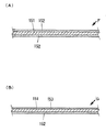
前記疑似接着フィルムシートは、図35(B)に示すように、例えばポリエチレンテレフタレート、二軸延伸ポリプロピレン、ポリエチレン、アセテート、ポリカーボネート、ナイロン、ポリエステル等の比較的剛性があり腰の強い材質からなる基材151の一方の面に疑似接着層153を形成し、残るもう一方の面に公知の感熱接着剤層152を形成した、3層構成のサーマルラミネート方式に対応したプリントラミネート用の疑似接着フィルムシートを好適に使用することができる。また基材151と疑似接着層153の2層構成のドライラミネート方式に対応したプリントラミネート用の疑似接着フィルムシートを使用しても構わない。 As shown in FIG. 35 (B), the pseudo adhesive film sheet is a base material made of a relatively rigid and strong material such as polyethylene terephthalate, biaxially stretched polypropylene, polyethylene, acetate, polycarbonate, nylon, polyester, and the like. 151. A pseudo-adhesive film sheet for print lamination corresponding to a three-layer thermal laminating system in which a
前記疑似接着フィルムシートは、例えば情報通信体を構成する印刷物の疑似接着予定面に被覆して、その後疑似接着予定面同士を折り合わせ疑似接着層同士を対向させて加圧或いは加熱・加圧処理を施すと剥離可能に接着するものである。そしてその後に対向面同士を引き剥がすと、疑似接着層の界面から剥離するか、或いは基材といずれかの疑似接着層との間から剥離するか、さらに前記両者の剥離が複合的に起こり、対向面同士を容易に剥離することができるのである。そして一旦剥離すると容易にもとの接着状態に復元することはできない。 The pseudo-adhesive film sheet is, for example, coated on a pseudo-adhesive planned surface of a printed material that constitutes an information communication body, and thereafter, the pseudo-adhesive planned surfaces are folded together so that the pseudo-adhesive layers are opposed to each other, and pressurization or heating / pressurization treatment When it is applied, it adheres in a peelable manner. And then, when the opposing surfaces are peeled apart, it peels off from the interface of the pseudo-adhesive layer, or peels off between the base material and any of the pseudo-adhesive layers, and further the peeling of both occurs in a complex manner, The opposing surfaces can be easily separated. And once peeled off, it cannot be easily restored to the original adhesive state.
本発明の情報通信体を構成する各紙片に使用される紙材は、上質紙、マットコート紙、グロスコート紙、合成紙その他の公知の用紙等を好適に使用することができる。マットコート紙やグロスコート紙のように表面処理が施されている塗工紙(特にマットコート紙)は、用紙表面に塗工される成分が紙繊維同士のバインダーの役を果たすため、水濡れに対しても解れたり或いは分断し難い用紙が好適に使用できるが、上質紙のように水濡れにより複数層に層間剥離を起こすものに対して特に本発明は優れた作用効果を発揮する。 As the paper material used for each piece of paper constituting the information communication body of the present invention, high-quality paper, matte coated paper, gloss coated paper, synthetic paper and other known papers can be suitably used. Coated paper (especially mat-coated paper) that has been surface-treated, such as mat-coated paper and gloss-coated paper, is wet with water because the components coated on the paper surface serve as a binder between the paper fibers. However, the present invention exhibits an excellent action and effect especially for those which cause delamination in a plurality of layers due to water wetting, such as high-quality paper.
本発明の開封縁辺に形成される段差の形状等に格別な制限はない。例えば開封縁辺に沿って一定の間隔で形成されていてもよく、或いは開封縁辺の上下何れかの箇所のコーナー部分で一方の紙片を切り欠くことにより形成しても構わない。 There is no particular restriction on the shape of the step formed on the opening edge of the present invention. For example, it may be formed at regular intervals along the opening edge, or may be formed by cutting out one piece of paper at a corner portion at any position above and below the opening edge.
また本発明で、面積の少ない側或いは多い側の紙片において、対向面側と逆側の面に延長され折り返して被覆される疑似接着フィルムシートの被覆面積にも格別な制限はない。開封縁辺から折り返し、逆側へ僅かに入り込んだ位置で被覆を止めておいても、或いは折り返された逆側のほぼ全面に被覆しても構わない。 In the present invention, there is no particular limitation on the covering area of the pseudo-adhesive film sheet that is extended and folded back to the surface opposite to the opposite surface side in the paper piece having a small area or a large area. The covering may be stopped at a position where it is folded back from the unsealed edge and slightly enters the reverse side, or it may be covered on almost the entire reverse side.
なお、疑似接着フィルムシートに関しては、既述の被覆後折り合わせて対向した疑似接着層同士から剥離するタイプの疑似接着フィルムシートの他に、例えば既述の基材の一方の面に熱可塑性或いは熱硬化性の樹脂を溶融押出しや塗工により剥離可能に積層した2層の積層フィルムシートの両外側に、公知の感熱接着剤層を形成した4層構成の疑似接着フィルムシートを使用しても構わない。この疑似接着フィルムシートの場合、前記基材と樹脂との間で剥離が行われる。 As for the pseudo-adhesive film sheet, in addition to the pseudo-adhesive film sheet of the type that is peeled off from the pseudo-adhesive layers that are folded and opposed after the above-mentioned coating, for example, thermoplastic or Even if a pseudo-adhesive film sheet having a four-layer structure in which a known thermosensitive adhesive layer is formed on both outer sides of a two-layer laminated film sheet in which a thermosetting resin is laminated so as to be peelable by melt extrusion or coating, I do not care. In the case of this pseudo-adhesive film sheet, peeling is performed between the base material and the resin.
本発明の水濡れに強い情報通信体によれば、開封の際に指で摘む対向紙片の両摘み部分が強靭な疑似接着フィルムシートで被覆されており、尚且つ面積の狭い紙片と折り返し片とを連接している部分の折りミシンにおいて疑似接着フィルムシートに貫通ミシンが形成されていないので、開封に際して疑似接着フィルムシートが前記貫通ミシンにより誤って破断されることはなく確実に開封を開始することができる。 According to the information communication body resistant to water wetting of the present invention, both the pinched portions of the opposing paper piece picked up with the fingers at the time of opening are covered with a tough pseudo-adhesive film sheet, and a paper piece with a small area and a folded piece Since the through sewing machine is not formed in the pseudo-adhesive film sheet in the folding sewing machine of the part connecting the two, the pseudo-adhesive film sheet is not accidentally broken by the through sewing machine at the time of opening, and the opening is surely started. Can do.
また、前記紙片と折り返し片の折りミシン部には貫通ミシンが形成されると共に、その部分を被覆する疑似接着フィルムシートも合わせて折り筋が形成されている。従って、本来であれば、両面にフィルムシートが被覆されて腰がきわめて強い状態の紙片を、想定した折りミシンから正確に折り込むことは非常に困難であるところ、既述の二重の折り筋が形成されているため極めてスムーズにしかも正確に折り畳むことが可能になる。 In addition, a penetration sewing machine is formed in the folding machine part of the paper piece and the folded piece, and a fold line is also formed together with the pseudo adhesive film sheet covering the part. Therefore, originally, it is very difficult to accurately fold a piece of paper that is covered with a film sheet on both sides and extremely stiff, from the assumed folding machine. Since it is formed, it can be folded very smoothly and accurately.
以下、本発明の実施の形態を図面に基づいて具体的に説明する。
[実施例1:水濡れに強い情報通信体1]
図1に示すように、本実施例の情報通信体J1は郵便はがきで、図2に示すように、折りミシン4、折りミシン5及び折り筋6の組み合わせからなる折手段を介して連接された第一紙片1、第二紙片2及び第三紙片3が、断面Z字状に折り畳まれている。そして第二紙片2と第三紙片3は、例えば図35(A)に示すように、ポリプロピレンからなる基材151の両面に公知の感熱接着剤層152を形成した完全接着フィルムシートFを介して剥離不能に接着され、また第一紙片1と第二紙片2においては図35(B)に示す疑似接着フィルムシートGを介して剥離可能に疑似接着されている。なお本実施例では複雑化を避けるため、各種フィルムシートを1層で表現している。Hereinafter, embodiments of the present invention will be described in detail with reference to the drawings.
[Example 1:
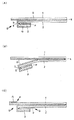
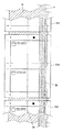
As shown in FIG. 1, the information communication body J1 of the present embodiment is a postcard and is connected via a folding means composed of a combination of the
図1(A)及び図3(A)に示すように、第一紙片1の表出面には、郵便切手欄、郵便番号欄及び受取人の住所氏名等が記載されている。また図1(B)及び図2(A)に示すように、第二紙片2と第一紙片1の幅の相違により段差部分Dが生じているが、この部分が情報通信体J1の剥離開封の端緒となる。なお、図1(B)において、第一紙片1の右側端の表出面(疑似接着フィルムシートGにより被覆されている)と第二紙片2の表出面には宣伝広告等の一般情報(図示は省略されている)が記載されていてもよい。 As shown in FIG. 1 (A) and FIG. 3 (A), a postage stamp field, a postal code field, a recipient's address name, and the like are written on the surface of the
この郵便はがきの受取人は、図2(B)に示すように、前記段差を形成している第一紙片1と第二紙片2及び第二紙片2の端部で折り返されて完全接着フィルムシートFで剥離不能に接着している第三紙片3を指で摘み引き剥がすことにより、第一紙片1と第二紙片2の間に介在する疑似接着フィルムシートG同士の間から剥離開封することができる。 As shown in FIG. 2B, the recipient of this postcard is folded at the end of the
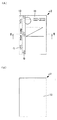
開封後の情報通信体J1は、図3に示すように第一紙片1と第二紙片2が折りミシン4で連接された状態で平面に展開される。そして図3(B)に示すように、隠蔽されていた内部の個人情報等(図示は省略されている)を透明或いは半透明の疑似接着フィルムシートGを透して視認することができるのである。 As shown in FIG. 3, the information communication body J <b> 1 after opening is developed on a plane in a state where the
なお、前記剥離開封の端緒となる段差部分Dは図2に示すように、指で摘む各紙片の両端部が確実に疑似接着フィルムシートGで被覆され補強されている。従って、仮に情報通信体J1が水濡れを起こしたり水中で紙繊維が解れたり破断し易い状態であっても、開封に際して一切問題は発生し得ない。そして一旦剥離を開始した疑似接着フィルムシートG同士は、最後まで連続的に剥離することができる。 In addition, as shown in FIG. 2, the step part D used as the beginning of the said peeling opening is reliably reinforced by covering the both ends of each paper piece picked with a finger with the pseudo-adhesive film sheet G. Accordingly, even if the information communication body J1 is in a state where it is wetted or the paper fibers are easily unwound or broken in the water, no problem can be caused at the time of opening. And the pseudo-adhesive film sheets G once started to peel can be continuously peeled to the end.
図2(A)において、折りミシン4及び5は紙片のみを貫通している。そして疑似接着フィルムGが前記貫通している折りミシン4及び5を被覆して保護しているため、開封に際して破断等の支障が起こることはない。また疑似接着フィルムGにより腰が強くなり、そのため折り辛くなる欠点を前記紙片を貫通して形成された折ミシン4及び5が相殺している。さらに両面にフィルムシートが被覆されより腰が強くなった折りミシン5部分には、折筋6が前記にも増して折り辛くなっている欠点を相殺している。 In FIG. 2A, the
なお、第一紙片1の段差部分Dには第二紙片2と対向する側に疑似接着フィルムシートGが被覆されているが、図2(C)における矢印Pに示すように第一紙片1の表出面側へ折り返され延長されて被覆されていても構わない。また第二紙片2と第三紙片3を剥離不能に接着している完全接着フィルムシートFは、矢印Qに示すように第二紙片2に対向する第三紙片3よりも幅広にはみ出す状態に余裕を持って被覆されていても構わない。 The step portion D of the
[実施例2:水濡れに強い情報通信体2]
図4及び図5に示すように、本実施例の情報通信体J2は郵便はがきで、折りミシン14及び15で連接された第一紙片11、第二紙片12及び第三紙片13が断面Z字状に折り畳まれている。そして各紙片同士は疑似接着フィルムシートGを介して、剥離可能に疑似接着されている。[Example 2:
As shown in FIGS. 4 and 5, the information communication body J2 of this embodiment is a postcard, and the
図4(A)に示すように、第一紙片11の表出面には、郵便切手欄、郵便番号欄及び受取人の住所氏名等が記載されている。また図5に示すように、左端部に沿って第三紙片13の端部が突出しているため、その表出した部分に「POST CARD」の文言が外部から視認できるように表示されている。そして各紙片の幅の相違により段差部分D(各紙片の摘み部分が疑似接着フィルムシートGにより被覆されている)が生じているが、この部分が情報通信体J2の剥離開封の端緒となる。そして図4(B)に示すように、第三紙片13の表出面には宣伝広告等の一般情報(図示は省略されている)が記載されている。 As shown in FIG. 4 (A), a postage stamp field, a postal code field, a recipient's address name, and the like are written on the exposed surface of the
この郵便はがきの受取人は、前記段差部分Dを形成している第一紙片11と連接している第二紙片12及び第三紙片13の両者を指で摘み、対向している第二紙片12と第三紙片13の間に介在する疑似接着フィルムシートG同士の間から両紙片を剥離開封することができる。 The recipient of this postcard picks both the
開封後の情報通信体J2は、図6に示すように各紙片が各折りミシンで連接された状態で平面に展開される。そして図6(A)に示すように、第三紙片13と第二紙片12の対向面間に隠蔽されていた内部の個人情報等(図示は省略されている)を透明或いは半透明の疑似接着フィルムシートGを透して視認することができるのである。 As shown in FIG. 6, the information communication body J2 after being opened is unfolded on a plane in a state where each piece of paper is connected by each folding sewing machine. Then, as shown in FIG. 6A, the internal personal information (not shown) concealed between the opposing surfaces of the
なお、図6(B)に示すように、第一紙片11と第二紙片12の対向面には何も情報が記載されておらず白紙の状態である。従ってこの両葉片はあえて剥離する必要がなく、最終的に第二紙片12と第三紙片11間を剥離する見開き2頁の形態と考えて構わない。既述の通り第一紙片11と第二紙片12の剥離を考慮しない場合、前記白紙以外に寒色系ベタ印刷や各種意味のないパターン等により、情報通信体の外部から透かして内部の情報を確認し辛くする操作を行っても構わない。 As shown in FIG. 6B, no information is written on the opposing surfaces of the
また、前記剥離の端緒となる段差部分Dは図5に示すように、指で摘む両端部が確実に疑似接着フィルムシートGで被覆され補強されている。従って、仮に情報通信体J2が水濡れを起こしたり水中にあって紙繊維が解れたり破断し易い状態であっても、開封に際して一切問題は発生し得ない。そして一旦剥離を開始した第二紙片12と第三紙片13間に介在する疑似接着フィルムシートG同士は、最後まで連続的に剥離することができる。 Further, as shown in FIG. 5, the stepped portion D, which is the beginning of the peeling, is securely covered with a pseudo-adhesive film sheet G at both ends picked up by fingers. Therefore, even if the information communication body J2 is wetted or is in water and the paper fibers are easily unwound or broken, no problem can occur when opening. And the pseudo-adhesive film sheets G interposed between the
図5において、折りミシン14及び15は紙片のみを貫通している。そして疑似接着フィルムGが前記貫通している折りミシン14及び15を被覆して保護しているため、開封に際して破断等の支障が起こることはない。また疑似接着フィルムGにより腰が強くなり、そのため折り辛くなる欠点を前記紙片を貫通して形成された折ミシン14及び15が相殺している。さらに両面にフィルムシートが被覆されより腰が強くなった折りミシン14部分には、折筋16が前記にも増して折り辛くなっている欠点を相殺している。 In FIG. 5, the
なお、第三紙片13の段差部分には第二紙片12と対向する側に疑似接着フィルムシートGが被覆されているが、実施例1の図2(C)における矢印Pと同様に第三紙片13の表出側へ折り返され延長されて被覆されていても構わない。 The step portion of the
[実施例3:水濡れに強い情報通信体3]
図7及び図8に示すように、本実施例の情報通信体J3は封書で、折りミシン24及び25で連接された第一紙片21、第二紙片22及び第三紙片23が断面Z字状に折り畳まれている。そして各紙片同士は疑似接着フィルムシートGを介して、剥離可能に疑似接着されている。[Example 3:
As shown in FIGS. 7 and 8, the information communication body J3 of this embodiment is a sealed letter, and the
図7(A)及び図8に示すように、第一紙片21の表出面には郵便切手欄、郵便番号欄が記載され、受取人の住所氏名等が印字されたラベルが貼付されている。そして左端部に沿って第三紙片23の端部が表出し段差を形成している。同様に図7(B)及び図8に示すように、第三紙片23の表出面には宣伝広告等の一般情報(図示は省略されている)が記載されると共に左端部に沿って第一紙片21の端部が表出し段差を形成している。 As shown in FIGS. 7A and 8, a postage stamp field and a postal code field are written on the exposed surface of the
この封書の受取人は、例えば前記段差部分Dを形成している第一紙片21と連接している第二紙片22折り返し部分(折りミシン24)及び第三紙片23の突出した端部を指で摘み、対向している第二紙片22と第三紙片23の間に介在する疑似接着フィルムシートG同士の間から両紙片を剥離開封する。その後もう一方の段差部分Dの第一紙片21と第二紙片22間を、前記同様に各々の紙片の摘み部分を被覆している疑似接着フィルムシートGを摘んで剥離開封する。このようにして全ての紙片が平面に展開される。
なお本実施例の情報通信体J3は図8に示すように、段差形成部が2箇所発生しているので、何れから開封を始めても構わない。For example, the recipient of the sealed letter uses his / her fingers to turn the
In the information communication body J3 of this embodiment, as shown in FIG. 8, since two step forming portions are generated, the opening may be started from any position.
開封後の情報通信体J3は、図9に示すように各紙片が各折りミシンで連接された状態で平面に展開される。そしてそれぞれ対向面間に隠蔽されていた内部の個人情報等(図示は省略されている)を透明或いは半透明の疑似接着フィルムシートGを透して視認することができるのである。 As shown in FIG. 9, the information communication body J3 after opening is unfolded on a plane in a state in which each piece of paper is connected by each folding sewing machine. And the internal personal information etc. (not shown) concealed between the opposing surfaces can be seen through the transparent or translucent pseudo-adhesive film sheet G.
また、前記剥離開封の端緒となる段差部分Dは図8に示すように、指で摘む両端部が確実に疑似接着フィルムシートGで被覆され補強されている。従って、仮に情報通信体J3が水濡れを起こしたり水中にあって紙繊維が解れたり破断し易い状態であっても、開封に際して一切問題は発生し得ない。そして一旦剥離を開始した各紙片間に介在する疑似接着フィルムシートG同士は、最後まで連続的に剥離することができる。 Further, as shown in FIG. 8, the stepped portion D that is the beginning of the peel-opening is securely reinforced by being covered with a pseudo-adhesive film sheet G at both ends that are picked by a finger. Therefore, even if the information communication body J3 is wetted or is in the water and the paper fiber is easily unwound or broken, no problem can occur at the time of opening. And the pseudo-adhesive film sheets G interposed between the paper pieces once started to peel can be continuously peeled to the end.
なお、実施例1における図2(C)の矢印Pと同様に、第一紙片21及び第三紙片23の折りミシン24及び25と逆側の端部において、疑似接着フィルムシートGが表出面側へ折り返され延長されて被覆されていても構わない。 As in the case of the arrow P in FIG. 2C in Example 1, the pseudo adhesive film sheet G is exposed on the side opposite to the
[実施例4:長尺状シートによる水濡れに強い情報通信体J1の製造方法]
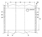
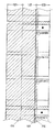
本実施例で使用する長尺状シートS1は、図10に示すように第一紙片31、第二紙片32及び第三紙片33が折りミシン34、35を介して横方向に連接された単位シートt1が、上下の切取線36を介して縦方向に連接したものである。そして第一紙片31と第三紙片33の外側には切取線37(必ずしも表示される必要はなくミシン等に代えても構わない)を介してマージナル孔38が設けられたマージナル部分39が連接されている。[Example 4: Manufacturing method of information communication body J1 resistant to water wetting with a long sheet]
As shown in FIG. 10, the long sheet S <b> 1 used in this embodiment is a unit sheet in which a
図10(A)に示すように、第一紙片31表面には郵便切手欄、郵便番号欄及び受取人の住所氏名等が記載されている。また第二紙片32の最終的に表出する面(第三紙片33の折り返しで隠れない部分)には、広告宣伝等の一般情報(図示は省略されている)が記載されている。 As shown in FIG. 10 (A), a postage stamp field, a postal code field, a recipient's address name, and the like are written on the surface of the
図10(B)に示すように、第一紙片31及び第二紙片32の裏面には、個人情報等(図示は省略されている)が記載され、第三紙片33の裏面には例えば「ここから剥がす」等の開封を促す文言等(図示は省略されている)が記載されている。 As shown in FIG. 10B, personal information or the like (not shown) is written on the back surfaces of the
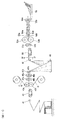
既述の通り構成された長尺状シートS1は、上下の切取線から蛇腹に折り畳まれてブロック状態で図11に示す製造工程の最上流である左下に配置される。そして最上面の単位シートt1から順番に上方のサポートローラ41へ引き上げられると、ほぼ水平方向へ向きを変えて右側に配置されているピントラクタ42のピンとマージナル孔38とを合致させてさらに右側のラミネート装置へと牽引される。 The elongate sheet S1 configured as described above is folded in a bellows from the upper and lower cut lines and arranged in the lower left, which is the most upstream of the manufacturing process shown in FIG. When the uppermost unit sheet t1 is pulled up to the
ラミネート装置は一対のヒートローラ43a、43bにより構成され、上方に待機しているロールからは完全接着フィルムシートFが、そして下方からは疑似接着フィルムシートGが繰り出され、それぞれ一対のヒートローラ43a、43bにおいて、図12(A)及び(B)に示すように、通過する長尺状シートS1の完全接着予定面と疑似接着予定面に整合されると共に剥離不能に被覆されるのである。 The laminating apparatus is composed of a pair of
それぞれのフィルムシートが被覆された長尺状シートS1は、右側に配置されている例えば筋入れ刃45a及びバックアップローラ45bとからなる折り筋形成装置により、図13に示すように当初から形成されている折りミシン35の上から、疑似接着フィルムシートGと共に折り筋40が形成される。さらにスリット刃46aとバックアップローラ46bとからなる第一の切除装置により、図13に示すように第三紙片33の外側のマージナル部分39が切取線37から切除された後に右側に配置されている一対のニップローラ47a、47bによりさらに下流へと送り出されるのである。 The long sheet S1 covered with each film sheet is formed from the beginning as shown in FIG. 13 by a crease forming device including, for example, a
なお、前記折り筋形成装置及び切除装置は共通のバックアップローラを使用して、その上に筋入れ刃25a及びスリット刃46aを平行に設置すれば、前記折り筋の形成及びマージナル部分39の切除を同時に行うことができる。
また前記切除装置は、例えば一対のニップローラ47a、47bと折り畳み装置48の間に配置したインタースタッカ等の切除装置に替えても構わない。The crease forming device and the excision device use a common backup roller, and if the creasing blade 25a and the
The excision device may be replaced with an excision device such as an inter-stacker disposed between the pair of nip
その後長尺状シートS1は、右側に配置されている長尺状シート専用の折り畳み装置48(アングル、くせ折り機等と称されている)により図14に示すように、ほぼ断面Z字状に折り畳まれると共にサポートローラ49でほぼ水平に向きを変えた後に、更に右側に配置しているピントラクタ50に牽引され、スリット刃51aとバックアップローラ51bとからなる第二の切除装置により残っているマージナル部分39を切除され、右側に配置されている断裁装置へと送り込まれる。 Thereafter, the long sheet S1 is formed into a substantially Z-shaped cross section as shown in FIG. 14 by a folding device 48 (referred to as an angle, a folding folder, etc.) dedicated to the long sheet disposed on the right side. After being folded and turned almost horizontally by the
本実施例では長尺状シートS1の両外側マージナル部分39の切除を第一及び第二の切除装置を使用して段階的に切除しているが、並列に並べられた第二の切除装置において両側のマージナル部分39を同時に切除しても構わない。 In this embodiment, the outer
前記断裁装置は、例えばダイカットローラ52aとバックアップローラ52bとからなり、通過する長尺状シートS1を単位シートt1の上下の切取線36で断裁して、図1及び図2(A)に示す状態の個別の単位シートt1に仕上げる。そして前記個別の単位シートt1は次に右側に配置された一体化装置へ順次送り込まれる。 The cutting device includes, for example, a
前記一体化装置は、一対の搬送ローラ53a、53bと上下に対向して配置された一対のヒータパネル54a、54bが進行方向に対して交互に配置されており、その中を通過する単位シートt1は十分加熱される。その後最終の排出部分に配置されている一対のニップローラ55a、55bにより加圧されて、折り畳まれて対向する完全接着フィルムシートF同士は剥離不能に、また疑似接着フィルムシートG同士は剥離可能に接着され全体として一体化されるのである。 In the integrated device, a pair of
このようにして完成した情報通信体J1は排出された後にベルトコンベア等からなるスタッカ56に順次積載され、その後郵便番号に沿った仕分け等の作業を経て投函される。 The information communication body J1 completed in this manner is sequentially stacked on a
[実施例5:長尺状シートによる水濡れに強い情報通信体J2の製造方法]
本実施例で使用する長尺状シートS2は、図15に示すように第一紙片61、第二紙片62及び第三紙片63が折りミシン64、65を介して横方向に連接された単位シートt2が、上下の切取線66を介して縦方向に連接したものである。そして第一紙片61と第三紙片63の外側には切取線67を介してマージナル孔68が設けられたマージナル部分69が連接されている。[Example 5: Method of manufacturing information communication body J2 resistant to water wetting with a long sheet]
As shown in FIG. 15, the long sheet S2 used in this embodiment is a unit sheet in which a
図15(A)に示すように、第一紙片61表面には情報通信体J2の完成後に表出する左側端に沿って「POST CARD」又は「郵便はがき」等の表示がなされ、折り畳み後第二紙片62と対向して隠蔽される部分には秘密を要する個人情報等(図示は省略されている)が記載されている。また第二紙片62表面には、個人情報等(図示は省略されている)が記載され、第三紙片63表面には郵便切手欄、郵便番号欄及び受取人の住所氏名等が記載されている。 As shown in FIG. 15 (A), “POST CARD” or “postcard” or the like is displayed on the surface of the
図15(B)に示すように、第三紙片63及び第二紙片62の裏面には、何も情報が記載されておらず白紙の状態である。そして第一紙片61の裏面には、例えば広告宣伝等の一般情報(図示は省略されている)が記載されている。 As shown in FIG. 15B, no information is written on the back surfaces of the
既述の通り構成された長尺状シートS2は、上下の切取線66から蛇腹に折り畳まれてブロック状態で図11に示す製造工程の最上流である左下に配置される。そして最上面の単位シートt2から順番に上方のサポートローラ41へ引き上げられると、ほぼ水平方向へ向きを変えて右側に配置されているピントラクタ42のピンとマージナル孔38とを合致させてさらに右側のラミネート装置へと牽引される。 The long sheet S2 configured as described above is folded in a bellows from the upper and
ラミネート装置は一対のヒートローラ43a、43bにより構成され、上下方に待機しているロールからは疑似接着フィルムシートGが繰り出され、それぞれ一対のヒートローラ43a、43bにおいて、図16(A)及び(B)に示すように、通過する長尺状シートS2の表裏面の各疑似接着予定面に整合されると共に剥離不能に被覆されるのである。なお図16(B)側には完全接着フィルムシートFが被覆されても構わない。 The laminating apparatus is composed of a pair of
それぞれのフィルムシートが被覆された長尺状シートS2は、右側に配置されている例えば筋入れ刃45a及びバックアップローラ45bとからなる折り筋形成装置により、図17に示すように当初から形成されている折りミシン65の上から、疑似接着フィルムシートGと共に折り筋66が形成される。そしてさらにスリット刃46aとバックアップローラ46bとからなる第一の切除装置により、図17に示すように第三紙片63の外側のマージナル部分69が切取線67から切除された後に、右側に配置されている一対のニップローラ47a、47bによりさらに下流へと送り出されるのである。 The long sheet S2 covered with each film sheet is formed from the beginning as shown in FIG. 17 by a crease forming device including, for example, a
なお、前記折り筋形成装置及び切除装置は、共通のバックアップローラを使用して、その上にミシン刃44a、筋入れ刃45a及びスリット刃46aを平行に設置すれば、前記ミシンの形成、筋入れの形成及びマージナル部分69の切除を同時に行うことができる。
また前記切除装置は、例えば一対のニップローラ47a、47bと折り畳み装置48の間に配置したインタースタッカ等の切除装置に替えても構わない。The folding line forming device and the resecting device use a common backup roller, and if the sewing machine blade 44a, the
The excision device may be replaced with an excision device such as an inter-stacker disposed between the pair of nip
その後長尺状シートS2は、右側に配置されている折り畳み装置48により図18に示すように、ほぼ断面Z字状に折り畳まれると共にサポートローラ49でほぼ水平に向きを変えた後に、更に右側に配置されているピントラクタ50に牽引され、スリット刃51aとバックアップローラ51bとからなる第二の切除装置により残りのマージナル部分69を切除されると、右側に配置されている断裁装置へと送り込まれる。 Thereafter, as shown in FIG. 18, the long sheet S2 is folded into a substantially Z-shaped cross-section as shown in FIG. When the remaining
本実施例では長尺状シートS2の両外側マージナル部分79の切除を第一及び第二の切除装置を使用して段階的に切除しているが、並列に並べられた第二の切除装置において両側のマージナル部分79を同時に切除しても構わない。
なお、断裁装置以降の工程は既述の実施例4と同様なので省略する。In this embodiment, both outer
Since the processes after the cutting apparatus are the same as those in the fourth embodiment, the description thereof will be omitted.
[実施例6:長尺状シートよる水濡れに強い情報通信体J3の製造方法]
本実施例で使用する長尺状シートS3は、図19に示すように第一紙片71、第二紙片72及び第三紙片73が折りミシン74及び75を介して横方向に連接された単位シートt3が、上下の切取線76を介して縦方向に連接したものである。そして第一紙片71と第三紙片73の外側には切取線77を介してマージナル孔78が設けられたマージナル部分79が連接されている。[Example 6: Manufacturing method of information communication body J3 resistant to water wetting with long sheet]
As shown in FIG. 19, the long sheet S3 used in this embodiment is a unit sheet in which a
そして第一紙片71及び第二紙片72の表面には個人情報(図示は省略されている)が記載され、第三紙片73の表面には郵便切手欄、郵便番号欄及び受取人の住所氏名等が記載されている。なお、前記第三紙片73の表面の受取人の住所氏名等は、加工工程前の長尺状シートS3の段階で予めプリンタ等で記載しても構わないが、情報通信体J3に仕上がった後で別工程により直接前記表面に記載したり、或いは住所指名等を記載した宛名ラベルを貼付しても構わない。 The personal information (not shown) is written on the surface of the
また図示は省略されているが、第二紙片72及び第三紙片73の裏面には、個人情報等が記載され、情報通信体J3の完成後に表出する第一紙片71の裏面には、例えば広告宣伝等の一般情報が記載されている。 Although not shown, personal information or the like is written on the back surfaces of the
既述の通り構成された長尺状シートS3は、上下の切取線76から蛇腹に折り畳まれてブロック状態で図11に示す製造工程の最上流である左下に配置され、既述の実施例4及び5と同様の工程を経て図20に示すように、折りミシン74及び75を被覆する各疑似接着フィルムシートGと共に折り筋80及び81が形成された後に最終的に情報通信体J3の形態に仕上げられる。なお、本実施例でもマージナル部分79の切除を第一及び第二の切除装置を使用して段階的に切除しているが、並列に並べられた第二の切除装置において両側のマージナル部分79を同時に切除しても構わない。 The long sheet S3 configured as described above is folded in a bellows from the upper and
[実施例7:枚葉状シートによる水濡れに強い情報通信体J1の製造方法]
本実施例で使用する枚葉状シートS4は、図21に示すように第一紙片91、第二紙片92及び第三紙片93が二点鎖線で示される2箇所の折りミシン形成予定線94及び95(両者とも必ずしも表示される必要はない)を介して横方向に連接された単位シートt4が2丁印刷されている。そして各々の単位シートt4の周囲は縦方向の余白部分Xと横方向の余白部分Yに囲まれている。[Example 7: Manufacturing method of information communication body J1 resistant to water wetting with a sheet-like sheet]
As shown in FIG. 21, the sheet S4 used in the present embodiment has two folding machine formation scheduled
そして第一紙片91表面には郵便切手欄、郵便番号欄及び受取人の住所氏名等が記載されている。また第二紙片92の第三紙片93の最終的に表出する面(折り返しで隠れない部分)には、広告宣伝等の一般情報(図示は省略されている)が記載されている。 On the surface of the
また図22に示すように、第一紙片91及び第二紙片92の裏面には、個人情報等(図示は省略されている)が記載され、第三紙片93の裏面には例えば「ここから剥がす」等の開封を促す文言等(図示は省略されている)が記載されている。 Further, as shown in FIG. 22, personal information or the like (not shown) is written on the back surface of the
既述の通り構成された枚葉状シートS4は、図23に示す製造工程の最上流である左の紙載せ台に載置される。そして最上面の枚葉状シートS4から順番に、吸着パッド等からなる繰り出し機構101により吸い上げられ、右側のテーブルへ繰り出される。そして右側に配置されている一対のニップローラ102a、102bにより更に右側に配置された、ミシン刃103aとバックアップローラ103bとからなる折りミシン形成装置へと送り込まれ折り手段形成予定線に折りミシン94及び95が形成された後に、さらに右側に配置されているラミネート装置へと送り込まれる。 The sheet S4 configured as described above is placed on the left paper platform which is the most upstream of the manufacturing process shown in FIG. Then, in order from the uppermost sheet S4, the sheet is sucked up by the
ラミネート装置は一対のヒートローラ104a、104bにより構成され、上方に待機しているロールからは完全接着フィルムシートFが、そして下方に待機しているローラから疑似接着フィルムシートGが繰り出され、それぞれ一対のヒートローラ104a、104bにおいて、図24に示すように、通過する枚葉状シートS4の完全接着予定面と疑似接着予定面に整合されると共に剥離不能に被覆されるのである。 The laminating apparatus is composed of a pair of
それぞれのフィルムシートが被覆された枚葉状シートS4は、図25に示すように、右側に配置されている例えば、筋入れ刃105a及びバックアップローラ105bとからなる折り筋形成装置により、上流工程の折りミシン形成装置により形成された折りミシン95の上から前記折りミシン9を被覆する疑似接着フィルムシートGと共に折り筋96が形成され、さらにスリット刃106aとバックアップローラ106bとからなる切除装置(並列に2セット配置されている)により縦方向の余白部分Xを切除した後に右側に配置されている一対のニップローラ107a、107bによりさらに下流へと送り出されるのである。 As shown in FIG. 25, the sheet-like sheet S4 covered with each film sheet is folded in the upstream process by a folding line forming device that is arranged on the right side, for example, including a creasing blade 105a and a backup roller 105b. A
なお、前記折り筋形成装置及び切除装置は共通のバックアップローラを使用して、その上に筋入れ刃105a及びスリット刃106aを平行に設置すれば、前記筋入れの形成及び縦方向の余白部分Xの切除を同時に行うことができる。 If the crease forming device and the resecting device use a common backup roller, and the crease blade 105a and the slit blade 106a are installed in parallel thereon, the formation of the crease and the vertical margin X Resection can be performed simultaneously.
その後長尺状シートS4は、右側に配置されている折り畳み装置108により図26及び図2(A)に示すように、ほぼ断面Z字状に折り畳まれると共にサポートローラ109でほぼ水平に向きを変えた後に、右側に配置している一対のニップローラ110a、110bにより更に右側に配置されている断裁装置へと送り込まれる。 Thereafter, as shown in FIGS. 26 and 2A, the long sheet S4 is folded into a substantially Z-shaped cross section by the
前記断裁装置は、例えば断裁刃112aと固定刃112bとからなり、通過する長尺状シートS4の横方向の余白部分Yを断裁して個別の単位シートt4毎に仕上げる。前記横方向の余白部分Yの断裁については、例えば断裁装置の上流にセンサ111を配置しておいて、図26に示すように、初めに中央の枚葉状シートS4に記載されたマークM1を読み取ると最初の断裁位置96までの距離をカウントして断裁する。続いて97、98及び99までの距離をそれぞれカウントして断裁動作を繰り返し、続く枚葉状シートS4に記載されたマークM2を読み取ると前記動作を繰り返すよう電気的に制御されている。このようにして前後する枚葉状シートS4の横方向の余白部分Y+Z(前後する枚葉状シートS4の間隙の表出した疑似接着フィルムシート)+Yと、単位シートt4間の横方向の余白部分Yを順次断裁されて個別となった単位シートt4は、さらに右側に配置された一体化装置へと送り込まれる。
なお、一体化装置以降の工程は既述の実施例と同様なので省略する。The cutting device includes, for example, a
In addition, since the process after an integrated apparatus is the same as that of the above-mentioned Example, it abbreviate | omits.
[実施例8:枚葉状シートによる水濡れに強い情報通信体J2の製造方法]
本実施例で使用する枚葉状シートS5は、図27に示すように第一紙片121、第二紙片122及び第三紙片123が二点鎖線で示される2箇所の折りミシン形成予定線(両者とも必ずしも表示される必要はない)を介して横方向に連接された単位シートt5が、3丁印刷されている。そして各々の単位シートt5の周囲は縦方向の余白部分Xと横方向の余白部分Yに囲まれている。[Example 8: Manufacturing method of information communication body J2 resistant to water wetting by sheet-like sheet]
As shown in FIG. 27, the sheet-like sheet S5 used in the present embodiment has two folding sewing machine formation planned lines (both of which are indicated by two-dot chain lines in which the
そして第一紙片121表面には。情報通信体J2完成後に表出する左側端に沿って「POST CARD」又は「郵便はがき」等の表示がなされ、折り畳み後第二紙片122と対向して隠蔽される部分には秘密を要する個人情報等(図示は省略されている)が記載されている。また第二紙片122表面には、個人情報等(図示は省略されている)が記載され、第三紙片123表面には郵便切手欄、郵便番号欄及び受取人の住所氏名等が記載されている。And on the surface of the
また図28に示すように、第三紙片123及び第二紙片122の裏面には、何も情報が記載されておらず白紙の状態である。そして第一紙片121の裏面には、例えば広告宣伝等の一般情報(図示は省略されている)が記載されている。 As shown in FIG. 28, no information is written on the back surfaces of the
既述の通り構成された枚葉状シートS5は、図23に示す製造工程の最上流である左の紙載せ台に載置される。そして最上面の枚葉状シートS5から順番に、吸着パッド等からなる繰り出し機構101により吸い上げられ、右側のテーブルへ繰り出される。そして右側に配置されている一対のニップローラ102a、102bにより更に右側に配置された、ミシン刃103aとバックアップローラ103bとからなる折りミシン形成装置(並列に2セット配置されている)へと送り込まれ折りミシン形成予定線に折りミシン94及び95が形成された後に、さらに右側に配置されているラミネート装置へと送り込まれる。 The sheet S5 configured as described above is placed on the left paper platform which is the most upstream of the manufacturing process shown in FIG. Then, in order from the uppermost sheet S5, the sheet is sucked up by the
ラミネート装置は一対のヒートローラ103a、103bにより構成され、上下方に待機している各ロールから疑似接着フィルムシートGが繰り出され、それぞれ一対のヒートローラ103a、103bにおいて、図29に示すように、通過する枚葉状シートS5の各疑似接着予定面に整合されると共に剥離不能に被覆されるのである。 The laminating apparatus is composed of a pair of
それぞれのフィルムシートが被覆された枚葉状シートS4は、図30に示すように、右側に配置されている例えば、筋入れ刃105a及びバックアップローラ105bとからなる折り筋形成装置(並列に2セット配置されている)により、上流工程の折りミシン形成装置により形成された折りミシン124及び125の上から前記折りミシン124及び125を被覆する疑似接着フィルムシートGと共に折り筋132及133が形成され、さらにスリット刃106aとバックアップローラ106bとからなる切除装置(並列に2セット配置されている)により縦方向の余白部分Xを切除した後に右側に配置されている一対のニップローラ107a、107bによりさらに下流へと送り出されるのである。 As shown in FIG. 30, the sheet-like sheet S4 coated with each film sheet is, for example, a folding line forming device (two sets arranged in parallel) that are arranged on the right side. Fold
なお、前記折り筋形成装置及び切除装置は共通のバックアップローラを使用して、その上に筋入れ刃105a及びスリット刃106aを平行に設置すれば、前記ミシンの形成、筋入れの形成及び縦方向の余白部分Xの切除を同時に行うことができる。 If the crease forming device and the resecting device use a common backup roller, and the scoring blade 105a and the slit blade 106a are installed in parallel on the same, the sewing machine, the scoring and the longitudinal direction are formed. The blank portion X can be removed simultaneously.
その後枚葉状シートS5は、右側に配置されている折り畳み装置108により図31及び図5に示すように、ほぼ断面Z字状に折り畳まれると共にサポートローラ109でほぼ水平に向きを変えた後に、更に右側に配置している一対のニップローラ110a、110bにより更に右側に配置されている断裁装置へと送り込まれる。 Thereafter, the sheet S5 is folded into a substantially Z-shaped cross-section by the
前記断裁装置は、例えば断裁刃112aと固定刃112bとからなり、通過する枚葉状シートS5の横方向の余白部分Yを断裁して個別の単位シートt5に仕上げる。前記横方向の余白部分Yの断裁については、例えば断裁装置の上流にセンサ111を配置しておいて、図31に示すように、初めに中央の枚葉状シートS5に記載されているマークM1を読み取ると最初の断裁位置126までの距離をカウントして断裁する。続いて127、128、129、130及び131までの距離をそれぞれカウントして断裁動作を繰り返し、続く枚葉状シートS5に記載されたマークM2を読み取ると前記動作を繰り返すよう電気的に制御されている。このようにして横方向の余白部分Y+Z(前後する枚葉状シートS4の間隙の疑似接着フィルムシート)+YとYを順次断裁され個別となった単位シートt4は、さらに右側に配置された一体化装置へと送り込まれる。
なお、一体化装置以降の工程は既述の実施例と同様なので省略する。The cutting device includes, for example, a
In addition, since the process after an integrated apparatus is the same as that of the above-mentioned Example, it abbreviate | omits.
[実施例9:枚葉状シートによる水濡れに強い情報通信体J3の製造方法]
本実施例で使用する枚葉状シートS6は、図32に示すように第一紙片141、第二紙片142及び第三紙片143が二点鎖線で示す2箇所の折りミシン形成予定線を介して横方向に連接された単位シートt6が、2丁印刷されている。そして各々の単位シートt6の周囲は縦方向の余白部分Xと横方向の余白部分Yに囲まれている。[Example 9: Manufacturing method of information communication body J3 resistant to water wetting by sheet-like sheet]
As shown in FIG. 32, the sheet-like sheet S6 used in the present embodiment is disposed horizontally through two folding sewing machine formation planned lines indicated by two-dot chain lines on the
そして折り畳み後に対向して隠蔽される第一紙片141及び第二紙片142の表面には、例えば秘密を要する個人情報等(図示は省略されている)が記載されている。また第三紙片143の表面には、郵便切手欄、郵便番号欄及び受取人の住所氏名等が記載されている。なお前記受取人の住所氏名等は、情報通信体J3の完成後に別工程でプリンタ等により印字を施したり、前記印字が完了した宛名ラベルを貼り込んでも構わない。 Then, on the surfaces of the
なお、図示は省略されているが、情報通信体J3の完成後に表出する第一紙片141の裏面には、例えば広告宣伝等の一般情報が記載されている。そして折り畳み後に対向して隠蔽される第二紙片142及び第三紙片143の裏面には、例えば秘密を要する個人情報等が記載されている。 In addition, although illustration is abbreviate | omitted, general information, such as advertisement, is described in the back surface of the
既述の通り構成された枚葉状シートS6は、図23に示す製造工程の最上流である左の紙載せ台に載置される。そして最上面の枚葉状シートS6から順番に、吸着パッド等からなる繰り出し機構101により繰り出され、折りミシン形成装置により折りミシン144及び145が形成された後に、図33に示すように疑似接着フィルムシートGが被覆される。その後図34に示すように、前記折りミシン144及び145と折りミシン144及び145を被覆する疑似接着フィルムシートの両者ともに折り筋形成装置により折り筋146、147が形成されると共に、切除装置により縱方向の余白Xが切除される。そして図8に示すように断面Z字状に折り畳まれて既述の実施例7及び8と同様の工程を経ることにより情報通信体J3に仕上げられる。 The sheet S6 configured as described above is placed on the left paper platform which is the most upstream of the manufacturing process shown in FIG. Then, after being fed out from the topmost sheet S6 by the
なお、本発明は、上記実施例に限定されるものではない。
例えば、各実施例で折り手段形成予定線に施される折りミシンを、予め別工程でスリッター等により各種用紙に施しておくことにより、折りミシン形成装置を省略しても構わない。In addition, this invention is not limited to the said Example.
For example, the folding sewing machine forming apparatus may be omitted by applying the folding sewing machine applied to the folding means formation planned line in each embodiment to various sheets in advance in a separate process using a slitter or the like.
J1、J2、J3 情報通信体
S1、S2、S3 長尺状シート
S4、S5、S6 枚葉状シート
F 完全接着フィルムシート
G 疑似接着フィルムシート
D 段差部分
1、2、3、11、12、13、21、22、23、31、32、33、61、62、63、71、72、73、91、92、93、121、122、123、141、142、143 紙片
4、5、14、15、24、25、34、35、64、65、74、75、94、95、124、125、144、145 折りミシン
6、16、26、27、40、66、80、81、96、132、146、147 折り筋
36、37、66、67、76、77 切取線
38、68、78 マージナル孔
39、69、79 マージナル部分
41、49、109 サポートローラ
42、50 ピントラクタ
43a、43b、104a、104b ヒートローラ
103a ミシン刃
45a、105a 筋入れ刃
46a、51a、106a スリット刃
45b、46b、51b、104b、105b、106b バックアップローラ
47a、47b、102a、102b、107a、107b、110a、110b ニップローラ
48、108 折り畳み装置
52a ダイカットローラ
53a、53b、113a、113b 搬送ローラ
54a、54b、114a、114b ヒータパネル
55a、55b、115a、115b 排出ローラ
56、116 スタッカ
101 繰り出し機構
111 センサ
112a 断裁刃
112b 固定刃J1, J2, J3 Information communication body S1, S2, S3 Long sheet S4, S5, S6 Sheet-fed sheet F Completely adhesive film sheet G Pseudo-adhesive film sheet D Stepped portions 1, 2, 3, 11, 12, 13, 21, 22, 23, 31, 32, 33, 61, 62, 63, 71, 72, 73, 91, 92, 93, 121, 122, 123, 141, 142, 143 Paper pieces 4, 5, 14, 15, 24, 25, 34, 35, 64, 65, 74, 75, 94, 95, 124, 125, 144, 145 Folding sewing machine 6, 16, 26, 27, 40, 66, 80, 81, 96, 132, 146 147 Bending line 36, 37, 66, 67, 76, 77 Cut line 38, 68, 78 Marginal hole 39, 69, 79 Marginal part 41, 49, 109 Support roller 42, 50 Pin tractor 43a, 43b, 104a, 104b Heat roller 103a Sewing blade 45a, 105a Streak blade 46a, 51a, 106a Slit blade 45b, 46b, 51b, 104b, 105b, 106b Backup roller 47a, 47b, 102a, 102b, 107a, 107b, 110a, 110b Nip roller 48, 108 Folding device 52a Die-cut roller 53a, 53b, 113a, 113b Transport roller 54a, 54b, 114a, 114b Heater panel 55a, 55b, 115a, 115b Discharge roller 56, 116 Stacker 101 Feeding mechanism 111 Sensor 112a Cutting blade 112b Fixed blade
Claims (5)
Priority Applications (1)
| Application Number | Priority Date | Filing Date | Title |
|---|---|---|---|
| JP2013031512A JP2014148152A (en) | 2013-02-01 | 2013-02-01 | Information communication body capable of being opened even in water, and method of manufacturing the same |
Applications Claiming Priority (1)
| Application Number | Priority Date | Filing Date | Title |
|---|---|---|---|
| JP2013031512A JP2014148152A (en) | 2013-02-01 | 2013-02-01 | Information communication body capable of being opened even in water, and method of manufacturing the same |
Publications (1)
| Publication Number | Publication Date |
|---|---|
| JP2014148152A true JP2014148152A (en) | 2014-08-21 |
Family
ID=51571532
Family Applications (1)
| Application Number | Title | Priority Date | Filing Date |
|---|---|---|---|
| JP2013031512A Pending JP2014148152A (en) | 2013-02-01 | 2013-02-01 | Information communication body capable of being opened even in water, and method of manufacturing the same |
Country Status (1)
| Country | Link |
|---|---|
| JP (1) | JP2014148152A (en) |
Cited By (3)
| Publication number | Priority date | Publication date | Assignee | Title |
|---|---|---|---|---|
| JP2017136812A (en) * | 2016-02-04 | 2017-08-10 | ケイディケイ株式会社 | Information communication body |
| JP2017222148A (en) * | 2016-06-13 | 2017-12-21 | ケイディケイ株式会社 | Bookbinding-type folding information communication body |
| JP2020059263A (en) * | 2018-10-12 | 2020-04-16 | ケイディケイ株式会社 | Foldable information communication body |
Citations (5)
| Publication number | Priority date | Publication date | Assignee | Title |
|---|---|---|---|---|
| JP2004224477A (en) * | 2003-01-21 | 2004-08-12 | Miyakoshi Printing Machinery Co Ltd | Zigzag folding device |
| JP2010180013A (en) * | 2009-02-05 | 2010-08-19 | Misato Computer Insatsu Kk | Fan-fold imparting zig-zag folding device for long printed matter |
| JP2012232567A (en) * | 2011-05-02 | 2012-11-29 | K D K Kk | Unsealing means for information communication unit resistant to wetting |
| JP2012240412A (en) * | 2011-05-23 | 2012-12-10 | K D K Kk | Folded information communication medium and method of manufacturing the same |
| JP2013001109A (en) * | 2011-06-14 | 2013-01-07 | K D K Kk | Folded information communicator and method for manufacturing the same |
-
2013
- 2013-02-01 JP JP2013031512A patent/JP2014148152A/en active Pending
Patent Citations (5)
| Publication number | Priority date | Publication date | Assignee | Title |
|---|---|---|---|---|
| JP2004224477A (en) * | 2003-01-21 | 2004-08-12 | Miyakoshi Printing Machinery Co Ltd | Zigzag folding device |
| JP2010180013A (en) * | 2009-02-05 | 2010-08-19 | Misato Computer Insatsu Kk | Fan-fold imparting zig-zag folding device for long printed matter |
| JP2012232567A (en) * | 2011-05-02 | 2012-11-29 | K D K Kk | Unsealing means for information communication unit resistant to wetting |
| JP2012240412A (en) * | 2011-05-23 | 2012-12-10 | K D K Kk | Folded information communication medium and method of manufacturing the same |
| JP2013001109A (en) * | 2011-06-14 | 2013-01-07 | K D K Kk | Folded information communicator and method for manufacturing the same |
Cited By (4)
| Publication number | Priority date | Publication date | Assignee | Title |
|---|---|---|---|---|
| JP2017136812A (en) * | 2016-02-04 | 2017-08-10 | ケイディケイ株式会社 | Information communication body |
| JP2017222148A (en) * | 2016-06-13 | 2017-12-21 | ケイディケイ株式会社 | Bookbinding-type folding information communication body |
| JP2020059263A (en) * | 2018-10-12 | 2020-04-16 | ケイディケイ株式会社 | Foldable information communication body |
| JP7214072B2 (en) | 2018-10-12 | 2023-01-30 | ケイディケイ株式会社 | Foldable communication body |
Similar Documents
| Publication | Publication Date | Title |
|---|---|---|
| JP6015918B2 (en) | Multilayer folded information communication body manufacturing method | |
| JP5209543B2 (en) | Tearable postal information communication body and method for manufacturing the same | |
| JP5828585B2 (en) | Information communication body resistant to water and its manufacturing method | |
| JP5807821B2 (en) | Folded information communication body and manufacturing method thereof | |
| JP2010173321A (en) | Tearable information communication medium and method of manufacturing the same | |
| JP2016203603A (en) | Production method of information communication body | |
| JP5826505B2 (en) | Manufacturing method of information communication body resistant to water | |
| JP2014148152A (en) | Information communication body capable of being opened even in water, and method of manufacturing the same | |
| JP2019111796A (en) | Cut-off opening bookbinding type postcard and method of manufacturing the same | |
| JP2012183814A (en) | Information communicator resistant to wetting, and method for manufacturing the same | |
| JP6210406B2 (en) | Information communication body resistant to water and its manufacturing method | |
| JP2017170872A (en) | Information communicator and manufacturing method of the same | |
| JP2012056304A (en) | Separation means for demarcated card part, information communicator using the same, and method for manufacturing information communicator having demarcated card part | |
| JP2016078425A (en) | Manufacturing method of window envelope | |
| JP6454921B2 (en) | Bookbinding type reciprocal postcard and its manufacturing method | |
| JP4352137B2 (en) | Information communication body and manufacturing method thereof | |
| JP2017196885A (en) | Method for manufacturing foldable information communication body | |
| JP5157706B2 (en) | Manufacturing method of information communication body | |
| JP5120756B2 (en) | Manufacturing method of information communication body | |
| JP5920762B2 (en) | Folded information communication body and manufacturing method thereof | |
| JP5733657B2 (en) | Reciprocating postcard and its manufacturing method | |
| JP7457223B2 (en) | Foldable information communication body and its manufacturing method | |
| JP2003089288A (en) | Double postal card and manufacturing method therefor | |
| JP2013052665A (en) | Method for manufacturing double postcard | |
| JP6489474B2 (en) | Information communicator bookbinding means, bookbinding type information communicator using the same, and manufacturing method thereof |
Legal Events
| Date | Code | Title | Description |
|---|---|---|---|
| A621 | Written request for application examination |
Free format text: JAPANESE INTERMEDIATE CODE: A621 Effective date: 20160120 |
|
| A131 | Notification of reasons for refusal |
Free format text: JAPANESE INTERMEDIATE CODE: A131 Effective date: 20170110 |
|
| A02 | Decision of refusal |
Free format text: JAPANESE INTERMEDIATE CODE: A02 Effective date: 20170704 |