JP2014145540A - Ventilator - Google Patents

Ventilator Download PDF

Info

Publication number
JP2014145540A
JP2014145540A JP2013014738A JP2013014738A JP2014145540A JP 2014145540 A JP2014145540 A JP 2014145540A JP 2013014738 A JP2013014738 A JP 2013014738A JP 2013014738 A JP2013014738 A JP 2013014738A JP 2014145540 A JP2014145540 A JP 2014145540A
Authority
JP
Japan
Prior art keywords
air
heat exchanger
main body
filter
air passage
Prior art date
Legal status (The legal status is an assumption and is not a legal conclusion. Google has not performed a legal analysis and makes no representation as to the accuracy of the status listed.)
Granted
Application number
JP2013014738A
Other languages
Japanese (ja)
Other versions
JP6037855B2 (en
Inventor
Yuki Miyazaki
祐樹 宮崎
Shunei Sugihara
俊英 杉原
Hiroki Aoki
裕樹 青木
Tetsushi Iida
哲史 飯田
Yuji Mizuno
裕司 水野
Current Assignee (The listed assignees may be inaccurate. Google has not performed a legal analysis and makes no representation or warranty as to the accuracy of the list.)
Mitsubishi Electric Corp
Original Assignee
Mitsubishi Electric Corp
Priority date (The priority date is an assumption and is not a legal conclusion. Google has not performed a legal analysis and makes no representation as to the accuracy of the date listed.)
Filing date
Publication date
Application filed by Mitsubishi Electric Corp filed Critical Mitsubishi Electric Corp
Priority to JP2013014738A priority Critical patent/JP6037855B2/en
Publication of JP2014145540A publication Critical patent/JP2014145540A/en
Application granted granted Critical
Publication of JP6037855B2 publication Critical patent/JP6037855B2/en
Active legal-status Critical Current
Anticipated expiration legal-status Critical

Links

Images

Landscapes

  • Devices For Blowing Cold Air, Devices For Blowing Warm Air, And Means For Preventing Water Condensation In Air Conditioning Units (AREA)

Abstract

PROBLEM TO BE SOLVED: To provide a ventilator which suppress leakage of water from a main body into a space to be air-conditioned.SOLUTION: A ventilator comprises: a main body having an air feed air passage and an exhaust air passage; a heat exchanger arranged in the main body and heat-exchanging air flowing in the air feed air passage and air flowing in the exhaust air passage; a drain saucer arranged at the lower end of the heat exchanger in the main body; an air feed blowing fan which is arranged in the main body, takes air outside a space to be air-conditioned into the air feed air passage, and discharges it to the space to be air-conditioned; an air feed blowing fan which is arranged in the main body, takes air in the space to be air-conditioned, and discharges it to the outside of the space to be air-conditioned; and a water receiving part which is arranged at a part of a side face of the upstream side of the heat exchanger out of the air feed air passages. The ventilator makes dew condensation generated at a part of the upstream side of the heat exchanger out of the air feed air passage flow to the drain saucer via the water receiving part.

Description

本発明は、換気装置に関するものである。   The present invention relates to a ventilation device.

従来の換気装置には、本体外郭の一部を構成する前ケーシング及び後ケーシングを有し、この前ケーシング及び後ケーシングによって形成される空間に熱交換器を配置した熱交換型換気装置が提案されている(たとえば、特許文献1参照)。特許文献1に記載の技術は、前ケーシングに給気出口及び排気入口が設けられ、後ケーシングに給気入口と排気出口が設けられており、本体内には給気入口、熱交換器及び給気出口を通る給気風路と、排気入口、熱交換器、及び排気出口を通る排気風路とが形成されたものである。すなわち、給気風路と排気風路は、熱交換器で交差し、両風路の空気同士で熱交換が行われるようになっている。
なお、特許文献1に記載の技術は、熱交換器の下側に熱交換器で発生した結露水を受けるのに利用されるドレン皿が設けられている。
As a conventional ventilator, there has been proposed a heat exchange type ventilator having a front casing and a rear casing constituting a part of the outer shell of the main body, and a heat exchanger arranged in a space formed by the front casing and the rear casing. (For example, refer to Patent Document 1). In the technique described in Patent Document 1, an air supply outlet and an exhaust outlet are provided in a front casing, and an air supply inlet and an exhaust outlet are provided in a rear casing. An air supply passage that passes through the air outlet and an exhaust air passage that passes through the exhaust inlet, the heat exchanger, and the exhaust outlet are formed. That is, the supply air passage and the exhaust air passage intersect with each other by a heat exchanger, and heat exchange is performed between the air in both air passages.
In the technique described in Patent Document 1, a drain pan that is used to receive dew condensation water generated in the heat exchanger is provided below the heat exchanger.

特許第3438464号公報(たとえば、図1及び図2参照)Japanese Patent No. 3438464 (see, for example, FIGS. 1 and 2)

特許文献1に記載の技術は、室外に連通している給気入口を介して本体内に霧や雨などが浸入し、給気風路のうちの熱交換器の上流側で水が凝縮する場合がある。
ここで、特許文献1に記載の技術では、熱交換器が給気風路と排気風路とを隔てるように配置されており、熱交換器の側面などにその凝縮した水が付着してしまうと、風路間を隔てる部材と熱交換器の側面との間の隙間などから本体の下面側に滴下することがある。
なお、熱交換器の下側にドレン皿が設けられているが、ドレン皿及び熱交換器の寸法によっては、熱交換器の側面側から滴下された水をドレン皿で受け止めることができない場合がある。
In the technique described in Patent Document 1, fog or rain enters the main body through an air supply inlet communicating with the outside, and water is condensed on the upstream side of the heat exchanger in the air supply air path. There is.
Here, in the technique described in Patent Document 1, the heat exchanger is arranged so as to separate the supply air passage and the exhaust air passage, and the condensed water adheres to the side surface of the heat exchanger or the like. In some cases, the liquid drops from the gap between the member separating the air passages and the side surface of the heat exchanger to the lower surface side of the main body.
In addition, although the drain pan is provided under the heat exchanger, depending on the size of the drain pan and the heat exchanger, the water dropped from the side of the heat exchanger may not be received by the drain pan. is there.

すなわち、特許文献1に記載の技術は、熱交換器の側面側から滴下され、ドレン皿で受け止めることができなかった水が、本体の隙間などから空調対象空間に漏洩してしまい、床及び家電品などにかかってしまうという課題があった。   That is, in the technique described in Patent Document 1, water that has been dripped from the side surface of the heat exchanger and could not be received by the drain pan leaks into the air-conditioning target space through a gap in the main body, and the floor and home appliances. There was a problem that it would depend on goods.

本発明は、以上のような課題を解決するためになされたもので、本体から空調対象空間に水が漏洩してしまうことを抑制する換気装置を提供することを目的としている。   The present invention has been made to solve the above-described problems, and an object of the present invention is to provide a ventilator that suppresses leakage of water from the main body into the air-conditioning target space.

本発明に係る換気装置は、給気風路及び排気風路を有する本体と、本体内に設けられ、給気風路を流れる空気と排気風路を流れる空気とを熱交換させる熱交換器と、本体内であって熱交換器の下側に設けられたドレン皿と、本体内に設けられ、空調対象空間外の空気給気風路に取り込み、空調対象空間に放出する給気用送風ファンと、本体内に設けられ、空調対象空間の空気を排気風路に取り込み、空調対象空間外に排出する給気用送風ファンと、給気風路のうちの熱交換器の上流側の側面の一部に設けられた水受け部と、を有し、給気風路のうちの熱交換器の上流側の側面の一部で生じる結露を、水受け部を介してドレン皿に流すものである。   A ventilation apparatus according to the present invention includes a main body having a supply air passage and an exhaust air passage, a heat exchanger that is provided in the main body and exchanges heat between the air flowing through the supply air passage and the air flowing through the exhaust air passage, and the main body A drain pan provided on the lower side of the heat exchanger, an air supply fan provided in the main body, taken into an air supply air passage outside the air conditioning target space, and discharged to the air conditioning target space, and the main body The air supply fan that takes in the air in the air-conditioning target space into the exhaust air passage and discharges it outside the air-conditioning target space, and a part of the side surface on the upstream side of the heat exchanger in the air supply air passage The dew generated on a part of the side surface on the upstream side of the heat exchanger in the supply air passage is caused to flow to the drain pan through the water receiver.

本発明に係る換気装置によれば、上記構成を有しているので、本体から空調対象空間に水が漏洩してしまうことを抑制することができる。   According to the ventilator which concerns on this invention, since it has the said structure, it can suppress that water leaks from the main body to the air conditioned space.

本発明の実施の形態に係る換気装置の分解図である。It is an exploded view of the ventilator which concerns on embodiment of this invention. 図1に示す換気装置の模式図である。It is a schematic diagram of the ventilation apparatus shown in FIG. 本発明の実施の形態に係る換気装置の給気風路のうちの給気用ファンから熱交換器の上流側までの構成を説明する図である。It is a figure explaining the structure from the fan for supply of the supply air path of the ventilation apparatus which concerns on embodiment of this invention to the upstream of a heat exchanger. 図3に示すA−A断面図である。It is AA sectional drawing shown in FIG. 本発明の実施の形態に係る換気装置の熱交換器及びフィルターユニットの斜視図である。It is a perspective view of the heat exchanger and filter unit of the ventilator which concerns on embodiment of this invention. 図5に示す熱交換器及びフィルターユニットが本体に取り付けられた状態における縦断面図である。It is a longitudinal cross-sectional view in the state in which the heat exchanger and filter unit shown in FIG. 5 were attached to the main body. 図5及び図6に示すフィルターユニットの分解図である。FIG. 7 is an exploded view of the filter unit shown in FIGS. 5 and 6. 本発明の実施の形態に係る換気装置のフィルターユニットを取外側ケース側から見た図である。It is the figure which looked at the filter unit of the ventilator which concerns on embodiment of this invention from the outer side case side. 図8に示すB−B断面図である。It is BB sectional drawing shown in FIG. 図8に示すC−C断面図である。It is CC sectional drawing shown in FIG. 本発明の実施の形態に係る換気装置の縦断面図である。It is a longitudinal cross-sectional view of the ventilation apparatus which concerns on embodiment of this invention. 図11の(ク)に示す部分の拡大図である。It is an enlarged view of the part shown to (ku) of FIG. 固定側ケースに高性能フィルターを設けるときの説明図である。It is explanatory drawing when providing a high performance filter in a stationary side case. フィルターユニットにフィルターに加えて任意のフィルターを設けたときの説明図である。It is explanatory drawing when providing an arbitrary filter in addition to the filter in the filter unit.

以下、本発明の実施の形態を図面に基づいて説明する。
実施の形態.
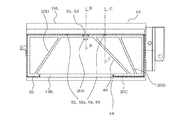
図1は、実施の形態に係る換気装置100の分解図である。図2は、図1に示す換気装置100の模式図である。図3は、実施の形態に係る換気装置100の給気風路25のうちの給気用ファン11から熱交換器5の上流側までの構成を説明する図である。図4は、図3に示すA−A断面図である。
なお、図2(a)は水平断面図であり、図2(b)は風向可変ルーバー2が垂直面に平行な状態の縦断面図であり、図2(c)は正面図であり、図2(d)は風向可変ルーバー2が水平面に平行な状態の縦断面図である。また、図2〜図4に図示された矢印は、空気の流れを表している。
本実施の形態に係る換気装置100は、本体101から空調対象空間に水が漏洩してしまうことを抑制することができる改良が加えられたものである。
Hereinafter, embodiments of the present invention will be described with reference to the drawings.
Embodiment.
FIG. 1 is an exploded view of a ventilation device 100 according to an embodiment. FIG. 2 is a schematic diagram of the ventilation device 100 shown in FIG. FIG. 3 is a diagram illustrating a configuration from the supply fan 11 to the upstream side of the heat exchanger 5 in the supply air passage 25 of the ventilation device 100 according to the embodiment. 4 is a cross-sectional view taken along line AA shown in FIG.
2A is a horizontal sectional view, FIG. 2B is a longitudinal sectional view of the state in which the wind direction variable louver 2 is parallel to the vertical plane, and FIG. 2C is a front view. 2 (d) is a longitudinal sectional view of the state in which the wind direction variable louver 2 is parallel to the horizontal plane. Moreover, the arrow shown in FIGS. 2-4 represents the flow of air.
The ventilator 100 according to the present embodiment is an improvement in which water can be prevented from leaking from the main body 101 to the air-conditioning target space.

換気装置100は、空調対象空間(たとえば、室内、ビル、倉庫など)の空気を取り込んで空調対象空間外に排出するとともに、空調対象空間外の空気を取り込んで空調対象空間に供給することができるものである。なお、本実施の形態では、空調対象空間が室内である場合を例に説明する。また、「室外空気」は換気装置100から室内に供給される「給気」に対応し、「室内空気」は、換気装置100から室外に排出される「排気」に対応している。   The ventilation device 100 can take in air in an air-conditioning target space (for example, indoors, buildings, warehouses, etc.) and discharge it outside the air-conditioning target space, and can take in air outside the air-conditioning target space and supply it to the air-conditioning target space. Is. In the present embodiment, a case where the air-conditioning target space is indoors will be described as an example. “Outdoor air” corresponds to “supply air” supplied from the ventilator 100 to the room, and “indoor air” corresponds to “exhaust air” discharged from the ventilator 100 to the outside of the room.

換気装置100は、「各種機器が搭載される本体101」と、「本体101の前面側に設けられる正面パネル1」と、「本体101の前面側であって正面パネル1の下側に取り付けられる風向可変ルーバー2」と、「本体101の背面側に接続される室外空気を取り込むための給気入口部8」と、「本体101の背面側に接続され、室内空気を排気するのに利用される排気出口部9」と、「取り込んだ室外空気と室内空気とを熱交換させる熱交換器5」と、「室外空気を本体101内に取り込む給気用ファン11」と、「室内空気を取り込む排気用ファン12」と、「取り込んだ室外空気に含まれる塵埃などを補足するフィルターユニット7」と、「室内空気に含まれる塵埃などを捕集する室内側フィルター21」とを有している。   The ventilator 100 is attached to “a main body 101 on which various devices are mounted”, “a front panel 1 provided on the front side of the main body 101”, and “a front side of the main body 101 and below the front panel 1”. “Variable air direction louver 2”, “Air supply inlet 8 for taking in outdoor air connected to the back side of the main body 101”, “Connected to the back side of the main body 101 and used to exhaust indoor air "Exhaust outlet 9", "heat exchanger 5 for exchanging heat between the taken-out outdoor air and indoor air", "air supply fan 11 for taking outdoor air into main body 101", and "take in indoor air" It has an “exhaust fan 12”, “a filter unit 7 that captures dust and the like contained in the taken-in outdoor air”, and “indoor filter 21 that collects dust and the like contained in room air”.

(本体101)
本体101は、たとえば、略直方体形状で外郭を形成するものであり、給気用ファン11、排気用ファン12、熱交換器5、フィルターユニット7、室内側フィルター21などが搭載されているものである。
本体101の前面側には、換気装置100の前面を構成する正面パネル1が設けられ、この正面パネル1の下側に風向可変ルーバー2が設けられている。
(Main unit 101)
For example, the main body 101 has a substantially rectangular parallelepiped shape and forms an outer shell. The main body 101 includes an air supply fan 11, an exhaust fan 12, a heat exchanger 5, a filter unit 7, an indoor filter 21, and the like. is there.
A front panel 1 constituting the front surface of the ventilation device 100 is provided on the front side of the main body 101, and a wind direction variable louver 2 is provided on the lower side of the front panel 1.

本体101の背面側には、室外と本体101とを連通する給気入口部8が接続されて設けられている。また、本体101の背面側には、本体101を正面視したときにおいて、給気入口部8の左側に室外と本体101とを連通する排気出口部9が接続されて設けられている。
本体101には、本体101内に供給される室外空気と室内空気とが混合しないようにする送風機取付板22が立設されている。送風機取付板22の前面側が、本体101内に供給される室内空気が流れる給気風路25の一部を構成し、送風機取付板22の背面側が、本体101内に供給される室外空気が流れる排気風路26の一部を構成している。なお、給気風路25及び排気風路26については、後ほど説明する。
On the back side of the main body 101, an air supply inlet portion 8 that connects the outdoor body and the main body 101 is connected and provided. Further, on the back side of the main body 101, when the main body 101 is viewed from the front, an exhaust outlet portion 9 that connects the outdoor and the main body 101 is connected to the left side of the air supply inlet portion 8.
The main body 101 is provided with a blower mounting plate 22 that prevents outdoor air and indoor air supplied into the main body 101 from being mixed. The front side of the blower mounting plate 22 constitutes a part of an air supply passage 25 through which indoor air supplied into the main body 101 flows, and the rear side of the blower mounting plate 22 exhausts through which outdoor air supplied into the main body 101 flows. A part of the air passage 26 is formed. The supply air passage 25 and the exhaust air passage 26 will be described later.

本体101は、本体101の前面側に位置する前ケーシング3と、この前ケーシング3の背面側に設けられる後ケーシング4と、前ケーシング3及び後ケーシング4に収容されている中ケーシング17とを有しているものである。   The main body 101 has a front casing 3 located on the front side of the main body 101, a rear casing 4 provided on the rear side of the front casing 3, and a middle casing 17 accommodated in the front casing 3 and the rear casing 4. It is what you are doing.

前ケーシング3には、正面パネル1が予め設定された間隔を空けて設けられている。そして、この間隔が空けられた部分には、熱交換器5で室内空気(排気)と熱交換した室外空気(給気)が流れる給気出口部6と、熱交換器5で室外空気と熱交換した室内空気が流れる排気入口部10とが設けられている。また、前ケーシング3には、後述する排気用ファン12の排気用羽根12Aが収容される収容部3Aが形成されている。
なお、給気出口部6は、給気風路25のうちの熱交換器5の下流側に対応する部分であり、排気入口部10は、排気風路26のうちの熱交換器5の上流側に対応する部分である。また、排気入口部10には、室内側フィルター21が配置されており、室内空気に含まれる塵埃などを捕集し、熱交換器5などが塵埃などで詰まってしまい熱交換効率が低減してしまうことが抑制されている。
前ケーシング3には、熱交換器5などから滴下する凝縮水を貯留するドレン皿16が一体的に形成されている。そして、前ケーシング3、中ケーシング17及び後ケーシング4が組み合わされた状態では、このドレン皿16の下面側が中ケーシング17の一部によって支持されている(図11参照)。なお、本実施の形態では、前ケーシング3にドレン皿16が一体的に形成されているものとして説明するがそれに限定されるものではなく、ドレン皿16を別体で設けてもよい。
The front casing 3 is provided with a front panel 1 with a predetermined interval. And in the part which this space | interval spaced apart, in the heat exchanger 5, the outdoor air (heat supply) through which the outdoor air (heated air) which heat-exchanged with the indoor air (exhaust) flows, and the outdoor air and heat in the heat exchanger 5 An exhaust inlet 10 through which the exchanged indoor air flows is provided. The front casing 3 is formed with an accommodating portion 3A for accommodating exhaust vanes 12A of an exhaust fan 12, which will be described later.
The supply air outlet portion 6 is a portion corresponding to the downstream side of the heat exchanger 5 in the supply air passage 25, and the exhaust inlet portion 10 is the upstream side of the heat exchanger 5 in the exhaust air passage 26. It is a part corresponding to. In addition, an indoor filter 21 is disposed at the exhaust inlet 10 to collect dust and the like contained in room air, and the heat exchanger 5 and the like are clogged with dust and the heat exchange efficiency is reduced. It is suppressed.
The front casing 3 is integrally formed with a drain pan 16 for storing condensed water dripped from the heat exchanger 5 or the like. When the front casing 3, the middle casing 17, and the rear casing 4 are combined, the lower surface side of the drain pan 16 is supported by a part of the middle casing 17 (see FIG. 11). In addition, in this Embodiment, although demonstrated as what the drain pan 16 is integrally formed in the front casing 3, it is not limited to it, You may provide the drain pan 16 separately.

後ケーシング4には、給気入口部8の開閉及び排気出口部9の開閉を行うシャッター13及びサブシャッター14が設けられている。シャッター13には、給気入口部8と連通する開口15が設けられている。
換気装置100の運転時などには、シャッター13及びサブシャッター14を開き、給気入口部8と開口15とが連通して給気入口部8側から開口15側に空気が流れるようになる。
また、換気装置100の停止時などには、シャッター13及びサブシャッター14を閉じ、給気入口部8及び排気出口部9が閉塞される。これにより、本体101と室外側との連通を遮断し、室外側から本体101側に空気が侵入することが抑制されるようになっている。
The rear casing 4 is provided with a shutter 13 and a sub-shutter 14 that open and close the air supply inlet 8 and the exhaust outlet 9. The shutter 13 is provided with an opening 15 that communicates with the air supply inlet 8.
When the ventilator 100 is in operation, the shutter 13 and the sub-shutter 14 are opened, the air supply inlet portion 8 and the opening 15 communicate with each other, and air flows from the air supply inlet portion 8 side to the opening 15 side.
Further, when the ventilation device 100 is stopped, the shutter 13 and the sub-shutter 14 are closed, and the air supply inlet portion 8 and the exhaust outlet portion 9 are closed. Thereby, the communication between the main body 101 and the outdoor side is blocked, and the intrusion of air from the outdoor side to the main body 101 side is suppressed.

中ケーシング17は、ドレン皿16、熱交換器5、及びフィルターユニット7などを支持するように、前ケーシング3及び後ケーシング4に収容されているものである。中ケーシング17は、たとえば箱状にスチロール成型されて得られる。また、中ケーシング17には、後述する給気用ファン11の給気用羽根11Aが収容される収容部17Aが形成されている。
中ケーシング17の詳細構成については、後段の図11及び図12で説明する。
The middle casing 17 is accommodated in the front casing 3 and the rear casing 4 so as to support the drain pan 16, the heat exchanger 5, the filter unit 7, and the like. The inner casing 17 is obtained, for example, by styrene molding in a box shape. Further, the middle casing 17 is formed with an accommodating portion 17A for accommodating an air supply blade 11A of an air supply fan 11 described later.
The detailed configuration of the inner casing 17 will be described with reference to FIGS.

(正面パネル1及び風向可変ルーバー2)
正面パネル1は、本体101の前ケーシング3の前側に設けられ、換気装置100の前面の一部を構成するものである。正面パネル1は、正面視したときの平面形状が略長方形形状をした平板部材である。正面パネル1は、本体101が室内に設置された状態において、鉛直方向に平行に設けられる。また、正面パネル1の下端側には、風向可変ルーバー2が回転自在に設けられている。正面パネル1には、正面パネル1の背面側と本体101の前ケーシング3との間に給気出口部6及び排気入口部10が設けられている。
風向可変ルーバー2は、給気出口部6から室内側に吹き出される空気の方向を変化させることが可能なものである。すなわち、風向可変ルーバー2は、本体101側から噴出される空気の方向を、図2(b)に示すように鉛直方向、或いは、図2(d)に示すように水平方向に変化させることができるものである。
風向可変ルーバー2は、本体101の前面側であって正面パネル1の下側に回転可能に設けられている。風向可変ルーバー2は、正面視したときの平面形状が、たとえば略長方形形状をした平板部材である。
(Front panel 1 and wind direction variable louver 2)
The front panel 1 is provided on the front side of the front casing 3 of the main body 101 and constitutes a part of the front surface of the ventilation device 100. The front panel 1 is a flat plate member having a substantially rectangular shape when viewed from the front. The front panel 1 is provided in parallel to the vertical direction in a state where the main body 101 is installed indoors. A wind direction variable louver 2 is rotatably provided on the lower end side of the front panel 1. The front panel 1 is provided with an air supply outlet 6 and an exhaust inlet 10 between the back side of the front panel 1 and the front casing 3 of the main body 101.
The air direction variable louver 2 can change the direction of the air blown out from the air supply outlet portion 6 to the indoor side. That is, the wind direction variable louver 2 can change the direction of the air ejected from the main body 101 side in the vertical direction as shown in FIG. 2B or in the horizontal direction as shown in FIG. It can be done.
The wind direction variable louver 2 is rotatably provided on the front side of the main body 101 and below the front panel 1. The wind direction variable louver 2 is a flat plate member having a substantially rectangular shape when viewed from the front.

(給気入口部8及び排気出口部9)
給気入口部8は、たとえば、室内と室外とを隔てる家屋の壁などに形成されている開口部に接続されるものである。すなわち、給気入口部8は、本体101と室外とを連通させるものである。給気入口部8は、一端側が本体101の後ケーシング4に接続され、他方側が室外側に設けられている。なお、たとえば風雨などが強い状況においては、シャッター13及びサブシャッター14などが閉じられて、給気入口部8側から本体101内に水が浸入してしまうことが抑制されるようになっている。
排気出口部9も、たとえば、室内と室外とを隔てる家屋の壁などに形成されている開口部に接続されるものである。すなわち、排気出口部9は、本体101と室外とを連通させるものである。排気出口部9は、一端側が本体101の後ケーシング4に接続され、他端側が室外側に設けられている。
(Air supply inlet 8 and exhaust outlet 9)
The air supply inlet 8 is connected to, for example, an opening formed in a wall of a house that separates the room from the outside. In other words, the air supply inlet 8 communicates the main body 101 with the outside. One end side of the air supply inlet portion 8 is connected to the rear casing 4 of the main body 101, and the other side is provided on the outdoor side. For example, in a situation where wind and rain are strong, the shutter 13 and the sub-shutter 14 are closed to prevent water from entering the main body 101 from the supply air inlet 8 side. .
The exhaust outlet portion 9 is also connected to, for example, an opening formed in a wall of a house that separates the room from the outside. In other words, the exhaust outlet 9 communicates the main body 101 with the outdoor. One end side of the exhaust outlet 9 is connected to the rear casing 4 of the main body 101, and the other end side is provided on the outdoor side.

(熱交換器5)
熱交換器5は、本体101に取り込んだ室外空気と、本体101内に取り込んだ室内空気とを熱交換させるものである。すなわち、熱交換器5は、排気の熱量を給気で回収する機能を有しているものである。熱交換器5は、換気装置100を正面視したときに、給気用ファン11及び排気用ファン12の左側に配置されている。
なお、熱交換器5は、熱交換器5に流入した室外空気と、室内空気とは混合しないように構成されている。すなわち、熱交換器5は、室外空気が流れる第1流路と、室内空気が流れる第2流路とが隔てられており、複数のフィンが積層されて構成されている。そして、第1流路と第2流路とは、熱交換器5内で交差し、また、熱交換できるようにフィンを介して隔てられている。なお、フィンの積層方向は、熱交換器5の長手方向に対応している。
また、熱交換器5には、熱交換器5の側面のうち室外空気が流出する側の側面に、熱交換器5を支持するのに利用される熱交換器取手24が設けられている。
(Heat exchanger 5)
The heat exchanger 5 exchanges heat between outdoor air taken into the main body 101 and indoor air taken into the main body 101. That is, the heat exchanger 5 has a function of recovering the heat quantity of the exhaust gas with the supply air. The heat exchanger 5 is disposed on the left side of the air supply fan 11 and the exhaust fan 12 when the ventilator 100 is viewed from the front.
The heat exchanger 5 is configured not to mix outdoor air flowing into the heat exchanger 5 and indoor air. That is, the heat exchanger 5 is configured such that a first flow path through which outdoor air flows and a second flow path through which indoor air flow are separated, and a plurality of fins are stacked. And the 1st channel and the 2nd channel intersect in heat exchanger 5, and are separated via a fin so that heat exchange is possible. The fin stacking direction corresponds to the longitudinal direction of the heat exchanger 5.
Further, the heat exchanger 5 is provided with a heat exchanger handle 24 used to support the heat exchanger 5 on the side surface of the heat exchanger 5 on the side from which outdoor air flows out.

ここで、図4に示すように、「熱交換器5の側面のうちの給気用羽根11A側の側面33の上端となる端部33aと、側面33の下端となる端部とを結ぶ対角線(ウ)」と、「熱交換器5の側面33の後端となる端部33bと、側面33の前端となる端部とを結ぶ対角線(エ)」との交点を交点39と称する。
仮にフィルターユニット7が設けられていない場合においては、側面33のうちの交点39と端部33aと端部33bとを結んで形成される三角形の面29は、給気風路25を流れる給気と接触する面となる。そして、この面29は、給気の流れ方向に対して垂直となっている。
このため、仮にフィルターユニット7が設けられていないと、本体101内に取り入れられた室外空気が、この面29に衝突して面29で結露が生じてしまう。そして、この結露した水は、熱交換器5の側面33を伝ってドレン皿16が設けられていない部分に滴下し、本体101から室内に水が漏洩してしまう可能性がある。
そこで、本実施の形態に係る換気装置100は、給気風路25内の水が室内に漏洩しないように、フィルターユニット7が構成されている。
Here, as shown in FIG. 4, “a diagonal line connecting an end portion 33 a that is the upper end of the side surface 33 on the air supply blade 11 </ b> A side of the side surface of the heat exchanger 5 and an end portion that is the lower end of the side surface 33. The point of intersection of “(c)” and “diagonal line (d) connecting the end portion 33 b serving as the rear end of the side surface 33 of the heat exchanger 5 and the end portion serving as the front end of the side surface 33” is referred to as an intersection point 39.
If the filter unit 7 is not provided, the triangular surface 29 formed by connecting the intersection 39 of the side surface 33 with the end portion 33a and the end portion 33b is connected to the supply air flowing through the supply air passage 25. It becomes the contact surface. The surface 29 is perpendicular to the flow direction of the air supply.
For this reason, if the filter unit 7 is not provided, outdoor air taken into the main body 101 collides with the surface 29 and condensation occurs on the surface 29. And this condensed water drops along the side 33 of the heat exchanger 5 to a portion where the drain pan 16 is not provided, and there is a possibility that the water leaks from the main body 101 into the room.
Therefore, in the ventilator 100 according to the present embodiment, the filter unit 7 is configured so that water in the supply air passage 25 does not leak into the room.

(給気用ファン11及び排気用ファン12)
給気用ファン11は、回転する給気用羽根11A、給気用羽根11Aを回転させる送風用電動機23により構成され、送風用電動機23の回転を図示省略のシャフトにより給気用羽根11Aに伝えて給気用羽根11Aを回転させるものである。これにより、本体101に室外空気を取り込み、放出することができる。
排気用ファン12は、回転する排気用羽根12A、排気用羽根12Aを回転させる送風用電動機23により構成され、送風用電動機23の回転を図示省略のシャフトにより排気用羽根12Aに伝えて排気用羽根12Aを回転させるものである。これにより、本体101に室内空気を取り込み、放出することができる。
(Air supply fan 11 and exhaust fan 12)
The air supply fan 11 includes a rotating air supply blade 11A and an air supply motor 23 that rotates the air supply blade 11A. The rotation of the air supply motor 23 is transmitted to the air supply blade 11A through a shaft (not shown). Thus, the air supply blade 11A is rotated. As a result, outdoor air can be taken into and released from the main body 101.
The exhaust fan 12 includes a rotating exhaust blade 12A and a blower motor 23 that rotates the exhaust blade 12A. The rotation of the blower motor 23 is transmitted to the exhaust blade 12A through a shaft (not shown) to be exhausted. 12A is rotated. Thereby, the indoor air can be taken into and released from the main body 101.

給気用ファン11及び排気用ファン12は、たとえばシロッコファンなどで構成するとよい。なお、送風用電動機23は、図1に示すように、送風機取付板22を境にして、給気が流れる風路側と排気が流れる風路側に跨がって設けられている。   The air supply fan 11 and the exhaust fan 12 may be composed of, for example, a sirocco fan. As shown in FIG. 1, the blower motor 23 is provided across the air passage side through which the supply air flows and the air passage side through which the exhaust flows, with the blower mounting plate 22 as a boundary.

(フィルターユニット7)
フィルターユニット7は、図1に示すように、給気風路25のうちの熱交換器5の上流側に設けられ、虫、塵埃などを捕集するフィルター18と、固定側ケース19及び取外側ケース20とを有している。
フィルター18は、固定側ケース19と取外側ケース20との間に収容されているものである。そして、フィルター18は、たとえば、熱交換器5の給気の流入口の形状に対応するように、平面視形状が四角形状に形成されている。フィルター18が設けられていることにより、室内に虫、塵埃などが除かれた空気を供給することができるとともに、熱交換器5に虫、塵埃などが入って熱交換器5の流路が詰まってしまい、熱交換効率が低減してしまうことを抑制することができる。
固定側ケース19は、熱交換器5のうちの給気用ファン11側の側面に接触するように設けられる壁部19F、本体101内に取り入れられた室外空気が壁部19F側に送り込まれて発生した水を受ける水受け部19A、及び、給気風路25と排気風路26とを仕切る第2の風路仕切部19Lなどが形成されたものである。固定側ケース19は、中ケーシング17に接続されて支持されている。
取外側ケース20は、フィルターユニット7が本体101に取り付けられた状態において、固定側ケース19と熱交換器5との間に設けられるものである。取外側ケース20は、固定側ケース19に接続されて固定されている。
フィルターユニット7の詳細構成については、後段の図11及び図12で説明する。
(Filter unit 7)
As shown in FIG. 1, the filter unit 7 is provided on the upstream side of the heat exchanger 5 in the supply air passage 25, and includes a filter 18 that collects insects, dust, and the like, a fixed case 19, and an outer case. 20.
The filter 18 is accommodated between the fixed case 19 and the outer case 20. The filter 18 has a quadrangular shape in plan view so as to correspond to, for example, the shape of the air supply inlet of the heat exchanger 5. By providing the filter 18, air from which insects and dust are removed can be supplied into the room, and insects and dust enter the heat exchanger 5 to block the flow path of the heat exchanger 5. Therefore, it can suppress that heat exchange efficiency falls.
The stationary side case 19 is provided with a wall 19F provided so as to be in contact with a side surface of the heat exchanger 5 on the side of the air supply fan 11, and outdoor air taken into the main body 101 is sent to the wall 19F. A water receiving portion 19A that receives the generated water, a second air passage partition portion 19L that partitions the supply air passage 25 and the exhaust air passage 26, and the like are formed. The stationary case 19 is connected to and supported by the inner casing 17.
The outer case 20 is provided between the fixed case 19 and the heat exchanger 5 in a state where the filter unit 7 is attached to the main body 101. The outer case 20 is connected to and fixed to the fixed case 19.
The detailed configuration of the filter unit 7 will be described later with reference to FIGS. 11 and 12.

(室内側フィルター21)
室内側フィルター21は、排気入口部10に設けられ、室内空気に含まれる塵埃などを捕集するものである。室内側フィルター21によって室内空気が清浄されるとともに、熱交換器5に塵埃などが入ってしまうことを抑制し、熱交換器5の熱交換効率が低減してしまうことを抑制することができるものである。
(Indoor filter 21)
The indoor filter 21 is provided at the exhaust inlet 10 and collects dust contained in the indoor air. The room-side filter 21 can clean indoor air, suppress dust from entering the heat exchanger 5, and reduce heat exchange efficiency of the heat exchanger 5. It is.

[空気の流れの説明]
換気装置100には、室外空気が流れる給気風路25と、室内空気が流れる排気風路26とが形成されている。
給気風路25は、空気流れ方向の上流側から、給気入口部8、後ケーシング4、給気用羽根11A、フィルターユニット7、熱交換器5、及び給気出口部6が連通して形成された風路である。
給気a(室外空気)は、給気入口部8を介して本体101内に取り込まれる。この本体101内に取り込まれた給気aは、給気用ファン11を通って熱交換器5に流入する。そして、この熱交換器5に流入した給気aは、熱交換器5に流入した排気bと熱交換した後に、熱交換器5から放出される。そして、熱交換器5から放出された給気aは、給気出口部6を介して室内に放出される。なお、この室内に放出される給気aは、風向可変ルーバー2の作用によって鉛直方向(図2(b)参照)或いは水平方向(図2(d)参照)に風向が調整される。
[Explanation of air flow]
The ventilation device 100 is formed with an air supply passage 25 through which outdoor air flows and an exhaust air passage 26 through which room air flows.
The air supply air passage 25 is formed from the upstream side in the air flow direction by connecting the air supply inlet portion 8, the rear casing 4, the air supply blade 11A, the filter unit 7, the heat exchanger 5, and the air supply outlet portion 6. It was a wind path.
The supply air a (outdoor air) is taken into the main body 101 through the supply air inlet 8. The supply air a taken into the main body 101 flows into the heat exchanger 5 through the supply fan 11. The supply air a flowing into the heat exchanger 5 is discharged from the heat exchanger 5 after exchanging heat with the exhaust b flowing into the heat exchanger 5. Then, the supply air “a” released from the heat exchanger 5 is released into the room through the supply outlet 6. The air supply a discharged into the room is adjusted in the wind direction in the vertical direction (see FIG. 2B) or in the horizontal direction (see FIG. 2D) by the action of the wind direction variable louver 2.

排気風路26は、空気流れ方向の上流側から、排気入口部10、室内側フィルター21、排気用羽根12A、熱交換器5、後ケーシング4、及び排気出口部9が連通して形成された風路である。
排気b(室内空気)は、排気入口部10から本体101内に取り込まれる。この本体101内に取り込まれた排気bは、室内側フィルター21を通って塵埃などが捕集されたのちに、排気用ファン12を通って熱交換器5に流入する。この熱交換器5に流入した排気bは、熱交換器5に流入した給気aと熱交換した後に、熱交換器5から放出される。そして、熱交換器5から放出された排気bは、排気出口部9を介して室外に放出される。
The exhaust air passage 26 is formed from the upstream side in the air flow direction, and the exhaust inlet 10, the indoor filter 21, the exhaust blade 12 </ b> A, the heat exchanger 5, the rear casing 4, and the exhaust outlet 9 are connected. It is an airway.
Exhaust b (room air) is taken into the main body 101 from the exhaust inlet 10. The exhaust b taken into the main body 101 flows into the heat exchanger 5 through the exhaust fan 12 after dust and the like are collected through the indoor filter 21. The exhaust b flowing into the heat exchanger 5 is discharged from the heat exchanger 5 after exchanging heat with the supply air a flowing into the heat exchanger 5. Then, the exhaust b discharged from the heat exchanger 5 is discharged outside through the exhaust outlet 9.

[フィルターユニット7の詳細説明]
図5は、実施の形態に係る換気装置100の熱交換器5及びフィルターユニット7の斜視図である。図6は、図5に示す熱交換器5及びフィルターユニット7が本体101に取り付けられた状態における縦断面図である。図7は、図5及び図6に示すフィルターユニット7の分解図である。図5〜図7を参照してフィルターユニット7の詳細な構成について説明する。
[Detailed description of filter unit 7]
FIG. 5 is a perspective view of the heat exchanger 5 and the filter unit 7 of the ventilation device 100 according to the embodiment. FIG. 6 is a vertical cross-sectional view of the heat exchanger 5 and the filter unit 7 shown in FIG. FIG. 7 is an exploded view of the filter unit 7 shown in FIGS. 5 and 6. A detailed configuration of the filter unit 7 will be described with reference to FIGS.

[固定側ケース19]
固定側ケース19は、「給気風路25のうちの熱交換器5の上流側の一部を構成する熱交換器5の側面側に設けられ、水を貯留する水受け部19A」と、「熱交換器5の長手方向に伸びるように形成されたフィルター収納部19B」と、「フィルター収納部19Bに形成され、水受け部19A側に接続された水路用リブ19C」とを有している。
また、固定側ケース19は、「水受け部19Aのうちの正面パネル1側の端部側に形成された第1の風路仕切部19D」と、「第1の風路仕切部19Dの上端側から熱交換器5の長手方向に伸びるように形成されている第2の風路仕切部19Lを有する上部19E」と、「水受け部19Aのうちの熱交換器5側の端部側に形成された壁部19F」と、「第2の風路仕切部19Lに接触するように設けられる断熱材19G(図12参照)」と、「水受け部19Aと上部19Eとを接続するように形成されている接続リブ19H」とを有している。
固定側ケース19は、たとえば樹脂で構成されたものであり、水受け部19A、フィルター収納部19B、水路用リブ19C、第1の風路仕切部19D、上部19E、壁部19F及び接続リブ19Hが一体形成されたものである。
[Fixed side case 19]
The stationary case 19 is provided on the side surface side of the heat exchanger 5 that constitutes a part of the air supply air passage 25 on the upstream side of the heat exchanger 5 and stores water, and “ A filter housing portion 19B formed so as to extend in the longitudinal direction of the heat exchanger 5, and a “water channel rib 19C formed in the filter housing portion 19B and connected to the water receiving portion 19A”. .
The fixed side case 19 includes “a first air passage partition portion 19D formed on the end portion of the water receiving portion 19A on the front panel 1 side” and “an upper end of the first air passage partition portion 19D. "The upper part 19E having the second air passage partition part 19L formed so as to extend in the longitudinal direction of the heat exchanger 5 from the side" and "on the end part side of the heat exchanger 5 side of the water receiving part 19A" “The formed wall portion 19F”, “the heat insulating material 19G (see FIG. 12) provided so as to contact the second air passage partition portion 19L”, and “the water receiving portion 19A and the upper portion 19E are connected to each other”. The connecting rib 19H "is formed.
The stationary case 19 is made of, for example, resin, and includes a water receiving portion 19A, a filter storage portion 19B, a water channel rib 19C, a first air channel partitioning portion 19D, an upper portion 19E, a wall portion 19F, and a connection rib 19H. Are integrally formed.

(水受け部19A)
水受け部19Aは、たとえば、本体101内に取り入れられた室外空気とともに流れてくる霧状の水、及び、室外空気が給気風路25で結露することで生じる水などを貯留するものである。この水受け部19Aはフィルターユニット7に一体的に組み込まれたもの、すなわち、水受け部19Aは、固定側ケース19に一体形成されたもの、として説明するがそれに限定されるものではなく、別体でもよい。
水受け部19Aは、フィルターユニット7が本体101に取り付けられた状態において、たとえば、水平面と平行となるように形成されたものである。なお、水受け部19Aは、本体101にフィルターユニット7が取り付けられた状態において、上面が水平面と平行であってもよいし、水を貯留しやすいように凹状に形成されていてもよいし、或いは、水路用リブ19C側に水が流れやすくするように水路用リブ19Cに対して下側に傾斜する傾斜面が形成されていてもよい。
(Water receiving part 19A)
19 A of water receptacles store the mist-like water which flows with the outdoor air taken in in the main body 101, the water which arises when outdoor air condenses in the supply air path 25, etc., for example. The water receiving portion 19A is described as being integrally incorporated in the filter unit 7, that is, the water receiving portion 19A is integrally formed with the fixed side case 19, but is not limited thereto. It may be the body.
The water receiving portion 19A is formed, for example, so as to be parallel to the horizontal plane in a state where the filter unit 7 is attached to the main body 101. The water receiver 19A may have a top surface that is parallel to a horizontal plane in a state where the filter unit 7 is attached to the main body 101, or may be formed in a concave shape so as to easily store water. Or the inclined surface which inclines below with respect to the rib 19C for waterways may be formed so that water may flow easily to the rib 19C for waterways.

水受け部19Aは、熱交換器5側の端部側に壁部19Fが連続的に接続されている。このため、水受け部19A及び壁部19Fは、水受け部19A及び壁部19Fが通る縦断面で見たとき、L字状になっている。
また、水受け部19Aは、正面パネル1側の端部側に第1の風路仕切部19Dが連続的に接続されている。このため、水受け部19A及び第1の風路仕切部19Dは、水受け部19A及び第1の風路仕切部19Dが通る縦断面で見たときにもL字状となっている。
これにより、水受け部19Aは、本体101内に取り込まれた霧状の水や水蒸気を含む空気が、壁部19F及び第1の風路仕切部19Dで結露し、流れ落ちてきた水を貯留することができる。また、水受け部19Aは、壁部19F及び第1の風路仕切部19Dに対して連続的に接続されており、部材間の隙間がないため、ドレン皿16が設置されていない箇所に水が流れていき、室内側に水が漏洩してしまうことを抑制することができる。
In the water receiving portion 19A, a wall portion 19F is continuously connected to the end portion side on the heat exchanger 5 side. For this reason, the water receiving part 19A and the wall part 19F are L-shaped when viewed in a longitudinal section through which the water receiving part 19A and the wall part 19F pass.
Moreover, 19 A of water receptacle parts are connected to the 1st air-path partition part 19D continuously by the edge part side by the side of the front panel 1. FIG. For this reason, the water receiving part 19A and the first air path partitioning part 19D are also L-shaped when viewed in a longitudinal section through which the water receiving part 19A and the first air path partitioning part 19D pass.
Thereby, 19 A of water receptacle parts store the water which the water containing the mist-like water taken in in the main body 101 and the water vapor | steam condensed at the wall part 19F and the 1st air-path partition part 19D, and flowed down. be able to. Further, since the water receiving portion 19A is continuously connected to the wall portion 19F and the first air passage partitioning portion 19D and there is no gap between the members, the water receiving portion 19A has water in a place where the drain pan 16 is not installed. Can flow and water can be prevented from leaking into the room.

なお、水受け部19Aには、水受け部19Aのうちの後ケーシング4側の端部側に傾斜部19Iが形成されている。傾斜部19Iには、フィルターユニット7が本体101に取り付けられた状態において、後ケーシング4側から正面パネル1側に向かって下側に傾斜した傾斜面が形成されている。これにより、水受け部19Aに貯留された水が、水路用リブ19C側に導かれるようになっている。   In addition, in the water receiving portion 19A, an inclined portion 19I is formed on the end portion of the water receiving portion 19A on the rear casing 4 side. The inclined portion 19I is formed with an inclined surface inclined downward from the rear casing 4 side toward the front panel 1 side when the filter unit 7 is attached to the main body 101. Thereby, the water stored in the water receiving part 19A is guided to the water channel rib 19C side.

また、固定側ケース19に壁部19Fが形成されていなくてもよい。この場合には、水受け部19Aの熱交換器5側と熱交換器5の側面とが密着するように取り付けることで、水受け部19Aと熱交換器5との隙間から結露が漏れてしまうことを防止することができる。   Further, the wall portion 19 </ b> F may not be formed in the fixed side case 19. In this case, condensation is leaked from the gap between the water receiver 19A and the heat exchanger 5 by attaching the water receiver 19A so that the heat exchanger 5 side and the side surface of the heat exchanger 5 are in close contact with each other. This can be prevented.

(フィルター収納部19B)
フィルター収納部19Bは、後述する取外側ケース20の下部20Aの下面と対向するように設けられ、取外側ケース20を支持するものである。フィルター収納部19Bは、熱交換器5のフィンの積層方向と平行、すなわち、熱交換器5の長手方向と平行に伸びるように形成されたものである。なお、フィルター収納部19Bには、水路用リブ19Cが接続されている。
(Filter storage part 19B)
The filter storage portion 19B is provided so as to face the lower surface of the lower portion 20A of the outside case 20 described later, and supports the outside case 20. The filter storage portion 19 </ b> B is formed to extend in parallel with the fin stacking direction of the heat exchanger 5, that is, in parallel with the longitudinal direction of the heat exchanger 5. A water channel rib 19C is connected to the filter housing portion 19B.

フィルター収納部19Bは、水平方向における水受け部19A側の端部側に形成され、水路用リブ19Cに接続する水抜き通路19Jが形成されている。フィルター収納部19Bは、この水抜き通路19Jの形成位置でフィルター18の下端側とは接触していない。
たとえば、フィルター収納部19Bは、水抜き通路19Jの形成位置が、凹状になっている。すなわち、フィルター収納部19Bは、水抜き通路19Jの形成面と、フィルター18の下面との間に予め設定された間隔の隙間が形成されているということである。これにより、水路用リブ19C側から流れてきた水が、フィルター収納部19Bに流れ込んでくるようになっている。
また、フィルター収納部19Bには、前後方向における正面パネル1側の端部側に、立設するように形成された支持部19Kが設けられている。この支持部19Kは、取外側ケース20が固定側ケース19から離脱してしまうことがないように、取外側ケース20を支持する機能を有している。
さらに、フィルター収納部19Bの下面側は、フィルターユニット7が本体101に取り付けられた状態において中ケーシング17に支持されるようになっている(図11参照)。
The filter storage portion 19B is formed on the end side on the water receiving portion 19A side in the horizontal direction, and a drain passage 19J connected to the water channel rib 19C is formed. The filter storage portion 19B is not in contact with the lower end side of the filter 18 at the position where the drain passage 19J is formed.
For example, in the filter storage part 19B, the formation position of the drain passage 19J is concave. That is, in the filter storage portion 19B, a gap having a preset interval is formed between the formation surface of the drain passage 19J and the lower surface of the filter 18. Thereby, the water that flows from the side of the water channel rib 19C flows into the filter storage portion 19B.
The filter storage portion 19B is provided with a support portion 19K formed so as to stand upright on the end portion side on the front panel 1 side in the front-rear direction. The support portion 19 </ b> K has a function of supporting the outer case 20 so that the outer case 20 is not detached from the stationary case 19.
Further, the lower surface side of the filter storage portion 19B is supported by the middle casing 17 in a state where the filter unit 7 is attached to the main body 101 (see FIG. 11).

(水路用リブ19C)
水路用リブ19Cは、フィルター収納部19Bの前後方向における後ケーシング4側の端部側であって、フィルター収納部19Bの水平方向における水受け部19A側の端部側に形成されたものである。この水路用リブ19Cは、後ケーシング4側に突出するように形成されている。水路用リブ19Cは、水受け部19A及び水抜き通路19Jに接続されており、水受け部19A側から流れてきた水を水抜き通路19J側に流すことができる。
(River rib 19C)
The channel ribs 19C are formed on the end side on the rear casing 4 side in the front-rear direction of the filter storage portion 19B and on the end side on the water receiving portion 19A side in the horizontal direction of the filter storage portion 19B. . The water channel rib 19C is formed so as to protrude to the rear casing 4 side. The water channel rib 19C is connected to the water receiving portion 19A and the water drainage passage 19J, and can flow the water flowing from the water receiving portion 19A side to the water drainage passage 19J.

(第1の風路仕切部19D)
第1の風路仕切部19Dは、排気風路26のうちの熱交換器5の上流側と、給気風路25のうちの熱交換器5の上流側とを隔離し、給気と排気とが混合することを防止するものである。
第1の風路仕切部19Dは、水受け部19Aの正面パネル1側の端部側に連続的に接続されている。なお、本実施の形態では、第1の風路仕切部19Dと水受け部19Aとは直交するように接続されているものとして説明するが、給気と排気とが混合することを防止することができれば直交からずれていてもよい。
(First airway partition 19D)
The first air passage partition 19D isolates the upstream side of the heat exchanger 5 in the exhaust air passage 26 from the upstream side of the heat exchanger 5 in the air supply air passage 25, and supplies the air and the exhaust. Prevents mixing.
The first air passage partition portion 19D is continuously connected to the end portion side of the water receiving portion 19A on the front panel 1 side. In the present embodiment, the first air passage partition portion 19D and the water receiving portion 19A are described as being connected so as to be orthogonal to each other, but mixing of the air supply and the exhaust is prevented. If possible, it may deviate from orthogonal.

(上部19E)
上部19Eは、一端側が第1の風路仕切部19Dの上端側に接続され、この接続位置から熱交換器5の長手方向に伸びるように形成されたものである。そして、上部19Eは、下端側に接続リブ19Hが接続されており、上端側に給気と排気との混合を防止する第2の風路仕切部19Lが形成されている。
第2の風路仕切部19Lは、第1の風路仕切部19Dと同様に、排気風路26のうちの熱交換器5の上流側と、給気風路25のうちの熱交換器5の上流側とを隔離し、給気と排気とが混合することを防止するものである。
第2の風路仕切部19Lは、一端側が第1の風路仕切部19Dの上端側に接続され、この接続位置から熱交換器5の長手方向に伸びるように形成されたものである。この第2の風路仕切部19Lは、フィルター収納部19Bと平行に形成されている。
なお、第2の風路仕切部19Lは、中ケーシング17と前ケーシング3により挟まれることで、支持されている。
すなわち、フィルターユニット7の上端側は、第2の風路仕切部19Lが中ケーシング17と前ケーシング3とに挟まれて支持され、フィルターユニット7の下端側は、フィルター収納部19Bが中ケーシング17に支持されて本体101内に支持されている(図11及び図12参照)。
(Upper part 19E)
The upper portion 19E is formed so that one end side is connected to the upper end side of the first air passage partition portion 19D and extends from the connection position in the longitudinal direction of the heat exchanger 5. And the connection rib 19H is connected to the lower end side of the upper part 19E, and the 2nd wind path partition part 19L which prevents mixing with supply air and exhaust_gas | exhaustion is formed in the upper end side.
Similarly to the first air passage partition portion 19D, the second air passage partition portion 19L is provided on the upstream side of the heat exchanger 5 in the exhaust air passage 26 and on the heat exchanger 5 in the supply air passage 25. It isolates the upstream side and prevents the supply air and exhaust from mixing.
The second air passage partition portion 19L is formed so that one end side is connected to the upper end side of the first air passage partition portion 19D and extends from the connection position in the longitudinal direction of the heat exchanger 5. The second air passage partition portion 19L is formed in parallel with the filter storage portion 19B.
The second air passage partition portion 19L is supported by being sandwiched between the middle casing 17 and the front casing 3.
That is, the upper end side of the filter unit 7 is supported by the second air passage partitioning portion 19L sandwiched between the middle casing 17 and the front casing 3, and the lower end side of the filter unit 7 is supported by the filter housing portion 19B of the middle casing 17. And is supported in the main body 101 (see FIGS. 11 and 12).

このように、フィルターユニット7は、第1の風路仕切部19D及び第2の風路仕切部19Lを有するため、隣接する給気風路25と排気風路26とを隔離し、給気風路25の気密性及び排気風路26の気密性を保つことができるようになっている。これにより、換気装置100の給気風量、及び排気風量の低下を防止することができる。   Thus, since the filter unit 7 has the first air passage partition portion 19D and the second air passage partition portion 19L, the adjacent supply air passage 25 and the exhaust air passage 26 are isolated, and the supply air passage 25 is isolated. And the air tightness of the exhaust air passage 26 can be maintained. Thereby, the fall of the supply air volume of the ventilation apparatus 100 and the exhaust air volume can be prevented.

(壁部19F)
壁部19Fは、給気風路25のうちの熱交換器5の上流側の一部を構成する熱交換器5の面29と対向するように、水受け部19Aのうちの熱交換器5側の端部側から立設しているものである。壁部19Fは、先述の図4で説明したように熱交換器5の面29で結露が生じないように、面29を覆うように形成されている。
(Wall 19F)
The wall portion 19F is on the heat exchanger 5 side of the water receiving portion 19A so as to face the surface 29 of the heat exchanger 5 constituting a part of the air supply air passage 25 on the upstream side of the heat exchanger 5. It is erected from the end side. As described with reference to FIG. 4, the wall portion 19 </ b> F is formed so as to cover the surface 29 so that condensation does not occur on the surface 29 of the heat exchanger 5.

ここで、図5及び図6に示すように、フィルターユニット7が設置された状態において、フィルターユニット7に給気が衝突する部分は次の通りである。
第1の風路仕切部19Dを通る直線(カ)と、水受け部19Aの上面を通る直線(キ)との交点を交点39aと称する。
直線(カ)と熱交換器5の側面33を構成する四角形の辺との交点を上から、点33c、点33dと称する。
直線(キ)と熱交換器5の側面33を構成する四角形の辺との交点を後側から、点33e、点33fと称する。
壁部19Fは、少なくとも、「(1)交点39a」と「(2)点33c」と「(3)点33e」とで形成される三角形を覆うように形成されているとよい。ただし、壁部19Fは、これに限定されるものではない。図5及び図6に示すように、「(2)点33c」の位置を高くし、「(3)点33e」の位置を後ろ側にして、壁部19Fの三角形を広くとってもよい。
Here, as shown in FIGS. 5 and 6, the portion where the supply air collides with the filter unit 7 in the state where the filter unit 7 is installed is as follows.
An intersection of a straight line (F) passing through the first air passage partitioning part 19D and a straight line (G) passing through the upper surface of the water receiving part 19A is referred to as an intersection 39a.
From the top, the intersections of the straight line (f) and the rectangular sides constituting the side surface 33 of the heat exchanger 5 are referred to as points 33c and 33d.
The intersections between the straight line (ki) and the square sides constituting the side surface 33 of the heat exchanger 5 are referred to as points 33e and 33f from the rear side.
The wall portion 19F may be formed so as to cover at least a triangle formed by “(1) intersection 39a”, “(2) point 33c”, and “(3) point 33e”. However, the wall 19F is not limited to this. As shown in FIGS. 5 and 6, the triangle of the wall portion 19F may be widened by increasing the position of “(2) point 33c” and setting the position of “(3) point 33e” to the rear side.

(断熱材19G)
断熱材19Gは、第2の風路仕切部19Lに接触して設けられているものである(図12参照)。ここで、第2の風路仕切部19Lの一方側の面は、排気風路26に面しており、他方側の面は給気風路25に面している。特に冬場においては、排気風路26には暖かく湿度の高い空気が流れ、給気風路25には冷たい乾燥した空気が流れることから、第2の風路仕切部19Lで結露が生じやすくなる。
そこで、第2の風路仕切部19Lの一方側の面及び他方側の面に断熱材19Gを設けることで、結露を抑制することができる。なお、断熱材19Gは、予め設定された厚みを有しており、第2の風路仕切部19Lと、中ケーシング17及び前ケーシング3との間の気密性を確保する効果も得ることができる。
断熱材19Gは、たとえば、第2の風路仕切部19Lに糊などで張り付けることで固定するとよい。
(Insulation material 19G)
The heat insulating material 19G is provided in contact with the second air passage partition portion 19L (see FIG. 12). Here, one surface of the second air passage partition portion 19 </ b> L faces the exhaust air passage 26, and the other surface faces the air supply air passage 25. Particularly in winter, since warm and high-humidity air flows through the exhaust air passage 26 and cold and dry air flows through the air supply air passage 25, condensation tends to occur in the second air passage partition portion 19L.
Therefore, by providing the heat insulating material 19G on the one side surface and the other side surface of the second air passage partition portion 19L, dew condensation can be suppressed. The heat insulating material 19G has a preset thickness, and an effect of ensuring the airtightness between the second air passage partition portion 19L and the middle casing 17 and the front casing 3 can also be obtained. .
The heat insulating material 19G may be fixed, for example, by pasting it on the second air passage partitioning portion 19L with glue or the like.

(接続リブ19H)
接続リブ19Hは、固定側ケース19の矩形形状を保持する補強部材である。また、接続リブ19Hは、フィルター18の対向するように形成されており、フィルター18を支持することもできるようになっている。
接続リブ19Hは、図7に示すように、水路用リブ19Cと、上部19Eの下端側とを接続するように形成されたもののほかに、フィルター収納部19Bのうちの水受け部19Aが形成された側とは反対側の端部側から突出するように形成されたリブ19Mと、上部19Eの下端側とを接続するように形成されたものがある。このように、複数の接続リブ19Hが固定側ケース19に設けられ、固定側ケース19の変形を抑制している。
(Connection rib 19H)
The connection rib 19 </ b> H is a reinforcing member that holds the rectangular shape of the stationary case 19. Further, the connecting rib 19H is formed so as to face the filter 18, and can also support the filter 18.
As shown in FIG. 7, the connection rib 19H is formed so as to connect the water channel rib 19C and the lower end side of the upper portion 19E, and a water receiving portion 19A of the filter storage portion 19B is formed. Some ribs 19M are formed so as to protrude from the end side opposite to the other side, and the lower end side of the upper portion 19E is connected. As described above, the plurality of connection ribs 19 </ b> H are provided in the fixed side case 19 to suppress deformation of the fixed side case 19.

[取外側ケース20]
取外側ケース20は、「熱交換器5の長手方向に伸びるように形成されている下部20A」と、「下部20Aの上側であって熱交換器5の長手方向に伸びるように形成されている上部20B」と、「上部20Bと下部20Aとを接続するように形成され、フィルター18を支持する接続リブ20D」と、「ユーザーがフィルターユニット7を着脱する際に利用されるつまみ20E」とを有している。
取外側ケース20は、たとえば樹脂で構成されたものであり、下部20A、上部20B、及び接続リブ20Dが一体形成されたものである。
固定側ケース19が製品本体に固定されており、この取外側ケース20については固定側ケース19に着脱自在となっている。すなわち、メンテナンス時にユーザーがフィルターユニット7全体を取り外す必要がない分、メンテナンス性が向上している。
[Outside case 20]
The outer case 20 is formed to “extend the lower part 20 </ b> A in the longitudinal direction of the heat exchanger 5” and “extend the upper part of the lower part 20 </ b> A and extend in the longitudinal direction of the heat exchanger 5. "Upper part 20B", "Connecting rib 20D formed so as to connect upper part 20B and lower part 20A and supporting filter 18", and "knob 20E used when the user attaches / detaches filter unit 7" Have.
The outer case 20 is made of, for example, resin, and is integrally formed with a lower part 20A, an upper part 20B, and a connecting rib 20D.
A fixed case 19 is fixed to the product body, and the outer case 20 is detachable from the fixed case 19. That is, maintainability is improved because the user does not need to remove the entire filter unit 7 during maintenance.

(下部20A)
下部20Aは、下面側がフィルター収納部19Bに接触して、フィルター収納部19Bに支持されるものである。また、下部20Aは、フィルター18の下端側と接触し、フィルター18を支持している。このため、固定側ケース19のフィルター収納部19Bは、下部20Aを介してフィルター18を支持していることになる。
下部20Aには、熱交換器5側の端部に立設された水路用壁20Cが設けられている。この水路用壁20Cは、接続リブ20Dの一方側が接続されている。また、水路用壁20Cは、取外側ケース20に収容されたフィルター18を支持する機能も有する。
水路用壁20Cは、固定側ケース19と取外側ケース20とが組み立てられた状態において、支持部19Kとの間に、予め設定された間隔の隙間44(図8参照)が形成されるように設けられているものである。
(Lower part 20A)
The lower portion 20A is supported by the filter storage portion 19B with the lower surface side contacting the filter storage portion 19B. The lower portion 20A is in contact with the lower end side of the filter 18 and supports the filter 18. For this reason, the filter storage portion 19B of the fixed side case 19 supports the filter 18 via the lower portion 20A.
The lower part 20A is provided with a water channel wall 20C erected at the end of the heat exchanger 5 side. The water channel wall 20C is connected to one side of the connection rib 20D. Further, the water channel wall 20 </ b> C also has a function of supporting the filter 18 accommodated in the outer case 20.
A gap 44 (see FIG. 8) having a predetermined interval is formed between the water channel wall 20C and the support portion 19K in a state where the fixed case 19 and the outer case 20 are assembled. It is provided.

ここで、水受け部19A側から流れる水の流れについて説明する。
水受け部19Aの水は、水路用リブ19Cを介して水抜き通路19Jに流入する。ここで、フィルターユニット7が本体101に取付られた状態において、フィルター収納部19B及び下部20Aは、熱交換器5側に向かって下側に傾斜している。このため、この水抜き通路19Jに流入した水は、下側に流れ、下部20Aを乗り上げて水路用壁20C側に至る。そして、水路用壁20C側の水は、隙間44を介してフィルターユニット7から流出し、中ケーシング17を伝ってドレン皿16に流れていく。
Here, the flow of water flowing from the water receiving portion 19A side will be described.
The water in the water receiver 19A flows into the water drain passage 19J through the water channel rib 19C. Here, in a state in which the filter unit 7 is attached to the main body 101, the filter storage portion 19B and the lower portion 20A are inclined downward toward the heat exchanger 5 side. For this reason, the water that has flowed into the drain passage 19J flows downward, rides on the lower portion 20A, and reaches the waterway wall 20C side. The water on the water channel wall 20 </ b> C side flows out of the filter unit 7 through the gap 44, flows through the inner casing 17, and flows into the drain pan 16.

(上部20B)
上部20Bは、下部20Aと平行に設けられたものであり、接続リブ20Dの他方が接続されているものである。上部20Bには、ユーザーが取外側ケース20の着脱を容易に出来るようにするつまみ20Eが設けられている。
なお、ユーザーは、このつまみ20Eを下方に引くことで、後述する固定用爪51が固定用爪受け53から離脱し、取外側ケース20を固定側ケース19から取り外すことができるようになっている。このように、ユーザーは、固定側ケース19を外すことなく、取外側ケース20のみを着脱することでフィルター18の交換などのメンテナンスができるようになっている。
(Upper part 20B)
The upper part 20B is provided in parallel with the lower part 20A, and the other of the connection ribs 20D is connected thereto. The upper portion 20B is provided with a knob 20E that allows the user to easily attach and detach the outer case 20.
Note that the user can pull the knob 20E downward to disengage a fixing claw 51 described later from the fixing claw receiver 53 and remove the outer side case 20 from the fixed side case 19. . As described above, the user can perform maintenance such as replacement of the filter 18 by detaching only the outer case 20 without removing the stationary case 19.

(接続リブ20D)
接続リブ20Dは、取外側ケース20の矩形形状を保持する補強部材であり、下部20Aと上部20Bとを接続するように形成されたものである。接続リブ20Dは、フィルターユニット7を正面側から投影視したとき、接続リブ19Hと重なるように形成されたものである。これにより、風路圧損の増加を抑え、フィルター18の有効面積が低減してしまうことを抑制することができる。また、接続リブ20Dは、フィルターユニット7を本体101に取り付ける際に、フィルター18がフィルターユニット7から落下してしまうことを防止する機能も果たしている。
(Connection rib 20D)
The connecting rib 20D is a reinforcing member that holds the rectangular shape of the outer case 20, and is formed so as to connect the lower portion 20A and the upper portion 20B. The connecting rib 20D is formed so as to overlap with the connecting rib 19H when the filter unit 7 is viewed from the front side. Thereby, the increase in an airway pressure loss can be suppressed and it can suppress that the effective area of the filter 18 reduces. The connecting rib 20 </ b> D also functions to prevent the filter 18 from falling from the filter unit 7 when the filter unit 7 is attached to the main body 101.

図8は、実施の形態に係る換気装置100のフィルターユニット7を取外側ケース20側から見た図である。図9は、図8に示すB−B断面図である。図10は、図8に示すC−C断面図である。次に、取外側ケース20と固定側ケース19との接続手段について図8〜図10を参照して説明する。
固定側ケース19は、上部19Eの下端側に形成された位置決め用爪穴54、固定用爪受け53を有している。また、取外側ケース20は、上部20Bの上面側に形成された固定用爪51、位置決め用爪52を有している。なお、固定用爪受け53は、上部19Eのうちの図9(b)に示す点線円で示された部分であって、紙面に平行な部分と紙面下側に突出する部分によって形成されたものである。
FIG. 8 is a view of the filter unit 7 of the ventilation device 100 according to the embodiment as viewed from the outer case 20 side. 9 is a cross-sectional view taken along line BB shown in FIG. 10 is a cross-sectional view taken along the line CC shown in FIG. Next, connection means between the outer case 20 and the stationary case 19 will be described with reference to FIGS.
The fixed case 19 has a positioning claw hole 54 and a fixing claw receiver 53 formed on the lower end side of the upper portion 19E. Further, the outer case 20 has a fixing claw 51 and a positioning claw 52 formed on the upper surface side of the upper portion 20B. The fixing claw receiver 53 is a portion of the upper portion 19E indicated by a dotted circle shown in FIG. 9B, and is formed by a portion parallel to the paper surface and a portion protruding downward on the paper surface. It is.

図9に示すように、取外側ケース20の固定用爪51を、固定側ケース19の固定用爪受け53に嵌合させることで、固定側ケース19と取外側ケース20とを取り付けることができる。
また、図10に示すように、取外側ケース20の位置決め用爪52を、位置決め用爪穴54に挿入することで、取外側ケース20と固定側ケース19との位置決めをすることができ、固定用爪51と固定用爪受け53とを嵌合させやすくしている。
As shown in FIG. 9, the fixed case 19 and the outer case 20 can be attached by fitting the fixing claw 51 of the outer case 20 to the fixing claw receiver 53 of the fixed case 19. .
Further, as shown in FIG. 10, by positioning the positioning claw 52 of the outer case 20 into the positioning claw hole 54, the outer case 20 and the stationary case 19 can be positioned and fixed. The claw 51 and the fixing claw receiver 53 are easily fitted.

なお、取外側ケース20は、樹脂成型時に反りなどが生じる可能性があるため、固定側ケース19との着脱時に矯正されるように、位置決め用爪52が設けられている。
位置決め用爪52は、位置決め用爪穴54の端部55に位置決め用爪52の先端52aが接することで、樹脂成型時の反りなどの矯正ができるようになっている。
すなわち、取外側ケース20は、固定側ケース19の位置決め用爪穴54に位置決め用爪52を挿入していると、位置決め用爪穴54の形成位置に対応するように取外側ケース20の形状が矯正される。これにより、固定用爪51の引っ掛かり量を確保することができ、取外側ケース20が固定側ケース19により確実に取り付けられるようになっている。
Since the outer case 20 may be warped during resin molding, a positioning claw 52 is provided so as to be corrected when the outer case 20 is attached to or detached from the stationary case 19.
The positioning claw 52 can correct a warp or the like during resin molding by bringing the end 52 a of the positioning claw 52 into contact with the end 55 of the positioning claw hole 54.
That is, when the positioning claw 52 is inserted into the positioning claw hole 54 of the stationary case 19, the outer casing 20 has a shape of the outer casing 20 so as to correspond to the position where the positioning claw hole 54 is formed. It will be corrected. Thereby, the amount of catch of the fixing claw 51 can be ensured, and the outer side case 20 is securely attached by the fixed side case 19.

[中ケーシング17の詳細説明]
図11は、実施の形態に係る換気装置100の縦断面図である。図12は、図11の(ク)に示す部分の拡大図である。図11及び図12を参照して中ケーシング17の構成について説明する。
中ケーシング17は、固定側ケース19のフィルター収納部19Bの下面側に対応する角部5Aを支持する支持部17Bを有している。この支持部17Bは、後ケーシング4側から正面パネル1側に突出するように形成され、熱交換器5の長手方向に伸びるように形成されているものである。
中ケーシング17は、支持部17B側からドレン皿16側にかけて形成された水伝い壁17Cが形成されている。この水伝い壁17Cは、水受け部19A、水路用リブ19C、水抜き通路19J、及び支持部19Kと水路用壁20Cとの隙間44を通過した水がドレン皿16に流れるように、上下方向に形成されたものである。
さらに、中ケーシング17は、前ケーシング3とともに、断熱材19Gを介して第2の風路仕切部19Lを挟み込んでいるものである。これにより、フィルターユニット7の上端側が本体101に支持されるようになっている。
[Detailed Description of Middle Casing 17]
FIG. 11 is a longitudinal sectional view of a ventilator 100 according to the embodiment. FIG. 12 is an enlarged view of the portion shown in FIG. The configuration of the inner casing 17 will be described with reference to FIGS. 11 and 12.
The middle casing 17 has a support portion 17B that supports the corner portion 5A corresponding to the lower surface side of the filter housing portion 19B of the fixed side case 19. The support portion 17 </ b> B is formed so as to protrude from the rear casing 4 side to the front panel 1 side, and is formed to extend in the longitudinal direction of the heat exchanger 5.
The middle casing 17 has a water transfer wall 17C formed from the support portion 17B side to the drain pan 16 side. The water transfer wall 17C has a water receiving portion 19A, a water channel rib 19C, a water drain passage 19J, and a vertical direction so that water that has passed through the gap 44 between the support portion 19K and the water channel wall 20C flows to the drain pan 16. It is formed.
Furthermore, the middle casing 17 sandwiches the second air passage partition portion 19L together with the front casing 3 via a heat insulating material 19G. Thereby, the upper end side of the filter unit 7 is supported by the main body 101.

[変形例1]
図13は、固定側ケース19に高性能フィルター60を設けるときの説明図である。
固定側ケース19に除塵などに利用されるフィルターを直接収納する際の構造について説明する。すなわち、この変形例1では、取外側ケース20は設けられておらず、フィルター18の代わりに、高性能フィルター60を設けるものである。
この高性能フィルター60は、たとえば、集塵効率がフィルター18よりも高いフィルター濾材をプリーツ加工して形状を固定するための枠を周囲に取り付けたフィルターである。高性能フィルター60は、虫、塵埃などの侵入を防止するために固定側ケース19に着脱自在に設けられるものである。
高性能フィルター60は、寸法公差により大きさが変化する。このため、虫、塵埃などの侵入をより確実に防止するにあたり、高性能フィルター60の周縁に、弾性を備えた気密用パッキン61が貼り付けられている。
気密用パッキン61は、高性能フィルター60の大小に関わらず、固定側ケース19と高性能フィルター60との間の気密性を向上させることができるようにしている。高性能フィルター60は、固定側ケース19に圧入で挿入され、固定側ケース19に固定される。
[Modification 1]
FIG. 13 is an explanatory diagram when the high-performance filter 60 is provided in the stationary case 19.
A structure when directly storing a filter used for dust removal or the like in the stationary case 19 will be described. That is, in the first modification, the outer case 20 is not provided, and the high-performance filter 60 is provided instead of the filter 18.
The high-performance filter 60 is, for example, a filter in which a frame for fixing a shape by pleating a filter medium having a higher dust collection efficiency than that of the filter 18 is attached to the periphery. The high performance filter 60 is detachably provided on the fixed side case 19 in order to prevent intrusion of insects and dust.
The high performance filter 60 varies in size due to dimensional tolerances. For this reason, in order to prevent the invasion of insects, dust and the like more reliably, an airtight packing 61 having elasticity is attached to the periphery of the high-performance filter 60.
The airtight packing 61 is capable of improving the airtightness between the stationary case 19 and the high performance filter 60 regardless of the size of the high performance filter 60. The high-performance filter 60 is press-fitted into the fixed side case 19 and fixed to the fixed side case 19.

[変形例2]
図14は、フィルターユニット7にフィルター18に加えて任意のフィルター62を設けたときの説明図である。
フィルターユニット7は、フィルター18に加えて、複数の任意のフィルター62を収納するように構成してもよい。
任意のフィルター62としては、たとえば二酸化窒素を吸収するNOxフィルターや、臭気を吸収する脱臭フィルターなどを採用するとよい。そして、任意のフィルター62は、フィルター18に重ねられた状態で、固定側ケース19及び取外側ケース20に収容される。
なお、任意のフィルター62を、フィルター18よりも空気流れ方向の下流側となるように、フィルターユニット7に収容するとよい。これにより、フィルター18で径の大きい塵埃などを捕集した後に、二酸化窒素及び臭気などといった径の小さい物質を任意のフィルター62で捕捉することができるからである。
このように、変形例2では、フィルターユニット7を、フィルター18及び任意のフィルター62が収容できるように構成し、空気の清浄効果を高め、より新鮮な空気を室内へ供給することができるようになっている。
[Modification 2]
FIG. 14 is an explanatory diagram when an arbitrary filter 62 is provided in the filter unit 7 in addition to the filter 18.
The filter unit 7 may be configured to store a plurality of arbitrary filters 62 in addition to the filter 18.
As the optional filter 62, for example, a NOx filter that absorbs nitrogen dioxide, a deodorizing filter that absorbs odor, or the like may be employed. The optional filter 62 is accommodated in the stationary case 19 and the outer case 20 in a state of being superimposed on the filter 18.
The arbitrary filter 62 may be accommodated in the filter unit 7 so as to be downstream of the filter 18 in the air flow direction. This is because after the dust having a large diameter is collected by the filter 18, a substance having a small diameter such as nitrogen dioxide and odor can be captured by the arbitrary filter 62.
As described above, in the second modification, the filter unit 7 is configured so that the filter 18 and the optional filter 62 can be accommodated, so that the air purification effect can be enhanced and fresher air can be supplied indoors. It has become.

[実施の形態に係る換気装置100の有する効果]
実施の形態に係る換気装置100は、フィルターユニット7が水受け部19Aを有しているので、熱交換器5の側面33で生じた結露を貯留することができ、熱交換器5の側面を伝って本体101の下側に結露が流れていき、室内に結露が漏洩してしまうことを抑制することができる。
[Effects of Ventilator 100 According to Embodiment]
In the ventilator 100 according to the embodiment, since the filter unit 7 has the water receiving portion 19 </ b> A, it is possible to store dew condensation generated on the side surface 33 of the heat exchanger 5. It is possible to prevent condensation from flowing down to the lower side of the main body 101 and leaking into the room.

1 正面パネル、2 風向可変ルーバー、3 前ケーシング、3A 収容部、4 後ケーシング、5 熱交換器、5A 角部、6 給気出口部、7 フィルターユニット、8 給気入口部、9 排気出口部、10 排気入口部、11 給気用ファン、11A 給気用羽根、12 排気用ファン、12A 排気用羽根、13 シャッター、14 サブシャッター、15 開口、16 ドレン皿、17 中ケーシング、17A 収容部、17B 支持部、17C 水伝い壁、18 フィルター、19 固定側ケース、19A 水受け部、19B フィルター収納部、19C 水路用リブ、19D 第1の風路仕切部、19E 上部、19F 壁部、19G 断熱材、19H 接続リブ、19I 傾斜部、19J 水抜き通路、19K 支持部、19L 第2の風路仕切部、19M リブ、20 取外側ケース、20A 下部、20B 上部、20C 水路用壁、20D 接続リブ、21 室内側フィルター、22 送風機取付板、23 送風用電動機、24 熱交換器取手、25 給気風路、26 排気風路、29 面、33 側面、33a 端部、33b 端部、39 交点、39a 交点、44 隙間、51 固定用爪、52 位置決め用爪、52a 先端、53 固定用爪受け、54 位置決め用爪穴、55 端部、60 高性能フィルター、61 気密用パッキン、62 任意のフィルター、100 換気装置、101 本体、a 給気、b 排気。   DESCRIPTION OF SYMBOLS 1 Front panel, 2 wind direction variable louver, 3 front casing, 3A accommodating part, 4 rear casing, 5 heat exchanger, 5A corner | angular part, 6 air supply outlet part, 7 filter unit, 8 air supply inlet part, 9 exhaust outlet part DESCRIPTION OF SYMBOLS 10 Exhaust inlet part, 11 Supply fan, 11A Supply blade, 12 Exhaust fan, 12A Exhaust blade, 13 Shutter, 14 Sub shutter, 15 Opening, 16 Drain pan, 17 Middle casing, 17A Accommodating part, 17B Support part, 17C Water transfer wall, 18 Filter, 19 Fixed side case, 19A Water receiving part, 19B Filter storage part, 19C Water channel rib, 19D First air channel partition part, 19E Upper part, 19F Wall part, 19G Material, 19H connecting rib, 19I inclined part, 19J drainage passage, 19K support part, 19L second airway partition part, 1 9M Rib, 20 Outer case, 20A Lower part, 20B Upper part, 20C Waterway wall, 20D Connection rib, 21 Indoor filter, 22 Blower mounting plate, 23 Blower motor, 24 Heat exchanger handle, 25 Air supply path, 26 Exhaust air passage, 29 side, 33 side, 33a end, 33b end, 39 intersection, 39a intersection, 44 gap, 51 fixing claw, 52 positioning claw, 52a tip, 53 fixing claw holder, 54 positioning claw Hole, 55 end, 60 high performance filter, 61 airtight packing, 62 optional filter, 100 ventilator, 101 body, a supply, b exhaust.

Claims (7)

給気風路及び排気風路を有する本体と、
前記本体内に設けられ、前記給気風路を流れる空気と前記排気風路を流れる空気とを熱交換させる熱交換器と、
前記本体内であって前記熱交換器の下側に設けられたドレン皿と、
前記本体内に設けられ、空調対象空間外の空気を前記給気風路に取り込み、空調対象空間に放出する給気用送風ファンと、
前記本体内に設けられ、空調対象空間の空気を前記排気風路に取り込み、空調対象空間外に排出する給気用送風ファンと、
前記給気風路のうちの前記熱交換器の上流側の側面の一部に設けられた水受け部と、
を有し、
前記給気風路のうちの前記熱交換器の上流側の側面の一部で生じる結露を、前記水受け部を介して前記ドレン皿に流す
ことを特徴とする換気装置。
A main body having an air supply passage and an exhaust air passage;
A heat exchanger provided in the main body for exchanging heat between the air flowing through the supply air passage and the air flowing through the exhaust air passage;
A drain pan provided in the main body and below the heat exchanger;
An air supply fan that is provided in the main body, takes air outside the air conditioning target space into the air supply air passage, and discharges the air into the air conditioning target space;
An air supply fan that is provided in the main body, takes air in the air-conditioning target space into the exhaust air passage, and discharges the air outside the air-conditioning target space;
A water receiver provided on a part of the side surface on the upstream side of the heat exchanger in the supply air path;
Have
The ventilation apparatus characterized by flowing the dew condensation which arises in a part of upstream side surface of the said heat exchanger in the said supply air path to the said drain pan through the said water receiving part.
前記給気風路のうちの前記熱交換器の上流側に設けられ、塵埃を捕集するフィルターを収容しているフィルターユニットを有し、
前記フィルターユニットは、
前記水受け部が一体的に組み込まれている
ことを特徴とする請求項1に記載の換気装置。
A filter unit that is provided on the upstream side of the heat exchanger in the air supply air path and houses a filter that collects dust;
The filter unit is
The ventilation device according to claim 1, wherein the water receiving portion is integrally incorporated.
前記フィルターユニットは、
前記水受け部を備え、前記熱交換器及び前記本体に支持される固定側ケースと、
一方側が前記固定側ケースに対向し、他方側が前記熱交換器に対向するように設けられ、前記フィルターを収容する取外側ケースとを有し、
前記固定側ケースは、
前記取外側ケースが載置されるフィルター収納部と、
前記フィルター収納部のうち前記熱交換器側とは反対側の端部側に突出するように形成され、前記水受け部の水が流れるように前記水受け部に接続されている水路用リブと、
前記水路用リブの水が前記フィルターの下側を流れるように前記水路用リブに接続され、前記フィルター収納部と前記フィルターの下端側との間に形成される隙間である水抜き通路と、
前記フィルター収納部のうち前記熱交換器側の端部側に立設され、前記固定側ケースを支持する支持部とを有し、
前記取外側ケースは、
前記固定側ケースの下端面上に設置され、前記フィルターの下端側を支持する下部と、
前記フィルターユニットが前記本体に取り付けられた状態において、前記支持部との間に隙間が形成されるように、前記下部のうちの前記熱交換器側に立設されている水路用壁とを有する
ことを特徴とする請求項2に記載の換気装置。
The filter unit is
A stationary side case comprising the water receiving portion and supported by the heat exchanger and the main body;
An outer case that is provided so that one side faces the fixed side case and the other side faces the heat exchanger, and houses the filter;
The fixed case is
A filter housing portion on which the outer case is placed;
A rib for a water channel that is formed so as to protrude to an end side opposite to the heat exchanger side in the filter housing portion, and is connected to the water receiving portion so that water of the water receiving portion flows. ,
A drainage passage which is connected to the waterway rib so that the water of the waterway rib flows under the filter and is a gap formed between the filter housing portion and the lower end side of the filter;
A support portion that is erected on the end side of the heat exchanger side of the filter storage portion and supports the fixed case;
The outer case is
A lower part installed on the lower end surface of the fixed side case and supporting the lower end side of the filter;
In the state where the filter unit is attached to the main body, a water channel wall is provided on the heat exchanger side of the lower portion so that a gap is formed between the filter unit and the support portion. The ventilation apparatus according to claim 2.
前記熱交換器は、
前記固定側ケースの前記フィルター収納部の下面側に対応する角部が前記本体に支持され、
前記本体には、
前記水受け部、前記水路用リブ、前記水抜き通路、及び前記支持部と前記水路用壁との隙間を通過した水が前記ドレン皿に流れるように、前記熱交換器の前記角部側から前記ドレン皿側にかけて上下方向に水伝い壁が形成されている
ことを特徴とする請求項3に記載の換気装置。
The heat exchanger is
A corner corresponding to the lower surface side of the filter housing portion of the fixed side case is supported by the main body,
In the main body,
From the corner portion side of the heat exchanger, water passing through the gap between the water receiving portion, the water channel rib, the drain passage, and the support portion and the water channel wall flows into the drain pan. The ventilation apparatus according to claim 3, wherein a water transfer wall is formed in a vertical direction toward the drain tray.
前記固定側ケースは、
前記水受け部に立設し、上端側が前記本体の上面に接続されている第1の風路仕切部と、
前記第1の風路仕切部の上端側から前記熱交換器の長手方向に伸びるように形成され、上端側が前記本体の上面に接続されている第2の風路仕切部とを有し、
前記給気風路のうちの前記熱交換器より上流側の空気と、前記排気風路のうちの前記熱交換器より上流側の空気とが混合しないように、前記給気風路と前記排気風路とが仕切られている
ことを特徴とする請求項3又は4に記載の換気装置。
The fixed case is
A first air passage partition that is erected on the water receiving portion and whose upper end is connected to the upper surface of the main body;
A second air passage partition formed so as to extend in the longitudinal direction of the heat exchanger from the upper end side of the first air passage partition, and the upper end side is connected to the upper surface of the main body.
The supply air passage and the exhaust air passage so that the air upstream of the heat exchanger in the supply air passage and the air upstream of the heat exchanger in the exhaust air passage are not mixed. The ventilation apparatus according to claim 3 or 4, wherein and are partitioned.
前記固定側ケースは、
前記給気風路のうちの前記熱交換器の上流側の一部を構成する前記熱交換器の側面側と対向するように、前記水受け部のうちの前記熱交換器側の端部側から立設している壁部を有している
ことを特徴とする請求項5に記載の換気装置。
The fixed case is
From the end side on the heat exchanger side of the water receiving portion so as to face the side surface side of the heat exchanger that constitutes a part of the upstream side of the heat exchanger in the supply air passage. The ventilation apparatus according to claim 5, further comprising a wall portion standing upright.
前記フィルターユニットは、
前記水路用リブ側と前記第2の風路仕切部側とを接続するように形成された接続リブを有する
ことを特徴とする請求項5又は6に記載の換気装置。
The filter unit is
The ventilator according to claim 5 or 6, further comprising a connection rib formed so as to connect the water channel rib side and the second air channel partition side.
JP2013014738A 2013-01-29 2013-01-29 Ventilation equipment Active JP6037855B2 (en)

Priority Applications (1)

Application Number Priority Date Filing Date Title
JP2013014738A JP6037855B2 (en) 2013-01-29 2013-01-29 Ventilation equipment

Applications Claiming Priority (1)

Application Number Priority Date Filing Date Title
JP2013014738A JP6037855B2 (en) 2013-01-29 2013-01-29 Ventilation equipment

Publications (2)

Publication Number Publication Date
JP2014145540A true JP2014145540A (en) 2014-08-14
JP6037855B2 JP6037855B2 (en) 2016-12-07

Family

ID=51425924

Family Applications (1)

Application Number Title Priority Date Filing Date
JP2013014738A Active JP6037855B2 (en) 2013-01-29 2013-01-29 Ventilation equipment

Country Status (1)

Country Link
JP (1) JP6037855B2 (en)

Citations (5)

* Cited by examiner, † Cited by third party
Publication number Priority date Publication date Assignee Title
JPS6240437U (en) * 1985-08-30 1987-03-11
JPH06109302A (en) * 1992-09-29 1994-04-19 Mitsubishi Electric Corp Air conditioning ventilation fan
JPH09273793A (en) * 1996-04-01 1997-10-21 Mitsubishi Electric Corp Ventilating fan in air conditioner
JP2006112729A (en) * 2004-10-15 2006-04-27 Mitsubishi Electric Corp Ventilation device
JP2010038388A (en) * 2008-07-31 2010-02-18 Max Co Ltd Ventilation device

Patent Citations (5)

* Cited by examiner, † Cited by third party
Publication number Priority date Publication date Assignee Title
JPS6240437U (en) * 1985-08-30 1987-03-11
JPH06109302A (en) * 1992-09-29 1994-04-19 Mitsubishi Electric Corp Air conditioning ventilation fan
JPH09273793A (en) * 1996-04-01 1997-10-21 Mitsubishi Electric Corp Ventilating fan in air conditioner
JP2006112729A (en) * 2004-10-15 2006-04-27 Mitsubishi Electric Corp Ventilation device
JP2010038388A (en) * 2008-07-31 2010-02-18 Max Co Ltd Ventilation device

Also Published As

Publication number Publication date
JP6037855B2 (en) 2016-12-07

Similar Documents

Publication Publication Date Title
CN102589054B (en) Air conditioner
CN102313318A (en) Built-in type air conditioner
KR101101613B1 (en) Indoor unit for air conditioner
KR101173367B1 (en) Indoor unit for air conditioner
JP6818914B2 (en) Heat exchange type ventilation system
JP6150742B2 (en) Heat exchange ventilator
JP4187034B2 (en) Indoor unit of air conditioner
CN202648009U (en) Air conditioner
JP6037855B2 (en) Ventilation equipment
JP6282038B2 (en) Ventilation equipment
JP6987241B2 (en) Heat exchange ventilator
KR102091061B1 (en) ventilator comprising plural rotary heat exchangers
JP3213545B2 (en) Air conditioner
CN214664850U (en) Air conditioning apparatus
WO2019234871A1 (en) Heat-exchange ventilation device
JP2003336881A (en) Heat exchanging ventilator
JP6169015B2 (en) Heat exchange ventilator
JP5800740B2 (en) Air conditioner indoor unit
JP5218350B2 (en) Indoor unit of air conditioner
WO2022168820A1 (en) Cooling unit and air conditioner
CN215675552U (en) Box type heat pump dehumidifier
JP2004294021A (en) Air conditioner
CN101231009A (en) Dehumidifier
WO2019234872A1 (en) Heat exchanging ventilation device
JP5490037B2 (en) Heat exchange ventilator

Legal Events

Date Code Title Description
A621 Written request for application examination

Free format text: JAPANESE INTERMEDIATE CODE: A621

Effective date: 20150702

A977 Report on retrieval

Free format text: JAPANESE INTERMEDIATE CODE: A971007

Effective date: 20160408

A131 Notification of reasons for refusal

Free format text: JAPANESE INTERMEDIATE CODE: A131

Effective date: 20160419

A521 Request for written amendment filed

Free format text: JAPANESE INTERMEDIATE CODE: A523

Effective date: 20160531

TRDD Decision of grant or rejection written
A01 Written decision to grant a patent or to grant a registration (utility model)

Free format text: JAPANESE INTERMEDIATE CODE: A01

Effective date: 20161004

A61 First payment of annual fees (during grant procedure)

Free format text: JAPANESE INTERMEDIATE CODE: A61

Effective date: 20161101

R150 Certificate of patent or registration of utility model

Ref document number: 6037855

Country of ref document: JP

Free format text: JAPANESE INTERMEDIATE CODE: R150

R250 Receipt of annual fees

Free format text: JAPANESE INTERMEDIATE CODE: R250

R250 Receipt of annual fees

Free format text: JAPANESE INTERMEDIATE CODE: R250

R250 Receipt of annual fees

Free format text: JAPANESE INTERMEDIATE CODE: R250

R250 Receipt of annual fees

Free format text: JAPANESE INTERMEDIATE CODE: R250

R250 Receipt of annual fees

Free format text: JAPANESE INTERMEDIATE CODE: R250