JP2014143630A - Image processing system - Google Patents
Image processing system Download PDFInfo
- Publication number
- JP2014143630A JP2014143630A JP2013012029A JP2013012029A JP2014143630A JP 2014143630 A JP2014143630 A JP 2014143630A JP 2013012029 A JP2013012029 A JP 2013012029A JP 2013012029 A JP2013012029 A JP 2013012029A JP 2014143630 A JP2014143630 A JP 2014143630A
- Authority
- JP
- Japan
- Prior art keywords
- image
- correction
- unit
- processing system
- imaging
- Prior art date
- Legal status (The legal status is an assumption and is not a legal conclusion. Google has not performed a legal analysis and makes no representation as to the accuracy of the status listed.)
- Pending
Links
- 238000012545 processing Methods 0.000 title claims abstract description 50
- 238000012937 correction Methods 0.000 claims abstract description 115
- 238000004364 calculation method Methods 0.000 claims abstract description 32
- 238000003384 imaging method Methods 0.000 claims description 48
- 230000001133 acceleration Effects 0.000 claims description 45
- 238000001514 detection method Methods 0.000 claims description 24
- 238000000034 method Methods 0.000 description 32
- 239000011159 matrix material Substances 0.000 description 24
- 230000008569 process Effects 0.000 description 15
- 239000000463 material Substances 0.000 description 13
- 230000009466 transformation Effects 0.000 description 7
- 238000006243 chemical reaction Methods 0.000 description 4
- 238000010586 diagram Methods 0.000 description 4
- 230000008859 change Effects 0.000 description 2
- 230000000694 effects Effects 0.000 description 2
- 238000013519 translation Methods 0.000 description 2
- 239000003086 colorant Substances 0.000 description 1
- 238000003708 edge detection Methods 0.000 description 1
- 239000000284 extract Substances 0.000 description 1
- 239000003550 marker Substances 0.000 description 1
- 239000000203 mixture Substances 0.000 description 1
- 238000012986 modification Methods 0.000 description 1
- 230000004048 modification Effects 0.000 description 1
- 230000002093 peripheral effect Effects 0.000 description 1
- 230000004044 response Effects 0.000 description 1
Images


Abstract
Description
本発明は、投影面に投影された画像を撮像して得た撮像画像に対して画像処理を行う画像処理システムに関する。 The present invention relates to an image processing system that performs image processing on a captured image obtained by capturing an image projected on a projection plane.
近年、プロジェクタを利用して複数人で同じ資料を閲覧し、その資料についての議論を行う機会が増えてきている。また、プロジェクタにより画像を投影させる投影面としてホワイトボードを利用する機会も増えてきている。加えて、ホワイトボードによる画像の投影面に書き込みを行ったり、付箋を貼ったりする等、投影面にアナログ情報を付加する機会も多くなってきている。そして、従来こういった利用シーンにおいて、付加したアナログ情報を適切に取り込めないという問題があった。 In recent years, there are increasing opportunities for a plurality of people to browse the same document using a projector and discuss the document. In addition, an opportunity to use a whiteboard as a projection surface on which an image is projected by a projector is increasing. In addition, there are many opportunities to add analog information to the projection surface, such as writing on a whiteboard image projection surface or sticking a sticky note. Conventionally, in such usage scenes, there has been a problem that the added analog information cannot be properly captured.
例えば、ある資料をプロジェクタでホワイトボードに投影し、投影面に文字などを書き込んだ後、カメラで撮影すると、図14に示すような所謂パースペクティブ歪みが発生し可読性が悪くなるという問題がある。パースペクティブ歪みとは、一般に投影された画像をCCDカメラ等で撮影すると、CCDカメラの撮影方向と撮像面とが垂直でないため、本来長方形に撮像されて欲しい画像が台形に歪んでしまうことをいう。 For example, when a document is projected onto a whiteboard with a projector, characters and the like are written on the projection surface, and then taken with a camera, so-called perspective distortion as shown in FIG. Perspective distortion generally means that when a projected image is photographed with a CCD camera or the like, the photographing direction of the CCD camera and the imaging surface are not perpendicular, so that an image originally desired to be captured in a rectangular shape is distorted into a trapezoid.
また、投影した資料は元々デジタルデータであるため必ずしも撮影する必要は無いが、書き込んだ文字を投影した資料ごと撮影した撮影画像において、投影した資料により文字の可読性が悪くなるという問題がある。一方で、撮影した文字等の内容は投影した資料と関連付けて、しかも投影した資料における位置関係が正確に再現されていることが望ましい。 Further, since the projected material is originally digital data, it is not always necessary to photograph, but there is a problem that the readability of the character is deteriorated by the projected material in the photographed image obtained by photographing the written material. On the other hand, it is desirable that the contents of photographed characters and the like are associated with the projected material and that the positional relationship in the projected material is accurately reproduced.
上記の問題に関して、特許文献1にはホワイトボードに書いた文字や図形を簡単に取り込むことができるプロジェクタが開示されている。また、特許文献2には、表示画像において幾つかの点を手動で指定することで高さ方向の透視歪みを補正するあおり補正方法が開示されている。さらに、プロジェクタで任意の画像を投影し、それをカメラで撮影することによって歪みを検知する手法が特許文献3に開示されている。
Regarding the above problem,
特許文献1に開示されたプロジェクタにおいては、撮影した画像に対して台形歪み補正処理を行うことが開示されているものの、具体的な手法については全く開示されていない。
The projector disclosed in
また、特許文献2に開示されたあおり補正方法によれば、あおりのある撮像画像から、あおりのない撮像画像を簡単な操作で生成することができる。しかし、そのためにはユーザが撮像画像中の幾つかの点を手動で指定しなければならず、ユーザにとって手間がかかる。 Further, according to the tilt correction method disclosed in Patent Document 2, a captured image without a tilt can be generated from a captured image with a tilt by a simple operation. However, for this purpose, the user must manually specify some points in the captured image, which is troublesome for the user.
さらに、特許文献3に開示されている投影システムは、ホワイトボードに投影された投影内容の歪みを補正するために行うものであって、ホワイトボードなどの投影面に書き込まれた文字や図形を取り込むことはできない。
Further, the projection system disclosed in
本発明は、このような実情に鑑みてなされたものであって、画像が投影された投影面に行った書き込みを、ユーザの手間をかけずに自動的に取り込む画像処理システムを提供することを目的とする。 The present invention has been made in view of such circumstances, and provides an image processing system that automatically captures writing performed on a projection surface on which an image has been projected without requiring the user. Objective.
上記の課題を解決するため、本発明の画像処理システムは、投影手段により画像が投影される投影面を撮像する撮像手段と、投影手段により基準画像を投影面に投影した画像を撮像手段により撮像した撮像画像から、基準画像に対応する画像を探索する探索手段と、探索手段により探索した画像に基づいて撮像画像に対するパースペクティブ歪みを補正する第1補正パラメータを算出する第1補正パラメータ算出手段と、第1補正パラメータ算出手段により算出した第1補正パラメータに基づいて、一様画像を投影面に投影した画像を撮像した撮像画像に対して補正する補正手段と、を備えることを特徴とする。 In order to solve the above problems, an image processing system according to the present invention includes an imaging unit that captures a projection plane on which an image is projected by the projection unit, and an image obtained by projecting a reference image onto the projection plane by the projection unit. Search means for searching for an image corresponding to the reference image from the captured image, and first correction parameter calculation means for calculating a first correction parameter for correcting perspective distortion for the captured image based on the image searched by the search means; Correction means for correcting a captured image obtained by capturing an image obtained by projecting a uniform image on the projection plane based on the first correction parameter calculated by the first correction parameter calculating means.
本発明によれば、画像が投影された投影面に行った書き込みを、ユーザの手間をかけずに自動的に取り込むことができる。 According to the present invention, the writing performed on the projection surface on which the image is projected can be automatically captured without the user's effort.
本発明の実施形態の画像処理システムについて図面を参照して以下に説明するが、本発明の趣旨を越えない限り、何ら本実施形態に限定されるものではない。なお、各図中、同一又は相当する部分には同一の符号を付しており、その重複説明は適宜に簡略化乃至省略する。 An image processing system according to an embodiment of the present invention will be described below with reference to the drawings. However, the present invention is not limited to this embodiment unless it exceeds the gist of the present invention. In addition, in each figure, the same code | symbol is attached | subjected to the part which is the same or it corresponds, The duplication description is simplified thru | or abbreviate | omitted suitably.
なお、本発明はホワイトボードに対してプロジェクタの投影を行い、この投影動作にカメラによる撮像動作を連動させることで、手書きというアナログ手段で付加した情報をデジタル情報として保存するような画像処理システムに関する発明である。本発明の画像処理システムとして、プロジェクタやカメラと連動してパーソナルコンピュータ(以下、PCとする)上で動作するソフトウェアや、カメラ・処理系を含んだプロジェクタ、プロジェクタと連動して動作するモバイル端末、もしくはプロジェクタ機能までを内部に持ったモバイル端末等への適用が見込まれる。 The present invention relates to an image processing system that performs projection of a projector on a whiteboard, and stores information added by analog means of handwriting as digital information by linking an imaging operation by a camera to the projection operation. It is an invention. As an image processing system of the present invention, software that operates on a personal computer (hereinafter referred to as PC) in conjunction with a projector or camera, a projector including a camera / processing system, a mobile terminal that operates in conjunction with a projector, Alternatively, it is expected to be applied to mobile terminals having projector functions inside.
本発明の概略を説明すると、自動で投影、撮影が行われて取得される基準画像から得られた補正パラメータを用いて、一様画像に対する補正を行う、というものである。本発明の画像処理に係る一連の動作はユーザが意識することなく自動で行われる。そのため、ユーザの手間をかけずに適切に歪み補正を施された画像を得ることができる。また、ホワイトボードに書き込んだ内容と、補正用の基準画像を別に撮影して利用することで、手書き内容だけをきれいに抽出することができる。また、ホワイトボード全面に書き込んだ内容を抽出することが出来る。 The outline of the present invention is to correct a uniform image using correction parameters obtained from a reference image obtained by automatically projecting and photographing. A series of operations according to the image processing of the present invention is automatically performed without the user being aware of it. For this reason, it is possible to obtain an image that has been appropriately corrected for distortion without user effort. In addition, by separately capturing and using the content written on the whiteboard and the reference image for correction, it is possible to extract only the handwritten content neatly. In addition, the contents written on the entire whiteboard can be extracted.
[第1実施形態]
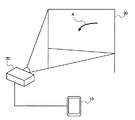
本発明の第1実施形態の画像処理システムについて図1から図10を参照して説明する。図1に本実施形態の画像処理システムのシステム構成例を示す。本実施形態の画像処理システムは、図1に示すように、例えば画像処理装置としての携帯情報端末と、投影手段としてのプロジェクタ20と、投影面であるホワイトボード30を含んで構成される。なお、ホワイトボード30にはユーザにより書き込みAが行われている。
[First Embodiment]
An image processing system according to a first embodiment of the present invention will be described with reference to FIGS. FIG. 1 shows a system configuration example of an image processing system according to the present embodiment. As shown in FIG. 1, the image processing system according to the present embodiment includes, for example, a portable information terminal as an image processing apparatus, a
なお、以下では携帯情報端末としてスマートフォン10を例に挙げて説明するが、本発明がこれに限定されるものでないことは言うまでもなく、携帯電話、タブレットPC、あるいはノートPC等であってもよい。また、本実施形態では撮像手段としてのカメラを内蔵するスマートフォン10を例に挙げて説明しているが、本発明の画像処理システムが、カメラ単体を含んで構成されるものであってもよい。
In addition, although the
図1に示すように、本実施形態においては、スマートフォン10とプロジェクタ20が有線または無線ネットワークで繋がっており、スマートフォン10に内蔵される記録媒体には会議で議論するための各種資料が保存されている。
As shown in FIG. 1, in the present embodiment, the
また、スマートフォン10は、少なくとも任意の情報を表示する表示手段としてのディスプレイと、ディスプレイへの接触を感知するセンシング手段としてのタッチパネルと、上述のカメラと、様々な処理を実現するための演算を行うCPUを搭載している。加えて、スマートフォン10には、上記の資料等を任意の画像情報としてプロジェクタ20へ転送する機能と、カメラで撮像した画像に対して画像処理を行える画像処理機能が含まれるアプリケーションプログラムがインストールされている。
In addition, the
そして、ホワイトボード30に対して、プロジェクタ20を使用してスマートフォン10から転送された資料の画像が投影される。ユーザはホワイトボード30に投影された資料を見ながら議論し、投影された資料の上にホワイトボードマーカー等を使って自由に手書きで文字や図形を書き込む。
Then, the image of the material transferred from the
また、ユーザがホワイトボード30に書き込んだ内容を保存したいと考えたとき、上述のアプリケーションを起動して撮影機能を呼び出す。撮影機能が呼び出されるとスマートフォン10はカメラから得られた画像を随時ディスプレイにプレビュー表示する。
When the user wants to save the content written on the
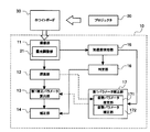
次に、本実施形態の画像処理装置としてのスマートフォン10の概略構成について図2を参照して説明する。本実施形態のスマートフォン10は、撮像部11と、探索部12と、第1補正パラメータ算出部13と、補正部14と、ぶれ検出手段としての加速度検知部15と、判定部16と、第1パラメータ補正部17とで構成される。
Next, a schematic configuration of the
撮像部11は露光を調整する露光調整部21を備えている。露光調整部21の動作については後述する。また、第1パラメータ補正部17は、姿勢パラメータ推定部171と姿勢パラメータ補正部172とを備えているが、これらについても後述する。
The
撮像部11は、上述したように本実施形態のスマートフォン10に内蔵されるカメラであり、これによりプロジェクタ20により画像が投影される投影面を撮像する。なお、本実施形態においては、投影される画像データはスマートフォン10からプロジェクタ20に上述のネットワークを介して送信される。
The
また、撮像部11は、プロジェクタ20により基準画像をホワイトボード30に投影した画像と一様画像をホワイトボード30に投影した画像を略同時に撮影する。これにより、各画像の撮像間での撮像部11、プロジェクタ20、及びホワイトボード30の位置関係は殆ど同じとなり、ぶれの少ない撮像画像を得ることができる。
Further, the
探索部12は、プロジェクタ20により基準画像をホワイトボード30に投影した画像をカメラにより撮像した撮像画像から、基準画像に対応する画像を探索する。ここで、基準画像とはコーナーを多く含む画像であって、あまり規則的でない画像であれば何でも良い。例えば図4に示すように、風になびく草原の画像等を用いればよい。但し、投影する基準画像と、資料として投影する画像を同サイズとしておく必要がある。
The
ここで、投影面いっぱいに表示された基準画像を含む撮像画像において基準画像を探索するということは、投影面が撮像画像においてどこにあるかを探索することに他ならない。撮像画像において投影面がわかるということは、一様画像の撮影画像において投影面がわかるということとほぼ同義である。 Here, searching for the reference image in the captured image including the reference image displayed on the entire projection plane is nothing but searching for where the projection plane is in the captured image. Knowing the projection plane in the captured image is almost synonymous with knowing the projection plane in the captured image of the uniform image.
また、仮に基準画像を最初に撮影し、撮像部11、プロジェクタ20、ホワイトボード30の位置で決まるパースペクティブ歪みを補正するパラメータを算出し、以降の撮影では、算出されたパラメータに基づいて歪み補正を行う手法をとったとする。この場合でも、撮影画像すべてに対して歪み補正が好適になされる。一方、この手法をとると、撮像部11、プロジェクタ20、ホワイトボード30の位置がずれることが無いようにユーザが意識する必要があり、不便である。
In addition, if a reference image is first taken, parameters for correcting perspective distortion determined by the positions of the
一方、本発明においては基準画像を毎回の撮影時に撮影することで、ユーザは、撮像部11、プロジェクタ20、ホワイトボード30の位置がずれることを気にすることなく、歪み補正がなされた撮像画像を得ることが出来る。
On the other hand, in the present invention, by capturing the reference image at each capturing, the user does not mind that the positions of the
また、歪み補正により、投影面が、基準画像に合致するような射影変換が施される。さらに、上述のように、基準画像と資料として投影する画像が同サイズであるため、補正された手書き画像の位置は投影していた資料における位置に完全に一致することになる。例えば、補正後の手書き画像に対して二値化を行い、背景を透過させて資料に重ね合わせれば、投影した資料に書き込んだ手書き内容をきれいに再現することができる。 Further, the projection conversion is performed so that the projection surface matches the reference image by the distortion correction. Furthermore, as described above, since the reference image and the image projected as the document have the same size, the position of the corrected handwritten image completely matches the position in the projected document. For example, if binarization is performed on the corrected handwritten image and the background is transmitted and superimposed on the material, the handwritten content written on the projected material can be reproduced beautifully.
第1補正パラメータ算出部13は、探索部12により探索した基準画像に対応する画像に基づいて撮像部11により撮像された撮像画像に対するパースペクティブ歪みを補正する第1補正パラメータを算出する。
The first correction
補正部14は、第1補正パラメータ算出部13により算出した第1補正パラメータに基づいて、一様画像を投影面に投影した画像を撮像した撮像画像に対して補正する。『一様画像』とは均一な色からなる画像のことをいう。なお、本実施形態においては、後述するように一様画像として白画像を使用するが、概ね一様でさえあれば黒画像を使用してもよい。また、一様画像として白画像や黒画像に限定されず、均一な色からなる画像であれば、その他の色からなる画像であってもよい。なお、例えば一様画像として真っ白な画像を投影すれば、手書き内容だけが撮像されることになり、資料を背景に撮像した場合に比べて、手書き内容が読みやすくなるという効果が得られる。
Based on the first correction parameter calculated by the first correction
撮像部11による基準画像と一様画像の撮像間のぶれを検出するぶれ検出手段としての加速度検知部15は、撮像部11に与えられた加速度を検知する加速度センサである。本実施形態においては、ぶれ検出手段として加速度センサを使用しているが、これに限定されず携帯情報端末等による撮影時のぶれを検出できる手段であればよい。
The
なお、加速度センサにより、基準画像と一様画像の撮像間での手ぶれを検知し、検知結果を第1補正パラメータに反映させることにより、撮像間での撮像部11、プロジェクタ20、ホワイトボード30の位置関係が変化しても、手ぶれの影響を軽減することが可能となる。
In addition, the camera shake between the reference image and the uniform image is detected by the acceleration sensor, and the detection result is reflected in the first correction parameter, so that the
判定部16は、加速度検知部15により検出したぶれの大きさと予め定められた第1の閾値との比較に基づいて補正部14による補正が可能かどうかを判定する。第1の閾値には、加速度検知部15により検知されたぶれの大きさを示す加速度のうち、補正部14による補正が許容される限界値を設定する。
The
例えば、基準画像と一様画像の撮像間での手ぶれが大きすぎるときには、基準画像の探索を実施できない。そのため、補正部14による補正が許容される限界値を設定し、加速度の許容限界値を超えて補正ができないと判定されたときは、ユーザに再撮影を促すこととする。こうすることで、後で確認したら画像がうまく補正されていなかったという不具合をなくすことが出来るので、ユーザは安心して本システムを使用することができる。
For example, when the hand movement between the reference image and the uniform image is too large, the reference image cannot be searched. Therefore, a limit value that allows correction by the
第1パラメータ補正部17は、加速度検知部15により検知された加速度が予め定められた第2の閾値以上であるとき、第1補正パラメータ算出部13により算出した第1補正パラメータを、検知された加速度に基づいて補正する。第2の閾値には、加速度検知部15により検知されたぶれの大きさを示す加速度のうち、第1補正パラメータを補正する必要があるかどうかを判定する境界値を設定する。
The first
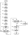
次に、本実施形態の画像処理の手順について図3のフローチャートを参照して説明する。まず、ユーザはスマートフォン10のディスプレイにおいてプレビューを見ながら、ホワイトボード30に照準を合わせ、ディスプレイをタッチすることでスマートフォン10に対して撮像指示を出す(ステップS1)。なお、これ以降はスマートフォン10により自動的に処理され、ユーザによる操作を要しない。
Next, the image processing procedure of this embodiment will be described with reference to the flowchart of FIG. First, while viewing the preview on the display of the
ユーザによる撮像指示の後、スマートフォン10からプロジェクタ20に一様画像として真っ白な画像を送信され、プロジェクタ20によりホワイトボード30に真っ白な画像が投影される(ステップS2)。このとき、ホワイトボード30にはユーザによる書き込みAだけが見えていることになる。
After the imaging instruction by the user, a pure white image is transmitted as a uniform image from the
続いて、撮像部11において、露光調整部21により画面の中央部を基準として露光調整が行われる(ステップS3)。これは、撮像画像全体が白飛びして書き込み内容が撮影できなくなるのを防ぐためである。また、本実施形態では、真っ白な画像を投影した後で撮像前に撮像部11の露光調整を行っているが、これは、白とびで手書き内容が撮像できなくなってしまう可能性を防ぐためである。
Subsequently, in the
なお、一般に露光調整は、撮像したいものに合わせて行うが、ユーザの意図する構図上、通常は撮像したいものが撮像面のどこにあるか不明である。そのため何らかの手段でユーザに露光調整の位置を指定させるカメラも少なくない。一方、本発明の場合、ユーザが撮影したいものはホワイトボードで有り、ほぼそれが真ん中になるように撮像されると考えられるため、基準位置を画面の中央部に固定している。これによりユーザに不要な手間を与える必要が無く、適切に露光を調整できる。 In general, exposure adjustment is performed in accordance with an object to be imaged, but it is usually unknown where the object to be imaged is on the imaging surface because of the composition intended by the user. Therefore, there are many cameras that allow the user to specify the position of exposure adjustment by some means. On the other hand, in the case of the present invention, what the user wants to photograph is a whiteboard, and it is considered that the image is taken so that it is almost in the middle, so the reference position is fixed at the center of the screen. Thereby, there is no need to give the user unnecessary trouble, and exposure can be adjusted appropriately.
さらに、投影する画像を切り替えるたびに、露光調整を行っていると、一様画像の撮像と基準画像の撮像の間に大きなタイムラグが発生してしまい、手振れ発生の可能性が増える。そのため、本実施形態では、露光調整を1回とすることが望ましい。 Furthermore, if exposure adjustment is performed every time the image to be projected is switched, a large time lag occurs between the imaging of the uniform image and the imaging of the reference image, and the possibility of camera shake increases. For this reason, in this embodiment, it is desirable to perform exposure adjustment once.
さらに、本実施形態における露光調整は手書き文字情報の白とびの発生を防止することに留意する。一方で、投影する一様画像の撮像画像は真っ白な画像であり、基準画像と比較すると、一様画像の撮像画像の方が必ず明るくなる。そのため一様画像の撮像で露光調整を行えば白とびの発生を確実に抑制することができ、露光調整を1回で済ませることが出来る。 Furthermore, it should be noted that the exposure adjustment in the present embodiment prevents overwriting of handwritten character information. On the other hand, the captured image of the uniform image to be projected is a pure white image, and the captured image of the uniform image is always brighter than the reference image. Therefore, if exposure adjustment is performed by capturing a uniform image, occurrence of overexposure can be reliably suppressed, and exposure adjustment can be completed only once.
その後、スマートフォン10の撮像部11によりホワイトボード30が撮影される(ステップS4)。なお、図においては簡略化のため、ホワイトボードを「WB」としている。そして、加速度検知部15により撮像部11に与えられた加速度を検知する(ステップS5)。
Thereafter, the
その後、予めスマートフォン10に保存されていた基準画像がプロジェクタ20に送信され、プロジェクタ20によりホワイトボード30の全面に基準画像が投影される(ステップS6)。そして、撮像部11により再度ホワイトボード30を撮影する(ステップS7)。
Thereafter, the reference image stored in the
その後、ステップS7において撮像部11により得られた撮像画像の中における、基準画像の位置を探索する(ステップS8)。基準画像の位置探索の手法については後述する。
Thereafter, the position of the reference image is searched for in the captured image obtained by the
その後、判定部16は、加速度検知部15により検知された加速度が第1の閾値よりも小さいか大きいかを判定する(ステップS9)。判定の結果、検知された加速度が第1の閾値より大きい場合には(ステップS9、大きい)、補正不可能であることをディスプレイに表示してユーザに通知し、再度の撮像指示を促す(ステップS1)。
Thereafter, the
一方、検知された加速度が第1の閾値よりも小さい場合(ステップS9、小さい)、次に検知された加速度が第2の閾値より小さいか大きいかを判定する(ステップS10)。検知された加速度が第2の閾値より小さい場合(ステップS10、小さい)、ステップS11へ移行する。一方、検知された加速度が第2の閾値より大きい場合(ステップS10、大きい)、探索された基準画像の位置を補正し(ステップS14)、ステップS11へ移行する。 On the other hand, when the detected acceleration is smaller than the first threshold (step S9, small), it is determined whether the next detected acceleration is smaller or larger than the second threshold (step S10). When the detected acceleration is smaller than the second threshold value (step S10, small), the process proceeds to step S11. On the other hand, when the detected acceleration is larger than the second threshold (step S10, large), the position of the searched reference image is corrected (step S14), and the process proceeds to step S11.
基準画像の探索位置を補正するステップS14においては、探索した基準画像の位置から撮像部11と基準画面との位置関係を表す緯度経度・回転・ズームパラメータを推定する。本発明においては、これらのパラメータを総称して姿勢パラメータとする。そして加速度センサの出力に基づいて、それらの姿勢パラメータを変化させて、もう一度基準画像の探索位置を再計算することで、探索位置の補正を行う。
In step S14 for correcting the search position of the reference image, latitude / longitude / rotation / zoom parameters representing the positional relationship between the
姿勢パラメータを推定することにより、加速度センサの出力に基づいて、姿勢パラメータを変化させ、もう一度基準画像の探索位置を計算しなおす。探索位置の補正を行えば、若干の手ぶれがあっても正確な歪み補正を行うことが可能である。結果として、ユーザは不必要に手ぶれを警戒しなくても良くなるのでユーザの利便性が向上する。 By estimating the posture parameter, the posture parameter is changed based on the output of the acceleration sensor, and the reference image search position is calculated again. If the search position is corrected, accurate distortion correction can be performed even with slight camera shake. As a result, since the user does not need to be wary of camera shake unnecessarily, the convenience for the user is improved.
そして、第1補正パラメータ算出部53は、得られた基準画像の位置から第1補正パラメータとしての射影変換マトリクスを算出し(ステップS12)、該マトリクスを用いて撮影画像に対して補正が行われる(ステップS13)。
Then, the first correction
次に、上述した処理手順における各処理のアルゴリズムについて具体的に説明する。 Next, the algorithm of each process in the process procedure mentioned above is demonstrated concretely.
[基準画像探索]
基準画像探索は基準画像の撮像画像から投影していた基準画像を探す処理である。図5に示すように一様画像の撮像画像はホワイトボード30に基準画像が投影された画像になっており、図中の黒丸で示した点の位置を見つけることが本処理の目的である。
[Reference image search]
The reference image search is a process of searching for a reference image projected from a captured image of the reference image. As shown in FIG. 5, the captured image of the uniform image is an image obtained by projecting the reference image onto the
そのため非特許文献1に記載された処理を行う。以下その概略について図6を参照して説明する。まず基準画像に対して、画像中で画素値が極大・極小となる点と、その基準サイズの検出を行う(ステップS101)。さらに、検出された極大・極小点それぞれについてコーナーらしい点だけを選別する(ステップS102)。なお、ここで言うコーナーとは画素値が2つの方向に変動している点を示すものとする。また、以下の説明において選別された極大・極小点のことを「Key point」とする。
Therefore, the process described in
その後、各「Key point」について、基準となる角度を算出する(ステップS103)。その後、算出した各「Key point」の基準サイズと基準角度に基づいて周辺領域を参照しながら、画素値勾配に基づいた128次元の特徴量を算出する(ステップS104)。同様に、一様画像の撮像画像についてもステップS105〜108の各処理を行うことによって、「Key point」の位置と各「Key point」についての特徴量を算出する。 Thereafter, a reference angle is calculated for each “Key point” (step S103). Thereafter, a 128-dimensional feature value based on the pixel value gradient is calculated while referring to the surrounding area based on the calculated reference size and reference angle of each “Key point” (step S104). Similarly, the process of steps S105 to 108 is performed on the captured image of the uniform image, thereby calculating the position of “Key point” and the feature amount for each “Key point”.
基準画像と、一様画像の撮像画像から得られた特徴量を比較し、ユークリッド距離が近いものを選別することで、2枚の画像における各「Key point」の対応点を見つける(ステップS109)。そして、それら対応点を用いて補正マトリクスを算出する(ステップS110)。これにより、基準画像の4隅を基準画像の撮像画像における基準画像の4隅に変換するマトリクスが得られる。このマトリクスによって、基準画像の4隅を変換すれば、基準画像の位置を表す4点を求めることができる(ステップS111)。なお、ステップS110で算出した補正マトリクスは上述した探索位置を補正するステップS14で使用する。 The feature amount obtained from the captured image of the reference image and the uniform image is compared, and the corresponding points of each “Key point” in the two images are found by selecting the ones having a short Euclidean distance (step S109). . Then, a correction matrix is calculated using these corresponding points (step S110). Thereby, a matrix for converting the four corners of the reference image into the four corners of the reference image in the captured image of the reference image is obtained. By converting the four corners of the reference image using this matrix, four points representing the position of the reference image can be obtained (step S111). The correction matrix calculated in step S110 is used in step S14 for correcting the search position described above.
以上のように、本実施形態では、基準画像の探索を多数の局所領域の対応を利用して確率的に行っている。全ての局所領域の対応をとらなくて良いため、手書き内容や、ホワイトボードの汚れ、投影面がホワイトボードよりも広い領域であったなどといった外的な影響に対して、非常にロバストに基準位置の探索を行うことが出来る。 As described above, in the present embodiment, the reference image search is performed stochastically using the correspondence of a large number of local regions. Since it is not necessary to deal with all local areas, the reference position is extremely robust against external influences such as handwritten content, dirt on the whiteboard, and the projection surface being an area wider than the whiteboard. Can be searched.
以下、図6で示した基準画像探索の処理工程を構成する各処理の詳細について説明する。 Hereinafter, details of each process constituting the process steps of the reference image search shown in FIG. 6 will be described.
[基準サイズ検出(ステップS101)]
ここでは、入力画像に対して画像処理を施し、基準サイズの検出とコーナーの位置検出とを同時に行う。まず、入力画像に対して段階的に標準偏差を変化させたガウシアンフィルタ5枚(σ0〜σ4)を施して、連続したぼかし画像を5枚得る。続いて、各ぼかし画像において画素値として極大、もしくは極小の位置を極値として検出する。
[Reference Size Detection (Step S101)]
Here, image processing is performed on the input image, and the detection of the reference size and the position of the corner are simultaneously performed. First, five Gaussian filters (σ 0 to σ 4) whose standard deviation is changed stepwise are applied to the input image to obtain five continuous blurred images. Subsequently, a position where the pixel value is maximum or minimum is detected as an extreme value in each blurred image.
検出した極値であって、かつ連続したぼかし画像における同座標の点を比較し、連続するぼかし画像においても極大、もしくは極小である点をコーナー候補として検出する。また、極値が得られたフィルタの標準偏差σnを基準サイズとして保持する。 The detected extreme value and the point of the same coordinate in the continuous blurred image are compared, and the point that is the maximum or the minimum in the continuous blurred image is detected as the corner candidate. Further, the standard deviation σn of the filter from which the extreme value is obtained is held as a reference size.
[基準画像におけるコーナー選別(ステップS102)]
ここでは、検出された各コーナー候補をについて変動が少ないもの、また変動が2方向に発生していないものを除去する。変動が1方向にしか発生していない点は例えば直線状の点で対応する点が正確に取れないので、変動が2方向になっているものを選択するのである。
[Corner Selection in Reference Image (Step S102)]
Here, the detected corner candidates are removed with little fluctuation and those with no fluctuation in two directions. For the point where the fluctuation occurs only in one direction, for example, since a corresponding point cannot be accurately obtained by a linear point, the one in which the fluctuation is in two directions is selected.
変動が2方向になっているものを選択するには、まず各画素に対して、例えば図8に示すような、縦方向の2次微分と横方向の2次微分、及び縦横方向の微分フィルタを画像へ適用することで、縦方向、横方向、縦横方向の変動を示すような応答を求め、ヘシアンマトリクスを作成する。 In order to select a pixel whose variation is in two directions, first, for example, as shown in FIG. 8, for each pixel, a second-order differential in the vertical direction, a second-order differential in the horizontal direction, and a differential filter in the vertical and horizontal directions. Is applied to the image to obtain a response indicating fluctuations in the vertical direction, the horizontal direction, and the vertical and horizontal directions, and a Hessian matrix is created.
その固有値を求めると、最も変動の大きい方向とその変動成分αが求まる。同様に、該方向に直行する方向の変動成分βも求めることができる。この時画像の構造に対してαとβがどのような値になるかの関係は図7のように示せる。なお、α≧βなので斜線部は存在しない。小さい方の変動βが十分に大きい場合、注目画素の周辺は少なくとも2つの方向に対して大きく変動しているということがいえるのでは該領域は、何もない領域ではなく、単純なエッジでもない。つまり、コーナーとして検出できる。 When the eigenvalue is obtained, the direction with the largest fluctuation and the fluctuation component α are obtained. Similarly, the fluctuation component β in the direction perpendicular to the direction can also be obtained. At this time, the relationship between α and β with respect to the image structure can be shown as shown in FIG. Since α ≧ β, there is no hatched portion. If the smaller fluctuation β is sufficiently large, it can be said that the periphery of the pixel of interest is greatly fluctuating in at least two directions, and the area is not an empty area or a simple edge. . That is, it can be detected as a corner.
縦横方向に変動のある領域をコーナーとして検出すると斜め方向への変動を検出することができない。一方で斜め方向の変動を検出するために様々な方向の変動を検出すると非効率的であるが、固有値を求めて小さい方の変動βを調べると、最も変動が大きい方向に直行する変動が一意に求まる。小さいほうの変動が十分に大きければコーナーと判定することで、様々な向きを向いたコーナーを効率よく検出できるため、コーナー検出のための計算コストが小さくなる。 If a region that fluctuates in the vertical and horizontal directions is detected as a corner, the variation in the oblique direction cannot be detected. On the other hand, it is inefficient to detect fluctuations in various directions in order to detect fluctuations in the diagonal direction. However, if the smaller fluctuation β is examined by obtaining the eigenvalue, the fluctuation that goes straight in the direction with the largest fluctuation is unique. I want to. If the smaller variation is sufficiently large, it is possible to efficiently detect corners facing various directions by determining that the corner is a corner, and thus the calculation cost for corner detection is reduced.
[基準画像における基準角度算出(ステップS103)]
基準角度算出ステップでは、周辺の濃度勾配が最も大きい方向を基準角度として以下のように算出する。画像の画素値をL(u,v)、勾配強度をm(u,v)、勾配方向をθ(u,v)とすると、それぞれは以下のように算出できる。
[Reference Angle Calculation in Reference Image (Step S103)]
In the reference angle calculation step, the calculation is performed as follows using the direction in which the peripheral density gradient is the largest as the reference angle. If the pixel value of the image is L (u, v), the gradient strength is m (u, v), and the gradient direction is θ (u, v), each can be calculated as follows.

その後、勾配方向θ(u,v)を10度ずつ、36方向に離散化したヒストグラムを用意する。該ヒストグラムには、勾配強度m(u,v)に対し、注目画素を中心とするガウシアンを掛け合わせた値を加算していく。該ヒストグラムに於いて最も大きな値を示す角度が最も変動が大きい方向、つまり基準方向となる。 Thereafter, a histogram is prepared in which the gradient direction θ (u, v) is discretized in 36 directions by 10 degrees. In the histogram, a value obtained by multiplying the gradient intensity m (u, v) by Gaussian centered on the target pixel is added. The angle showing the largest value in the histogram is the direction with the largest fluctuation, that is, the reference direction.
[基準画像における特徴量算出(ステップS104)]
入力画像においてコーナーを中心として基準方向を上とし、また基準サイズσnを用いてコーナー近辺の半径2σnとなる領域を切り出し、一辺4ブロックの計16ブロックに分割する。ブロックごとに45度ずつ、8方向の勾配ヒストグラムを作成することにより、4×4×8=128次元の特徴量が得られる。このように特徴量は基準サイズと基準角度を用いて正規化されているので、投影画像と撮影画像との間で画像の大きさの変化や回転が発生したとしても対応する点の特徴量は類似した値になりやすい。
[Feature amount calculation in reference image (step S104)]
In the input image, the reference direction is centered on the corner and the region having the radius 2σ n near the corner is cut out using the reference size σ n , and divided into 16 blocks of 4 blocks on each side. By creating a gradient histogram in 8 directions at 45 degrees for each block, 4 × 4 × 8 = 128-dimensional feature values can be obtained. Since the feature amount is normalized by using the reference size and the reference angle in this way, the feature amount of the corresponding point even if a change or rotation of the image size occurs between the projected image and the captured image, It tends to be a similar value.
[特徴量比較(ステップS109)・補正マトリクス算出(ステップS110)]
ここまでで投影画像と撮影画像とで、それぞれ多数の「Key point」およびその周辺で正規化された特徴量が得られている。これらから変換マトリクスを求める。まず、投影画像と撮影画像とで特徴量のユークリッド距離を算出し、それぞれ最も近ものを選択することで、各「Key point」の対応が取れているものとする。
[Feature amount comparison (step S109) / Correction matrix calculation (step S110)]
Up to this point, a large number of “Key points” and their normalized feature quantities are obtained for the projected image and the captured image. A conversion matrix is obtained from these. First, it is assumed that the correspondence between each “Key point” is obtained by calculating the Euclidean distance of the feature amount between the projected image and the captured image, and selecting the closest one.
ここで投影画像における「Key point」の位置を点列として(x0,y0,z0),(x1,y1,z1),・・・,(xn,yn,zn)とし、一方で撮影画像における「Key point」の位置を点列として、(x′0,y′0,z′0),(x′1,y′1,z′1),・・・,(x′n,y′n,z′n)とする。なお、添え字が同じなら対応する点であると判定する。そして、以下の変換マトリクスによって対応点が射影される。 Here, (x 0 , y 0 , z 0 ), (x 1 , y 1 , z 1 ),..., (X n , y n , z n ) with the position of “Key point” in the projection image as a point sequence. On the other hand, the position of the “Key point” in the photographed image is set as a point sequence, and (x ′ 0 , y ′ 0 , z ′ 0 ), (x ′ 1 , y ′ 1 , z ′ 1 ),. , (X ′ n , y ′ n , z ′ n ). If the subscripts are the same, it is determined that the corresponding point. The corresponding points are projected by the following conversion matrix.
そして、以下の式で示されるそれらの二乗誤差和を最小化する用にHの各要素を求めれば良い。Levenberg‐Marquardt法などを用いて数値的に解くことが可能である。 And each element of H should just be calculated | required in order to minimize those square error sums shown by the following formula | equation. It can be solved numerically using the Levenberg-Marquardt method.
[探索位置補正(ステップS14)]
探索位置補正について図9を参照して説明する。補正マトリクスは3×3のマトリクスであった。このマトリクスは、本来、真正面から適正な距離で見れば、単位行列であったはずであるところを、図10に示すようにチルトθ、経度f、緯度e、ズームgで見たために、歪んでしまったものである。
[Search position correction (step S14)]
The search position correction will be described with reference to FIG. The correction matrix was a 3 × 3 matrix. This matrix is originally distorted because it should have been a unit matrix when viewed at an appropriate distance from the front, as seen from tilt θ, longitude f, latitude e, and zoom g as shown in FIG. It is a fool.
この歪みのプロセスは、以下の式に示すような線形変換で表すことができ、ここまでに補正マリクスにおけるh11,h12,h21,h22がそれぞれa,b,c,dに対応する。未知数であるチルトθ、経度f、緯度e、ズームgに対して式が4つあるため、姿勢パラメータを推定するステップS201において連立方程式を解くことで、全未知数を求めることが出来る。 This distortion process can be expressed by a linear transformation as shown in the following formula, and so far, h 11 , h 12 , h 21 , and h 22 in the correction marix correspond to a, b, c, and d, respectively. . Since there are four formulas for the unknown tilt θ, longitude f, latitude e, and zoom g, all unknowns can be obtained by solving simultaneous equations in step S201 for estimating posture parameters.
その後、加速度センサにより得られた、一様画像の撮像と、基準画像の撮像との間で発生した向きの変化を用いて、姿勢パラメータを補正するステップS202にてチルトθ、経度f、緯度e、ズームgを補正すれば、その後の座標変換(ステップS203)により一様画像の撮像と基準画像の撮像との間で発生した向きの振れを正確に補正することが出来る。また、加速度センサで検知した平行移動成分を用いてh13,h23を補正すれば手ぶれによる平行移動も補正することが出来る。但し、こちらについては、投影面のサイズが不明なため、正確に補正することは不可能であるため、移動量と補正量を経験的に決めている。 After that, the tilt θ, longitude f, and latitude e are corrected in step S202 using the change in orientation that occurs between the imaging of the uniform image and the imaging of the reference image obtained by the acceleration sensor. If the zoom g is corrected, it is possible to accurately correct the shake of the direction that occurs between the imaging of the uniform image and the imaging of the reference image by the subsequent coordinate conversion (step S203). Further, if h 13 and h 23 are corrected using the translation component detected by the acceleration sensor, translation due to camera shake can also be corrected. However, since the size of the projection plane is unknown for this, it is impossible to correct it accurately, so the movement amount and the correction amount are determined empirically.
以上のように、本実施形態によれば、歪み補正マトリクスから推定したパラメータと、加速度センサの検知結果によって若干の手振れに対してロバストに一様画像の撮像における投影面の推定が出来るため、良好な歪み補正を施した画像が得られる可能性が高くなる。 As described above, according to the present embodiment, it is possible to estimate the projection plane in capturing a uniform image robustly with respect to slight camera shake based on the parameters estimated from the distortion correction matrix and the detection result of the acceleration sensor. There is a high possibility that an image subjected to proper distortion correction will be obtained.
[補正パラメータ算出(ステップS12)]
ここまでに基準画像の4隅と一様画像の撮像画像における基準画像の4隅がわかっているので、射影変換マトリクスとしての歪み補正マトリクスを簡単に算出することが出来る。歪み補正マトリクスは撮影した画像中の点(xn,yn)を基準画像における点(x′n,y′n)に射影するようなマトリクスである。以下の式で示すように未知数が8となるため、8元連立方程式を立てて解くことが必要になる。
[Correction parameter calculation (step S12)]
Since the four corners of the reference image and the four corners of the reference image in the captured image of the uniform image are known so far, the distortion correction matrix as the projective transformation matrix can be easily calculated. The distortion correction matrix is a matrix that projects the point (x n , y n ) in the photographed image to the point (x ′ n , y ′ n ) in the reference image. Since the unknown is 8, as shown in the following equation, it is necessary to establish and solve an 8-ary simultaneous equation.
ここで、撮影画像中における4点(xn,yn)と基準画像における4点(x′n,y′n)を指定すればx、yそれぞれにつき4つの方程式、合わせて8つの方程式を作ることが可能であり、マトリクスの要素を全て求めることが可能である。なお、添え字のn(0≦n≦4)は各点のインデックス番号を示すものとする。 Here, if 4 points (x n , y n ) in the captured image and 4 points (x ′ n , y ′ n ) in the reference image are designated, 4 equations for x and y respectively, and 8 equations in total are obtained. It is possible to make all the elements of the matrix. Note that the subscript n (0 ≦ n ≦ 4) indicates the index number of each point.
4点を代入してまとめると以下の連立方程式になるので、これをGauss‐Jordan法等で数値解析的に解くと射影変換マトリクスを求めることができる。 Substituting the four points together results in the following simultaneous equations. If this is solved numerically by the Gauss-Jordan method or the like, a projective transformation matrix can be obtained.
なお、上述したように本発明の第1実施形態では、一様画像として真っ白な画像を用いたが、概ね一様でさえあれば、黒画像でも構わない。但し、白とびを抑制するための露光は一様画像の投影画像と基準画像の投影画像とで明るいほうの画像に合わせたほうが良い。また、本発明においては、必ずしも基準画像を後に撮影する必要は無い。よって、ユーザの利便性を考え、基準画像と一様画像を投影する順番や、露光調整を行うための画像の選択を適宜変更しても良い。 As described above, in the first embodiment of the present invention, a pure white image is used as a uniform image, but a black image may be used as long as it is substantially uniform. However, the exposure for suppressing overexposure should be matched to the brighter image of the projected image of the uniform image and the projected image of the reference image. In the present invention, it is not always necessary to take a reference image later. Therefore, in consideration of user convenience, the order in which the reference image and the uniform image are projected and the selection of an image for performing exposure adjustment may be changed as appropriate.
[第2実施形態]
次に、本発明の第2実施形態の画像処理システムについて図11及び図12を参照して説明する。システム構成としては第1実施形態と同様であるが、加速度センサのセンシング結果に基づいて歪み補正パラメータを補正するのではなく、画像処理によって得られた結果に基づいて歪み補正パラメータを補正する点で第1実施形態と異なっている。なお、以下において第1実施形態と同様の構成・処理については説明を省略する。
[Second Embodiment]
Next, an image processing system according to a second embodiment of the present invention will be described with reference to FIGS. The system configuration is the same as that of the first embodiment, but the distortion correction parameter is not corrected based on the sensing result of the acceleration sensor, but is corrected based on the result obtained by image processing. This is different from the first embodiment. Note that the description of the same configuration and processing as in the first embodiment will be omitted below.
本発明の第2実施形態の画像処理装置としてのスマートフォン50の概略構成としては、図11に示すように、第1実施形態における加速度検知部15、判定部16、並びに第1パラメータ補正部17に代えて、第2補正パラメータ算出部56及び第2パラメータ補正部57を備えたことに特徴がある。
As shown in FIG. 11, the schematic configuration of the
第2補正パラメータ算出部56は、一様画像の撮像において抽出したエッジを第2補正パラメータとして算出する。また、第2パラメータ補正部57は、第1補正パラメータ算出部53により算出した第1補正パラメータを、第2補正パラメータ算出部56により算出した第2補正パラメータに基づいて補正する。つまり、第2補正パラメータとしてのエッジに基づいて第1補正パラメータとしての射影変換マトリクスを補正するのである。
The second correction
次に、本実施形態の画像処理手順について、図12を参照して説明する。なお、上述したように、第1実施形態と同様の手順については説明を省略する。ステップS303における露光調整の後、加速度検出部55によりスマートフォン50に発生している加速度をモニタリングして、加速度が限りなく小さくなるまで待機する(ステップS304)。なお、加速度の値がゼロであると尚よい。
Next, the image processing procedure of this embodiment will be described with reference to FIG. As described above, the description of the same procedure as in the first embodiment is omitted. After the exposure adjustment in step S303, the
その後、各投影画像を撮像し(ステップS306からS308)、基準画像探索の処理において、第2補正パラメータ算出部は、一様画像の撮像において第2補正パラメータとしてのエッジを抽出する(ステップS309)。この基準画像探索で得られた基準画像の4隅を直線でつなぎ、その直線周辺付近以外ではエッジ検出を行わないようにする。 Thereafter, each projected image is captured (steps S306 to S308), and in the reference image search process, the second correction parameter calculation unit extracts an edge as the second correction parameter in capturing the uniform image (step S309). . The four corners of the reference image obtained by this reference image search are connected by a straight line, and edge detection is not performed except in the vicinity of the straight line.
その後、第2パラメータ補正部57は、検出されたエッジに対してhough変換で直線を求め、その交点を持って、補正後の基準画像位置とする(ステップS310)。そして、補正後の基準画像位置から第1補正パラメータとしての射影変換マトリクスを算出し(ステップS311)、補正部54は該マトリクスを用いて一様画像の撮像に対して補正が行われる(ステップS312)。
Thereafter, the second
本発明の第2実施形態によれば、基準画像の撮像において基準画像を探索した後、基準画像が有ると考えられる領域周辺でエッジ探索を行い、投影面を探索することで、手ぶれが発生しても、良好に歪み補正が行うことが可能となるのである。 According to the second embodiment of the present invention, after searching for a reference image in capturing a reference image, an edge search is performed around an area where the reference image is considered to be present, and a projection plane is searched, thereby causing camera shake. However, the distortion can be corrected well.
また、本発明の第2実施形態において、撮像指示はスマートフォン50の表示部をタッチすることで行われるが、この動作は非常に手ぶれを発生させやすい。そのため、本発明の第2実施形態においてば、撮像指示があってすぐに撮像を行うのではなく、タッチしてから、スマートフォンの動きが安定するまで撮像を行わない構成としている。これにより手ぶれ発生の可能性が低まり、良好な歪み補正画像を得ることが可能となるのである。
Further, in the second embodiment of the present invention, the imaging instruction is performed by touching the display unit of the
なお、上述する各実施の形態は、本発明の好適な実施の形態であり、本発明の要旨を逸脱しない範囲内において種々変更実施が可能である。例えば、上述した本発明の実施形態においては、図2で示したようなシステム構成を仮定したが、本発明はカメラ、プロジェクタ、PCなどの演算装置があれば実施できるため、他にも様々なシステムへの適用が可能である。 Each of the above-described embodiments is a preferred embodiment of the present invention, and various modifications can be made without departing from the scope of the present invention. For example, in the above-described embodiment of the present invention, the system configuration as shown in FIG. 2 is assumed. However, the present invention can be implemented with a computing device such as a camera, a projector, and a PC. It can be applied to the system.
また、演算装置はPC上で動作するソフトウェアでも実装できるが、専用の回路を組んでハードウェアで実現しても全く問題ない。以下において他の様々なシステム構成を例示する。 The arithmetic unit can also be implemented by software operating on a PC, but there is no problem if it is realized by hardware by building a dedicated circuit. Various other system configurations will be exemplified below.
[他のシステム構成1]
図13(a)に示すように、他のシステム構成1では、プロジェクタ102にカメラ機能1022をもたせ、ノートPC103から送られてくる画像データに基づいてプロジェクタ102がホワイトボード101へ投影を行うものである。このとき、基準画像はプロジェクタ102に内蔵される記録部に予め保存されていた画像を用いる。また、これまでに説明した補正パラメータ算出手段、パラメータ補正手段、補正手段といった画像処理手段が、プロジェクタ102にハードウェアとして実装されているものとする。
[Other system configuration 1]
As shown in FIG. 13A, in another
但し、一部の基準画像はノートPC103に保持されていても良いし、画像処理手段の一部がノートPC103のCPUを用いてソフトウェア的に実装されていてもよい。
However, a part of the reference image may be held in the
[他のシステム構成2]
図13(b)に示す他のシステム構成2では、カメラ204とプロジェクタ202と演算装置としてのPC203のように、それぞれ別のデバイス上に実装されているものとする。補正パラメータ算出手段、補正パラメータ修正手段、補正手段といった画像処理手段をPC203上で動作するソフトウェアで実装すれば、既存のデバイスを用いて本発明を実施することが可能である。
[Other system configuration 2]
In another system configuration 2 shown in FIG. 13B, it is assumed that the system is mounted on different devices such as a
[他のシステム構成3]
最後にスマートフォン303のみを用いたシステム構成について図13(c)を参照して説明する。他のシステム構成3では、補正パラメータ算出手段や補正パラメータ修正手段、補正手段といった画像処理手段が第1実施例同様、スマートフォン上で動作するソフトウェアとして実装される。近年ではカメラが搭載されたスマートフォンは珍しくなく、さらにプロジェクタ機能を搭載したスマートフォンも近年登場しており、この構成で本発明の効果を十分に得ることが可能である。
[Other system configuration 3]
Finally, a system configuration using only the
10、50 スマートフォン
11、51 撮像部
12、52 探索部
13、53 第1補正パラメータ算出部
14、54 補正部
15、55 加速度検知部
16 判定部
17 第1パラメータ補正部
20 プロジェクタ
21 露光調整部
30 ホワイトボード
56 第2補正パラメータ算出部
57 第2パラメータ補正部
171 姿勢パラメータ推定部
172 姿勢パラメータ補正部
DESCRIPTION OF
Claims (10)
前記投影手段により基準画像を投影面に投影した画像を前記撮像手段により撮像した撮像画像から、前記基準画像に対応する画像を探索する探索手段と、
前記探索手段により探索した画像に基づいて前記撮像画像に対するパースペクティブ歪みを補正する第1補正パラメータを算出する第1補正パラメータ算出手段と、
前記第1補正パラメータ算出手段により算出した第1補正パラメータに基づいて、一様画像を投影面に投影した画像を撮像した撮像画像に対して補正する補正手段と、
を備えることを特徴とする画像処理システム。 Imaging means for imaging a projection plane on which an image is projected by the projection means;
Search means for searching for an image corresponding to the reference image from the captured image obtained by imaging the image obtained by projecting the reference image on the projection plane by the projection means by the imaging means;
First correction parameter calculation means for calculating a first correction parameter for correcting perspective distortion for the captured image based on the image searched by the search means;
Correction means for correcting a captured image obtained by imaging an image obtained by projecting a uniform image on a projection plane based on the first correction parameter calculated by the first correction parameter calculation means;
An image processing system comprising:
前記ぶれ検出手段により検出したぶれの大きさと予め定められた第1の閾値との比較に基づいて前記補正手段による補正が可能かどうかを判定する判定手段と、
を備えることを特徴とする請求項1又は2記載の画像処理システム。 Blur detection means for detecting blur between a reference image and a uniform image captured by the imaging means;
A determination unit that determines whether correction by the correction unit is possible based on a comparison between the magnitude of the shake detected by the shake detection unit and a predetermined first threshold;
The image processing system according to claim 1, further comprising:
前記加速度検知手段により検知された加速度が予め定められた第2の閾値以上であるとき、第1補正パラメータ算出手段により算出した第1補正パラメータを、前記検知された加速度に基づいて補正する第1パラメータ補正手段と、
を備えることを特徴とする請求項3記載の画像処理システム。 The shake detecting means is an acceleration detecting means for detecting an acceleration given to the imaging means,
When the acceleration detected by the acceleration detection means is equal to or greater than a predetermined second threshold, the first correction parameter calculated by the first correction parameter calculation means is corrected based on the detected acceleration. Parameter correction means;
The image processing system according to claim 3, further comprising:
前記探索手段により探索された画像の位置からカメラと投影面に対する姿勢パラメータを推定する姿勢パラメータ推定手段と、
前記加速度検知手段により検知された加速度に基づいて、前記探索された画像の位置を再計算することにより前記姿勢パラメータを補正する姿勢パラメータ補正手段と、
を備えることを特徴とする請求項4記載の画像処理システム。 The first parameter correction means includes
Attitude parameter estimation means for estimating an attitude parameter with respect to the camera and the projection plane from the position of the image searched by the search means;
Attitude parameter correction means for correcting the attitude parameter by recalculating the position of the searched image based on the acceleration detected by the acceleration detection means;
The image processing system according to claim 4, further comprising:
前記第1補正パラメータ算出手段により算出した第1補正パラメータを、第2補正パラメータ算出手段により算出した第2補正パラメータに基づいて補正する第2パラメータ補正手段とを備え、
前記補正手段は、第2パラメータ補正手段により補正された第1補正パラメータに基づいて、一様画像を投影面に投影した画像を撮像した撮像画像に対して補正することを特徴とする請求項1又は2記載の画像処理システム。 Second correction parameter calculating means for calculating a second correction parameter for estimating the position of the projection plane based on the uniform image;
Second parameter correction means for correcting the first correction parameter calculated by the first correction parameter calculation means based on the second correction parameter calculated by the second correction parameter calculation means;
2. The correction unit corrects a captured image obtained by capturing an image obtained by projecting a uniform image on a projection plane based on the first correction parameter corrected by the second parameter correction unit. Or the image processing system of 2.
Priority Applications (1)
| Application Number | Priority Date | Filing Date | Title |
|---|---|---|---|
| JP2013012029A JP2014143630A (en) | 2013-01-25 | 2013-01-25 | Image processing system |
Applications Claiming Priority (1)
| Application Number | Priority Date | Filing Date | Title |
|---|---|---|---|
| JP2013012029A JP2014143630A (en) | 2013-01-25 | 2013-01-25 | Image processing system |
Publications (1)
| Publication Number | Publication Date |
|---|---|
| JP2014143630A true JP2014143630A (en) | 2014-08-07 |
Family
ID=51424584
Family Applications (1)
| Application Number | Title | Priority Date | Filing Date |
|---|---|---|---|
| JP2013012029A Pending JP2014143630A (en) | 2013-01-25 | 2013-01-25 | Image processing system |
Country Status (1)
| Country | Link |
|---|---|
| JP (1) | JP2014143630A (en) |
-
2013
- 2013-01-25 JP JP2013012029A patent/JP2014143630A/en active Pending
Similar Documents
| Publication | Publication Date | Title |
|---|---|---|
| WO2018214365A1 (en) | Image correction method, apparatus, device, and system, camera device, and display device | |
| JP6116486B2 (en) | Dimension measurement method | |
| US9342742B2 (en) | Systems and methods for mobile image capture and processing | |
| JP4341629B2 (en) | Imaging apparatus, image processing method, and program | |
| JP4556813B2 (en) | Image processing apparatus and program | |
| US10915998B2 (en) | Image processing method and device | |
| KR101450782B1 (en) | Image processing device and program | |
| JP2007074578A (en) | Image processor, photography instrument, and program | |
| US20180295273A1 (en) | Device and method for detecting regions in an image | |
| JP2016212784A (en) | Image processing apparatus and image processing method | |
| JP2016123044A (en) | Subject tracking device, and control method and program therefor | |
| JP2018046337A (en) | Information processing device, program and control method | |
| US9871947B2 (en) | Image processing apparatus, image processing method, and storage medium | |
| JP6564136B2 (en) | Image processing apparatus, image processing method, and program | |
| US10514591B2 (en) | Camera apparatus, image processing device, and image processing method | |
| US20210281742A1 (en) | Document detections from video images | |
| JP2013257643A (en) | Image processing system, and program | |
| JP2013149034A (en) | Image display apparatus, image display method, and program | |
| KR101132976B1 (en) | Mobile device with a plurality of camera, method for display using the sane | |
| JP2014143630A (en) | Image processing system | |
| JP6736916B2 (en) | Information processing apparatus, information processing method, and program | |
| JP6600090B2 (en) | Image processing apparatus, image processing method, and program | |
| US20160224854A1 (en) | Information processing apparatus, information processing method, and storage medium | |
| WO2018061430A1 (en) | Measurement apparatus, measurement method, measurement program, and recording medium | |
| CN114143442B (en) | Image blurring method, computer device, and computer-readable storage medium |