JP2014143156A - LED lamp - Google Patents

LED lamp Download PDF

Info

Publication number
JP2014143156A
JP2014143156A JP2013031286A JP2013031286A JP2014143156A JP 2014143156 A JP2014143156 A JP 2014143156A JP 2013031286 A JP2013031286 A JP 2013031286A JP 2013031286 A JP2013031286 A JP 2013031286A JP 2014143156 A JP2014143156 A JP 2014143156A
Authority
JP
Japan
Prior art keywords
led
lens
light
led lamp
concave hole
Prior art date
Legal status (The legal status is an assumption and is not a legal conclusion. Google has not performed a legal analysis and makes no representation as to the accuracy of the status listed.)
Pending
Application number
JP2013031286A
Other languages
Japanese (ja)
Inventor
Tomohiko Inoue
智彦 井上
Current Assignee (The listed assignees may be inaccurate. Google has not performed a legal analysis and makes no representation or warranty as to the accuracy of the list.)
Phoenix Electric Co Ltd
Original Assignee
Phoenix Electric Co Ltd
Priority date (The priority date is an assumption and is not a legal conclusion. Google has not performed a legal analysis and makes no representation as to the accuracy of the date listed.)
Filing date
Publication date
Application filed by Phoenix Electric Co Ltd filed Critical Phoenix Electric Co Ltd
Priority to JP2013031286A priority Critical patent/JP2014143156A/en
Priority to CN201310740323.XA priority patent/CN103899949A/en
Publication of JP2014143156A publication Critical patent/JP2014143156A/en
Pending legal-status Critical Current

Links

Images

Abstract

PROBLEM TO BE SOLVED: To develop an LED lamp that resembles a conventional incandescent lamp in a light emission shape, and can create an antique or nostalgic atmosphere.SOLUTION: An LED lamp includes: a surface-emitting LED 12; a transparent solid columnar lens 14 receiving light emitted from the LED 12 at a bottom surface 14a opposed to the light-emitting surface 12a of the LED 12, and formed of a concave hole 14g for scattering light on a top surface 14h; and power supply means 20 for supplying power to the LED 12. The lens 14 is a circular column, a truncated cone, a polygonal pillar or a truncated pyramid. The concave hole 14g is the circular column, the truncated cone, the polygonal pillar or the truncated pyramid, gradually widened toward the top surface 14h of the lens 14.

Description

本発明は、発光形状が従来の白熱電球と似ているLEDランプに関する。   The present invention relates to an LED lamp whose light emission shape is similar to a conventional incandescent bulb.

従来の白熱電球に比べて消費電力が低く、かつ、長寿命といった長所を有する発光ダイオード(以下、「LED」という。)は、需要者のエコロジー意識の高まりとともに、省エネ対策のひとつとしてその使用範囲が急速に広まっており、とりわけ白熱灯の代替としてLEDが組み込まれたLED発光装置を使用したいという要望が高まっている(特許文献1)。   Light-emitting diodes (hereinafter referred to as “LEDs”), which have lower power consumption and longer life than conventional incandescent bulbs, are used as one of the energy-saving measures along with increasing ecological awareness of consumers. Is rapidly spreading, and in particular, there is an increasing demand for using an LED light-emitting device incorporating an LED as an alternative to an incandescent lamp (Patent Document 1).

その結果、シャンデリアを初めとする光源としてのミニクリプトン型電球、一般照明等の用途に広く使用されているボール型電球などの白熱電球からこれらを模したLED電球に急速に置き換わりつつある。これはLED素子の効率アップや放熱技術の向上により、LED素子の明るさが上記白熱電球の明るさに接近したことによる。しかしながら、LED素子の明るさが白熱電球の明るさに接近したとしてもLED素子から出る光は、均斉な光であって従来の白熱電球のフィラメントからの光とは全く異なる。   As a result, incandescent lamps such as mini-krypton type light bulbs as light sources such as chandeliers and ball-type light bulbs widely used for general illumination are rapidly being replaced with LED light bulbs that imitate them. This is because the brightness of the LED element approaches the brightness of the incandescent light bulb by improving the efficiency of the LED element and improving the heat dissipation technology. However, even if the brightness of the LED element approaches the brightness of the incandescent bulb, the light emitted from the LED element is uniform light and is completely different from the light from the filament of the conventional incandescent bulb.

しかしながら、室内照明では、蛍光灯のような単に明るさだけを要求するような場合だけでなく、例えば店舗照明のようにアンティーク或いはレトロな照明が要求される場合がある。そのような場合には現在のLEDランプでは対応することができない。   However, in the interior lighting, there are cases where antique or retro lighting such as store lighting is required, as well as a case where only brightness is required such as a fluorescent lamp. In such a case, the current LED lamp cannot cope.

実用新案登録第3143412号公報Utility Model Registration No. 314312

本発明はこのような問題に鑑みてなされたもので、発光形状が従来の白熱電球と似ており、アンティーク或いはレトロな雰囲気を醸し出すことができるLEDランプの開発をその課題とする。   This invention is made | formed in view of such a problem, The light emission shape is similar to the conventional incandescent lamp, and it makes it the subject to develop the LED lamp which can bring out an antique or retro atmosphere.

請求項1に記載された発明は、
面発光型のLED12と、
前記LED12の発光面12aに対向する底面14aで前記LED12から放射される光を受け入れ、頂面14hに光散乱用の凹穴14gが形成された透明中実柱状のレンズ14と、
前記LED12に給電するための給電手段20とを備えており、
前記レンズ14が円柱、多角柱、円錐台又は多角錐台に形成され、凹穴14gがレンズ14の頂面14hに向かって次第に拡開する円錐、円錐台、多角錐又は多角錐台であることを特徴とするLEDランプ10である。
The invention described in claim 1
A surface emitting LED 12;
A transparent solid columnar lens 14 that receives light emitted from the LED 12 at the bottom surface 14a facing the light emitting surface 12a of the LED 12 and has a concave hole 14g for light scattering formed on the top surface 14h;
Power supply means 20 for supplying power to the LED 12,
The lens 14 is formed in a cylinder, a polygonal column, a truncated cone or a polygonal frustum, and the concave hole 14g is a cone, a truncated cone, a polygonal pyramid or a polygonal frustum that gradually expands toward the top surface 14h of the lens 14. LED lamp 10 characterized by the following.

請求項2に記載された発明は、請求項1のLEDランプ10において、凹穴14gに代わる線状に連続する点14iがレンズ14内に形成されていることを特徴とする。   The invention described in claim 2 is characterized in that, in the LED lamp 10 of claim 1, a linearly continuous point 14i is formed in the lens 14 instead of the concave hole 14g.

請求項3に記載された発明は、請求項2のLEDランプ10において、点14iの連続線がレンズ14の一正面から見て略M字形を描き、頂面14hから見て略V字形を描くように形成されていることを特徴とする。   According to a third aspect of the present invention, in the LED lamp 10 of the second aspect, the continuous line of the points 14i draws a substantially M shape when viewed from one front surface of the lens 14, and a substantially V shape when viewed from the top surface 14h. It is formed as follows.

請求項4に記載された発明は、請求項1〜3に記載のLEDランプ10において、光散乱用の凹穴14gの表面が粗面に形成されていることを特徴とする。   The invention described in claim 4 is characterized in that, in the LED lamp 10 described in claims 1 to 3, the surface of the light scattering concave hole 14g is formed into a rough surface.

請求項1の発明によれば、レンズ14内で乱反射した光は凹穴14gの周囲であたかもフィラメントのように光り、アンティーク或いはレトロな雰囲気を醸し出す。同様に、請求項2,3においても、点14iの連続体がフィラメントのように光ることになるので、同様の効果を醸し出す。また、凹穴14gの表面が粗面に形成されておれば、当該表面でより強い反射が得られればさらに前述の効果を強調することができる。   According to the first aspect of the present invention, the light irregularly reflected in the lens 14 shines like a filament around the concave hole 14g, creating an antique or retro atmosphere. Similarly, in claims 2 and 3, since the continuum of the points 14i shines like a filament, the same effect is produced. Further, if the surface of the concave hole 14g is formed to be a rough surface, the above-described effect can be further emphasized if stronger reflection is obtained on the surface.

本発明が適用されたLEDランプ(実施例1)の断面図である。It is sectional drawing of the LED lamp (Example 1) to which this invention was applied. 図1の斜視図である。FIG. 2 is a perspective view of FIG. 1. 実施例1の変形に係るLEDランプを示す部分斜視図である。6 is a partial perspective view showing an LED lamp according to a modification of Example 1. FIG. 実施例1の更なる変形に係るLEDランプを示す部分斜視図である。6 is a partial perspective view showing an LED lamp according to a further modification of Example 1. FIG. (a)は実施例2に係るLEDランプ本本体を頂面から見た平面図、(b)は同斜視図、(c)は同正面図、(d)が同側面図である。(a) is the top view which looked at the LED lamp main body concerning Example 2 from the top surface, (b) is the perspective view, (c) is the front view, (d) is the side view.

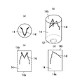
本発明が適用されたLED発光装置10について、図面を用いて説明する。図1および図2は実施例1で、LED発光装置10は、大略、面発光型のLED12と、レンズ14と、必要に応じて設けられるカバー16と、ベース18と、口金19と、給電手段20とで構成されている。   An LED light emitting device 10 to which the present invention is applied will be described with reference to the drawings. 1 and 2 show the first embodiment. The LED light-emitting device 10 is roughly composed of a surface-emitting LED 12, a lens 14, a cover 16 provided as necessary, a base 18, a base 19, and power supply means. 20.

LED12は、所定の電圧が印加されることによって光を放射する半導体素子であり、ベース18の図中上面中央に実装保持されている。LED12は、円盤状(もちろん、矩形であってもよい)の発光面12aで発光するタイプのものであり、その配光パターンはいわゆるランバーシアン型である。このランバーシアン型配光パターンでは、光軸(=0°)とその近傍にほとんどの光が集まっているのが特徴であり、当該光軸と成す角度が±30°の範囲内にLED12から放射される全光の50%が含まれており、±45°の範囲内には全光の70%が含まれており、さらに±60°の範囲内には全光の90%が含まれている。   The LED 12 is a semiconductor element that emits light when a predetermined voltage is applied, and is mounted and held at the center of the upper surface of the base 18 in the drawing. The LED 12 is of a type that emits light on a light emitting surface 12a having a disk shape (which may of course be rectangular), and its light distribution pattern is a so-called Lambertian type. This Lambertian light distribution pattern is characterized by the fact that most of the light is gathered at the optical axis (= 0 °) and its vicinity, and the angle formed with the optical axis is emitted from the LED 12 within a range of ± 30 °. 50% of the total light is included, 70% of the total light is included in the range of ± 45 °, and 90% of the total light is included in the range of ± 60 °. Yes.

レンズ14は、LED12から放射される光を受け入れる底面14aを有するガラス又は樹脂からなる透明中実体であり、その底面14aをLED12に対向させて(より厳密には、底面14aとLED12の発光面12aとを互いに平行にして)ベース18の図1中上面中央に取り付けられている。前記レンズ14は本実施例では六角柱で、その頂面14hに形成された凹穴14gはレンズ14の頂面14hに向かって次第に拡開する円錐又は円錐台である。また、レンズ14の底面周縁には、レンズ14をベース18の上面に当接固定するための脚部14eが図中下向きに突設されている。脚部14eは突起状のものを複数配置するようにしてもよいし、リング状にして底面14aの外周部分に配置するようにしてもよい。また、脚部14eはレンズ14と一体的のものであってもよいし、別体でもよい。もちろん、レンズ14において、脚部14eは、必須の構成要素ではなく、レンズ本体14cのみでレンズ14を構成してもよい。   The lens 14 is a transparent solid body made of glass or resin having a bottom surface 14 a that receives light emitted from the LED 12, and the bottom surface 14 a faces the LED 12 (more precisely, the bottom surface 14 a and the light emitting surface 12 a of the LED 12. Are attached to the center of the upper surface of the base 18 in FIG. The lens 14 is a hexagonal column in this embodiment, and the concave hole 14g formed in the top surface 14h is a cone or a truncated cone that gradually expands toward the top surface 14h of the lens 14. Further, a leg portion 14e is provided on the periphery of the bottom surface of the lens 14 so as to protrude downward in FIG. Plural leg portions 14e may be arranged, or may be arranged in a ring shape on the outer peripheral portion of the bottom surface 14a. Further, the leg portion 14e may be integral with the lens 14, or may be a separate body. Of course, in the lens 14, the leg portion 14 e is not an essential component, and the lens 14 may be configured only by the lens body 14 c.

また、光散乱用の凹穴14gの表面にサンドブラスト加工を施したり、レンズ14を形成する金型のキャビテイの凹穴14gを形成する部分を粗面(微細な凹凸面も含む)にし、これをレンズ14の凹穴14gの表面に転写することでレンズ14の凹穴14gの表面を粗面(微細な凹凸面も含む)にしてもよい。   Further, the surface of the concave hole 14g for light scattering is subjected to sandblasting, or the portion where the concave hole 14g of the mold cavity for forming the lens 14 is formed to be a rough surface (including a fine uneven surface). The surface of the concave hole 14g of the lens 14 may be roughened (including a fine uneven surface) by transferring it to the surface of the concave hole 14g of the lens 14.

カバー16は、必要に応じて設けられる部材であり、本実施例では、透明ガラスで形成された中空の略球状体がLED12およびレンズ14を内包するようにして、ベース18の上面に配設されている。なお、カバー16の形状は球状に限られず、砲弾型のような曲面体であってもよいし、複数の曲面あるいは平面を組み合わせて構成してもよい。また、材質についても透明ガラスに限られず、その他の透明体(樹脂)で構成してもよい。   The cover 16 is a member provided as necessary. In this embodiment, a hollow substantially spherical body formed of transparent glass is disposed on the upper surface of the base 18 so as to enclose the LED 12 and the lens 14. ing. The shape of the cover 16 is not limited to a spherical shape, and may be a curved body such as a shell shape, or may be configured by combining a plurality of curved surfaces or planes. Also, the material is not limited to transparent glass, but may be composed of other transparent bodies (resins).

ベース18は、LED12、レンズ14、およびカバー16を保持するとともに、外部からの電力をLED12に供給する給電手段20をその内部に収容する部材であり、上部ベース22と、下部ベース24とで構成されている。   The base 18 is a member that holds the LED 12, the lens 14, and the cover 16, and that houses a power supply unit 20 that supplies electric power from the outside to the LED 12, and includes an upper base 22 and a lower base 24. Has been.

上部ベース22は、金属(例えば、アルミニウム)やセラミック等の熱伝導および放熱に優れた材料で形成された有蓋円筒状体(もちろん、角筒状であってもよい。)であり、その天面22aには、LED12やカバー16を取り付けるための溝22bが形成されているとともに、その蓋部22cには、上部ベース22の内部空間22dと天面22a側とを連通する連通孔26が設けられている。   The upper base 22 is a covered cylindrical body (of course, may be a rectangular tube shape) formed of a material excellent in heat conduction and heat dissipation such as metal (for example, aluminum) or ceramic, and its top surface. A groove 22b for attaching the LED 12 and the cover 16 is formed in 22a, and a communication hole 26 is provided in the lid portion 22c to communicate the internal space 22d of the upper base 22 with the top surface 22a side. ing.

下部ベース24は、上部ベース22と同様に、セラミック等の絶縁体で形成されており、太径部24aと細径部24bとその間のテーパ部24cとで構成された異径柱状体である。また、太径部24aの外径は、上部ベース22の内径よりもやや小さく形成されており、当該太径部24aのほとんどが上部ベース22の底部に挿入固定されている(なお、本実施例では、上部ベース22と下部ベース24とはビス28で固定されているが、これに代えて接着剤等で固定してもよい。)。一方、細径部24bの外周面には、口金19に螺入させるためのネジが形成されている。さらに、下部ベース24には、太径部24aの上面からテーパ部24c内を経由して細径部24bの下面および側面に至る連通孔30が形成されており、後述するように、給電手段20の大部分が当該連通孔30に配設されている。   Similar to the upper base 22, the lower base 24 is formed of an insulating material such as ceramic, and is a different-diameter columnar body including a large diameter portion 24a, a small diameter portion 24b, and a tapered portion 24c therebetween. The outer diameter of the large diameter portion 24a is formed to be slightly smaller than the inner diameter of the upper base 22, and most of the large diameter portion 24a is inserted and fixed to the bottom of the upper base 22 (this embodiment) The upper base 22 and the lower base 24 are fixed with screws 28, but may be fixed with an adhesive or the like instead. On the other hand, a screw for screwing into the base 19 is formed on the outer peripheral surface of the small diameter portion 24b. Further, the lower base 24 is formed with a communication hole 30 extending from the upper surface of the large diameter portion 24a to the lower surface and the side surface of the small diameter portion 24b via the inside of the tapered portion 24c. Most of these are disposed in the communication hole 30.

口金19は、照明器具等のソケット(図示せず)に螺入される有底筒状体であり、ネジが形成された導電材料(例えば金属)製の側面部19aと、底面から突設する導電材料製突設部19bと、側面部19aおよび突設部19b間を電気的に絶縁する絶縁材料製の絶縁部19cとで構成されている。   The base 19 is a bottomed cylindrical body that is screwed into a socket (not shown) such as a lighting fixture, and protrudes from a side surface portion 19a made of a conductive material (for example, metal) on which a screw is formed, and from the bottom surface. The conductive material protruding portion 19b and the insulating portion 19c made of an insulating material that electrically insulates between the side surface portion 19a and the protruding portion 19b.

給電手段20は、口金19に供給された電力をLED12に供給するためのものであり、口金19に印加された電圧をLED12の駆動電圧まで変圧するとともに、LED12に対して過剰な電流が流れるのを防止する駆動回路20aと、口金19および駆動回路20a間を導通させる一対の入力側リード線20bと、駆動回路20aおよびLED12間を導通させる一対の出力側リード線20cとで構成されている。また、駆動回路20aは、下部ベース24の連通孔30における図中上端側に広く形成された部分に配設されており、入力側リード線20bは、当該連通孔30の図中下端側に配設されており、出力側リード線20cは、上部ベース22の蓋部22cに形成された連通孔26に挿通されている。   The power supply means 20 is for supplying the power supplied to the base 19 to the LED 12, transforms the voltage applied to the base 19 to the drive voltage of the LED 12, and an excessive current flows to the LED 12. The driving circuit 20a is configured to include a pair of input-side lead wires 20b that conducts between the base 19 and the driving circuit 20a, and a pair of output-side lead wires 20c that conducts between the driving circuit 20a and the LED 12. Further, the drive circuit 20a is disposed in a portion of the communication hole 30 of the lower base 24 that is widely formed on the upper end side in the figure, and the input side lead wire 20b is arranged on the lower end side of the communication hole 30 in the figure. The output-side lead wire 20 c is inserted into a communication hole 26 formed in the lid portion 22 c of the upper base 22.

このLEDランプ10は、一例を示せば以下の手順で製造される。上部ベース22の図中上表面にLED12を実装し、当該LED12に被せるようにレンズ14およびカバー16をこの順で接着剤等によって取り付け、給電手段20を内包するようにして上部ベース22の下端に下部ベース24を挿設してビス28で固定し、然る後、下部ベース24の下端部に口金19を取り付ける。   If this LED lamp 10 shows an example, it will be manufactured in the following procedures. The LED 12 is mounted on the upper surface of the upper base 22 in the figure, and the lens 14 and the cover 16 are attached with an adhesive or the like in this order so as to cover the LED 12, and the power supply means 20 is included at the lower end of the upper base 22. The lower base 24 is inserted and fixed with the screw 28, and then the base 19 is attached to the lower end portion of the lower base 24.

しかして、LED12を点灯すると、発光面12aから出た光はレンズ14の底面14aから内部に入り、乱反射して側面14b及び頂面14h、凹穴14gから出光するが、その際、凹穴14gの周囲やレンズ14の側面14bの稜線14fで強く光り、六角柱のレンズ14の側面14bに正対して(或いは正面から)見たときにあたかもM字状に張られた白熱電球のフィラメントが光っているような外観を呈する。LED12の出光色、レンズ14の色やカバー16の色を例えば従来の白熱電球の橙色にすることで、より従来の白熱電球に模することが出来、LEDランプ10でありながら従来の白熱電球のムードを醸し出すことができる。   When the LED 12 is turned on, the light emitted from the light emitting surface 12a enters the inside from the bottom surface 14a of the lens 14 and diffusely reflects and exits from the side surface 14b, the top surface 14h, and the concave hole 14g. And the ridgeline 14f of the side surface 14b of the lens 14 shines strongly, and the filament of the incandescent bulb stretched in an M shape shines when viewed from the side 14b of the hexagonal prism lens 14 (or from the front). Appears to look like. By making the light emission color of the LED 12, the color of the lens 14 and the color of the cover 16 orange, for example, a conventional incandescent light bulb, it can be more imitated by a conventional incandescent light bulb. You can create a mood.

レンズ14は、上記の場合、六角柱の場合を示したが、円柱、三角柱、四角柱或いはそれ以上の多角柱、或いは円錐台、三角錐台、四角錐台或いはそれ以上の多角錐台としてもよい。また、凹穴14gも上記同様、レンズ14の頂面14hに向かって次第に拡開する円錐、円錐台、三角錐、四角錐、或いはそれ以上の多角錐、更には三角錐台、四角錐台或いはそれ以上の多角錐台とすることも可能であり、レンズ14と凹穴14gとは上記形状のものを自由に組み合わせることができる。例えば、レンズ14を円柱又は円錐台とした場合、凹穴14gを円錐、円錐台又は多角錐或いは多角錐台としたり、レンズ14を多角錐台とした場合、凹穴14gを円錐、円錐台又は多角錐或いは多角錐台とすることができる。勿論、上記の組み合わせにおいては、発光状態について多少の違いはあるが、多様なフィラメントによる発光状態を模した発光が可能となる。なお、レンズ14を円錐台又は多角錐台とした場合、円錐台又は多角錐台の面積の広い方を頂面14h側としてもよいし、逆に底面14a側にしてもよい。   In the above case, the lens 14 is a hexagonal column, but the lens 14 may be a cylinder, a triangular column, a quadrangular column or more, or a truncated cone, a triangular frustum, a quadrangular pyramid or more. Good. Similarly to the above, the concave hole 14g also has a cone, a truncated cone, a triangular pyramid, a quadrangular pyramid, or a larger polygonal pyramid that gradually expands toward the top surface 14h of the lens 14, and further a triangular frustum, a quadrangular pyramid or More polygonal frustums can be used, and the lens 14 and the recessed hole 14g can be freely combined with the above-mentioned shapes. For example, when the lens 14 is a cylinder or a truncated cone, the concave hole 14g is a cone, a truncated cone or a polygonal pyramid or a polygonal truncated cone. It can be a polygonal pyramid or a polygonal frustum. Of course, in the above combination, although there are some differences in the light emission state, it is possible to emit light imitating the light emission state by various filaments. When the lens 14 is a truncated cone or a polygonal frustum, the larger area of the truncated cone or the polygonal frustum may be the top surface 14h side, or conversely, the bottom surface 14a side.

本発明の実施例2は、実施例1の凹穴14gに代えて線状に連続する点14iをレンズ14内に形成する場合である。この場合もレンズ14は、円柱、三角柱、四角柱或いはそれ以上の多角柱、或いは円錐台、三角錐台、四角錐台或いはそれ以上の多角錐台としてもよい。図の実施例では円柱を使用している。   The second embodiment of the present invention is a case where a linearly continuous point 14 i is formed in the lens 14 instead of the concave hole 14 g of the first embodiment. In this case as well, the lens 14 may be a cylinder, a triangular prism, a quadrangular prism or a polygonal prism, or a truncated cone, a triangular frustum, a quadrangular pyramid or a polygonal truncated cone. In the illustrated embodiment, a cylinder is used.

点14iはレンズ14の所定位置にレーザーを集光し、当該部分を過熱することで、レンズ14がガラスの場合には点状クラックを、樹脂の場合には泡を生じさせることで形成することになる。本実施例ではフィラメントの形状に合わせて、レンズ14の一正面から見た形状が略M字、平面から見た時に略V字形、側面から見た時に略逆レ字形となるように、線状に連続して形成することになる。勿論、点14iの連続体の形状はこれに限られるものでなく、様々なフィラメントに模して形成されることになる。   The point 14i is formed by condensing the laser at a predetermined position of the lens 14 and overheating the portion, thereby generating a point-like crack when the lens 14 is made of glass and generating bubbles when the lens 14 is made of resin. become. In this embodiment, in accordance with the shape of the filament, the shape of the lens 14 viewed from one front surface is approximately M-shaped, approximately V-shaped when viewed from the plane, and approximately linear when viewed from the side. It is formed continuously. Of course, the shape of the continuum of the points 14i is not limited to this, and is formed by imitating various filaments.

このように点14iの連続体が内部に形成されたレンズ14にLED12の光を入光させると、欠陥である点14iは連続に光り、あたかもフィラメントが光っているように見える。前述同様、LED12の出光色、レンズ14の色やカバー16の色を例えば従来の白熱電球の橙色にすることで、より従来の白熱電球に模することが出来、LEDランプ10でありながら従来の白熱電球のムードを醸し出すことができる。   When the light of the LED 12 is incident on the lens 14 in which the continuum of the points 14i is formed in this way, the point 14i which is a defect shines continuously, and it looks as if the filament is shining. As described above, the light emission color of the LED 12, the color of the lens 14, and the color of the cover 16 are changed to, for example, the orange color of a conventional incandescent light bulb. You can create the mood of an incandescent bulb.

なお、上記のように、凹穴14gの表面が粗面に形成されておれば、当該表面でより強い反射が得られればさらに前述の効果を強調することができる。   As described above, if the surface of the concave hole 14g is formed to be rough, the above-described effect can be further emphasized if stronger reflection is obtained on the surface.

10…LED発光装置,12…LED,12a…発光面,14…レンズ,14a…底面,14b…側面,14e…脚部,14f…稜線,14g…凹穴,14h…頂面,14i…点,16…カバー,18…ベース,19…口金,19a…側面部,19b…突設部,19c…絶縁部,20…給電手段,20a…駆動回路,20b…入力側リード線,20c…出力側リード線,22…上部ベース,22a…天面,22b…溝,22c…蓋部,22d…内部空間,24…下部ベース,24a…太径部,24b…細径部,24c…テーパ部,26…連通孔,28…ビス,30…連通孔。 DESCRIPTION OF SYMBOLS 10 ... LED light-emitting device, 12 ... LED, 12a ... Light emission surface, 14 ... Lens, 14a ... Bottom surface, 14b ... Side surface, 14e ... Leg part, 14f ... Ridge line, 14g ... Recessed hole, 14h ... Top surface, 14i ... Point, DESCRIPTION OF SYMBOLS 16 ... Cover, 18 ... Base, 19 ... Base, 19a ... Side surface part, 19b ... Projection part, 19c ... Insulation part, 20 ... Power supply means, 20a ... Drive circuit, 20b ... Input side lead wire, 20c ... Output side lead Line 22, upper base, 22 a, top surface, 22 b, groove, 22 c, lid portion, 22 d, internal space, 24, lower base, 24 a, large diameter portion, 24 b, small diameter portion, 24 c, taper portion, 26,. Communication hole, 28 ... screw, 30 ... communication hole.

Claims (4)

面発光型のLEDと、
前記LEDの発光面に対向する底面で前記LEDから放射される光を受け入れ、頂面に光散乱用の凹穴が形成された透明中実柱状のレンズと、
前記LEDに給電するための給電手段とを備えており、
前記レンズが円柱、多角柱、円錐台又は多角錐台に形成され、凹穴がレンズの頂面に向かって次第に拡開する円錐、円錐台、多角錐又は多角錐台であることを特徴とするLEDランプ。
Surface-emitting LEDs,
A transparent solid columnar lens in which light emitted from the LED is received at the bottom surface facing the light emitting surface of the LED, and a concave hole for light scattering is formed on the top surface;
Power supply means for supplying power to the LED,
The lens is formed in a cylinder, a polygonal column, a truncated cone, or a polygonal frustum, and the concave hole is a cone, a truncated cone, a polygonal pyramid, or a polygonal frustum that gradually expands toward the top surface of the lens. LED lamp.
請求項1のLEDランプにおいて、凹穴に代わる線状に連続する点がレンズ内に形成されていることを特徴とするLEDランプ。   2. The LED lamp according to claim 1, wherein a point that is continuous in a line instead of the recessed hole is formed in the lens. 請求項2のLEDランプにおいて、点の連続線がレンズの一正面から見て略M字形を描き、頂面から見て略V字形を描くように形成されていることを特徴とするLEDランプ。   3. The LED lamp according to claim 2, wherein the continuous line of dots draws a substantially M shape when viewed from one front surface of the lens and a substantially V shape when viewed from the top surface. 光散乱用の凹穴の表面が粗面に形成されていることを特徴とする請求項1〜3のいずれかに記載のLEDランプ。
The LED lamp according to any one of claims 1 to 3, wherein the surface of the concave hole for light scattering is formed into a rough surface.
JP2013031286A 2012-12-27 2013-02-20 LED lamp Pending JP2014143156A (en)

Priority Applications (2)

Application Number Priority Date Filing Date Title
JP2013031286A JP2014143156A (en) 2012-12-27 2013-02-20 LED lamp
CN201310740323.XA CN103899949A (en) 2012-12-27 2013-12-27 Led lamp

Applications Claiming Priority (3)

Application Number Priority Date Filing Date Title
JP2012285665 2012-12-27
JP2013031286A JP2014143156A (en) 2012-12-27 2013-02-20 LED lamp

Publications (1)

Publication Number Publication Date
JP2014143156A true JP2014143156A (en) 2014-08-07

Family

ID=51424287

Family Applications (1)

Application Number Title Priority Date Filing Date
JP2013031286A Pending JP2014143156A (en) 2012-12-27 2013-02-20 LED lamp

Country Status (1)

Country Link
JP (1) JP2014143156A (en)

Cited By (2)

* Cited by examiner, † Cited by third party
Publication number Priority date Publication date Assignee Title
US20220046769A1 (en) * 2015-06-10 2022-02-10 Zhejiang Super Lighting Electric Appliance Co., Ltd Led filament and led light bulb
US11892127B2 (en) 2014-09-28 2024-02-06 Zhejiang Super Lighting Electric Appliance Co., Ltd LED filament and LED bulb lamp

Cited By (2)

* Cited by examiner, † Cited by third party
Publication number Priority date Publication date Assignee Title
US11892127B2 (en) 2014-09-28 2024-02-06 Zhejiang Super Lighting Electric Appliance Co., Ltd LED filament and LED bulb lamp
US20220046769A1 (en) * 2015-06-10 2022-02-10 Zhejiang Super Lighting Electric Appliance Co., Ltd Led filament and led light bulb

Similar Documents

Publication Publication Date Title
JP4793649B2 (en) LED bulb and LED lighting apparatus
JP6145860B2 (en) Illumination light source and illumination device
JP5643670B2 (en) Luminous flux control member and lighting device
JP5850899B2 (en) Light emitting diode bulb
TWM474106U (en) Light emitting diode lamp
JP5717114B1 (en) Straight tube light emitting diode lighting
JP2010287343A (en) Light-emitting fixture
JP2012048950A (en) Lamp with base and lighting fixture
TWM457847U (en) Lighting device having a widely light emitting angle
JP2014143156A (en) LED lamp
CN202884577U (en) Light-emitting diode (LED) candle lamp
JP2015049970A (en) Led bulb and lighting device
US9410676B1 (en) LED light bulb
TW201326641A (en) LED bulb
TW201326655A (en) LED bulb
JP2011253901A (en) Led lighting device
TW201326646A (en) LED bulb
JP2014146570A (en) Lamp and illumination device
JP2013069884A (en) Illumination device
WO2017002960A1 (en) Illumination device
KR100902819B1 (en) Led light
JP3183249U (en) LED light emitting device
WO2017193536A1 (en) Led lamp bulb
JP3173027U (en) LED lights
JP6215177B2 (en) LED lamp and lens for LED lamp