JP2014142432A - Optical scanner and image forming apparatus - Google Patents
Optical scanner and image forming apparatus Download PDFInfo
- Publication number
- JP2014142432A JP2014142432A JP2013009742A JP2013009742A JP2014142432A JP 2014142432 A JP2014142432 A JP 2014142432A JP 2013009742 A JP2013009742 A JP 2013009742A JP 2013009742 A JP2013009742 A JP 2013009742A JP 2014142432 A JP2014142432 A JP 2014142432A
- Authority
- JP
- Japan
- Prior art keywords
- light beam
- light
- polygon mirror
- rotary polygon
- optical
- Prior art date
- Legal status (The legal status is an assumption and is not a legal conclusion. Google has not performed a legal analysis and makes no representation as to the accuracy of the status listed.)
- Pending
Links
Images


Landscapes
- Laser Beam Printer (AREA)
- Mechanical Optical Scanning Systems (AREA)
- Facsimile Scanning Arrangements (AREA)
Abstract
Description
本発明は、光走査装置及び画像形成装置に係り、更に詳しくは、被走査面を光によって走査する光走査装置、及び該光走査装置を備える画像形成装置に関する。 The present invention relates to an optical scanning device and an image forming apparatus, and more particularly to an optical scanning device that scans a surface to be scanned with light, and an image forming apparatus including the optical scanning device.
電子写真方式の画像記録では、レーザ光を用いた画像形成装置が広く用いられている。この画像形成装置は、一般的に光走査装置を備え、光偏向器(例えば、ポリゴンミラー)を用いて、感光性を有するドラムの表面をレーザ光で走査し、該ドラムの表面に潜像(静電潜像)を形成している。 In electrophotographic image recording, an image forming apparatus using a laser beam is widely used. This image forming apparatus generally includes an optical scanning device, and scans the surface of a photosensitive drum with a laser beam using an optical deflector (for example, a polygon mirror), and a latent image ( Electrostatic latent image).
そして、光走査装置は、1回の走査における書き込み開始前あるいは書き込み終了後の所定のタイミングで、光偏向器で偏向された光を受光する同期検知センサを備え、該同期検知センサの出力信号に基づいて1走査ラインにおける書き込み開始のタイミングを求めている。 The optical scanning device includes a synchronization detection sensor that receives the light deflected by the optical deflector at a predetermined timing before or after the end of writing in one scan, and outputs an output signal of the synchronization detection sensor. Based on this, the writing start timing in one scanning line is obtained.
例えば、特許文献1には、光源と、偏向器と、結像ミラーと、偏向器により偏向走査された光束を受光し光束が走査された位置を検出する検出部と、検出部に光束を導く検出用結像光学素子とを有する光走査装置において、検出用結像光学素子の有効径は入射光束直径よりも小さくし、検出用結像光学素子を介した後の光束の光強度分布は主光線を中心としたほぼ線対称の形状となることを特徴とする光走査装置が開示されている。
For example,
また、特許文献2には、光源から出射した光束を整形して主走査方向に長い線状の光束として結像させる第1の光学系と、第1の光学系の結像位置近傍に偏向面を有し、入射された光束を主走査方向に偏向走査する偏向手段と、偏向手段で反射偏向された光束を被走査面上に結像させると共に、偏向手段の偏向面と該被走査面とを略共役な関係とする第2の光学系と、偏向面の端部で反射偏向された光束を用いて被走査面上の走査開始位置のタイミングを制御する書き出し位置同期信号検出手段と、を有する走査光学装置において、偏向手段と書き出し位置同期信号検出手段との間の光路中に、偏向面の端部で反射偏向された光束のうち偏向面の端縁で反射偏向された部分のみを制限する光束制限手段を設けたことを特徴とする走査光学装置が開示されている。 Patent Document 2 discloses a first optical system that shapes a light beam emitted from a light source and forms an image as a linear light beam that is long in the main scanning direction, and a deflecting surface in the vicinity of the imaging position of the first optical system. And deflecting and scanning the incident light beam in the main scanning direction, and forming an image of the light beam reflected and deflected by the deflecting device on the surface to be scanned, and the deflection surface of the deflection unit and the surface to be scanned And a writing position synchronization signal detecting means for controlling the timing of the scanning start position on the surface to be scanned using a light beam reflected and deflected at the end of the deflecting surface. In the scanning optical device, the optical path between the deflecting means and the writing position synchronization signal detecting means limits only the portion of the light beam reflected and deflected at the end of the deflecting surface that is reflected and deflected at the end of the deflecting surface. Scanning optical device characterized by providing light beam limiting means It has been disclosed.
近年、情報機器の発展に伴い、スモールオフィス(小規模事務所)及びホームオフィスでのプリンタや複写機の需要が増加している。そして、それに伴って、画像形成装置の小型化への要求が高まってきた。そこで、画像形成装置の一部を構成する光走査装置に対しても小型化が重要となっている。 In recent years, with the development of information equipment, the demand for printers and copiers in small offices (small offices) and home offices has increased. Accordingly, there has been an increasing demand for downsizing of the image forming apparatus. Therefore, downsizing is also important for the optical scanning device constituting a part of the image forming apparatus.
しかしながら、特許文献1及び特許文献2に開示されている装置では、小型化と高い同期検知精度とを両立させるのは困難であった。
However, with the devices disclosed in
本発明は、光束によって被走査面を主走査方向に沿って走査する光走査装置であって、光源と、前記光源からの光束を整形するための開口を有する開口部材と、前記開口部材の開口を通過した光束が入射される回転多面鏡と、前記回転多面鏡で偏向された光束を前記被走査面に導光する走査光学系と、前記回転多面鏡で反射された光束が入射される受光器とを備え、前記回転多面鏡の回転軸に直交する平面に正射影したとき、前記回転多面鏡に入射する光束の幅は、前記回転多面鏡の1つの反射面の幅よりも小さく、前記開口部材の開口の前記主走査方向に直交する副走査方向に対応する方向に関する大きさが、前記主走査方向に対応する方向に関して、中央部よりも両端部で小さく、前記回転多面鏡の回転軸に直交する平面に正射影したとき、前記受光器に向かう光束の幅は、前記回転多面鏡に入射する光束の幅よりも小さい光走査装置である。 The present invention is an optical scanning device that scans a surface to be scanned along a main scanning direction with a light beam, and includes a light source, an opening member having an opening for shaping the light beam from the light source, and an opening of the opening member. A rotating polygon mirror that receives the light beam that has passed through, a scanning optical system that guides the light beam deflected by the rotating polygon mirror to the scanned surface, and a light receiving device that receives the light beam reflected by the rotating polygon mirror And when orthogonally projected onto a plane orthogonal to the rotation axis of the rotary polygon mirror, the width of the light beam incident on the rotary polygon mirror is smaller than the width of one reflecting surface of the rotary polygon mirror, The size of the aperture of the aperture member in the direction corresponding to the sub-scanning direction orthogonal to the main scanning direction is smaller at both ends than the center in the direction corresponding to the main scanning direction, and the rotation axis of the rotary polygon mirror Orthographically projected onto a plane perpendicular to , The width of the light beam toward the light receiver is a small optical scanning device than the width of the light beam incident on the rotating polygon mirror.
本発明の光走査装置によれば、同期検知精度を低下させることなく小型化を図ることができる。 According to the optical scanning device of the present invention, it is possible to reduce the size without reducing the synchronization detection accuracy.
以下、本発明の一実施形態を図1〜図19に基づいて説明する。図1には、一実施形態に係る画像形成装置としての複合機2000の概略構成が示されている。
Hereinafter, an embodiment of the present invention will be described with reference to FIGS. FIG. 1 shows a schematic configuration of a
この複合機2000は、複写機、プリンタ、及びファクシミリの機能を有し、本体装置1001、読取装置1002、及び自動原稿給紙装置1003などを備えている。
The
本体装置1001は、4色(ブラック、シアン、マゼンタ、イエロー)を重ね合わせてフルカラーの画像を形成するタンデム方式の多色カラープリンタであり、光走査装置2010、4つの感光体ドラム(2030a、2030b、2030c、2030d)、4つのクリーニングユニット(2031a、2031b、2031c、2031d)、4つの帯電装置(2032a、2032b、2032c、2032d)、4つの現像ローラ(2033a、2033b、2033c、2033d)、中間転写ベルト2040、転写ローラ2042、定着ローラ2050、給紙コロ2054、排紙ローラ2058、給紙トレイ2060、排紙トレイ2070、通信制御装置2080、及び上記各部を統括的に制御するプリンタ制御装置2090などを備えている。
The
読取装置1002は、本体装置1001の上側に配置され、原稿を読み取る。すなわち、読取装置1002は、いわゆるスキャナ装置である。ここで読み取られた原稿の画像情報は、本体装置1001のプリンタ制御装置2090に送られる。
The
自動原稿給紙装置1003は、読取装置1002の上側に配置され、セットされた原稿を読取装置1002に向けて送り出す。この自動原稿給紙装置1003は、一般にADF(Auto Document Feeder)と呼ばれている。
The
通信制御装置2080は、ネットワークなどを介した上位装置(例えばパソコン)との双方向の通信、及び公衆回線を介したデータ通信を制御する。
The
プリンタ制御装置2090は、CPU、該CPUにて解読可能なコードで記述されたプログラム及び該プログラムを実行する際に用いられる各種データが格納されているROM、作業用のメモリであるRAM、アナログデータをデジタルデータに変換するA/D変換回路などを有している。そして、プリンタ制御装置2090は、読取装置1002からの画像情報あるいは通信制御装置2080を介した画像情報を光走査装置2010に送る。
The
感光体ドラム2030a、帯電装置2032a、現像ローラ2033a、及びクリーニングユニット2031aは、組として使用され、ブラックの画像を形成する画像形成ステーション(以下では、便宜上「Kステーション」ともいう)を構成する。
The
感光体ドラム2030b、帯電装置2032b、現像ローラ2033b、及びクリーニングユニット2031bは、組として使用され、マゼンタの画像を形成する画像形成ステーション(以下では、便宜上「Mステーション」ともいう)を構成する。
The
感光体ドラム2030c、帯電装置2032c、現像ローラ2033c、及びクリーニングユニット2031cは、組として使用され、シアンの画像を形成する画像形成ステーション(以下では、便宜上「Cステーション」ともいう)を構成する。
The
感光体ドラム2030d、帯電装置2032d、現像ローラ2033d、及びクリーニングユニット2031dは、組として使用され、イエローの画像を形成する画像形成ステーション(以下では、便宜上「Yステーション」ともいう)を構成する。
The
各感光体ドラムはいずれも、その表面に感光層が形成されている。ここでは、各感光体ドラムの表面がそれぞれ被走査面である。各感光体ドラムは、不図示の回転機構により、図1における面内で矢印方向に回転する。 Each photosensitive drum has a photosensitive layer formed on the surface thereof. Here, the surface of each photosensitive drum is a surface to be scanned. Each photosensitive drum is rotated in the direction of the arrow in the plane of FIG. 1 by a rotation mechanism (not shown).
各帯電装置は、対応する感光体ドラムの表面をそれぞれ均一に帯電させる。 Each charging device uniformly charges the surface of the corresponding photosensitive drum.
光走査装置2010は、プリンタ制御装置2090からの多色の画像情報(ブラック画像情報、シアン画像情報、マゼンタ画像情報、イエロー画像情報)に基づいて色毎に変調された光により、対応する帯電された感光体ドラムの表面をそれぞれ走査する。これにより、画像情報に対応した潜像が各感光体ドラムの表面にそれぞれ形成される。すなわち、ここでは、各感光体ドラムが像担持体である。ここで形成された潜像は、感光体ドラムの回転に伴って対応する現像装置の方向に移動する。なお、この光走査装置2010の構成については後述する。
The
各現像ローラは、回転に伴って、対応するトナーカートリッジ(図示省略)からのトナーが、その表面に薄く均一に塗布される。そして、各現像ローラの表面のトナーは、対応する感光体ドラムの表面に接すると、該表面における光が照射された部分にだけ移行し、そこに付着する。すなわち、各現像ローラは、対応する感光体ドラムの表面に形成された潜像にトナーを付着させて顕像化させる。ここでトナーが付着した像(トナー画像)は、感光体ドラムの回転に伴って中間転写ベルト2040の方向に移動する。
As each developing roller rotates, toner from a corresponding toner cartridge (not shown) is thinly and uniformly applied to the surface thereof. Then, when the toner on the surface of each developing roller comes into contact with the surface of the corresponding photosensitive drum, the toner moves only to a portion irradiated with light on the surface and adheres to the surface. In other words, each developing roller causes toner to adhere to the latent image formed on the surface of the corresponding photosensitive drum so as to be visualized. Here, the toner-attached image (toner image) moves in the direction of the
イエロー、マゼンタ、シアン、ブラックの各トナー画像は、所定のタイミングで中間転写ベルト2040上に順次転写され、重ね合わされてカラー画像が形成される。
The yellow, magenta, cyan, and black toner images are sequentially transferred onto the
給紙トレイ2060には記録紙が格納されている。この給紙トレイ2060の近傍には給紙コロ2054が配置されており、該給紙コロ2054は、記録紙を給紙トレイ2060から1枚ずつ取り出す。該記録紙は、所定のタイミングで中間転写ベルト2040と転写ローラ2042との間隙に向けて送り出される。これにより、中間転写ベルト2040上のカラー画像が記録紙に転写される。カラー画像が転写された記録紙は、定着ローラ2050に送られる。
Recording paper is stored in the
定着ローラ2050では、熱と圧力とが記録紙に加えられ、これによってトナーが記録紙上に定着される。トナーが定着された記録紙は、排紙ローラ2058を介して排紙トレイ2070に送られ、排紙トレイ2070上に順次積み重ねられる。
In the fixing
各クリーニングユニットは、対応する感光体ドラムの表面に残ったトナー(残留トナー)を除去する。残留トナーが除去された感光体ドラムの表面は、再度対応する帯電装置に対向する位置に戻る。 Each cleaning unit removes toner (residual toner) remaining on the surface of the corresponding photosensitive drum. The surface of the photosensitive drum from which the residual toner has been removed returns to the position facing the corresponding charging device again.
次に、前記光走査装置2010の構成について説明する。
Next, the configuration of the
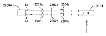
光走査装置2010は、一例として図2〜図5に示されるように、2つの光源(2200A、2200B)、4つのカップリングレンズ(2201a、2201b、2201c、2201d)、4つの開口板(2202a、2202b、2202c、2202d)、4つのシリンドリカルレンズ(2204a、2204b、2204c、2204d)、光偏向器2104、4つの走査レンズ(2105a、2105b、2105c、2105d)、8枚の折り返しミラー(2106A、2106B、2107a、2107b、2107c、2107d、2108a、2108d)、同期検知光学系11、同期検知センサ12、遮光板13、及び不図示の走査制御装置などを備えている。そして、これらは、光学ハウジング2300の所定位置に組み付けられている。
2 to 5 as an example, the
なお、ここでは、XYZ3次元直交座標系において、各感光体ドラムの長手方向(回転軸方向)に沿った方向をY軸方向、光偏向器2104の回転軸に沿った方向をZ軸方向として説明する。また、以下では、便宜上、各光学部材において、主走査方向に対応する方向を「主走査対応方向」と略述し、副走査方向に対応する方向を「副走査対応方向」と略述する。
Here, in the XYZ three-dimensional orthogonal coordinate system, the direction along the longitudinal direction (rotation axis direction) of each photosensitive drum is defined as the Y-axis direction, and the direction along the rotation axis of the
光源2200Aと光源2200Bは、X軸方向に関して離れた位置に配置されている。各光源は、いずれも2つの発光部を有しており、少なくともZ軸方向に関して離間している2つの光束を射出する。
The
ここでは、光源2200Aから射出される2つの光束のうち、+Z側の光束を「光束La」といい、−Z側の光束を「光束Lb」という。また、光源2200Bから射出される2つの光束のうち、+Z側の光束を「光束Ld」といい、−Z側の光束を「光束Lc」という。
Here, of the two light beams emitted from the
カップリングレンズ2201aは、光源2200Aから射出された光束Laの光路上に配置され、該光束を略平行光束とする。
The
カップリングレンズ2201bは、光源2200Aから射出された光束Lbの光路上に配置され、該光束を略平行光束とする。
The
カップリングレンズ2201cは、光源2200Bから射出された光束Lcの光路上に配置され、該光束を略平行光束とする。
The
カップリングレンズ2201dは、光源2200Bから射出された光束Ldの光路上に配置され、該光束を略平行光束とする。
The
開口板2202aは、開口部を有し、カップリングレンズ2201aを介した光束Laを整形する。
The
開口板2202bは、開口部を有し、カップリングレンズ2201bを介した光束Lbを整形する。
The
開口板2202cは、開口部を有し、カップリングレンズ2201cを介した光束Lcを整形する。
The
開口板2202dは、開口部を有し、カップリングレンズ2201dを介した光束Ldを整形する。
The
なお、4つの開口板を区別する必要がないときは、それらを総称して「開口板2202」と表記する。
When it is not necessary to distinguish the four aperture plates, they are collectively referred to as “
シリンドリカルレンズ2204aは、開口板2202aの開口部を通過した光束Laの光路上に配置され、該光束をZ軸方向に関して集光する。
The
シリンドリカルレンズ2204bは、開口板2202bの開口部を通過した光束Lbの光路上に配置され、該光束をZ軸方向に関して集光する。
The
シリンドリカルレンズ2204cは、開口板2202cの開口部を通過した光束Lcの光路上に配置され、該光束をZ軸方向に関して集光する。
The
シリンドリカルレンズ2204dは、開口板2202dの開口部を通過した光束Ldの光路上に配置され、該光束をZ軸方向に関して集光する。
The
各光源と光偏向器2104との間の光路上に配置されている光学系は、「偏向器前光学系」とも呼ばれている。
The optical system disposed on the optical path between each light source and the
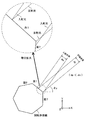
光偏向器2104は、2段構造の回転多面鏡を有している。各回転多面鏡には7つの鏡面がそれぞれ形成されており、各鏡面が偏向反射面である。そして、1段目(下段)の回転多面鏡では、シリンドリカルレンズ2204bを介した光束Lb及びシリンドリカルレンズ2204cを介した光束Lcがそれぞれ偏向され、2段目(上段)の回転多面鏡では、シリンドリカルレンズ2204aを介した光束La及びシリンドリカルレンズ2204dを介した光束Ldがそれぞれ偏向されるように配置されている。各回転多面鏡の内接円半径A(図6参照)は16mmである。
The
ここでは、光束La及び光束Lbは光偏向器2104の+X側に偏向され、光束Lc及び光束Ldは光偏向器2104の−X側に偏向される。
Here, the light beam La and the light beam Lb are deflected to the + X side of the
走査レンズ2105a及び走査レンズ2105bは、光偏向器2104の+X側に配置され、走査レンズ2105c及び走査レンズ2105dは、光偏向器2104の−X側に配置されている。
The
そして、走査レンズ2105aと走査レンズ2105bはZ軸方向に積層され、走査レンズ2105aは2段目の回転多面鏡に対向し、走査レンズ2105bは1段目の回転多面鏡に対向している。また、走査レンズ2105cと走査レンズ2105dはZ軸方向に積層され、走査レンズ2105cは1段目の回転多面鏡に対向し、走査レンズ2105dは2段目の回転多面鏡に対向している。
The
光偏向器2104で偏向された光束Laは、走査レンズ2105a、折り返しミラー2106A、折り返しミラー2107a、及び折り返しミラー2108aを介して、感光体ドラム2030aに照射される。
The light beam La deflected by the
光偏向器2104で偏向された光束Lbは、走査レンズ2105b、折り返しミラー2106A、及び折り返しミラー2107bを介して、感光体ドラム2030bに照射される。
The light beam Lb deflected by the
光偏向器2104で偏向された光束Lcは、走査レンズ2105c、折り返しミラー2106B、及び折り返しミラー2107cを介して、感光体ドラム2030cに照射される。
The light beam Lc deflected by the
光偏向器2104で偏向された光束Ldは、走査レンズ2105d、折り返しミラー2106B、折り返しミラー2107d、及び折り返しミラー2108dを介して、感光体ドラム2030dに照射される。
The light beam Ld deflected by the
各感光体ドラム上の光スポットは、対応する回転多面鏡の回転に伴って該感光体ドラムの長手方向に移動する。このときの光スポットの移動方向が「主走査方向」であり、感光体ドラムの回転方向が「副走査方向」である。 The light spot on each photoconductive drum moves in the longitudinal direction of the photoconductive drum as the corresponding rotary polygon mirror rotates. The moving direction of the light spot at this time is the “main scanning direction”, and the rotation direction of the photosensitive drum is the “sub scanning direction”.
光偏向器2104と各感光体ドラムとの間の光路上に配置されている光学系は、「走査光学系」とも呼ばれている。
The optical system disposed on the optical path between the
同期検知センサ12は、1回の走査における書き込み開始前あるいは書き込み終了後の所定のタイミングで、光偏向器2104で偏向された光束が入射する位置に配置されている。同期検知センサ12は、受光量に対応したレベルの信号(光電変換信号)を走査制御装置に出力する。走査制御装置は、同期検知センサ12の出力信号に基づいて、各感光体ドラムでの書き込み開始タイミングを求める。
The
同期検知光学系11は、光偏向器2104と同期検知センサ12との間に配置され、光偏向器2104で偏向された光束を同期検知センサ12に導光する。主走査対応方向に関して、同期検知光学系11の焦点距離は、走査光学系の焦点距離よりも短くなるように設定されている。この場合、同期検知センサ12の受光面上での光スポットの移動速度は、被走査面上での光スポットの移動速度よりも遅くなり、同期検知センサ12の出力信号におけるS/Nを高くすることができる。なお、同期検知光学系11は、1つの光学素子で構成されても良いし、複数の光学素子で構成されても良い。
The synchronization detection optical system 11 is disposed between the
また、同期検知光学系11の光利用効率は、走査光学系の光利用効率よりも高くなるように設定されている。この場合、同期検知センサ12の出力信号におけるS/Nを更に高くすることができる。
The light use efficiency of the synchronization detection optical system 11 is set to be higher than the light use efficiency of the scanning optical system. In this case, the S / N in the output signal of the
遮光板13は、光偏向器2104と同期検知光学系11との間に配置され、光偏向器2104で偏向された光束の主走査対応方向に関する一側端部を遮光する。
The
図7に示されるように、Z軸方向に直交する平面に正射影したとき、光源から射出され、光偏向器2104に入射する光束の進行方向とX軸方向とのなす角をθinと表記する。ここでは、θin=55°となるように設定されている。
As shown in FIG. 7, when orthogonally projected onto a plane orthogonal to the Z-axis direction, an angle formed between the traveling direction of the light beam emitted from the light source and incident on the
また、図8に示されるように、Z軸方向に直交する平面に正射影したとき、開口板の開口部を通過した光束の幅をdinと表記する。この光束が光偏向器2104に入射する。ここでは、din=4mmとなるように設定されている。dinは、1つの偏向反射面の幅(主走査対応方向に関する長さ)よりも小さい。
Further, as shown in FIG. 8, the width of the light beam that has passed through the opening of the aperture plate when orthogonally projected onto a plane orthogonal to the Z-axis direction is denoted as din. This light beam enters the
また、図9に示されるように、Z軸方向に直交する平面に正射影したとき、光偏向器2104で偏向され同期検知センサ12に向かう光束の進行方向とX軸方向とのなす角をθpと表記する。ここでは、θp=45°となるように設定されている。
Further, as shown in FIG. 9, when orthogonally projected onto a plane orthogonal to the Z-axis direction, the angle between the traveling direction of the light beam deflected by the
また、各回転多面鏡において、7つの偏向反射面を区別する必要があるときは、図10に示されるように、反時計まわりに面1、面2、面3、面4、面5、面6、面7とする。
Further, when it is necessary to distinguish the seven deflecting reflecting surfaces in each rotary polygon mirror, as shown in FIG. 10,
次に、光源2200Aから射出され、光偏向器2104に入射する光束(以下では、「入射光束」と略述する)と、光偏向器2104で偏向され、同期検知センサ12に向かう光束(以下では、「同期光束」と略述する)について説明する。ここでは、回転多面鏡の面1で反射された光束が、同期検知センサ12に向かうものとする。
Next, a light beam emitted from the
図11には、面1で反射された光束が、同期検知センサ12に向かうタイミングでの、入射光束及び同期光束が示されている。このとき、入射光束の全てが回転多面鏡の面1に入射するのではなく、入射光束の一部は面7に入射するように設定されている。そこで、Z軸方向に直交する平面に正射影したとき、同期光束の幅dpは、入射光束の幅dinよりも小さくなる。すなわち、このとき、光偏向器2104では、入射光束の一側端部が除かれて同期光束となる。なお、以下では、入射光束の一部が除かれることを「ケラレ」るともいう。
FIG. 11 shows the incident light beam and the synchronous light beam at the timing when the light beam reflected by the
ここでは、遮光板13は、同期光束に含まれる、面1における面7との境界近傍で反射された光束が遮光されるように配置されている。すなわち、遮光板13は、同期光束における上記「ケラレ」た側を制限する。
Here, the
続いて、光偏向器2104で偏向され、対応する感光体ドラムの走査領域に向かう光束(以下では、「走査光束」と略述する)について説明する。
Subsequently, a light beam deflected by the
図12には、走査光束が走査領域における走査開始位置に向かうタイミングでの、入射光束及び反射光束が示されている。このとき、入射光束の全てが回転多面鏡の面1に入射するのではなく、入射光束の一部は面7に入射するように設定されている。そこで、主走査対応方向に関して、走査開始位置に向かう走査光束の幅dsは、入射光束の幅dinよりも小さくなる。すなわち、このとき、光偏向器2104では、入射光束の一部が「ケラレ」ることとなる。また、走査開始位置に向かう走査光束の進行方向とX軸方向とのなす角θsは36°である。
FIG. 12 shows the incident light beam and the reflected light beam at the timing when the scanning light beam moves toward the scanning start position in the scanning region. At this time, not all of the incident light beam is incident on the
図13には、走査光束が走査領域の中央位置に向かうタイミングでの、入射光束及び反射光束が示されている。このとき、入射光束の全てが回転多面鏡の面1に入射する。そこで、主走査対応方向に関して、走査領域の中央位置に向かう走査光束の幅dcは、入射光束の幅dinと同じである。すなわち、このとき、光偏向器2104では、入射光束の「ケラレ」はない。
FIG. 13 shows the incident light beam and the reflected light beam at the timing when the scanning light beam is directed toward the center position of the scanning region. At this time, all of the incident light beam enters the
図14には、走査光束が走査領域における走査終了位置に向かうタイミングでの、入射光束及び反射光束が示されている。このとき、入射光束の全てが回転多面鏡の面1に入射するのではなく、入射光束の一部は面2に入射するように設定されている。そこで、主走査対応方向に関して、走査終了位置に向かう走査光束の幅deは、入射光束の幅dinよりも小さくなる。すなわち、このとき、光偏向器2104では、入射光束の一部が「ケラレ」ることとなる。また、走査終了位置に向かう走査光束の進行方向とX軸方向とのなす角θeは−36°である。
FIG. 14 shows the incident light beam and the reflected light beam at the timing when the scanning light beam moves toward the scanning end position in the scanning region. At this time, not all of the incident light beam is incident on the
|θs|+|θe|は、いわゆる走査画角に対応する角度であり、ここでは72°である。また、|θs|及び|θe|は、「走査半画角」と呼ばれている。 | Θs | + | θe | is an angle corresponding to a so-called scanning angle of view, and is 72 ° here. Further, | θs | and | θe | are called “scanning half angle of view”.
ここでは、感光体ドラムの走査領域における走査開始位置は、主走査方向に関する該走査領域の一側端部であり、感光体ドラムの走査領域における走査終了位置は、主走査方向に関する該走査領域の他側端部である。 Here, the scanning start position in the scanning area of the photosensitive drum is one side end of the scanning area in the main scanning direction, and the scanning end position in the scanning area of the photosensitive drum is in the scanning area in the main scanning direction. It is the other end.
走査制御装置は、同期光束の光量が走査光束の光量よりも大きくなるように、光偏向器2104で偏向された光束が同期検知センサ12に向かうタイミングの直前に光源の光出力を通常よりも高くし、同期検知直後に光源の光出力を通常に戻す処理を行う。これにより、同期検知センサ12の出力信号におけるS/Nを更に高くすることができる。
The scanning control device increases the light output of the light source higher than usual just before the timing when the light beam deflected by the
なお、光源2200Bから射出された光束についても、入射光束と走査光束の関係が上述した光源2200Aから射出された光束の場合と同じように設定されている。
For the light beam emitted from the
ところで、光偏向器にレーザ光を入射させる方式として、アンダーフィルドタイプとオーバーフィルドタイプがある。以下では、便宜上、アンダーフィルドタイプを「UFタイプ」、オーバーフィルドタイプを「OFタイプ」ともいう。 By the way, there are an underfilled type and an overfilled type as a method of making a laser beam incident on an optical deflector. Hereinafter, for convenience, the underfilled type is also referred to as “UF type” and the overfilled type is also referred to as “OF type”.
UFタイプでは、主走査対応方向に関して、1つの偏向反射面の長さよりも入射光の幅が小さい(例えば、特開2005−92129号参照)。この場合、入射光のすべてが1つの偏向反射面で反射される。 In the UF type, the width of incident light is smaller than the length of one deflecting / reflecting surface in the main scanning direction (see, for example, JP-A-2005-92129). In this case, all of the incident light is reflected by one deflecting reflection surface.
OFタイプでは、主走査対応方向に関して、1つの偏向反射面の長さよりも入射光の幅が大きい(例えば、特開平10−206778号参照)。この場合、入射光は同時に複数の偏向反射面に入射する。 In the OF type, the width of incident light is larger than the length of one deflecting / reflecting surface in the main scanning correspondence direction (see, for example, JP-A-10-206778). In this case, incident light is simultaneously incident on a plurality of deflecting and reflecting surfaces.
従来のUFタイプの光走査装置では、画像形成の高速化や画素密度の高密度化に対応するには、主走査対応方向に関して、1つの偏向反射面の長さを大きくする必要があるため、回転多面鏡における鏡面の数を少なくするか、回転多面鏡における内接円半径を大きくする必要があった。 In the conventional UF type optical scanning device, in order to cope with high-speed image formation and high pixel density, it is necessary to increase the length of one deflecting reflection surface in the main scanning-corresponding direction. It was necessary to reduce the number of mirror surfaces in the rotating polygon mirror or increase the inscribed circle radius in the rotating polygon mirror.
しかしながら、回転多面鏡における鏡面の数を少なくすると、該回転多面鏡の回転数を大きくしなければならない不都合があった。一方、回転多面鏡における内接円半径を大きくすると、回転多面鏡の風損が増加し、消費電力が増加するという不都合があった。なお、光源における発光部の数を増やし1つの偏向反射面で偏向されるビーム数を多くすることが考えられるが、発光部の数の増加とともに光源の駆動回路も大型化し、高コスト化を招く。 However, if the number of mirror surfaces in the rotating polygon mirror is reduced, there is a disadvantage that the number of rotations of the rotating polygon mirror must be increased. On the other hand, when the inscribed circle radius in the rotary polygon mirror is increased, there is a disadvantage that the windage loss of the rotary polygon mirror increases and the power consumption increases. Although it is conceivable to increase the number of light emitting units in the light source and increase the number of beams deflected by one deflecting reflection surface, the drive circuit of the light source increases in size and increases in cost as the number of light emitting units increases. .
また、従来のOFタイプの光走査装置では、画像形成の高速化や画素密度の高密度化に対応するには、鏡面の数が10以上の回転多面鏡を用いる必要があるため、走査画角が小さくなり、光走査装置の大型化を招くという不都合があった。また、光束の一部が利用されないため、光利用効率が低いという不都合があった。 Further, in the conventional OF type optical scanning device, it is necessary to use a rotating polygonal mirror having 10 or more mirror surfaces in order to cope with high-speed image formation and high pixel density. However, there is a disadvantage that the size of the optical scanning device is increased. Further, since a part of the light beam is not used, there is a disadvantage that the light use efficiency is low.
本実施形態では、光偏向器2104で偏向された光束が走査領域を走査する際、走査開始位置に向かうタイミング及び走査終了位置に向かうタイミングでのみ、入射光束の一部が光偏向器2104で「ケラレ」るように設定されている。
In the present embodiment, when the light beam deflected by the
そこで、本実施形態における光走査装置2010では、従来のUFタイプの光走査装置よりも、回転多面鏡を小型化することができる。この場合、消費電力を増加させることなく、回転多面鏡を高速で回転させることが可能となる。また、発光部の数を増加させる必要はなく、光源の駆動回路の大型化を避けることができる。そのため、高コスト化を招くことなく、画像形成の高速化や画素密度の高密度化に対応することができる。
Therefore, in the
例えば、内接円半径が18mmで6鏡面を有する回転多面鏡に代えて、内接円半径が16mmで7鏡面を有する回転多面鏡を用いることができる。この場合、風損が同じであれば、走査速度を約1.5(≒(18/16)2×(7/6))倍にすることが可能である。 For example, instead of a rotating polygon mirror having an inscribed circle radius of 18 mm and having 6 mirror surfaces, a rotating polygon mirror having an inscribed circle radius of 16 mm and having 7 mirror surfaces can be used. In this case, if the windage loss is the same, the scanning speed can be increased by about 1.5 (≈ (18/16) 2 × (7/6)) times.
なお、回転多面鏡の回転速度が同じでよければ、回転多面鏡の小型化により、回転多面鏡の耐久性を向上させるとともに、発熱量を低減させることができる。 If the rotational speed of the rotary polygon mirror is the same, the size of the rotary polygon mirror can be reduced, so that the durability of the rotary polygon mirror can be improved and the amount of heat generated can be reduced.
また、本実施形態における光走査装置2010では、従来のOFタイプの光走査装置よりも、走査画角を大きくすることができる。そのため、大型化を招くことなく、画像形成の高速化や画素密度の高密度化に対応することができる。
Further, in the
また、本実施形態では、同期光束は、入射光束の一部が光偏向器で「ケラレ」た光束である。この場合は、回転多面鏡の小型化を更に図ることができる。 In this embodiment, the synchronous light beam is a light beam in which a part of the incident light beam is “vignetted” by the optical deflector. In this case, it is possible to further reduce the size of the rotary polygon mirror.
ところで、従来の光走査装置では、入射光束の一部が光偏向器で「ケラレ」た光束を同期光束にすると、回転多面鏡における回転中心から各鏡面までの距離のばらつきや、隣接する2つの鏡面のなす角度のばらつきなどに起因して、同期光束の光量が鏡面毎に大きく異なる場合があった(図15参照)。図15におけるΔp0は、面1で反射された同期光束のピーク光量と面2で反射された同期光束のピーク光量との差分である。
By the way, in the conventional optical scanning device, when a part of the incident light beam is “sparkled” by the optical deflector as a synchronous light beam, variations in the distance from the rotation center to each mirror surface in the rotary polygon mirror, two adjacent Due to variations in the angles formed by the mirror surfaces, the amount of the synchronized light beam may vary greatly from mirror surface to mirror surface (see FIG. 15). Δp 0 in FIG. 15 is a difference between the peak light amount of the synchronous light beam reflected by the
本実施形態では、開口板2202及び遮光板13によって、回転中心から各鏡面までの距離にばらつきがあったり、隣接する2つの鏡面のなす角度にばらつきがあっても、同期光束の光量が鏡面毎に異なるのを抑制している。
In the present embodiment, even if the distance from the center of rotation to each mirror surface varies due to the
図16(A)には、従来のUFタイプの光走査装置で用いられている開口板の例が示されている。この開口板の開口部は矩形形状である。図16(B)には、従来のOFタイプの光走査装置で用いられている開口板の例が示されている。この開口板の開口部は、副走査対応方向に関する長さ(開口幅)が、主走査対応方向における両端部分で、主走査対応方向における中央部分よりも大きくなる形状を有している。 FIG. 16A shows an example of an aperture plate used in a conventional UF type optical scanning device. The opening of the opening plate has a rectangular shape. FIG. 16B shows an example of an aperture plate used in a conventional OF type optical scanning device. The opening of the aperture plate has a shape in which the length (opening width) in the sub-scanning corresponding direction is larger at both end portions in the main scanning corresponding direction than the central portion in the main scanning corresponding direction.
図17(A)〜図17(D)には、本実施形態における開口板2202の例が示されている。開口板2202の開口部は、副走査対応方向に関する長さ(開口幅)が、主走査対応方向における両端部分で、主走査対応方向における中央部分よりも小さくなる形状を有している。
FIGS. 17A to 17D show examples of the
図18には、本実施形態における同期光束の光量分布の一例が示されている。この場合は、回転多面鏡において、回転中心から各鏡面までの距離にばらつきがあったり、隣接する2つの鏡面のなす角度にばらつきがあっても、同期光束の光量が鏡面毎に異なるのを抑制することができる。図18におけるΔp1は、面1で反射された同期光束のピーク光量と面2で反射された同期光束のピーク光量との差分であり、上記Δp0よりも極めて小さい。
FIG. 18 shows an example of the light amount distribution of the synchronous light beam in the present embodiment. In this case, in the rotating polygon mirror, even if the distance from the center of rotation to each mirror surface varies or the angle formed by two adjacent mirror surfaces varies, it is possible to prevent the amount of synchronized light flux from being different for each mirror surface. can do. Δp1 in FIG. 18 is a difference between the peak light amount of the synchronous light beam reflected by the
図19には、本実施形態において、遮光板13を取り除いたときの同期光束の光量分布の一例が示されている。図19におけるΔp2は、面1で反射された同期光束のピーク光量と面2で反射された同期光束のピーク光量との差分であり、上記Δp1よりは大きいが、上記Δp0よりはかなり小さい。
FIG. 19 shows an example of the light quantity distribution of the synchronized light beam when the
以上の説明から明らかなように、本実施形態に係る光走査装置2010では、開口板2202によって本発明の開口部材が構成され、同期検知センサ12によって受光器が構成されている。また、遮光板13によって制限部材が構成され、同期検知光学系11によって受光光学系が構成されている。
As is clear from the above description, in the
以上説明したように、本実施形態に係る光走査装置2010によると、2つの光源(2200A、2200B)、4つの偏向器前光学系、光偏向器2104、4つ走査光学系、同期検知光学系11、同期検知センサ12、遮光板13、及び走査制御装置などを備えている。
As described above, according to the
各偏向器前光学系は、光源から射出された光束を整形する開口板2202を有している。該開口板2202の開口部は、副走査対応方向に関する開口幅が、主走査対応方向に関して中央部よりも両端部のほうが小さい形状である。
Each pre-deflector optical system has an
また、本実施形態では、光偏向器2104の回転軸に直交する平面に正射影したとき、光偏向器2104に入射する光束の幅dinは、光偏向器2104の1つの偏向反射面の幅(主走査対応方向に関する長さ)よりも小さい。
Further, in this embodiment, when orthogonal projection is performed on a plane orthogonal to the rotation axis of the
また、本実施形態では、光偏向器2104で偏向された光束が同期検知センサ12に向かうタイミングでは、入射光束の一部が光偏向器2104で「ケラレ」るように設定されている。
In the present embodiment, at the timing when the light beam deflected by the
また、本実施形態では、光偏向器2104で偏向された光束が走査領域を走査する際、走査開始位置に向かうタイミング及び走査終了位置に向かうタイミングでのみ、入射光束の一部が光偏向器2104で「ケラレ」るように設定されている。
Further, in the present embodiment, when the light beam deflected by the
また、本実施形態では、同期光束における「ケラレ」た側を制限する遮光板13を備えている。
In the present embodiment, the
また、本実施形態では、光偏向器2104の回転軸に直交する平面に正射影したとき、同期検知センサ12に向かう光束と光偏向器2104に入射する光束とのなす角度は、走査領域に向かう光束と光偏向器2104に入射する光束とのなす角度よりも小さい。
Further, in this embodiment, when orthogonal projection is performed on a plane orthogonal to the rotation axis of the
この場合、(1)回転多面鏡を小さくすることができ、(2)走査画角を大きくすることができ、(3)同期光束の光量が鏡面毎に異なるのを抑制することができる。そこで、同期検知精度を低下させることなく、光走査装置の小型化を図ることができる。 In this case, (1) the rotating polygon mirror can be reduced, (2) the scanning angle of view can be increased, and (3) it is possible to suppress the amount of the synchronous light flux from being different for each mirror surface. Therefore, it is possible to reduce the size of the optical scanning device without reducing the synchronization detection accuracy.
また、本実施形態では、主走査対応方向に関して、同期検知光学系11の焦点距離は走査光学系の焦点距離よりも短い。また、同期検知光学系11の光利用効率は走査光学系の光利用効率よりも大きい。また、光偏向器2104で偏向された光束が同期検知センサ12に向かうタイミングでの光源の光出力は、光偏向器2104で偏向された光束が走査領域に向かうタイミングでの光源の光出力よりも大きい。
In the present embodiment, the focal length of the synchronization detection optical system 11 is shorter than the focal length of the scanning optical system in the main scanning corresponding direction. Further, the light use efficiency of the synchronization detection optical system 11 is larger than the light use efficiency of the scanning optical system. The light output of the light source at the timing when the light beam deflected by the
この場合は、同期検知精度を更に向上させることができる。 In this case, the synchronization detection accuracy can be further improved.
そして、複合機2000は、光走査装置2010を備えているため、結果として、画像品質を低下させることなく、小型化を図ることができる。
Since the
なお、上記実施形態では、dinが4mmの場合について説明したがこれに限定されるものではない。 In the above embodiment, the case where din is 4 mm has been described, but the present invention is not limited to this.
また、上記実施形態では、θinが55°の場合について説明したがこれに限定されるものではない。 In the above embodiment, the case where θin is 55 ° has been described. However, the present invention is not limited to this.
また、上記実施形態では、θpが45°の場合について説明したがこれに限定されるものではない。 Moreover, although the said embodiment demonstrated the case where (theta) p was 45 degrees, it is not limited to this.
また、上記実施形態では、各回転多面鏡に内接する円の半径が16mmの場合について説明したがこれに限定されるものではない。 Moreover, although the said embodiment demonstrated the case where the radius of the circle | round | yen inscribed to each rotary polygon mirror was 16 mm, it is not limited to this.
また、上記実施形態では、各回転多面鏡に7面の鏡面が形成されている場合について説明したがこれに限定されるものではない。 Moreover, although the said embodiment demonstrated the case where the mirror surface of 7 surfaces was formed in each rotary polygon mirror, it is not limited to this.
また、上記実施形態において、光偏向器2104で偏向された光束が走査領域を走査する際、走査開始位置に向かうタイミング及び走査終了位置に向かうタイミングのいずれかでのみ、入射光束の一部が光偏向器2104で「ケラレ」るように設定されていても良い。
In the above embodiment, when the light beam deflected by the
また、上記実施形態において、光源にモノリシックな端面発光レーザアレイや面発光レーザアレイを用いても良い。 In the above embodiment, a monolithic edge emitting laser array or a surface emitting laser array may be used as the light source.
また、上記実施形態では、それぞれ2つの発光部を有する2つの光源が用いられる場合について説明したが、これに限定されるものではない。例えば、それぞれ1つの発光部を有する4つの光源を用いても良い。また、それぞれ1つの発光部を有する2つの光源を用い、各光源から射出された光束を2分割しても良い。 Moreover, although the said embodiment demonstrated the case where two light sources each having two light emission parts were used, it is not limited to this. For example, four light sources each having one light emitting unit may be used. Alternatively, two light sources each having one light emitting unit may be used, and the light beam emitted from each light source may be divided into two.
また、上記実施形態では、画像形成装置として複合機の場合について説明したが、これに限定されるものではない。画像形成装置が、単独の複写機、プリンタ、及びファクシミリ装置であっても良い。 In the above-described embodiment, the case where the image forming apparatus is a multifunction peripheral has been described. The image forming apparatus may be a single copying machine, a printer, and a facsimile machine.
また、レーザ光によって発色する媒体(例えば、用紙)に直接、レーザ光を照射する画像形成装置であっても良い。 Further, an image forming apparatus that directly irradiates laser light onto a medium (for example, paper) that develops color with laser light may be used.
また、像担持体として銀塩フィルムを用いた画像形成装置であっても良い。この場合には、光走査により銀塩フィルム上に潜像が形成され、この潜像は通常の銀塩写真プロセスにおける現像処理と同等の処理で可視化することができる。そして、通常の銀塩写真プロセスにおける焼付け処理と同等の処理で印画紙に転写することができる。このような画像形成装置は光製版装置や、CTスキャン画像等を描画する光描画装置として実施できる。 Further, an image forming apparatus using a silver salt film as the image carrier may be used. In this case, a latent image is formed on the silver salt film by optical scanning, and this latent image can be visualized by a process equivalent to a developing process in a normal silver salt photographic process. Then, it can be transferred to photographic paper by a process equivalent to a printing process in a normal silver salt photographic process. Such an image forming apparatus can be implemented as an optical plate making apparatus or an optical drawing apparatus that draws a CT scan image or the like.
11…同期検知光学系(受光光学系)、12…同期検知センサ(受光器)、13…遮光板(制限部材)、2000…複合機(画像形成装置)、2010…光走査装置、2030a,2030b,2030c,2030d…感光体ドラム(像担持体)、2104…光偏向器、2105a,2105b,2105c,2105d…走査レンズ(走査光学系の一部)、2200A,2200B…光源、2201a,2201b,2201c,2201d…カップリングレンズ、2202a,2202b,2202c,2202d…開口板(開口部材)、2204a,2204b,2204c,2204d…シリンドリカルレンズ。 DESCRIPTION OF SYMBOLS 11 ... Synchronous detection optical system (light-receiving optical system), 12 ... Synchronous detection sensor (light receiver), 13 ... Light-shielding plate (restriction member), 2000 ... Multi-function device (image forming apparatus), 2010 ... Optical scanning device, 2030a, 2030b , 2030c, 2030d ... photosensitive drum (image carrier), 2104 ... optical deflector, 2105a, 2105b, 2105c, 2105d ... scanning lens (part of scanning optical system), 2200A, 2200B ... light source, 2201a, 2201b, 2201c. 2201d, coupling lenses, 2202a, 2202b, 2202c, 2202d, aperture plates (opening members), 2204a, 2204b, 2204c, 2204d, cylindrical lenses.
Claims (10)
光源と、
前記光源からの光束を整形するための開口を有する開口部材と、
前記開口部材の開口を通過した光束が入射される回転多面鏡と、
前記回転多面鏡で偏向された光束を前記被走査面に導光する走査光学系と、
前記回転多面鏡で反射された光束が入射される受光器とを備え、
前記回転多面鏡の回転軸に直交する平面に正射影したとき、前記回転多面鏡に入射する光束の幅は、前記回転多面鏡の1つの反射面の幅よりも小さく、
前記開口部材の開口の前記主走査方向に直交する副走査方向に対応する方向に関する大きさが、前記主走査方向に対応する方向に関して、中央部よりも両端部で小さく、
前記回転多面鏡の回転軸に直交する平面に正射影したとき、前記受光器に向かう光束の幅は、前記回転多面鏡に入射する光束の幅よりも小さい光走査装置。 An optical scanning device that scans a surface to be scanned along a main scanning direction with a light beam,
A light source;
An opening member having an opening for shaping the light beam from the light source;
A rotating polygonal mirror on which the light beam that has passed through the aperture of the aperture member is incident;
A scanning optical system for guiding the light beam deflected by the rotary polygon mirror to the surface to be scanned;
A light receiver on which the light beam reflected by the rotary polygon mirror is incident;
When orthogonally projected onto a plane orthogonal to the rotation axis of the rotary polygon mirror, the width of the light beam incident on the rotary polygon mirror is smaller than the width of one reflecting surface of the rotary polygon mirror,
The size of the opening of the opening member in the direction corresponding to the sub-scanning direction orthogonal to the main scanning direction is smaller at both ends than the center with respect to the direction corresponding to the main scanning direction,
An optical scanning device in which a width of a light beam directed to the light receiver is smaller than a width of a light beam incident on the rotary polygon mirror when orthogonally projected onto a plane orthogonal to the rotation axis of the rotary polygon mirror.
前記制限部材は、前記受光器に向かう光束における前記除かれた側を制限することを特徴とする請求項2に記載の光走査装置。 When orthogonally projected on a plane orthogonal to the rotation axis of the rotary polygon mirror, the light beam directed to the light receiver is a light beam from which one end is removed by the rotary polygon mirror,
The optical scanning device according to claim 2, wherein the restricting member restricts the removed side of the light flux toward the light receiver.
前記主走査方向に対応する方向に関して、前記受光光学系の焦点距離は前記走査光学系の焦点距離よりも短いことを特徴とする請求項1〜5のいずれか一項に記載の光走査装置。 A light receiving optical system disposed on an optical path between the rotary polygon mirror and the light receiver;
6. The optical scanning device according to claim 1, wherein a focal length of the light receiving optical system is shorter than a focal length of the scanning optical system with respect to a direction corresponding to the main scanning direction.
前記受光光学系の光利用効率は前記走査光学系の光利用効率よりも大きいことを特徴とする請求項1〜7のいずれか一項に記載の光走査装置。 A light receiving optical system disposed on an optical path between the rotary polygon mirror and the light receiver;
The optical scanning device according to claim 1, wherein the light use efficiency of the light receiving optical system is greater than the light use efficiency of the scanning optical system.
前記少なくとも1つの像担持体を画像情報によって変調された光束により走査する請求項1〜9のいずれか一項に記載の光走査装置と、を備える画像形成装置。 At least one image carrier;
An image forming apparatus comprising: the optical scanning device according to claim 1, wherein the at least one image carrier is scanned with a light beam modulated by image information.
Priority Applications (1)
| Application Number | Priority Date | Filing Date | Title |
|---|---|---|---|
| JP2013009742A JP2014142432A (en) | 2013-01-23 | 2013-01-23 | Optical scanner and image forming apparatus |
Applications Claiming Priority (1)
| Application Number | Priority Date | Filing Date | Title |
|---|---|---|---|
| JP2013009742A JP2014142432A (en) | 2013-01-23 | 2013-01-23 | Optical scanner and image forming apparatus |
Publications (1)
| Publication Number | Publication Date |
|---|---|
| JP2014142432A true JP2014142432A (en) | 2014-08-07 |
Family
ID=51423783
Family Applications (1)
| Application Number | Title | Priority Date | Filing Date |
|---|---|---|---|
| JP2013009742A Pending JP2014142432A (en) | 2013-01-23 | 2013-01-23 | Optical scanner and image forming apparatus |
Country Status (1)
| Country | Link |
|---|---|
| JP (1) | JP2014142432A (en) |
Cited By (5)
| Publication number | Priority date | Publication date | Assignee | Title |
|---|---|---|---|---|
| JP2016126056A (en) * | 2014-12-26 | 2016-07-11 | キヤノン株式会社 | Optical scanner and image formation apparatus with the same |
| JP2016177014A (en) * | 2015-03-18 | 2016-10-06 | 株式会社リコー | Optical scanning device and image formation device |
| JP2016218087A (en) * | 2015-05-14 | 2016-12-22 | 株式会社リコー | Optical scan device and image formation apparatus |
| JP2017090550A (en) * | 2015-11-04 | 2017-05-25 | 株式会社リコー | Optical scanning device, image formation device and optical scanning method |
| CN108693638A (en) * | 2017-03-30 | 2018-10-23 | 京瓷办公信息系统株式会社 | The light scanning apparatus of scanning light beam and the image forming apparatus for having the device |
Citations (6)
| Publication number | Priority date | Publication date | Assignee | Title |
|---|---|---|---|---|
| JP2000028944A (en) * | 1998-07-10 | 2000-01-28 | Toshiba Corp | Optical device |
| JP2003222811A (en) * | 2002-01-31 | 2003-08-08 | Canon Inc | Scanning optical device |
| JP2008145955A (en) * | 2006-12-13 | 2008-06-26 | Canon Inc | Image forming apparatus and scanning optical apparatus |
| JP2009069270A (en) * | 2007-09-11 | 2009-04-02 | Ricoh Co Ltd | Optical scanner and image forming apparatus |
| US20090310203A1 (en) * | 2008-06-17 | 2009-12-17 | Samsung Electronics Co., Ltd. | Light scanning unit and image forming apparatus comprising the same |
| JP2010097106A (en) * | 2008-10-20 | 2010-04-30 | Canon Inc | Color image forming apparatus |
-
2013
- 2013-01-23 JP JP2013009742A patent/JP2014142432A/en active Pending
Patent Citations (6)
| Publication number | Priority date | Publication date | Assignee | Title |
|---|---|---|---|---|
| JP2000028944A (en) * | 1998-07-10 | 2000-01-28 | Toshiba Corp | Optical device |
| JP2003222811A (en) * | 2002-01-31 | 2003-08-08 | Canon Inc | Scanning optical device |
| JP2008145955A (en) * | 2006-12-13 | 2008-06-26 | Canon Inc | Image forming apparatus and scanning optical apparatus |
| JP2009069270A (en) * | 2007-09-11 | 2009-04-02 | Ricoh Co Ltd | Optical scanner and image forming apparatus |
| US20090310203A1 (en) * | 2008-06-17 | 2009-12-17 | Samsung Electronics Co., Ltd. | Light scanning unit and image forming apparatus comprising the same |
| JP2010097106A (en) * | 2008-10-20 | 2010-04-30 | Canon Inc | Color image forming apparatus |
Cited By (6)
| Publication number | Priority date | Publication date | Assignee | Title |
|---|---|---|---|---|
| JP2016126056A (en) * | 2014-12-26 | 2016-07-11 | キヤノン株式会社 | Optical scanner and image formation apparatus with the same |
| JP2016177014A (en) * | 2015-03-18 | 2016-10-06 | 株式会社リコー | Optical scanning device and image formation device |
| JP2016218087A (en) * | 2015-05-14 | 2016-12-22 | 株式会社リコー | Optical scan device and image formation apparatus |
| JP2017090550A (en) * | 2015-11-04 | 2017-05-25 | 株式会社リコー | Optical scanning device, image formation device and optical scanning method |
| CN108693638A (en) * | 2017-03-30 | 2018-10-23 | 京瓷办公信息系统株式会社 | The light scanning apparatus of scanning light beam and the image forming apparatus for having the device |
| CN108693638B (en) * | 2017-03-30 | 2020-10-30 | 京瓷办公信息系统株式会社 | Optical scanning device for scanning light beam and image forming apparatus including the same |
Similar Documents
| Publication | Publication Date | Title |
|---|---|---|
| JP6210293B2 (en) | Optical scanning apparatus and image forming apparatus | |
| JP6244663B2 (en) | Optical scanning apparatus and image forming apparatus | |
| JP5945894B2 (en) | Optical scanning apparatus and image forming apparatus | |
| JP5691633B2 (en) | Optical scanning apparatus and image forming apparatus | |
| JP2014142432A (en) | Optical scanner and image forming apparatus | |
| JP6149531B2 (en) | Optical scanning apparatus and image forming apparatus | |
| JP2013178496A (en) | Optical scanner and image forming apparatus | |
| JP5862153B2 (en) | Optical scanning apparatus and image forming apparatus | |
| JP5505870B2 (en) | Optical scanning apparatus and image forming apparatus | |
| JP5397621B2 (en) | Optical scanning apparatus and image forming apparatus | |
| JP2011008133A (en) | Optical scanning device and image forming apparatus equipped with the same | |
| JP6061086B2 (en) | Optical scanning apparatus and image forming apparatus | |
| JP6439925B2 (en) | Optical scanning apparatus and image forming apparatus | |
| JP2014137471A (en) | Optical scanner and image forming apparatus | |
| JP2014142370A (en) | Optical scanner and image forming apparatus | |
| JP5724427B2 (en) | Optical scanning apparatus and image forming apparatus | |
| JP5489074B2 (en) | Image forming apparatus | |
| JP6304476B2 (en) | Optical scanning apparatus and image forming apparatus | |
| JP2013160971A (en) | Optical scanner and image forming device | |
| JP6217966B2 (en) | Optical scanning apparatus and image forming apparatus | |
| JP2012155248A (en) | Optical scanning device and image formation device having the same | |
| JP5751528B2 (en) | Image forming apparatus | |
| JP2013025003A (en) | Optical scanner and image forming apparatus | |
| JP2010224197A (en) | Light source device, optical scanning apparatus and image forming apparatus | |
| JP2013242597A (en) | Optical scanner and image forming apparatus including the same |
Legal Events
| Date | Code | Title | Description |
|---|---|---|---|
| A621 | Written request for application examination |
Free format text: JAPANESE INTERMEDIATE CODE: A621 Effective date: 20151210 |
|
| A977 | Report on retrieval |
Free format text: JAPANESE INTERMEDIATE CODE: A971007 Effective date: 20160928 |
|
| A131 | Notification of reasons for refusal |
Free format text: JAPANESE INTERMEDIATE CODE: A131 Effective date: 20161007 |
|
| A02 | Decision of refusal |
Free format text: JAPANESE INTERMEDIATE CODE: A02 Effective date: 20170328 |