JP2014140877A - Powder molding die - Google Patents
Powder molding die Download PDFInfo
- Publication number
- JP2014140877A JP2014140877A JP2013011732A JP2013011732A JP2014140877A JP 2014140877 A JP2014140877 A JP 2014140877A JP 2013011732 A JP2013011732 A JP 2013011732A JP 2013011732 A JP2013011732 A JP 2013011732A JP 2014140877 A JP2014140877 A JP 2014140877A
- Authority
- JP
- Japan
- Prior art keywords
- undulation
- molding
- powder
- tooth
- die
- Prior art date
- Legal status (The legal status is an assumption and is not a legal conclusion. Google has not performed a legal analysis and makes no representation as to the accuracy of the status listed.)
- Pending
Links
Images


Abstract
Description
本発明は、粉末成形体を加圧成形する粉末成形用金型に関する。 The present invention relates to a powder molding die for pressure molding a powder molded body.
一般に、焼結部品は、金型により金属粉末を加圧成形して得られる粉末成形体を焼結して製造される。このような焼結部品として、例えばスプロケットのように、円筒状の本体部と、この本体部の外周に形成された環状の鍔部とを備え、前記鍔部の外周に複数の歯部が全周に亘って形成されているものが知られている(例えば、特許文献1参照)。 Generally, a sintered part is manufactured by sintering a powder compact obtained by pressure-molding metal powder with a mold. As such a sintered part, for example, a sprocket, a cylindrical main body portion and an annular flange formed on the outer periphery of the main body portion, and a plurality of tooth portions are all on the outer periphery of the flange portion. What is formed over the circumference | surroundings is known (for example, refer patent document 1).
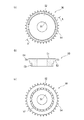
図5は、このような焼結部品を加圧成形する従来の粉末成形用金型を示す断面図である。図5に示すように、従来の粉末成形用金型100は、成形孔101aを有するダイ101と、ダイ101の成形孔101aに上方から挿入される円筒状の上パンチ102と、ダイ101の成形孔101aに下方から挿入される円筒状の第1及び第2下パンチ103,104と、コアロッド105とを備えている。粉末成形用金型100は、上パンチ102の下端部と、第1及び第2下パンチ103,104の各上端部とで金属粉末を加圧することにより、粉末成形体200の本体部201、鍔部202及び歯部203を成形する。
FIG. 5 is a cross-sectional view showing a conventional powder molding die for pressure-molding such sintered parts. As shown in FIG. 5, a conventional powder molding die 100 includes a die 101 having a
図6(a)は、図5のC−C矢視拡大断面図であり、加圧成形前の状態を示している。図6(a)に示すように、ダイ101の成形孔101aの内周には、粉末成形体200の歯部203を成形する内周起伏部101bが全周に亘って形成されている。また、第1下パンチ103の外周には、前記歯部203を成形する外周起伏部103aが全周に亘って形成されている。
第1下パンチ103の外周起伏部103aは、ダイ101の内周起伏部101bに対して、全周に亘って径方向内側にオフセットさせるように形成されている。このため、従来の第1下パンチ103の外周起伏部103aとダイ101の内周起伏部101bとの間には、全周に亘って一定のクリアランスS’が設けられている。これにより、第1下パンチ103は、粉末成形体200の加圧成形時に、ダイ101の成形孔101aに対して上下方向に摺動可能とされている。
FIG. 6A is an enlarged sectional view taken along the line CC in FIG. 5 and shows a state before pressure molding. As shown in FIG. 6A, an inner peripheral undulating
The outer peripheral undulating
従来の粉末成形用金型100により粉末成形体200を加圧成形するとき、図5に示すように、本体部201の外周面により第1下パンチ103の上端部の内周面に径方向外方へ押圧する内圧P’が作用する。このため、第1下パンチ103の上端部の外周起伏部103aは、前記内圧P’によって径方向外側に膨らむように弾性変形する。その際、図6(b)に示すように、第1下パンチ103の外周起伏部103aは、ダイ101の内周起伏部101bにおける歯部203の歯底を成形する部分に線接触A’するように弾性変形する場合がある。このような弾性変形が生じた場合、前記線接触A’部分において応力集中が発生するため、第1下パンチ103の外周がダイ101の成形孔101aに強く押し付けられた状態で上下方向に摺動することで、第1下パンチ103の外周に焼き付きやムシレ等の損傷が発生するという問題があった。
本発明は、前記問題点に鑑みてなされたものであり、粉末成形体の加圧成形時に下パンチの外周が損傷するのを抑制することができる粉末成形用金型を提供することを目的としている。
When the powder compact 200 is pressure-molded by the conventional
The present invention has been made in view of the above problems, and an object of the present invention is to provide a powder molding die that can suppress the outer periphery of the lower punch from being damaged during pressure molding of a powder molded body. Yes.
本発明の粉末成形用金型は、円筒状の本体部の外周に鍔部が形成され、前記鍔部の外周に歯部が形成されてなる粉末成形体を加圧成形する粉末成形用金型であって、前記歯部を成形すべく径方向に起伏する内周起伏部が内周に形成された成形孔を有するダイと、前記成形孔に上方から挿入される上パンチと、前記成形孔に下方から挿入され、前記歯部を成形すべく径方向に起伏するとともに前記内周起伏部に対して径方向内側に所定のクリアランスを設けて配置された外周起伏部が外周に形成された下パンチとを備え、前記外周起伏部における前記歯部の歯底を成形する部分は、前記外周起伏部が前記加圧成形時に弾性変形した状態で、前記内周起伏部における前記歯部の歯底を成形する部分と同一の起伏形状となるように形成されていることを特徴とする。 The powder molding die of the present invention is a powder molding die that press-molds a powder molded body in which a collar is formed on the outer periphery of a cylindrical main body and a tooth is formed on the outer periphery of the collar. A die having a molding hole in which an inner circumferential undulation portion that undulates in the radial direction to mold the tooth portion is formed, an upper punch inserted into the molding hole from above, and the molding hole The outer peripheral undulating portion is formed on the outer periphery, and is inserted from below into the outer peripheral undulating portion, and is undulated in the radial direction so as to form the tooth portion and provided with a predetermined clearance radially inward with respect to the inner peripheral undulating portion. A portion for forming the tooth bottom of the tooth portion in the outer circumferential undulation portion in a state where the outer circumferential undulation portion is elastically deformed during the pressure molding, and the tooth bottom of the tooth portion in the inner circumferential undulation portion It is formed to have the same undulation shape as the part to be molded. The features.
本発明によれば、下パンチの外周起伏部における歯部の歯底を成形する部分は、粉末成形体の加圧成形時に外周起伏部が弾性変形した状態で、ダイの内周起伏部における歯部の歯底を成形する部分と同一の起伏形状となるように形成されているため、粉末成形体の加圧成形時に下パンチの外周起伏部が弾性変形したときに、外周起伏部の前記歯底を成形する部分と、内周起伏部の前記歯底を成形する部分とを面接触させることができる。これにより、外周起伏部の前記歯底を成形する部分と、内周起伏部の前記歯底を成形する部分との接触面圧を分散させることができるため、粉末成形体の加圧成形時に下パンチの外周に焼き付きやムシレ等の損傷が発生するのを抑制することができる。 According to the present invention, the portion forming the tooth bottom of the outer peripheral undulation portion of the lower punch is in a state where the outer peripheral undulation portion is elastically deformed during the pressure molding of the powder molded body, and the teeth in the inner peripheral undulation portion of the die are Since the outer undulations of the lower punch are elastically deformed during the pressure molding of the powder molded body, the teeth of the outer undulations are formed. The part which shape | molds a bottom and the part which shape | molds the said tooth bottom of an internal peripheral undulation part can be surface-contacted. This can disperse the contact surface pressure between the portion of the outer peripheral undulating portion that forms the tooth bottom and the portion of the inner peripheral undulating portion that forms the tooth bottom. It is possible to suppress the occurrence of damage such as seizure or stuffiness on the outer periphery of the punch.
前記外周起伏部の前記同一の起伏形状となる周方向の長さは、前記内周起伏部における前記歯部の歯底から歯先までを成形する周方向の長さの1/3〜1/2の長さに設定されていることが好ましい。
この場合、粉末成形体の加圧成形時に下パンチの外周に焼き付きやムシレ等の損傷が発生するのをさらに効果的に抑制することができる。
The circumferential length of the outer circumferential undulation portion that is the same undulating shape is 1/3 to 1 / of the circumferential length of the inner circumferential undulation portion from the root to the tip of the tooth portion. It is preferable that the length is set to 2.
In this case, it is possible to further effectively suppress the occurrence of damage such as seizure or stuffiness on the outer periphery of the lower punch during the pressure molding of the powder compact.
本発明によれば、粉末成形体の加圧成形時に下パンチの外周が損傷するのを抑制することができる。 ADVANTAGE OF THE INVENTION According to this invention, it can suppress that the outer periphery of a lower punch is damaged at the time of the press molding of a powder compact.
以下、本発明の粉末成形用金型の実施形態を図面に基づいて説明する。
図1は本発明の一実施形態に係る粉末成形用金型の断面図である。この粉末成形用金型1は、成形孔3を有するダイ2と、上パンチ4と、第1下パンチ(下パンチ)5と、第2下パンチ6と、コアロッド7とを備えており、例えば焼結部品であるスプロケットの粉末成形体50を加圧成形するのに用いられる。
Hereinafter, embodiments of a powder molding die of the present invention will be described with reference to the drawings.
FIG. 1 is a sectional view of a powder molding die according to an embodiment of the present invention. The powder molding die 1 includes a
図2は、粉末成形体50を示しており、(a)は平面図、(b)は(a)のA−A矢視断面図、(c)は底面図である。
図2(a)〜(c)において、粉末成形体50は、円筒状の本体部51と、この本体部51の外周に形成された円板状の鍔部52とを備えている。本体部51の外周の下端部には、その全周に亘って小径歯部53が形成されている。鍔部52の外周には、その全周に亘って大径歯部(歯部)54が形成されている。
2A and 2B show the powder compact 50, where FIG. 2A is a plan view, FIG. 2B is a cross-sectional view taken along the line AA in FIG. 2A, and FIG.
2A to 2C, the powder molded
図1において、粉末成形用金型1は、ダイ2の成形孔3に上方から挿入した上パンチ4の下端部と、ダイ2の成形孔3に下方から挿入した第1及び第2下パンチ5,6の各上端部と、コアロッド7の外周面とによって、これらの間に充填された金属粉末を上下方向から加圧することで粉末成形体50を成形する。以下、粉末成形用金型1の構成部材について詳しく説明する。
In FIG. 1, a powder molding die 1 includes a lower end portion of an upper punch 4 inserted from above into a
ダイ2の成形孔3の内周には、その全周に亘って、鍔部52の大径歯部54を成形すべく径方向に起伏する内周起伏部3aが形成されている。
上パンチ4は、円筒状の部材からなり、その下面により粉末成形体50の本体部51の上面及び鍔部52の上面を成形する。また、上パンチ4の外周には、大径歯部54を成形する外周起伏部4aが形成されている。
On the inner periphery of the
The upper punch 4 is made of a cylindrical member, and the upper surface of the
第1下パンチ5は、円筒状の部材からなり、その上端部により粉末成形体50の本体部51の外周面及び鍔部52の下面を成形する。第1下パンチ5の内周には、その全周に亘って、本体部51の小径歯部53を成形すべく径方向に起伏する内周起伏部5aが形成されている。また、第1下パンチ5の外周には、その全周に亘って、鍔部52の大径歯部54を成形すべく径方向に起伏する外周起伏部5bが形成されている。
The 1st
第2下パンチ6は、円筒状の部材からなり、その上面により粉末成形体50の本体部51の下面及び鍔部52の下面を成形する。第2下パンチ6の外周には、その全周に亘って、本体部51の小径歯部53を成形すべく径方向に起伏する外周起伏部6aが形成されている。
The second
図3は、図1のB−B矢視拡大断面図であり、(a)は粉末成形体50を加圧成形する前の状態を示し、(b)は粉末成形体50を加圧成形したときの状態を示している。
図3(a)に示す加圧成形前の状態において、第1下パンチ5の外周起伏部5bは、ダイ2の内周起伏部3aに対して径方向内側に所定のクリアランスS0を設けて配置されている。これにより、第1下パンチ5は、ダイ2の成形孔3に対して上下方向に摺動するようになっている。なお、前記クリアランスS0は、図7に示す従来の一定のクリアランスS’とは異なり、大径歯部54の歯底を成形する部分と、歯先を成形する部分とで異なる大きさとなるように形成されている。
3 is an enlarged cross-sectional view taken along the line B-B in FIG. 1, (a) shows a state before the pressure molding of the powder molded
3A, the outer peripheral undulating
この状態から、粉末成形体50を加圧成形すると、図1に示すように、粉末成形体50の本体部51の外周面により第1下パンチ5の上端部の内周面には、径方向外方へ押圧する内圧Pが作用する。このため、図3(b)に示すように、第1下パンチ5の上端部の外周起伏部5bは、前記内圧Pによって径方向外側(図中の上側)に膨らむように弾性変形する。外周起伏部5bの起伏形状は、この弾性変形した状態を基準に設定されている。以下、その設定方法について説明する。
When the
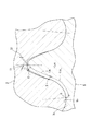
図4は、外周起伏部5bの弾性変形時の起伏形状を示す断面図である。
図4に示すように、外周起伏部5bにおける大径歯部54の歯底を成形する部分のうち、前記歯底の最深点Aから隣接する歯先側に向かって所定長さ離れた中間点Bまでの起伏形状は、ダイ2の内周起伏部3aにおける大径歯部54の歯底を成形する部分と同一の起伏形状となるように形成されている。
この同一の起伏形状となる部分の周方向の長さLABは、内周起伏部3aにおける大径歯部54の歯底から歯先までを成形する周方向の長さ(歯底の最深点Aから歯先の角点Cまでの周方向の長さ)LACの1/3〜1/2の長さに設定されている。
FIG. 4 is a cross-sectional view showing the undulation shape during elastic deformation of the outer
As shown in FIG. 4, in the portion forming the root of the large-
The circumferential length L AB of the portion having the same undulating shape is the circumferential length (the deepest point of the tooth bottom) that forms from the root to the tip of the large-
外周起伏部5bの中間点Bから角点Cまでを成形する周方向の長さLBCにおける起伏形状は、ダイ2の内周起伏部3aにおける中間点Bから角点Cまでの起伏形状に対して、歯先に向かうに従ってクリアランスS1が徐々に大きくなるように形成されている。このクリアランスS1は、例えば0.01〜0.04mmに設定されている。
また、外周起伏部5bにおける前記歯先を成形する部分の起伏形状は、内周起伏部3aの前記歯先を成形する部分の起伏形状に対して、一定のクリアランスS2を設けて形成されている。このクリアランスS2は、例えば0.02〜0.06mmに設定されている。
The undulation shape at the circumferential length L BC forming from the intermediate point B to the corner point C of the outer
Further, the undulation shape of the portion forming the tooth tip in the outer
以上、本実施形態の粉末成形用金型1によれば、第1下パンチ5の外周起伏部5bにおける大径歯部54の歯底を成形する部分は、粉末成形体50の加圧成形時に外周起伏部5bが弾性変形した状態で、ダイ2の内周起伏部3aにおける大径歯部54の歯底を成形する部分と同一の起伏形状となるように形成されているため、粉末成形体50の加圧成形時に第1下パンチ5の外周起伏部5bが弾性変形したときに、外周起伏部5bの前記歯底を成形する部分と、内周起伏部3aの前記歯底を成形する部分とを面接触させることができる。これにより、外周起伏部5bの前記歯底を成形する部分と、内周起伏部3aの前記歯底を成形する部分との接触面圧を分散させることができるため、粉末成形体50の加圧成形時に第1下パンチ5の外周に焼き付きやムシレ等の損傷が発生するのを抑制することができる。
As described above, according to the powder molding die 1 of the present embodiment, the portion for molding the bottom of the large-
今回開示された実施形態はすべての点で例示であって制限的なものでないと考えられるべきである。本発明の範囲は、上記した意味ではなく、特許請求の範囲によって示され、特許請求の範囲と均等の意味、及び範囲内でのすべての変更が含まれることが意図される。
例えば、本実施形態における粉末成形用金型1は、焼結部品であるスプロケットの粉末成形体50を加圧成形する場合について説明したが、前記本体部51、鍔部52及び歯部54を有するものであれば、他の焼結部品の粉末成形体に適用することができる。
また、本実施形態における粉末成形用金型1は、2個の下パンチ(第1下パンチ5及び第2下パンチ6)を備えているが、少なくともダイ2の内周起伏部3aに沿って摺動する外周起伏部5bを有する下パンチを備えていれば、3個以上の下パンチで構成されていてもよい。
It should be thought that embodiment disclosed this time is an illustration and restrictive at no points. The scope of the present invention is defined by the terms of the claims, rather than the meanings described above, and is intended to include any modifications within the scope and meaning equivalent to the terms of the claims.
For example, the powder molding die 1 in the present embodiment has been described with respect to the case where the powder molded
In addition, the powder molding die 1 in this embodiment includes two lower punches (first
1 粉末成形用金型
2 ダイ
3a 内周起伏部
3 成形孔
4 上パンチ
5 第1下パンチ(下パンチ)
5b 外周起伏部
50 粉末成形体
51 本体部
52 鍔部
54 大径歯部(歯部)
DESCRIPTION OF
5b
Claims (2)
前記歯部を成形すべく径方向に起伏する内周起伏部が内周に形成された成形孔を有するダイと、
前記成形孔に上方から挿入される上パンチと、
前記成形孔に下方から挿入され、前記歯部を成形すべく径方向に起伏するとともに前記内周起伏部に対して径方向内側に所定のクリアランスを設けて配置された外周起伏部が外周に形成された下パンチとを備え、
前記外周起伏部における前記歯部の歯底を成形する部分は、前記外周起伏部が前記加圧成形時に弾性変形した状態で、前記内周起伏部における前記歯部の歯底を成形する部分と同一の起伏形状となるように形成されていることを特徴とする粉末成形用金型。 A powder molding die for pressure-molding a powder molded body in which a collar is formed on the outer periphery of a cylindrical main body, and a tooth is formed on the outer periphery of the collar,
A die having a forming hole in which an inner peripheral undulation portion that undulates in the radial direction to form the tooth portion is formed on the inner periphery;
An upper punch inserted into the molding hole from above;
An outer peripheral undulation is formed on the outer periphery, which is inserted into the molding hole from below and undulates in the radial direction to form the tooth portion, and is provided with a predetermined clearance radially inward with respect to the inner peripheral undulation. With a lower punch,
The portion for forming the root of the tooth portion in the outer peripheral undulation portion is a portion for forming the tooth bottom of the tooth portion in the inner peripheral undulation portion in a state where the outer peripheral undulation portion is elastically deformed during the pressure molding. A powder molding die, which is formed to have the same undulating shape.
Priority Applications (1)
| Application Number | Priority Date | Filing Date | Title |
|---|---|---|---|
| JP2013011732A JP2014140877A (en) | 2013-01-25 | 2013-01-25 | Powder molding die |
Applications Claiming Priority (1)
| Application Number | Priority Date | Filing Date | Title |
|---|---|---|---|
| JP2013011732A JP2014140877A (en) | 2013-01-25 | 2013-01-25 | Powder molding die |
Publications (1)
| Publication Number | Publication Date |
|---|---|
| JP2014140877A true JP2014140877A (en) | 2014-08-07 |
Family
ID=51422665
Family Applications (1)
| Application Number | Title | Priority Date | Filing Date |
|---|---|---|---|
| JP2013011732A Pending JP2014140877A (en) | 2013-01-25 | 2013-01-25 | Powder molding die |
Country Status (1)
| Country | Link |
|---|---|
| JP (1) | JP2014140877A (en) |
Citations (5)
| Publication number | Priority date | Publication date | Assignee | Title |
|---|---|---|---|---|
| JPH0551604A (en) * | 1991-08-20 | 1993-03-02 | Nissan Motor Co Ltd | Device for press-forming powder compact to be sintered |
| JP2008246569A (en) * | 2007-03-30 | 2008-10-16 | Honda Motor Co Ltd | Method for manufacturing die for forging |
| JP2009072810A (en) * | 2007-09-20 | 2009-04-09 | Sumitomo Denko Shoketsu Gokin Kk | Molding die for flanged green compact |
| WO2010122769A1 (en) * | 2009-04-20 | 2010-10-28 | 新日本製鐵株式会社 | Molding simulation method, molding simulation device, molding simulation program, and recording medium therefor |
| JP2011088252A (en) * | 2009-10-23 | 2011-05-06 | Ricoh Co Ltd | Method for manufacturing punching device, punching device, paper folding device and image forming device |
-
2013
- 2013-01-25 JP JP2013011732A patent/JP2014140877A/en active Pending
Patent Citations (5)
| Publication number | Priority date | Publication date | Assignee | Title |
|---|---|---|---|---|
| JPH0551604A (en) * | 1991-08-20 | 1993-03-02 | Nissan Motor Co Ltd | Device for press-forming powder compact to be sintered |
| JP2008246569A (en) * | 2007-03-30 | 2008-10-16 | Honda Motor Co Ltd | Method for manufacturing die for forging |
| JP2009072810A (en) * | 2007-09-20 | 2009-04-09 | Sumitomo Denko Shoketsu Gokin Kk | Molding die for flanged green compact |
| WO2010122769A1 (en) * | 2009-04-20 | 2010-10-28 | 新日本製鐵株式会社 | Molding simulation method, molding simulation device, molding simulation program, and recording medium therefor |
| JP2011088252A (en) * | 2009-10-23 | 2011-05-06 | Ricoh Co Ltd | Method for manufacturing punching device, punching device, paper folding device and image forming device |
Similar Documents
| Publication | Publication Date | Title |
|---|---|---|
| CN102869893B (en) | Axial cage for cylinder rolling element | |
| JP5626500B1 (en) | Press forming method | |
| KR20130115363A (en) | Method for producing tooth profile component, and device for producing tooth profile component | |
| JP2009039750A (en) | Method for forging short cylindrical part with flange or the like | |
| EP2926921A3 (en) | Method of manufacturing metal plate having hole, metal plate with hole, external gear with peripheral hole, external gear, metal plate for cam, method of manufacturing metal plate, and metal plate | |
| US11460067B2 (en) | Washer and washer manufacturing method | |
| JP2010142869A (en) | Forging method, device for forming forged product, and tripod-shape constant-velocity universal joint | |
| JP2014140877A (en) | Powder molding die | |
| JP6225018B2 (en) | PRESSING DEVICE AND ROLLER MANUFACTURING METHOD USING THE SAME | |
| CN206106410U (en) | Dress ring device of wound gasket | |
| JP5861965B2 (en) | Sizing mold | |
| JP6412482B2 (en) | Sheet metal member manufacturing method | |
| JP3857116B2 (en) | Powder mold and method for producing powder molded product | |
| JP5679360B2 (en) | Mold for powder molding | |
| JP6503612B2 (en) | Method of producing green compact | |
| JP2019177414A (en) | Insert collar, and manufacturing method thereof | |
| JP5418942B2 (en) | Mold for molding, sizing mold and method for manufacturing sintered part using the same | |
| JP6503583B2 (en) | Method of producing green compact | |
| JP6229828B2 (en) | Method for manufacturing sintered parts | |
| JP2009072810A (en) | Molding die for flanged green compact | |
| JP2012055903A (en) | Insert fitting and method for manufacturing the same | |
| JP6279889B2 (en) | Hole formation method | |
| JP5810465B2 (en) | Mold for powder molding | |
| CN109746437A (en) | A kind of irregularly-shaped hole helical gear one-time forming die | |
| JP5026850B2 (en) | Workpiece manufacturing method |
Legal Events
| Date | Code | Title | Description |
|---|---|---|---|
| A131 | Notification of reasons for refusal |
Free format text: JAPANESE INTERMEDIATE CODE: A131 Effective date: 20140701 |
|
| A521 | Written amendment |
Free format text: JAPANESE INTERMEDIATE CODE: A523 Effective date: 20140808 |
|
| A02 | Decision of refusal |
Free format text: JAPANESE INTERMEDIATE CODE: A02 Effective date: 20150113 |