JP2014139497A - Air conditioning system - Google Patents
Air conditioning system Download PDFInfo
- Publication number
- JP2014139497A JP2014139497A JP2013008688A JP2013008688A JP2014139497A JP 2014139497 A JP2014139497 A JP 2014139497A JP 2013008688 A JP2013008688 A JP 2013008688A JP 2013008688 A JP2013008688 A JP 2013008688A JP 2014139497 A JP2014139497 A JP 2014139497A
- Authority
- JP
- Japan
- Prior art keywords
- room
- air
- ventilation
- conditioning system
- pressure
- Prior art date
- Legal status (The legal status is an assumption and is not a legal conclusion. Google has not performed a legal analysis and makes no representation as to the accuracy of the status listed.)
- Granted
Links
- 238000004378 air conditioning Methods 0.000 title claims abstract description 82
- 238000009423 ventilation Methods 0.000 claims abstract description 92
- 238000007664 blowing Methods 0.000 claims abstract description 40
- 238000005192 partition Methods 0.000 claims abstract description 30
- 238000001514 detection method Methods 0.000 claims description 11
- 238000000034 method Methods 0.000 description 14
- 230000000694 effects Effects 0.000 description 8
- 230000000052 comparative effect Effects 0.000 description 7
- 238000010586 diagram Methods 0.000 description 7
- 230000002093 peripheral effect Effects 0.000 description 6
- 238000005265 energy consumption Methods 0.000 description 4
- 238000013022 venting Methods 0.000 description 4
- 239000000463 material Substances 0.000 description 3
- 238000001816 cooling Methods 0.000 description 2
- 238000004519 manufacturing process Methods 0.000 description 2
- 238000005273 aeration Methods 0.000 description 1
- 238000013459 approach Methods 0.000 description 1
- 230000003749 cleanliness Effects 0.000 description 1
- 230000001276 controlling effect Effects 0.000 description 1
- 238000010438 heat treatment Methods 0.000 description 1
- 238000009434 installation Methods 0.000 description 1
- 239000007788 liquid Substances 0.000 description 1
- 238000012986 modification Methods 0.000 description 1
- 230000004048 modification Effects 0.000 description 1
- 238000012545 processing Methods 0.000 description 1
- 230000001105 regulatory effect Effects 0.000 description 1
Images


Abstract
Description
本発明は、空調システムに関する。 The present invention relates to an air conditioning system.
特許文献1のグリルは、空調システムに用いられるものであり、多数個のルーバー壁が平行に設けてあるグリル本体と、グリル本体の通気量を調整する通気調整機構とを含んで構成されている。通気調整機構は、換気通路を開閉する調整弁と、調整弁を開閉操作する調整具とを有している。そして、特許文献1のグリルでは、調整具をルーバー壁に沿ってスライド変位させて調整弁の開閉度合を変化させることで、排気通路の空気通過量(通気量)を調整している。 The grill of Patent Document 1 is used in an air conditioning system, and includes a grill main body in which a large number of louver walls are provided in parallel, and a ventilation adjustment mechanism that adjusts the ventilation amount of the grill main body. . The ventilation adjustment mechanism includes an adjustment valve that opens and closes the ventilation passage and an adjustment tool that opens and closes the adjustment valve. In the grill of Patent Document 1, the amount of air passing through the exhaust passage (aeration amount) is adjusted by sliding the adjustment tool along the louver wall to change the opening / closing degree of the adjustment valve.
しかし、特許文献1では、部屋に送風する送風機を動作させたときのグリルの使用については記載されていなかった。このため、特許文献1の構成では、部屋の一部に外部への通気が可能な通気部があり且つ排気通路の通気量が少ない場合に、通気部から外部へ流れる通気量が増加し、風切音が生じることがあった。 However, Patent Document 1 does not describe use of a grill when operating a blower that blows air into a room. For this reason, in the configuration of Patent Document 1, when there is a ventilation portion capable of venting to the outside in a part of the room and the ventilation amount of the exhaust passage is small, the ventilation amount flowing from the ventilation portion to the outside increases, There was a noise.
本発明は、外側への通気が可能な通気部を有する部屋に送風手段で送風するときの風切音の発生を抑制することができる空調システムを得ることが目的である。 An object of the present invention is to obtain an air conditioning system capable of suppressing the generation of wind noise when air is blown by a blowing means in a room having a ventilation portion that can vent to the outside.
請求項1の発明に係る空調システムは、送風量が異なる複数の動作モードが切替可能とされ、部屋内に送風する送風手段と、前記部屋内の圧力を検出する圧力検出手段と、前記部屋を構成する壁に設けられ、前記動作モードと前記圧力とに基づいて、前記部屋内から該部屋の外側への通気量を変更する通気量変更手段と、を有する。 The air conditioning system according to the invention of claim 1 is capable of switching a plurality of operation modes having different blast volumes, and is configured to blow air into the room, pressure detecting means for detecting the pressure in the room, and the room. Ventilation amount changing means provided on a wall to be configured and changing a ventilation amount from the inside of the room to the outside of the room based on the operation mode and the pressure.
請求項1の発明に係る空調システムでは、自動又は手動により送風手段の動作モードが切り替えられ(選択され)、送風手段が、選択された動作モードの送風量となるように部屋内へ送風する。そして、圧力検出手段が、部屋内の圧力を検出する。なお、送風される部屋には、該部屋の外側への通気が可能な通気部(例えば、引戸と壁との隙間)が形成されている。 In the air conditioning system according to the first aspect of the present invention, the operation mode of the air blowing means is switched (selected) automatically or manually, and the air blowing means blows air into the room so as to be the air flow rate of the selected operation mode. And a pressure detection means detects the pressure in a room. Note that a ventilating portion (for example, a gap between the sliding door and the wall) capable of venting the outside of the room is formed in the blown room.
ここで、例えば、送風手段のモードが送風量の多い動作モードであり、且つ圧力検出手段で設定圧力よりも高圧が検出されているとき、通気量変更手段が、部屋内から部屋の外側への通気量を増加させる。これにより、部屋内の圧力が低下すると共に、通気部の通気量が増加することが抑制されるので、外側への通気が可能な通気部を有する部屋に送風手段で送風するときの風切音の発生を抑制することができる。一方、送風手段のモードが送風量の少ない動作モードであり、あるいは、圧力検出手段で設定圧力以下の圧力が検出されているときは、通気部で風切音が生じ難いので、通気量変更手段が、通気量を維持するか、又は通気量を減少させる。 Here, for example, when the mode of the air blowing means is an operation mode with a large air flow rate and the pressure detecting means detects a pressure higher than the set pressure, the air flow rate changing means moves from the inside of the room to the outside of the room. Increase air flow. As a result, the pressure in the room is reduced and the increase in the ventilation volume of the ventilation part is suppressed, so that the wind noise when blowing air to the room having the ventilation part capable of venting to the outside by the blowing means Can be suppressed. On the other hand, when the mode of the air blowing means is an operation mode with a small air flow rate or when the pressure detecting means detects a pressure equal to or lower than the set pressure, it is difficult for wind noise to be generated in the air venting portion, so the air flow changing means Maintains air flow or reduces air flow.
請求項2の発明に係る空調システムは、前記部屋内の温度を検出する温度検出手段が設けられ、前記送風手段は、前記温度検出手段で検出された温度が設定温度になるように前記複数の動作モードを切り替える。 An air conditioning system according to a second aspect of the present invention is provided with temperature detecting means for detecting the temperature in the room, and the air blowing means is configured such that the temperature detected by the temperature detecting means becomes a set temperature. Switch the operation mode.
請求項2の発明に係る空調システムでは、温度検出手段で検出された温度が設定温度になるように、送風手段が複数の動作モードを切り替える。例えば、温度検出手段で検出された温度が設定温度よりも高い場合は、送風手段による送風量を増加させ、温度検出手段で検出された温度が設定温度以下の場合は、送風手段による送風量を減少させる。 In the air conditioning system according to the second aspect of the present invention, the air blowing means switches the plurality of operation modes so that the temperature detected by the temperature detecting means becomes the set temperature. For example, when the temperature detected by the temperature detecting means is higher than the set temperature, the air flow rate by the air blowing means is increased. When the temperature detected by the temperature detecting means is lower than the set temperature, the air flow rate by the air blowing means is increased. Decrease.
これにより、請求項2の発明に係る空調システムでは、送風量の多い動作モードのままで送風手段が動作することが防止され、送風手段の動作による過剰な(余分な)エネルギー消費が抑制されるので、空調システムの省エネルギー化を実現することができる。 Thus, in the air conditioning system according to the second aspect of the present invention, it is possible to prevent the air blowing means from operating in the operation mode with a large air flow, and to suppress excessive (excessive) energy consumption due to the operation of the air blowing means. Therefore, energy saving of the air conditioning system can be realized.
請求項3の発明に係る空調システムは、前記通気量変更手段は、前記圧力検出手段によって検出された圧力状態が設定された設定圧力以上の高圧状態で、且つ前記複数の動作モードのうち最も送風量が多い動作モードのとき、他の動作モードよりも通気量を増加させる。 In the air conditioning system according to a third aspect of the present invention, the air flow rate changing means is the highest pressure state in which the pressure state detected by the pressure detection means is equal to or higher than a set pressure, and is the most sent among the plurality of operation modes. In the operation mode with a large air volume, the air flow rate is increased as compared with other operation modes.
請求項3の発明に係る空調システムでは、圧力検出手段によって検出された圧力状態が設定された設定圧力以上の高圧状態で、且つ複数の動作モードのうち最も送風量が多い動作モードとなるまでは、通気量変更手段が通気量を増加させる動作を行わない。これにより、請求項3の発明に係る空調システムでは、通気量変更手段の不要な動作による余分なエネルギー消費が抑制されるので、空調システムの省エネルギー化を実現することができる。 In the air conditioning system according to the third aspect of the present invention, the pressure state detected by the pressure detection means is in a high pressure state that is equal to or higher than the set pressure, and until the operation mode with the largest amount of air flow among the plurality of operation modes. The air flow rate changing means does not perform the operation of increasing the air flow rate. Thus, in the air conditioning system according to the third aspect of the present invention, excessive energy consumption due to unnecessary operation of the ventilation amount changing means is suppressed, so that energy saving of the air conditioning system can be realized.
請求項4の発明に係る空調システムは、前記通気量変更手段は、前記部屋内から外側へ通気可能とする貫通孔が形成された通気部材と、前記通気部材に対する配置角度を変更可能に該通気部材に設けられ、該配置角度の変更により前記貫通孔の通気量を変更する通気量変更部材と、を有する。 According to a fourth aspect of the present invention, there is provided an air conditioning system in which the ventilation amount changing means includes a ventilation member formed with a through hole that allows ventilation from the inside of the room to the outside, and the ventilation angle so that the arrangement angle with respect to the ventilation member can be changed. A ventilation amount changing member that is provided in the member and changes the ventilation amount of the through hole by changing the arrangement angle.
請求項4の発明に係る空調システムでは、通気部材に対する通気量変更部材の配置角度が変更されることで、貫通孔の通気量が変更される。ここで、通気量変更部材は、通気部材に設けられているので、通気量変更部材を通気部材とは異なる場所に設ける構成に比べて、通気量変更部材の設置に必要なスペースが小さくなる。これにより、通気量変更手段の大型化を抑制することができる。 In the air conditioning system according to the fourth aspect of the present invention, the ventilation amount of the through hole is changed by changing the arrangement angle of the ventilation amount changing member with respect to the ventilation member. Here, since the ventilation rate changing member is provided in the ventilation member, a space required for installing the ventilation rate changing member is smaller than a configuration in which the ventilation rate changing member is provided in a place different from the ventilation member. Thereby, the enlargement of the ventilation amount changing means can be suppressed.
請求項5の発明に係る空調システムは、前記通気量変更部材は、前記複数の動作モードのうち最も送風量が多い動作モードにおいて、前記貫通孔の通気量が最大となる配置角度で停止する。 In the air conditioning system according to a fifth aspect of the present invention, the air flow rate changing member stops at an arrangement angle at which the air flow rate of the through hole is maximized in the operation mode with the largest air flow rate among the plurality of operation modes.
請求項5の発明に係る空調システムでは、通気量変更部材が、貫通孔の通気量が最大となる配置角度で停止するので、貫通孔を通過する気体(空気)に作用する抵抗(圧力損失)が最も小さくなる。これにより、部屋内の圧力を低下させ易くすることができる。 In the air conditioning system according to the fifth aspect of the invention, since the air flow rate changing member stops at an arrangement angle at which the air flow rate of the through hole is maximized, the resistance (pressure loss) acting on the gas (air) that passes through the through hole. Becomes the smallest. Thereby, the pressure in the room can be easily reduced.
請求項6の発明に係る空調システムは、前記通気量変更部材は、前記圧力検出手段によって検出された圧力状態が設定された設定圧力よりも低い低圧状態のとき、前記貫通孔を覆うように傾斜配置されている。 In the air conditioning system according to the invention of claim 6, the air flow rate changing member is inclined so as to cover the through-hole when the pressure state detected by the pressure detecting means is in a low pressure state lower than a set pressure. Is arranged.
請求項6の発明に係る空調システムでは、部屋内の圧力状態が、設定された設定圧力よりも低い低圧状態のとき、及び送風手段が動作を停止しているとき、通気量変更部材が、貫通孔を覆うように傾斜配置される。これにより、通気量変更部材で光の進行が遮断又は低減されるので、部屋の外側への光漏れを抑制することができる。 In the air conditioning system according to the sixth aspect of the present invention, when the pressure state in the room is a low pressure state lower than the set pressure, and when the air blowing means is stopped, the air flow rate changing member is penetrated. Inclined to cover the hole. Thereby, since advancing of light is interrupted or reduced by the ventilation amount changing member, light leakage to the outside of the room can be suppressed.
請求項7の発明に係る空調システムは、前記送風手段は、第1送風量の第1動作モードと、該第1送風量よりも多い第2送風量の第2動作モードと、該第2送風量よりも多い第3送風量の第3動作モードとを有しており、前記通気量変更手段は、前記圧力検出手段によって検出された圧力状態が設定された設定圧力以上の高圧状態で、且つ前記第3動作モードのとき、前記第1動作モード及び前記第2動作モードよりも通気量を増加させる。 In the air conditioning system according to the seventh aspect of the present invention, the air blowing means includes a first operation mode for the first air flow rate, a second operation mode for the second air flow rate that is greater than the first air flow rate, and the second air supply system. A third operation mode of a third air flow rate that is greater than the air flow rate, and the air flow rate changing means is in a high pressure state that is equal to or higher than a set pressure in which the pressure state detected by the pressure detection means is set, and In the third operation mode, the air flow rate is increased as compared with the first operation mode and the second operation mode.
請求項7の発明に係る空調システムでは、送風手段による部屋内への送風量が3段階で変更可能となるので、送風量を2段階で変更する構成に比べて、送風手段の動作モードを切り替えるときの急激な送風量の変化を抑制することができる。 In the air conditioning system according to the seventh aspect of the invention, since the amount of air blown into the room by the air blowing means can be changed in three stages, the operation mode of the air blowing means is switched compared to a configuration in which the air volume is changed in two stages. It is possible to suppress a sudden change in the amount of air flow.
請求項8の発明に係る空調システムは、前記送風手段は、前記部屋に隣接する他の部屋に設けられ、前記通気量変更手段は、前記部屋と前記他の部屋とを仕切る壁に設けられている。 In the air conditioning system according to an eighth aspect of the present invention, the air blowing means is provided in another room adjacent to the room, and the air flow rate changing means is provided on a wall that partitions the room from the other room. Yes.
請求項8の発明に係る空調システムでは、部屋内の気体(空気)が、通気量変更手段を通って送風手段が設けられている他の部屋へ流れる。これにより、送風手段が部屋内に送風した気体が、送風手段に戻って利用可能となるので、送風手段における気体の利用効率を上げることができる。 In the air conditioning system according to the invention of claim 8, the gas (air) in the room flows through the ventilation amount changing means to another room where the air blowing means is provided. Thereby, since the gas which the ventilation means ventilated in the room returns to the ventilation means and can be used, the utilization efficiency of the gas in a ventilation means can be raised.
請求項1に記載の本発明に係る空調システムによれば、外側への通気が可能な通気部を有する部屋に送風手段で送風するときの風切音の発生を抑制することができるという優れた効果を有する。 According to the air conditioning system of the first aspect of the present invention, it is possible to suppress the generation of wind noise when the air is blown by the air blowing means into the room having the ventilation portion that can vent to the outside. Has an effect.
請求項2に記載の本発明に係る空調システムによれば、空調システムの省エネルギー化を実現することができるという優れた効果を有する。 The air conditioning system according to the second aspect of the present invention has an excellent effect that energy saving of the air conditioning system can be realized.
請求項3に記載の本発明に係る空調システムによれば、空調システムの省エネルギー化を実現することができるという優れた効果を有する。 The air conditioning system according to the third aspect of the present invention has an excellent effect that energy saving of the air conditioning system can be realized.
請求項4に記載の本発明に係る空調システムによれば、通気量変更手段の大型化を抑制することができるという優れた効果を有する。 According to the air conditioning system of the present invention as set forth in claim 4, there is an excellent effect that an increase in the size of the ventilation amount changing means can be suppressed.
請求項5に記載の本発明に係る空調システムによれば、部屋内の圧力を低下させ易くすることができるという優れた効果を有する。 According to the air conditioning system of the present invention described in claim 5, it has an excellent effect that the pressure in the room can be easily reduced.
請求項6に記載の本発明に係る空調システムによれば、部屋の外側への光漏れを抑制することができるという優れた効果を有する。 According to the air conditioning system of the present invention described in claim 6, it has an excellent effect that light leakage to the outside of the room can be suppressed.
請求項7に記載の本発明に係る空調システムによれば、送風手段の動作モードを切り替えるときの急激な送風量の変化を抑制することができるという優れた効果を有する。 According to the air conditioning system of the present invention as set forth in claim 7, it has an excellent effect that it is possible to suppress a sudden change in the air flow rate when the operation mode of the air blowing means is switched.
請求項8に記載の本発明に係る空調システムによれば、送風手段における気体の利用効率を上げることができるという優れた効果を有する。 According to the air conditioning system of the present invention as set forth in claim 8, there is an excellent effect that the utilization efficiency of the gas in the blowing means can be increased.
本実施形態に係る空調システムの一例について説明する。 An example of the air conditioning system according to the present embodiment will be described.
(全体構成)
図1には、本実施形態の一例としての建物10の全体構成が示されている。なお、以後の説明では、建物10の桁方向をX方向(図中の矢印X)、妻方向をY方向(図中の矢印Y)、高さ方向をZ方向(図中の矢印Z)と記載する。
(overall structure)
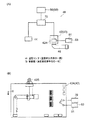
FIG. 1 shows an overall configuration of a
図1に示すように、建物10は、一例として、一階部分12、二階部分14、及び屋根部16を有している。一階部分12及び二階部分14には、Z方向に直立する複数の仕切壁22で仕切られた複数の部屋24、25、26、27、28、29と、一階部分12と二階部分14とを繋ぐ階段ホール30とが形成されている。
As shown in FIG. 1, the
一階部分12では、部屋26、階段ホール30、部屋24、及び部屋25が、X方向にこの順で配置されており、二階部分14では、部屋29、階段ホール30、部屋27、及び部屋28が、X方向にこの順で配置されている。そして、一階部分12には、床17A及び天井19Aが設けられており、二階部分14には、床17B及び天井19Bが設けられている。
In the
階段ホール30には、一階部分12から二階部分14へ移動するための階段32が設けられている。そして、階段32のZ方向下側には、階段ホール30と部屋24とを仕切る仕切壁22(以後、この仕切壁22を仕切壁22Aと記載する)と、床17Aと、階段32とで囲まれた他の部屋の一例としての階段下空間34が形成されている。なお、仕切壁22Aは、壁の一例である。
The
各仕切壁22には、各部屋を連通する出入口と、この出入口を開閉する扉とが設けられているが、図示を省略している。また、各仕切壁22には、通気可能な大きさで隣接する部屋どうしを連通させる通気部36が設けられている。なお、通気部36は、仕切壁22に設けられた扉の下端と床17A、17Bとの間に形成されたアンダーカットに限らず、後述するように、仕切壁22に設けられた扉(引戸35)と仕切壁22との隙間も含む構成である。
Each
建物10には、一階部分12及び二階部分14の空調を行う空調システム40が構築されている。空調とは、建物10の空気調和を行うことであり、温度、湿度、空気清浄度などの室内環境の調整を含む概念である。なお、空調システム40には、換気装置が含まれているが、図示及び説明を省略する。
In the
(要部構成)
次に、空調システム40について説明する。
(Main part configuration)
Next, the
(空調システム)
図1に示すように、空調システム40は、部屋24〜29に送風する送風手段の一例としての室内機42、43と、部屋24、25、27に設けられた圧力検出手段の一例としての圧力センサ44と、通気量変更手段の一例としてのリターングリル50とを有する。室外機41は、送風手段の一例に含まれる。また、空調システム40は、室外機41及び室内機42、43の動作モードと、圧力センサ44の出力(検出結果)とに基づいて、リターングリル50の動作を制御する制御部70(図3(A)参照)を有している。
(Air conditioning system)
As shown in FIG. 1, the
(室内機及び室外機)
室外機41は、建物10の外側に室内機42、43に対応して2台配置されている。室内機42は、一階部分12の階段下空間34内に配置され、室内機43は、屋根部16内に配置されている。そして、室外機41と室内機42、室外機41と室内機43は、熱媒体用配管45A、45Bと制御用の電線(図示省略)とを用いて接続されている。なお、熱媒体用配管45A、45Bは、ガス(気体)状態の熱媒体が流通する配管と液体状態の熱媒体が流通する配管とを含んで構成されている。
(Indoor unit and outdoor unit)
Two
ここで、一例として、一階部分12の部屋24及び階段下空間34における空調システム40について説明する。なお、一階部分12の部屋25及び二階部分14の部屋27についても同様の構成である空調システム40が設けられているが、これらについては後述する。
Here, as an example, the
室内機42には、空気の取込口42Cが形成されている。そして、取込口42Cから取り込まれた空気は、室内機42内において、熱媒体用配管45Aを循環する熱媒体との熱交換によって冷却又は加熱され、部屋24へ向けて送風されるようになっている。
The
室内機42には、床17AのZ方向下側に配置されたチャンバー用ダクト46の一端が接続されており、チャンバー用ダクト46の他端には、床下分岐チャンバー47が設けられている。そして、床下分岐チャンバー47には、吹出用ダクト48A、48B、48Cの一端が接続されており、吹出用ダクト48A、48B、48Cの他端には、部屋24、25、26の床17Aに設けられた床吹出チャンバー49A、49B、49Cが接続されている。さらに、床吹出チャンバー49A、49B、49Cには、部屋24、25、26内への空気の吹出口となる吹出口グリル(図示省略)が設けられている。
One end of a
図3(B)に示すように、室内機42には、室内機42の動作を制御する制御基板42Aが設けられている。制御基板42Aには、送風を行うためのファン(図示省略)を回転駆動するモータ42Bが電気的に接続されている。また、制御基板42Aには、居住者が室内機42を操作するためのコントローラ51(内蔵された温度センサ53含む)、及び制御部70が、電気的に接続されている。これにより、制御基板42Aには、コントローラ51で設定された温度情報、室内機42の動作のON、OFF情報、部屋24(図1参照)内の温度情報が入力されるようになっている。
As shown in FIG. 3B, the
さらに、制御基板42Aでは、室内機42の動作モードの一例である停止、低送風量(第1送風量)のLoモード、標準送風量(第2送風量)のMeモード、及び高送風量(第3送風量)のHiモードを選択(切り替え)可能となっている。そして、室内機42は、一例として、Loモードで第1送風量が800[m3/h]程度の動作、Meモードで第2送風量が1000[m3/h]程度の動作、Hiモードで第3送風量が1200[m3/h]程度の動作を行うようになっている。
Furthermore, in the
ここで、制御基板42Aでは、コントローラ51(温度センサ53(図3(A)参照)内蔵)で設定された設定温度Tsと、コントローラ51に内蔵された温度センサ53で検出された温度Tとが比較される。そして、制御基板42Aでは、温度Tが設定温度Tsに近づくように、Lo、Me、Hiモードのいずれかが選択され、モータ42Bの駆動が制御される(動作モードが切り替えられる)。また、室内機42では、暖房動作が選択されれば温風を生成し、冷房動作が選択されれば冷風を生成する。なお、室内機42の動作モード情報は、制御部70に送られるようになっている。
Here, in the
本実施形態では、Loモードが第1動作モードの一例、Meモードが第2動作モードの一例、Hiモードが第3動作モードの一例となっている。 In the present embodiment, the Lo mode is an example of the first operation mode, the Me mode is an example of the second operation mode, and the Hi mode is an example of the third operation mode.
(圧力センサ)
図3(A)に示す圧力センサ44は、一例として、風圧スイッチを含んで構成されている。風圧スイッチは、受圧部が微小な空気圧の変化を検出し、スイッチを作動させて外部電気回路をON、OFF制御するものである。例えば、風圧スイッチとしては、アズビル株式会社製のC4065、C6065等の風圧スイッチを用いることができる。また、圧力センサ44は、部屋24内の天井19A(図1参照)に取付けられており、制御部70に電気的に接続されている。
(Pressure sensor)
As an example, the
本実施形態では、一例として、圧力センサ44が、予め設定された設定圧力である大気圧(1.01325×10⁵[Pa])よりも高い圧力(高圧状態)を検出したとき、OFFからONに切り替わるようになっている。そして、圧力センサ44のON、OFF情報は、制御部70へ送られる。
In the present embodiment, as an example, when the
(温度センサ)
図1に示すように、温度検出手段の一例としての温度センサ53は、コントローラ51に内蔵されており、部屋24の温度を検出する構成となっている。また、図3(A)、(B)に示すように、コントローラ51に内蔵された温度センサ53は、制御基板42Aに電気的に接続されており、コントローラ51に内蔵された温度センサ53の温度情報が、制御基板42Aに送られるようになっている。
(Temperature sensor)
As shown in FIG. 1, a
(仕切壁)
図2(A)に示すように、仕切壁22Aには、Z方向に長い矩形状でX方向に貫通した出入口23が形成されている。また、仕切壁22Aにおける階段下空間34(図1参照)側には、Y方向にスライド可能とされ、出入口23を開放状態又は閉塞状態とする引戸35が設けられている。
(Partition wall)
As shown in FIG. 2A, the
図2(B)には、引戸35が出入口23を閉塞している状態で、引戸35の周辺部をZ方向上側から見た状態が示されている。この状態では、引戸35をX方向に見て、引戸35のY方向端部と、出入口23の周縁部とが重なっている。なお、図2(B)では、X方向の配置関係を明確にするために、引戸35とリターングリル50とを同一平面に配置して示している。
FIG. 2B shows a state in which the peripheral portion of the sliding
ここで、引戸35のY方向端部で且つ部屋24側の側面35Aと、出入口23の周縁部(仕切壁22A)で且つ階段下空間34側の側面23Aとの間には、通気が可能な隙間である通気部36(破線Dで囲まれた範囲)が形成されている。そして、図2(A)に示すように、仕切壁22Aにおける出入口23の上端と天井19Aとの間には、リターングリル50が設けられている。
Here, ventilation is possible between the
(リターングリル)
図4(A)に示すように、リターングリル50は、通気部材の一例としてのグリル本体52と、グリル本体52に設けられ該グリル本体52に対する配置角度θを変更可能とされた通気量変更部材の一例としての複数のフラップ54、55とを有している。さらに、リターングリル50は、複数のフラップ54、55の後述する軸部54A、55Aを回転駆動する駆動部58を有している。
(Return grill)
As shown in FIG. 4A, the
グリル本体52は、一例として、貫通孔56が形成された角筒形状となっており、貫通孔56の貫通方向がX方向に沿うように仕切壁22Aに取付けられている。即ち、グリル本体52は、Y方向で対向配置された側壁52A及び側壁52Bと、Z方向で対向配置された底壁52C及び上壁52Dとを有している(図2(A)参照)。そして、貫通孔56の大きさは、部屋24内から外側(階段下空間34)へ通気可能な大きさとなっている。これにより、部屋24内と階段下空間34とが、貫通孔56を介して連通して(繋がって)いる。
As an example, the grill
フラップ54は、一例として、Y方向を軸方向とする円柱状の軸部54Aと、軸部54Aの外周面から径方向外側へ延びる矩形の板状部54Bとを有している。軸部54Aは、Y方向両端部が、側壁52A、52Bに設けられた軸受部材(図示省略)を用いて回転可能に支持されている。板状部54Bは、リターングリル50の非使用時の初期位置として、軸部54Aの中心を通る水平面Hに対して先端部(軸部54A側とは反対側の端部)がZ方向下側に配置されるように、配置角度θで傾斜配置されている。そして、配置角度θは、一例として、水平面Hから時計回り方向に45[°]となっている。
As an example, the
また、フラップ54は、一例として、グリル本体52内にZ方向に間隔をあけて4つ設けられており、各フラップ54の配置角度はθで揃えられている。さらに、軸部54Aの径方向における板状部54Bの長さは、初期位置において、上側のフラップ54の板状部54Bの先端部が、下側のフラップ54の軸部54Aよりも下側に配置される長さとなっている。即ち、各フラップ54は、初期位置において、X方向に見て互いに重なっており、貫通孔56を覆っている。なお、各フラップ54は、同じ配置角度θで傾斜しているため、Z方向に間隔があいている。これにより、各フラップ54間での通気(矢印Aで示す)が可能となっている。
Further, as an example, four
軸部54Aの回転範囲は、図示しないストッパーで規制されている。このため、各フラップ54は、一例として、水平面Hに対する配置角度θが、時計回り方向に0[°]≦θ≦45[°]の範囲で変更可能となっている。なお、配置角度θ=0[°]は、板状部54Bが水平面Hに沿って配置されていることを意味しており、貫通孔56が全開状態(最も通気量が多くなる開放状態であり、通気を矢印Bで示す)であることを意味している(図4(B)参照)。
The rotation range of the
一方、フラップ55は、一例として、Y方向を軸方向とする円柱状の軸部55Aと、軸部55Aの外周面から径方向外側へ延びる矩形の板状部55Bとを有している。軸部55Aは、Y方向両端部が、側壁52A、52Bに設けられた軸受部材(図示省略)を用いて回転可能に支持されている。板状部55Bは、リターングリル50の非使用時の初期位置として、軸部55Aの中心を通る水平面Hに対して先端部(軸部55A側とは反対側の端部)がZ方向下側に配置されるように、配置角度θで傾斜配置されている。そして、配置角度θは、一例として、水平面Hから反時計回り方向に45[°]となっている。
On the other hand, the
また、フラップ55は、一例として、グリル本体52内にZ方向に間隔をあけて4つ設けられており、各フラップ55の配置角度はθで揃えられている。さらに、軸部55Aの径方向における板状部55Bの長さは、初期位置において、上側のフラップ55の板状部55Bの先端部が、下側のフラップ55の軸部55Aよりも下側に配置される長さとなっている。即ち、各フラップ55は、初期位置において、X方向とは逆方向から見て互いに重なっており、貫通孔56を覆っている。なお、各フラップ55は、同じ配置角度θで傾斜しているため、Z方向に間隔があいている。これにより、各フラップ55間での通気(矢印Aで示す)が可能となっている。
Further, as an example, four
軸部55Aの回転範囲は、図示しないストッパーで規制されている。このため、各フラップ55は、一例として、水平面Hに対する配置角度θが、反時計回り方向に0[°]≦θ≦45[°]の範囲で変更可能となっている。なお、配置角度θ=0[°]は、板状部55Bが水平面Hに沿って配置されていることを意味しており、貫通孔56が全開状態(最も通気量が多くなる開放状態であり、通気を矢印Bで示す)であることを意味している(図4(B)参照)。
The rotation range of the
さらに、4つの軸部54A及び4つの軸部55Aは、グリル本体52のX方向中央でX方向に隣接配置されている。そして、軸部54Aは、モータMを含んで構成される駆動部58によって時計回り方向に回転移動され、軸部55Aは、駆動部58によって反時計回り方向に回転移動されるようになっている。
Further, the four
即ち、4つのフラップ54、55は、グリル本体52のX方向中央でZ方向に沿った対称軸(図示省略)を中心として、X−Z面で逆V字形状となるように対称配置されている。そして、4つのフラップ54、55は、駆動部58によって、互いに逆方向に同じ変化量(角度)で回転移動するように配置角度θが変更される。これにより、リターングリル50では、貫通孔56の通気量(流量)が変更可能となっている。
That is, the four
(制御部)
図3(A)に示す制御部70には、既述のように、室内機42の動作モード情報及び圧力センサ44のON、OFF情報が入力されるようになっている。そして、制御部70は、これらの入力情報に基づいてリターングリル50に指令信号を出力し、駆動部58の動作制御を行う。なお、制御部70は、通気量変更手段の一例に含まれる構成である。
(Control part)
As described above, the operation mode information of the
詳細には、制御部70は、一例として、室内機42のモードがHiモードで且つ圧力センサ44で高圧状態が検出されているとき、リターングリル50の駆動部58を動作させ、フラップ54、55(図4(A)参照)を全開状態(配置角度θ=0[°])とする。また、制御部70は、室内機42のモードがLo、Meモードのとき、あるいは、圧力センサ44で高圧状態が検出されていないとき、駆動部58を動作させ又は動作させずに、フラップ54、55(図4(A)参照)を初期位置(配置角度θ=45[°])とする。
Specifically, as an example, when the mode of the
(比較例)
次に、比較例の空調システム200について説明する。
(Comparative example)
Next, an
比較例として、室内機42の動作モードがHiモードで且つ圧力センサ44がONとなっている場合に、リターングリル50におけるフラップ54、55の配置が初期位置のままとなっている空調システム200があるとする。
As a comparative example, when the operation mode of the
比較例の空調システム200では、図6(B)に示すように、部屋24内の圧力が高圧状態となっても、リターングリル50における通気量が増加しない。このため、比較例の空調システム200では、引戸35及び引戸35の周縁に向けて流れる空気Aの一部が通気部36へ回りこみ、階段下空間34へ向けて流れる。このとき、通気部36を流れる空気Cによって風切音が生じるが、比較例の空調システム200では、この風切音を低減させることができない。
In the
(作用)
次に、本実施形態の作用について説明する。
(Function)
Next, the operation of this embodiment will be described.
制御部70によって実行される空調システム40の制御処理について、図5のフローチャートを参照しつつ説明する。なお、空調システム40の構成については、図1〜図4を参照するものとし、個別の図番の記載は省略する。また、制御部70は、この制御処理を所定の時間周期にて繰り返し行う。
Control processing of the
図5において、ステップS10では、居住者がコントローラ51を操作することにより空調システム40の動作がONとなる。そして、ステップS12へ移行する。
In FIG. 5, in step S <b> 10, the operation of the
続いて、ステップS12では、コントローラ51に内蔵された温度センサ53により部屋24内の温度Tが検出され、ステップS14へ移行する。
Subsequently, in step S12, the temperature T in the
続いて、ステップS14では、制御基板42Aで温度Tと設定温度Tsとが比較され、温度差ΔT=T−Tsが求められる。そして、ステップS16へ移行する。
Subsequently, in step S14, the
続いて、ステップS16では、制御基板42AでΔT=0[℃]であるかどうかが判定される。ΔTがほぼ0[℃]になっていない場合は、室内機42が動作を開始し、ステップS18へ移行する。一方、ΔTがほぼ0[℃]になっている場合は、室内機42を動作させないため、ステップS20へ移行する。なお、ステップS20では、室内機42が動作している場合には、室内機42の動作を停止し、室内機42が動作していない場合は、非動作状態(OFF状態)を維持して、空調システム40の制御を終了する。
Subsequently, in step S16, it is determined whether or not ΔT = 0 [° C.] on the
続いて、ステップS18では、制御基板42Aにおいて、ΔTの大きさに合わせて、Loモード、Meモード、及びHiモードのいずれか1つが選択される。ここでは一例として、ΔTの絶対値が小さい場合から順に、Loモード、Meモード、Hiモードの順で選択される。そして、ステップS22へ移行する。
Subsequently, in step S18, one of the Lo mode, the Me mode, and the Hi mode is selected on the
続いて、ステップS22では、制御部70において、室内機42の動作モードがHiモードであるか否かが判定される。そして、Hiモードの場合は、ステップS24へ移行し、Loモード又はMeモードの場合は、ステップS28へ移行する。
Subsequently, in step S22, the
続いて、ステップS24では、制御部70において、圧力センサ44がONとなっているか否かが判定される。そして、圧力センサ44がONの場合は、ステップS26へ移行し、圧力センサ44がOFFの場合は、ステップS28へ移行する。
Subsequently, in step S24, the
続いて、ステップS26では、制御部70が、リターングリル50の駆動部58を動作させ、フラップ54、55を回転移動させる。ここでは一例として、フラップ54、55が全開状態(貫通孔56の全開状態)となる。そして、ステップS12に戻る。
Subsequently, in step S26, the
一方、ステップS28では、リターングリル50におけるフラップ54、55の配置を初期位置とする。即ち、このステップS28では、通気部36で風切音が生じ難い状態となっているので、リターングリル50が、通気量を初期状態の通気量で維持するか、又は通気量が多い状態から通気量が少ない状態(初期状態)に減少させる。そして、ステップS12に戻る。
On the other hand, in step S28, the arrangement of the
ここで、本実施形態の空調システム40では、ステップS26において、制御部70が、リターングリル50のフラップ54、55を全開状態としている(図4(B)参照)。即ち、リターングリル50における通気量が、Lo、Meモード時のリターングリル50(初期状態)における通気量に比べて増加する。このため、空調システム40では、図6(A)に示すように、通気部36に比べてリターングリル50を通過する空気の比率が高くなると共に、部屋24内の圧力が低下する。即ち、Lo、Meモード時の通気部36の通気量に比べて、通気部36の通気量が増加することが抑制される。これにより、部屋24内に室内機42で送風するときの通気部36における風切音の発生を抑制することができる。
Here, in the
また、空調システム40では、既述のように、コントローラ51に内蔵された温度センサ53で検出された温度Tが設定温度Tsになるように、制御基板42A内でLo、Me、Hiモードを切り替えている。一例として、冷房のとき、制御基板42Aは、温度Tが設定温度Tsよりも高い場合にHiモードに切り替えて室内機42による送風量を増加させる。また、制御基板42Aは、温度Tが設定温度Ts以下の場合にLoモード又はMeモードに切り替え、あるいは動作を停止させて送風量を減少させる。これにより、室内機42が送風量の多いHiモードのままで動作することが防止され、室内機42の動作における過剰な(余分な)エネルギー消費が抑制されるので、空調システム40の省エネルギー化を実現することができる。
Further, in the
さらに、空調システム40では、室内機42の複数の動作モードのうち最も送風量が多いHiモードが、フラップ54、55が動作する(全開状態となる)条件の1つとなっている。このため、フラップ54、55は、室内機42の送風量が最も多い状態となるまでは動作しない(通気量を増加させる動作を行わない)。これにより、空調システム40では、フラップ54、55の不要な動作による余分なエネルギー消費が抑制されるので、空調システム40の省エネルギー化を実現することができる。
Further, in the
加えて、空調システム40では、通気量を変えるフラップ54、55が、グリル本体52に設けられているので、フラップ54、55をグリル本体52とは異なる場所に設ける構成に比べて、フラップ54、55の設置に必要なスペースが小さくなる。これにより、リターングリル50の大型化を抑制することができる。
In addition, in the
また、空調システム40では、フラップ54、55が、貫通孔56の通気量が最大となる配置角度(一例として、配置角度θ=0[°])で停止するので、貫通孔56を通過する気体(空気)に作用する抵抗が最も小さくなる(圧力損失が少ない)。これにより、部屋24内の圧力を低下させ易くすることができる。
Further, in the
さらに、空調システム40では、室内機42がLoモード又はMeモードのとき、及び室内機42が動作を停止しているとき、フラップ54、55が貫通孔56を覆うように傾斜配置されている。詳細には、フラップ54、55が逆V字状に重なって配置されている。これにより、図4(A)に示すように、フラップ54、55によって、X方向又はX方向とは逆方向への光Lの進行が遮断又は低減されるので、空調システム40では、部屋24の外側への光Lの漏れ、及び部屋24内への光Lの進入を抑制することができる。
Further, in the
また、空調システム40では、室内機42による部屋24内への送風量が、3段階で変更可能となるので、送風量を2段階で変更する構成に比べて、室内機42の動作モードを切り替えるときの急激な送風量の変化を抑制することができる。
Further, in the
さらに、空調システム40では、部屋24内の気体(空気)が、リターングリル50を通って、室内機42が設けられている階段下空間34へ流れる。これにより、室内機42が部屋24内に送風した空気が、室内機42に戻って利用可能となるので、室内機42における空気の利用効率を上げることができる。
Further, in the
なお、本発明は上記の実施形態に限定されない。 In addition, this invention is not limited to said embodiment.
図1に示すように、部屋25内に圧力センサ44を設け、さらに、部屋24と部屋25とを仕切る仕切壁22Bにリターングリル50を設けて、制御部70により、仕切壁22Bのリターングリル50を動作制御してもよい。なお、仕切壁22Bのリターングリル50の動作制御は、仕切壁22Aのリターングリル50の動作制御と同様であるため、説明を省略する。
As shown in FIG. 1, a
また、リターングリル50の設置は、一階部分12に限らず、二階部分14であってもよい。例えば、部屋27内に圧力センサ44、温度センサ53(コントローラ51に内蔵)を設け、さらに、階段ホール30と部屋27とを仕切る仕切壁22Cにリターングリル50を設けて、制御部70により、仕切壁22Cのリターングリル50を動作制御してもよい。なお、二階部分14の空調を行う場合は、室内機42に換えて、室内機43を用いる。
The installation of the
室内機43には、一例として、リターンダクト64を介して、階段ホール30の空気を吸い込む吸込チャンバー62が接続されている。また、部屋27、28、29の天井19Bには、吹出口グリル(図示省略)が設けられた吹出チャンバー66A、66B、66Cが設けられており、室内機43と吹出チャンバー66A、66B、66Cとが、吹出用ダクト68A、68B、68Cで接続されている。これにより、室内機43がHiモードで動作し、且つ圧力センサ44で部屋27内の圧力が大気圧よりも高くなったとき、フラップ54、55(図4(A)参照)の配置角度θを小さくして、リターングリル50の通気量を増加させればよい。
As an example, a
なお、部屋24の引戸35が十分開放されている場合は、通気部36での風切音はほとんど生じないので、フラップ54、55を初期位置に配置したままでもよい。また、リターングリル50における通気量の変更は、2段階に限らず、例えば、LoモードのときよりもMeモードのときの通気量を多くし、さらに、MeモードのときよりもHiモードのときの通気量を多くするという、3段階であってもよい。
Note that when the sliding
また、室内機42、43の動作モードは、Lo、Me、Hiに限らず、4段階以上の動作モードであってもよい。そして、リターングリル50の動作条件の一つである室内機42、43の動作モードは、最大の送風量のモードに限らず、例えば、Meモードであってもよい。さらに、送風量の急激な変化が無い場合は、室内機42、43の動作モードがLo、Hiの2段階のみであってもよい。
Moreover, the operation mode of the
送風手段は、ファンにより送風するものに限らず、例えば、空気を加圧して各部屋に送り込むポンプを有するものであってもよい。ただし、送風量を切り替え可能なものを用いる必要がある。 The air blowing means is not limited to the air blown by the fan, and may include, for example, a pump that pressurizes air and sends the air into each room. However, it is necessary to use a switchable air flow rate.
通気量変更手段は、フラップ54、55の配置角度θを変更するものに限らない。例えば、貫通孔が形成された板材の開口率(板材の1つの面の面積に対する貫通孔の開口面積の比率)を、板材に対してスライド移動するシャッタ部材を用いて変更するものであってもよい。また、フラップ54、55の配置角度θは、0[°]と45[°]とを切り替えるものに限らず、他の角度で設定してもよい。さらに、フラップ54、55の数は、4つに限らず、1、2、3、あるいは5以上の数であってもよい。
The ventilation amount changing means is not limited to changing the arrangement angle θ of the
また、通気量変更手段が設けられる「部屋を構成する壁」とは、部屋と部屋とを仕切る仕切壁22に限らず、底壁(床17)や、上壁(天井19)を含む概念である。
The “wall constituting the room” provided with the ventilation amount changing means is not limited to the
フラップ54、55の板状部54B、55Bは、X−Z断面が矩形状のものに限らず、X−Z断面で三角形状、紡錘状、楕円形状等、他の断面形状であってもよい。また、フラップ54のみ、あるいは、フラップ55のみを用いる構成としてもよい。
The plate-
さらに、本実施形態では、一例として、室内機42の動作モードを、コントローラ51に内蔵された温度センサ53からの温度情報に基づいて切り替える自動方式としたが、居住者がコントローラ51で直接、Lo、Me、Hiモードを選択する手動方式としてもよい。
Furthermore, in this embodiment, as an example, the operation mode of the
加えて、本実施形態は、コントローラ51に温度センサ53を内蔵するものに限らず、図7に示すように、建物10(一例として部屋24、27)において、コントローラ51と温度センサ53とを別々に設けてもよい。
In addition, in the present embodiment, the
圧力センサ44における所定の設定圧力は、大気圧(1.01325×10⁵[Pa])に限らず、他の圧力値で設定してもよい。
The predetermined set pressure in the
10 建物
22 仕切壁(壁の一例)
24 部屋
34 階段下空間(他の部屋の一例)
40 空調システム
41 室外機(送風手段の一例)
42 室内機(送風手段の一例)
43 室内機(送風手段の一例)
44 圧力センサ(圧力検出手段の一例)
50 リターングリル(通気量変更手段の一例)
52 グリル本体(通気部材の一例)
53 温度センサ(温度検出手段の一例)
54 フラップ(通気量変更部材の一例)
55 フラップ(通気量変更部材の一例)
56 貫通孔
70 制御部(通気量変更手段の一例)
10
24
40 Air-
42 Indoor unit (example of blower)
43 Indoor unit (example of blower)
44 Pressure sensor (an example of pressure detection means)
50 return grill (an example of air flow change means)
52 Grill body (example of ventilation member)
53 Temperature sensor (example of temperature detection means)
54 Flap (an example of ventilation rate changing member)
55 flaps (example of ventilation rate changing member)
56 through-
Claims (8)
前記部屋内の圧力を検出する圧力検出手段と、
前記部屋を構成する壁に設けられ、前記動作モードと前記圧力とに基づいて、前記部屋内から該部屋の外側への通気量を変更する通気量変更手段と、
を有する空調システム。 A plurality of operation modes having different air blowing amounts can be switched, and air blowing means for blowing air into the room,
Pressure detecting means for detecting the pressure in the room;
Ventilation amount changing means provided on a wall constituting the room, and changing a ventilation amount from the inside of the room to the outside of the room based on the operation mode and the pressure;
Having air conditioning system.
前記送風手段は、前記温度検出手段で検出された温度が設定温度になるように前記複数の動作モードを切り替える請求項1に記載の空調システム。 Temperature detecting means for detecting the temperature in the room is provided;
2. The air conditioning system according to claim 1, wherein the air blowing unit switches the plurality of operation modes so that a temperature detected by the temperature detection unit becomes a set temperature.
前記部屋内から外側へ通気可能とする貫通孔が形成された通気部材と、
前記通気部材に対する配置角度を変更可能に該通気部材に設けられ、該配置角度の変更により前記貫通孔の通気量を変更する通気量変更部材と、
を有する請求項1から請求項3のいずれか1項に記載の空調システム。 The ventilation amount changing means is
A ventilation member formed with a through hole that allows ventilation from the inside of the room to the outside;
A ventilation amount changing member that is provided in the ventilation member so that the arrangement angle with respect to the ventilation member can be changed, and that changes the ventilation amount of the through hole by changing the arrangement angle;
The air conditioning system according to any one of claims 1 to 3, further comprising:
前記通気量変更手段は、前記圧力検出手段によって検出された圧力状態が設定された設定圧力以上の高圧状態で、且つ前記第3動作モードのとき、前記第1動作モード及び前記第2動作モードよりも通気量を増加させる請求項1から請求項6のいずれか1項に記載の空調システム。 The air blowing means includes a first operation mode of a first air flow rate, a second operation mode of a second air flow rate greater than the first air flow rate, and a third air flow rate greater than the second air flow rate. Operation mode,
The air flow rate changing means is a state in which the pressure state detected by the pressure detecting means is a high pressure state that is equal to or higher than a set pressure, and the first operation mode and the second operation mode when in the third operation mode. The air conditioning system according to any one of claims 1 to 6, wherein the air flow is also increased.
前記通気量変更手段は、前記部屋と前記他の部屋とを仕切る壁に設けられている請求項1から請求項7のいずれか1項に記載の空調システム。 The air blowing means is provided in another room adjacent to the room,
The air conditioning system according to any one of claims 1 to 7, wherein the ventilation amount changing means is provided on a wall that partitions the room from the other room.
Priority Applications (1)
| Application Number | Priority Date | Filing Date | Title |
|---|---|---|---|
| JP2013008688A JP6061695B2 (en) | 2013-01-21 | 2013-01-21 | Air conditioning system |
Applications Claiming Priority (1)
| Application Number | Priority Date | Filing Date | Title |
|---|---|---|---|
| JP2013008688A JP6061695B2 (en) | 2013-01-21 | 2013-01-21 | Air conditioning system |
Publications (2)
| Publication Number | Publication Date |
|---|---|
| JP2014139497A true JP2014139497A (en) | 2014-07-31 |
| JP6061695B2 JP6061695B2 (en) | 2017-01-18 |
Family
ID=51416278
Family Applications (1)
| Application Number | Title | Priority Date | Filing Date |
|---|---|---|---|
| JP2013008688A Active JP6061695B2 (en) | 2013-01-21 | 2013-01-21 | Air conditioning system |
Country Status (1)
| Country | Link |
|---|---|
| JP (1) | JP6061695B2 (en) |
Cited By (5)
| Publication number | Priority date | Publication date | Assignee | Title |
|---|---|---|---|---|
| JP2014190666A (en) * | 2013-03-28 | 2014-10-06 | Toyota Home Kk | Building air conditioning system |
| JP2017116231A (en) * | 2015-12-25 | 2017-06-29 | 大阪瓦斯株式会社 | Air conditioning system |
| JP2020085328A (en) * | 2018-11-22 | 2020-06-04 | トヨタホーム株式会社 | Air conditioning system of building |
| CN111486581A (en) * | 2020-03-30 | 2020-08-04 | 珠海格力电器股份有限公司 | Air valve assembly, air conditioning equipment and corresponding control method |
| JP2022003286A (en) * | 2020-06-23 | 2022-01-11 | トヨタホーム株式会社 | building |
Citations (7)
| Publication number | Priority date | Publication date | Assignee | Title |
|---|---|---|---|---|
| JPH11211177A (en) * | 1997-11-18 | 1999-08-06 | Building Res Inst Ministry Of Constr | Ventilation system and ventilation method |
| JP2001065937A (en) * | 1999-08-27 | 2001-03-16 | Mitsubishi Electric Corp | Ventilating device for residence |
| JP2004003837A (en) * | 2003-05-01 | 2004-01-08 | Toshiba Kyaria Kk | Air conditioner |
| JP2004353361A (en) * | 2003-05-30 | 2004-12-16 | Izena:Kk | Rotary guide device used for ventilation, shading/daylighting, or the like |
| EP1840476A2 (en) * | 2006-03-31 | 2007-10-03 | NuAire Limited | Air flow control apparatus |
| JP2010002080A (en) * | 2008-06-18 | 2010-01-07 | Daikin Ind Ltd | Air conditioning system |
| JP2012102999A (en) * | 2012-01-24 | 2012-05-31 | Seigyo Giken:Kk | Room pressure control device |
-
2013
- 2013-01-21 JP JP2013008688A patent/JP6061695B2/en active Active
Patent Citations (7)
| Publication number | Priority date | Publication date | Assignee | Title |
|---|---|---|---|---|
| JPH11211177A (en) * | 1997-11-18 | 1999-08-06 | Building Res Inst Ministry Of Constr | Ventilation system and ventilation method |
| JP2001065937A (en) * | 1999-08-27 | 2001-03-16 | Mitsubishi Electric Corp | Ventilating device for residence |
| JP2004003837A (en) * | 2003-05-01 | 2004-01-08 | Toshiba Kyaria Kk | Air conditioner |
| JP2004353361A (en) * | 2003-05-30 | 2004-12-16 | Izena:Kk | Rotary guide device used for ventilation, shading/daylighting, or the like |
| EP1840476A2 (en) * | 2006-03-31 | 2007-10-03 | NuAire Limited | Air flow control apparatus |
| JP2010002080A (en) * | 2008-06-18 | 2010-01-07 | Daikin Ind Ltd | Air conditioning system |
| JP2012102999A (en) * | 2012-01-24 | 2012-05-31 | Seigyo Giken:Kk | Room pressure control device |
Cited By (7)
| Publication number | Priority date | Publication date | Assignee | Title |
|---|---|---|---|---|
| JP2014190666A (en) * | 2013-03-28 | 2014-10-06 | Toyota Home Kk | Building air conditioning system |
| JP2017116231A (en) * | 2015-12-25 | 2017-06-29 | 大阪瓦斯株式会社 | Air conditioning system |
| JP2020085328A (en) * | 2018-11-22 | 2020-06-04 | トヨタホーム株式会社 | Air conditioning system of building |
| JP7184484B2 (en) | 2018-11-22 | 2022-12-06 | トヨタホーム株式会社 | building air conditioning system |
| CN111486581A (en) * | 2020-03-30 | 2020-08-04 | 珠海格力电器股份有限公司 | Air valve assembly, air conditioning equipment and corresponding control method |
| JP2022003286A (en) * | 2020-06-23 | 2022-01-11 | トヨタホーム株式会社 | building |
| JP7349411B2 (en) | 2020-06-23 | 2023-09-22 | トヨタホーム株式会社 | building |
Also Published As
| Publication number | Publication date |
|---|---|
| JP6061695B2 (en) | 2017-01-18 |
Similar Documents
| Publication | Publication Date | Title |
|---|---|---|
| KR100665999B1 (en) | Duct type air conditioner combined with ventilation | |
| JP6061695B2 (en) | Air conditioning system | |
| JP2021139620A (en) | Indoor unit of air conditioner | |
| JP6832760B2 (en) | Air conditioning system and building | |
| WO2018180607A1 (en) | Air blowing device and indoor air conveying system using same | |
| WO2019230201A1 (en) | Ventilation system, air-conditioning system, and method for installing air-conditioning system | |
| JP2009264607A (en) | Air conditioning system | |
| WO2018056191A1 (en) | Heat exchange-type ventilation device | |
| JP7142969B2 (en) | air conditioning system | |
| JP5784654B2 (en) | Air conditioning system and air conditioning method | |
| JP2015169399A (en) | Ventilator | |
| JP2015206547A (en) | Blast system | |
| JP7170592B2 (en) | ventilation system | |
| JP2010032099A (en) | Ventilation system | |
| JP2011190941A (en) | Air conditioner | |
| KR100696716B1 (en) | Multi system using energy recovery ventilation | |
| JP5489794B2 (en) | Blower | |
| JP2002039606A (en) | Air supply fan unit | |
| JP2016099034A (en) | Air conditioning device, adjustment method of air conditioning device and manufacturing method of air conditioning facility | |
| JPH10288386A (en) | Air-conditioning device | |
| JP2001027428A (en) | Air conditioner | |
| JP2020165606A (en) | Air conditioning system | |
| JP2019174103A (en) | Air conditioning system | |
| JP2006242492A (en) | Air conditioner | |
| JP7366712B2 (en) | Indoor air temperature diffusion system |
Legal Events
| Date | Code | Title | Description |
|---|---|---|---|
| A621 | Written request for application examination |
Free format text: JAPANESE INTERMEDIATE CODE: A621 Effective date: 20160113 |
|
| A977 | Report on retrieval |
Free format text: JAPANESE INTERMEDIATE CODE: A971007 Effective date: 20161125 |
|
| TRDD | Decision of grant or rejection written | ||
| A01 | Written decision to grant a patent or to grant a registration (utility model) |
Free format text: JAPANESE INTERMEDIATE CODE: A01 Effective date: 20161129 |
|
| A61 | First payment of annual fees (during grant procedure) |
Free format text: JAPANESE INTERMEDIATE CODE: A61 Effective date: 20161213 |
|
| R150 | Certificate of patent or registration of utility model |
Ref document number: 6061695 Country of ref document: JP Free format text: JAPANESE INTERMEDIATE CODE: R150 |
|
| R250 | Receipt of annual fees |
Free format text: JAPANESE INTERMEDIATE CODE: R250 |
|
| R250 | Receipt of annual fees |
Free format text: JAPANESE INTERMEDIATE CODE: R250 |
|
| R250 | Receipt of annual fees |
Free format text: JAPANESE INTERMEDIATE CODE: R250 |